validation, in-depth analysis, and modification of the
TRANSCRIPT

Validation, In-Depth Analysis, and Modification of the Micropipette
Aspiration Technique
YONG CHEN, BAOYU LIU, GANG XU, and JIN-YU SHAO
Department of Biomedical Engineering, Washington University in St. Louis, Campus Box 1097, Rm 290E Whitaker Hall,One Brookings Drive, St. Louis, MO 63130-4899, USA
(Received 29 April 2009; accepted 13 July 2009; published online 24 July 2009)
Abstract—The micropipette aspiration technique (MAT) hasbeen successfully applied to many studies in cell adhesionsuch as leukocyte–endothelium interactions. However, thistechnique has never been validated experimentally and it hasbeen only employed to impose constant forces. In this study,we validated the force measurement of the MAT with theoptical trap and analyzed two technical issues of the MAT,force-transducer offset and cell-micropipette gap, with finiteelement simulation. We also modified the MAT so thatincreasing or decreasing forces can be applied. With themodified MAT, we studied tether extraction from endothelialcells by pulling single tethers at increasing velocities andconstant force loading rates. Before the onset of tetherextraction, an apparently linear surface protrusion of a fewhundred nanometers was observed, which is likely related tomembrane receptors pulling on the underlying cytoskeleton.The strength of the modified MAT lies in its capability andconsistency to apply a wide range of force loading rates fromseveral piconewtons per second up to thousands of piconew-tons per second. With this modification, the MAT becomesmore versatile in the study of single molecule and single cellbiophysics.
Keywords—Cell adhesion, Cellular mechanics, Molecular
biomechanics, Optical trap, Finite element analysis, Tether
extraction.
INTRODUCTION
Small forces ranging from tens of femtonewtons tohundreds of nanonewtons are involved in extendingsingle molecules, rupturing single receptor-ligandbonds, and deforming cellular surfaces. Therefore,measuring or applying these forces is of great impor-tance in biophysics and bioengineering. As such, sev-eral techniques have been developed since the lateeighties, including the atomic force microscope,3 the
optical trap (OT),1 the magnetic force apparatus,33 themicroneedle technique,16 the biomembrane force probe(BFP),7 and the micropipette aspiration technique(MAT).25,30 Although these techniques were employedin earlier studies where the importance of the forceloading rate was not recognized, they have made hugeimpacts in various fields of biology and medicine.
Both the BFP and the MAT are based on amicropipette manipulation system. The differencebetween these two techniques is that the BFP is basedon the principles of solid mechanics, whereas the MATis based on the principles of fluid mechanics. The BFPuses a bead affixed on an inflated red cell or liposomeas the force transducer, whereas the MAT uses aspherical bead or cell placed inside a micropipette (aglass tube) as the force transducer. The red cell orliposome in the BFP serves like a spring, whereas theforce in the MAT is applied by creating fluid flow inthe micropipette. One advantage of the MAT is that itcan be easily applied to cell–cell interactions. Althoughthe MAT has been applied to many interesting studies,including the extensional stiffness of single neutrophilmicrovilli, tether extraction from neutrophils andendothelial cells (ECs), bond formation with contactstress, and single receptor anchoring strength, onlyconstant forces were employed because it was techni-cally limited by a constant pressure.11,18,25,28,34 Withthe MAT, the force (F) imposed through a sphericalforce transducer can be calculated from25
F ¼ pR2pDp 1� 4
3�e
� �1�Ut
Uf
� �; ð1Þ
where Dp is the suction pressure, Rp is the radius of themicropipette, Uf is the transducer velocity when it ismoving freely under Dp, Ut is the transducer velocitywhen it is adherent to a cell or surface, and
�e ¼ ðRp � RbÞ�Rp; ð2Þ
where Rb is the radius of the transducer. Equation (1)was obtained by analyzing the motion of an adherent
Address correspondence to Jin-Yu Shao, Department of Bio-
medical Engineering, Washington University in St. Louis, Campus
Box 1097, Rm 290E Whitaker Hall, One Brookings Drive, St. Louis,
MO 63130-4899, USA. Electronic mail: [email protected] Chen and Baoyu Liu contributed equally to this work.
Cellular and Molecular Bioengineering, Vol. 2, No. 3, September 2009 (� 2009) pp. 351–365
DOI: 10.1007/s12195-009-0071-9
1865-5025/09/0900-0351/0 � 2009 Biomedical Engineering Society
351
or freely moving sphere inside a uniform cylindricaltube with low Reynolds number hydrodynamics.Although no calibration of the MAT with anothertechnique is required for its application, the validity ofEq. (1) has never been compared experimentally withanother well-established technique.
One important problem that has been studiedextensively with the MAT is tether extraction fromleukocytes and ECs.6,10–12,19,34 Tethers are smallmembrane tubes that stabilize leukocyte rolling on theendothelium, which is a key step for the ensuing leu-kocyte arrest on the endothelium.20,36 Under a con-stant aspiration pressure, most tethers are extracted ata constant velocity. Since the diameters of tethersextracted from normal leukocytes and ECs are only intens of nanometers, the existence of tethers is oftenperceived by a smaller transducer velocity (Ut) thataccelerates to a larger free motion velocity (Uf) aftertether extraction is terminated. From the study oftether extraction at many different pressures, a linearrelationship between the pulling force (F) and thetether growth velocity (Ut) can be established15
F ¼ F0 þ 2pgeffUt; ð3Þ
where F0 is the threshold force and geff is the effectiveviscosity. For passive human neutrophils, F0 is 45 pNand geff is 1.8 pN s/lm, both of which are affected bycytokine stimulation.25,31 For human umbilical veinendothelial cells (HUVECs), F0 is around 50 pN andgeff is only 0.5 pN s/lm, neither of which is affected byTNF-a or IL-1 stimulation.11 The comparativelysmaller effective viscosity for HUVECs indicates thatECs can contribute much more to the composite tetherlength when simultaneous tethers are extracted fromboth leukocytes and ECs.38
Despite the potential of the MAT in single molecule,single cell, and cell–cell adhesion studies, two concernsin its application have never been addressed. One isthat the spherical force transducer is sometimes offsetfrom the axisymmetric axis of the cylindrical micropi-pette. This may occur in any MAT study and there aremany possible causes. For example, during tetherextraction, tethers may not be exactly pulled out froma point on the cell that is located on the axis of sym-metry. Although a small and gentle contact betweenthe cell and the force transducer prevents the adhesivebond from being too far from the axis of symmetry, asmall deviation can easily occur. Since Eq. (1) wasestablished with an axisymmetric model, how accu-rately the actual force applied on the offset transducercan be calculated with Eq. (1) is still unknown. Theother concern is related to the studies of attached cellsusing the MAT (e.g., tether extraction from attachedECs). In those studies, a nearly flat EC surface was
placed close to the micropipette tip, creating a smallgap between the micropipette tip and the EC. Thepressure drop over this small gap may compromise onecritical assumption made during the derivation of Eq.(1), i.e., the major pressure drop in the whole flow fieldoccurs mainly inside the micropipette. Consequently, itmay greatly affect the force calculation with Eq. (1).
In this paper, we first validated the MAT by the OTand then analyzed the two concerns associated with theMAT application by finite element analysis. We alsomodified the MAT to impose increasing or decreasingforces at a constant force loading rate on single cells ormolecules. With the modification, we extracted tethersfrom HUVECs using beads coated with anti-PECAM-1(platelet-EC adhesion molecule-1 or CD31) as theforce transducer. Our results showed that, under anincreasing force, the transducer moved at a constantacceleration, which indicates a linear relationshipbetween the pulling force and the tether growthvelocity. More importantly, a linear surface protrusionwas observed before tether extraction and it is likelyrelated to CD31 pulling on the underlying cytoskele-ton. With the modified MAT, a large range of forceloading rates from several piconewtons per second upto more than ten thousand piconewtons per second canbe applied. These additional capabilities of the MATwill certainly broaden its applicability in studyingmechanical properties of single cells and molecules.
MATERIALS AND METHODS
Cell Preparation
Neutrophils were isolated from the blood of healthydonors by finger prick. Briefly, a few drops of bloodwere collected into a heparinized capillary glass tube(Fisher Scientific, Hampton, NH) and overlaid on 200-lL mono-poly resolving medium (MP Biomedicals,Irvine, CA). The sample was then centrifuged at 3009gfor 15 min at room temperature. Afterward, 0.1 mL ofneutrophil-containing medium above the red blood cellpellet was collected and washed in 1-mL Hanks bal-anced salt solution (HBSS; Sigma, Saint Louis, MO) at300 9 g for 5 min. After wash, the cells were resus-pended in 0.1-mL 50% autologous plasma-HBSSsolution, a fraction of which was transferred into theexperimental chamber.
HUVECs were purchased from Cambrex Biosci-ences (Walkersville, MD) and cultured in 6-well plateswith EC medium-2 (Cambrex Biosciences). Forexperiments with suspended HUVECs, confluent cellswere detached with 5 mM EDTA (Sigma), washedwith 0.1% bovine serum albumin (BSA), and thenresuspended in CO2-independent medium (Invitrogen
CHEN et al.352

Corporation, Carlsbad, CA) for immediate use. Forexperiments with attached HUVECs, cells were firstcultured on a cell-culture-treated coverslip (NUNC,Naperville, IL), which was mounted on the inner sidewall of the experimental chamber with silicone adhe-sive (Dow Corning Corporation, Midland, MI). Thewhole chamber was then kept in an incubator for 12 hfor the cells to attach and spread. Prior to experiment,the chamber was removed from the incubator, washed,and refilled with CO2-independent medium.
Validation of the MAT with the OT
The OT combined with a micropipette manipulationsystem was described previously.35 Briefly, an infraredlaser (wavelength 1064 nm) was expanded, directedinto the epifluorescence port of an inverted microscope(Zeiss, Germany), and focused into a tiny spot by anobjective with a high numerical aperture. The focalspot can trap particles in the experimental chamberand serve as a mechanical spring. As shown in Fig. 1a,an anti-PSGL-1 (P-selectin glycoprotein ligand-1)-coated polystyrene bead (~4.5 lm in diameter) wastrapped. The trap stiffness, calibrated with Stokes’drag, was ~0.08 pN/nm. Close to the trapped bead wasa micropipette holding a passive human neutrophil asthe force transducer of the MAT. A constant aspira-tion pressure of 2 pN/lm2 was applied in the MAT toextract tethers from the neutrophil. When a tether wasextracted from the neutrophil, the pulling force wasmeasured simultaneously by the OT and the MAT. Allthe experiments were recorded on a DVD for post-analysis.
Finite Element Simulation
To evaluate the accuracy of using Eq. (1) to calcu-late the force when the bead is offset from the axi-symmetric axis or when there is an attached cell closeto the micropipette tip, the force exerted on thetransducer bead should be determined by anotherreliable means first. To this end, finite element analysiswas chosen since no precise solutions were available.The simulations were performed with FIDAP (FluentIncorporated, Lebanon, NH). Two models (Models Iand II) were developed corresponding to the two sce-narios described above.
In Model I, a three-dimensional (3D) model wasdeveloped for examining the effect of the transduceroffset on the force calculation with Eq. (1) in the MAT.A schematic illustrating the geometrical parameters forthis model is shown in Fig. 2a. In the simulation, thebead radius was 3.9 lm, the pipette inner radius was4 lm, and the pipette length was 60 lm. To simulatethe flow field accurately, finer meshes were generated at
the small gap between the bead and the micropipetteinner wall, where more dramatic changes in pressureand velocity were expected. Altogether, ~500,000 ele-ments were generated in this model.
In Model II, a 2D axisymmetric model was devel-oped for examining how accurate the force calculationwith Eq. (1) is when an opposing surface is positionedclose to the micropipette tip. Figure 2b shows thetypical geometry. The pipette inner radius was 4 lm
OT + MAT
MAT (suspended HUVEC)
MAT (attached HUVEC)
(a)
(b)
(c)
FIGURE 1. (a) One video micrograph showing tetherextraction from a human neutrophil using the OT and the MATsimultaneously. An antibody-coated bead and a passivehuman neutrophil were used as the force transducers of theOT and the MAT, respectively. (b, c) Two video micrographsshowing tether extraction from a suspended (b) or attached(c) HUVEC with an antibody-coated bead (the force transducerof the MAT). A voltage stamp of 5 V (shown actually as‘‘+05.08’’) was used to indicate the instant when the stagestarted to move and the suction pressure started to increase.
Validation and Modification of the MAT 353

and its wall thickness was 3 lm, both of which weredetermined experimentally. The bead radius was3.9 lm and the bead center was 8 lm inside from themicropipette tip. The EC surface was approximated byan arc, which was characterized by the maximumthickness (Hc) and the half length (Lc) of the cell. Thepipette length in this model (L) was about 650 lm(note that only part of the pipette is shown in Fig. 2b).Altogether, ~30,000 elements were generated with finermesh grading specified at both the micropipette tip (theright end of the micropipette as shown in Fig. 2b) andin and around the small gap between the bead and themicropipette.
In both models, appropriate pressure boundaryconditionswere imposed to simulate actual experiments.In Model I, the pressures at the pipette inlet and outletwere set to zero and a negative value, respectively. InModel II, a total pressure drop was set between thepipette outlet and the far field boundary.On the surfacesof the cell, bead, pipette, and substrate, no-slip bound-ary condition was imposed. In all the simulations, thedensity and the viscosity of the medium were set to10�9 pN s2/lm4 (equivalent to 10�9 mg/lm3) and10�3 pN s/lm2 (equivalent to 10�3 N s/m2), respec-tively.
Modification of the MAT
The micropipette manipulation system and how itis used in the MAT have been described in detailelsewhere.25,30,31 Briefly, it is composed of an invertedmicroscope, two micropipettes (glass tubes), twomicromanipulators for positioning the micropipettesin the experimental chamber, and two manual manom-eters for controlling the pressures inside the micro-pipettes. With the manual manometers, only constantsuction pressures can be applied without disturbance,resulting in constant forces. In this study, we replacedone of the manual manometers with a motorizedsystem where two vertical translational stages [onemotorized (Physik Instrumente, Auburn, MA. ModelM-501.1PD) and the other manual] are assembledtogether in series. The motorized stage is controlledwith a program written in LabView (NationalInstruments, Austin, TX). With this modification, anincreasing pressure or any pressure pattern can beapplied in the micropipette, thus allowing us toimpose forces with different loading rates andpatterns.
Latex beads coated with goat-anti-mouse antibodies(~8 lm in diameter; Sigma) were washed twice in PBS
Rp
Rb
Dpb
Lp
Axis of symmetry
RbAxis of symmetry
Dbp
Lc
Tp
H
Rp
Lf
L
Hc
Dpc
Pipette wall Cell
(a)
(b)
Bead
FIGURE 2. Geometric dimensions used in the finite element simulations. (a) Model I: Lp = 60 lm, Rp = 4 lm, Rb = 3.9 lm, andDpb = 0–0.08 lm. (b) Model II: H = 30 lm, Lf = 40 lm, Rp = 4 lm, Rb = 3.9 lm, Tp = 3 lm, Dbp = 8 lm, Hc = 4 lm, and Lc = 20 lm.The total pipette length was 650 lm and only part of the pipette is shown. For this particular case, the distance between the cellapex and the pipette tip (Dpc) was 2 lm. The size of the entire simulation area outside the pipette was 30 lm 3 40 lm.
CHEN et al.354

and incubated with mouse anti-human antibodies(anti-CD31; R&D Systems, Minneapolis, MN) for 1 hat 37 �C. The beads were washed twice and resus-pended in PBS prior to use. Glass micropipettes ofdesired diameters (~8 lm in diameter) were preparedwith a vertical pipette puller and a microforge asdescribed elsewhere.25 The narrow opening of themicropipette was filled with 1% BSA and the rest of itwas backfilled with PBS. The bead and micropipettediameters were determined by dividing their opticaldiameters by their corresponding correction factors.31
The gap between the bead and the micropipette was~0.2 lm on average.
Surface Protrusion and Tether Extractionfrom HUVECs
For tether extraction with the MAT, spherical latexbeads coated with mouse antibodies against humanreceptors were used as the force transducer. As shownin Fig. 1b, for suspended HUVECs, the force trans-ducer (i.e., the antibody-coated bead) was aspiratedinto a micropipette that has a slightly larger diameterthan the bead. An EC was held by another micropi-pette with an aspiration pressure that does not deformthe cell much. For surface-attached HUVECs, a singlemicropipette that contains the force transducer wasused (Fig. 1c). In both cases, a positive pressure wasfirst used to drive the transducer bead to contact thecell and then an increasing aspiration pressure startingfrom zero was applied to pull the transducer beadaway from the cell. The increasing pressure wasapplied by moving the motorized stage at a constantspeed. This procedure was repeated for about 50 timesper cell-bead pair at each stage speed. To record theinstant when the stage started to move in each contactevent, an NI-DAQ board (6024E, NI, Austin, TX) wasinstalled on the same computer and incorporated intothe LabView program that controls the motorizedstage as a virtual instrument. When an electrical signalwas sent through the computer to trigger the stagemovement, another 5 V TTL signal was transmittedsimultaneously to a multiplexer through the NI-DAQboard. A voltage stamp of 5 V was then printed on themonitor along with the image signal transmitted fromthe camera until the stage movement stopped (Fig. 1c).The whole experiment was recorded onto a DVD witha Sony DVD recorder. Typically, the adhesion fre-quency (the number of adhesion events divided by thenumber of contacts) was low (<25%, achieved bydecreasing the antibody concentration on the bead),indicating dominant single-bond interaction andsingle-tether extraction between the bead and thecell.22,27,29
Data Analysis
The analysis procedure of the tether-extractionexperiments has been described in detail elsewhere.25,31
Briefly, the DVD recorded during the tether-extractionexperiments was played in a DVD player and the sig-nal was transmitted to a Windows computer through amonochrome frame grabber. Individual adhesionevents were stored in separate movie files. The dis-placement of the force transducer was then trackedwith the single particle tracking technique,9 which hasa tracking resolution of ~5 nm.
In the experiments where the OT and the MAT wereemployed simultaneously, the displacements of boththe bead in the trap and the cell in the micropipettewere tracked with the single particle tracking techniqueand saved in separate ASCII files. The tether growthvelocity (Ut) and the corresponding free motionvelocity of the cell (Uf) were calculated by linearregression from the cell displacement data. Then themagnitude of the force imposed on the cell was cal-culated with Eq. (1) by taking �e to be zero since it isvery small. The force magnitude was also calculated bymultiplying the trap stiffness by the bead deflection.
In the experiments with the modified MAT, only thebead displacement was tracked. The magnitude of theforce was calculated with Eq. (1). However, since anincreasing aspiration pressure was applied in themicropipette, the bead was moving at an increasingvelocity. Based on different behaviors of the beaddisplacement, different methods were employed tocalculate its velocity (see ‘‘Results’’ section for detaileddescription).
RESULTS
Experimental Validation of the MAT with the OT
Tether extraction from human neutrophils has beeninvestigated with theMAT using either a spherical beador a neutrophil as the force transducer.25,31 In thecurrent study, to save the bead for the optical trap, aspherical neutrophil was used as the force transducer oftheMAT. The bead for the optical trap was coated withantibodies against PSGL-1. Overall 14 tethers wereextracted under a constant suction pressure of 2 pN/lm2. Due to the heterogeneity of the cells, the tethergrowth velocity varied from 1.5 to 5 lm/s (Fig. 3a).However, in most cases, the force magnitudes calcu-lated from the MAT agreed well with the valuesobtained with the OT and the average difference wasonly 8.9 ± 6.4 pN (mean ± standard deviation). Lin-ear regression through the forces obtained with thesetwo techniques yielded statistically indistinguishableslopes, intercepts, and elevations. The strong correlation
Validation and Modification of the MAT 355

between the forces simultaneously measured with theOT and the MAT is shown in Fig. 3b. This demon-strates that the force measurement with the MAT isvery accurate. The average tether growth velocity forthe 14 cases shown in Fig. 3a was 3.0 lm/s and thecorresponding pulling force was 57 pN, both of whichare consistent with our previous results obtained frompassive human neutrophils using the MAT.31,34
Finite Element Analysis of the MAT: 1. The Effectof the Transducer Offset on the Force Calculation
To determine whether the force calculation withEq. (1) is accurate enough when the bead is offset fromthe pipette axis in the MAT, we developed a 3D modelwith finite element analysis and compared its resultswith those from the MAT. Five cases with differentoffsets (i.e., different distances between the beadcenter and the micropipette axis of symmetry, Dpb;
see Fig. 2a) were examined. For all the five values ofDpb ranging from 0 to 0.08 lm, the same total pressuredrop of 2.5 pN/lm2 and the bead velocity of 10 lm/swere used in the simulation. The force applied on theoffset bead, FFEM, was then calculated with FIDAP.To ensure that FFEM is reliable and accurate, werefined themesh for eachmodel until the change inFFEM
was <0.1% after successive refinement. In addition,for the case when Dpb = 0, we compared FFEM withthe force calculated from a 2D axisymmetric modeland found the difference was <0.2%.
To calculate the force on the bead with Eq. (1), thebead free motion velocity (Uf) under the same pressuredrop needs to be obtained in advance. By definition,the free motion velocity is the bead velocity when thehydrodynamic force imposed on the bead is zero. Dueto the linear nature of low Reynolds number flow, thehydrodynamic force is linearly dependent on the beadvelocity. Therefore, simulating the bead motion at tworandomly chosen velocities and calculating the forceson the bead at these two velocities allowed us toaccurately identify the bead free motion velocity, atwhich the force on the bead is zero. This way ofdetermining the free motion velocity was verified bysimulating the bead moving at the identified freemotion velocity and calculating the force applied on thebead, which was <0.01 pN for every case examined.
Denote the force on the bead calculated with Eq. (1)as FEq. The difference between FEq and FFEM repre-sents the error of using Eq. (1) to calculate the forcewhen the bead center is offset from the micropipetteaxis. The relative error (Er) is therefore defined as
Er ¼ ðFEq � FFEMÞ�FFEM
�� ��� 100%: ð4Þ
Figure 4 shows the dependence of the relative errorand FFEM on Dpb. At Dpb = 0, the relative error wasonly about 0.6%; even when the bead was offset for0.08 lm (80% of the maximum offset since the gapbetween the pipette and the bead is generally ~0.1 lm),the relative error was still only 0.7%. These resultsshow that the force calculation with Eq. (1) is fairlyaccurate even when the force transducer is a little offthe micropipette axis of symmetry.
Finite Element Analysis of the MAT: 2. The OptimalDistance Between the Micropipette Tip and Its
Opposing Cell Surface
In the MAT experiment with an attached cell, thecell surface is positioned at a certain distance awayfrom the micropipette tip. When this distance, i.e., thegap between the cell surface and the micropipette tip(Dpc), is getting smaller and smaller, the pressure droparound the micropipette tip, Dpo (note that the total
0
20
40
60
80
100
120
0 1 2 3 4 5 6
Ut (µm/s)
F (
pN
)MAT
OT
30
40
50
60
70
80
90
100
30 40 50 60 70 80 90 100
Fo
rce
Mea
sure
d b
y th
e O
T (
pN
)
Force Measured by the MAT (pN)
R = 0.89
(a)
(b)
FIGURE 3. (a) Pulling forces (F) measured simultaneouslywith the MAT and the OT during tether extraction from humanneutrophils. Although the force magnitudes distributedwidely from 40 pN up to 100 pN due to the cell heterogeneity,the close agreement between the MAT and OT is clear. Thestiffness of the OT was ~0.08 pN/nm and the suction pressurein the micropipette was 2 pN/lm2. (b) Correlation between thepulling forces measured simultaneously with the OT and theMAT.
CHEN et al.356

pressure drop Dp = Dpo + Dpi where Dpi is the pres-sure drop inside the micropipette) will become largerand larger. Consequently, when this distance becomesso small that Dpo becomes a significant portion of Dp,the force calculation with Eq. (1) will become inaccu-rate because the derivation of this equation requiresthe drag around the micropipette tip to be small so thatDp � Dpi. On the other hand, this distance cannot betoo large because most of the transducer body needs tostay inside the micropipette for Eq. (1) to work. Toidentify an optimal distance between the cell and themicropipette tip, six different distances from 0.5 to5 lm were examined in Model II. For all these cases,two different bead velocities (7.5 and 10 lm/s, simu-lating two different tether growth velocities) weresimulated under a total pressure drop of 4.24 pN/lm2.The thickness of the attached EC (Hc) was set to 4 lm,a typical value estimated from the actual experiments.The half length of the cell (Lc) was set at 20 lm. Forevery case considered, the bead free motion velocitywas obtained as described in the previous section.
Shown in Fig. 5a is the comparison between thepressure drop inside the micropipette (Dpi) andthe total pressure drop (Dp). At a given bead velocity,the inner pressure drop decreased while the cell waspositioned closer to the micropipette tip. When Dpc
approached 0.5 lm, the inner pressure drop declinedto ~60–70% of the total pressure drop. In other words,the pressure drop outside the micropipette (mainlyacross the gap between the micropipette tip and theopposing cell surface when the micropipette length isnot too long) increased substantially. To prevent thisfrom happening, a minimum distance of 2 lm shouldbe employed between the micropipette tip and theopposing cell surface. This conclusion was furthersupported by the observation that the force applied on
the transducer bead (calculated using Eq. 1) wasobviously decreased when the distance between themicropipette tip and the cell surface was <2 lm(Fig. 5b). When Dpc was larger than or equal to 2 lm,the calculated forces were not dependent on Dpc; whenDpc was 1 lm, the calculated forces at the beadvelocities of 7.5 and 10 lm/s were significantlydecreased by 17 and 44%, respectively. However, it isintriguing to note that Eq. (1) still predicts the forcevery well even at a distance <2 lm. One possiblereason for this nice agreement is that the bead freemotion velocity is also dependent on Dpc (see moreexplanation in ‘‘Discussion’’ section).
Application of the Modified MAT to Surface Protrusionand Tether Extraction from HUVECs
Tether extraction from both suspended andattached HUVECs has been investigated with theMAT and a linear relationship between the pullingforce (F) and the tether growth velocity (Ut) has beenestablished.11 Previous experiments were carried outwith either constant pulling force or constant pulling
0
0.2
0.4
0.6
0.8
1
90
92
94
96
98
100
0 .00 2 .040 0.06 0.08
Er (%) FFEM
Er (
%)
FF
EM (p
N)
Dpb ( m)
FIGURE 4. Effect of Dpb on the relative error (Er) between thetwo forces calculated from either Eq. (1) (FEq) or FIDAP sim-ulation (FFEM). FFEM is also shown. Five different Dpb values inthe range of 0–0.08 lm were examined at the constant totalpressure drop of 2.5 pN/lm2 and the tether growth velocity of10 lm/s.
50
60
70
80
90
100
0 1 2 3 4 5 6
Dpc (µm)
7.5 µm/s10 µm/s
0
20
40
60
80
100
0 1 2 3 4 5 6
Dpc (µm)
F (
pN)
7.5 µm/s (FEM) 10 µm/s (FEM)7.5 µm/s (Eq. 1) 10 µm/s (Eq. 1)
p i/
p(%
)
(a)
(b)
FIGURE 5. Effect of Dpc on the inner pressure drop in theMAT (a) and the force exerted on the transducer, F (b). Underthe constant total pressure drop of 4.24 pN/lm2, six differentdistances (Dpc) were simulated with the bead velocity at either7.5 or 10 lm/s, simulating tether extraction at two differentvelocities.
Validation and Modification of the MAT 357

velocity. The linear relationship was acquired by fittingthe tether data. With the modified MAT, we can easilyextract tethers at an increasing velocity by applying anincreasing aspiration pressure. The receptor we choseas the force handle was CD31, which is constitutivelyexpressed on ECs.
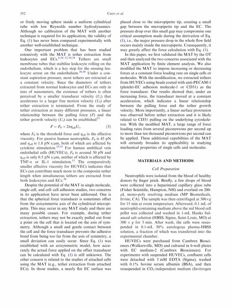
As shown inFig. 6a, if therewas no adhesion betweenthe bead and the cell, the bead moved downstream in aparabolic fashion (D = 0.90t2 � 4.81t + 20.51 whereD is the bead displacement and t is time), i.e., at a
constant acceleration under a linearly increasing pres-sure. This behavior is expecteddue to the linear nature oflow Reynolds number flow in these experiments. Thefree motion velocity at each pressure can be obtained bydifferentiating the parabolic equation. On the otherhand, if adhesion did occur between the bead and thecell, the bead moved downstream as shown in Fig. 6bwhere the stage speed of the manometer was 75 lm/s. Inthis case, twodifferent dynamic regimes canbe identifiedfrom the bead motion.
In the second regime (starting from ~4.7 s), a tetherwas extracted for more than 20 lm before the adhesionwas ruptured at about 9.5 s. After tether extractionwas terminated by adhesion rupture, the bead quicklyaccelerated to its free motion indicating the completeseparation of the bead and the cell. Further analysisshowed that, in this regime, the bead also moved in aparabolic fashion, but with a significantly smalleracceleration, which indicates that tethers were actuallyextracted at a linearly increasing velocity. To charac-terize the relationship between Ut and F, the tethergrowth velocity was first obtained by differentiatingthe displacement–time relationship (D = 0.80t2 �6.12t + 18.30). The total aspiration pressure (Dp) ateach time point was calculated from the stage speedand time, whereas the free motion velocity (Uf) at eachpressure was determined from Fig. 6a. As shown inFig. 7a, it is clear that F has a linear relationship withUt, which could be directly derived theoretically(Eq. B10 in Appendix B). Moreover, it can be shownthat tethers were extracted at a constant force loadingrate (Eqs. B8 and B9 in Appendix B). The corre-sponding force loading rate, effective viscosity, andthreshold force can be obtained by directly fitting thefree or tethered motion of the bead with quadraticequations (Appendix B).
In the first regime shown in Fig. 6b, surface pro-trusion was observed before the onset of tetherextraction. During surface protrusion, the bead trans-lated for ~250 nm in about 2 s. Analyzing the forceapplied on the bead showed that the force increasedlinearly with time (data not shown). The force at theconclusion of surface protrusion was calculated as thecrossover force, which represents the force at whichsurface protrusion transitions to tether extraction. Theforce loading rate during surface protrusion is repre-sented by rfm. As shown in Fig. 6b, the bead movedalmost at a constant velocity during surface protru-sion, which was also true in other cases of our exper-iments. Therefore, we fit the whole initial displacementwith linear regression and used the obtained velocity inall the force calculation during surface protrusion. Thefree motion velocity (Uf) was again calculated fromanalyzing the bead free motion as described above.Further analysis of surface protrusion showed that the
0
10
20
30
40
50
60
0
10
20
30
40
50
60
0 2 4 6 8 10 12
0 2 4 6 8 10 12
Dis
plac
emen
t, D
(m
)D
ispl
acem
ent
(m
)
Time, t (s)
Time (s)
D = 0.90t2 - 4.81t + 20.51R2 = 1.00
Tether broken
Protrusion ended & tether started
Pulling start
(a)
(b)
FIGURE 6. (a) A typical case of the bead free motionobtained with the modified MAT at the stage speed of 75 lm/s.A quadratic equation was used to fit the bead displacementand the resulting correlation coefficient is also shown in thefigure. (b) A typical case of the bead displacement acquired atthe stage speed of 75 lm/s when there was adhesion betweenthe bead and a suspended HUVEC. Both (a) and (b) wereacquired with the same pair of bead and micropipette. Twodifferent regimes, surface protrusion and tether extraction,were identified from the bead displacement. The terminationof the initial surface protrusion could be clearly identified inthe inset figure, which also indicates the onset of tetherextraction.
CHEN et al.358
cell surface was extended linearly (Fig. 7b). For thecase shown in Fig. 7b, the protrusional stiffness (rep-resented by km) was ~320 pN/lm. The termination ofthe initial apparently linear protrusion can be easilyidentified in the inset of Fig. 6b with a crossover forceof ~70 pN (Fig. 7b).
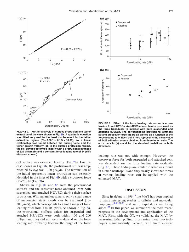
Shown in Figs. 8a and 8b were the protrusionalstiffness and the crossover force obtained from bothsuspended and attached HUVECs during their surfaceprotrusion. With an analog camera, only a small rangeof manometer stage speeds can be examined (10–200 lm/s), which corresponds to a small range of forceloading rates from 5 to 100 pN/s. As shown in Fig. 8a,the protrusional stiffness values for suspended andattached HUVECs were both within 100 and 200pN/lm and they did not seem to depend on the forceloading rate probably because the range of the force
loading rate was not wide enough. However, thecrossover force for both suspended and attached cellswas dependent on the force loading rate evidently(Fig. 8b). These findings are similar to what was foundin human neutrophils and they clearly show that forcesat various loading rates can be applied with theenhanced MAT.
DISCUSSION
Since its debut in 1996,25 the MAT has been appliedto many interesting studies in cellular and molecularbiophysics14,30,34,35 and more capabilities are beingadded.24 In this paper, we summarize the most recentprogress in the development and application of theMAT. First, with the OT, we validated the MAT bymeasuring tether pulling forces using these two tech-niques simultaneously. Second, with finite element
F = 41.56 + 2.77 Ut
40
50
60
70
0 2 4 6 8 10
Ut (µm/s)
F (
pN)
F = 320D
R2 = 0.93
0
10
20
30
40
50
60
70
0.150 .00 5 .10 0.2 0.25
Deformation, D (µm)
F (
pN)
(a)
(b)
Crossover Force
FIGURE 7. Further analysis of surface protrusion and tetherextraction of the case shown in Fig. 6b. A quadratic equationwas fitted very well to the bead displacement in the tetherextraction regime (D = 0.80t2 2 6.12t + 18.30), so a linearrelationship was found between the pulling force and thetether growth velocity (a). In the surface protrusion regime,the cell surface deformed linearly with a protrusional stiffnessof 320 pN/lm (b) and a constant force loading rate of 34 pN/s(data not shown).
0
50
100
150
200
250
300
350
1 10 100
Force loading rate (pN/s)
Force loading rate (pN/s)
Suspended
Attached
0
20
40
60
80
100
1 10 100
Suspended
Attached
Pro
trus
iona
l stif
fnes
s (p
N/µ
m)
(a)
(b)
Cro
ssov
er F
orce
(pN
)
FIGURE 8. Effect of the force loading rate on surface pro-trusion from HUVECs. Anti-CD31-coated beads were used asthe force transducer to interact with both suspended andattached HUVECs. The corresponding protrusional stiffness(a) and crossover force (b) are all plotted as a function of theforce loading rate. Each point here represents the mean valueof 5–22 adhesion events obtained from three to ten cells. Theerror bars in (a) stand for the standard deviations in bothdirections.
Validation and Modification of the MAT 359
simulations, we investigated how the force calculationin the MAT may be affected by the force-transduceroffset from the micropipette axis and the gap betweenthe micropipette tip and the opposing cell surface.Most importantly, we improved the MAT so we canimpose increasing or decreasing forces on single cellsor molecules with controlled force loading rates. Withthis new capability of the MAT, we pulled singlemembrane receptors on ECs with forces loaded in therange of 5–100 pN/s. Two different regimes thatcharacterize distinct cell behaviors were identifiedduring the pulling process. In the first regime, shortsurface protrusion of several hundred nanometers wasobserved and the pulling force had an apparently lin-ear relationship with the cellular deformation(Fig. 7b). In the second regime, membrane tethers wereextracted at linearly increasing velocities under linearlyincreasing forces (Fig. 7a).
The OT functions like a spring with an ultra smallspring constant. For example, the trap stiffness used inthis study was only 0.08 pN/nm. With a tracking res-olution of ~5 nm for the bead deflection in the trap, theOT has a theoretical force resolution of ~0.4 pN. Thishigh force sensitivity makes the OT an ideal candidatefor validating the force measurement with the MAT.However, the transducer bead of the OT cannot beplaced directly in the micropipette because of thepotential optical effect of the pipette on the trap.Therefore, a separate force transducer (i.e., a humanneutrophil) was used in the MAT and the two trans-ducers were connected by a membrane tether whenforces were imposed on them. It should be pointed outthat the maximum force that can be applied with ourOT setup is ~100 pN (other setups may be used toapply forces of a few hundred piconewtons), so weonly applied a small suction pressure of 2 pN/lm2 tokeep the force below 100 pN although much largerforces (a few hundred nanonewtons) can be exertedwith the MAT. One obvious advantage of the MATover the OT is that the force transducer of the MAT isnot heated by laser as in the OT.
The force calculation in the MAT is performed withEq. (1), which was derived by a lubrication analysis withtwo major assumptions: (1) �e is much smaller than one,and (2) the force transducer moves exactly along theaxis of the micropipette. Although the first assumptionis usually valid in the MAT experiments (~2%), thesecond one can easily become invalid. By approximat-ing some terms with higher order series than the onesused by Shao and Hochmuth,25 we derived moreaccurate solutions to this fluid flow problem (AppendixA), but it is still an approximate formula because manyhigher order terms are neglected because of the smallgap between the pipette and force transducer. Althoughthe asymptotic solution obtained by Bungay and
Brenner with perturbation analysis can be applied to thebead offset from the pipette axis,5 their solution is onlyaccurate to the first order, so we chose to carry out finiteelement analysis to evaluate Eq. (1). As expected, our3D model (Model I) demonstrates that neglecting thehigher order terms only causes a small deviation fromthe actual force on the force transducer. More impor-tantly, our 3D model demonstrates that even when thebead is a little offset from the micropipette axis, theforce calculation with Eq. (1) is still very accurate. Inaddition, when a spherical object like a bead movestoward the micropipette wall, it will eventually experi-ence a repulsive force that prevents the bead from get-ting too close to the wall.29 Therefore, it should be oflittle concern if the force transducer is occasionallyoffset from the axisymmetric axis in the MAT experi-ments, as long as the gap between the micropipette andthe force transducer is small.
When the MAT is used to probe attached cells orlarge substrates, the opposing surface outside themicropipette may invalidate another assumption madeduring the derivation of Eq. (1): themajor pressure dropoccurs inside the micropipette. Using our 2D axisym-metric model, we identified an optimal distance betweenthe opposing surface and the micropipette tip in theMAT. In the simulation, we used an arc to approximatethe cell curvature, so the cell is approximated by anaxisymmetric disk with a curved surface. This may notalways be the case for some cell types, such asHUVECs,which are not as elongated in the viewing direction asshown in Fig. 1c. Nevertheless, the higher curvatureregion of the cell (out of the focal plane in Fig. 1c)actually forms a larger gapwith themicropipette tip anddecreases its effect on the inner pressure drop. There-fore, the 2-lm gap criterion should still be valid in thissituation. If the disk-shaped cell was replaced by a largeflat surface, the results were similar (data not shown).
One intriguing outcome from our 2D axisymmetricsimulation (Model II) is that, although the innerpressure drop decreased significantly when the pipette-cell gap fell below 2 lm (Fig. 5a), the force calculationwith Eq. (1) is still very accurate (Fig. 5b). It should benoted that, even when the pipette-cell gap was <2 lm,Eq. (1) should be accurate if we use Dpi and its cor-responding free motion velocity (Ufi) in Eq. (1). On theone hand, the pressure drop used in the force calcu-lation with Eq. (1) (in both the simulation and theactual experiment) was the total pressure drop, Dp,which was larger than the value we should use, Dpi. Onthe other hand, the bead free motion velocity used inthe force calculation with Eq. (1) (again in both thesimulation and the actual experiment), Uf, was smallerthan the value we should use, Ufi. This is because, as inactual experiments, the free motion velocity (Uf) wasobtained while keeping the effect of the pipette-cell
CHEN et al.360

gap. When the gap is small (<2 lm), the larger thebead velocity, the larger Dpo is because of the largerflow rate, so the smaller Dpi is for a constant Dp(Fig. 5a). When the bead is moving freely, it has itsmaximum velocity, so Dpi is at its minimum, making Uf
the minimum value for Ufi. Therefore, we essentiallyused overestimated pressure drop and also overesti-mated free motion velocity in the force calculation withEq. (1) when the bead was moving at 7.5 or 10 lm/s,which is smaller than Uf. The overestimated pressuredrop would result in a larger force and the overesti-mated free motion velocity would result in a smallerforce. These two effects canceled each other, resultingin a force magnitude that agrees well with the actualforce on the transducer. However, we do not expectthis to be true any more when the pipette-cell gapbecomes comparable to the pipette-transducer gap.
Mechanical properties of tether extraction havebeen studied with several different techniques.13,23,25
Besides the linear relationship shown in Eq. (3), apower-law relationship between the pulling force andthe tether growth velocity has also been proposed.4,13
In the present study, we extracted single tethers atincreasing velocities with our modified MAT. Furtheranalysis showed that the tether pulling force is linearlydependent on the tether growth velocity (Appendix B).However, due to the limited lifetime of the adhesion inour experiments, each tether was only extracted in acertain range of velocities, e.g., from 2 to 9 lm/s forthe case shown in Fig. 7b. In a larger velocity range,this relationship should follow the power-law function,as in the data obtained from neutrophil tether extrac-tion over a larger range of tether growth velocities,from 0.4 to 150 lm/s.13 Nevertheless, our study showsthat in a small velocity range, the linear relationshipbetween the pulling force and tether growth velocity isstill reasonable.
The surface protrusion before the onset of tetherextraction from ECs has not been observed in theprevious studies with the MAT. One possible reason isthat a constant aspiration pressure was applied in thoseexperiments, resulting in large initial force loadingrates. Since the force transducer was almost stationaryat the beginning of pulling, the applied force could beso large that surface protrusion was terminatedinstantaneously without being recorded by an analogcamera, which only has a temporal resolution of~0.033 s. Occasionally, we did observe brief pausebefore tether extraction between the cell and the forcetransducer when multiple bonds were formed, whichmay indicate surface protrusion at multiple locations.The underlying mechanism about surface protrusion isstill not completely understood. However, the stiffnessvalues obtained in our study are very close to the resultsobtained from neutrophils studied with the BFP.8 In
the BFP study, by analyzing the crossover force of theinitial surface protrusion from neutrophils, Evans et al.discovered that the force distribution agreed well withthe kinetic model of the rupture of a weak bond, whichis likely the bond between the receptor and the cyto-skeleton. Many receptors that function in leukocyterolling have been found to be linked to the cytoskeletonvia actin binding proteins.2,21,32,37 Truncation of thecytoplasmic tail of most of these receptors, whichabolishes their linkage to the cytoskeleton, couldseverely undermine leukocyte rolling and the ensuingarrest on the endothelium.17,32 Therefore, furtherinvestigation of surface protrusion, especially itsmechanical and kinetic properties, is important tounderstanding and manipulating leukocyte function.
One advantage of using the modified MAT to studythe bond rupture or adhesion strength under a con-stant force loading rate is that the applied force load-ing rate is very consistent once the stage speed is set.For all the data shown in Fig. 8, the maximum stan-dard deviation of the force loading rate was only ~10%of the average value with most of the standard devia-tions <5%. This is because the applied force loadingrate is mainly determined by the stage speed, which isvery consistent with its positional resolution of 8 nm.In the current study, only a small range of forceloading rates of 5–100 pN/s was applied on the forcetransducer. This is because when the pressure drop isincreased rapidly (stage velocity >200 lm/s), thetransducer speed becomes too large to allow good-quality image acquisition by an analog camera.Moreover, even at a moderate stage speed, some shortspeed fluctuations may be missed by an analog camera.In theory, for a stationary 8-lm force transducer in themicropipette, a maximum force loading rate ofapproximately 7,500 pN/s can be obtained. This limitcorresponds to the maximum allowable stage velocityof 15 mm/s. If higher force loading rates are desired,larger force transducers can be used. When the size ofthe force transducer is doubled, the maximum forceloading rate that can be applied will be quadrupled, sothe force loading rate of more than 10,000 pN/s can beeasily imposed with the modified MAT. Therefore, themodification presented in this work endowed the MATwith more potential in its application in cellular andmolecular adhesion studies.
APPENDIX A
Low Reynolds Number Motion of a Concentric CloselyFitted Sphere or Capsule in a Cylindrical Tube
In the MAT, the force transducer (a sphericalobject) moves back and forth in a cylindrical tube. If a
Validation and Modification of the MAT 361

spherical cell is employed as the force transducer andits diameter (Rc) is slightly larger than the pipetteradius (Rp), it can be deformed slightly into a capsuleshape, but an apparent gap between the cell and pip-ette still exists.26 Both scenarios (either a sphere orcapsule) have been analyzed with the lubrication the-ory by Shao and Hochmuth.25,26 However, in thoseanalyses, some terms are not approximated with highaccuracy. As a result, some equations are not veryaccurate, e.g., the equations for calculating the pres-sure drop over the sphere or capsule (Dps or Dpc) andthe force on it (F). In this appendix, we list the equa-tions derived with more accurate approximations.
The pressure drop over the sphere, the pressure dropdue to the fluid flow in the tube (Dpf), and the totalpressure drop in the whole tube (Dp) can be expressed by
Dps ¼lURp
4ffiffiffi2p
p�e1=2
� 32þ 2ffiffiffi2p
p3
�e1=2 þOð�eÞ" #
þ F
pR2p
1þ 4
3�eþ 16
9�e2 þOð�e5=2Þ
� �; ðA1Þ
Dpf ¼8lðLeq � 2RsÞU
R2p
1� 4
3�eþ 16
9�e2 þOð�e5=2Þ
� �
þ 8ðLeq � 2RsÞFpR3
p
2ffiffiffi2p
9p�e5=2 þOð�e7=2Þ
" #; ðA2Þ
Dp¼ lURp
"4ffiffiffi2p
p�e1=2
�32þ2ffiffiffi2p
p3
�e1=2 !
þ8ðLeq�2RsÞRp
1�43�eþ16
9�e2
� �#
þ F
pR2p
1þ43�eþ16
9�e2
� �þ8ðLeq�DsÞ
Rp
2ffiffiffi2p
9p�e5=2
!" #;
ðA3Þ
where l, Rp, Rs, and U are the viscosity, the tuberadius, the sphere radius, and the sphere velocity,respectively; �e ¼ ðRp � RsÞ=Rp: For a stationarysphere (U = 0),
pR2pDps¼�
9ffiffiffi2p
plQ
4Rp�e5=21þ1
6�eþ 59
360�e2þOð�e5=2Þ
� �; ðA4Þ
F ¼ �9ffiffiffi2p
plQ
4Rp�e5=21� 7
6�e� 7
120�e2 þOð�e5=2Þ
� �; ðA5Þ
where Q is the volumetric flow rate. From Eqs. (A4)and (A5), we can get
F
pR2pDps
¼ 1� 4
3�eþ 74
15�e5=2 þOð�e3Þ: ðA6Þ
For a capsule with its cylindrical length of 2ls, thepressure drop over the capsule (Dpc), the pressuredrop due to the fluid flow in the tube, and the totalpressure drop in the whole tube can be expressed by(when �b, which is defined as ls/Rp, is on the order of 1or larger)
Dpc ¼lURp
"10�b�eþ 17
ffiffiffi2p
p
4�e1=2
!
þ 121�b10� 32� 3p2
32�bþ 243p4
4096�b3
� �#
þ F
pR2p
1þ �eþffiffiffi2p
p
16�b�e3=2 þOð�e2Þ
" #; ðA7Þ
Dpf ¼8lURp
Leq
Rp� 2ð1� �eÞ � 2�b
� �
� 1� �e�ffiffiffi2p
p
16�b�e3=2 þ 1
2þ 3p2
128�b2
� ��e2 þOð�e5=2Þ
" #
þ 8F
pR2p
Leq
Rp� 2ð1� �eÞ � 2�b
� �
� p
12�b�e3 �
ffiffiffi2p
p
64�b2�e7=2 þOð�e4Þ
" #; ðA8Þ
Dp ¼ lURp
"10�b�eþ 17
ffiffiffi2p
p
4�e1=2
!
þ 121�b
�e� 32� 3p2
32�bþ 243p4
4096�b3
!
þ 8Leq
Rp� 2ð1� �eÞ � 2�b
� �1� �e�
ffiffiffi2p
p
16�b�e3=2
!#
þ F
pR2p
"1þ �eþ
ffiffiffi2p
p
16�b�e3=2
!
þ 8Leq
Rp� 2ð1� �eÞ � 2�b
� �p
12�b�e3 �
ffiffiffi2p
p
64�b2�e7=2
!#:
ðA9Þ
If �b is on the order of �e or smaller, assume that �b ¼ a�e(a is a constant which is on the order of 1 or smaller),we have:
Dpc ¼lURp
4ffiffiffi2p
p�e1=2
þ �32þ 34
3a� 2048a3
9p2
� �þOð�e1=2Þ
" #
þ F
pR2p
"1þ 4
3�eþ �8
ffiffiffi2p
a9pþ 1024a3
27p3
!�e3=2
þ 16
9� 640a2
27p2
� ��e2 þOð�e5=2Þ
#; ðA10Þ
CHEN et al.362

Dpf¼8lURp
Leq
Rp�2ð1��eÞ�2�b
� �
� 1�4
3�eþ8
ffiffiffi2p
a9p
�e3=2þ 16
9�128a2
27p2
� ��e2þOð�e5=2Þ
" #
þ 8F
pR2p
Leq
Rp�2ð1��eÞ�2�b
� �
� 2ffiffiffi2p
9p�e5=2� 32a
27p2�e3þOð�e7=2Þ
" #; ðA11Þ
Dp¼ lURp
"4ffiffiffi2p
p�e1=2
�32þ34
3a�2048a3
9p2
!
þ 8Leq
Rp�2ð1��eÞ�2�b
� �1�4
3�eþ8
ffiffiffi2p
a9p
�e3=2 !#
þ F
pR2p
"1þ4
3�e� 8
ffiffiffi2p
a9p�1024a3
27p3
!�e3=2
!
þ8 Leq
Rp�2ð1��eÞ�2�b
� �2ffiffiffi2p
9p�e5=2� 32a
27p2�e3
!#:
ðA12Þ
For a stationary capsule (U = 0), when �b is on theorder of 1 or larger, the pressure drop over the bodyand the force on it are:
pR2pDpc ¼ �
9ffiffiffi2p
plQ
4Rp�e5=21þ 1
6�eþ 59
360�e2 þOð�e5=2Þ
� �
� 12lQRp
�b�e3
1þ �e2þ 7�e2
30þ �e3
10þOð�e4Þ
� �;
ðA13Þ
F ¼ � 9ffiffiffi2p
plQ
4Rp�e5=21� 7
6�e� 7
120�e2 þOð�e5=2Þ
� �
� 12lQRp
�b�e3
1� �e2� �e2
10� �e3
20þOð�e4Þ
� �: ðA14Þ
The relative magnitude of these two equations is:
F
pR2pDpc
¼ 1� �e�ffiffiffi2p
p
16�b�e3=2 þOð�e2Þ: ðA15Þ
If �b is on the order of �e or smaller, the solution will be:
pR2pDpc ¼ �
9ffiffiffi2p
plQ
4Rp�e5=2
"1þ 8
ffiffiffi2p
a3p
�e1=2 þ 1
6�eþ 4
ffiffiffi2p
a3p
�e3=2
þ 59
360�e2 þOð�e5=2Þ
#; ðA16Þ
F ¼ � 9ffiffiffi2p
plQ
4Rp�e5=2
"1þ 8
ffiffiffi2p
a3p
�e1=2 � 7
6�e� 4
ffiffiffi2p
a3p
�e3=2
� 7
120�e2 þOð�e5=2Þ
#: ðA17Þ
The relative magnitude of these two equations is:
F
pR2pDpc
¼ 1� 4
3�eþ 8
ffiffiffi2p
a9p
�e3=2 � 128a2
27p2þ 16384a4
81p4
� ��e2
þOð�e5=2Þ: ðA18Þ
APPENDIX B
Calculation of Threshold Force, Effective Viscosity,and Force Loading Rate During Tether Extraction
With the modified MAT, tethers can be extractedfrom cell membranes under an increasing suction pres-sure. During this process, both the tether growthvelocity and the pulling force are increasing so that arelationship between F andUt can be obtained from onetether event. The equation governing the force magni-tude exerted on the force transducer is still the same:
F ¼ pR2pDp 1� 4
3�e
� �1�Ut
Uf
� �: ðB1Þ
In the case of the modified setup, the total pressuredrop Dp is determined by the speed of the moving stage(Vs) according to
Dp ¼ qgVsðt� t0Þ; ðB2Þ
where t0 is the time when the stage starts to move,which can be determined from the reading of voltagestamp (Figs. 1b and 1c). The substitution of Eq. (B2)into Eq. (B1) gives
F ¼ aðt� t0Þ 1�Ut
Uf
� �; ðB3Þ
where
a ¼ pR2pqgVs 1� 4
3�e
� �: ðB4Þ
At a certain stage speed, the free motion of the forcetransducer is parabolic and can be fitted well with anequation of the form D ¼ a2ðt� t0Þ2 þ b2; where D isthe transducer displacement. Accordingly, we canwrite the free motion velocity as
Uf ¼ 2a2ðt� t0Þ: ðB5Þ
Validation and Modification of the MAT 363

The substitution of Eq. (B5) into Eq. (B3) leads to
F ¼ aðt� t0Þ �a2a2
Ut: ðB6Þ
In an actual experiment, when a tether is extractedfrom an EC, the transducer also moves with a para-bolic trajectory. By fitting the trajectory of the trans-ducer with an equation of the form y ¼ a1t
2 þ b1tþ c1;the tether growth velocity can be calculated by
Ut ¼ 2a1tþ b1: ðB7Þ
The substitution of Eq. (B7) into Eq. (B6) then yields
F ¼ a 1� a1a2
� �t� a
b12a2þ t0
� �: ðB8Þ
Because the stage is moving at a constant speed, Vs
(i.e., a is a constant), the tether is actually extracted ata constant force loading rate, given by
rft ¼ a 1� a1a2
� �: ðB9Þ
Finally, the substitution of Eq. (B7) into Eq. (B8) yields
F ¼ a2a1
1� a1a2
� �Ut � a
b12a1þ t0
� �: ðB10Þ
This expression demonstrates that at a constant forceloading rate, the force required to extract a tether islinearly dependent on the tether growth velocity.Consequently, the threshold force and effective vis-cosity can be calculated by
F0 ¼ �ab12a1þ t0
� �; ðB11Þ
geff ¼a
4pa11� a1
a2
� �: ðB12Þ
ACKNOWLEDGMENT
This work was supported by the National Institutesof Health (R01 HL069947 and R21/R33 RR017014).
REFERENCES
1Ashkin, A. Forces of a single-beam gradient laser trap on adielectric sphere in the ray optics regime. Biophys. J.61:569–582, 1992.2Barreiro,O.,M.Yanez-Mo, J.M.Serrador,M.C.Montoya,M. Vicente-Manzanares, R. Tejedor, H. Furthmayr, andF. Sanchez-Madrid. Dynamic interaction of VCAM-1 andICAM-1 with moesin and ezrin in a novel endothelialdocking structure for adherent leukocytes. J. Cell Biol.157:1233–1245, 2002.
3Binnig, G., C. F. Quate, and C. Gerber. Atomic forcemicroscope. Phys. Rev. Lett. 56:930–933, 1986.4Brochard-Wyart, F., N. Borghi, D. Cuvelier, and P.Nassoy.Hydrodynamic narrowing of tubes extruded from cells.Proc. Natl. Acad. Sci. USA 103:7660–7663, 2006.5Bungay, P. M., and H. Brenner. The motion of a closely-fitting sphere in a fluid-filled tube. Int. J. Multiphase Flow.1:25–56, 1973.6Chen, Y., G. Girdhar, and J. Y. Shao. Single membranetether extraction from adult and neonatal dermal micro-vascular endothelial cells. Am. J. Physiol. Cell Physiol.292:C1272–C1279, 2007.7Evans, E., D. Berk, and A. Leung. Detachment of agglu-tinin-bonded red blood cells: I. Forces to rupture molecu-lar-point attachments. Biophys. J. 59:838–848, 1991.8Evans, E., V. Heinrich, A. Leung, and K. Kinoshita.Nano- to microscale dynamics of P-selectin detachmentfrom leukocyte interfaces. I. Membrane separation fromthe cytoskeleton. Biophys. J. 88:2288–2298, 2005.9Gelles, J., B. J. Schnapp, and M. P. Sheetz. Trackingkinesin-driven movements with nanometer-scale precision.Nature 331:450–453, 1988.
10Girdhar, G., Y. Chen, and J. Y. Shao. Double tetherextraction from human umbilical vein and dermal micro-vascular endothelial cells. Biophys. J. 92:1035–1045, 2007.
11Girdhar, G., and J. Y. Shao. Membrane tether extractionfrom human umbilical vein endothelial cells and its impli-cation in leukocyte rolling. Biophys. J. 87:3561–3568, 2004.
12Girdhar, G., and J. Y. Shao. Simultaneous tether extrac-tion from endothelial cells and leukocytes: observation,mechanics and significance. Biophys. J. 93:4041–4052, 2007.
13Heinrich, V., A. Leung, and E. Evans. Nano- to microscaledynamics of P-selectin detachment from leukocyte inter-faces. II. Tether flow terminated by P-selectin dissociationfrom PSGL-1. Biophys. J. 88:2299–2308, 2005.
14Hochmuth, R. M. Micropipette aspiration of living cells.J. Biomech. 33:15–22, 2000.
15Hochmuth, R. M., J. Y. Shao, J. Dai, and M. P. Sheetz.Deformation and flow of membrane into tethers extractedfrom neuronal growth cones. Biophys. J. 70:358–369, 1996.
16Kamimura, S., and K. Takahashi. Direct measurement ofthe force of microtubule sliding in flagella. Nature 293:566–568, 1981.
17Kansas, G. S., K. Ley, J. M. Munro, and T. F. Tedder.Regulation of leukocyte rolling and adhesion to highendothelial venules through the cytoplasmic domain ofL-selectin. J. Exp. Med. 177:833–838, 1993.
18Levin, J. D., H. P. Ting-Beall, and R. M. Hochmuth.Correlating the kinetics of cytokine-induced E-selectinadhesion and expression on endothelial cells. Biophys. J.80:656–667, 2001.
19Marcus, W. D., and R. M. Hochmuth. Experimentalstudies of membrane tethers formed from human neutro-phils. Ann. Biomed. Eng. 30:1273–1280, 2002.
20Park, E. Y., M. J. Smith, E. S. Stropp, K. R. Snapp, J. A.DiVietro, W. F. Walker, D. W. Schmidtke, S. L. Diamond,and M. B. Lawrence. Comparison of PSGL-1 microbeadand neutrophil rolling: microvillus elongation stabilizesP-selectin bond clusters. Biophys. J. 82:1835–1847, 2002.
21Pavalko, F. M., D. M. Walker, L. Graham, M. Goheen,C. M. Doerschuk, and G. S. Kansas. The cytoplasmicdomain of L-selectin interacts with cytoskeletal proteins viaa-actinin: receptor positioning in microvilli does not requireinteraction with a-actinin. J. Cell Biol. 129:1155–1164,1995.
CHEN et al.364

22Piper, J. W., R. A. Swerlick, and C. Zhu. Determining forcedependence of two-dimensional receptor-ligand bindingaffinity by centrifugation. Biophys. J. 74:492–513, 1998.
23Schmidtke, D. W., and S. L. Diamond. Direct observationof membrane tethers formed during neutrophil attachmentto platelets or P-selectin under physiological flow. J. CellBiol. 149:719–729, 2000.
24Shao, J. Y. Finite element analysis of imposing femto-newton forces with micropipette manipulation. Ann. Bio-med. Eng. 30:546–554, 2002.
25Shao, J. Y., and R. M. Hochmuth. Micropipette suctionfor measuring piconewton forces of adhesion and tetherformation from neutrophil membranes. Biophys. J.71:2892–2901, 1996.
26Shao, J. Y., and R. M. Hochmuth. The resistance to flow ofindividual human neutrophils in glass capillary tubes withdiameters between 4.65 and 7.75 lm. Microcirculation4:61–74, 1997.
27Shao, J. Y., and R. M. Hochmuth. Mechanical anchoringstrength of L-selectin, b2 integrins and CD45 to neutrophilcytoskeleton and membrane. Biophys. J. 77:587–596, 1999.
28Shao, J. Y., H. P. Ting-Beall, and R. M. Hochmuth. Staticand dynamic lengths of neutrophil microvilli. Proc. Natl.Acad. Sci. USA 95:6797–6802, 1998.
29Shao, J. Y., and G. Xu. The adhesion between a micro-villus-bearing cell and a ligand-coated substrate: a MonteCarlo study. Ann. Biomed. Eng. 35:397–407, 2007.
30Shao, J. Y., G. Xu, and P. Guo. Quantifying cell-adhesionstrength with micropipette manipulation: principle andapplication. Front. Biosci. 9:2183–2191, 2004.
31Shao, J. Y., and J. Xu. A modified micropipette aspirationtechnique and its application to tether formation fromhuman neutrophils. J. Biomech. Eng. 124:388–396, 2002.
32Snapp, K. R., C. E. Heitzig, and G. S. Kansas. Attachmentof the PSGL-1 cytoplasmic domain to the actin cytoskele-ton is essential for leukocyte rolling on P-selectin. Blood99:4494–4502, 2002.
33Wang, N., J. P. Butler, and D. E. Ingber. Mechanotrans-duction across the cell surface and through the cytoskele-ton. Science 260:1124–1127, 1993.
34Xu, G., and J. Y. Shao. Double tether extractionfrom human neutrophils and its comparison with CD4+T-lymphocytes. Biophys. J. 88:661–669, 2005.
35Xu, G., and J. Y. Shao. Human neutrophil surface pro-trusion under a point load: location independence andviscoelasticity. Am. J. Physiol. Cell Physiol. 295:C1434–C1444, 2008.
36Yago, T., A. Leppanen, H. Qiu, W. D. Marcus, M. U.Nollert, C. Zhu, R. D. Cummings, and R. P. McEver.Distinct molecular and cellular contributions to stabilizingselectin-mediated rolling under flow. J. Cell Biol. 158:787–799, 2002.
37Yoshida, M., W. F. Westlin, N. Wang, D. E. Ingber,A. Rosenzweig, N. Resnick, and M. A. Gimbrone, Jr.Leukocyte adhesion to vascular endothelium inducesE-selectin linkage to the actin cytoskeleton. J. Cell Biol.133:445–455, 1996.
38Yu, Y., and J. Y. Shao. Simultaneous tether extractioncontributes to neutrophil rolling stabilization: a modelstudy. Biophys. J. 92:418–429, 2007.
Validation and Modification of the MAT 365