vag duojet automatic air valve - econosto nederland · vag operation and maintenance instructions...
TRANSCRIPT

KAT-B 1912 Edition2 05-10
Operation and Maintenance Instructions
VAG DUOJET® Automatic Air Valve
Contents
1 General 3
1.1 Safety 3
1.2 Proper use 3
1.3 Identification 3
2 Transport and Storage 3
2.1 Transport 3
2.2 Storage 3
3 Product features 4
3.1 Features and function description 4
3.2 Applications 4
3.3 Performance limits 4
3.3.1 Minimum pressure 4
3.3.2 Air inflow performance data 4
3.3.3 Venting performance data 4
3.3.4 Air release valve performance data 5
4 Installation into the pipeline 5
4.1 Conditions required on site 5
4.2 Installation location 5
4.2.1 Installation in pipeline < DN 600 5
4.2.2 Installation for pipelines ≥ DN 600 6
4.2.3 Water flow rate 6
4.3 Installation position 6
4.4 Installation note 6
4.4.1 Installation position downstream from pumps 7
4.4.2 Installation in standpipes 7
4.4.3 Discharging splashing or surge water 7
4.5 Assembly instructions and fittings 8
5 Set-up and operation of the valve 8
5.1 Visual inspection and preparation 8
5.2 Function check and pressure test 8
6 Maintenance and repair 8
6.1 General safety instructions 8
6.2 Inspection and operation intervals 8
6.3 Maintenance work and replacement of parts 9
6.3.1 Design 9
6.3.2 Recommendations for the replacement of parts 9
6.3.3 Replacement of the seals (3.2 and 8) 10
6.3.4 Bolt tightening torques 10
7 Trouble-shooting 10
8 How to contact us 10
Contents
VAG reserves the right to make technical changes and use materials of similar or better quality without express notice. The pictures are non-binding.

VAG Operation and Maintenance Instructions • 3
1 General
1.1 Safety
These Operation and Maintenance Instructions must be observed and applied at all times along with the general “VAG Installation and Operation Instructions for Valves” (see www.vag-group.com / Category: Ins-tallation and Operation Instructions).
When using this valve, the generally acknowledged rules of tech-nology have to be observed (e.g. international standards, etc.) The installation must only be carried out by qualified staff (see also Section 7.1 General safety instructions). For further technical in-formation such as dimensions, materials or applications, please refer to the respective documentation (KAT-A 1912).
VAG valves are designed and manufactured to the highest stan-dards and their safety of operation is generally ensured. However, valves may be potentially dangerous if they are operated impro-perly or are not installed for their intended use.
Everyone dealing with the assembly, disassembly, operation, maintenance and repair of the valves must have read and under-stood the complete Operating and Maintenance Instructions (and also Accident Prevention Regulations and ANSI Z535).
Before removing any protective devices and/or performing any work on the valves, depressurise the pipeline section and ensure it is free of hazards. Unauthorised, unintentional and unexpected actuation as well as any hazardous movements caused by stored energy (pressurised air, water under pressure) must be prevented.
In case of equipment that must be monitored and inspected, all relevant laws and regulations, such as the Industrial Code, the Accident Prevention Regulations, the Ordinance of Steam Boilers and instructional pamphlets issued by the Pressure Vessels Study Group must be complied with. In addition, the local accident pre-vention regulations must be observed.
1.2 Proper use
The VAG DUOJET® Automatic Air Valve is a valve for flanging to the pipeline.
The standard type is suitable for the automatic aeration and ven-ting of water supply systems.
For the respective technical application ranges (e.g. operating pressure, medium, temperature) please refer to the product-rela-ted documentation (KAT 1912-A).
For any alternative operating conditions and applications, the manufacturer’s written approval must be obtained!
These Operation and Maintenance Instructions contain important information on the safe and reliable operation of the VAG DUO-JET® Automatic Air Valve.
Observing these Operation and Maintenance Instructions helps you to:
• Prevent hazards
• Reduce repair costs and down-time of the valve and/or the en-tire equipment
• Improve the operational safety and useful life of the equipment.
1.3 Identification
According to DIN EN 19 all valves bear an identification label spe-cifying the nominal diameter (DN), nominal pressure (PN), body material and the manufacturer’s logo.
A rating plate is attached to the body and contains at least the following information:
VAG Manufacturer’s name Valve type
DN Nominal diameter of the valve
PN Nominal pressure of the valve
Body material EN-JS 1030 (GGG-40)
Date of manufacture
2 Transport and Storage
2.1 Transport
For transportation to its installation site, the valve must be packed in stable packaging material suitable for the size of the valve. It must be ensured that the valve is pro-tected against atmospheric influences and external da-mage. When the valve is shipped under specific climatic conditions (e.g. overseas transport), it must be specially protected and wrapped in plastic film and a desiccant must be added.
The factory-applied corrosion protection and any assemblies must be protected against damage by external influences during transport and storage.
The VAG DUOJET® Automatic Air Valve must be transported and stored in a secure transport position. It is recommended to affix retaining bolts to the flange base for transport, if required.
Picture 1: Transport position (top view)
2.2 Storage
The elastomeric parts (seals) must be protected against direct sunlight and/or UV light as otherwise their long-term sealing function cannot be guaranteed. Store the valve in a dry and well-aerated place and avoid direct heat. Protect any assembly com-ponents necessary for the satisfactory function of the valve such as the ball and the small orifice for air release during operation against dust and other dirt by adequate covering.
VAG Operation and Maintenance Instructions • 4
3 Product features
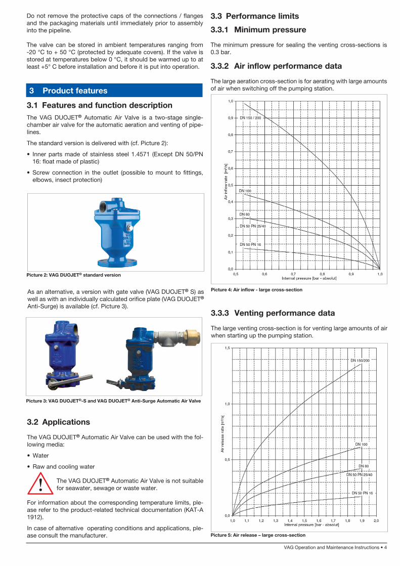
3.1 Features and function descriptionThe VAG DUOJET® Automatic Air Valve is a two-stage single-chamber air valve for the automatic aeration and venting of pipe-lines.
The standard version is delivered with (cf. Picture 2):
• Inner parts made of stainless steel 1.4571 (Except DN 50/PN 16: float made of plastic)
• Screw connection in the outlet (possible to mount to fittings, elbows, insect protection)
Picture 2: VAG DUOJET® standard version
As an alternative, a version with gate valve (VAG DUOJET® S) as well as with an individually calculated orifice plate (VAG DUOJET®
Anti-Surge) is available (cf. Picture 3).
Picture 3: VAG DUOJET®-S and VAG DUOJET® Anti-Surge Automatic Air Valve
3.2 Applications
The VAG DUOJET® Automatic Air Valve can be used with the fol-lowing media:
• Water
• Raw and cooling water
The VAG DUOJET® Automatic Air Valve is not suitable for seawater, sewage or waste water.
For information about the corresponding temperature limits, ple-ase refer to the product-related technical documentation (KAT-A 1912).
In case of alternative operating conditions and applications, ple-ase consult the manufacturer.
3.3.3 Venting performance data
The large venting cross-section is for venting large amounts of air when starting up the pumping station.
3.3 Performance limits
3.3.1 Minimum pressure
The minimum pressure for sealing the venting cross-sections is 0.3 bar.
3.3.2 Air inflow performance data
The large aeration cross-section is for aerating with large amounts of air when switching off the pumping station.
Picture 4: Air inflow - large cross-section
Picture 5: Air release – large cross-section
Do not remove the protective caps of the connections / flanges and the packaging materials until immediately prior to assembly into the pipeline.
The valve can be stored in ambient temperatures ranging from -20 °C to + 50 °C (protected by adequate covers). If the valve is stored at temperatures below 0 °C, it should be warmed up to at least +5° C before installation and before it is put into operation.

VAG Operation and Maintenance Instructions • 5
4.1 Conditions required on site
When installing the pipeline flange it must be horizontal, plane pa-rallel and flush.
Aeration and venting valves should be installed as close as possible to the pipe being vented to avoid long supply lines from collect-ing stagnating water (hygienic problems, higher costs, regular flushing). In addition, long supply lines may result in limited venting function as well as be associated with the risk of free-zing (the supply line or the air valve itself).
In case of mechanical works around the valve causing dirt (e.g. painting, working with concrete etc.), the valve must be protected by adequate covering.
For assembly in drinking water pipelines, suitable sealing mate-rials, lubricants and process materials must be used which are approved for use in drinking water pipelines.
Before putting the valve into operation, clean and purge the corre-sponding pipeline sections.
4.2 Installation location
To ensure the trouble-free function and long service life of the val-ve, several factors have to be taken into account when positioning the valve.
The VAG DUOJET® Automatic Air Valve can be installed in sta-tions, in the open or in chambers.
4 Installation into the pipeline
3.3.4 Air release valve performance data
The small venting cross-section is for venting small amounts of air during operation under full internal overpressure.
Picture 6: Air release – small cross-section
Installation should take place at the high points of the pipeline. For direct installation of the VAG DUOJET® Automatic Air Valve on a standpipe we recommend the use of an orifice plate upstream of the valve. Chamber structures must be built and equipped in accordance with DVGW data sheet W 358.
4.2.1 Installation in pipeline < DN 600
For pipelines < DIN 600 it is wise to use a sufficiently dimensioned venting dome. If not verified in detail, the venting dome can be considered sufficiently dimensioned if its construction height mat-ches the diameter of the pipeline and has the diameter of approxi-mately half the diameter of the pipeline. A central stop valve, an air valve and, if required, a device for manually activated aerating and venting or flushing are required. The central stop valve upstream from the air valve allows it to be installed or dismantled without interrupting operations. Because the air valve stopped by the stop valve is under pressure a vent plug is provided on the air valve to release pressure. In place of a plug, an installed valve operated manually simplifies aeration and venting and can also be used as a flush valve.
Picture 7: Pipeline < DN 600
~ D
N ~ 0,5 DN
1
2
3
1: Venting valve
2: Manually operated air inflow and release, flush
valve
3: Central stop valve
VAG Operation and Maintenance Instructions • 6
4.3 Installation position
The VAG DUOJET® Automatic Air Valve must always be installed in an upright position. If installed in any other position, the manu-facturer cannot ensure the trouble free functioning of the valve or station (see Pic-ture 10 - following page).
4.4 Installation note
Observe the following special installation notes in ac-cordance with the specified hydraulic conditions and installation positions.
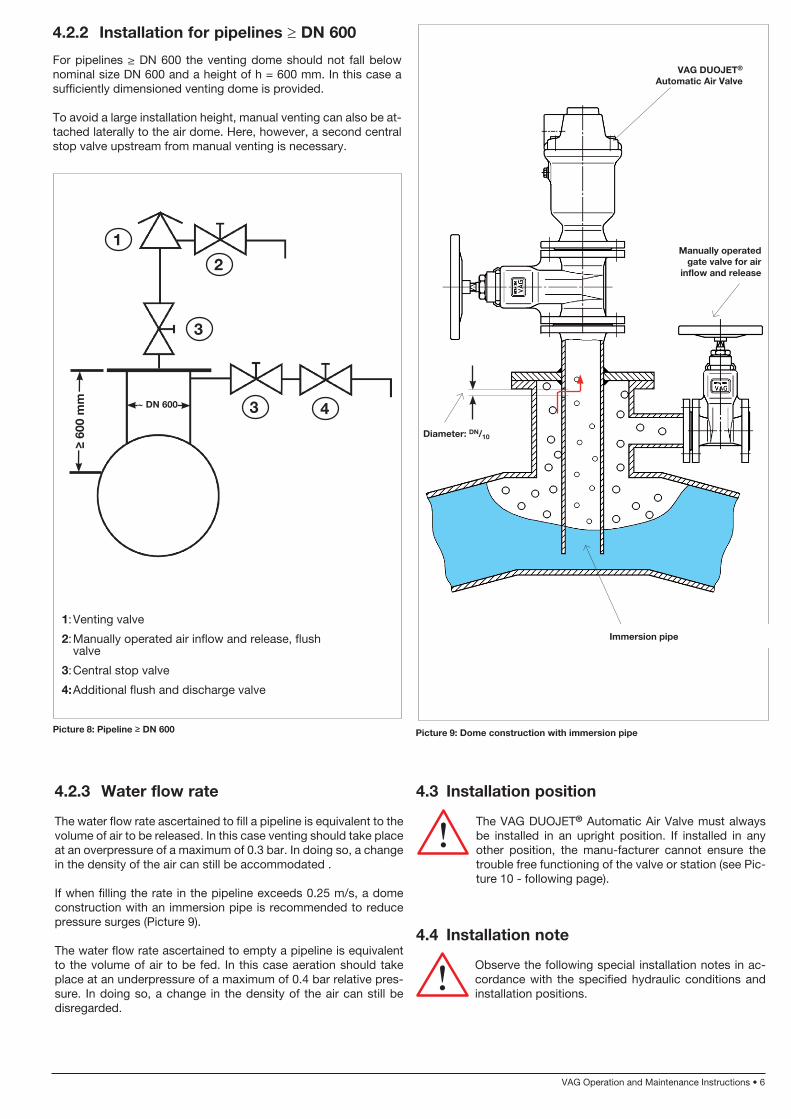
4.2.2 Installation for pipelines ≥ DN 600
For pipelines ≥ DN 600 the venting dome should not fall below nominal size DN 600 and a height of h = 600 mm. In this case a sufficiently dimensioned venting dome is provided.
To avoid a large installation height, manual venting can also be at-tached laterally to the air dome. Here, however, a second central stop valve upstream from manual venting is necessary.
≥ 60
0 m
m ~ DN 600
1
2
3 4
1: Venting valve
2: Manually operated air inflow and release, flush valve
3: Central stop valve
4: Additional flush and discharge valve
4.2.3 Water flow rate
The water flow rate ascertained to fill a pipeline is equivalent to the volume of air to be released. In this case venting should take place at an overpressure of a maximum of 0.3 bar. In doing so, a change in the density of the air can still be accommodated .
If when filling the rate in the pipeline exceeds 0.25 m/s, a dome construction with an immersion pipe is recommended to reduce pressure surges (Picture 9).
The water flow rate ascertained to empty a pipeline is equivalent to the volume of air to be fed. In this case aeration should take place at an underpressure of a maximum of 0.4 bar relative pres-sure. In doing so, a change in the density of the air can still be disregarded.
Picture 8: Pipeline ≥ DN 600 Picture 9: Dome construction with immersion pipe
3
VAG DUOJET®
Automatic Air Valve
Manually operated gate valve for air
inflow and release
Diameter: DN/10
Immersion pipe

VAG Operation and Maintenance Instructions • 7
Permissible
Impermissible
Upright installation position
Picture 10: Installation position of the Automatic Air Valve
90°
<> 90°
4.4.1 Installation position downstream from pumps
If the VAG DUOJET® Automatic Air Valve has to be installed downstream from pumping stations, positioning must take place according to the “ideal” installation position shown in Picture 11.
Picture 11: Installation position downstream from pumps
Impermissible installation position
Ideal installa-tion position
4.4.2 Installation in standpipes
Standpipes result in high flow velocities during the filling process. If the VAG DUOJET® Automatic Air Valve is installed directly on the standpipe there is a risk of the ball closing prematurely.
To prevent premature closing we recommend the installation of a multiple-orifice plate in front of the valve (cf. Picture 12).
4.4.3 Discharging splashing or surge water
When intentionally discharging splashing or surge water via the pipeline it should be cut off slowly downstream of the valve so that no improper suction effect impacts the VAG DUOJET® Auto-matic Air Valve (cf. Picture 13).
Picture 12: Installation position in standpipe
Impermissible ins-tallation position
(risk of suction effect)
Ideal installation position
(elbow and down-pipe separated)
Picture 13: Installation position for splashing or surge water
Multiple-orifice plate

VAG Operation and Maintenance Instructions • 8
4.5 Assembly instructions and fittings
Check the valve for possible damage that it may have suffe-red during transport and storage. Protect the valve against dirt caused on the construction site by adequate covering until ins-tallation. Thoroughly clean the surface of the flange gasket prior to installation.
VAG does not assume any liability for consequential damage caused by dirt, shot-blasting gravel residue etc.
The functional parts should be checked for proper operation prior to installation.
Should the valves be repainted later on, it must be ensured that no paint is applied to the functional parts. The identification plates must not be painted over either. If the equipment is sand-blasted for cleaning prior to installation, these parts must be adequately covered. If solvents are used for cleaning, it must be ensured that the solvents do not destroy the seals of the pipeline or the valve.
For the assembly of the VAG DUOJET® Automatic Air Valve it must be ensured that proper load suspension devices as well as means of transport and lifting devices are available.
When connecting the valve with the pipeline flanges, hexagon bolts and nuts with washers from flange to flange must be used in the through holes.
The bolts and nuts selected by the operator must be appropriate for the pressure, temperature, flange material and the gasket. For connections that contain at least one cast-iron flange it is recom-mended to use bolts with a yield strength not exceeding 240 N/mm².
Fasten the bolts evenly and diagonally to prevent unnecessary tension and the resulting cracks or breaks.
We recommend using steel-reinforced rubber seals to DIN EN 1514-1 Shape IBC. If you use raised face flanges, these seals are mandatory.
5 Set-up and operation of the valve
5.1 Visual inspection and preparation
Before putting the valve and the equipment into operation, per-form a visual inspection of all functional parts. Check whether all bolted connections have been properly fastened.
If there is an upstream stop valve this must be set to the open po-sition so that the VAG DUOJET® Automatic Air Valve can function satisfactorily.
5.2 Function check and pressure test
Warning: The pressure exerted on the closed valve must not exceed its nominal pressure (see technical data sheet KAT 1912-A).
Newly installed pipeline systems should first be thoroughly pur-ged to remove all foreign particles. If residue or dirt particles are present in the pipeline, they may clog the installation while the
pipeline is being purged. This may impair the function of the valve or even block it.
In particular after repair work or upon the commissioning of new equipment, the pipeline system is to be purged again with the val-ve being fully open. If detergents or disinfectants are used it must be ensured they do not attack the valve materials.
6 Maintenance and repair
6.1 General safety instructions
Prior to beginning inspection and maintenance work on the valve, the connection to the pressure carrying pipe-line must be shut off and depressurized via the plug on the valve. Only afterwards may maintenance work on the valve be performed.
After completing the maintenance works and before resuming operation, check all connections for proper fastening and tight-ness. Perform the steps described for initial set-up as described under Section 5 “Set-up and operation”.
Statutory and local provisions as well as the safety and accident prevention regulations must be observed and complied with at all times.
Servicing, maintenance and inspection work as well as the repla-cement of spare parts must only be carried out by qualified staff. The plant operator is responsible for determining the suitability of the staff or for ensuring the relevant qualifications.
In case the operator’s employees do not have the qualifications required, they need to attend a training course. This training course can e.g. be held by VAG Service employees.
In addition to this, the plant operator needs to ensure that all em-ployees have understood these Operation and Maintenance Inst-ructions as well as all further instructions referred to in them.
Protective equipment such as safety boots, safety helmets, gogg-les, protective gloves etc. must be worn during all work requiring such protective equipment or for which such protective equip-ment is prescribed.
Improper or wrong use of the valve should be avoided. Prior to the performance of any work on the valve and equipment it must be ensured that the relevant pipeline section has been depressurised and/or de-energised.
6.2 Inspection and operation intervals
The VAG DUOJET® Automatic Air Valve is virtually maintenance-free.
The valve should however be inspected within a period of one year (DVGW data sheet W 392).
Under extreme conditions of use this inspection interval should be carried out more frequently.
Before any maintenance work is performed on the VAG DUOJET®
Automatic Air Valve, the valve must be shut off by an inspection valve and must be depressurised using the threaded plug 11 (see Section 6.3.1. “Design”).
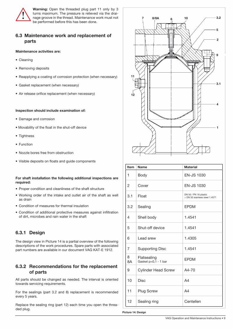
VAG Operation and Maintenance Instructions • 9
Warning: Open the threaded plug part 11 only by 3 turns maximum. The pressure is relieved via the drai-nage groove in the thread. Maintenance work must not be performed before this has been done.
6.3 Maintenance work and replacement of parts
Maintenance activities are:
• Cleaning
• Removing deposits
• Reapplying a coating of corrosion protection (when necessary)
• Gasket replacement (when necessary)
• Air release orifice replacement (when necessary)
Inspection should include examination of:
• Damage and corrosion
• Movability of the float in the shut-off device
• Tightness
• Function
• Nozzle bores free from obstruction
• Visible deposits on floats and guide components
For shaft installation the following additional inspections are required:
• Proper condition and cleanliness of the shaft structure
• Working order of the intake and outlet air of the shaft as well as drain
• Condition of measures for thermal insulation
• Condition of additional protective measures against infiltration of dirt, microbes and rain water in the shaft
6.3.1 Design
The design view in Picture 14 is a partial overview of the following descriptions of the work procedures. Spare parts with associated part numbers are available in our document VAG KAT-E 1912.
6.3.2 Recommendations for the replacement of parts
All parts should be changed as needed. The interval is oriented towards servicing requirements.
For the sealings (part 3.2 and 8) replacement is recommended every 5 years.
Replace the sealing ring (part 12) each time you open the threa-ded plug.
Picture 14: Design
Item Name Material
1 Body EN-JS 1030
2 Cover EN-JS 1030
3.1 Float DN 50 / PN 16 plastic > DN 50 stainless steel 1.4571
3.2 Sealing EPDM
4 Shell body 1.4541
5 Shut-off device 1.4541
6 Lead srew 1.4305
7 Supporting Disc 1.4541
8 8A
Flatsealing Gasket p=0,1 - 1 bar
EPDM
9 Cylinder Head Screw A4-70
10 Disc A4
11 Plug Screw A4
12 Sealing ring Centellen
7
11
2
1
8/8A 6 10 3.2
5
9
3.1
12
4

VAG Operation and Maintenance Instructions • 10
6.3.3 Replacement of the seals (3.2 and 8)
• Unfasten the cylindrical screws (9) crosswise
• Lift off cover (2) of the valve
• The seals, float, shell and shut-off device can now be removed
• The seal (3.2) is attached to the float (part 3.1) by cyanoacrylate adhesive (rapid set adhesive). When replacing the seal, pull it off the float and then glue the new seal to the float.
• For subsequent reassembly, place the shell into the body. Place the float into the shell, insert the seal (part 8) as well as the retaining washer (part 7) into the cover and centre it. Insert the shut-off device into the guide screw (part 6) and place the cover onto the body. Fasten the hexagon socket screws crosswise.
Cylinder screw (9)
M 12 M 16 M 20
30 Nm 10 Nm 20 Nm
Table 1: Cylinder screw tightening torques
Plug (11)
G½“
30 Nm
For all repair and maintenance work, please observe the general safety instructions described in Section 6.1!
7 Trouble-shooting
Table 2: Plug tightening torques
Problem Cause Remedial action
Leaking main air valve
Foreign matter stuck in seat area
Flush valve, possibly disassemble and remove foreign matter
Internal pressure too lowTo achieve tightness internal pressure must be at least 3 m water column. Replace gasket with a low pressure gasket (0.1 - 1 bar)
Deposits from medium on the seat
Open cover, clean seat section
Sealing damagedReplace sealing (recommendation: replacement after a maximum of 5 years) see 6.3.3
Improper installation position Change installation position
Leaky air release orifice
Foreign matter stuck in air release orifice
Flush valve, possibly disassemble and remove foreign matter
Sealing defectiveReplace sealing (recommendation: replacement after a maximum of 5 years) see 6.3.3
Air release orifice rate too smallOperational characteristics were changed
Check layout and operational characteristics, if neces-sary, install special air release orifice with larger release bore
Outlet clogged Insect infestation Clean valve and attach insect protection
6.3.4 Bolt tightening torques
8 How to contact us
Head office
VAG-Armaturen GmbH Carl-Reuther-Str. 1 68305 Mannheim Germany
Telephone: +49 (621) 749-0 Fax: +49 (621) 749-2153
[email protected] http://www.vag-group.com
Service
Our service hotline can be reached 24/7 world-wide. In case of emergency, please contact us by phone.
Service hotline: +49 621 - 749 2222
Service per email: [email protected]

Ed
ition
2 -0
5/20
10
VAG-Armaturen GmbHCarl-Reuther-Str. 168305 MannheimGermanyTel. +49 6 21 749-0Fax +49 6 21 [email protected]