vacuum system - ckd · vsrvv series compact vacuum pad (options newly added) compact vacuum filter...
TRANSCRIPT

CC-828A
Vacuum system componentsNew model and variation available
New 5 models available!
VACUUM SYSTEM
New product

Wide variation meeting different applicationsNEW vacuum system components for wide applications from very small workpieces such as electric part, etc., to large and heavy workpieces used in automobile manufacturing, etc.
Compact designEach component is compactly designed to achieve space saving.
Wide variationWide series and variation available for different applications
Unit and moduleThe core vacuum ejector and vacuum unit is designed with unitization and modularization to save space and facilitate use.
Suction transferring various electric part, semiconductor circuit board,
wafer and DVD, etc.
Assembling and inserting small parts
Transferring liquid crystal panel and glass panel, etc.
Packing can beer and can juice, etc.
Transferring boxes at the physical distribution warehouse
Transferring light, medium and heavy weight workpieces in
automobile manufacturing lines, etc.
Other
Available for transferring, insert positioning and packing, etc.
Vacuum system components
Now available
Intro 1

Model
Vacuum ejectorwith vacuum break
VSY SeriesVSY-*S
VSY-*S-F
VSY-*J
VSY-*J-F
1
9
19
21
25
Atmospheric release with silencer
Atmospheric release with silencerWith filter
Common exhaust
Common exhaustWith filter
VSP-MA*
VSP-MB*
VSP-ME*
Fixed type/top vacuum outlet
Fixed type/side vacuum outlet
Fixed type/direct mount type
VSECV-M3
VSECV-M4
VSECV-M5
VSECV-M6
VSECV- 6A
Port size: M3
Port size: M4
Port size: M5
Port size: M6
Port size: R(c) 1/8
VSRVV-*A*
VSRVV-*B*
VSRVV-*U*
ElbowSupply: joint/output: male thread
ElbowSupply: male thread/output: joint
Elbow union typeSupply: joint/output: joint
VSFJ- 44
VSFJ- 66
Port size: ø4
Port size: ø6
VSP-M* Series
VSPG-*RM*(only pad rubber)
VSFJ Series
VSECV Series
VSRVV Series
Compact vacuum pad(options newly added)
Compact vacuum filtersocket type
Check value
Compactvacuum regulator
Series/product appearance Overview
Model no. Remarks
Series variationPage
• Ejector and vacuum break integrated• Compact/light weight body allows
use in the vacuum piping end.
• Socket shaped inline vacuum filter• This is appropriate for discrete ejector,
etc., not integrating vacuum filter
• If a workpiece is dislocated, vacuum state of workpieces handled with other circuits is held.
• This is applicable for vacuum pads.
• The source pressure and the terminal are controlled.
• When installed between the vacuum valve and vacuum pad, the pressure of each pad is controlled.
• Optional digital display sensor or vacuum gauge is available.
• Pad outer diameter inner diameter: ø0.7 ø0.2, ø1.0 ø0.4, ø1.5 ø0.7 now available
• Conventional vacuum pad holders are downsized to achieve space saving.
Vacuum system componentsNewly added model variation and INDEX
Intro 2

This product is designed and manufactured as a general industrial machine part. It must be handled by an operator having sufficient knowledge and experience in handling.
Use this product in accordance of specifications.Contact CKD when using the product outside the unique specifications range, when using it outdoors, and when using it under the conditions and environment below. Do not attempt to modify or additionally machine the product. Use for special applications requiring safety including nuclear energy, railroad, aviation, ship, vehicle, medical
equipment, equipment or applications coming into contact with beverage or food, amusement equipment, emergency shutoff circuits, press machine, brake circuits, or for safeguard.
Use for applications where life or assets could be adversely affected, and special safety measures are required.
Observe corporate standards and regulations, etc., related to the safety of device design and control, etc.ISO 4414, JIS B 8370 (pneumatic system rules)JPAS 005 (principles for pneumatic cylinder use and selection)Including High Pressure Gas Maintenance Law, Occupational Safety and Sanitation Laws, other safety rule, and organization standards and regulations
Do not handle, pipe, or remove devices before confirming safety. Inspect and service the machine and devices after confirming safety of the entire system related to this product. Note that there may be hot or charged sections even after operation is stopped. When inspecting or servicing the device, turn off the energy source (air supply or water supply), and turn off power
to the facility. Discharge any compressed air from the system, and pay enough attention to possible water leakage and leakage of electricity.
When starting or restarting a machine or device that incorporates pneumatic components, make sure that the system safety, such as pop-out prevention measures, is secured.
Observe warnings and cautions on the pages below to prevent accidents.
Safety precautionsAlways read this section before starting use.
The safety cautions are ranked as "DANGER", "WARNING" and "CAUTION" in this section.
WARNING
When designing and manufacturing a device using CKD products, the manufacturer is obligated to check that device safety mechanical mechanism, pneumatic control circuit, or water control circuit and the system operated by electrical control that controls the devices is secured.It is important to select, use, handle, and maintain the product appropriately to ensure that the CKD product is used safely.Observe warnings and precautions to ensure device safety.Check that device safety is ensured, and manufacture a safe device.
DANGER: When a dangerous situation may occur if handling is mistaken leading to fatal or serious injuries, or when there is a high degree of emergency to a warning.
WARNING: When a dangerous situation may occur if handling is mistaken leading to fatal or serious injuries.
CAUTION: When a dangerous situation may occur if handling is mistaken leading to minor injuries or physical damage.
Note that some items described as "CAUTION" may lead to serious results depending on the situation.In any case, important information that must be observed is explained.
1
2
3
4
5
1
2
1
2
3
4
Intro 3
Setting & Selection
WARNINGUse this product in accordance with the specifications range.Products in this catalog are for use only in a compressed air system. Use with pressure or temperature exceeding the specification range may result in damage or operation faults.(Refer to the specifications.)Consult with CKD when using fluids other than compressed air
WARNINGAlways take necessary measures to prevent harm to operators or objects if this product fails.
CAUTIONUnderstand compressed air features before designing a pneumatic circuit.• The same functions as mechanical, hydraulic, and electrical
methods cannot be anticipated if instantaneous service interruption and holding are required during an emergency stop.
• Pop-out, air discharge, or leakage due to air compression and expansion could occur.
• Design a circuit as the compressed air in the system can be exhausted.
Decide the method of lubricating pneumatic components, and provide correct maintenance.• Is the product lubricating type ?• Is the product pre-lubricated ?
Check leakage current to prevent malfunction caused by leakage current.• When used for the programmable control, etc., leakage current
could result in malfunctions.
CAUTIONSmall leaks that do not affect performance are tolerated because this product is used with compressed air.Contact CKD when no leaks are tolerable.
1. Specifications confirmation
WARNINGDo not use the product where the product is exposed to direct-sunlight or may come in contact with water or oil.
Do not use this product in a corrosive environment.Use in the environment like this could result in damage or malfunction.
Consult with CKD if ozone could occur in supplied air.(Ozone proof products available)
If ambient temperature is less than 5˚C, moisture in the circuit could freeze and lead to operation faults, etc. Remove moisture to prevent freezing.
Avoid use in ozone occurring environments.
CAUTIONConfirm that the product will withstand the working environment.• This product cannot be used in environments where functional
obstacles could occur.Such environments include those reaching high temperatures, having a chemical atmosphere, or involving the presence of chemicals, vibration, humidity, moisture, coolant, or gas or where ozone is generated.
CAUTIONEnsure space around the pneumatic component for installation, removal, wiring, and piping work.
CAUTIONIndicate the maintenance conditions in the device's instruction manual.• The product's function can drop markedly with working status,
working environment, and maintenance, and can prevent safety from being attained. With correct maintenance, the product functions can be used to the fullest.
4. Working environment
5. Ensuring space
6. Stipulation in instruction manuals
2. Safety designing
3. Design per application
Intro 4

Instillation & Adjustment
WARNING
Do not remove the pneumatic component package or the piping port seat cap until just before piping the product.• If the piping port cap is removed from the piping port before
piping work is started, foreign matter could enter the pneumatic component from the piping port and result in faults or faulty operation.
Do not install pneumatic components with a method that supports with pipes.
Do not remove the dust-proof seal on the piping port until just before piping the product.• If the seal is removed from the piping port before piping work
is started, foreign matter could enter and result in faults or faulty operation.
After connecting piping, check pipe connections for air leaks before supplying compressed air.• Apply a leakage detection agent on pipe connections with a
brush, and check for air leaks. Check that the leak detection agent does not get on the plastic bowl because the plastic bowl could break and cause a hazard.
When connecting pipes, wrap sealing tape in the opposite direction from threads starting 2 mm inside from the end of piping threads.• If sealing tape protrudes from pipe threads, it could be cut when
screwed in. This could cause the tape to enter the solenoid valve and lead to faults.
When using a liquid sealant, check that it does not adhere to the plastic bowl, because it could damage the plastic bowl and cause a hazard.
Check that the pipe connected to the pneumatic component is not dislocated due to vibration, loosening, or pulling.• Piping dislocation generates a hazardous state.
Observe the following precautions when using nylon tubes or urethane tubes for piping material.• Use a flame resistance tube or steel pipe when using in an
environment where spatter could scatter.
1. Installation
• Use a hydraulic hose when piping is to be used for hydraulic pressure.
• When using the standard push in joint on the spiral tube, fix the base of the tube with a hose band, or the tube could rotate and reduce holding performance.
• Use a spigot joint for high-temperature fluid. Push-in joints cannot be used.
Pipe so that piping connection does not deviate by the device's movement, vibration, tension, etc.
Always flush just before piping pneumatic component.• Foreign matter entering during piping must not enter pneumatic
components.
Apply adequate torque when connecting pipes to prevent air leak and to protect thread.• Tighten by hand at first, then use a tool, so as screw thread
is not damaged.
Install an air filter just before the pneumatic component in the circuit.
When supplying compressed air for the first time after connecting pipes, do not apply high pressure suddenly.• Piping connection could be dislocated or the piping tube fly
off, leading to accidents.• Caution: If compressed air is supplied too slowly, sealing
pressure may not be generated by the sealing mechanism in the solenoid valve. This can lead to air leaks.
Quality of air• Use CKD clean air system components in accordance with
applications.• Use compressed air that does not contain oxidized oil, tar,
carbon, etc., from the air compressor.• Use compressed air that does not contain solid foreign matter.
4. Pneumatics pressure source
2. Pre-operation confirmations
3. Piping
0.3 to 0.6
1 to 1.5
3 to 5
6 to 8
13 to 15
16 to 18
19 to 40
41 to 70
(Recommended value)
M3
M5
Rc1/8
Rc1/4
Rc3/8
Rc1/2
Rc3/4
Rc1
Set screw Tightening torque N·m
Intro 5

During use & Maintenance
WARNING
The pneumatic component must be disassembled and assembled by a qualified worker.• The grade not less than Pneumatics technique certification
grade 2 is required.
If pneumatics are assembled or disassembled, read the instruction manual of the product very well and understand the contents before disassembling and assembling the product.• Personnel must be fully familiar with pneumatic component
structure and operational principles and safety requirements.
Before servicing the product, turn power OFF, stop the compressed air supply, and check that there is no residual pressure.• This is a requirement for ensuring safety.
2. Maintenance & Inspection1. Assembling & disassembling
Intro 6

Intro 7
Read this section before selecting and using CKD products.
WARNING01. If drop of workpiece could result in hazardous situations, take safety measures such as drop
prevention.
02. Do not use for applications in which a pressure of 0.1 MPa or more is constantly applied to thevacuum circuit. The vacuum component is not explosion-proof and this application could damagethe main unit.
03. Monitor drops in vacuum pressure caused by problems in the supply air or supply power. Theworkpiece could fall if suction pressure drops.
04. When more than one pad is piped to one ejector with the vacuum circuit, a suction fault with onepad may cause the other pad to separate due to a drop in vacuum pressure.
05. Do not use for applications that plug the ejector exhaust port or in which exhaust resistance rises,or faults such as inability to generate vacuum or drops in vacuum pressure could occur.
06. Do not use this product under the following conditions: corrosive gas, flammable gas, explosivegas, chemicals, sea water, or moisture. Do not collect these substances with this product.
07. Add a protective cover if the product is exposed to direct sunlight.
08. Regularly service and inspect the ejector silencer element and vacuum filter element.Performance could be compromised or problems occur if these are clogged.
09. Read the explanation of vacuum ejector replacement thoroughly before replacing it.
10. Confirm instructions in this manual and on the main unit before piping ejector ports. Incorrectpiping could damage the main unit.
11. Supply clean air, from which drainage and dirt has been eliminated, to the ejector. Do not oil witha lubricator. Impurities and oil in compressed air could cause operation faults and a drop inperformance.
12. Do not apply strong tension or excessively bend leads, or they may break.
13. If the product has a lock nut, securely tighten the nut by hand instead of using a tool. The lock nutor main unit could be damaged if the lock nut is tightened with a tool.If the lock nut is not tightened precisely, it could loosen and change initial settings.
14. If the product has a resin body which rotates, do not forcibly shake or rotate the product. Themain unit could be damaged or leaks could result.
Common precautions for vacuum system components!
!

Intro 8
CAUTION1. The ejector's supply pressure (value specified in this manual) is that for when the ejector is
operating. Ensure that the value specified in this manual is used if pressure drops. If the specifiedvalue is not met, problems could occur such as abnormal noise generated by the ejector at aspecific supply pressure or characteristics could become unstable.
2. A value three times the nozzle diameter section is set as the guide for the effective sectional areaof ejector supply pressure. Performance may be compromised if the supply flow is low.
3. Keep vacuum piping as short as possible, or use a larger inner bore. If piping is too long or theinner bore too narrow, response at suction or separation could be compromised and the requiredsuction flow not ensured.
!

Intro 9
Read this section before selecting and using CKD products.
WARNING
1. Before setting the pad diameter, number of pads, and pickup position, read and comprehend thesection on theoretical suction in this manual. Provide sufficient allowance for settings.
2. See selection in this manual and select the pad material based on the working environment and use.
3. Read features of pads given in this document. Some pad shapes (types) are more suitable for theproduct and product shape to be picked up.
4. The spring holder is more suitable when the height of the products to be picked up varies, or whenpicking up a product easily damaged by an external force. Confirm the spring force and stroke givenin these specifications before using.
5. The spring holder has a sliding section so the lateral force must be minimum. Failure to observe thiscould result in a drop in the holder life or faulty operation.
CAUTION
1. If hazardous situations could occur if the workpiece drops, take safety measures such as dropprevention.
2. Securely fix the pad holder when installing it. Loosening could cause problems or hazards.
3. Take care when rotating transfer with a pad fixed with a screw. The rotation could cause the screw toloosen, and result in problems or hazards.
4. Conduct regular maintenance and inspection. Leaks in the vacuum circuit, clogging, pad wear,cracks, deterioration, biting at the pad holder's sliding section, and loosening at other connectionscould result in problems.
5. Note acceleration, impact and wind pressure when transferring and moving with pads. The partcould fall off during transfer.
!
!
Common precautions for vacuum pad!

Intro 10
6. When replacing the pad, check the vacuum pad structure drawing given in this manual and see therecommended tightening torque below. Using an appropriate tool, tighten the pad with the holder'sexternal hexagon section so that it does not loosen.
•Table. Recommended tightening torque
Pad thread size (mm) Tightening torqueM4 0.7 0.9 to 1.1N·mM6 1 2 to 2.7N·m
M10 1.5Pad diameter: ø60mm Pad diameter: ø80mm and ø100mm
5 to 6N·m 8.3 to 9.3N·mM20 2 9 to 10N·m

Intro 11
MMMMEEEEMMMMOOOO

1
Vacuum ejector with vacuum break
VSY Series
Specifi cations
Working fl uid Air
Working pressure range 0.3 to 0.7MPa
Ambient temperature range 5 to 50˚C
Lubrication Not required
The compact, lightweight design enable use at the end of the vacuum pipe.A high-speed suction and break cycle is possible by installing a shutoff valve.
A function for discharging break air to the ejector has been added.The vacuum break is more accurate than the conventional discrete ejector.
Integrated ejector and vacuum breaks.Vacuum generation and break air are toggled by turning the air supply to the ejector on and off.Refer to "Applications" on the following page.
Specifi cations of vacuum fi lter
Working fl uid Air
Working pressure range - 100 to 0kPa
Filtration accuracy 10µm
Ambient temperature range 0 to 60˚C
Filtration area Port size ø4: 0.8cm2
Port size ø6: 1.1cm2
Features
Integrating the ejector and vacuum breakrealizes a high-speed suction and break cycle.

2
How to use
Connect the P and PD ports with a check valve (optional), and use residual pressure between the check valve and PD port as break air.The break air fl ow is adjusted with the break air fl ow adjustment needle, and break time is adjusted with the length of the tubing connecting the check valve and PD port.
<Example 1>
Vacuum generator valve
Check valve
P portP portPD portPD port
Break air fl ow control needleBreak air fl ow control needle
Shut off valveShut off valve
FilterFilter
V port
EjectorEjector
Silencer or common exhaustSilencer or common exhaust
Circuit diagram
If the workpiece must be released instantly with vacuum break air, break air pressure and fl ow are adjusted. Caution is required because the workpiece could be blown off. The above illustration shows different pressures used for the air supply for vacuum generation and for vacuum break, such as when pressure for vacuum break air is set low. Note that the supply pressure for vacuum pressure is the same or greater than the supply pressure for vacuum breaks.The vacuum break air fl ow is adjusted with the break air fl ow adjustment needle, and break time is adjusted with the vacuum break valve, etc.
<Example 2>
Vacuum generator valve
P portP portPD portPD port
Break air fl ow control needleBreak air fl ow control needle
Shut off valveShut off valve
FilterFilter
V port
EjectorEjector
Silencer or common exhaustSilencer or common exhaust
Circuit diagram
Valve for vacuum break
RegulatorRegulator

3
Structural drawing
No.
(1)
(2)
(3)
(4)
(5)
(6)
(7)
(8)
(9)
(10)
(11)
(12)
(13)
(14)
(15)
(16)
(17)
(18)
(19)
(20)
(21)
Part name
End plug
Top plug
Break needle
Plug 2
Sleeve
Nozzle piston
Diffuser spool
Resin
Spool packing seal
Diffuser spring
Silencer element
Cartridge
Guide ring
Rubber sleeve
Release ring
Y packing seal
O ring
Lock nut
Spring connector pin
Lock jaw
Tube
Material
Brass and electroless nickeling
Brass and electroless nickeling
SUS 303 or equivalent
Brass and electroless nickeling
Brass and electroless nickeling
Brass and electroless nickeling
Brass and electroless nickeling
PBT glass 15%
H-NBR
Stainless steal
PVF
Brass and electroless nickeling
NBR
POM
NBR
NBR
Aluminum
Stainless steal
Stainless steal
Urethane or nylon
(1)
(2)
(3)(4)
(5)
(6)
(7)
(8)
(9)
(10)(11)
(12)
(16)
(17)
(18)
Structural drawing of vacuum fi lter
No.
(1)
(2)
(3)
(4)
(5)
(6)
(7)
(8)
Part name
Resin
Lock jaw
Guide ring
Release ring
Tube
Rubber sleeve
Element holder
Filter element
Material
PP
Stainless steal
Brass and electroless nickeling
POM
Urethane or nylon
NBR
POM
PVF
(1)(2) (3)
(4)(5)
(6)(7)(8)
(21)
(20)(14)
(13)(15)
(19)

4
How to order
H
L
E
High vacuum/medium flow rate type
Medium vacuum/large flow rate type
High vacuum/small flow rate type
(A) Vacuum characteristics
(B) Nozzle diameter
(C) Vacuum port (V)
(E) Break air supply port (PD)
(D) Air supply port for vacuum occurrence (P)
(F) Exhaust port (EX)
(G) Vacuum filter
(A) Vacuum characteristics
Symbol Descriptions
Note on model no. selection
VSY H 6 F6 6 S07
44M
66M
For VSY-*444*
For VSY-*666*
(A) Port size(A) Port size
Symbol Descriptions
VSY F
05
07
ø0.5
ø0.7
(B) Nozzle diameter
4
6
ø4 push-in joint
ø6 push-in joint
(C) Vacuum port (V) Note 1
4
6
ø4 push-in joint
ø6 push-in joint
(D) Air supply port to generate vacuum (P) Note 1
4
6
ø4 push-in joint
ø6 push-in joint
(E) Break air supply port (PD) Note 1
S
J
Atmospheric release with silencer
Common exhaust
(F) Exhaust port (EX)
Blank
F
Without
With vacuum filter
(G) Vacuum filter
Note 1: Only 444 or 666 are selectable for C, D, and E combinations.
44M
VSY B
•Vacuum ejector with vacuum break
•Replacement vacuum filter
•Bracket
•Dedicated part

5
Max. 33
Min. 30.127.3
12.5 5.3
3-øD11
ø10.5 24.5
B
19.5
C1
2-C2
F17
2-ø3.2
V
PPD
EXH
WARNING1. Read this manual carefully before piping the VSY vacuum ejector. Incorrect piping could result in injury or damage.2. The fi lter is made of PP, so resin deteriorates if subjected to direct sunlight or ultraviolet rays.
CAUTION1. Read this manual carefully to understand adjustment of the break air fl ow and break time.2. The VSY vacuum ejector vacuum fi lter cannot be replaced in an element. When replacing for maintenance and inspection, etc., it must be replaced in a fi lter.3. When using different pressures for vacuum generation and vacuum break supply air, set vacuum break supply air pressure lower than vacuum generation supply
pressure.If higher than the air supply for vacuum generation, leaks could occur.
4. When using the following piping , break air from the check valve is led in and discharged from the V port until the shutoff valve switches completely over.
Model no.Tube outer
diameterøD
B F C1 C2Nozzle
diameter
Rated pressure
(MPa)
Ultimate vacuum(-kPa)
Suction fl ow
( /min(ANR))
Consumption fl ow
( /min(ANR))
Weight (g)
VSY-H05-444S 4 45.1 10.7 11.2 11.30.5
0.5
90 7 11.519
VSY-H05-666S 6 48 11 11.9 11.8 19.5VSY-H07-444S 4 45.1 10.7 11.2 11.3
0.7 92 12.5 2319
VSY-H07-666S 6 48 11 11.9 11.8 19.5VSY-L05-444S 4 45.1 10.7 11.2 11.3
0.566
12 11.519
VSY-L05-666S 6 48 11 11.9 11.8 19.5VSY-L07-444S 4 45.1 10.7 11.2 11.3
0.718
2319
VSY-L07-666S 6 48 11 11.9 11.8 21 19.5VSY-E05-444S 4 45.1 10.7 11.2 11.3
0.50.35 90
3 819
VSY-E05-666S 6 48 11 11.9 11.8 19.5VSY-E07-444S 4 45.1 10.7 11.2 11.3
0.7 9 1719.5
VSY-E07-666S 6 48 11 11.9 11.8 20
Circuit diagram
P portP portPD portPD port
Break air fl ow control needleBreak air fl ow control needle
Shut off valve
V port
EjectorEjector
SilencerSilencer
Vacuum control valveP port
PD portPD portV port
Dimensions
VSY-*S

6
Max. 33
Min. 30.127.3
12.5 5.3
3-øD11
ø10.5 24.5
B
19.5
C1
2-C2
F17
2-ø3.2
V
PPD
EXH
0
10
20
30
40
50
60
70
80
90
100
0.1 0.2 0.3 0.4 0.5 0.6 0.7
Supply pressure (MPa)
Ulti
mat
eva
cuum
(-kP
a)
VSY-*05 VSY-*07
0
10
20
30
40
50
60
70
80
90
100
0.1 0.2 0.3 0.4 0.5 0.6 0.7
Supply pressure (MPa)
Vac
uum
arriv
alsp
eed
(-kP
a)
0
5
10
15
20
25
30
35
40
0
10
20
30
40
50
60
70
80
Hty
peul
timat
eva
cuum
Ety
peul
timat
eva
cuum
Ety
peul
timat
eva
cuum
H type ultimate vacuum
Lty
peul
timat
eva
cuum
Lty
peul
timat
eva
cuum
H type suction flowH type suction flow
L type suction flow L type suction flow
E type suction flow E type suction flow
Consumption flow
Consumption flow
Flo
w(
/min
.(A
NR
))
Flo
w(
/min
.(A
NR
))
VSY-*S-F
Circuit diagram
P portP portPD portPD port
Break air fl ow control needleBreak air fl ow control needle
Shut off valve
FilterFilter
V port
EjectorEjector
SilencerSilencer
Model no.Tube outer
diameterøD
B F C1 C2Nozzle
diameter
Rated pressure
(MPa)
Ultimate vacuum(-kPa)
Suction fl ow
( /min(ANR))
Consumption fl ow
( /min(ANR))
Weight (g)
VSY-H05-444S-F 4 60 34.1 11.2 11.30.5
0.5
90 7 11.520.5
VSY-H05-666S-F 6 63.1 34.4 11.9 11.8 21.5VSY-H07-444S-F 4 60 34.1 11.2 11.3
0.7 92 12.5 2320.5
VSY-H07-666S-F 6 63.1 34.4 11.9 11.8 21.5VSY-L05-444S-F 4 60 34.1 11.2 11.3
0.566
12 11.520.5
VSY-L05-666S-F 6 63.1 34.4 11.9 11.8 21.5VSY-L07-444S-F 4 60 34.1 11.2 11.3
0.718
2320.5
VSY-L07-666S-F 6 63.1 34.4 11.9 11.8 21 21.5VSY-E05-444S-F 4 60 34.1 11.2 11.3
0.50.35 90
3 820.5
VSY-E05-666S-F 6 63.1 34.4 11.9 11.8 21.5VSY-E07-444S-F 4 60 34.1 11.2 11.3
0.7 9 1721
VSY-E07-666S-F 6 63.1 34.4 11.9 11.8 22
Vacuum characteristics

7
Max. 33Min. 30.127.3
12.5 5.33-øD11
ø10.5 ø624.5
B30
.611
.9C
1
2-C
2F
17
2-ø3.2
V
PPD
EXH
VSY-*J
Model no.Tube outer
diameterøD
B F C1 C2Nozzle
diameter
Rated pressure
(MPa)
Ultimate vacuum(-kPa)
Suction fl ow
( /min(ANR))
Consumption fl ow
( /min(ANR))
Weight (g)
VSY-H05-444J 4 55.7 10.7 11.2 11.30.5
0.5
90 7 11.523
VSY-H05-666J 6 58.6 11 11.9 11.8 23VSY-H07-444J 4 55.7 10.7 11.2 11.3
0.7 92 12.5 2323
VSY-H07-666J 6 58.6 11 11.9 11.8 23VSY-L05-444J 4 55.7 10.7 11.2 11.3
0.566
12 11.522.5
VSY-L05-666J 6 58.6 11 11.9 11.8 23VSY-L07-444J 4 55.7 10.7 11.2 11.3
0.718
2322.5
VSY-L07-666J 6 58.6 11 11.9 11.8 21 23VSY-E05-444J 4 55.7 10.7 11.2 11.3
0.50.35 90
3 823
VSY-E05-666J 6 58.6 11 11.9 11.8 23VSY-E07-444J 4 55.7 10.7 11.2 11.3
0.7 9 1723
VSY-E07-666J 6 58.6 11 11.9 11.8 23.5
Circuit diagram
P portP portPD portPD port
Break air fl ow control needleBreak air fl ow control needle
Shut off valve
V port
EjectorEjector
EX portEX port

8
Max. 33Min. 30.127.3
12.5 5.33-øD11
ø10.5 ø624.5
B30
.611
.9C
1
2-C
2F
17
2-ø3.2
V
PPD
EXH
BC
L
øD
1ø
P
øD
2
Vacuum ejector side port Workpiece side port
15
1.2
(23)
17
29.2
30.2
(10.4)
9.2
4
2-ø3.5
2-ø3.5
VSY-*J-F
VSY-F
Model no.Tubeouter
diameterøD1
Applicable joint diameter
øD2B L C øP
Filtration area(cm2)
Weight(g)
VSY-F-44M 4 4 35 21.8 11.3 8 0.8 1.5VSY-F-66M 6 6 35.4 22 11.8 10.5 1.1 2.5
Circuit diagram
P portP portPD portPD port
Break air fl ow control needleBreak air fl ow control needle
Shut off valve
FilterFilter
V port
EjectorEjector
EX portEX port
Model no.Tube outer
diameterøD
B F C1 C2Nozzle
diameter
Rated pressure
(MPa)
Ultimate vacuum(-kPa)
Suction fl ow
( /min(ANR))
Consumption fl ow
( /min(ANR))
Weight (g)
VSY-H05-444J-F 4 60 34.1 11.2 11.30.5
0.5
90 7 11.524
VSY-H05-666J-F 6 63.1 34.4 11.9 11.8 25VSY-H07-444J-F 4 60 34.1 11.2 11.3
0.7 92 12.5 2324
VSY-H07-666J-F 6 63.1 34.4 11.9 11.8 25VSY-L05-444J-F 4 60 34.1 11.2 11.3
0.566
12 11.524
VSY-L05-666J-F 6 63.1 34.4 11.9 11.8 25VSY-L07-444J-F 4 60 34.1 11.2 11.3
0.718
2324
VSY-L07-666J-F 6 63.1 34.4 11.9 11.8 21 25VSY-E05-444J-F 4 60 34.1 11.2 11.3
0.50.35 90
3 824
VSY-E05-666J-F 6 63.1 34.4 11.9 11.8 25VSY-E07-444J-F 4 60 34.1 11.2 11.3
0.7 9 1724.5
VSY-E07-666J-F 6 63.1 34.4 11.9 11.8 25.5
VSY-B

9
Compact vacuum pad
VSP Series (options newly added)
Compact vacuum padAttaching the ø0.7 to ø4 mm diameter pad has been changed from conventional insertion to placedFor the ø6 to ø30mm pad diameter, the existing vacuum pad is used and only the holder has been downsized.
Compact vacuum pad holderThe holder (A, B, E) for the existing vacuum pad has been downsized, saving space.As with the conventional method, the pad is replaced without removing the holder from equipment.The aluminum element (conventionally brass) lightens parts weight.
Features
Pad O.D. I.D.: ø0.7 ø0.2, ø1.0 ø0.4, ø1.5 ø0.7mm are added.New lightweight material to match downsized pad holder

10
MA
MB
ME
Fixed type vacuum outlet top
Fixed type vacuum outlet side
Direct mount type fixed type (pad shape: RM or P only)
(A) Compact holder shape
(B) Pad size
(C) Pad shape
(D) Pad material
(A) Compact holder shapeSymbol Descriptions
VSP 2 VN
Refer to separate table 1.
(B) Pad size
RM
R
A
S
B
W
E
L
LB
K
P
Standard type (compact type)
Standard type (general type)
Standard type (deep type)
Sponge type
Bellows type
Multistage bellows type
Oval type
Soft type
Soft bellows type
Nonskid type
Thin type
(C) Pad shape
N
S
U
F
NH
FS
SE
E
G
Blank
Nitrile rubber
Silicon rubber
Urethane rubber
Fluoro rubber
Oil resistance NBR
Fluoro silicon
Antistatic silicon rubber
Cloroplane rubber
(D) Pad material
2
4
4T
6T
M3
M5
(E) Port size and shape
V
Blank
With check value
None
(F) Check value Note 1
Symbol
Symbol
0.7
ø0.7
8
ø8
1
ø1
10
ø10
1.5
ø1.5
15
ø15
2
ø2
20
ø20
3
ø3
25
ø25
4
ø4
30
ø30
6
ø6
Pad size
4mm
5mm
6mm
8mm
10mm 20mm 30mm
Pad size
RM R A S B W E L
RM R A S B W E L LB K P
LB K PPad shape
Pad
siz
e
Sym
bo
l
MA RM0.7
VSPG NRM0.7
Pad shape
(E)Port size and shape
(F)Checkvalue
0.7
1
1.5
2
3
4
6
8
10
15
20
25
30
4 10
4 20
4 30
5 10
5 20
5 30
6 10
6 20
6 30
8 20
8 30
Pad diameter(mm)
Pad diameter(mm)
4 20
5 20
6 20
8 20
4 10
5 10
6 10
-
4 30
5 30
6 30
8 30
Antistatic butadiene rubber (low-resistance)Food sanitary regulations compliant NBR
ø1.8 push-in joint Note 2
ø4 push-in joint
ø4 barbed joint
ø6 barbed joint
M3 0.5 (compact holder shape: only ME)
M5 0.8 (compact holder shape: only ME)
•Compact vacuum pad
•Only compact pad rubber/standard type (RM)
Separate table 1.1
Separate table 1.2 (pad shape: oval type)
Table of pad size and pad shape combinations
Note on model no. selectionNote 1: See the list of target vacuum pads (page 23) for
applicable pad sizes and shapes for this option.Note 2: Use the air fiber clean EH series or NIHON PISCO
CO., LTD. polyurethane tubing UB01810 series for applicable tubing.
How to order Refer to the model No. fi eld on the Dimensions page (pages 12 to 18) for details on type No. combinations.

11
0
0.2
0
0.4
0.8
1.4
1.2
0.6
1.0
20 40 60 80 100
ø3
ø4
ø2
ø1.5
ø1ø0.7
Degree of vacuum (-kPa)
The
oret
ical
suc
tion
forc
e (N
)
Pad
dia
met
er (
mm
)
Pad diameter: ø0.7mm to ø4mm Pad diameter: ø6mm to ø30mm
0
20
10
0
40
70
60
50
30
80
20 40 60 80 100
ø10
ø15
ø20
ø30
ø8ø6
Degree of vacuum (-kPa)
The
oret
ical
suc
tion
forc
e (N
)
Pad
dia
met
er (
mm
)
AAAWARNING
1. The compact vacuum pad holder is smaller and lighter than the conventional vacuum pad holder, so withstand load strength is not as high. When setting the load, provide suffi cient margin and check on the actual machine.
2. When replacing the vacuum pad, check the vacuum pad confi guration diagram, follow the recommended tightening torque below, use appropriate tools when tightening, and check that no looseness exists.
CAUTION1. When using an antistatic specifi cation vacuum pad, the metal plate, etc., onto which the vacuum pad holder is installed must have measures to release electrostatic
discharge. Failure to provide such measures means that electrostatic discharge accumulates in the vacuum pad.2. The standard general-purpose vacuum pad VSP-*1R* to *4R* cannot be installed on the compact vacuum pad holder. These pads are compatible only with the
standard vacuum pad holder.3. When the compact vacuum pad with diameter ø0.7, ø1, or ø1.5 mm is installed, check that a load exceeding 0.4(N) is not applied on the lip during suction. If an
excessive load is applied on the lip, the inner diameter of the pad could be crushed by the rubber's elasticity. The workpiece may not be picked up or the suction confi rmation signal could malfunction.
4. The air fi ber antistatic UP-9402 series or air fi ber for barbed joint UP-9102 series cannot be used with the port size ø1.8 push-in joint.Recommended applicable tubing: Use the air fi ber clean EH series or NIHON PISCO CO., LTD. polyurethane tubing UB01810 series for the applicable tubing.
3. When installing the compact vacuum pad holder for partitions in the actual machine, follow the recommended tightening torque below, tighten with appropriate tools, and check that no looseness exists.
Table: Recommended tightening torque for partition installing nut Thread size Tightening torque M4×0.7 1 to 1.2N·m M5×0.5 1.5 to 2N·m M6×0.75 2 to 3N·m M8×0.75 2.5 to 3.5N·m M10×1 5 to 7N·m
Theoretical suction force
Table: Recommended tightening torque when replacing vacuum pad Thread size Tightening torque M4×0.7 0.9 to 1.1N·m M6×1 2 to 2.7N·m

12
B8 2-
2
C
øDø6
2-Hex. 7
M5 0.8
C
2-2
12B
øD
2-H
M
C
2-T
L2
B
øD
2-H1
H2
M
M4 0.7
VSP-MA0.7 (push-in joint type)
VSP-MA6 (push-in joint type)
VSP-MA10 (push-in joint type)
Model no.Pad outer diameter
Tube outer diameterøD
B CWeight
(g)Standard typeSymbol: RM
VSP-MA***-2 0.7 to 4 1.8 15.9 8.4 1.8* For total length with the pad installed, refer to the Vacuum Componets General Catalog and add corresponding pad dimension to dimension B.
Model no.Pad outer diameter Tube outer
diameterøD
B C MOpposite side
HWeight
(g)Standard typeSymbol: R
Type for thin oneSymbol: P
VSP-MA***- 2 6,8 8 to 20 1.8 14.1 8.4 M6×0.75 8 2* For total length with the pad installed, refer to the Vacuum Componets General Catalog and add corresponding pad dimension to dimension B.
Model no.Pad outer diameter Tube
outer diameter
øDB L C M
Opposite sideH
Weight (g)
Standard typeSymbol: R, A
Bellows typeSymbol: B
Multistage bellows typeSymbol: W
Soft typeSymbol: L
Soft bellows type
Symbol: LB
Nonskid typeSymbol: K
VSP-MA***-4 10, 15 10 10 4 to 15 6 to 15 10 4 21 16 11.2 M10×1 12 7.7*1. For total length with the pad installed, refer to the Vacuum Componets General Catalog and add corresponding pad dimension to dimension B.*2. Soft and soft bellows types are available if the adaptor is used.
Dimensions

13
10.9
2-3
1.4
163.
422
.4
ø4
2-Hex. 12
Hex. 10
M6 1
M10 1
C
2-2
8
B
øD
2-H
M
C
2-2
82
B
øD
2-H
M
ø6
VSP-MA20 (push-in joint type)
VSP-MA0.7 (barbed joint type)
VSP-MA6 (barbed joint type)
Model no.Pad outer diameter
Weight(g)
Standard typeSymbol: R,A
Sponge typeSymbol: S
Bellows typeSymbol: B
Multistage bellows typeSymbol: W
Oval typeSymbol: E
Soft typeSymbol: L
Soft bellows type
Symbol: LB
Nonskid typeSymbol: K
VSP-MA***- 4 20 to 30 10 to 30 20, 30 20, 30 All size 20, 30 20 20, 30 13*1. For the total length with the pad installed, refer to the Vacuum Componets General Catalog and add corresponding pad dimension to holder dimension 22.1.*2. Soft and soft bellows types are available if the adaptor is used.
Model no.Pad outer diameter
Tube O.D.×I.D.øD
B C MOpposite side
HWeight
(g)Standard typeSymbol: RM
VSP-MA***- 4T 0.7 to 4 4×2.5 15 7 M5×0.5 7 1.3* For total length with the pad installed, refer to the Vacuum Componets General Catalog and add corresponding pad dimension to dimension B.
Model no.Pad outer diameter
Tube O.D.×I.D.øD
B C MOpposite
sideH
Weight(g)
Standard typeSymbol: R
Thin typeSymbol: P
VSP-MA***- 4T 6, 8 8 to 20 4×2.5 17 7 M5×0.5 7 1.6* For total length with the pad installed, refer to the Vacuum Componets General Catalog and add corresponding pad dimension to dimension B.

14
C
2-2
122
B
øD
2-Hex. 8
Hex. 10
M6 0.75
M4 0.7
7
2-3
1.4
163.
426
.4
øD
2-Hex. 12
Hex. 10
M10 1
M6 1
VSP-MA10 (barbed joint type)
VSP-MA20 (barbed joint type)
Model no.Pad outer diameter
Tube O.D.×I.D.øD
B CWeight
(g)Standard typeSymbol: R,A
Bellows typeSymbol: B
Multistage bellows typeSymbol: W
Soft typeSymbol: L
Soft bellows typeSymbol: LB
Nonskid typeSymbol: K
VSP-MA***- 4T 10,15 10 10 4 to 15 6 to 15 10 4×2.5 21 7 3.9*1. For the total length with the pad installed, refer to the Vacuum Componets General Catalog and add corresponding pad dimension to holder dimension 26.4.*2. Soft and soft bellows types are available if the adaptor is used.
Model no.Pad outer diameter
Tube O.D.×I.D.øD
Weight(g)
Standard typeSymbol: R, A
Sponge typeSymbol: S
Bellows typeSymbol: B
Multistage bellows typeSymbol: W
Oval typeSymbol: E
Soft typeSymbol: L
Soft bellows typeSymbol: LB
Nonskid typeSymbol: K
VSP-MA***- 4T20 to 30 10 to 30 20, 30 20, 30 All size 20, 30 20 20, 30
4×2.5 12VSP-MA***- 6T 6×4 13*1. For total length with the pad installed, refer to the Vacuum Componets General Catalog and add corresponding pad dimension to dimension B.*2. Soft and soft bellows types are available if the adaptor is used.

15
øD
8
13.5
ø5E
C
5
M3 0.5
9.5
16
øD
ø6E
C
6
M4 0.7
12ø10øD
19
17.9
C
ø10
Hex. 10
M5 0.8
M4 0.7
VSP-MB0.7 (push-in joint type)
VSP-MB6 (push-in joint type)
VSP-MB10 (push-in joint type)
Model no.Pad outer diameter
Tube outer diameterøD
E CWeight
(g)Standard typeSymbol: RM
VSP-MB***- 2 0.7 to 4 1.8 12.1 8.4 1.5* For the total length with the pad installed, refer to the Vacuum Componets General Catalog and add corresponding pad dimension to holder dimension 13.5.
Model no.Pad outer diameter Tube outer
diameterøD
E CWeight
(g)Standard type
Symbol: RType for thin one
Symbol: P
VSP-MB***- 2 6,8 8 to 20 1.8 12.6 8.4 2* For the total length with the pad installed, refer to the Vacuum Componets General Catalog and add corresponding pad dimension to holder dimension 16.
Model no.Pad outer diameter Tube outer
diameterøD
CWeight
(g)Standard typeSymbol: R, A
Bellows typeSymbol: B
Multistage bellows typeSymbol: W
Soft typeSymbol: L
Soft bellows typeSymbol: LB
Nonskid typeSymbol: K
VSP-MB***- 4 10, 15 10 10 4 to 15 6 to 15 10 11.2 10.9 8.5*1. For the total length with the pad installed, refer to the Vacuum Componets General Catalog and add corresponding pad dimension to holder dimension 19.*2. Soft and soft bellows types are available if the adaptor is used.

16
12ø10ø4
211.
4
ø1017.9
11.2
Hex. 10
M5 0.8
M6 1
8ø
D
13.5
ø5E
C
5
Hex. 5.5
M3 0.5
9.5
16
øD
ø6E
C
6
Hex. 5.5
M4 0.7
VSP-MB20 (push-in joint type)
VSP-MB0.7 (barbed joint type)
VSP-MB6 (barbed joint type)
Model no.Pad outer diameter
Weight(g)
Standard typeSymbol: R, A
Sponge typeSymbol: S
Bellows typeSymbol: B
Multistage bellows typeSymbol: W
Oval typeSymbol: E
Soft typeSymbol: L
Soft bellows typeSymbol: LB
Nonskid typeSymbol: K
VSP-MB***- 4 20 to 30 10 to 30 20, 30 20, 30 All size 20, 30 20 20, 30 13*1. For the total length with the pad installed, refer to the Vacuum Componets General Catalog and add corresponding pad dimension to holder dimension 21.*2. Soft and soft bellows types are available if the adaptor is used.
Model no.Pad outer diameter
Tube O.D.×I.D.øD
E CWeight
(g)Standard typeSymbol: RM
VSP-MB***-4T 0.7 to 4 4×2.5 12 7 1.4* For the total length with the pad installed, refer to the Vacuum Componets General Catalog and add corresponding pad dimension to holder dimension 13.5.
Model no.Pad outer diameter Tube outer
diameterøD
E CWeight
(g)Standard typeSymbol: R
Thin typeSymbol: P
VSP-MB***-4T 6, 8 8 to 20 4×2.5 12.5 7 1.8* For the total length with the pad installed, refer to the Vacuum Componets General Catalog and add corresponding pad dimension to holder dimension 16.

17
12
19
øD
ø10E
C
Hex. 10
Hex. 7
M5 0.8
M4 0.7
12
1.4
21
øD
ø1015
7
Hex. 10
Hex. 7
M5 0.8
M6 1
VSP-MB10 (barbed joint type)
VSP-MB20 (barbed joint type)
Model no.Pad outer diameter
Tube O.D.×I.D.øD
E CWeight
(g)Standard typeSymbol: R, A
Bellows typeSymbol: B
Multistage bellows typeSymbol: W
Soft typeSymbol: L
Soft bellows typeSymbol: LB
Nonskid typeSymbol: K
VSP-MB***- 4T 10, 15 10 10 4 to 15 6 to 15 10 4×2.5 15 7 7.1*1. For the total length with the pad installed, refer to the Vacuum Componets General Catalog and add corresponding pad dimension to holder dimension 19.*2. Soft and soft bellows types are available if the adaptor is used.
Model no.Pad outer diameter
Tube O.D.×I.D.øD
Weight(g)
Standard typeSymbol: R, A
Sponge typeSymbol: S
Bellows typeSymbol: B
Multistage bellows typeSymbol: W
Oval typeSymbol: E
Soft typeSymbol: L
Soft bellows typeSymbol: LB
Nonskid typeSymbol: K
VSP-MB***- 4T20 to 30 10 to 30 20, 30 20, 30 All size 20, 30 20 20, 30
4×2.5 12VSP-MB***- 6T 6×4 13*1. For the total length with the pad installed, refer to the Vacuum Componets General Catalog and add corresponding pad dimension to holder dimension 21.*2. Soft and soft bellows types are available if the adaptor is used.

18
(2.5
)2.
5Hex. 5.5
(3)
3 Hex. 7
07 type 6 type
M3 0.5 M5 0.8K
4
øD2
øD1
ø4
ø1.2
K
4
øD2
øD1
ø1.2
ø4
VSP-ME0.7
VSP-ME 6
* The standard 0.7 to 4 types, compact type (RM), 6 and 8 types are general-purpose (R).
Model no.
VSP-ME 0.7**-M3VSP-ME 6**-M5
Standard typeSymbol: RM, R
0.7 to 46, 8
Weight(g)
0.61.6
Type for thin workpieceSymbol: P
-8 to 20
Pad outer diameter
VSPG-*RM* (pad of compact pad and holder fi xing section detailed drawing)
VSPG- 0.7RM*VSPG-1RM*VSPG-1.5RM*
VSPG-2RM*VSPG-3RM*VSPG-4RM*
Model no.Pad outer diameter
øD1Pad inner diameter
øD2K
Weight(g)
VSPG-0.7RM* 0.7 0.2 0.4 0.1VSPG-1RM* 1 0.4 0.4 0.1VSPG-1.5RM* 1.5 0.7 0.4 0.1VSPG-2RM* 2 0.6 0.2 0.1VSPG-3RM* 3 0.8 0.4 0.1VSPG-4RM* 4 1.2 0.6 0.1

19
Structural drawing
No.
(1)
(2)
(3)
(4)
(5)
(6)
(7)
(8)
Part name
Resin
Lock jaw
Guide ring
Release ring
Tube
Rubber sleeve
Element holder
Filter element
Material
PP
Stainless steal
Brass and electroless nickeling
POM
Urethane or nylon
NBR
POM
PVF
Specifi cations
Working fl uid Air
Working pressure range - 100 to 0kPa
Filtration accuracy 10µm
Ambient temperature range 0 to 60˚C (to be unfrozen)
Filtration area Port size ø4: 0.8cm2
Port size ø6: 1.1cm2
Compact vacuum fi lter
VSFJ Series
A fi lter function has been incorporated in the socket.
Ideal for the discrete vacuum ejector having no built-in fi lter, such as the VSH.
Features
(1)(2) (3)
(4)(5)
(6)(7)(8)
Body and nipple integratedAchieving light weight with resins

20
B
C
L
øD1
øP
øD2
1.0 10.0 100.00.00010
0.00100
0.01000
0.10000
Pre
ssur
elo
ss(M
Pa)
VSFJ-44
VSFJ-66
Flow ( /min. (ANR))
44
66
ø4 push-in joint
ø6 push-in joint
(A) Port size(A) Port size
Symbol Descriptions
VSFJ 44•Compact vacuum filter socket type
How to order
WARNING1. The compact socket VSFJ is a fi lter for vacuums. Avoid using it where pressurized status continues. This fi lter is not explosion-proof. Damage to this fi lter could
result in injury.2. Inspect the fi lter of the compact socket regularly. Performance could drop or problems occur if the fi lter is clogged. The fi lter is not replaceable alone. Replace the
fi lter with a new vacuum fi lter.3. The fi lter is made of PP, so resin could deteriorate if subjected to direct sunlight or ultraviolet rays. When using in an environment where chemicals are present or
could come in contact, see the CKD Chemical Resistance Materials and confi rm the effect of the chemical onto the material before starting use.
CAUTION1. The compact socket piping is connected so that the nipple comes to the vacuum generator port and the joint comes to the workpiece port. Reverse connection is
possible, but the fi lter surface area will decrease. Clogging of the element cannot be confi rmed when used in this state.
VSFJ
Model no.Tube outer diameter
øD1
Applicable joint diameter
øD2B L C øP
Weight(g)
Filtration area(cm2)
VSFJ-44 4 4 38.9 21.8 11.3 8 1.5 0.8VSFJ-66 6 6 41.2 22 11.8 10.5 2.5 1.1
Pressure loss diagram
* Data indicates actually measured values and is not guaranteed.
Dimensions
Vacuum ejector side port Workpiece side port

21
No.
(1)
(2)
(3)
(4)
(5)
(6)
(7)
(8)
Part name
Metal A
Metal B
Valving element
Stopper
Spring
Filter
O ring
Gasket
VSECV-M3 VSECV-M4 VSECV-M5 VSECV-M6 VSECV-6A
Material
Stainless steal Brass and electroless nickeling
Brass and electroless nickeling Aluminum and electroless nickeling
Aluminum
Brass and electroless nickeling
SUS304
PVF
NBR
SUS304+NBR
Specifi cations
Working fl uid Air
Working pressure range Positive pressure: 0 to 0.7MPa
Negative pressure: -100 to 0kPa*
Ambient temperature range 0 to 60˚C
Features
Check value
VSECV Series
Aluminum and electroless nickeling
* Limited to when using for vacuum break applications.
When using several pads, even if pads are not sucking properly, pads sucking properly will reduce the drop in vacuum, preventing a workpiece correctly picked up from dropping.
Structural drawing
(1)
(2)
(3)
(4)
(5)
(6)(7)
(8)
Pad holder(Vacuum ejector side)
Vacuum pad(Workpiece side)
If a workpiece is dislocated, vacuum state of workpieces handled with other circuits is held.

22
M3
M4
M5
M6
6A
M3 0.5
M4 0.7
M5 0.8
M6 1
R1/8
(A) Set screw size(A) Set screw size
Symbol Descriptions
VSECV M4
•Check value
How to order
Operational explanation of check value
Check value operational statusIf the workpiece is dislocated from the vacuum pad, the valve is pressed up by the fl ow of air, thus plugging the suction passage.When the valve moves, a smal l amount of air is sucked in from the small hole at the center of the valve.
Workpiece suction stateWhen the workpiece is seated against the vacuum pad, the vacuum suction fl ow drops and the valve is pressed down by the spring. This action releases the suction passage between the valve and main element.
Valving element
Spring
Filter
Holder
Pad
Workpiece
Example of piping
When using several vacuum pads with one vacuum ejector or a vacuum pump, a drop in suction is automatically reduced when the workpiece dislocates from the pad, within a normal range, or when the pad does not contact the workpiece. This reduces the vacuum drop in the entire system, preventing problems such as stoppage in handling work is prevented.When incorporating this system, it is necessary to understand the number of workpieces dislocated from the pad without causing problems in transfer. Confi gure the system so that if workpieces obstructing transfer are picked up, a judgment of incorrect processing is issued and safety measures are taken.
Vacuum ejector
23
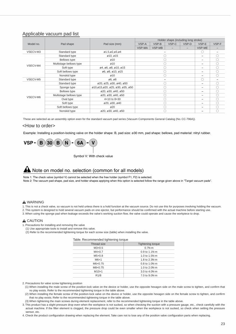
WARNING1. This is not a check valve, so vacuum is not held unless there is a hold function at the vacuum source. Do not use this for purposes involving holding the vacuum.2. This system is designed to hold several vacuum pads on one ejector, but performance should be confi rmed with the actual machine before starting use.3. When using the sponge pad when leakage exceeds the valve's working suction fl ow, the valve could operate and cause the workpiece to drop.
CAUTION1. Precautions for installing and removing the valve
(1) Use appropriate tools to install and remove this valve.(2) Refer to the recommended tightening torque for each screw size (table) when installing the valve.
Table. Recommended tightening torque Thread size Tightening torque M3×0.5 0.7N·m M4×0.7 0.9 to 1.1N·m M5×0.8 1.0 to 1.5N·m M6×1 1.8 to 2.3N·m M6×0.75 0.8 to 1.0N·m M8×0.75 1.0 to 2.0N·m M10×1 3.0 to 4.0N·m R1/8 7.0 to 9.0N·m
2. Precautions for valve screw tightening position(1) When installing the male screw of the position-lock valve on the device or holder, use the opposite hexagon side on the male screw to tighten, and confi rm that
no play exists. Refer to the recommended tightening torque in the table above.(2) When installing the female screw of the position-lock valve on the device or holder, use the opposite hexagon side on the female screw to tighten, and confi rm
that no play exists. Refer to the recommended tightening torque in the table above.(3) When tightening the main screws during element replacement, refer to the recommended tightening torque in the table above.
3. This product has a slight pressure drop even when the workpiece is not sucked, so when checking the suction with a pressure gauge, etc., check carefully with the actual machine. If the fi lter element is clogged, the pressure drop could be even smaller when the workpiece is not sucked, so check when setting the pressure sensor, etc.
4. Check the product confi guration drawing when replacing the element. Take care not to lose any of the position valve confi guration parts when replacing.
Applicable vacuum pad list
Model no.
VSECV-M3
VSECV-M4
VSECV-M5
VSECV-M6
Standard typeStandard typeBellows type
Multistage bellows typeSoft type
Soft bellows typeNonskid typeStandard typeStandard typeSponge typeBellows type
Multistage bellows typeOval typeSoft type
Soft bellows typeNonskid type
Pad shape
ø1.5,ø2,ø3,ø4ø10, ø15
ø10ø10
ø4, ø6, ø8, ø10, ø15ø6, ø8, ø10, ø15
ø10ø6, ø8
ø20, ø25, ø30, ø40, ø50ø10,ø15,ø20, ø25, ø30, ø35, ø50
ø20, ø30, ø40, ø50ø20, ø30, ø40, ø50
4×10 to 8×30ø20, ø30, ø40
ø20ø20, ø30, ø40, ø50
Pad size (mm)Holder shape (including long stroke)
VSP-AVSP-MA
VSP-BVSP-MB
VSP-C-
VSP-D-
VSP-EVSP-ME
VSP-F-
These are selected as an assembly option even for the standard vacuum pad series (Vacuum Components General Catalog (No. CC-796A)).
<How to order>
Symbol V: With check value
Example: Installing a position-locking valve on the holder shape: B, pad size: ø30 mm, pad shape: bellows, pad material: nitryl rubber.
VSP VB 30 B N 6A
Note on model no. selection (common for all models)Note 1: The check valve (symbol V) cannot be selected when the free holder (symbol F1, F2) is selected.Note 2: The vacuum pad shape, pad size, and holder shapes applying when this option is selected follow the range given above in "Target vacuum pads".

24
øP M2
H
M1
BL
A1
A2
M2
H
M1
A1
A2
LB
øP
For taper screw for tubeFor meter screw
Vacuum ejector side
Pad (workpiece) side
Vacuum ejector side
Pad (workpiece) side
VSECV
Model no.
VSECV-M3VSECV-M4VSECV-M5VSECV-M6VSECV-6A
M1
M3×0.5M4×0.7M5×0.8M6×1Rc1/8
M2
M3×0.5M4×0.7M5×0.8M6×1R1/8
A1
2.52.9348
A2
4.54.54.54.98
B
18.419.919.928.133.5
L
15.916.916.924.129.5
øP
810101214
Opposite sideH
810101214
0.71.61.64.04.8
0.090.090.090.090.1
Weight(g)
4.97.96.6
12.410.0
Effective sectional area (mm2)
Dimensions
255
1313
Minimum operational
suction rate of valve element( /min(ANR))
Controlled fl ow
Free fl ow

25
Example of piping
Vacuum pump
Vacuum switchover unit
Vacuum fi lterVacuum pad
Workpiece
Vacuum supply
Vacuum break
Compressor
Dry unit
Vacuum control (decompression)
Compact vacuum regulator
VSRVV Series
Ideal for controlling the base pressure of compact vacuum pumps
When installed between the vacuum valve and vacuum pad, the pressure of each pad is controlled.
A male screw (A) directly connected to the vacuum pump vacuum port is available.
The male screw (B) is directly installed on a pad diameter ø150, ø200 holder, and used to control pressure.
Features
Compact vacuum regulator
The base pressure and the terminal are controlled.

26
Specifi cations of pressure sensor with large digital display
Specifi cations
Power supply
Current consumption
Working pressure range
Withstanding pressure
Storage temperature range
Operating temperature range
Operating humidity range
Protective structure
Number of display
Responsiveness
Display accuracy
Temperature characteristics
Monitor
Pressure
display
Zero adjustment
Resolution
Pressure display element
Rated display range
Output no.
Output type
Switch capacity
Residual voltage
Pressure setting method
Switch Set pressure range
output Operating indication
Repeatability
Accuracy
Responsiveness
Setting hysteresis
Overload protection
-
12 to 24 VDC ±10% ripple P-P 10% or less
40mA or less
-100 to 100kPa
500kPa
-20 to 70˚C (atmospheric pressure and humidity 60%RH or less)
-10 to 50˚C (to be unfrozen.)
35 to 85%RH (to be unfrozen.)
IEC standards IP 40 or equivalent
4 time/second
Variable, approximate 5, 25, 250m sec depending on digital fi lter setting
±1 F.S.
±3%F.S. (0 to 50 ˚C, reference temperature: 25 ˚C)
Rated over
Detection range over
Output overload detection
Monitor of mis-adjustment
1 digit
21/2 digit and red LED character height: 11mm)
Refer to display range in below table
The unit setting is selected from the following units using panel operations:
2 point output (SW 1, SW 2)
NPN open collector
30 VDC 100mA or less
1.2V max. (load current: 100mA)
By panel switch operation
-110 to 110 digits. Decimal point follows display range given below
LED (SW 1, SW 2: red) lighting (output: ON)
±0.3F.S.
±0.5F.S. (0 to 50 ˚C and reference temperature: 25 ˚C)
Variable approximate 5, 25, 250m sec depending on digital fi lter setting
0 to 30 digits (variable by panel switch operation)
2 point output (SW 1, SW 2) OFF (approximate overload current: 200mA and over)
Blinking display (110% and over of rated pressure)
Negative pressure "-L-" and positive pressure "-H-" blinking display (A/D transform over)
"E1" blinking display/overload detection side output light blinking
Pressure display caused by panel SW operation/zero clear
Monitors zero adjustment when residual pressure exceeding ±0.06 Pr is
applied, and blinks air warning "E2." Released with panel switching.
Pressure range (rated display range)
-
-100 to 100
-
-75 to 75
-1.00 to 1.00
-14.5 to 14.5
Display magnifi cation (unit)
×1 (kPa)
×1 (MPa)
×0.75 (cmHg)
×0.01 (bar)
×0.145 (psi)
Specifi cations of regulator section
Pressure display Type without pressure display With ø30 vacuum gauge
Working fl uid Air
Working pressure range -100 to 100kPa -100 to 0kPa
Set pressure range -100 to -1.3kPa
Suction fl ow 30 /min(ANR)
Ambient temperature range 0 to 50˚C 0 to 40˚C
Pressure sensorwith large digital display
27
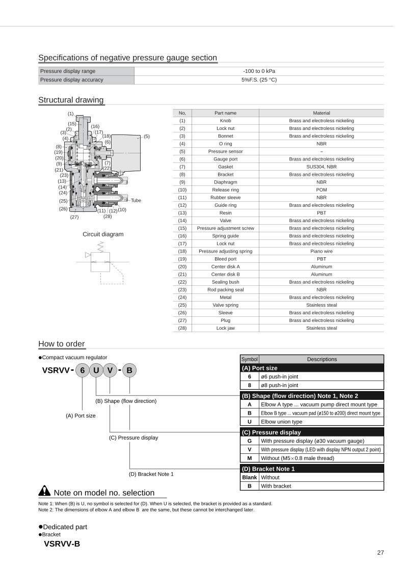
6
8
ø6 push-in joint
ø8 push-in joint
(A) Port size
(B) Shape (flow direction)
(C) Pressure display
(D) Bracket Note 1
(A) Port size
Symbol Descriptions
Note on model no. selection
VSRVV B6 U V
VSRVV-B
A
B
U
Elbow A type ... vacuum pump direct mount type
Elbow B type ... vacuum pad (ø150 to ø200) direct mount type
Elbow union type
(B) Shape (flow direction) Note 1, Note 2
G
V
M
With pressure display (ø30 vacuum gauge)
With pressure display (LED with display NPN output 2 point)
Without (M5 0.8 male thread)
(C) Pressure display
Blank
B
Without
With bracket
(D) Bracket Note 1
Note 1: When (B) is U, no symbol is selected for (D). When U is selected, the bracket is provided as a standard.Note 2: The dimensions of elbow A and elbow B are the same, but these cannot be interchanged later.
•Compact vacuum regulator
•Bracket•Dedicated part
How to order
Structural drawing
No,
(1)
(2)
(3)
(4)
(5)
(6)
(7)
(8)
(9)
(10)
(11)
(12)
(13)
(14)
(15)
(16)
(17)
(18)
(19)
(20)
(21)
(22)
(23)
(24)
(25)
(26)
(27)
(28)
Part name
Knob
Lock nut
Bonnet
O ring
Pressure sensor
Gauge port
Gasket
Bracket
Diaphragm
Release ring
Rubber sleeve
Guide ring
Resin
Valve
Pressure adjustment screw
Spring guide
Lock nut
Pressure adjusting spring
Bleed port
Center disk A
Center disk B
Sealing bush
Rod packing seal
Metal
Valve spring
Sleeve
Plug
Lock jaw
Material
Brass and electroless nickeling
Brass and electroless nickeling
Brass and electroless nickeling
NBR
-
Brass and electroless nickeling
SUS304, NBR
Brass and electroless nickeling
NBR
POM
NBR
Brass and electroless nickeling
PBT
Brass and electroless nickeling
Brass and electroless nickeling
Brass and electroless nickeling
Brass and electroless nickeling
Piano wire
PBT
Aluminum
Aluminum
Brass and electroless nickeling
NBR
Brass and electroless nickeling
Stainless steal
Brass and electroless nickeling
Brass and electroless nickeling
Stainless steal
Specifi cations of negative pressure gauge section
Pressure display range -100 to 0 kPa
Pressure display accuracy 5%F.S. (25 °C)
Circuit diagram
(1)
(15)(2)
(3)(4)
(8)(19)(20)(9)
(21)(23)
(13)(14)(24)
(25)
(26)
(27)(11)
(28)(12)(10)
Tube
(5)
(16)
(6)
(17)(18)
(7)(22)

28
ø122032
CE
2-ø6.5
19.4252
Hex. 12
Hex. 19
Hex. 10
Hex. 27
R1/4
ø22
7.7
534
230
.8 2311
12.5
øD
ø14
.4M
ax.7
8
Min
.70.
5
7.5
Relief port
Bleed port
BracketVSRVV-B
SET side
VAC side
M5 0.8Depth: 3.5
M16 1
WARNING1. When applying positive pressure to the regulator, do not use the ø30 pressure gauge. Use the pressure sensor with a large digital display when using positive
pressure. Application of excessive positive pressure could result in device damage.2. Before using, see the instruction manual for the vacuum source, and conduct suffi cient tests.
CAUTION1. Do not apply an excessive load or impact on the pressure gauge, pressure sensor, or gauge port. The device may be damaged or display accuracy may be
compromised.2. Use proper holding and fi xing when installing the product. When using a screw, use a wrench on the hexagon side (opposite : 27 mm) and tighten.
Installing on a different member could result in damage.3. When installing a gauge or pipe, etc., on the gauge port, use a wrench on the gauge port hexagon side (opposite : 10 mm) and tighten. When installing on an M5 ×
0.8 port, see the recommended tightening torque table and tighten. The device could be damaged or display accuracy be compromised because of leaks.
Table. Recommended tightening torque Thread size Tightening torque M5×0.8mm 1.0 to 1.5N·m
4. If dirt or particles could be sucked in, attach a vacuum fi lter to the vacuum regulator pressure adjustment side (workpiece side), or operation could fail if foreign matter is sucked in.
5. Do not plug the bleed port or relief port. Secondary pressure could become unstable.6. When applying positive pressure to the regulator, air will fl ow out of the bleed port. Check when using in a clean room, etc.7. When applying break air, take the amount of leakage from the bleed port into consideration when setting.8. Do not use the pressure gauge where pressure fl uctuation is high (high cycle).
VSRVV-*AM-*
Model no.
VSRVV-6AM-*VSRVV-8AM-*
Applicable tube outer diameter
øD
68
C
1718.1
E
2928.9
Weight(g)
127128
* Dimensions at left are for the type with bracket.
Dimensions

29
48.925
252
Hex. 12
Hex. 19
Hex. 10Hex. 27
R1/4
ø22
7.7
534
230
.8 2311
12.5 Relief port
Bleed port
ø1220
3231
CE
2-ø6.5
Digital sensor
øD
ø14
.4M
ax.7
8
Min
.70.
5
BracketVSRVV-B
SET side
VAC side
M16 1
40.416.5
252
Hex. 12
Hex. 19
Hex. 27
R1/4
ø22
7.7
534
230
.8 2311
12.5
Relief port
Bleed port
ø122032
CE
2-ø6.5
Vacuum gauge
øD
ø14
.4
ø30
Max
.78
Min
.70.
5
BracketVSRVV-B
SET side
VAC side
M16 1
VSRVV-*AV-*
Model no.
VSRVV-6AV-*VSRVV-8AV-*
Applicable tube outer diameter
øD
68
C
1718.1
E
2928.9
VSRVV-*AG-*
Model no.
VSRVV-6AG-*VSRVV-8AG-*
Applicable tube outer diameter
øD
68
C
1718.1
E
2928.9
Weight(g)
193193
Weight(g)
156156
* Dimensions at left are for the type with bracket.
* Dimensions at left are for the type with bracket.

30
ø122032
CE
2-ø6.5
19.4252
Hex. 12
Hex. 19
Hex. 10
Hex. 27
R1/4
ø22
7.7
534
230
.8 2311
12.5
øD
ø14
.4M
ax.7
8
Min
.70.
5
7.5
Relief port
Bleed port
BracketVSRVV-B
VAC side
SET side
M5 0.8Depth: 3.5
M16 1
48.925
252
Hex. 12
Hex. 19
Hex. 10Hex. 27
R1/4
ø22
7.7
534
230
.8 2311
12.5 Relief port
Bleed port
ø1220
3231
CE
2-ø6.5
Digital sensor
øD
ø14
.4M
ax.7
8
Min
.70.
5
BracketVSRVV-B
VAC side
SET side
M16 1
VSRVV-*BM-*
Model no.
VSRVV-6BM-*VSRVV-8BM-*
Applicable tube outer diameter
øD
68
C
1718.1
E
2928.9
VSRVV-*BV-*
Model no.
VSRVV-6BV-*VSRVV-8BV-*
Applicable tube outer diameter
øD
68
C
1718.1
E
2928.9
Weight(g)
127128
Weight(g)
193193
* Dimensions at left are for the type with bracket.
* Dimensions at left are for the type with bracket.

31
40.416.5
252
Hex. 12
Hex. 19
Hex. 27
R1/4
ø22
7.7
534
230
.8 2311
12.5
Relief port
Bleed port
ø122032
CE
2-ø6.5
Vacuum gauge
øD
ø14
.4
ø30
Max
.78
Min
.70.
5
BracketVSRVV-B
VAC side
SET side
M16 1
19.4252
Hex. 12
Hex. 19
Hex. 10
Hex. 27
ø23
7.7
57.3
42
30.8
1523
11
3.5
7.5
Relief port
Bleed port
ø122032
2-C2-E
2-ø6.5
Hex. 21
2-ø
D2-
ø14
.4Max
.81.
8
Min
.74.
3
BracketVSRVV-B
VAC side
SET side
M5 0.8Depth: 3.5
M16 1
VSRVV-*BG-*
Model no.
VSRVV-6BG-*VSRVV-8BG-*
Applicable tube outer diameter
øD
68
C
1718.1
E
2928.9
VSRVV-*UM
Model no.
VSRVV-6UMVSRVV-8UM
Applicable tube outer diameter
øD
68
C
1718.1
E
2928.9
Weight(g)
156156
Weight(g)
180181
* Dimensions at left are for the type with bracket.

32
48.925
252
Hex. 12
Hex. 19
Hex. 27
ø23
7.7
57.3
42
30.8
1523
11
3.5
Relief port
Bleed port
ø1220
32
2-C2-E
2-ø6.5
Hex. 21
Digital sensor
2-ø
D2-
ø14
.4Max
.81.
8
Min
.74.
3
BracketVSRVV-B
VAC side
SET side
31
M16 1
(40.4)16.5
252
Hex. 12
Hex. 19
Hex. 27
ø23
7.7
57.3
42
30.8
1523
11
3.5
Relief port
Bleed port
ø30
ø122032
2-C2-E
2-ø6.5
Hex. 21
Vacuum gauge
2-ø
D2-
ø14
.4Max
.81.
8
Min
.74.
3
BracketVSRVV-B
VAC side
SET side
M16 1
VSRVV-*UV
Model no.
VSRVV-6UVVSRVV-8UV
Applicable tube outer diameter
øD
68
C
1718.1
E
2928.9
VSRVV-*UG
Weight(g)
246247
Model no.
VSRVV-6UGVSRVV-8UG
Applicable tube outer diameter
øD
68
C
1718.1
E
2928.9
Weight(g)
209210

33
70
65
60
55
50
45
90 85 80 75 70 65Primary pressure (-kPa)
Sec
onda
rypr
essu
re(-
kPa)
A type
A type
A type
B, U type
B, U type
B, U type
80
70
60
50
40
30
20
10
0
5 10 15 20 25 30 35
Sec
onda
rypr
essu
re(-
kPa)
A type
A type
A type
B, U type
B, U type
B, U type
Flow ( /min. (ANR))
Pressure characteristics diagram
Flow characteristics diagram

34
MEMOMEMOMEMOMEMOMEMO

35
Vacuum system components
Related products
Catalog No.CC-796A
Compact designCompact and space savingWide series variationBroad series of models and variations enable use in different fields and applications.Modular designThe core vacuum ejector and vacuum unit is designed with unitization and modularization to save space and facilitate use.
Fiber tube UP Series Catalog No.CC-784
Extremely narrow tube with outer diameter ø1.8Stress greatly reduced after piping!
Vacuum ejector/vacuum unitThe vacuum ejector and vacuum unit function as the core of the vacuum system.Different types available include discrete to unit types combining different related components.
Vacuum padThis attachment directly picks up the workpiece.Different materials, shapes, and pad diameters match target workpiece size, weight, and characteristics.
Vacuum related productsDifferent components including vacuum break valves, vacuum sensors, and vacuum filters match vacuum system applications.
Related productsComponents suitable for creating an advanced vacuum system include vacuum filters, vacuum regulators, quick valves, precision suction plates, and buffers.
Vacuum ejector/vacuum unit
Vacuum pad
Vacuum related components
Related components

Specifications are subject to change without notice.
The goods and their replicas, or the technology and software in this catalog are subject to complementary export regulations by Foreign Exchange and Foreign Trade Law of Japan.If the goods and their replicas, or the technology and software in this catalog are to be exported, laws require the exporter to make sure they will never be used for the development or the manufacture of weapons for mass destruction.
2006.10.CHC