vacuum-assisted wet processing for … wet processing for advanced 3d devices jennifer rieker, gim...
TRANSCRIPT

VACUUM-ASSISTED WET PROCESSING FOR ADVANCED 3D DEVICES
Jennifer Rieker, Gim Chen and Ismail Kashkoush
Akrion Systems LLC 6330 Hedgewood Drive, Allentown, PA 18106, USA
Damien Michel and Patrick Daoust Teledyne-DALSA Semiconducteur
18 Boulevard de l’Aéroport, Bromont, QC J2L 1S8, Canada
Irina Stateikina C2MI
45 Boulevard de l'Aéroport, Bromont, QC J2L 1S8, Canada
ABSTRACT
The penetration of liquid into high aspect ratio (HAR) features presents a challenging situation in device fabrication where the removal of residue and/or oxide inside the structures is critical before processing through the subsequent steps. Conventional methods have proven inadequate for getting chemical to reach the bottom of such structures. This paper examines the use of a vacuum priming wet immersion method to introduce liquid chemicals or rinse water throughout the entire HAR feature prior to the oxide etching step. The data show that by pulling a vacuum below the saturated vapor pressure of water, liquid can be successfully drawn into the entire feature, enabling a uniform oxide etch. Conversely, without the initial vacuum priming step the etching will not be uniform and oxide will remain at the bottom of the trench or via. The results confirm the physical dynamics within such features as well as the need for a more in-depth study to fully understand the vacuum priming and drying mechanisms as they relate to different aspect ratios and geometries.
Key words: vacuum priming, vacuum drying, high aspect ratio, TSV, 3D INTRODUCTION The development of high aspect ratio structures (e.g. ≥30:1) introduces a new challenge to semiconductor and MEMS processing. For example, in three-dimensional (3D) integration, the use of through silicon vias (TSV) can result in aspect ratios as high as 110:1 [1]. With features approaching these depths, the ability of chemical to penetrate the entire structure becomes much more difficult, particularly when the wafers are hydrophobic, where the surface tension is high [2]. If the penetration of liquid chemicals is not complete within these types of structures, contaminants, residues and/or oxide films may be left behind, which can cause serious problems for the subsequent process steps.
Both semiconductor and MEMS processing require the uniform deposition of layers that must be in direct and
complete contact with one another [3]. Residues left over from the etch process and not completely cleaned in the next process step can interfere with the electrical inter-connections of the overall device [4-6]. Similarly, if an oxide (or other) layer has not been fully etched, it will prevent the continuous metal contact between the previous and subsequent layers. These situations can both severely affect the overall process yield.
Conventional etching/cleaning methods with aspect ratios <30:1 have long been proven to be successful. As the wafers are lowered into the process tank and liquid starts to cover the surface of the wafers, it will make its way into any open features on the wafer surface, i.e. vias and trenches. When the structures are shallow enough, the pressure exerted by the approaching liquid is greater than the opposing force of the trapped air below, which eventually dissolves into the liquid. As a result, the entire trench and/or via structure is filled with liquid for a uniform etch/clean via mass transfer mechanisms.
However, when aspect ratios start approaching 30:1 and beyond, the physical dynamics within the trenches/vias become too great to overcome. When the feature sizes get deeper, the amount of air within those structures also increases. As the liquid starts entering the structures, that air becomes compressed and builds up pressure. Eventually that pressure becomes greater than that of the approaching liquid and prevents it from penetrating any further [7], i.e. no mass transfer. One way to combat this problem is to first pull a vacuum before introducing any liquid. This helps to eliminate any trapped air, allowing the liquid to flow freely throughout the entire length of the trench/via.
The phenomenon of liquid infiltration has long been studied in the area of soil saturation, where many papers have been published on the topic [8-9]. However, its relation to and application in semiconductor, MEMS and 3D device processing is new. This paper outlines some insights into the mechanism and physical laws governing wafer priming and drying as well as how to achieve positive results for aspect ratios up to 50:1.
BACKGROUND
The difficulty with getting liquids to penetrate high aspect ratio features is a result of several factors: 1) the surface tension of the liquid, 2) pressure of the approaching liquid and 3) the gas pressure of the trapped air [10] (see Fig. 1). The surface tension of the liquid is a physical characteristic of the chemistry, of which any change would require the reformulation of standard chemicals that have long been in use in the industry (DHF, BOE, SC1). Furthermore, simply reducing the surface tension through the use of surfactants still would not allow the liquid to overcome the gas pressure of the trapped air below.
Figure 1: Example of trapped air below liquid level in a high aspect ratio feature As wafers are processed under atmospheric conditions, any open features such as vias or trenches will essentially be filled with air. As they are processed in liquid chemical etchants or cleaners, the liquid will infiltrate the vias/trenches until either: a) the trapped air is dissolved within the approaching liquid or b) the trapped air pressure becomes greater than the approaching liquid pressure. The latter case is what is found to occur in high aspect ratio features [10]. In order to overcome this phenomenon, the air within the system needs to be transferred out so that it doesn’t have the opportunity to become trapped beneath the liquid surface. This can be accomplished by pulling a vacuum before introducing liquid into the processing chamber. However, the ability of liquid to entirely fill the high aspect ratio structures is still dependent upon the saturated vapor pressure (SVP) of the liquid. In other words, a vacuum must be pulled to a level below the SVP of the liquid in order for priming to be complete. The saturated vapor pressure of water occurs when the vapor phase is in thermodynamic equilibrium with the liquid. As the temperature increases, the pressure rises significantly since more molecules are able to escape the surface of the liquid (see Fig 2).
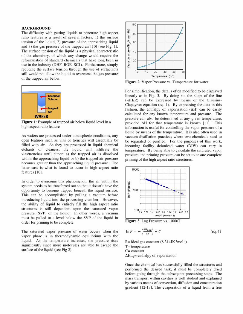
Figure 2: Vapor Pressure vs. Temperature for water For simplification, the data is often modified to be displayed linearly as in Fig. 3. By doing so, the slope of the line (-∆H/R) can be expressed by means of the Clausius-Clapeyron equation (eq. 1). By expressing the data in this fashion, the enthalpy of vaporization (∆H) can be easily calculated for any known temperature and pressure. The pressure can also be determined at any given temperature, provided ∆H for that temperature is known [11]. This information is useful for controlling the vapor pressure of a liquid by means of the temperature. It is also often used in vacuum distillation practices where two chemicals need to be separated or purified. For the purposes of this work, incoming facility deionized water (DIW) can vary in temperature. By being able to calculate the saturated vapor pressure, the priming pressure can be set to ensure complete priming of the high aspect ratio structures.
Figure 3: Log Pressure vs. 1000/T
ln � = −�∆�� � � + � (eq. 1)
R= ideal gas constant (8.314JK-1mol-1) T= temperature C= constant ∆Hvap= enthalpy of vaporization
Once the chemical has successfully filled the structures and performed the desired task, it must be completely dried before going through the subsequent processing steps. The mass transport within cavities is well studied and explained by various means of convection, diffusion and concentration gradient [12-13]. The evaporation of a liquid from a free
surface is given by Langmuir’s equation, shown in eq. 2, which gives the rate of mass loss M per unit time t. Based on this calculation, if Pv is greater than Pp, evaporation occurs and if Pp is greater than Pv, condensation will occur. However, the evaporation of liquid from high aspect ratio features is more difficult due to the fact that water vapor must escape from restricted areas, as opposed to a free surface. ���� = � ∗ (�� − ��)��/2� ! (eq. 2)
Pv= vapor pressure of liquid Pp= partial pressure of vapor m= mass k= Boltzmann constant (1.3806x10⁻²³JK-1) T= temperature α= constant These restricted, high aspect ratio features could present a situation where drying is much more difficult. For instance, as the water evaporates, the molecules can create waves inside the trenches. Under the right circumstances, a standing wave may develop, which will impede the evaporation. However, this phenomenon goes beyond the scope of this paper and has not been addressed as part of the current work.
EXPERIMENTAL
Vacuum Priming/Drying Modules
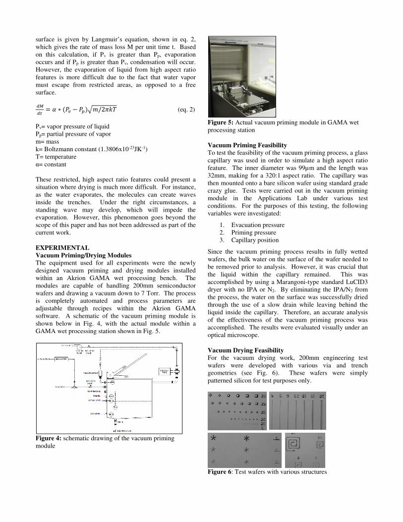
The equipment used for all experiments were the newly designed vacuum priming and drying modules installed within an Akrion GAMA wet processing bench. The modules are capable of handling 200mm semiconductor wafers and drawing a vacuum down to 7 Torr. The process is completely automated and process parameters are adjustable through recipes within the Akrion GAMA software. A schematic of the vacuum priming module is shown below in Fig. 4, with the actual module within a GAMA wet processing station shown in Fig. 5.
Figure 4: schematic drawing of the vacuum priming module
Figure 5: Actual vacuum priming module in GAMA wet processing station
Vacuum Priming Feasibility
To test the feasibility of the vacuum priming process, a glass capillary was used in order to simulate a high aspect ratio feature. The inner diameter was 99µm and the length was 32mm, making for a 320:1 aspect ratio. The capillary was then mounted onto a bare silicon wafer using standard grade crazy glue. Tests were carried out in the vacuum priming module in the Applications Lab under various test conditions. For the purposes of this testing, the following variables were investigated:
1. Evacuation pressure 2. Priming pressure 3. Capillary position
Since the vacuum priming process results in fully wetted wafers, the bulk water on the surface of the wafer needed to be removed prior to analysis. However, it was crucial that the liquid within the capillary remained. This was accomplished by using a Marangoni-type standard LuCID3 dryer with no IPA or N2. By eliminating the IPA/N2 from the process, the water on the surface was successfully dried through the use of a slow drain while leaving behind the liquid inside the capillary. Therefore, an accurate analysis of the effectiveness of the vacuum priming process was accomplished. The results were evaluated visually under an optical microscope. Vacuum Drying Feasibility
For the vacuum drying work, 200mm engineering test wafers were developed with various via and trench geometries (see Fig. 6). These wafers were simply patterned silicon for test purposes only.
Figure 6: Test wafers with various structures
To determine the completeness of the vacuum drying process, the wafers were weighed before processing (control), after vacuum priming and again after vacuum drying. The wafers were also subject to a 5 hour dry under vacuum to make sure all moisture was removed prior to beginning the tests. A microbalance capable of measuring to 4 decimal places was used for the experiments. The following process flow was utilized for all tests:
Figure 7: Process flow for vacuum drying feasibility testing
Vacuum Priming Field Testing
Two types of wafers were used to test the vacuum priming process on structures more closely resembling those found in MEMS and/or 3D IC manufacturing. The first type consisted of engineering test wafers with trenches of different aspect ratios, up to 50:1. These were similar to those used for the vacuum drying feasibility experiments except that these wafers contained 1000Å of thermally grown oxide on the sidewalls. The second wafer type was a special design that, despite being shallow at only 1.5:1, was known to have difficulty with complete chemical contact to the bottom of the structures. The design, shown below in Fig. 8, has oxide only on the very bottom of the features.
Figure 8: Special design wafer for vacuum priming Both wafer types were run with and without the vacuum priming step, to be able to determine the comparison in performance. The standard process flow for the experiments is shown below in Fig. 9. For the purpose of these experiments, the best known method (BKM), that includes concentration, temperature, pressure, and process time, was used for both the vacuum priming and vacuum drying steps.
Figure 9: Process flow for etching experiments with vacuum priming/drying
RESULTS AND DISCUSSION
Vacuum Priming Feasibility
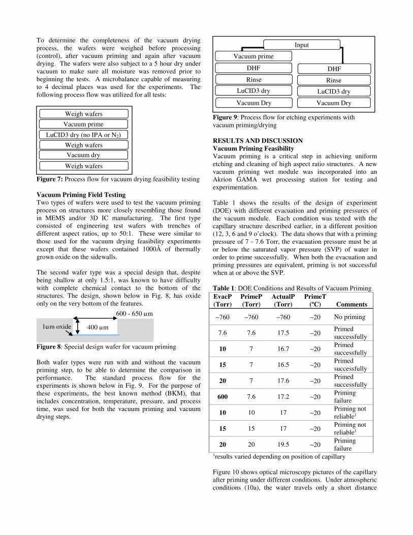
Vacuum priming is a critical step in achieving uniform etching and cleaning of high aspect ratio structures. A new vacuum priming wet module was incorporated into an Akrion GAMA wet processing station for testing and experimentation. Table 1 shows the results of the design of experiment (DOE) with different evacuation and priming pressures of the vacuum module. Each condition was tested with the capillary structure described earlier, in a different position (12, 3, 6 and 9 o’clock). The data shows that with a priming pressure of 7 - 7.6 Torr, the evacuation pressure must be at or below the saturated vapor pressure (SVP) of water in order to prime successfully. When both the evacuation and priming pressures are equivalent, priming is not successful when at or above the SVP. Table 1: DOE Conditions and Results of Vacuum Priming EvacP
(Torr)
PrimeP
(Torr)
ActualP
(Torr)
PrimeT
(ºC) Comments
∼760 ∼760 ∼760 ∼20 No priming
7.6 7.6 17.5 ∼20 Primed successfully
10 7 16.7 ∼20 Primed successfully
15 7 16.5 ∼20 Primed successfully
20 7 17.6 ∼20 Primed successfully
600 7.6 17.2 ∼20 Priming failure
10 10 17 ∼20 Priming not reliable1
15 15 17 ∼20 Priming not reliable1
20 20 19.5 ∼20 Priming failure
1results varied depending on position of capillary Figure 10 shows optical microscopy pictures of the capillary after priming under different conditions. Under atmospheric conditions (10a), the water travels only a short distance
Weigh wafers
Vacuum prime
LuCID3 dry (no IPA or N2)
Weigh wafers
Vacuum dry
Weigh wafers
400 µm
600 - 650 µm
DHF
Rinse
LuCID3 dry
Vacuum Dry
Input
Vacuum prime
DHF
Rinse
LuCID3 dry
Vacuum Dry
1µm oxide

inside the capillary. When close to the saturated vapor pressure of water, an air bubble is still present at the bottom (10b). When well below the SVP, the entire capillary has been filled with water (10c).
Figure 10: Optical pictures of capillary at (a) atmospheric, (b) 20/20 Torr and (c) 7.6/7.6 Torr The effect of temperature on pressure in a real world scenario can be seen in Fig 11 below. Wafers were loaded into the vacuum chamber, which was then evacuated to a set point pressure of 7.6 Torr. After reaching the set point, the priming liquid was introduced into the chamber. Once this occurred, both the temperature and pressure increased, as can be clearly seen in the graph. The temperature jumped to 21ºC while the pressure increased to 18.7 Torr. As discussed previously, the vapor pressure is temperature dependent and reaches equilibrium when the number of molecules leaving the surface is equivalent to those returning, i.e. condensing. At that point, the vapor is saturated and the corresponding pressure is the saturated vapor pressure (SVP). Even if a lower pressure is being requested through the software, it cannot physically go below the SVP. As a result, the pressure of 18.7 Torr shown in Fig. 11 is the SVP for a temperature of 21ºC, as shown previously in Fig. 2.
Figure 11: Typical vacuum priming process
Vacuum Drying Feasibility The effectiveness of the vacuum drying process was studied through a change in weight after vacuum priming and again after vacuum drying. The results in Fig. 12 below show an increase in overall weight after the vacuum priming process. This indicates that the vacuum priming was successful in pulling liquid into the features. After the subsequent vacuum drying process, the weight returns to the original values before any processing had occurred.
Figure 12: Weight Measurements after Vacuum Priming and Drying
The typical process flow for the vacuum drying chamber is shown below in Fig. 13. It is similar to the priming step described previously except that no fluid is introduced into the system. This is the last step in the wet processing sequence.
Figure 13: Typical vacuum drying process Vacuum Priming Field Testing
The previous capillary tests successfully demonstrated the concept of being able to use a vacuum priming process for high aspect ratio structures prior to traditional wet processing. However, additional testing was needed on actual test wafers in order to thoroughly prove the concept. The results after DHF etching of a 50:1 aspect ratio (0.50µm opening) trench with and without a vacuum priming step are shown below in Fig. 14. Without any vacuum priming step, oxide was still present at the bottom of the trench after the etch. In contrast, when a vacuum priming step was applied first, etching was complete throughout the entire feature.
out ofbox
after5hr
vacuum
aftervacuumprime
aftervacuum
dryWafer 11 52.1157 52.1159 52.2628 52.1155
Wafer 12 52.1047 52.1044 52.2247 52.1051
52.0052.0552.1052.1552.2052.2552.30
Wei
ght (
gram
s)
(
trapped
air trapped
air
water fully
filled
with
water
(a) (b) (c)
Figure 14: SEM pictures of trenches with and without vacuum priming
A second test structure was also used for experimentation. Despite being very wide and shallow, conventional wet processing methods were not capable of etching the oxide on the bottom of these structures. Using an optical microscope to examine the bottom surface conditions, the changes in color (Fig. 15) visible after the vacuum priming process indicated that etching had occurred. This was confirmed by the SEM pictures shown in Fig. 15. One possible cause for the difficulty of wetting these shallow structures is that the walls are more hydrophobic (silicon) and may have very thin residues of Bosch polymers on the scallops.
Figure 15: Optical microscopy pictures with and without vacuum priming
Figure 16: SEM pictures with and without vacuum priming
CONCLUSIONS Experiments were conducted on new vacuum priming and drying modules with MEMS 3D devices. For vacuum priming, feasibility test data showed that for a priming pressure of 7.6 Torr, the chamber must be evacuated to a level at or near the saturated vapor pressure of water in order to be successful. It was also shown that having equivalent evacuation and priming pressures was unreliable, even when below the SVP. It was only successful when both pressures were maintained at the lowest level of 7.6 Torr.
Using the BKM of 7.6 Torr, data on both the trench structures (50:1) and the special design features, a uniform etch was observed in the case of vacuum priming prior to etching in DHF. Without this step, oxide remained at the bottom of both structures. More work is required to characterize the results on the oxide filled trenches. Further research will investigate the benefits of the priming technology on other types of features, such as arrays of deep vias and the cleaning performance of SC1 on complex MEMS.
Experiments were also conducted on the vacuum drying module to ensure that all the liquid can be successfully removed at the end of a process. The testing was conducted using the current BKM for the vacuum dryer (7.6 Torr) and showed that the liquid was successfully removed, as designated by a return of the weight to the original control value.
REFERENCES
[1] Fischer, A.C, et. al. (2011). Fabrication of High Aspect Ratio Through Silicon Vias (TSVs) by Magnetic Assembly of Nickel Wires. Proceedings from IEEE 24th International Conference on MEMS, pp. 37-40.
[2] Ota, K. & Tsutsumi, A. (2007). Liquid Infiltration Mechanism for Cleaning in Deep Microholes. ECS
Transactions, vol. 11 no. 2, pp. 299-306. [3] Hughes-Oliver, J., et. al. (1998). Achieving Uniformity
in a Semiconductor Fabrication Process Using Spatial Modeling. Journal of the American Statistical
Association, vol. 93, no. 441, pp. 36-45. [4] Spicer, R. (2011). Wafer Cleaning: The Next Frontier
in Semiconductor Fabrication. Solid State Technology, vol. 54, no. 2, pp. 19.
[5] Butterbaugh, J., et. al. (2000). Yield Enhancement by Cryokinetic Cleaning. Electrochemical Society Proceedings, vol. 99-36, pp. 335-342.
[6] Park, J., et. al. (2008). A Study of Single-Wafer Process in Metal Contact Hole Cleaning. Solid State
Phenomena, vol. 134, pp. 177-180. [7] Irimia, D. (2008). Capillary Force Valves.
Encyclopedia of Microfluidics and Nanofluidics, vol. 33, pp. 192-196.
[8] Novak, V. (2000). Infiltration of Water into Soil with Cracks. Journal of Irrigation and Drainage
Engineering, vol. 126, issue 1, pp. 41-47.
Without vacuum
prime, no color/varia
tion indicates
no etching
With vacuum prime, color
variation indicates
etching has occurred
Without vacuum prime With vacuum prime
Oxide remains
Oxide removed
oxide remains
oxide completely
removed
Without vacuum prime
With vacuum prime
[9] Zhan, T., et. al. (2004). Analytical Analysis of Rainfall Infiltration Mechanism in Unsaturated Soils. International Journal of Geomechanics, vol. 4, issue 4, pp. 273-284.
[10] Ota, K. and Tsutsumi. (2007). Liquid Infiltration Mechanism for Cleaning in Deep Microholes, ECS
Transactions, vol. 11, no. 2, pp. 299-306. [11] Lowe, J. (1990). Variation of Vapor Pressure with
Temperature, Penn State University. [12] Wiley, J. (2008). Fundamentals of Mass, Momentum
and Heat Transfer, 5th Edition, Ch. 24 and Ch. 26. [13] Wiley, J and Dewitt, D. (2006). Fundamentals of Heat
and Mass Transfer.