vacon - inverter drive, electrical motor distributor...
TRANSCRIPT

user manualethernet/ip
ac drivesvacon® 100 x
vacon® 100 flowvacon® 100 industrial


vacon • 1
table of contents
Document: DPD01045DVersion release date: 24.8.2016
1. Safety ...............................................................................................................31.1 Danger................................................................................................................................31.2 Warnings ............................................................................................................................41.3 Earthing and earth fault protection ...................................................................................52. EtherNet/IP - General info ...............................................................................62.1 Connections and Wiring .....................................................................................................62.1.1 ACD (Address Conflict Detection) ......................................................................................72.1.2 Technical details ................................................................................................................73. Ethernet installation ........................................................................................83.1 Installation in VACON® 100 INDUSTRIAL and FLOW .......................................................83.2 Prepare for use through Ethernet .....................................................................................93.3 Installation in VACON® 100 x ..........................................................................................114. Commissioning ..............................................................................................134.1 EtherNet common settings..............................................................................................134.1.1 IP Address mode ..............................................................................................................134.1.2 Fixed IP address, subnet mask and default gateway......................................................144.1.3 Active IP address, subnet mask and default gateway.....................................................144.1.4 MAC Address....................................................................................................................144.2 EtherNet/IP parameters ..................................................................................................144.2.1 Protocol in use .................................................................................................................154.2.2 Output Instance ................................................................................................................154.2.3 Input Instance...................................................................................................................154.2.4 Communication timeout ..................................................................................................154.3 EtherNet/IP monitoring menu .........................................................................................155. EtherNet/IP connection example ...................................................................176. EtherNet/IP....................................................................................................186.1 Overview ...........................................................................................................................186.2 AC/DC Drive Profile..........................................................................................................186.3 EDS file .............................................................................................................................186.4 Explicit Messaging ...........................................................................................................196.4.1 List of data types ..............................................................................................................196.4.2 General CIP error codes ..................................................................................................206.4.3 Connection Manager Object Error codes ........................................................................216.4.4 Supported CIP and Vendor Objects..................................................................................226.4.5 EtherNet/IP communication and connection timeout.....................................................237. Common Industrial Objects implemented by vacon® 100 family ...................257.1 CIP Common Required Objects .......................................................................................257.1.1 Identity Object, Class 0x01 ...............................................................................................257.1.2 Message Router Object, Class 0x02 ................................................................................287.1.3 Connection Manager Object, Class 0x06 .........................................................................287.1.4 TCP/IP Interface Object, Class 0xF5................................................................................307.1.5 Ethernet Link Object, Class 0xF6.....................................................................................367.2 Objects Present in an AC/DC Drive..................................................................................417.2.1 Assembly Object, Class 0x04 ...........................................................................................417.2.2 Motor Data Object, Class 0x28.........................................................................................417.2.3 Control Supervisor Object, Class 0x29 ............................................................................437.2.4 AC/DC Drive Object, Class 0x2A.......................................................................................487.3 Vendor Specific Objects ...................................................................................................527.3.1 Vendor Parameters Object, Class 0xA0...........................................................................52
24-hour support +358 (0)201 212 575 • Email: [email protected]

vacon • 2
7.3.2 Assembly Instance Selector Object, Class 0xBE.............................................................547.3.3 Motor Control Mode Object, Class 0xA1 ..........................................................................567.3.4 Fault History Object, class 0xA2 ......................................................................................588. Assembly instances implemented by vacon® 100 family...............................618.1 ODVA I/O Assembly instances for AC/DC Drive...............................................................618.1.1 ODVA Output Instances ....................................................................................................638.1.2 ODVA Input instances.......................................................................................................648.2 Vendor-specific I/O Assembly Instances .........................................................................668.2.1 Vendor Output Instances..................................................................................................668.2.2 Vendor Input Instances ....................................................................................................698.3 Mapping of Standard Output Assemblies onto VACON® data........................................728.3.1 FBGeneralControlWord and FBGeneralStatusWord.......................................................728.3.2 FBFixedControlWord........................................................................................................728.3.3 Start/Stop bit in VACON® FBFixedControlWord.............................................................728.3.4 Direction bit in VACON® FBFixedControlWord...............................................................738.3.5 Fault Reset bit in VACON® FBFixedControlWord...........................................................738.3.6 Request Fieldbus Control bit in VACON® FBFixedControlWord....................................738.3.7 Request Fieldbus Reference bit in VACON® FBFixedControlWord ...............................738.4 Mapping of VACON® data onto Standard Input Assemblies ..........................................738.4.1 FBFixedStatusWord .........................................................................................................738.4.2 Ready Indication bit in VACON® FBFixedStatusWord ....................................................738.4.3 Run/Stop Indication bit in VACON® FBFixedStatusWord ...............................................738.4.4 Direction Indication bit in VACON® FBFixedStatusWord ...............................................748.4.5 Fault Indication bit in VACON® FBFixedStatusWord......................................................748.4.6 Alarm Indication bit in VACON® FBFixedStatusWord ....................................................748.4.7 Setpoint Reached Indication bit in VACON® FBFixedStatusWord..................................748.4.8 Fieldbus Control indication in Input Assemblies.............................................................748.4.9 Fieldbus Reference indication in Input Assemblies........................................................748.4.10 FBSpeedReference in percentage...................................................................................749. APPENDIX 1 - VENDOR CONTROL AND STATUS WORD DESCRIPTIONS .........759.1 FBFixedControlWord and FBGeneralControlWord .........................................................759.2 FBFixedStatusWord and FBGeneralStatusWord.............................................................7610. APPENDIX 2 - FIELDBUS PARAMETRISATION................................................7710.1 Fieldbus control and basic reference selection ..............................................................7710.2 Torque control parametrization ......................................................................................7711. APPENDIX 3 - LWIP LICENCE .........................................................................78
Tel. +358 (0) 201 2121 • Fax +358 (0)201 212 205

Safety vacon • 3
1. SAFETY
This manual contains clearly marked cautions and warnings which are intended for your personal safety and to avoid any unintentional damage to the product or connected appliances.
Read the information included in cautions and warnings carefully.
The cautions and warnings are marked as follows:
1.1 Danger
Table 1. Warning signs
= DANGER! Dangerous voltage
= WARNING or CAUTION
= Caution! Hot surface
The components of the power unit are live when the drive is connected to mains potential. Coming into contact with this voltage is extremely dangerous and may cause death or severe injury.
The motor terminals U, V, W and the brake resistor terminals are live when the AC drive is connected to mains, even if the motor is not running.
After disconnecting the AC drive from the mains, wait until the indicators on the keypad go out (if no keypad is attached see the indicators on the cover). Wait 5 more minutes before doing any work on the connections of the drive. Do not open the cover before this time has expired. After expiration of this time, use a mea-suring equipment to absolutely ensure that no voltage is present. Always ensure absence of voltage before starting any electrical work!
The control I/O-terminals are isolated from the mains potential. However, the relay outputs and other I/O-terminals may have a dangerous control voltage present even when the AC drive is disconnected from mains.
Before connecting the AC drive to mains make sure that the front and cable cov-ers of the drive are closed.
During a ramp stop (see the Application Manual), the motor is still generating voltage to the drive. Therefore, do not touch the components of the AC drive before the motor has completely stopped. Wait until the indicators on the keypad go out (if no keypad is attached see the indicators on the cover). Wait additional 5 minutes before starting any work on the drive.
9000.emf
13006.emf
9001.emf
9000.emf
9000.emf
9000.emf
9000.emf
9000.emf
9000.emf
24-hour support +358 (0)201 212 575 • Email: [email protected]

1
vacon • 4 Safety
1.2 Warnings
The AC drive is meant for fixed installations only.
Do not perform any measurements when the AC drive is connected to the mains.
The earth leakage current of the AC drives exceeds 3.5mA AC. According to stan-dard EN61800-5-1, a reinforced protective ground connection must be ensured. See chapter 1.3.
If the AC drive is used as a part of a machine, the machine manufacturer is responsible for providing the machine with a supply disconnecting device (EN 60204-1).
Only spare parts delivered by VACON® can be used.
At power-up, power break or fault reset the motor will start immediately if the start signal is active, unless the pulse control for Start/Stop logic has been selected.Futhermore, the I/O functionalities (including start inputs) may change if param-eters, applications or software are changed. Disconnect, therefore, the motor if an unexpected start can cause danger.
The motor starts automatically after automatic fault reset if the auto restart function is activated. See the Application Manual for more detailed information.
Prior to measurements on the motor or the motor cable, disconnect the motor cable from the AC drive.
Do not touch the components on the circuit boards. Static voltage discharge may damage the components.
Check that the EMC level of the AC drive corresponds to the requirements of your supply network.
13006.emf
13006.emf
13006.emf
13006.emf
13006.emf
13006.emf
13006.emf
13006.emf
13006.emf
13006.emf
Tel. +358 (0) 201 2121 • Fax +358 (0)201 212 205

Safety vacon • 5
1.3 Earthing and earth fault protection
The AC drive must always be earthed with an earthing conductor connected to the earthing terminal marked with .
The earth leakage current of the drive exceeds 3.5mA AC. According to EN61800-5-1, one or more of the following conditions for the associated protective circuit shall be satisfied:
b) The protective conductor shall have a cross-sectional area of at least 10 mm2 Cu or 16 mm2 Al, through its total run.
c) Where the protective conductor has a cross-sectional area of less than 10 mm2 Cu or 16 mm2 Al, a second protective conductor of at least the same cross-sectional area shall be provided up to a point where the protective conductor has a cross-sectional area not less than 10 mm2 Cu or 16 mm2 Al.
d) Automatic disconnection of the supply in case of loss of continuity of the protective conduc-tor.
The cross-sectional area of every protective earthing conductor which does not form part of the supply cable or cable enclosure shall, in any case, be not less than:
- 2.5mm2 if mechanical protection is provided or- 4mm2 if mechanical protection is not provided.
The earth fault protection inside the AC drive protects only the drive itself against earth faults in the motor or the motor cable. It is not intended for personal safety.
Due to the high capacitive currents present in the AC drive, fault current protective switches may not function properly.
CAUTION!
Do not perform any voltage withstand tests on any part of the AC drive. There is a certain procedure according to which the tests shall be performed. Ignoring this procedure may result in damaged product.
NOTE! You can download the English and French product manuals with applicable safety, warning and caution information fromhttp://drives.danfoss.com/knowledge-center/technical-documentation/.
REMARQUE Vous pouvez télécharger les versions anglaise et française des manuels produit contenant l’ensemble des informations de sécurité, avertissements et mises en garde applicables sur le site http://drives.danfoss.com/knowledge-center/technical-documentation/.
13006.emf
13006.emf
24-hour support +358 (0)201 212 575 • Email: [email protected]
EtherNet/IP - General info vacon • 6
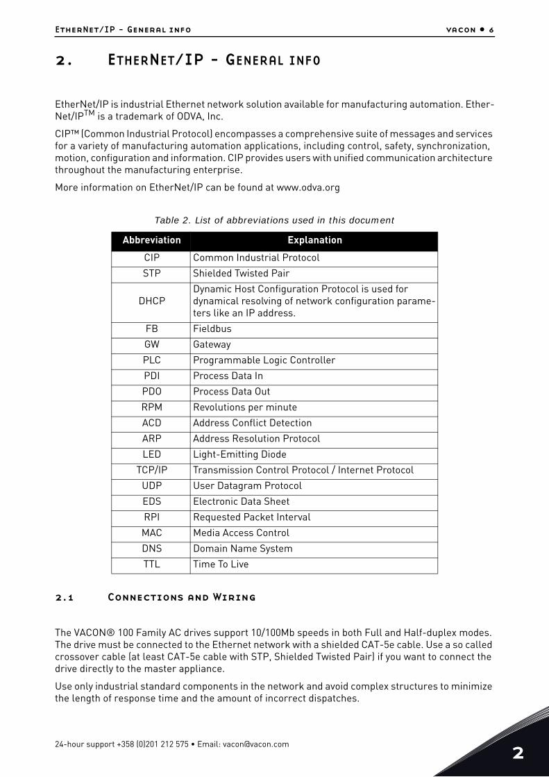
2. ETHERNET/IP - GENERAL INFO
EtherNet/IP is industrial Ethernet network solution available for manufacturing automation. Ether-Net/IPTM is a trademark of ODVA, Inc.
CIP™ (Common Industrial Protocol) encompasses a comprehensive suite of messages and services for a variety of manufacturing automation applications, including control, safety, synchronization, motion, configuration and information. CIP provides users with unified communication architecture throughout the manufacturing enterprise.
More information on EtherNet/IP can be found at www.odva.org
2.1 Connections and Wiring
The VACON® 100 Family AC drives support 10/100Mb speeds in both Full and Half-duplex modes. The drive must be connected to the Ethernet network with a shielded CAT-5e cable. Use a so called crossover cable (at least CAT-5e cable with STP, Shielded Twisted Pair) if you want to connect the drive directly to the master appliance.
Use only industrial standard components in the network and avoid complex structures to minimize the length of response time and the amount of incorrect dispatches.
Table 2. List of abbreviations used in this document
Abbreviation Explanation
CIP Common Industrial Protocol
STP Shielded Twisted Pair
DHCPDynamic Host Configuration Protocol is used for dynamical resolving of network configuration parame-ters like an IP address.
FB Fieldbus
GW Gateway
PLC Programmable Logic Controller
PDI Process Data In
PDO Process Data Out
RPM Revolutions per minute
ACD Address Conflict Detection
ARP Address Resolution Protocol
LED Light-Emitting Diode
TCP/IP Transmission Control Protocol / Internet Protocol
UDP User Datagram Protocol
EDS Electronic Data Sheet
RPI Requested Packet Interval
MAC Media Access Control
DNS Domain Name System
TTL Time To Live
24-hour support +358 (0)201 212 575 • Email: [email protected]

2
vacon • 7 EtherNet/IP - General info
2.1.1 ACD (Address Conflict Detection)
The VACON® 100 Family AC drives implement ACD algorithm (IETF RFC 5227). The implementation includes requirements from the EtherNet/IP protocol.
The ACD algorithm tries to actively detect if the IP address configured to this device is been used by another device in the same network. To accomplish this, ACD sends four ARP request packets when the device's Ethernet interface goes up or when its IP address changes. ACD prevents the use of the Ethernet interface until the ARP probing finishes. This delays the startup of fieldbus protocols about one second. During the delay or after it, the ACD passively checks incoming ARP messages for use of the device's IP address. If another device with the same IP address is detected, the ACD will try to defend its IP address with a single ARP message. If the other device with the same IP address also supports ACD, it should stop using the address. If not, the ACD will close the Ethernet connec-tion and indicate the situation with an alarm. This is done according the "DefendWithPolicyB". You cannot acknowledg the alarm if the problem is active. The ACD opens Ethernet connection if the other device with the same IP address disappears from the network. You can acknowledge the alarm after this.
Other policies are not supported. If the fieldbus protocol has been active, a fieldbus fault may be activated (depends on the fieldbus and drive application configuration).
2.1.2 Technical details
EtherNet/IP is a connection-oriented communication protocol designed for use in industrial envi-ronments. The protocol allows simple and complex industrial devices to communicate with each other.
Standard Ethernet and TCP/IP technology is used by the EtherNet/IP protocol. There are different messaging forms in EtherNet/IP:
• Connections are established using so-called "Unconnected Messaging”,• Real-time I/O data transfer happens through "Connected Messaging”
There are two kinds of connections in EtherNet/IP:
• General-purpose, point-to-point connections are known as "Explicit Messaging Connec-tions". These messages are sent using the TCP protocol.
• Connections for moving application-specific I/O data at regular intervals are known as "Implicit Connections" or "I/O Data Connections". These messages are sent using the UDP protocol
Tel. +358 (0) 201 2121 • Fax +358 (0)201 212 205

Ethernet installation vacon • 8
3. ETHERNET INSTALLATION
3.1 Installation in VACON® 100 INDUSTRIAL and FLOW
Figure 1.
1 Open the cover of the AC drive.
The relay outputs and other I/O-terminals may have a dangerous control voltage present even when the AC drive is disconnected from mains.
2 Locate the components that you will need on the AC drive to connect and run the Ethernet cables.
Be sure not to plug the Ethernet cable to the terminal under the keypad! This might harm your personal computer.
M4x55
9174.emf
13006.emf
24-hour support +358 (0)201 212 575 • Email: [email protected]

3
vacon • 9 Ethernet installation
3.2 Prepare for use through Ethernet
Figure 2.
3 Connect the Ethernet cable to its terminal and run the cable through the conduit as shown in Figure 2.
4
Protection class IP21: Cut free the opening on the AC drive cover for the Ether-net cable.Protection class IP54: Cut the rubber grommets open to slide the cables through. Should the grommets fold in while inserting the cable, just draw the cable back a bit to straighten the grommets up. Do not cut the grommet open-ings wider than what is necessary for the cables you are using.IMPORTANT: To meet the requirements of the enclosure class IP54, the connec-tion between the grommet and the cable must be tight. Therefore, lead the first bit of the cable out of the grommet straight before letting it bend. If this is not possible, the tightness of the connection must be ensured with insulation tape or a cable tie.
Ethernetcable
9316.emf
Tel. +358 (0) 201 2121 • Fax +358 (0)201 212 205
Ethernet installation vacon • 10
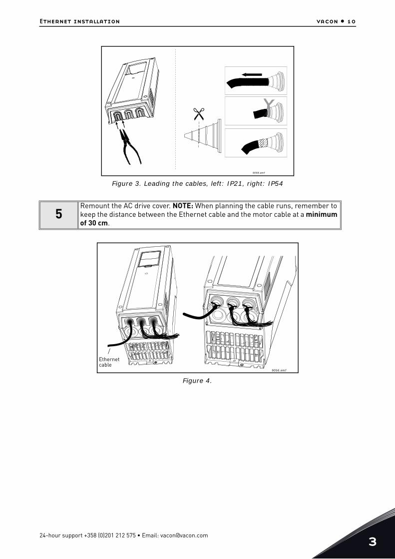
Figure 3. Leading the cables, left: IP21, right: IP54
Figure 4.
5Remount the AC drive cover. NOTE: When planning the cable runs, remember to keep the distance between the Ethernet cable and the motor cable at a minimum of 30 cm.
9068.emf
9056.emf
Ethernetcable
24-hour support +358 (0)201 212 575 • Email: [email protected]

3
vacon • 11 Ethernet installation
3.3 Installation in VACON® 100 x
1
Open the cover of the AC drive.
2
Remove the cable entry plate.
NOTE! The cable entry plate at the bottom of the drive is used only for mains and motor cables.
3 Open the necessary holes in the cable entry plate. Do not open the other holes. See the VACON ® 100X Installation Manual for the dimensions of the holes.
11638_00
11641_00
Tel. +358 (0) 201 2121 • Fax +358 (0)201 212 205

Ethernet installation vacon • 12
4
Attach a cable gland on the hole in the cable entry plate. Pull the EtherNet cable through the hole.
5 Put the cable entry plate back.
6 Close the cover of the AC drive.
11739_00
24-hour support +358 (0)201 212 575 • Email: [email protected]

Commissioning vacon • 13
4. COMMISSIONING
The integrated EtherNet/IP protocol in the VACON® 100 Family AC drive must be selected when or-dering the drive. If the drive is not equipped with the integrated EtherNet/IP protocol, the EtherNet/IP menus do not appear and the protocol cannot be used.
EtherNet/IP is configured from panel or with VACON® Live. Settings for EtherNet/IP can be found under “I/O and Hardware / Ethernet / EtherNet/IP”. EtherNet/IP has two menus, one for parameters and one for monitoring. If the protocol has been disabled, the monitoring menu is not shown on pan-el.
In addition to settings below, EtherNet/IP uses common network settings (i.e. IP address, network mask, etc.).
Basic information on how to use the control keypad you can find in the VACON 100 INDUSTRIAL Ap-plication Manual. See chapter 10 for information on how to configure the VACON ® 100 drive to be controlled from fieldbus.
4.1 EtherNet common settings
4.1.1 IP Address mode
The selectable alternatives are DHCP (Dynamic Host Configuration Protocol) and Fixed. DHCP pro-tocol gives IP addresses to new devices connecting to the local network. If the AC drive is unable to retrieve its IP settings, it will set a link-local address as the current IP address after about one min-ute (for example 169.x.x.x).
Table 3. EtherNet common settings
Panel Tree Parameter Range Default ID Description
P5.9.1.1 IP address mode Fixed (1),DHCP(2) DHCP(2) 2482 IP Mode
P5.9.1.2 Duplicate IP Detection Disabled (0),Enabled (1) enabled 2569
This is setting for enabling ACD (See Chapter 2.1.1). When disabled drive does not check for or react to address conflict situation.
P5.9.1.3.1 IP address 1.0.0.0 - 223.255.255.255 192.168.0.10 2529 Fixed IP address
P5.9.1.3.2 Subnet mask 0.0.0.0- 255.255.255.255 255.255.0.0 2530 Fixed Subnet mask
P5.9.1.3.3 Default gateway 0.0.0.0- 255.255.255.255 192.168.0.1 2531 Fixed default gateway
P5.9.1.4 Active IP address - - 2483Shows current active IP address. It is same as fixed value if IP mode is "Fixed".
P5.9.1.5 Active subnet mask - - 2484Shows current active subnet mask. It is same as fixed value if IP mode is "Fixed".
P5.9.1.6 Active default gateway - - 2485Shows current active default gateway. It is same as fixed value if IP mode is "Fixed".
P5.9.1.7 MAC address - - 2486 Drive MAC address
24-hour support +358 (0)201 212 575 • Email: [email protected]

4
vacon • 14 Commissioning
A fixed IP address is specified manually and it does not change. When the mode is changed from DHCP to Fixed the fixed addresses are taken into use:
IP: 192.168.0.10
Subnet mask: 255.255.0.0
Default gateway: 192.168.0.1
4.1.2 Fixed IP address, subnet mask and default gateway
IP is divided into 4 parts. (Part = Octet). Changing these values does not have any effect if the current IP mode is "DHCP". The values will become active when the mode is changed to "fixed IP". When these values are changed and the mode is "fixed IP", the changes are taken into use immediately.
Subnet Mask marks all the bits of an IP address for the identification of the network and the sub-network.
Gateway address is the IP address of a network point that acts as an entrance to another network.
4.1.3 Active IP address, subnet mask and default gateway
These values cannot be changed. If IP mode is "fixed" then it will display same value as in Fixed IP address (5.3.3). If mode is "DHCP", the value is 0.0.0.0 when DHCP is retrieving IP settings or 169.x.x.x if it could not retrieve an address. Otherwise it shows currently active IP address.
4.1.4 MAC Address
The MAC address of the control board. MAC address (Media Access Control) is a unique address giv-en to each network host. It is not editable.
4.2 EtherNet/IP parameters
Table 4. Parameters Menu
# Name DefaultRange /
Accepted Values
ID Definition
1 Protocol In Use 0 0…1 2417d 0 = protocol not in use.
2
Output Instance 21 "20" (1),"21" (2),"23" (3),"25" (4),
"101" (5),"111" (6),"128" (7),"131" (8)
2418d Ethernet/IP input assembly instance. See Chapter 8.
Tel. +358 (0) 201 2121 • Fax +358 (0)201 212 205

Commissioning vacon • 15
4.2.1 Protocol in use
When value is changed to one, protocol stack is activated.
Please notice that if protocol is stopped (for example protocol is set to zero from panel) and com-munications have been open, it might be that stack cannot be reinitialized during the next few min-utes. This is because TCP/IP stack waits for certain time before releasing previously reserved socket. This happens because TCP/IP stack needs to make sure that all packets sent previously ar-rive at their destination(s).
4.2.2 Output Instance
Defines which output instance is used (for incoming data to the drive). For details see Chapter 8..
4.2.3 Input Instance
Defines which input instance is used (for outgoing data from the drive). For details see Chapter 8.
4.2.4 Communication timeout
It defines how much time can pass from the last received message from the Master Device before a fieldbus fault is generated. For EtherNet/IP this value is considered as an additional timeout. The protocol itself has timeout mechanism (Requested Packet Interval (RPI) multiplied by Connection Timeout Multiplier (CTM)). When it notices that the connection has been lost, a fault activation is started. If communication timeout value is zero, the fault is activated immediately, otherwise the fault activates after a specified time. If the connection is reopened before the specified time has elapsed, no fault is activated.
4.3 EtherNet/IP monitoring menu
3
Input Instance 71 "70" (1),"71" (2),"73" (3),"75" (4),
"107" (5),"117" (6),"127" (7),"137" (8)
2419d Ethernet/IP input assembly instance. See Chapter 8.
4Communication Timeout 10 0…65535 2420d Communication timeout in sec-
onds
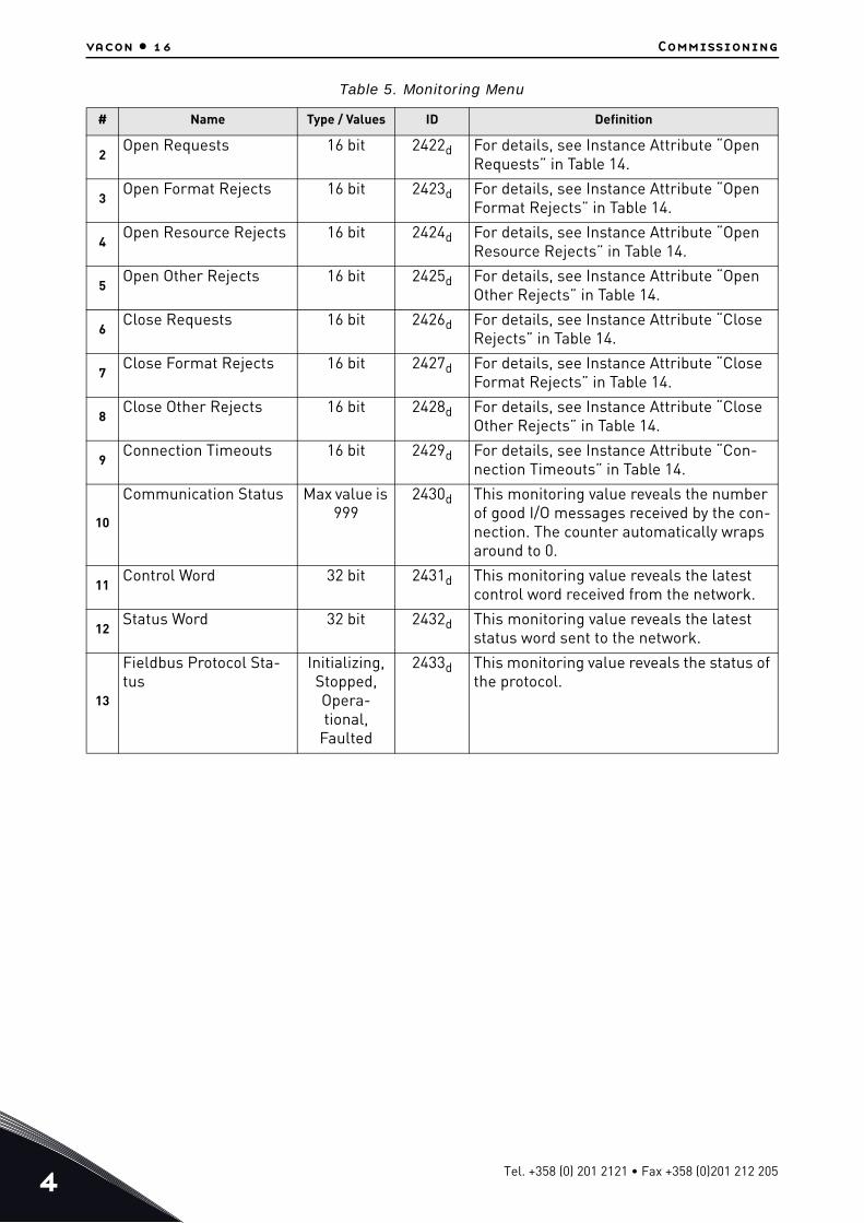
Table 5. Monitoring Menu
# Name Type / Values ID Definition
1 Reset Counters “Button” 2421d Resets monitoring counters.
Table 4. Parameters Menu
# Name DefaultRange /
Accepted Values
ID Definition
24-hour support +358 (0)201 212 575 • Email: [email protected]
4
vacon • 16 Commissioning
2Open Requests 16 bit 2422d For details, see Instance Attribute “Open
Requests” in Table 14.
3Open Format Rejects 16 bit 2423d For details, see Instance Attribute “Open
Format Rejects” in Table 14.
4Open Resource Rejects 16 bit 2424d For details, see Instance Attribute “Open
Resource Rejects” in Table 14.
5Open Other Rejects 16 bit 2425d For details, see Instance Attribute “Open
Other Rejects” in Table 14.
6Close Requests 16 bit 2426d For details, see Instance Attribute “Close
Rejects” in Table 14.
7Close Format Rejects 16 bit 2427d For details, see Instance Attribute “Close
Format Rejects” in Table 14.
8Close Other Rejects 16 bit 2428d For details, see Instance Attribute “Close
Other Rejects” in Table 14.
9Connection Timeouts 16 bit 2429d For details, see Instance Attribute “Con-
nection Timeouts” in Table 14.
10
Communication Status Max value is 999
2430d This monitoring value reveals the number of good I/O messages received by the con-nection. The counter automatically wraps around to 0.
11Control Word 32 bit 2431d This monitoring value reveals the latest
control word received from the network.
12Status Word 32 bit 2432d This monitoring value reveals the latest
status word sent to the network.
13
Fieldbus Protocol Sta-tus
Initializing,Stopped,Opera-tional,
Faulted
2433d This monitoring value reveals the status of the protocol.
Table 5. Monitoring Menu
# Name Type / Values ID Definition
Tel. +358 (0) 201 2121 • Fax +358 (0)201 212 205

EtherNet/IP connection example vacon • 17
24-hour support +358 (0)201 212 575 • Email: [email protected]
5. ETHERNET/IP CONNECTION EXAMPLE
Preparing the connection1. Set the EtherNet/IP as the active protocol from the panel parameters.2. Set proper IP addresses.3. Open a connection with the settings described in the table below.4. Before trying to run motor, see Chapter 10 "APPENDIX 2 - FIELDBUS PARAMETRISATION" for
information how to configure the drive.
1. Set control word to 0x0 (00000000)2. Set control word to 0x61 (01100001) (NetRef, NetCtrl and Run Fwd enabled)3. Drive status is: RUN4. Set speed reference to 0x05EE (=25%)5. Actual speed is 0x05EE (= 25% if MinFreq is 0Hz and MaxFreq is 50Hz)6. Set control word 0x60 (01100000)7. Drive status is: STOP
Figure 5. Configuration example from EIPScan Tool
Table 6.
Description Instance Size
Configuration instance 103d / 67h 0
Output instance 21d / 15h 4
Input instance 71d / 47h 4

EtherNet/IP vacon • 18
6. ETHERNET/IP
6.1 Overview
The EtherNet/IP (Ethernet/Industrial Protocol) is a communication system suitable for use in industrial environments. The EtherNet/IP allows industrial devices to exchange time-critical application information. These devices include simple I/O devices such as sensors/actuators, as well as complex control devices such as robots, programmable logic c ontrollers, welders, and process controllers.
The EtherNet/IP uses CIP (Control and Information Protocol), the common network, transport and application layers also shared by ControlNet and EtherNet/IP. The EtherNet/IP then makes use of standard Ethernet and TCP/IP technology to transport CIP communications packets. The result is a common, open application layer on top of open and highly popular Ethernet and TCP/IP protocols.
The EtherNet/IP Messaging Forms:
• Unconnected Messaging is used for connection establishment and for infrequent, low prior-ity messages.
• Connected Messaging utilizes resources which are dedicated in advance to a particular pur-pose such as real-time I/O data transfer. EtherNet/IP Messaging Connections.
• Explicit Messaging Connections are general purpose point-to-point connections. Messages are sent through the TCP protocol.
• Implicit (I/O Data) Connections are established to move application specific I/O Data at regu-lar intervals. They are often set up as one-to-many relationships in order to take full advan-tage of the producer-consumer multicast model. Implicit messages are sent through the UDP protocol.
6.2 AC/DC Drive Profile
VACON® 100 Family AC drives implement the CIP AC/DC drive profile.
In order to provide interoperability between devices from different manufacturers, there must be a defined "standard" in which those devices:
• exhibit the same behaviour• produce and/or consume the same basic set of I/O data• contain the same basic set of configurable attributes. The formal definition of this
information is known as a device profile.
6.3 EDS file
You can provide configuration support for your device by using a specially formatted ASCII file, re-ferred to as the EDS (Electronic Data Sheet). An EDS provides information about the device config-uration.
The information in an EDS allows configuration tools to provide informative screens that guide a user through the steps necessary to configure a device. An EDS provides all of the information nec-essary to access and alter the configurable parameters of a device.
You can download the EDS for VACON® 100 Family AC drives from Danfoss website (http://drives.danfoss.com).
24-hour support +358 (0)201 212 575 • Email: [email protected]
6
vacon • 19 EtherNet/IP
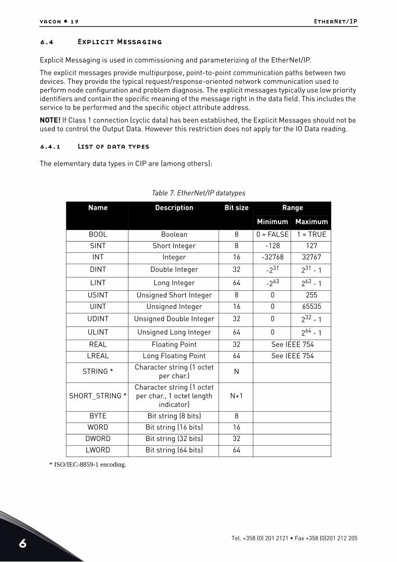
6.4 Explicit Messaging
Explicit Messaging is used in commissioning and parameterizing of the EtherNet/IP.
The explicit messages provide multipurpose, point-to-point communication paths between two devices. They provide the typical request/response-oriented network communication used to perform node configuration and problem diagnosis. The explicit messages typically use low priority identifiers and contain the specific meaning of the message right in the data field. This includes the service to be performed and the specific object attribute address.
NOTE! If Class 1 connection (cyclic data) has been established, the Explicit Messages should not be used to control the Output Data. However this restriction does not apply for the IO Data reading.
6.4.1 List of data types
The elementary data types in CIP are (among others):
* ISO/IEC-8859-1 encoding.
Table 7. EtherNet/IP datatypes
Name Description Bit size Range
Minimum MaximumBOOL Boolean 8 0 = FALSE 1 = TRUE
SINT Short Integer 8 -128 127
INT Integer 16 -32768 32767
DINT Double Integer 32 -231 231 - 1
LINT Long Integer 64 -263 263 - 1
USINT Unsigned Short Integer 8 0 255
UINT Unsigned Integer 16 0 65535
UDINT Unsigned Double Integer 32 0 232 - 1
ULINT Unsigned Long Integer 64 0 264 - 1
REAL Floating Point 32 See IEEE 754
LREAL Long Floating Point 64 See IEEE 754
STRING * Character string (1 octet per char.) N
SHORT_STRING *Character string (1 octet per char., 1 octet length
indicator)N+1
BYTE Bit string (8 bits) 8
WORD Bit string (16 bits) 16
DWORD Bit string (32 bits) 32
LWORD Bit string (64 bits) 64
Tel. +358 (0) 201 2121 • Fax +358 (0)201 212 205

EtherNet/IP vacon • 20
6.4.2 General CIP error codes
The table below contains the error codes used by EtherNet/IP.
Table 8. General CIP error codes
Code Status name Description0 Success Service was successfully performed by the object specified.
1 Connection failure A connection related service failed along the connection path.
2 Resource unavailable Resources needed for the object to perform the requested service were unavailable.
3 Invalid parameter value
See Status Code 0x20, which is the preferred value to use for this condition.
4 Path segment error The path segment identifier or the segment syntax was not understood by the processing node.
5 Path destination unknown
The path is referencing an object class, instance or struc-ture element that is not known or is not contained in the processing node.
6 Partial transfer Only part of the expected data was transferred.
8 Service not supported The requested service was not implemented or was not defined for this Object Class/Instance.
9 Invalid attribute value Invalid attribute data detected.
12d / 0Ch Object state conflict The object cannot perform the requested service in its cur-rent mode/state.
14d / 0Eh Attribute not settable A request to modify a non-modifiable attribute was received.
15d / 0Fh Privilege violation A permission/privilege check failed.
16d / 10h Device state conflict The device's current mode/state prohibits the execution of the requested service.
17d / 11h Reply data too large The data to be transmitted in the response buffer is larger than the allocated response buffer.
19d / 13h Not enough data The service did not supply enough data to perform the spec-ified operation.
20d / 14hAttribute not sup-
ported The attribute specified in the request is not supported.
21d / 15h Too much data The service supplied more data than was expected.
30d / 1EhEmbedded service
error An embedded service resulted in an error.
31d / 1Fh Vendor specific errorA vendor specific error has been encountered. The Addi-tional Code Field of the Error Response defines the particu-lar error encountered.
32d / 20h Invalid parameter A parameter associated with the request was invalid.
38d / 26h Path Size Invalid
The size of the path which was sent with the Service Request is either not large enough to allow the Request to be routed to an object or too much routing data was included.
24-hour support +358 (0)201 212 575 • Email: [email protected]
6
vacon • 21 EtherNet/IP
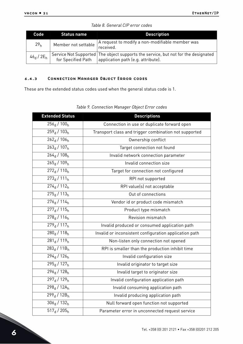
6.4.3 Connection Manager Object Error codes
These are the extended status codes used when the general status code is 1.
29h Member not settable A request to modify a non-modifiable member was received.
46d / 2EhService Not Supported
for Specified PathThe object supports the service, but not for the designated application path (e.g. attribute).
Table 9. Connection Manager Object Error codes
Extended Status Descriptions256d / 100h Connection in use or duplicate forward open
259d / 103h Transport class and trigger combination not supported
262d / 106h Ownership conflict
263d / 107h Target connection not found
264d / 108h Invalid network connection parameter
265d / 109h Invalid connection size
272d / 110h Target for connection not configured
273d / 111h RPI not supported
274d / 112h RPI value(s) not acceptable
275d / 113h Out of connections
276d / 114h Vendor id or product code mismatch
277d / 115h Product type mismatch
278d / 116h Revision mismatch
279d / 117h Invalid produced or consumed application path
280d / 118h Invalid or inconsistent configuration application path
281d / 119h Non-listen only connection not opened
283d / 11Bh RPI is smaller than the production inhibit time
294d / 126h Invalid configuration size
295d / 127h Invalid originator to target size
296d / 128h Invalid target to originator size
297d / 129h Invalid configuration application path
298d / 12Ah Invalid consuming application path
299d / 12Bh Invalid producing application path
306d / 132h Null forward open function not supported
517d / 205h Parameter error in unconnected request service
Table 8. General CIP error codes
Code Status name Description
Tel. +358 (0) 201 2121 • Fax +358 (0)201 212 205

EtherNet/IP vacon • 22
6.4.4 Supported CIP and Vendor Objects
The Communication Interface supports the following object classes.
789d / 315h Invalid segment in connection path
Range 320h – 7FFh are vendor specific800d / 320h Internal: Connection disabled
64258d / FB02h Internal: Bad socket
64259d / FB03h Internal: Bad originator to target net parameter
64260d / FB04h Internal: Bad target to originator net parameter
64261d / FB05h Internal: Bad UDP port
64262d / FB06h Internal: Join multicast
64263d / FB07h Internal: Prepare IO packet
64267d / FB0Bh Internal: Consumption
64268d / FB0Ch Internal: FW close
64270d / FB0Eh Internal: Adapter stopped
Table 10. CIP Objects
Type Class Object Details
Required by Ether-Net/IP
1 Identity Object See chapter 7.1.1
2 Message Router Object See chapter 7.1.2
4 Assembly Object See chapter 7.2.1
6 Connection Manager Object See chapter 7.1.3
245d / F5h TCP/IP Interface Object See chapter 7.1.4
246d / F6h Ethernet Link Object See chapter 7.1.5
Required by Drive Profile
40d / 28h Motor Data Object See chapter 7.2.2
41d / 29h Control Supervisor Object See chapter 7.2.3
42d / 2Ah AC/DC Drive Object See chapter 7.2.4
Vendor-Specific
160d / A0h Vendor Parameters Object See chapter 7.3.1
161d / A1h Motor Control Mode Object See chapter 7.3.3
162d / A2h Fault History Object See chapter 7.3.4
190d / BEhAssembly Instance Selector
Object See chapter 7.3.2
Table 9. Connection Manager Object Error codes
Extended Status Descriptions
24-hour support +358 (0)201 212 575 • Email: [email protected]

6
vacon • 23 EtherNet/IP
6.4.5 EtherNet/IP communication and connection timeout
The EtherNet/IP declares a watchdog the time within which both master and slave must send IO back to each other. This watchdog time is a factor of the communication cycle time (cycle time x timeout multiplier) and is set by the master. Minimum cycle time for VACON 100 EtherNet/IP is 4 milliseconds.
When an IO message is not received within the watchdog time, the timeout setting value is activated and a fault is created after it elapses. This means that the panel parameter "Communication timeout" (refer to chapter 4.2.4) is used as an additional timeout value. The same logic applies if a connection is closed or the cable disconnects (link loss).
Figure 6. EtherNet/IP timeout logic with implicit connection (IO connection)
The explicit connections (TCP connection where PLC/user reads and writes data via CIP objects) will generate fieldbus fault only if that connection has been used to write process data over Assembly, Control Supervisor or AC/DC object. The explicit connection timeout is defined with TCP/IP Object's attribute 13d "Encapsulation Inactivity Timeout".
We recommend that implicit connection is used for motor control and explicit connections for "service data".
Communicating
Received packet within watchdog time?
Communication timeout zero?
Has additionaltimeout elapsed?
Check
No
No
No
Yes
Yes
Implict Connectionestablished
FAULT!
Cable disconnectedConnection closed
11720_uk
Tel. +358 (0) 201 2121 • Fax +358 (0)201 212 205

EtherNet/IP vacon • 24
Figure 7. EtherNet/IP timeout logic with explicit connection
Communicating
Received packet within “TCP Inativity” time?
Has user written process data over this
connection
Communication timeout zero?
Has additionaltimeout elapsed?
Check
No
No
No
No
Yes
Yes
Yes
FAULT! Offline
Cable disconnectedConnection closed
11721_uk
24-hour support +358 (0)201 212 575 • Email: [email protected]

Common Industrial Objects implemented by vacon® 100 family vacon • 25
7. COMMON INDUSTRIAL OBJECTS IMPLEMENTED BY VACON®
100 FAMILY
7.1 CIP Common Required Objects
7.1.1 Identity Object, Class 0x01
The Identity Object provides identification of and general information about the device.
Table 11. Identity Object
Class name Identity ObjectClass identifier 1
Class Attributes
Id Access rule Name Datatype Description1 Get Revision UINT Class revision (1)
2 Get Max Instance UINT Maximum instance num-ber (1)
3 Get Number of Instances UINT Number of object
instances(1)
Class Ser-vices
Id Name Description1 Get_Attributes_All Get all attributes
14d 0Eh
Get_Attribute_Single Get single attribute
Instance Attributes
Id Access rule Name Datatype Description1 Get Vendor ID UINT Vendor identification
2 Get Device Type UINT General type of product
3 Get Product Code UINT Product identification
4 Get Revision STRUCT ofRevision of the item the
Identity Object repre-sents
Major Revision USINT
Minor Revision USINT
5 Status WORD Summary status of device
6 Serial number UDINT Serial number of the device
7 Product Name SHORT STRING
Human readable identifi-cation
Instance Services
Id Name Description1 Get_Attributes_All Get all attributes
5 Reset Only reset type 0
14d 0Eh
Get_Attribute_Single Get single attribute
24-hour support +358 (0)201 212 575 • Email: [email protected]
7
vacon • 26 Common Industrial Objects implemented by vacon® 100 family
7.1.1.1 Instance Attributes
Instance Attribute “Vendor ID”This number is assigned to vendors of CIP devices by the ODVA user organization. The vendor ID for VACON® is 01BBh(443d).
Instance Attribute “Device Type”This attribute indicates which device profile is implemented by the device. For VACON® drives this device number is 02h(“AC Drive” profile).
Instance Attribute “Product Code”This attribute reveals the vendor-assigned product code for a particular product within a device type.
Separate products must have different product codes if their configuration and/or runtime options are different.
The AC drive will return the product code value 64h(100d).
Instance Attribute “Revision”This attribute, which consists of the Major and Minor Revision fields, identifies the revision of the item/ device that the Identity Object is representing. The Major Revision is limited to values between 1 and 127, as the eighth bit is reserved by CIP and is zero.
Instance Attribute “Status”The value of the attribute presents the current status of the entire device. The coding of the field is defined in the table below.
Tel. +358 (0) 201 2121 • Fax +358 (0)201 212 205

Common Industrial Objects implemented by vacon® 100 family vacon • 27
The VACON® 100 Family AC drives drive implement bits 0, 2, and 4-11 according to the specification (Extended Device Status values 1, 4 and 8 to 15 are not used by VACON®). The bits 8-11 must be set according to the faults occurring in the drive.
Instance Attribute “Serial Number”This attribute can be used in conjunction with the Vendor ID to form a unique identifier for each device on any CIP network.
The serial number is formed so that the first octet is 00 and the last 3 octets are taken from the end of the MAC address of the drive. For example, when the MAC address is 00:21:99:AA:BB:CC, then the serial number would be 00AABBCCh.
Table 12. Status bit descriptions
Bit(s) Called Definition0 Owned TRUE, if device has owner
1 Reserved, is zero
2 Configured TRUE, if device has been configured (always true)
3 Reserved, is zero
4-7 Extended Device Status
Value Description0 Self-testing or unknown1 Firmware upgrade in progress2 At least one faulted I/O connection3 No I/O connections established4 Non-Volatile configuration bad5 Major fault - either bit 10 or bit 11 is true6 At least one I/O connection in run mode
7 At least one I/O connection established, all in idle mode
8The Status attribute is not applicable to this instance. Valid only for instances greater than one (1).
9 Reserved10 thru 15 Vendor specific, not used by VACON®
8 Minor Recover-able fault TRUE, if recoverable problem detected.
9 Minor Unrecov-erable Fault TRUE, if unrecoverable problem detected.
10 Major Recover-able Fault TRUE, if recoverable problem detected.
11 Major Unrecov-erable Fault TRUE, if unrecoverable problem detected.
12-15 Extended Device Status 2 Reserved, is zero
24-hour support +358 (0)201 212 575 • Email: [email protected]

7
vacon • 28 Common Industrial Objects implemented by vacon® 100 family
Instance Attribute “Product Name”This attribute contains human readable name identification for this instance. The value returned is “VACON® 100”.
7.1.1.2 Services
Instance Service “Reset”The VACON® 100 Family AC drives support only reset type 0.
The reset type 0 means that the device represented by the Identity Object will as closely as possible emulate the cycling of power.
If an error is detected, an error response is returned. Otherwise a successful Reset response is returned.
7.1.2 Message Router Object, Class 0x02
The Message Router Object is mandatory in all CIP devices. It provides a messaging connection point through which a Client may address a service to any object class or instance in a target device. Although the object is mandatory, there are no mandatory attributes or services.
The VACON® 100 Family AC drives do not currently implement any of the object’s services or attributes
7.1.3 Connection Manager Object, Class 0x06
The communication characteristics between the applications in different devices are modelled using Connection Objects. The entities (devices) involved in a connection are referred to as end-points. A Connection Manager is required in some CIP networks to control the aspects of Connection object instances.
The Connection Manager class allocates and manages the internal resources associated with both I/O and Explicit Messaging connections.
Table 13. Message router object
Class name Message Router ObjectClass identifier 2
Class Attributes
Id Access rule Name Datatype Description- - - - -
Class Ser-vices
Id Name Description- - -
Instance Attributes
Id Access rule Name Datatype Description- - - - -
Instance Services
Id Name Description- - -
Tel. +358 (0) 201 2121 • Fax +358 (0)201 212 205

Common Industrial Objects implemented by vacon® 100 family vacon • 29
Table 14. Connection manager object
Class name Connection Manager ObjectClass identifier 6
Class Attributes
Id Access rule Name Datatype Description1 Get Revision UINT Class revision (1)
2 Get Max Instance UINT Maximum instance number (1)
3 Get Number of Instances UINT Number of object
instances(1)
Class Ser-vices
Id Name Description
1 Get_Attributes_All Returns content of all (implemented) attributes in the class.
14d 0Eh
Get_Attribute_Single Used to read single attribute value.
Instance Attributes
Id Access rule Name Datatype Description
1 Get Open Requests UINT Number of Forward Open service requests received.
2 Get Open Format Rejects UINT
Number of Forward Open service requests which were rejected due to bad format.
3 Get Open Resource Rejects UINT
Number of Forward Open service requests which were rejected due to lack of resources.
4 Get Open Other Rejects UINT
Number of Forward Open service requests which were rejected for other reasons.
5 Get Close Requests UINT Number of Forward Close service requests received.
6 Get Close Format Rejects UINT
Number of Forward Close service requests which were rejected due to bad format.
7 Get Close Other Rejects UINT
Number of Forward Close service requests which were rejected for other reasons
8 Get Connection Timeouts UINT
Total number of connection timeouts that have occurred in connections controlled by this Connection Manager.
24-hour support +358 (0)201 212 575 • Email: [email protected]

7
vacon • 30 Common Industrial Objects implemented by vacon® 100 family
7.1.3.1 Services
Instance Service “Forward Open”The Forward Open service is used to open a connection to a target device. If the path between devices consists of multiple links, then local connections between these are also established.
The minimum time for the RPI (Request Packet Interval) is 4 ms. The connection object instance number is 103d (67h).
Instance Service “Forward Close”The Forward Close service is used to close a connection between two devices (and all nodes in the connection path).
7.1.4 TCP/IP Interface Object, Class 0xF5
The TCP/IP Interface Object provides an interface to configure the device’s TCP/IP settings. With this object, you can configure, for example, the device’s IP address, network mask and so on.
Instance Services
Id Name Description
1 Get_Attributes_All Returns content of all (implemented) attributes in the instance
14d 0Eh
Get_Attribute_Single Used to read the single attribute value
78d4Eh
Forward_Open Opens a connection (maximum data size is 511 bytes)
84d54h
Forward_Close Closes a connection
Table 15. TCP/IP interface object
Class name TCP / IP objectClass identifier 245d / F5h
Class Attributes
Id Access rule Name Datatype Description1 Get Revision UINT Class revision (4)
2 Get Max Instance UINT Maximum instance number (1)
3 Get Number of Instances UINT Number of object
instances(1)
Class Ser-vices
Id Name Description
1 Get_Attributes_All Returns content of all (implemented) attributes in the class.
14d 0Eh
Get_Attribute_Single Used to read single attribute value.
Table 14. Connection manager object
Tel. +358 (0) 201 2121 • Fax +358 (0)201 212 205

Common Industrial Objects implemented by vacon® 100 family vacon • 31
7.1.4.1 Instance Attributes
Instance Attribute “Status”This attribute presents the status of the TCP/IP network interface.
Instance Attributes
Id Access rule Name Datatype Description1 Get Status DWORD Interface status
2 Get Configuration Capability DWORD Interface capability flags
3 Get/set Configuration Control DWORD Interface control flags
4 Get Physical Link Object STRUCT of Path to physical link object
Path size UINT Size of the path
Path Padded EPATH
Logical segments identify-ing the physical link object
5 Get/set
Instance Config-uration STRUCT of TCP/IP network interface
configurationIP Address UDINT The device’s IP address
Network Mask UDINT The device’s network maskGateway Address UDINT Default gateway address
Name Server UDINT Primary name serverName Server 2 UDINT Secondary name serverDomain Name STRING Default domain name
6 Get/set Host Name STRING Host name10d / 0Ah
Get/set Select ACD BOOL Activates the use of ACD (enabled by default)
11d / 0Bh
Get
Last Conflict Detected
STRUCT of:
Structure containing infor-mation related to the last conflict detected.
ACD activity USINT State of ACD activity
Remote MAC Array of 6 USINT
MAC address of last conflict source.
ARP PDU Array of 28 USINT
Copy of the last ARP PDU in which a conflict was detected.
Instance Services
Id Name Description
1 Get_Attributes_All Returns content of all (implemented) attributes in the instance
14d 0Eh
Get_Attribute_Single Used to read single attribute value.
16d10h
Set_Attribute_Single Used to write a single attribute value.
Table 15. TCP/IP interface object
24-hour support +358 (0)201 212 575 • Email: [email protected]

7
vacon • 32 Common Industrial Objects implemented by vacon® 100 family
Instance Attribute “Configuration Capability”This attribute presents the capability flags (that is, the support for the optional network configuration capability) of the TCP/IP network interface.
Table 16. Status Bit Descriptions
Bit(s) Called Definition
0-3 Interface Con-figuration Status
Indicates the status of the
interface config-uration attribute
Value Definition
0 The Interface Configuration Attribute has not been configured
1
The Interface Configuration Attribute contains valid configura-tion obtained from BOOTP, DHCP or non-volatile storage.
2
The IP address member of the Interface Configuration Attribute contains valid configuration, obtained from hardware settings
3-15 Reserved for future use
4 Mcast Pending Indicates a pending configuration change in the TTL Value and/or Mcast Config attributes.
5Interface Con-
figuration Pend-ing
Indicates a pending configuration change in the Interface Con-figuration attribute.
6 AcdStatus Set(1) Address Conflict Detected, Clear(0) No Address Conflict Detected
7-31 Reserved Always zero
Table 17. Configuration capability bit descriptions
Bit(s) Called Definition0 BOOTP Client Supports BOOTP (FALSE)
1 DNS Client Supports capable of resolving DNS names (FALSE)
2 DHCP Client Supports DHCP (TRUE)3 DHCP-DNS Update Always zero4 Configuration Settable TRUE, if configuration settable
5 Hardware Configurable Configuration can be obtained from hardware settings (FALSE)
6 Interface Configuration Change Requires Reset Configuration change results in reset (FALSE)
7 AcdCapable Supports ACD (TRUE)8-31 Reserved Reserved, always zero
Tel. +358 (0) 201 2121 • Fax +358 (0)201 212 205

Common Industrial Objects implemented by vacon® 100 family vacon • 33
Instance Attribute “Configuration Control”This attribute allows control of the TCP/IP network interface configuration.
When using the Configuration Control attribute, the device can be configured to use statically assigned IP values or DHCP. If the value is changed from DHCP to statically assigned, the device will continue using the current IP address. When changing from statically assigned to DHCP, the drive will try to get an IP address from the DHCP server. If this fails, the communication with the drive cannot be re-opened and you must set the IP address manually from the panel or enable the DHCP server in the network.
Changing the Configuration Control is not allowed if the I/O connection is open.
In the VACON® 100 Family AC drives, the value of the Configuration Control is 0, when the “IP Address Mode” panel parameter is “Fixed IP”. If the “IP Address Mode” is “DHCP”, the value of the Configuration Control is 2.
The VACON® 100 Family AC drives do not support BOOTP or DNS.
Instance Attribute “Physical Link Object”This attribute identifies the object which is associated with the underlying physical communications interface (in the case of Ethernet, for example, the IEEE 802.3 interface). The attribute consists of two components; a Path Size, which reveals the number of UINT values in the path, and the Path itself.
In the VACON® 100 Family AC drives, the path points to an instance of the EtherNet Link Object. The value of the Path Size is 2 (total of four octets) and the value of the Path is 20h F6h 24h XXh, where XX is the instance number of the EtherNet Link object.
Instance Attribute “Instance Configuration”This attribute contains the configuration parameters required for a device to operate as a TCP/IP node. The contents of the attribute depend on how the device has been configured to obtain its IP parameters (the “Configuration Method” field in the Configuration Control attribute). If the device uses a static IP address (Configuration Method value is 0), the values in the Interface Configuration are those statically assigned and stored in the non-volatile memory. If the device uses DHCP (or BOOTP) (Configuration Method value is 1 or 2), the Interface Configuration values will contain the
Table 18. Configuration control bit descriptions
Bit(s) Called Definition
0-3 Configuration Method
Determines how the device
obtains its IP related configu-
ration
Value Definition
0 The device uses statically-assigned IP configuration values.
1 The device obtains its interface configuration values via BOOTP
2 The device obtains its interface configuration values via DHCP
3-15 Reserved for future use.
4 DNS Enable If TRUE, the device resolves host names by querying a DNS server
5-31 Reserved Reserved, always zero
24-hour support +358 (0)201 212 575 • Email: [email protected]

7
vacon • 34 Common Industrial Objects implemented by vacon® 100 family
configuration obtained through this channel. Until the BOOTP/DHCP reply is received, the values are 0.
Changing the Instance Configuration is not allowed when the I/O connection is open or Configuration Control-attribute is not set to “statically-assigned”.
The IP address, Network Mask and Gateway address consists of four bytes. For example, the IP address 192.168.0.10 would be in format: C0h, A8h, 00h, 0Ah.
Instance Attribute “Host Name”This attribute contains the device’s host name. The maximum length is 64 ASCII characters. The name is padded to an even number of characters. The Attribute Host Name is used only for information purpose.
Instance Attribute "Select ACD"This attribute is used to enable or disable ACD (Address Conflict Detection) functionality.
For more information see chapter 2.1.1.
Table 19. Instance configuration
Interface Configuration
STRUCT of: Description Semantics of the value
IP address UDINT The device's IP address
Value of 0 indicates no IP address has been configured. Otherwise, the IP address must be set to a valid Class A, B, or C address and must not be set to the loopback address (127.0.0.1).
Network Mask UDINT The Device's network mask
Value of 0 indicates no network mask address has been configured.
Gateway Address UDINT Default gateway
address
Value of 0 indicates no IP address has been configured. Otherwise, the IP address must be set to a valid Class A, B, or C address and must not be set to the loopback address (127.0.0.1).
Name Server UDINT Primary name server
Value of 0 indicates no name server address has been configured. Otherwise, the name server address must be set to a valid Class A, B, or C address.
Name Server 2 UDINT Secondary name server
Value of 0 indicates no secondary name server address has been configured. Oth-erwise, the name server address must be set to a valid Class A, B, or C address.
Domain Name STRING Default domain name
ASCII characters. Maximum length is 48 characters. Must be padded to an even number of characters (pad not included in length). A length of 0 indicates that no Domain Name is configured.
Tel. +358 (0) 201 2121 • Fax +358 (0)201 212 205

Common Industrial Objects implemented by vacon® 100 family vacon • 35
Instance Attribute "Last Conflict Detected"This attribute contains information of the last IP address conflict. The content of this attribute can be resetted by writing zero to this attribute.
The struct member "ACD Activity" tells the state of ACD algorithm when the last conflict was detected. Possible values are defined in the table below.
The struct member "Remote MAC" tells the MAC address the source of the last IP address conflict.
The struct member "ARP PDU" contains the ARP message (raw copy) received from the source of the IP address conflict. Content of the ARP message is described in the table below.
Instance Attribute “Encapsulation Inactivity Timeout”The Encapsulation Inactivity Timeout attribute is used to enable the TCP socket cleanup (closing) when the defined number of seconds have elapsed with no Encapsulation activity. The default value is 120 seconds. The TCP keep-alive traffic does not count as Encapsulation activity.
Table 20. ACD Activity values
Value ACD Mode Description
0 No conflict detected (default)
No conflict has been detected since this attribute was last cleared.
1 Probe IPV4 address Last conflict detected during IPV4 address probe state
2 Ongoing detection Last conflict detected during OngoingDetection-state or subsequent DefendWithPolicyB state
3 Semi active probe Last conflict detected furint SemiActiveProbe-state or subsequent DefendWithPolicyB-state
Table 21. The ARP PDU in binary format
Field size(bytes) Field Description
2 Hardware type (1 for Ethernet HW)
2 Protocol type (0x800 for IP)
1 Hardware size (6 for Ethernet HW)
1 Protocol size (4 for IP)
2 Operation code (1 for request or 2 for response)
6 Sender MAC address
4 Sender IP address
6 Target MAC address
4 Target IP address
24-hour support +358 (0)201 212 575 • Email: [email protected]

7
vacon • 36 Common Industrial Objects implemented by vacon® 100 family
7.1.5 Ethernet Link Object, Class 0xF6
Ethernet Link Object provides interface to Ethernet link counters and attributes. With this object, user can retrieve for example link speed.
Table 22.
Value Description0 Disable
1-3600 Timeout in seconds
Table 23. Ethernet Link Object
Class name Ethernet Link ObjectClass identifier 246d / F6h
Class Attributes
Id Access rule Name Datatype Description1 Get Revision UINT Class revision (4)
2 Get Max Instance UINT Maximum instance number (1)
3 Get Number of Instances UINT Number of object
instances(1)
Class Ser-vices
Id Name Description
1 Get_Attributes_All Returns content of all (implemented) attributes in the class.
14d 0Eh
Get_Attribute_Single Used to read single attribute value.
Tel. +358 (0) 201 2121 • Fax +358 (0)201 212 205

Common Industrial Objects implemented by vacon® 100 family vacon • 37
7.1.5.1 Instance Attributes
Instance Attribute “Interface Speed”The attribute reveals the currently used speed in the interface. The speed is announced as an integer number, with the unit Mbps, e.g. 0, 10, 100 etc. The value 0 indicates that the interface speed is indeterminate.
Instance Attribute “Interface Flags”The attribute contains status and configuration information about the physical interface.
Instance Attributes
Id Access rule Name Datatype Description
1 Get Interface Speed UDINT Interface speed currently in use
2 Get Interface Flags DWORD Interface status flags
3 Get Physical Address
ARRAY of 6 USINTs MAC layer address
4 Get Interface Coun-ters
STRUCT of 11 UDINTs
Interface counters. See Table 25
5 Get Media Counters STRUCT of 12 UDINTs
Media specific counters. See Table 26
7 Get Interface Type USINT Type of interface: twisted pair, fiber, internal, etc
8 Get Interface State USINTCurrent state of the inter-face: operational, disabled, etc
9 Get/Set Admin State USINT Administrative state: ena-ble, disable
10d0Ah
Get Interface Label SHORT STRING
Human readable identifica-tion
Instance Services
Id Name Description
1 Get_Attributes_All Returns content of all (implemented) attributes in the instance
14d 0Eh
Get_Attribute_Single Used to read single attribute value
16d10h
Set_Attribute_Single Used to write a single attribute value.
76d4Ch
Get_and_ClearGets then clears the specified attribute (Interface Counters, Media Counters). Not instance/class dependent service.
Table 23. Ethernet Link Object
24-hour support +358 (0)201 212 575 • Email: [email protected]

7
vacon • 38 Common Industrial Objects implemented by vacon® 100 family
Instance Attribute “Physical Address”The attribute reveals the MAC layer address of the physical interface.
Instance Attribute “Interface Counters”The attribute is a collection of counters related to the Ethernet physical interface. Only packets sent or received by the device itself are counted.
Table 24. Interface flag bit descriptions
Bit(s) Called Definition0 Link Status One, if link is active
1 Half/Full Duplex One, if full duplex
2-4 Negotiation Sta-tus
Value Definition0 Auto-negotiation in progress
1Auto-negotiation and speed detection failed. Using default values for speed and duplex.
2 Auto-negotiation failed but detected speed. Duplex was defaulted.
3 Successfully negotiated speed and duplex.
4 Auto-negotiation not attempted. Forced speed and duplex.
5 Manual Setting Requires Reset
0 indicates the interface can automatically activate changes to link parameters (auto-negotiate, duplex
mode, interface speed). 1 indicates the device requires a Reset service be issued to its Identity
Object in order for the changes to take effect.
6 Local Hardware Fault
0 indicates the interface detects no local hardware fault; 1 indicates a local hardware fault is detected.
7-31 Reserved Always zero
Table 25. Interface counters
Field name Data type Description
In Octets UDINT The number of octets received on the inter-face (including framing characters).
In Unicast Packets UDINT The number of unicast packets received on the interface.
In NonUnicast Packets UDINT The number of non-unicast packets received on the interface.
In Discards UDINT Inbound packets received on the interface but which were discarded.
Tel. +358 (0) 201 2121 • Fax +358 (0)201 212 205

Common Industrial Objects implemented by vacon® 100 family vacon • 39
Instance Attribute “Media Counters”The attribute is a collection of counters related to the Ethernet physical interface.
In Errors UDINT Inbound packets received on the interface but which contained errors (excluding Discards).
In Unknown Protocols UDINT Inbound packets received on the interface which belonged to unknown protocols.
Out Octets UDINT The number of octets sent on the interface (including framing characters).
Out Unicast Packets UDINTThe number of unicast packets requested to
be transmitted on the interface, including those that were discarded or not sent.
Out NonUnicast Pack-ets UDINT
The number of non-unicast packets requested to be transmitted on the interface, including
those that were discarded or not sent.
Out Discards UDINT Outbound packets which were discarded.
Out Errors UDINT Outbound packets which contained errors (excluding Discards).
Table 26. Media counters
Field name Data type Description
Alignment Errors UDINT Frames received that are not an integral number of octets in length.
FCS Errors UDINT Frames received that do not pass the FCS check.
Single Collisions UDINT Successfully transmitted frames which experienced exactly one collision.
Multiple Collisions UDINT Successfully transmitted frames which experienced more than one collision.
SQE Test Errors UDINT The number of times SQE test error message is generated.
Deferred Transmis-sions UDINT Frames for which the first transmission attempt is
delayed because the medium is busy.
Late Collisions UDINT Number of times a collision is detected later than 512 bit-times into the transmission of a packet.
Excessive Collisions UDINT Frames for which transmission fails due to exces-sive collisions.
MAC Transmit Errors UDINT Frames for which transmission fails due to an inter-nal MAC sub layer transmit error.
Carrier Sense Errors UDINTTimes that the carrier sense condition was lost or
never asserted when attempting to transmit a frame.
Frame Too Long UDINT Frames received that exceed the maximum permit-ted frame size.
Table 25. Interface counters
Field name Data type Description
24-hour support +358 (0)201 212 575 • Email: [email protected]

7
vacon • 40 Common Industrial Objects implemented by vacon® 100 family
Instance Attribute “Interface Type”The attribute indicates the type of the Ethernet interface, i.e. twisted-pair cable, optical fiber, device-internal etc. The AC drive will always return the value 2, twisted-pair cable.
Instance Attribute “Interface State”The attribute indicates the current state of the Ethernet interface, i.e. operational, disabled etc.
Instance Attribute “Admin State”The attribute indicates the ability to use the Ethernet interface for administration, for example, for changing the settings.
The VACON® 100 Family AC drives support this attribute with the value 01h (administration enabled). An attempt to disable the administration (by writing value 02h) will result in an error.
MAC Receive Errors UDINT Frames for which reception on an interface fails due to an internal MAC sub layer receive error.
Table 27. Interface state
Value Interface state0 Unknown interface state
1 The interface is enabled and is ready to send and receive data
2 The interface is disabled3 The interface is testing
4-255 Reserved
Table 26. Media counters
Field name Data type Description
Tel. +358 (0) 201 2121 • Fax +358 (0)201 212 205

Common Industrial Objects implemented by vacon® 100 family vacon • 41
7.2 Objects Present in an AC/DC Drive
7.2.1 Assembly Object, Class 0x04
The assembly object groups (or assembles) the attribute values into a single block of data.
7.2.1.1 Instance Attributes
Instance Attribute “Data”This attribute can be used to get assembly data. The content and length of the data depends on the configuration of the assembly instance.
7.2.2 Motor Data Object, Class 0x28
Motor Data Object provides interface to the motor data attributes, for example “motor type”.
Table 28. Assembly object
Class name Assembly objectClass identifier 4
Class Attributes
Id Access rule Name Datatype Description1 Get Revision UINT Class revision (2)
2 Get Max Instance UINTMaximum instance num-
ber (137h)
3 Get Number of Instances UINT Number of object
instances(17)
Class Ser-vices
Id Name Description
1 Get_Attributes_All Returns content of all (implemented) attributes in the class.
14d 0Eh
Get_Attribute_Single Used to read single attribute value.
Instance Attributes
Id Access rule Name Datatype Description
3 Set Data ARRAY of BYTE Assembly data
Instance Services
Id Name Description14d 0Eh
Get_Attribute_Single Used to read single attribute value
16d10h
Set_Attribute_Single Used to write a single attribute value
Table 29. Motor data object
Class name Motor data objectClass identifier 40d / 28h
24-hour support +358 (0)201 212 575 • Email: [email protected]

7
vacon • 42 Common Industrial Objects implemented by vacon® 100 family
7.2.2.1 Instance Attributes
Instance Attribute “MotorType”The VACON® 100 Family AC drives support values 3 (Permanent Magnet Synchronous Motor) and 7 (Squirrel Cage Induction Motor).
Instance Attribute “RatedCurrent”This attribute allows reading and writing of the motor rated current. The unit of the attribute is 100 milliamperes.
Instance Attribute “RatedVoltage”This attribute allows reading and writing of the motor rated voltage. The unit of the attribute is 1 volt.
Instance Attribute “RatedFreq”This attribute allows reading and writing of the motor rated electrical frequency. The unit of the attribute is 1 hertz.
Class Attributes
Id Access rule Name Datatype Description- - - - -
Class Ser-vices
Id Name Description- - -
Instance Attributes
Id Access rule Name Datatype Description3 Get/Set MotorType USINT Motor type
6 Get/Set RatedCurrent UINT Rated Stator Current Units: [100mA]
7 Get/Set RatedVoltage UINT Rated Base Voltage Units: [V]
9 Get/Set RatedFreq UINT Rated Electrical Fre-quency Units: [Hz]
12d 0Ch
Get PoleCount UINT Number of poles in the motor.
15d 0Fh
Get/Set Base Speed UINTNominal speed at rated frequency from name-plate Units: [RPM]
Instance Services
Id Name Description14d 0Eh
Get_Attribute_Single Used to read single attribute value.
16d10h
Set_Attribute_Single Used to write a single attribute value.
Table 29. Motor data object
Tel. +358 (0) 201 2121 • Fax +358 (0)201 212 205
Common Industrial Objects implemented by vacon® 100 family vacon • 43
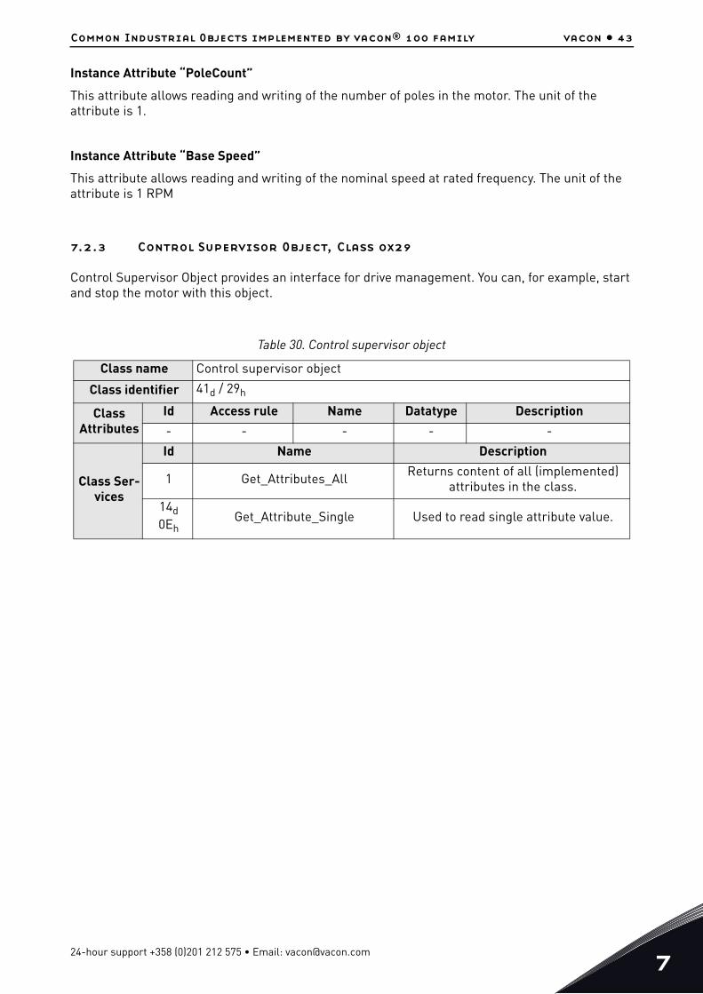
Instance Attribute “PoleCount”This attribute allows reading and writing of the number of poles in the motor. The unit of the attribute is 1.
Instance Attribute “Base Speed”This attribute allows reading and writing of the nominal speed at rated frequency. The unit of the attribute is 1 RPM
7.2.3 Control Supervisor Object, Class 0x29
Control Supervisor Object provides an interface for drive management. You can, for example, start and stop the motor with this object.
Table 30. Control supervisor object
Class name Control supervisor objectClass identifier 41d / 29h
Class Attributes
Id Access rule Name Datatype Description- - - - -
Class Ser-vices
Id Name Description
1 Get_Attributes_All Returns content of all (implemented) attributes in the class.
14d 0Eh
Get_Attribute_Single Used to read single attribute value.
24-hour support +358 (0)201 212 575 • Email: [email protected]

7
vacon • 44 Common Industrial Objects implemented by vacon® 100 family
7.2.3.1 Instance Attributes
Instance Attribute “Run1”This attribute affects the run/stop behavior of the drive. See Table 31.
Instance Attribute “Run2”This attribute affects the run/stop behavior of the drive. See Table 31.
Instance Attributes
Id Access rule Name Datatype Description3 Get/Set Run1 BOOL Run forward4 Get/Set Run2 BOOL Run reverse
5 Get/Set NetCtrl BOOL Request Run/Stop control to be local or from network
6 Get State USINT State. See Table 32.7 Get Running1 BOOL True, when running forward
8 Get Running2 BOOL True, when running in reverse
9 Get Ready BOOL True, when Ready or Ena-bled or Stopping
10d 0Ah
Get Faulted BOOL True, when fault is active
11d 0Bh
Get Warning BOOL True, when warning/alarm is active
12d 0Ch
Get/Set FaultRst BOOL Resets fault when transits from zero to one
13d 0Dh
Get FaultCode UINT
If in Faulted-state, Fault-Code indicates the active fault. Otherwise last error or zero after startup.
15d 0Fh
Get CtrlFromNet BOOLTrue, control is from net-workFalse, control is local.
21d 15h
Get/Set NetIdleMode USINT Mode on reception of CIP communication IDLE event.
Instance Services
Id Name Description5 Reset Resets drive to startup state.
14d 0Eh
Get_Attribute_Single Used to read single attribute value.
16d10h
Set_Attribute_Single Used to write a single attribute value.
Table 30. Control supervisor object
Tel. +358 (0) 201 2121 • Fax +358 (0)201 212 205

Common Industrial Objects implemented by vacon® 100 family vacon • 45
Instance Attribute “NetCtrl”This attribute allows the network to request the run/stop control to be assigned to the network. If the bit is 0, given control word is not updated to the drive. If the bit is 1, this means that the run/stop control is requested to this network interface.
NOTE! The actual assignment of the run/stop control to this network interface is reflected in attribute 15d.
The AC drive will not force control to the network. You must change the control location (fieldbus/IO/keypad) from the drive parameters.
Instance Attribute “State”This attribute reveals the state of the device according to the table below. See also chapter 7.2.3.3.
Instance Attribute “Running1”This attribute is used to describe the run state of the drive. The value of the attribute is 1, if one of the below conditions are fulfilled:
• The “State” attribute has the value 4 (“Enabled”) and the bit “Run1” has the value 1, or• The “State” attribute has the value 5 (“Stopping”) and the bit “Running1” has the value 1, or• The “State” attribute has the value 6 (“Fault_Stop”) and the bit “Running1” has the value 1
Otherwise, the value of this attribute is 0.
Table 31. Run/Stop Event Matrix
Run1 Run2 Trigger event Run type0 0 Stop N/A
0 -> 1 0 Run Run1
0 0 -> 1 Run Run2
0 -> 1 0 -> 1 No Action N/A
1 1 No Action N/A
1 -> 0 1 Run Run2
1 1 -> 0 Run Run1
Table 32. State Value Descriptions
Value Definition0 Vendor Specific
1 Startup
2 Not_Ready
3 Ready
4 Enabled
5 Stopping
6 Fault_Stop
7 Faulted
24-hour support +358 (0)201 212 575 • Email: [email protected]

7
vacon • 46 Common Industrial Objects implemented by vacon® 100 family
Instance Attribute “Running2”This attribute is used to describe the run state of the drive. The value of the attribute is 1, if one of the below conditions are fulfilled:
• The “State” attribute has the value 4 (“Enabled”) and the bit “Run2” has the value 1, or• The “State” attribute has the value 5 (“Stopping”) and the bit “Running2” has the value 1, or• The “State” attribute has the value 6 (“Fault_Stop”) and the bit “Running2” has the value 1
Otherwise, the value of this attribute is 0.
Instance Attribute “Ready”This attribute is used to signal the state of the drive that it is ready for operation. The value of the attribute is 1 if the value of the “State” attribute is either 3 (“Ready”), 4 (“Enabled”) or 5 (“Stopping”). Otherwise the value of this attribute is 0.
Instance Attribute “Faulted”This attribute is used to signal that one or several faults have occurred in the drive. The value of the attribute is 1 if a fault has occurred and has not been acknowledged. Otherwise, the attribute has the value 0 indicating that no faults are present.
Instance Attribute “Warning”This attribute is used to signal that one or several warnings have appeared in the drive. The value of the attribute is 1 if a warning has appeared and has not been acknowledged. Otherwise, the attribute has the value 0 indicating that no warnings are present.
Instance Attribute “FaultRst”This attribute is used to reset faults and warnings in the drive. The attribute is write-only. Changing the value of the attribute from 0 to 1 (rising-edge) resets the faults in the drive. If the value is static 0, no reset action is started.
Instance Attribute “FaultCode”This attribute is used to read the kind of fault which has caused the device to transition into the “Faulted” state. In the case of multiple faults occurring simultaneously, only one code is reported. If the device is not in the Faulted state, the FaultCode attribute indicates the fault which caused the last transition to the Faulted state.
Instance Attribute “CtrlFromNet”It indicates whether the run/stop control is assigned to the local interface or to this network interface. When the value of the attribute is 0, the control is local. When the value of the attribute is 1, the run/stop control is assigned to the network interface.
Instance Attribute "NetIdleMode"This attribute establishes the mode of operation on reception of network idle communication. Default value for this attribute is zero. Possible values are listed in the table below.
Tel. +358 (0) 201 2121 • Fax +358 (0)201 212 205

Common Industrial Objects implemented by vacon® 100 family vacon • 47
7.2.3.2 Services
Instance Service “Reset”The Control Supervisor Object has a instance service named “Reset” which has the Service Code 05h. The service resets the drive to the start-up state.
If an error is detected, an error response is returned. Otherwise a successful Reset response is returned.
7.2.3.3 Control Supervisor State Machine
The Control Supervisor Object defines a state machine for governing the behaviour of devices. The figure below describes the states and transitions of the state machine.
Figure 8. Control Supervisor State Machine
Table 33. NetIdleMode values
Mode Action Error/Warning0 Stops motor Fault
1 Ignored. IO data is not used, drive stays in state which was active before reception of IDLE -
2Vendor specific, fieldbus fault is activated (actual
behavior depends on drive application and parametrization).
Fault
Other values are not supported
7082_UK
Non-existent
Startup FaultedMain Power Off
Fault_Stop
Not_Ready
Enabled
Stopping
Ready
Reset
Switch On
Switch Off
Fault Detected
Initialisation Complete
Fault Detected
Fault_StopComplete
FaultDetected
Main Power OffMain Power On
RunStop
StopComplete
Fault Reset
24-hour support +358 (0)201 212 575 • Email: [email protected]

7
vacon • 48 Common Industrial Objects implemented by vacon® 100 family
7.2.4 AC/DC Drive Object, Class 0x2A
The AC/DC Drive Object models the functions specific to an AC or DC drive.
Table 34. AC/DC drive object
Class name AC/DC drive objectClass identifier 42d / 2Ah
Class Attributes
Id Access rule Name Data-type Description
- - - - -
Class Ser-vices
Id Name Description- - -
Tel. +358 (0) 201 2121 • Fax +358 (0)201 212 205

Common Industrial Objects implemented by vacon® 100 family vacon • 49
Instance Attributes
Id Access rule Name Data-type Description
3 Get/Set AtReference BOOLTrue, when drive actual at reference (speed or torque reference) based on mode
4 Get/Set NetRef BOOL
Requests torque or speed reference to be from the network.False, when Set Reference not DN ControlTrue, when Set Reference at DN Control
5 Get/Set NetProc BOOL
Requests process control reference to be from the network.False, when Set Process not DN ControlTrue, when Set Process at DN Con-trol
6 Get DriveMode USINT Drive mode. See Table 35.
7 Get SpeedActual INTActual drive speed Units: RPM / 2SpeedScale where SpeedScale is attribute 22d
8 Get SpeedRef INTSpeed referenceUnits: RPM / 2SpeedScale
where SpeedScale is attribute 22d
11d 0Bh
Get TorqueActual INTActual torqueUnits: Nm / 2TorqueScale
where TorqueScale is attribute 24d
12d 0Ch
Get/Set TorqueRef INTTorque referenceUnits: Nm / 2TorqueScale
where TorqueScale is attribute 24d
13d 0Dh
Get ProcessActual INTActual process control valueUnits: %ProcessScale is not supported.
14d 0Eh
Get/Set ProcessRef INTProcess control reference set point. Units: % ProcessScale is not supported
22d16h
Get/Set SpeedScale SINT
Speed scaling factor. Scaling isaccomplished as follows:ScaledSpeed = RPM / 2SpeedScale Range: -4 .. 7
24d18h
Get/Set TorqueScale
Torque scaling factor. Scaling isaccomplished as follows:ScaledTorque = Nm / 2TorqueScale Range: -8 .. 7
29d1Dh
Get RefFromNet BOOL
Status of torque/speed referenceFalse, when local torque/speed ref-erence. True, when network torque/speed reference
Table 34. AC/DC drive object
24-hour support +358 (0)201 212 575 • Email: [email protected]

7
vacon • 50 Common Industrial Objects implemented by vacon® 100 family
7.2.4.1 Instance Attributes
Instance Attribute “AtReference”This attribute indicates whether the actual value is at the reference value (e.g. the drive actual speed is the same as what is requested in the speed reference). If the bit is 1, the drive actual value is at the reference value.
Instance Attribute “NetRef”When the bit is 1, the torque or speed reference is requested to be allocated to this network interface. If the bit is 0, then no such request is made.
NOTE! The actual assignment of the reference to this network interface is reflected in the attribute 29d.
Instance Attribute “NetProc”This attribute is used to request torque or speed reference to be local or from network. Values are:
• 0 = Set reference not DN control• 1 = Set reference at DN control
Instance Attribute “DriveMode”Allowed values for Drive Mode defined in the table below.
NOTE! The actual drive mode support depends on the used drive and application. Check the actual drive mode support from the drive application manual.
Changes to DriveMode attribute must be reflected in the “Motor Control Mode Object”. The drive will respond with “Invalid attribute value” status code 0x09, if other values are written.
Instance Services
Id Name Description14d 0Eh
Get_Attribute_Single Used to read single attribute value.
16d10h
Set_Attribute_Single Used to write a single attribute value.
Table 35. Supported Drive Modes
Value Name Supported0 Vendor-specific mode Yes (Open loop frequency)
1 Open loop speed Yes (Open loop speed)
2 Closed loop speed control Yes (Closed loop speed)
3 Torque control Yes (Open loop torque)
4 Process control (e.g. PI control) No
5 Position control No
Table 34. AC/DC drive object
Tel. +358 (0) 201 2121 • Fax +358 (0)201 212 205

Common Industrial Objects implemented by vacon® 100 family vacon • 51
Instance Attribute “SpeedActual”This attribute allows reading of the speed actual value. The unit of the attribute must be (RPM / 2SpeedScale), where the SpeedScale is attribute 22d.
If the SpeedScale attribute is not used by the master, the default unit [1 RPM] is assumed. This is equivalent to the value 0 being used for the SpeedScale.
Instance Attribute “SpeedRef”This attribute allows reading and writing of the speed reference set point. The unit of the attribute must be (RPM / 2SpeedScale), where SpeedScale is attribute 22d.
If the SpeedScale attribute is not used by the master, the default unit [1 RPM] is assumed. This is equivalent to the value 0 being used for SpeedScale.
Instance Attribute “TorqueActual”This attribute allows reading of the torque actual value. The unit of the attribute must be (Nm / 2TorqueScale), where the TorqueScale is attribute 24d.
If the TorqueScale attribute is not used by the master, the default unit [1 Nm] is assumed. This is equivalent to the value 0 being used for the TorqueScale.
Instance Attribute “TorqueRef”This attribute allows reading and writing of the torque reference set point. The unit of the attribute must be (Nm / 2TorqueScale), where the TorqueScale is attribute 24d.
If the TorqueScale attribute is not used by the master, the default unit [1 Nm] must be assumed. This is equivalent to the value 0 being used for TorqueScale. To set the drive to the torque control, see Chapter 10 "APPENDIX 2 - FIELDBUS PARAMETRISATION".
Instance Attribute “ProcessActual”This attribute allows reading of the process actual value. The unit of the attribute must be (% / 2ProcessScale), where the ProcessScale is attribute 25d. The VACON® 100 Family EtherNet/IP does not support ProcessScale.
Instance Attribute “ProcessRef”This attribute allows reading and writing of the process reference set point. The unit of the attribute must be (% / 2ProcessScale), where ProcessScale is attribute 25d. The VACON® 100 Family EtherNet/IP does not support ProcessScale.
Instance Attribute “SpeedScale”The SpeedActual and SpeedRef values are scaled according to the value of this attribute. The default value is 0d.
The largest allowed value for this attribute in the VACON® 100 Family AC drives is 7 (allowing resolution of 0.0078 RPM) and the minimum allowed value is -4 (allowing resolution of 16 RPM). The maximum speed value for input/output is thus ca 524000 RPM.
24-hour support +358 (0)201 212 575 • Email: [email protected]

7
vacon • 52 Common Industrial Objects implemented by vacon® 100 family
Instance Attribute “TorqueScale”The TorqueActual and TorqueRef values are scaled according to the value of this attribute. The default value is 0d.
The largest allowed value for this attribute in the VACON® 100 Family AC drives is 7 (allowing resolution of 0.0078 Nm) and the minimum allowed value is -8 (allowing resolution of 256 Nm). The maximum torque value for input/output is thus ca 8.4 MNm.
Instance Attribute “RefFromNet”This attribute reveals whether the torque or speed reference is local or from the network. If the reference is local, the value of the attribute is 0. If the reference is from the network, then the value of the attribute is 1.
7.3 Vendor Specific Objects
7.3.1 Vendor Parameters Object, Class 0xA0
The Vendor Parameters Object is a vendor-specific object which allows the user to access any application parameter from the drive.
7.3.1.1 Instance Attributes
Instance Attribute “Parameter Value”If you want to read the value of a drive parameter, for example ,“Motor control mode” ID600d, set the instance attribute to value 600d and the instance number to 1 to the request. The data type of the parameter value can be 8, 16 or 32 bits.
Table 36. Vendor parameter object
Class name Vendor parameter objectClass identifier 160d / A0h
Class Attributes
Id Access rule Name Datatype Description- - - - -
Class Ser-vices
Id Name Description- - -
Instance Attributes
Id Access rule Name Datatype Description
XX Get/Set Parameter Value UINT Parameter Value
Instance Services
Id Name Description14d 0Eh
Get_Attribute_Single Used to read single attribute value.
16d10h
Set_Attribute_Single Used to write a single attribute value.
Tel. +358 (0) 201 2121 • Fax +358 (0)201 212 205

Common Industrial Objects implemented by vacon® 100 family vacon • 53
The VACON® 100 Family AC drives also support an old method from the OPTCQ option board of reading/writing ID values when the PLC supports only 8 bit instance attributes. This method is bit more complex.
In this mode, set the instance number to high octet of the ID, and the instance attribute as low octet of the ID. For example, if you want to read the value of ID 2291d (08F3h), the Get_Attribute_Single service request is targeted at the Vendor Parameters class, instance 08h and attribute F3h.
7.3.1.2 Services
Instance Service “Get_Attribute_Single”When invoked in an instance, the parameter ID to be fetched from the drive is calculated, then the read operation is started and once available, a response is provided to the master.
The format of the message is as follows:
The old format of the message is as follows (OPTCQ option board):
Instance Service “Set_Attribute_Single”When invoked in an instance, the parameter ID to be modified in the drive is calculated. The data type, write permission etc. are verified before the write operation is started. When the operation finishes, or if an error occurs, an appropriate response is provided to the master.
The format of the message is as follows:
Table 37.
Field Data
Service Code 0Eh
Class Code A0h
Instance Number 01h
Attribute ID XXXXh
Table 38.
Field Data
Service Code 0Eh
Class Code A0h
Instance Number YYh
Attribute ID XXh
Table 39.
Field Data
Service Code 10h
Class Code A0h
Instance Number 01h
24-hour support +358 (0)201 212 575 • Email: [email protected]

7
vacon • 54 Common Industrial Objects implemented by vacon® 100 family
The old format of the message is as follows (OPTCQ option board):
7.3.2 Assembly Instance Selector Object, Class 0xBE
The Assembly Instance Selector Object is a vendor-specific object which allows the user to get and set the input and output instances used.
The VACON® 100 Family AC drives will automatically change the current assembly instances by what is requested in the connection opening. This means that it is not mandatory to pre-set assembly instances.
Attribute ID XXXXh
Attribute Data Parameter-specific
Table 40.
Field Data
Service Code 10h
Class Code A0h
Instance Number YYh
Attribute ID XXh
Attribute Data Parameter-specific
Table 41. Assembly instance selector object
Class name Assembly instance selector objectClass identifier 190d / BEh
Class Attributes
Id Access rule Name Datatype Description- - - - -
Class Ser-vices
Id Name Description- - -
Instance Attributes
Id Access rule Name Datatype Description3 Get/Set InputInstance USINT Input assembly instance
4 Get/Set OutputInstance USINT Output assembly instance
Instance Services
Id Name Description14d 0Eh
Get_Attribute_Single Used to read single attribute value.
16d10h
Set_Attribute_Single Used to write a single attribute value.
Table 39.
Field Data
Tel. +358 (0) 201 2121 • Fax +358 (0)201 212 205
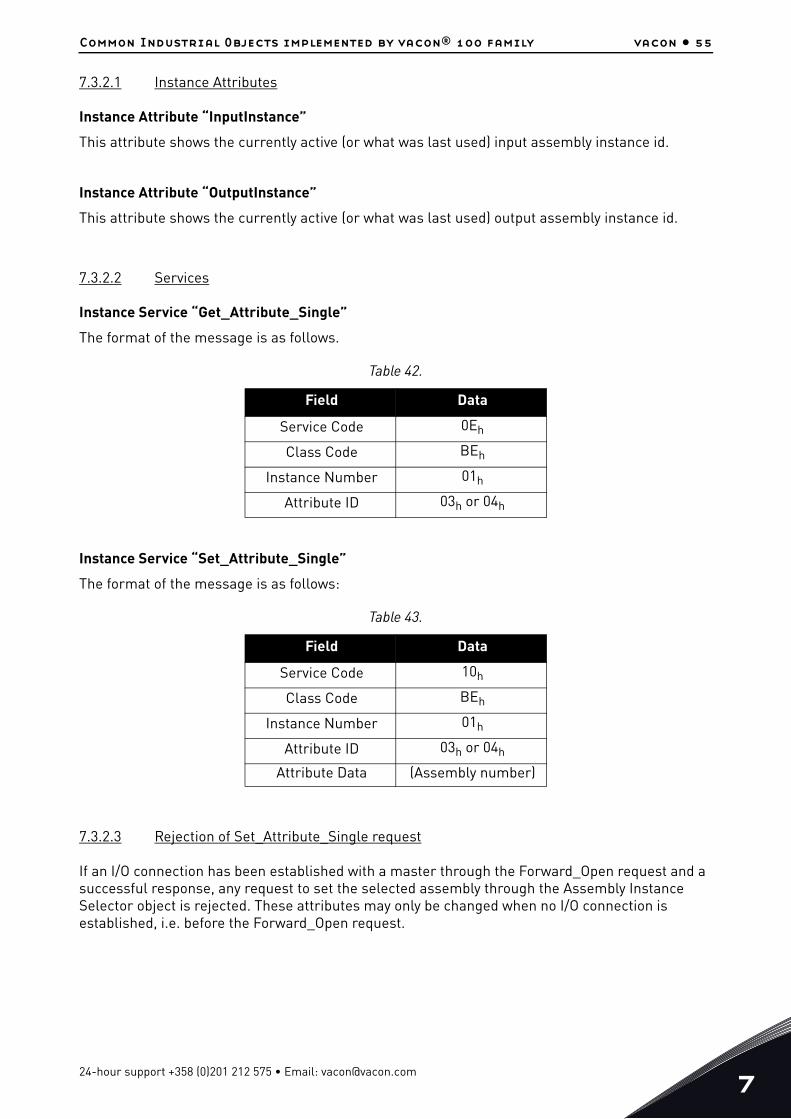
Common Industrial Objects implemented by vacon® 100 family vacon • 55
7.3.2.1 Instance Attributes
Instance Attribute “InputInstance”This attribute shows the currently active (or what was last used) input assembly instance id.
Instance Attribute “OutputInstance”This attribute shows the currently active (or what was last used) output assembly instance id.
7.3.2.2 Services
Instance Service “Get_Attribute_Single”The format of the message is as follows.
Instance Service “Set_Attribute_Single”The format of the message is as follows:
7.3.2.3 Rejection of Set_Attribute_Single request
If an I/O connection has been established with a master through the Forward_Open request and a successful response, any request to set the selected assembly through the Assembly Instance Selector object is rejected. These attributes may only be changed when no I/O connection is established, i.e. before the Forward_Open request.
Table 42.
Field Data
Service Code 0Eh
Class Code BEh
Instance Number 01h
Attribute ID 03h or 04h
Table 43.
Field Data
Service Code 10h
Class Code BEh
Instance Number 01h
Attribute ID 03h or 04h
Attribute Data (Assembly number)
24-hour support +358 (0)201 212 575 • Email: [email protected]

7
vacon • 56 Common Industrial Objects implemented by vacon® 100 family
7.3.3 Motor Control Mode Object, Class 0xA1
The Motor Control Mode Object is a vendor-specific object available in the VACON® 100 Family AC drives which more clearly indicates to the user which motor control mode is used, and allows the user to configure this mode.
7.3.3.1 Instance Attributes
Instance Attribute “ControlMode”This attribute is used to detect or change the used motor control mode. The values allowed for this attribute are listed in the table below.
Instance Attribute “FeedbackMode”This attribute is used to detect or change the used feedback mode. The values allowed for this attribute are listed in the table below.
Table 44. Motor Control Mode Object
Class name Motor Control Mode ObjectClass identifier 161d / A1h
Class Attributes
Id Access rule Name Datatype Description- - - - -
Class Ser-vices
Id Name Description- - -
Instance Attributes
Id Access rule Name Datatype Description1 Get/Set ControlMode USINT Motor control mode2 Get/Set FeedbackMode USINT Motor feedback mode
Instance Services
Id Name Description14d 0Eh
Get_Attribute_Single Used to read single attribute value.
16d10h
Set_Attribute_Single Used to write a single attribute value.
Table 45. Motor Control Mode Values
Value Description0d Frequency control
1d Speed control
2d Torque control
Tel. +358 (0) 201 2121 • Fax +358 (0)201 212 205

Common Industrial Objects implemented by vacon® 100 family vacon • 57
ControlMode and FeedbackMode combinationsControlMode and FeedbackMode combinations depends on used drive and application. Check the actual mode support from the AC drive’s application manual.
7.3.3.2 Services
Instance Service “Get_Attribute_Single”The service is used to get the value of an instance attribute.
The format of the message is as follows.
Instance Service “Set_Attribute_Single”The service is used to set the value of an instance attribute.
The format of the message is as follows.
7.3.3.3 Link to AC/DC Drive Object “DriveMode” attribute
The Motor Control Mode Object is linked to the “DriveMode” attribute of the AC/DC Drive Object so, that changes in one affects the values in the other.
Table 46. Motor Feedback Mode Values
Value Description0d Open Loop
1d Closed Loop
Table 47.
Field Data
Service Code 0Eh
Class Code BEh
Instance Number 01h
Attribute ID 01h or 02h
Table 48.
Field Data
Service Code 10h
Class Code BEh
Instance Number 01h
Attribute ID 01h or 02h
Attribute Data (Mode number)
24-hour support +358 (0)201 212 575 • Email: [email protected]

7
vacon • 58 Common Industrial Objects implemented by vacon® 100 family
When the following values are set to the AC/DC Drive Object “DriveMode” attribute, the Motor Control Mode Object attributes are set to the following values:
*Feedback mode does not change. CIP does not define is torque control open or closed loop.
When the following values are set to the Motor Control Mode Object “ControlMode” and “FeedbackMode” attributes, the AC/DC Drive Object “DriveMode” attribute is set as follows:
7.3.4 Fault History Object, class 0xA2
The Fault History Object is a vendor-specific object which allows access to the contents of the fault history over the EtherNet/IP network.
Each entry in a fault history is represented by an instance of the Fault History Object. Low instance numbers correspond to the most recent fault entries.
Table 49.
Set DriveMode value ControlMode value FeedbackMode value0d (Vendor specific) 0d (Frequency control) 0d (Open Loop)
1d (Open loop speed) 1d (Speed control) 0d (Open Loop)
2d (Closed loop speed) 1d (Speed control) 1d (Closed Loop)
3d (Torque control) 2d (Torque control) *
Table 50.
Set Motor Control Mode Object valuesDriveMode value
ControlMode FeedbackMode0d (Frequency) 0d (Open loop) 1d (Vendor/frequency)
1d (Speed) 0d (Open loop) 1d (Open loop speed)
1d (Speed) 1d (Closed loop) 2d (Closed loop speed)
2d (Torque)0d (Open loop) or1d (Closed loop)
3d (Torque control)
Table 51. Fault history object
Class name Fault history objectClass identifier 162d / A2h
Class Attributes
Id Access rule Name Datatype Description1 Get Revision UINT Class revision (2)
2 Get Max Instance UINT Maximum instance number (40)
3 Get Number of Instances UINT Number of object instances.
Depends on drive type.
Tel. +358 (0) 201 2121 • Fax +358 (0)201 212 205

Common Industrial Objects implemented by vacon® 100 family vacon • 59
7.3.4.1 Changes from revision 1 to revision 2
The attributes FaultCode and FaultDay were changed from 8 bit to 16 bit.
7.3.4.2 Class Attributes
Class Attribute “Revision”This attribute presents the revision of the Fault History Object which is implemented by the device. The current revision is 2.
Class Attribute “Max Instance”This attribute presents the maximum number of instances that can exist of the Fault History Object in the device. The maximum value is 40.
Class Attribute “Number of Instances”This attribute presents the number of instances that currently exist of the Fault History Object in the device.
Class Ser-vices
Id Name Description
1 Get_Attributes_All Returns content of all (implemented) attributes in the class.
5 Reset Reset fault history
14d 0Eh
Get_Attribute_Single Used to read single attribute value.
Instance Attributes
Id Access rule Name Datatype Description1 Get FaultCode UINT Fault code2 Get FaultID UINT Fault ID3 Get FaultYear UINT Fault date: Year4 Get FaultMonth USINT Fault date: Month5 Get FaultDay UINT Fault date: Day
6 Get FaultMillisAfter Midnight UDINT Fault date: Time, millisec-
onds after midnight
Instance Services
Id Name Description
1 Get_Attributes_All Returns content of all (implemented) attributes in the instance
14d 0Eh
Get_Attribute_Single Used to read single attribute value
Table 51. Fault history object
24-hour support +358 (0)201 212 575 • Email: [email protected]

7
vacon • 60 Common Industrial Objects implemented by vacon® 100 family
7.3.4.3 Instance Attributes
Instance Attribute “FaultCode”The value returns the fault code of a fault entry which is represented by the Fault History Object instance.
Instance Attribute “FaultID”The value returns the fault ID of a fault entry which is represented by the Fault History Object instance. This value more exactly specifies which kind of fault is in question.
Instance Attribute “FaultYear”The attribute contains the year in which the fault occurred (according to the fault history).
Instance Attribute “FaultMonth”The attribute contains the month in which the fault occurred (according to the fault history).
Instance Attribute “FaultDay”The attribute contains the day-of-month in which the fault occurred (according to the fault history).
Instance Attribute “FaultMillisAfterMidnight”The attribute contains the number of milliseconds after midnight when the fault is time-stamped. The purpose of this format is to provide high accuracy and give you the possibility of representation according to 24-hour or 12-hour clock.
7.3.4.4 Class Services
Class Service “Reset”This service is used to reset the fault history of the drive.
Tel. +358 (0) 201 2121 • Fax +358 (0)201 212 205

Assembly instances implemented by vacon® 100 family vacon • 61
8. ASSEMBLY INSTANCES IMPLEMENTED BY VACON® 100
FAMILY
8.1 ODVA I/O Assembly instances for AC/DC Drive
The VACON® 100 Family AC drives support the Output Assembly Instances 20, 21, 23 and 25, and the Input Assembly Instances 70, 71, 73 and 75.
The control word bits are mapped to the object data according to the table below.
The status word bits are mapped to the object data according the table below.
The process data IN is mapped according to the table below.
Table 52. CIP Control Word Mapping To Object Data
Bit Bit name Object Attribute name Attribute ID
0 RunFwd Control Supervisor Object Run1 3d
1 RunRev Control Supervisor Object Run2 4d
2 FaultRst Control Supervisor Object FaultRst 12d
3 - - - -
4 - - - -
5 NetCtrl Control Supervisor Object NetCtrl 5d
6 NetRef AC/DC Drive Object NetRef 4d
7 NetProc AC/DC Drive Object NetProc 5d
Table 53. CIP Status Word Mapping to Object Data
Bit Bit name Object Attribute name Attribute ID
0 Faulted Control Supervisor Object Faulted 10d
1 Warning Control Supervisor Object Warning 11d
2 Running1 Control Supervisor Object Running1 7d
3 Running2 Control Supervisor Object Running2 8d
4 Ready Control Supervisor Object Ready 9d
5 CtrlFromNet Control Supervisor Object CtrlFromNet 15d
6 RefFromNet AC/DC Drive Object RefFromNet 29d
7 AtReference AC/DC Drive Object AtReference 3d
24-hour support +358 (0)201 212 575 • Email: [email protected]

8
vacon • 62 Assembly instances implemented by vacon® 100 family
The process data OUT is mapped according to the table below.
The Speed Reference is updated to the drive only when the NetRef bit is set to 1. The torque reference is updated to the drive only when the motor control mode is “Torque Control”.
Table 54. Process Data IN Mapping To Object Data
Parameter name Object Attribute name Attribute ID
Speed Reference AC/DC Drive Object SpeedRef 8d
Torque Reference AC/DC Drive Object TorqueRef(ProcessDataIn1)
12d
Process Reference AC/DC Drive Object
ProcessRefIf Drive Mode is:
0 = ProcessDataIn14 = ProcessDataIn2
14d
Drive Mode AC/DC Drive Object DriveMode 6d
Table 55. Process Data OUT Mapping To Object Data
Parameter name Object Attribute name Attribute ID
Speed Actual AC/DC Drive Object SpeedActual 7d
Torque Actual AC/DC Drive Object TorqueActual 11d
Process Actual AC/DC Drive Object ProcessActual(ProcessDataOut1)
13d
Drive State Control Supervisor Object State 6d
Table 56. ODVA I/O Assembly Reference Data Descriptions
Attribute Unit Range Note
Speed Reference rpm 0…32767 Negative values are converted to positive
Torque Reference Nm / 2TorqueScale -32768...32767
Process Reference - -
Table 57. ODVA I/O Assembly Actual Data Descriptions
Attribute Unit Range NoteSpeed Actual rpm 0…32767
Drive State - 0...7 See Table 32
Torque Actual Nm / 2TorqueScale -32768...32767
Process Actual - -
Drive Mode - - See Table 35
Tel. +358 (0) 201 2121 • Fax +358 (0)201 212 205

Assembly instances implemented by vacon® 100 family vacon • 63
8.1.1 ODVA Output Instances
8.1.1.1 Assembly Instance 20 – Basic Speed Control Output
8.1.1.2 Assembly Instance 21 – Extended Speed Control Output
8.1.1.3 Assembly Instance 23 – Extended Speed and Torque Control Output
8.1.1.4 Assembly Instance 25 – Extended Process Control Output
The extended process control assembly can be used to send process reference value directly to the application. The Process Reference value destination can be selected with the Drive Mode byte according to the table below. This should be configured in the application as the receiving input. The ProcessDataOut1 is always mapped to the ProcessDataOut1. Note that the process reference value is sent to the drive only when NetProc bit is set.
Table 58.
Instance Octet Bit7 Bit6 Bit5 Bit4 Bit3 Bit2 Bit1 Bit0
20(length 4)
0 Fault Reset
Run Fwd
1
2 Speed Reference (Low Octet)
3 Speed Reference (High Octet)
Table 59.
Instance Octet Bit7 Bit6 Bit5 Bit4 Bit3 Bit2 Bit1 Bit0
21(length 4)
0 NetRef NetCtrl Fault Reset
Run Rev
Run Fwd
1
2 Speed Reference (Low Octet)
3 Speed Reference (High Octet)
Table 60.
Instance Octet Bit7 Bit6 Bit5 Bit4 Bit3 Bit2 Bit1 Bit0
23(length 6)
0 NetRef NetCtrl Fault Reset
Run Rev
Run Fwd
1
2 Speed Reference (Low Octet)
3 Speed Reference (High Octet)
4 Torque Reference (Low Octet)
5 Torque Reference (High Octet)
24-hour support +358 (0)201 212 575 • Email: [email protected]
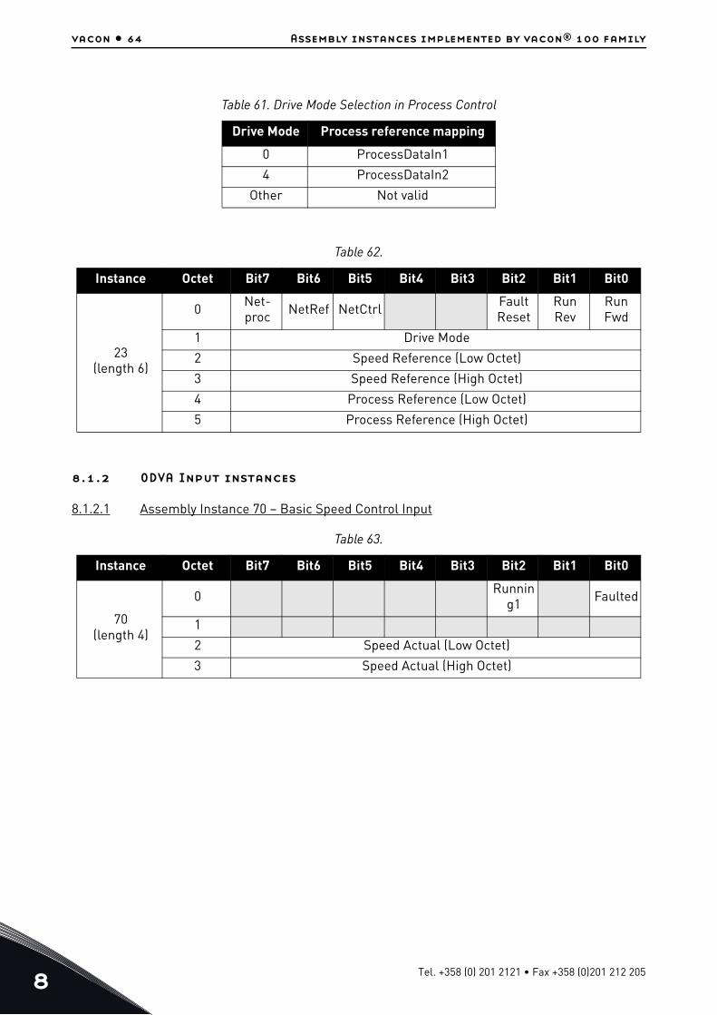
8
vacon • 64 Assembly instances implemented by vacon® 100 family
8.1.2 ODVA Input instances
8.1.2.1 Assembly Instance 70 – Basic Speed Control Input
Table 61. Drive Mode Selection in Process Control
Drive Mode Process reference mapping0 ProcessDataIn1
4 ProcessDataIn2
Other Not valid
Table 62.
Instance Octet Bit7 Bit6 Bit5 Bit4 Bit3 Bit2 Bit1 Bit0
23(length 6)
0 Net-proc NetRef NetCtrl Fault
ResetRun Rev
Run Fwd
1 Drive Mode
2 Speed Reference (Low Octet)
3 Speed Reference (High Octet)
4 Process Reference (Low Octet)
5 Process Reference (High Octet)
Table 63.
Instance Octet Bit7 Bit6 Bit5 Bit4 Bit3 Bit2 Bit1 Bit0
70(length 4)
0 Running1 Faulted
1
2 Speed Actual (Low Octet)
3 Speed Actual (High Octet)
Tel. +358 (0) 201 2121 • Fax +358 (0)201 212 205

Assembly instances implemented by vacon® 100 family vacon • 65
8.1.2.2 Assembly Instance 71 – Extended Speed Control Input
8.1.2.3 Assembly Instance 73 – Extended Speed and Torque Control Input
8.1.2.4 Assembly Instance 75 – Extended Process Control Input
Table 64.
Instance Octet Bit7 Bit6 Bit5 Bit4 Bit3 Bit2 Bit1 Bit0
71(length 4)
0 AtRef-erence
Ref-From-
Net
Ctrl-From-
NetReady
Running2
(Rev)
Running1
(Fwd)
Warn-ing Faulted
1 Drive State
2 Speed Actual (Low Octet)
3 Speed Actual (High Octet)
Table 65.
Instance Octet Bit7 Bit6 Bit5 Bit4 Bit3 Bit2 Bit1 Bit0
73(length 6)
0 AtRef-erence
Ref-From-
Net
Ctrl-From-
NetReady
Running2
(Rev)
Running1
(Fwd)
Warn-ing Faulted
1 Drive State
2 Speed Actual (Low Octet)
3 Speed Actual (High Octet)
4 Torque Actual (Low Octet)
5 Torque Actual (High Octet)
Table 66.
Instance Octet Bit7 Bit6 Bit5 Bit4 Bit3 Bit2 Bit1 Bit0
75(length 6)
0 AtRef-erence
Ref-From-
Net
Ctrl-From-
NetReady
Running2
(Rev)
Running1
(Fwd)
Warn-ing Faulted
1 Drive State
2 Speed Actual (Low Octet)
3 Speed Actual (High Octet)
4 Process Actual (Low Octet)
5 Process Actual (High Octet)
24-hour support +358 (0)201 212 575 • Email: [email protected]

8
vacon • 66 Assembly instances implemented by vacon® 100 family
8.2 Vendor-specific I/O Assembly Instances
The VACON® 100 Family AC drives support the assemblies 101, 111, 128, 131, 141, 107, 117, 127, 137 and 147.
The instances 101 and 107 use the CIP control and status words. Others use the vendor specific control and status words. All items started with “FB” are sent directly to the drive without any modifications.
8.2.1 Vendor Output Instances
8.2.1.1 Assembly Instance 101
Table 67. Vendor-specific I/O Reference Data Descriptions
Attribute Unit Range NoteFB Speed Reference % 0...10000 (100.00%)
ProcessDataIn1..8 - -
Table 68. Vendor-specific I/O Actual Data Descriptions
Attribute Unit Range NoteFB Speed Actual % 0...10000 (100.00%)
RPM Speed Actual rpm -32768…32767 Ramp output frequency converted to rpm.
Speed Actual With Slip rpm 0...32767 Slip compensated RPM value.
ProcessDataOut1..8 - -
Drive State - 0…7 See Table 32
Table 69.
Instance Octet Bit7 Bit6 Bit5 Bit4 Bit3 Bit2 Bit1 Bit0
101(length 8)
0 NetRef NetCtrl Fault Reset
Run Rev
Run Fwd
1
2 FBSpeedReference (Low Octet) in %
3 FBSpeedReference (High Octet) in %
4 FBProcessDataIn1 (Low Octet)
5 FBProcessDataIn1 (High Octet)
6 FBProcessDataIn2 (Low Octet)
7 FBProcessDataIn2 (High Octet)
Tel. +358 (0) 201 2121 • Fax +358 (0)201 212 205

Assembly instances implemented by vacon® 100 family vacon • 67
8.2.1.2 Assembly Instance 111
Table 70.
Instance Octet Bit7 Bit6 Bit5 Bit4 Bit3 Bit2 Bit1 Bit0
111(length 20)
0 FBFixedControlWord (Low Octet)
1 FBFixedControlWord (High Octet)
2 FBSpeedReference (Low Octet) in %
3 FBSpeedReference (High Octet) in %
4 FBProcessDataIn1 (Low Octet)
5 FBProcessDataIn1 (High Octet)
6 FBProcessDataIn2 (Low Octet)
7 FBProcessDataIn2 (High Octet)
8 FBProcessDataIn3 (Low Octet)
9 FBProcessDataIn3 (High Octet)
10 FBProcessDataIn4 (Low Octet)
11 FBProcessDataIn4 (High Octet)
12 FBProcessDataIn5 (Low Octet)
13 FBProcessDataIn5 (High Octet)
14 FBProcessDataIn6 (Low Octet)
15 FBProcessDataIn6 (High Octet)
16 FBProcessDataIn7 (Low Octet)
17 FBProcessDataIn7 (High Octet)
18 FBProcessDataIn8 (Low Octet)
19 FBProcessDataIn8 (High Octet)
24-hour support +358 (0)201 212 575 • Email: [email protected]

8
vacon • 68 Assembly instances implemented by vacon® 100 family
8.2.1.3 Assembly Instance 128
The contents of the assembly are otherwise identical to the output assembly 111, except that the second octet of the assembly is the high octet of FBGeneralControlWord instead of FBFixedControlWord.
Table 71.
Instance Octet Bit7 Bit6 Bit5 Bit4 Bit3 Bit2 Bit1 Bit0
128(length 20)
0 FBFixedControlWord (Low Octet)
1 FBGeneralControlWord (High Octet)
2 FBSpeedReference (Low Octet) in %
3 FBSpeedReference (High Octet) in %
4 FBProcessDataIn1 (Low Octet)
5 FBProcessDataIn1 (High Octet)
6 FBProcessDataIn2 (Low Octet)
7 FBProcessDataIn2 (High Octet)
8 FBProcessDataIn3 (Low Octet)
9 FBProcessDataIn3 (High Octet)
10 FBProcessDataIn4 (Low Octet)
11 FBProcessDataIn4 (High Octet)
12 FBProcessDataIn5 (Low Octet)
13 FBProcessDataIn5 (High Octet)
14 FBProcessDataIn6 (Low Octet)
15 FBProcessDataIn6 (High Octet)
16 FBProcessDataIn7 (Low Octet)
17 FBProcessDataIn7 (High Octet)
18 FBProcessDataIn8 (Low Octet)
19 FBProcessDataIn8 (High Octet)
Tel. +358 (0) 201 2121 • Fax +358 (0)201 212 205

Assembly instances implemented by vacon® 100 family vacon • 69
8.2.1.4 Assembly Instance 131
8.2.2 Vendor Input Instances
8.2.2.1 Assembly Instance 107
Table 72.
Instance Offset Octet 0 Octet +1 Octet +2 Octet +3
131(length 40)
0 FBFixedControl-Word (Low Octet)
FBFixedControl-Word (High
Octet)
FBGeneralCon-trolWord (Low
Octet)
FBGeneralCon-trolWord (High
Octet)
4 Reserved Reserved FBSpeedRef (Low Octet)
FBSpeedRef (High Octet)
8 FBProcessDataIn1 Bits 7:0
FBProcessDataIn1 Bits 15:8
FBProcessDataIn1 Bits 23:16
FBProcessDataIn1 Bits 31:24
12 FBProcessDataIn2 Bits 7:0
FBProcessDataIn2 Bits 15:8
FBProcessDataIn2 Bits 23:16
FBProcessDataIn2 Bits 31:24
16 FBProcessDataIn3 Bits 7:0
FBProcessDataIn3 Bits 15:8
FBProcessDataIn3 Bits 23:16
FBProcessDataIn3 Bits 31:24
20 FBProcessDataIn4 Bits 7:0
FBProcessDataIn4 Bits 15:8
FBProcessDataIn4 Bits 23:16
FBProcessDataIn4 Bits 31:24
24 FBProcessDataIn5 Bits 7:0
FBProcessDataIn5 Bits 15:8
FBProcessDataIn5 Bits 23:16
FBProcessDataIn5 Bits 31:24
28 FBProcessDataIn6 Bits 7:0
FBProcessDataIn6 Bits 15:8
FBProcessDataIn6 Bits 23:16
FBProcessDataIn6 Bits 31:24
32 FBProcessDataIn7 Bits 7:0
FBProcessDataIn7 Bits 15:8
FBProcessDataIn7 Bits 23:16
FBProcessDataIn7 Bits 31:24
36 FBProcessDataIn8 Bits 7:0
FBProcessDataIn8 Bits 15:8
FBProcessDataIn8 Bits 23:16
FBProcessDataIn8 Bits 31:24
Table 73.
Instance Octet Bit7 Bit6 Bit5 Bit4 Bit3 Bit2 Bit1 Bit0
107(length 8)
0 AtRef-erence
Ref-From-
Net
Ctrl-From-
NetReady
Running2
(Rev)
Running1
(Fwd)
Warn-ing Faulted
1 Drive State
2 FBSpeedActual (Low Octet) in %
3 FBSpeedActual (High Octet) in %
4 FBProcessDataOut1 (Low Octet)
5 FBProcessDataOut1 (High Octet)
6 FBProcessDataOut2 (Low Octet)
7 FBProcessDataOut2 (High Octet)
24-hour support +358 (0)201 212 575 • Email: [email protected]

8
vacon • 70 Assembly instances implemented by vacon® 100 family
8.2.2.2 Assembly Instance 117
Table 74.
Instance Octet Bit7 Bit6 Bit5 Bit4 Bit3 Bit2 Bit1 Bit0
117(length 34)
0 FBFixedStatusWord (Low Octet)
1 FBFixedStatusWord (High Octet)
2 FBSpeedActual (Low Octet) in %
3 FBSpeedActual (High Octet) in %
4 RPMSpeedActual (Low Octet) in rpm
5 RPMSpeedActual (High Octet) in rpm
6 RPM With Slip SpeedActual (Low Octet) in rpm
7 RPM With Slip SpeedActual (High Octet) in rpm
8 Reserved (=0)
... Reserved (=0)
17 Reserved (=0)
18 FBProcessDataOut1 (Low Octet)
19 FBProcessDataOut1 (High Octet)
20 FBProcessDataOut2 (Low Octet)
21 FBProcessDataOut2 (High Octet)
22 FBProcessDataOut3 (Low Octet)
23 FBProcessDataOut3 (High Octet)
24 FBProcessDataOut4 (Low Octet)
25 FBProcessDataOut4 (High Octet)
26 FBProcessDataOut5 (Low Octet)
27 FBProcessDataOut5 (High Octet)
28 FBProcessDataOut6 (Low Octet)
29 FBProcessDataOut6 (High Octet)
30 FBProcessDataOut7 (Low Octet)
31 FBProcessDataOut7 (High Octet)
32 FBProcessDataOut8 (Low Octet)
33 FBProcessDataOut8 (High Octet)
Tel. +358 (0) 201 2121 • Fax +358 (0)201 212 205

Assembly instances implemented by vacon® 100 family vacon • 71
8.2.2.3 Assembly Instance 127
The contents of the assembly are otherwise identical to the input assembly 117, except that the second octet of the assembly is the high octet of FBGeneralStatusWord instead of FBFixedStatusWord.
Table 75.
Instance Octet Bit7 Bit6 Bit5 Bit4 Bit3 Bit2 Bit1 Bit0
127(length 20)
0 FBFixedStatusWord (Low Octet)
1 FBGeneralStatusWord (High Octet)
2 FBSpeedActual (Low Octet) in %
3 FBSpeedActual (High Octet) in %
4 FBProcessDataOut1 (Low Octet)
5 FBProcessDataOut1 (High Octet)
6 FBProcessDataOut2 (Low Octet)
7 FBProcessDataOut2 (High Octet)
8 FBProcessDataOut3 (Low Octet)
9 FBProcessDataOut3 (High Octet)
10 FBProcessDataOut4 (Low Octet)
11 FBProcessDataOut4 (High Octet)
12 FBProcessDataOut5 (Low Octet)
13 FBProcessDataOut5 (High Octet)
14 FBProcessDataOut6 (Low Octet)
15 FBProcessDataOut6 (High Octet)
16 FBProcessDataOut7 (Low Octet)
17 FBProcessDataOut7 (High Octet)
18 FBProcessDataOut8 (Low Octet)
19 FBProcessDataOut8 (High Octet)
24-hour support +358 (0)201 212 575 • Email: [email protected]

8
vacon • 72 Assembly instances implemented by vacon® 100 family
8.2.2.4 Input Assembly Instance 137
8.3 Mapping of Standard Output Assemblies onto VACON® data
This section specifies how the data in the Standard Output Assemblies are mapped into VACON® data.
8.3.1 FBGeneralControlWord and FBGeneralStatusWord
FBGeneralControlWord and FBGeneralStatusWord are purely application specific. Check the used application’s manual for description of their content.
8.3.2 FBFixedControlWord
See Chapter 9 "APPENDIX 1 - VENDOR CONTROL AND STATUS WORD DESCRIPTIONS".
8.3.3 Start/Stop bit in VACON® FBFixedControlWord
If one of the “RunFwd” or “RunRev” bits in an Output Assembly has the value 1, the “Start/Stop” bit 0 in the VACON® FBFixedControlWord is set to 1. Otherwise the bit is set to 0.
If both the “RunFwd” and “RunRev” bits have the value 1, no changes are done to FBFixedControlWord.
Table 76.
Instance Offset Octet 0 Octet +1 Octet +2 Octet +3
137(length 40)
0FBFixedStatus-
Word (Low Octet)
FBFixedStatus-Word (High
Octet)
FBGeneralSta-tus-Word (Low
Octet)
FBGeneralSta-tus-Word (High
Octet)
4 Reserved Reserved FBSpeedActual (Low Octet)
FBSpeedActual (High Octet)
8 FBProcessDataOut1 Bits 7:0
FBProcessDataOut1 Bits 15:8
FBProcessDataOut1 Bits 23:16
FBProcessDataOut1 Bits 31:24
12 FBProcessDataOut2 Bits 7:0
FBProcessDataOut2 Bits 15:8
FBProcessDataOut2 Bits 23:16
FBProcessDataOut2 Bits 31:24
16 FBProcessDataOut3 Bits 7:0
FBProcessDataOut3 Bits 15:8
FBProcessDataOut3 Bits 23:16
FBProcessDataOut3 Bits 31:24
20 FBProcessDataOut4 Bits 7:0
FBProcessDataOut4 Bits 15:8
FBProcessDataOut4 Bits 23:16
FBProcessDataOut4 Bits 31:24
24 FBProcessDataOut5 Bits 7:0
FBProcessDataOut5 Bits 15:8
FBProcessDataOut5 Bits 23:16
FBProcessDataOut5 Bits 31:24
28 FBProcessDataOut6 Bits 7:0
FBProcessDataOut6 Bits 15:8
FBProcessDataOut6 Bits 23:16
FBProcessDataOut6 Bits 31:24
32 FBProcessDataOut7 Bits 7:0
FBProcessDataOut7 Bits 15:8
FBProcessDataOut7 Bits 23:16
FBProcessDataOut7 Bits 31:24
36 FBProcessDataOut8 Bits 7:0
FBProcessDataOut8 Bits 15:8
FBProcessDataOut8 Bits 23:16
FBProcessDataOut8 Bits 31:24
Tel. +358 (0) 201 2121 • Fax +358 (0)201 212 205

Assembly instances implemented by vacon® 100 family vacon • 73
8.3.4 Direction bit in VACON® FBFixedControlWord
If the “RunRev” bit in an Output Assembly has the value 1, and the “RunFwd” bit in the assembly has the value 0, then the “Direction” bit 1 in the VACON® FBFixedControlWord is set to 1. Otherwise the bit is set to 0.
8.3.5 Fault Reset bit in VACON® FBFixedControlWord
The “Fault Reset” bit in an Output Assembly is mapped to the “Fault Reset” bit 2 in the VACON® FBFixedControlWord. Both bits are rising-edge sensitive.
8.3.6 Request Fieldbus Control bit in VACON® FBFixedControlWord
The “NetCtrl” bit in an Output Assembly is not mapped to the “Request Fieldbus Control” bit 8 in the VACON® FBFixedControlWord because this way you can place the drive to the IO or keypad control while fieldbus is active.
8.3.7 Request Fieldbus Reference bit in VACON® FBFixedControlWord
The “NetRef” bit in an Output Assembly is not mapped to the “Request Fieldbus Reference” bit 9 in the VACON® FBFixedControlWord.
8.4 Mapping of VACON® data onto Standard Input Assemblies
This section specifies how the VACON® data is mapped onto the data in the Standard Input Assemblies.
8.4.1 FBFixedStatusWord
See Chapter 9 "APPENDIX 1 - VENDOR CONTROL AND STATUS WORD DESCRIPTIONS".
8.4.2 Ready Indication bit in VACON® FBFixedStatusWord
The “Ready Indication” bit 0 in the VACON®VACON® FBFixedStatusWord is mapped to the “Ready” bit in an Input Assembly which supports this bit.
8.4.3 Run/Stop Indication bit in VACON® FBFixedStatusWord
The “Run/Stop Indication” bit 1 in the VACON® FBFixedStatusWord is mapped to the “Running1” and “Running2” bits in an Input Assembly which supports these bits. The state of the Running1 and
24-hour support +358 (0)201 212 575 • Email: [email protected]

8
vacon • 74 Assembly instances implemented by vacon® 100 family
Running2 bits depends further on the “Direction Indication” bit 2 of the VACON® FBFixedStatusWord as follows:
8.4.4 Direction Indication bit in VACON® FBFixedStatusWord
See chapter 8.4.3.
8.4.5 Fault Indication bit in VACON® FBFixedStatusWord
The “Fault Indication” bit 3 in the VACON® FBFixedStatusWord is mapped to the “Faulted” bit in an Input Assembly which supports this bit.
8.4.6 Alarm Indication bit in VACON® FBFixedStatusWord
The “Alarm Indication” bit 4 in the VACON® FBFixedStatusWord is mapped to the “Warning” bit in an Input Assembly which supports this bit.
8.4.7 Setpoint Reached Indication bit in VACON® FBFixedStatusWord
The “Setpoint Reached Indication” bit 5 in the VACON® FBFixedStatusWord is mapped to the “AtReference” bit in an Input Assembly which supports this bit.
8.4.8 Fieldbus Control indication in Input Assemblies
The selected control place is indicated in the Input Assemblies which contain the “CtrlFromNet” bit. If the control place is assigned to fieldbus then this bit is set to 1, else it is 0.
8.4.9 Fieldbus Reference indication in Input Assemblies
The selected reference is indicated in Input Assemblies which contain the “RefFromNet” bit. If the reference is assigned to fieldbus then this bit is set to 1, otherwise it is 0.
8.4.10 FBSpeedReference in percentage
This is the reference 1 to the AC drive. The allowed scaling is from 0 to 10000. In the application, the value is scaled in percentage of the frequency area between set minimum and maximum frequency.
Table 77. Run/Stop Bit Indication Map
Run/Stop = 0 Run/Stop = 1
Direction = X Direction = 0 Direction = 1
Running1 0 1 0
Running2 0 0 1
Tel. +358 (0) 201 2121 • Fax +358 (0)201 212 205

APPENDIX 1 - VENDOR CONTROL AND STATUS WORD DESCRIPTIONS vacon • 75
9. APPENDIX 1 - VENDOR CONTROL AND STATUS
WORD DESCRIPTIONS
9.1 FBFixedControlWord and FBGeneralControlWord
The Control word is composed of 32 bits. FBFixedControlWord consist of the first 16 bits. FBGen-eralControlWord consist of the remaining 16 bits. While the functionality of FBFixedControlWord is fixed in the VACON® standard applications, the functionality of FBGeneralControlWord is totally application specific and can vary even in the VACON® standard applications.
The meanings of FBFixedControlWord bits are described below. Unused bits have to be set to zero.
NOTE! This table is valid for VACON® standard applications.
Table 78. FBFixedControlWord bits
Bit Function Description
B0 Start/Stop0 Stop request from fieldbus.
1 Run request from fieldbus.
B1 Direction0 Requested direction is "FORWARD".
1 Requested direction is "REVERSE".
B2 Fault reset0 No action.
1 No action. Rising edge (0->1) = Active faults, alarms and infos are reset.
B3 Stop mode 10 Stop mode is unmodified.
1 Stop mode is overridden to "Coasting".
B4 Stop mode 20 Stop mode is unmodified.
1 Stop mode is overridden to "Ramping".
B5 Quick ramp time0 Normal deceleration ramp time.
1 Deceleration ramp time is switched to shorter than normal.
B6 Freeze Setpoint
0Changes in the setpoint value from fieldbus (FB
Speed Reference) are taken into use by the appli-cation.
1Changes in the setpoint value from fieldbus (FB Speed Reference) are not taken into use by the
application.
B7 Setpoint to Zero0 The setpoint value from fieldbus is taken from FB
Speed Reference.
1 The setpoint value from fieldbus is changed to 0.
B8 Request Fieldbus Control
0 Control Place is as parameterized in the drive (unchanged).
1 Control Place is overridden to Fieldbus Control.
B9 Request Fieldbus Reference
0 Source of the setpoint value is as parameterized in the drive (unchanged).
1 Source of the setpoint value is overridden to Fieldbus.
24-hour support +358 (0)201 212 575 • Email: [email protected]

9
vacon • 76 APPENDIX 1 - VENDOR CONTROL AND STATUS WORD DESCRIPTIONS
9.2 FBFixedStatusWord and FBGeneralStatusWord
The Status word is composed of 32 bits. FBFixedStatusWord consist of the first 16 bits. FBGen-eralStatusWord consist of the remaining 16 bits. While the functionality of FBFixedStatusWord is fixed in the VACON® standard applications, the functionality of FBGeneralStatusWord is totally application specific and can vary even in the VACON® standard applications.
The meanings of FBFixedStatusWord bits are described below. Unused bits have to be set to zero.
B10 Jogging 10 No action.
1 Jogging request with ref1.
B11 Jogging 20 No action.
1 Jogging request with ref2.
B12 Quick stop0 Drive operates as normal.
1 Drive executes quick stop / emergency stop.
B13 Reserved0 -
1 -
B14 Reserved0 -
1 -
B15 Reserved0 -
1 -
Table 79. FBFixedStatusWord bits
Bit Function Description
B0 Ready0 Drive is not ready.
1 Drive is ready to run.
B1 Run0 Motor is not running.
1 Motor is running.
B2 Direction0 Motor is running clockwise.
1 Motor is running counterclockwise.
B3 Fault0 No fault active.
1 Drive has an active fault.
B4 Alarm0 No alarm active.
1 Drive has active alarm.
B5 At reference0 Motor is not running at reference speed.
1 Motor is running at reference speed.
B6 Zero speed0 Motor is not at zero speed.
1 Motor is running at zero speed.
B7 Flux ready0 Motor is not magnetized.
1 Motor is magnetized.
B8-B12 Reserved
Table 78. FBFixedControlWord bits
Bit Function Description
Tel. +358 (0) 201 2121 • Fax +358 (0)201 212 205

APPENDIX 2 - FIELDBUS PARAMETRISATION vacon • 77
24-hour support +358 (0)201 212 575 • Email: [email protected]
10. APPENDIX 2 - FIELDBUS PARAMETRISATION
The following chapter describes briefly how to parametrise the AC drive in order for the motor to be controllable via fieldbus. These instructions are written for basic applications. For more information, consult the application-specific manual.
In order for the AC drive to accept commands from the fieldbus network, the control place of the AC drive has to be set to fieldbus. The default value of the parameter "Control Place" is usually I/O. Note that if the control unit firmware is updated, the default settings are restored. In addition, some applications may have the remote speed reference selection set by default to other than fieldbus. In these cases, the speed reference selection must be set to fieldbus, in order for the speed reference to be controlled via fieldbus. In EtherNet/IP, the bits NetCtrl, NetRef and NetProc must be set so that the AC drive will use the sent commands/reference setpoint values. The bits Ctrl From Net and Ref From Net can be read to determine the actual control / reference place. Note that these bits are valid only if NetCtrl / NetRef bits are also set.
NOTE! The motor control mode should be selected to support the used process and profile.
10.1 Fieldbus control and basic reference selection
The following tables list some of the parameters related to fieldbus control in applications for use via fieldbus. See the application specific manuals for more detailed information.
Parameters can be read and written by using the drive panel, PC Tools or fieldbus protocol (see Chapter 7.3.1).
10.2 Torque control parametrization
Some extra parametrisation has to be made in order to control the frequency control with torque control. The following instructions are for the VACON® 100 INDUSTRIAL, see the application-specific manual for more detailed information.
• Motor control mode (ID 600) should be configured to "Torque control" (2).
To configure the drive to use correct torque reference, select the parameter "Torque Reference Selection" to ProcessDataIn1 (9). This can be done with:
- PC-tool or panel (VACON® 100 Family AC drives: P 3.3.2.1) / ID 641- Vendor Parameter Object
Table 80. Parametrization for VACON® 100 INDUSTRIAL
Parameter name ID Value Default Panel Tree
Control mode 6000 = Frequency1 = Speed2 = Torque
0 P 3.1.2.1
Remote control place 172 1 = Fieldbus CTRL 0 P 3.2.1
Local / remote 211 0 = Remote 0 P 3.2.2
Fieldbus ref. sel. 122 3 = Fieldbus 3 P 3.3.1.10

APPENDIX 3 - LWIP LICENCE vacon • 78
24-hour support +358 (0)201 212 575 • Email: [email protected]
11. APPENDIX 3 - LWIP LICENCE
License for LWIP
Copyright (c) 2001, 2002 Swedish Institute of Computer Science.
All rights reserved.
Redistribution and use in source and binary forms, with or without modification, are permitted provided that the following conditions are met:
1.Redistributions of source code must retain the above copyright notice, this list of conditions and the following disclaimer.
2.Redistributions in binary form must reproduce the above copyright notice, this list of conditions and the following disclaimer in the documentation and/or other materials provided with the distri-bution.
3.The name of the author may not be used to endorse or promote products derived from this soft-ware without specific prior written permission.
THIS SOFTWARE IS PROVIDED BY THE AUTHOR “AS IS” AND ANY EXPRESS OR IMPLIED WARRANTIES, INCLUDING, BUT NOT LIMITED TO, THE IMPLIED WARRANTIES OF MERCHANTABILITY AND FITNESS FOR A PARTICULAR PURPOSE ARE DISCLAIMED. IN NO EVENT SHALL THE AUTHOR BE LIABLE FOR ANY DIRECT, INDIRECT, INCIDENTAL, SPECIAL, EXEMPLARY, OR CONSEQUENTIAL DAMAGES (INCLUDING, BUT NOT LIMITED TO, PROCUREMENT OF SUBSTITUTE GOODS OR SERVICES; LOSS OF USE, DATA, OR PROFITS; OR BUSINESS INTERRUPTION) HOWEVER CAUSED AND ON ANY THEORY OF LIABILITY, WHETHER IN CONTRACT, STRICT LIABILITY, OR TORT (INCLUDING NEGLIGENCE OR OTHERWISE) ARISING IN ANY WAY OUT OF THE USE OF THIS SOFTWARE, EVEN IF ADVISED OF THE POSSIBILITY OF SUCH DAMAGE.

Document ID:
DPD01045DRev. D
Sales code: DOC-100ETHERIP+DLUK
Vacon LtdMember of the Danfoss GroupRunsorintie 765380 VaasaFinland
www.danfoss.com