vacon 20 ac drives - motkonsis | frekans konvertörü · 4.1commissioning steps of vacon 20 45...
TRANSCRIPT

vacon 20ac drives
pfc application manual
®

Table of contents
Document: DPD01436B Release date: Feb. 2014
1.Safety 11.1Warnings 11.2Safety instructions 31.3Earthing and earth fault protection 31.4Before running the motor 5
2.Receipt of delivery 62.1Type designation code 62.2Storage 62.3Maintenance 7
2.3.1Capacitor recharge 72.4Warranty 82.5Manufacturer’s declaration of conformity 9
3.Installation 103.1Mechanical installation 10
3.1.1Vacon 20 dimensions 143.1.2Cooling 183.1.3Power losses 193.1.4EMC levels 263.1.5Changing the EMC protection class from C2 or C3 to C4 27
3.2Cabling and connections 293.2.1Power cabling 293.2.2Control cabling 313.2.3Allowed option boards in Vacon20 353.2.4Screw of cables 373.2.5Cable and fuse specifications 393.2.6General cabling rules 423.2.7Stripping lengths of motor and mains cables 433.2.8Cable installation and the UL standards 433.2.9Cable and motor insulation checks 43
4.Commissioning 454.1Commissioning steps of Vacon 20 45
5.Fault tracing 476.PFC SYSTEM Interface 51
6.1I/O signals 517.Control panel 56
7.1General 567.2Display 567.3Keypad 577.4Navigation on the Vacon 20 control panel 59
Application: ACCN1051V100
1
1
7.4.1Main menu 597.4.2Reference menu 607.4.3Monitoring menu 617.4.4Parameter menu 627.4.5System menu 64
8.PFC application parameters 668.1Startup wizard 678.2Monitor 67
8.2.1Basic 678.2.2I/O 688.2.3Extras/advanced 698.2.4PID control 69
8.3Main parameters lists (Menu PAR) 708.3.1Motor settings 708.3.2Start/stop setup 728.3.3References 738.3.4Ramps and brakes 738.3.5Digital inputs 758.3.6Analog inputs 768.3.7Digital outputs 778.3.8Analog outputs 788.3.9Fieldbus data-Mapping 798.3.10Prohibited frequencies 798.3.11Protections 808.3.12Automatic reset 828.3.13PID controller 828.3.14PFC 848.3.15Application settings 85
8.4System parameters 859.Parameter descriptions 89
9.1Motor settings 899.2Start/stop setup 939.3References 959.4Ramps and brakes 969.5Digital inputs 989.6Analog inputs 999.7Digital outputs 1009.8Analog outputs 1019.9Fieldbus data-mapping 1029.10Prohibited frequencies 1039.11Protections 104
9.12Automatic reset 1079.13PID controller 1089.14PFC 1109.15Application setting 113
10.Technical data 11410.1Vacon 20 technical data 11410.2Power ratings 117
10.2.1Vacon 20 – Mains voltage 208-240 V 11710.2.2Vacon 20 – Mains voltage 115 V 11810.2.3Vacon 20 – Mains voltage 380-480 V 11810.2.4Vacon 20 – Mains voltage 600 V 119
10.3Brake resistors 119
1

safety vacon • 1
1. SAFETYONLY A COMPETENT ELECTRICIAN IS ALLOWED TO CARRY OUT THE ELECTRICAL INSTALLATION!
This manual contains clearly marked cautions and warnings which are intended for your personal safety and to avoid any unintentional damage to the product or con-nected appliances.Please read the information included in cautions and warnings carefully:
1.1 Warnings
=Dangerous voltageRisk of death or severe injury
=General warningRisk of damage to the product or connected appliances
The components of the power unit of the frequency converter are live when Vacon 20 is connected to mains. Coming into contact with this voltage is extremely dangerous and may cause death or severe injury. The control unit is isolated from the mains potential.
The motor terminals U, V, W (T1, T2, T3) and the possible brake resistor terminals - / + are live when Vacon 20 is connected to mains, even if the motor is not running.
The control I / O-terminals are isolated from the mains poten-tial. However, the relay output terminals may have a danger-ous control voltage present even when Vacon 20 is disconnected from mains.
The earth leakage current of Vacon 20 frequency converters exceeds 3.5 mA AC. According to standard EN61800-5-1, a reinforced protective ground connection must be ensured.
If the frequency converter is used as a part of a machine, the machine manufacturer is responsible for providing the machine with a main switch (EN 60204-1).
If Vacon 20 is disconnected from mains while running the motor, it remains live if the motor is energized by the process. In this case the motor functions as a generator feeding energy to the frequency converter.
24-hour support +358 (0)201 212 575 • Email: [email protected]
1

2 • vacon safety
1
After disconnecting the frequency converter from the mains, wait until the fan stops and the indicators on the display go out. Wait 5 more minutes before doing any work on Vacon 20 connections.
The motor can start automatically after a fault situation, if the autoreset function has been activated.
Tel. +358 (0)201 2121 • Fax +358 (0)201 212205

safety vacon • 3
1.2 Safety instructions
The Vacon 20 frequency converter has been designed for fixed installations only.
Do not perform any measurements when the frequency con-verter is connected to the mains.
Do not perform any voltage withstand tests on any part of Vacon 20. The product safety is fully tested at factory.
Prior to measurements on the motor or the motor cable, dis-connect the motor cable from the frequency converter.
Do not open the cover of Vacon 20. Static voltage discharge from your fingers may damage the components. Opening the cover may also damage the device. If the cover of Vacon 20 is opened, warranty becomes void.
1.3 Earthing and earth fault protectionThe Vacon 20 frequency converter must always be earthed with an earthing conduc-tor connected to the earthing terminal. See figure below:
MI1 - MI3
24-hour support +358 (0)201 212 575 • Email: [email protected]
1
4 • vacon safety
1
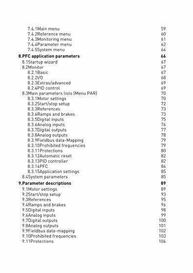
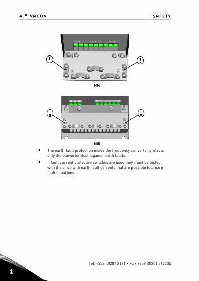
MI4
MI5
• The earth fault protection inside the frequency converter protects only the converter itself against earth faults.
• If fault current protective switches are used they must be tested with the drive with earth fault currents that are possible to arise in fault situations.
Tel. +358 (0)201 2121 • Fax +358 (0)201 212205

safety vacon • 5
1.4 Before running the motor
Checklist:
Before starting the motor, check that the motor is mounted properly and ensure that the machine connected to the motor allows the motor to be started.
Set the maximum motor speed (frequency) according to the motor and the machine connected to it.
Before reversing the motor shaft rotation direction make sure that this can be done safely.
Make sure that no power correction capacitors are connected to the motor cable.
NOTE! You can download the English and French product manuals with applica-ble safety, warning and caution information from www.vacon.com/downloads.
REMARQUE Vous pouvez télécharger les versions anglaise et française des ma-nuels produit contenant l’ensemble des informations de sécurité, avertisse-ments et mises en garde applicables sur le site www.vacon.com/downloads.
24-hour support +358 (0)201 212 575 • Email: [email protected]
1

6 • vacon receipt of delivery
2
2. RECEIPT OF DELIVERY
After unpacking the product, check that no signs of transport damages are to be found on the product and that the delivery is complete (compare the type designation of the product to the code below).
Should the drive have been damaged during the shipping, please contact primarily the cargo insurance company or the carrier.
If the delivery does not correspond to your order, contact the supplier immediately.
2.1 Type designation code
Figure 2.1: Vacon 20 type designation code
2.2 Storage
If the frequency converter is to be kept in store before use make sure that the ambi-ent conditions are acceptable:
Storing temperature -40…+70 °C
Relative humidity < 95%, no condensation
VACON0020- 1L- 0001- 1 +OPTIONS
Vacon 20
1L = Single phase3L = Three phases
1 =115V2 = 208 - 230V4 = 380 - 480V7 = 600V
Output Current
Input Voltage
+OptionsEMC2QPESQFLG
+DLNL = Dutch+DLNO = Norwegian+DLPT = Portuguese+DLRU = Russian+DLSE = Swedish+DLTR = Turkish+DLUS = US Englishempty = English
Language of the documentation+DLCN = Chinese+DLCZ = Czech+DLDE = German+DLDK = Danish+DLES = Spanish+DLFI = Finnish+DLFR = French+DLIT = Italian
Input phase
Tel. +358 (0)201 2121 • Fax +358 (0)201 212205

receipt of delivery vacon • 7
2.3 Maintenance
In normal operating conditions, Vacon 20 frequency converters are maintenance-free. However, regular maintenance is recommended to ensure a trouble-free oper-ating and a long lifetime of the drive. We recommended to follow the table below for maintenance intervals.
2.3.1 Capacitor recharge
After a longer storage time the capacitors need to be recharge in order to avoid ca-pacitor damage. Possible high leakage current through the capacitors must be lim-ited. The best way to achieve this is to use a DC-power supply with adjustable current limit.
1) Set the current limit to 300…800 mA according to the size of the drive.
2) Then connect the DC-power supply to the input phase L1 and L2.
3) Then set the DC-voltage to the nominal DC-voltage level of the (1.35*Un AC) and supply the converter for at least 1 h.
If DC-voltage is not available and the unit has been stored much longer than 12 months deenergized, consult the factory before connecting power.
Maintenance interval Maintenance action
Whenever necessary • Clean headsink*
Regular • Check tightening torques of terminals
12 months (If stored)
• Check input and output terminals and con-trol I / O terminals.
• Clean cooling tunnel.*• Check operation of cooling fan, check for
corrosion on terminals, busbars and other surfaces.*
6 - 24 months (depending on environment)• Check and clean and clean cooling fans: Main fan* Interminal fan*
* Only for frame 4 and frame 5
24-hour support +358 (0)201 212 575 • Email: [email protected]
2
8 • vacon receipt of delivery
2
2.4 Warranty
Only manufacturing defects are covered by the warranty. The manufacturer as-sumes no responsibility for damages caused during or resulting from transport, re-ceipt of the delivery, installation, commissioning or use.
The manufacturer shall in no event and under no circumstances be held responsible for damages and failures resulting from misuse, wrong installation, unacceptable ambient temperature, dust, corrosive substances or operation outside the rated specifications. Neither can the manufacturer be held responsible for consequential damages.
The Manufacturer's time of warranty is 18 months from the delivery or 12 months from the commissioning whichever expires first (Vacon Warranty Terms).
The local distributor may grant a warranty time different from the above. This war-ranty time shall be specified in the distributor's sales and warranty terms. Vacon as-sumes no responsibility for any other warranties than that granted by Vacon itself.
In all matters concerning the warranty, please contact first your distributor.
Tel. +358 (0)201 2121 • Fax +358 (0)201 212205
receipt of delivery vacon • 9
2.5 Manufacturer’s declaration of conformity
EC DECLARATION OF CONFORMITYWe
Manufacturer's name: Vacon Oyj
Manufacturer's address: P.O.Box 257eitnirosnuR
asaaV18356-NIFdnalniF
hereby declare that the product
Product name: Vacon 20 Frequency Converter
Model designation: Vacon 20 1L 0001 2…to 0009 228300ot…21000L302nocaV48300ot…41000L302nocaV
has been designed and manufactured in accordance with the followingstandards:
Safety: EN 60204 -1:2009 (as re levant),EN 61800-5-1:2007
EMC: EN 61800-3:2004+A1:2012
and conforms to t he relevant safety provisions of the Low Voltage Directive2006/95/EC and EMC Directive 2004/108/EC.
It is ensured through internal measures and quality control t hat the productconforms at all times to the requirements of the current Directive and therelevant standards.
In Vaasa, 16th of April, 2014isiaLaseV
tnediserP
The year the CE marking was affixed: 2011
24-hour support +358 (0)201 212 575 • Email: [email protected]
2

10 • vacon installation
3
3. INSTALLATION
3.1 Mechanical installation
There are two possible ways to mount Vacon 20 in the wall. For MI1-MI3, either screw or DIN-rail mounting; For MI4-MI5, screw or flange mounting.
Figure 3.1: Screw mounting, MI1 - MI3
Figure 3.2: Screw mounting, MI4 - MI5
Note! See the mounting dimensions on the back of the drive. More details in Chapter 3.1.1.
=M5
MI3
MI1
=M4
MI2
=M5
LOCREM
BACKRESET
OK
LOCREM
BACKRESET
OK
LOCREM
BACKRESET
OK
MI4=M 6
=M 6
MI5
LOCREM
BACKRESET
OK
LOCREM
BACKRESET
OK
Tel. +358 (0)201 2121 • Fax +358 (0)201 212205
installation vacon • 11
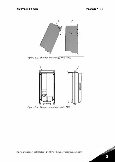
Figure 3.3: DIN-rail mounting, MI1 - MI3
Figure 3.4: Flange mounting, MI4 - MI5
1 2
LOCREM
BACKRESET
OK
24-hour support +358 (0)201 212 575 • Email: [email protected]
3

12 • vacon installation
3
Figure 3.5: Flange mounting cutout dimensions for MI4 (Unit: mm)
Figure 3.6: Flange mounting cutout dimensions for MI5 (Unit: mm)
Tel. +358 (0)201 2121 • Fax +358 (0)201 212205
installation vacon • 13
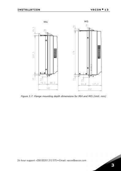
Figure 3.7: Flange mounting depth dimensions for MI4 and MI5 (Unit: mm)
MI5MI4
24-hour support +358 (0)201 212 575 • Email: [email protected]
3

14 • vacon installation
3
3.1.1 Vacon 20 dimensions
Figure 3.8: Vacon 20 dimensions, MI1 - MI3
Figure 3.9: Vacon 20 dimensions, MI4 - MI5
W2W3
W (W1)
H (
H1
)
H2
H3
D2
D (D1)
W2W3
H (
H1
)
W (W1) D (D1)
H3
H2
Tel. +358 (0)201 2121 • Fax +358 (0)201 212205

installation vacon • 15
Type H1 H2 H3 W1 W2 W3 D1 D2
MI1 160.1 147 137.3 65.5 37.8 4.5 98.5 7
MI2 195 183 170 90 62.5 5.5 101.5 7
MI3 254.3 244 229.3 100 75 5.5 108.5 7
MI4 370 350.5 336.5 165 140 7 165 -
MI5 414 398 383 165 140 7 202 -Table 3.1: Vacon 20 dimensions in millimetres
Frame Dimensions(mm) Weight*
W H D (kg.)
MI1 66 160 98 0.5
MI2 90 195 102 0.7
MI3 100 254.3 109 1
MI4 165 370 165 8
MI5 165 414 202 10
*without shipping packageTable 3.2: Vacon 20 frame dimensions (mm) and weights (kg)
Frame Dimensions(Inches) Weight*
W H D (Ibs.)
MI1 2.6 6.3 3.9 1.2
MI2 3.5 9.9 4 1.5
MI3 3.9 10 4.3 2.2
MI4 6.5 14.6 6.5 18
MI5 6.5 16.3 8 22
*without shipping packageTable 3.3: Vacon 20 frame dimensions (Inch) and weights (Ibs)
24-hour support +358 (0)201 212 575 • Email: [email protected]
3
16 • vacon installation
3
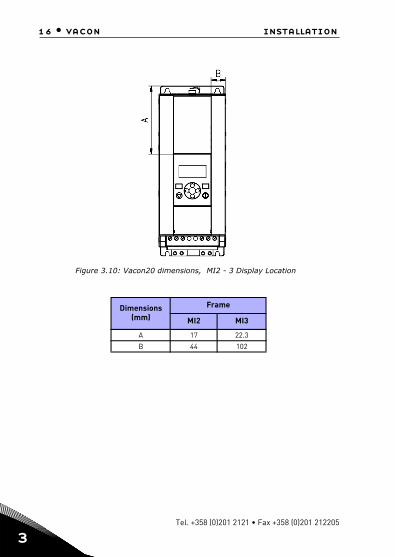
Figure 3.10: Vacon20 dimensions, MI2 - 3 Display Location
Dimensions(mm)
Frame
MI2 MI3
A 17 22.3
B 44 102
Tel. +358 (0)201 2121 • Fax +358 (0)201 212205

installation vacon • 17
Figure 3.11: Vacon20 dimensions, MI4 - 5 Display Location
Dimensions(mm)
Frame
MI2 MI3
A 205 248.5
B 87 87
24-hour support +358 (0)201 212 575 • Email: [email protected]
3
18 • vacon installation
3
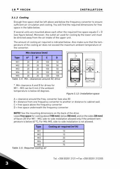
3.1.2 Cooling
Enough free space shall be left above and below the frequency converter to ensure sufficient air circulation and cooling. You will find the required dimensions for free space in the table below.
If several units are mounted above each other the required free space equals C + D (see figure below). Moreover, the outlet air used for cooling by the lower unit must be directed away from the air intake of the upper unit.
The amount of cooling air required is indicated below. Also make sure that the tem-perature of the cooling air does not exceed the maximum ambient temperature of the converter.
*. Min clearance A and B for drives for MI1 ~ MI3 can be 0 mm if the ambient temperature is below 40 degrees.
Figure 3.12: Installation space
A = clearance around the freq. converter (see also B) B = distance from one frequency converter to another or distance to cabinet wall C = free space above the frequency converterD = free space underneath the frequency converter
NOTE! See the mounting dimensions on the back of the drive. Leave free space for cooling above (100 mm), below (50 mm), and on the sides (20 mm) of Vacon 20! (For MI1 - MI3, side-to-side installation allowed only if the ambient tem-perature is below 40 °C; For MI4-MI5, side-to-side installation is not allowed.
Min clearance (mm)
Type A* B* C D
MI1 20 20 100 50
MI2 20 20 100 50
MI3 20 20 100 50
MI4 20 20 100 100
MI5 20 20 120 100Table 3.4: Min. clearances around AC drive
Type Cooling air required (m³/h)
MI1 10
MI2 10
MI3 30
MI4 45
MI5 75Table 3.5: Required cooling air
B
C
BA
D
A
Tel. +358 (0)201 2121 • Fax +358 (0)201 212205

installation vacon • 19
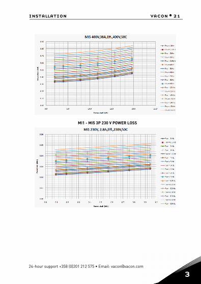
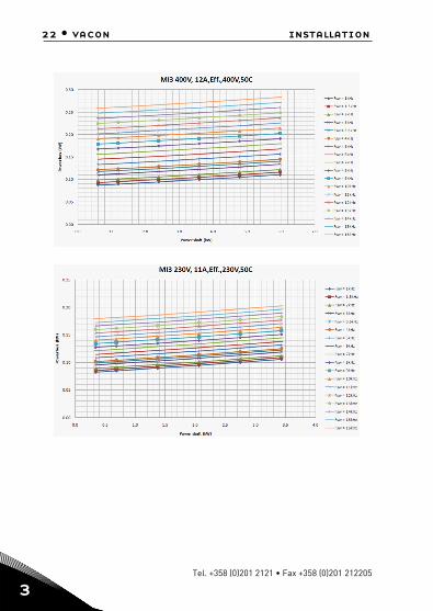
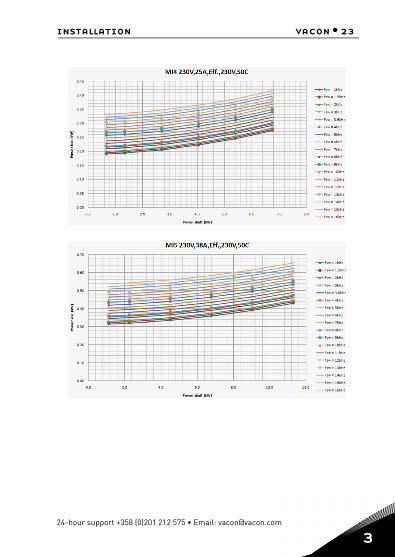
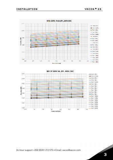
3.1.3 Power losses
If the operator wants to raise the switching frequency of the drive for some reason (typically e.g. in order to reduce the motor noise), this inevitably affects the power losses and cooling requirements, for different motor shaft power, operator can se-lect the switching frequency according to the graphs below.
MI1 - MI5 3P 380 V POWER LOSS
24-hour support +358 (0)201 212 575 • Email: [email protected]
3

20 • vacon installation
3
Tel. +358 (0)201 2121 • Fax +358 (0)201 212205
installation vacon • 21
MI1 - MI5 3P 230 V POWER LOSS
24-hour support +358 (0)201 212 575 • Email: [email protected]
3
22 • vacon installation
3
Tel. +358 (0)201 2121 • Fax +358 (0)201 212205

24 • vacon installation
3
MI1 - MI3 1P 230 V POWER LOSS
Tel. +358 (0)201 2121 • Fax +358 (0)201 212205

26 • vacon installation
3
3.1.4 EMC levels
EN61800-3 defines the division of frequency converters into four classes according to the level of electromagnetic disturbances emitted, the requirements of a power system network and the installation environment (see below). The EMC class of each product is defined in the type designation code.
Category C1: Frequency converters of this class comply with the requirements of category C1 of the product standard EN 61800-3 (2004). Category C1 ensures the best EMC characteristics and it includes converters the rated voltage of which is less than 1000 V and which are intended for use in the 1st environment.NOTE: The requirements of class C are fulfilled only as far as the conducted emis-sions are concerned.
Category C2: Frequency converters of this class comply with the requirements of category C2 of the product standard EN 61800-3 (2004). Category C2 includes con-verters in fixed installations and the rated voltage of which is less than 1000 V. The class C2 frequency converters can be used both in the 1st and the 2nd environment.
Category C3: Frequency converters of this class comply with the requirements of category C3 of the product standard EN 61800-3 (2004). Category C3 includes con-verters the rated voltage of which is less than 1000 V and which are intended for use in the second environment only.
Category C4: The drives of this class do not provide EMC emission protection. These kinds of drives are mounted in enclosures.
Environments in product standard EN 61800-3 (2004)
First environment: Environment that includes domestic premises. It also includes establishments directly connected without intermediate transformers to a low-volt-age power supply network which supplies buildings used for domestic purposes.
NOTE: houses, apartments, commercial premises or offices in a residential building are examples of first environment locations.
Second environment: Environment that includes all establishments other than those directly connected to a low-voltage power supply network which supplies buildings used for domestic purposes.NOTE: industrial areas, technical areas of any building fed from a dedicated trans-former are examples of second environment locations.
Tel. +358 (0)201 2121 • Fax +358 (0)201 212205

installation vacon • 27
3.1.5 Changing the EMC protection class from C2 or C3 to C4
The EMC protection class of MI1-3 frequency converters can be changed from class C2 or C3 to class C4 by removing the EMC-capacitor disconnecting screw, see fig-ure below. MI4 & 5 can also be changed by removing the EMC jumpers.
Note! Do not attempt to change the EMC level back to class C2 or C3. Even if the pro-cedure above is reversed, the frequency converter will no longer fulfil the EMC re-quirements of class C2 / C3!
Figure 3.13: EMC protection class, MI1 - MI3
Figure 3.14: EMC protection class, MI4
24-hour support +358 (0)201 212 575 • Email: [email protected]
3
28 • vacon installation
3
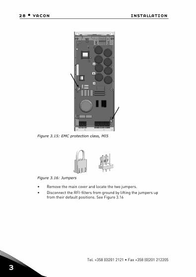
Figure 3.15: EMC protection class, MI5
Figure 3.16: Jumpers
• Remove the main cover and locate the two jumpers.• Disconnect the RFI-filters from ground by lifting the jumpers up
from their default positions. See Figure 3.16
Tel. +358 (0)201 2121 • Fax +358 (0)201 212205

installation vacon • 29
3.2 Cabling and connections
3.2.1 Power cabling
Note! Tightening torque for power cables is 0.5 - 0.6 Nm (4-5 in.lbs).
Figure 3.17: Vacon 20 power connections, MI1
Figure 3.18: Vacon 20 power connections, MI2 - MI3
1~ (230V)
3~ (230V, 400V)
Motor out
MAINS MOTOR
Strip theplastic cablecoating for360° earthing
L1 L2/N L3 U/T1 V/T2 W/T3R+ R-
1~ (230V)
3~(230V, 400V,600V)
1~ (115V)
MAINS MOTORBRAKERESISTOR
External brake resistor
Motor out
Strip theplasticcablecoatingfor 360°earthing
3~(230V, 400V,600V)
24-hour support +358 (0)201 212 575 • Email: [email protected]
3

30 • vacon installation
3
Figure 3.19: Vacon 20 power connections, MI4
Figure 3.20: Vacon 20 power connections, MI5
MAINS MOTOR
Motor out
BrakeRESISTOR
3~ (380, 480V)
MAINS MOTOR
Motor out
BrakeRESISTOR
3~ (380, 480V)
Tel. +358 (0)201 2121 • Fax +358 (0)201 212205

installation vacon • 31
3.2.2 Control cabling
Figure 3.21: Mount the PE-plate and API cable support, MI1 - MI3
Attach this plateBEFORE installingthe power cables
Attach the supportAFTER installingthe power cables
24-hour support +358 (0)201 212 575 • Email: [email protected]
3
32 • vacon installation
3
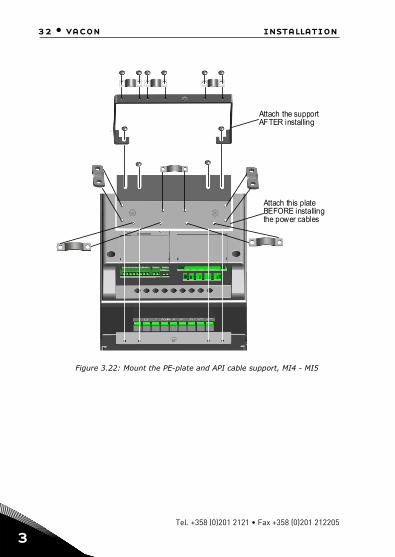
Figure 3.22: Mount the PE-plate and API cable support, MI4 - MI5
Attach the supportAFTER installing
Attach this plateBEFORE installingthe power cables
Tel. +358 (0)201 2121 • Fax +358 (0)201 212205

installation vacon • 33
Figure 3.23: Open the lid, MI1 - MI3
Figure 3.24: Open the lid, MI4 - MI5
24-hour support +358 (0)201 212 575 • Email: [email protected]
3
34 • vacon installation
3
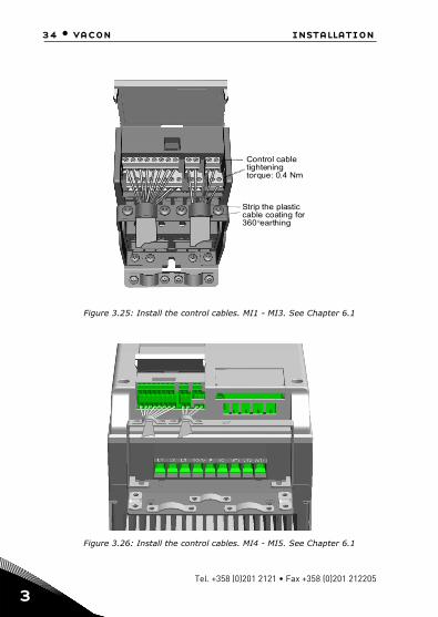
Figure 3.25: Install the control cables. MI1 - MI3. See Chapter 6.1
Figure 3.26: Install the control cables. MI4 - MI5. See Chapter 6.1
Strip the plasticcable coating for360°earthing
Control cabletighteningtorque: 0.4 Nm
Tel. +358 (0)201 2121 • Fax +358 (0)201 212205

installation vacon • 35
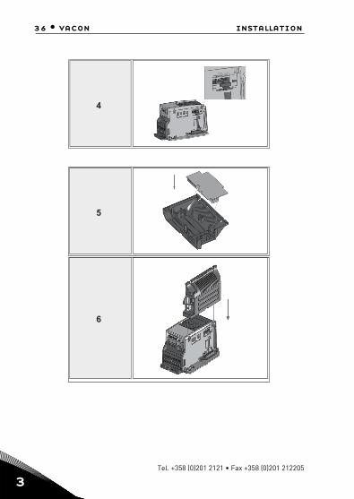
3.2.3 Allowed option boards in Vacon20
See below for the allowed option boards in the slot:
Note! OPT-B1 and OPT-B4 only support external power supply.
Option board assembly structure:
1
2
3
24-hour support +358 (0)201 212 575 • Email: [email protected]
3
36 • vacon installation
3
4
5
6
Tel. +358 (0)201 2121 • Fax +358 (0)201 212205

installation vacon • 37
3.2.4 Screw of cables
Figure 3.27: MI1 screws
Figure 3.28: MI2 screws
M4*8 Screws 12pcs
M4*8 Screws 10pcs
24-hour support +358 (0)201 212 575 • Email: [email protected]
3

38 • vacon installation
3
Figure 3.29: MI3 screws
Figure 3.30: MI4 - MI5 screw
M4*8 Screws 10pcs
M4*10 Screws 4pcs
M4*17 Screws 6pcs
M4*9 Screws 14pcs
Tel. +358 (0)201 2121 • Fax +358 (0)201 212205
installation vacon • 39
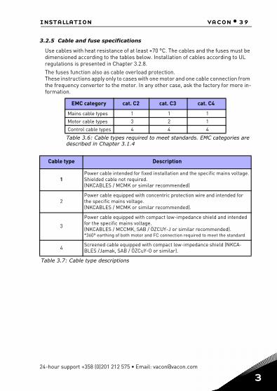
3.2.5 Cable and fuse specifications
Use cables with heat resistance of at least +70 °C. The cables and the fuses must be dimensioned according to the tables below. Installation of cables according to UL regulations is presented in Chapter 3.2.8.The fuses function also as cable overload protection.These instructions apply only to cases with one motor and one cable connection from the frequency converter to the motor. In any other case, ask the factory for more in-formation.
EMC category cat. C2 cat. C3 cat. C4
Mains cable types 1 1 1
Motor cable types 3 2 1
Control cable types 4 4 4
Table 3.6: Cable types required to meet standards. EMC categories are described in Chapter 3.1.4
Cable type Description
1Power cable intended for fixed installation and the specific mains voltage. Shielded cable not required.(NKCABLES / MCMK or similar recommended)
2Power cable equipped with concentric protection wire and intended for the specific mains voltage.(NKCABLES / MCMK or similar recommended).
3
Power cable equipped with compact low-impedance shield and intended for the specific mains voltage.(NKCABLES / MCCMK, SAB / ÖZCUY-J or similar recommended).*360º earthing of both motor and FC connection required to meet the standard
4 Screened cable equipped with compact low-impedance shield (NKCA-BLES /Jamak, SAB / ÖZCuY-O or similar).
Table 3.7: Cable type descriptions
24-hour support +358 (0)201 212 575 • Email: [email protected]
3

40 • vacon installation
3
Frame Type Fuse[A]
Mains cable
Cu [mm2]
Motor cable
Cu [mm2]
Terminal cable size (min/max)
Main terminal
[mm2]
Earth terminal
[mm2]
Control terminal
[mm2]
Relay terminal
[mm2]
MI2 0001-0004 20 2*2.5+2.5 3*1.5+1.5 1.5-4 1.5-4 0.5-1.5 0.5-1.5
MI3 0005 32 2*6+6 3*1.5+1.5 1.5-4 1.5-4 0.5-1.5 0.5-1.5Table 3.8: Cable and fuse sizes for Vacon 20, 115 V, 1~
Frame Type Fuse[A]
Mains cable
Cu [mm2]
Motor cable
Cu [mm2]
Terminal cable size (min/max)
Main terminal
[mm2]
Earth terminal
[mm2]
Control terminal
[mm2]
Relay terminal
[mm2]
MI1 0001-0003 10 2*1.5+1.5 3*1.5+1.5 1.5-4 1.5-4 0.5-1.5 0.5-1.5
MI2 0004-0007 20 2*2.5+2.5 3*1.5+1.5 1.5-4 1.5-4 0.5-1.5 0.5-1.5
MI3 0009 32 2*6+6 3*1.5+1.5 1.5-6 1.5-6 0.5-1.5 0.5-1.5Table 3.9: Cable and fuse sizes for Vacon 20, 208 - 240 V, 1~
Frame Type Fuse[A]
Mains cable
Cu [mm2]
Motor cable
Cu [mm2]
Terminal cable size (min/max)
Main terminal
[mm2]
Earth terminal
[mm2]
Control terminal
[mm2]
Relay terminal
[mm2]
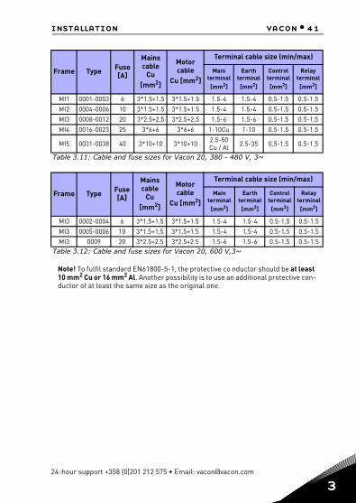
MI1 0001-0003 6 3*1.5+1.5 3*1.5+1.5 1.5-4 1.5-4 0.5-1.5 0.5-1.5
MI2 0004-0007 10 3*1.5+1.5 3*1.5+1.5 1.5-4 1.5-4 0.5-1.5 0.5-1.5
MI3 0011 20 3*2.5+2.5 3*2.5+2.5 1.5-6 1.5-6 0.5-1.5 0.5-1.5
MI4 0012-0025202540
3*6+6 3*6+6 1-10Cu 1-10 0.5-1.5 0.5-1.5
MI5 0031-0038 40 3*10+10 3*10+10 2.5-50Cu / Al 2.5-35 0.5-1.5 0.5-1.5
Table 3.10: Cable and fuse sizes for Vacon 20, 208 - 240 V, 3~
Tel. +358 (0)201 2121 • Fax +358 (0)201 212205
installation vacon • 41
Note! To fulfil standard EN61800-5-1, the protective co nductor should be at least 10 mm2 Cu or 16 mm2 Al. Another possibility is to use an additional protective con-ductor of at least the same size as the original one.
Frame Type Fuse[A]
Mains cable
Cu [mm2]
Motor cable
Cu [mm2]
Terminal cable size (min/max)
Main terminal
[mm2]
Earth terminal
[mm2]
Control terminal
[mm2]
Relay terminal
[mm2]
MI1 0001-0003 6 3*1.5+1.5 3*1.5+1.5 1.5-4 1.5-4 0.5-1.5 0.5-1.5
MI2 0004-0006 10 3*1.5+1.5 3*1.5+1.5 1.5-4 1.5-4 0.5-1.5 0.5-1.5
MI3 0008-0012 20 3*2.5+2.5 3*2.5+2.5 1.5-6 1.5-6 0.5-1.5 0.5-1.5
MI4 0016-0023 25 3*6+6 3*6+6 1-10Cu 1-10 0.5-1.5 0.5-1.5
MI5 0031-0038 40 3*10+10 3*10+10 2.5-50 Cu / Al 2.5-35 0.5-1.5 0.5-1.5
Table 3.11: Cable and fuse sizes for Vacon 20, 380 - 480 V, 3~
Frame Type Fuse[A]
Mains cable
Cu [mm2]
Motor cable
Cu [mm2]
Terminal cable size (min/max)
Main terminal
[mm2]
Earth terminal
[mm2]
Control terminal
[mm2]
Relay terminal
[mm2]
MI3 0002-0004 6 3*1.5+1.5 3*1.5+1.5 1.5-4 1.5-4 0.5-1.5 0.5-1.5
MI3 0005-0006 10 3*1.5+1.5 3*1.5+1.5 1.5-4 1.5-4 0.5-1.5 0.5-1.5
MI3 0009 20 3*2.5+2.5 3*2.5+2.5 1.5-6 1.5-6 0.5-1.5 0.5-1.5Table 3.12: Cable and fuse sizes for Vacon 20, 600 V,3~
24-hour support +358 (0)201 212 575 • Email: [email protected]
3

42 • vacon installation
3
3.2.6 General cabling rules
1 Before starting the installation, check that none of the components of the fre-quency converter is live.
2
Place the motor cables sufficiently far from other cables:• Avoid placing the motor cables in long parallel lines with other cables.• If the motor cable runs in parallel with other cables, the minimum distance
between the motor cable and other cables is 0.3 m.• The given distance also applies between the motor cables and signal cables
of other systems.• The maximum length of the motor cables for MI1-3 is 30 m. For MI4 & 5,
maximum length is 50 m, if use longer cable, current accuracy will be decreased.
• The motor cables should cross other cables at an angle of 90 degrees.
3 If cable insulation checks are needed, see Chapter 3.2.9.
4
Connecting the cables:• Strip the motor and mains cables as advised in Figure 3.31.• Connect the mains, motor and control cables into their respective termi-
nals, see Figures 3.17 - 3.26.• Note the tightening torques of power cables and control cables given in
chapter 3.2.1 and 3.2.2.• For information on cable installation according to UL regulations see Chap-
ter 3.2.8 .• Make sure that the control cable wires do not come in contact with the elec-
tronic components of the unit.• If an external brake resistor (option) is used, connect its cable to the appro-
priate terminal.• Check the connection of the earth cable to the motor and the frequency
converter terminals marked with
• Connect the separate shield of the motor cable to the earth plate of the frequency converter, motor and the supply centre.
Tel. +358 (0)201 2121 • Fax +358 (0)201 212205

installation vacon • 43
3.2.7 Stripping lengths of motor and mains cables
Figure 3.31: Stripping of cables
Note! Strip also the plastic cover of the cables for 360 degree earthing. See Figures 3.17, 3.18 and 3.25.
3.2.8 Cable installation and the UL standards
To meet the UL (Underwriters Laboratories) regulations, a UL-approved copper ca-ble with a minimum heat-resistance of +60 / 75 °C must be used.
Use Class 1 wire only.
The units are suitable for use on a circuit capable of delivering not more than 50,000 rms symmetrical amperes, 600V maximum, when protected by T and J Class fuses. For MI4 without DC-choke, maximum short circuit current has to be not more than 2.3 kA, for MI5 without DC-choke, maximum short circuit current has to be not more than 3.8 kA.
Integral solid state short circuit protection does not provide branch circuit protec-tion. Branch circuit protection must be provided in accordance with the National Electric Code and any additional local codes. Branch circuit protection provided by fuses only.
Motor overload protection provided at 110% of full load current.
3.2.9 Cable and motor insulation checks
These checks can be performed as follows if motor or cable insulations are suspect-ed to be faulty.
1. Motor cable insulation checksDisconnect the motor cable from terminals U / T1, V / T2 and W / T3 of the frequency converter and from the motor. Measure the insulation resistance of the motor cable
20 mm35 mm
8 mm
Earth conductor
8 mm
24-hour support +358 (0)201 212 575 • Email: [email protected]
3

44 • vacon installation
3
between each phase conductor as well as between each phase conductor and the protective ground conductor.The insulation resistance must be >1 MOhm.
2. Mains cable insulation checksDisconnect the mains cable from terminals L1, L2 / N and L3 of the frequency con-verter and from the mains. Measure the insulation resistance of the mains cable be-tween each phase conductor as well as between each phase conductor and the protective ground conductor. The insulation resistance must be >1 MOhm.
3. Motor insulation checksDisconnect the motor cable from the motor and open the bridging connections in the motor connection box. Measure the insulation resistance of each motor winding. The measurement voltage must equal at least the motor nominal voltage but not exceed 1000 V. The insulation resistance must be >1 MOhm.
Tel. +358 (0)201 2121 • Fax +358 (0)201 212205

commissioning vacon • 45
4. COMMISSIONING
Before commissioning, read the warnings and instructions listed in Chapter 1!
4.1 Commissioning steps of Vacon 20
1 Read carefully the safety instructions in Chapter 1 and follow them.
2
After the installation, make sure that:• both the frequency converter and the motor are grounded.• the mains and motor cables comply with the requirements given in Chap-
ter 3.2.5.• the control cables are located as far as possible from the power. cables
(see Chapter 3.2.6, step 2) and the shields of the shielded cables are con-nected to protective earth.
3 Check the quality and quantity of cooling air (Chapter 3.1.2).
4 Check that all Start / Stop switches connected to the I / O terminals are in Stop-position.
5 Connect the frequency converter to mains.
6Set the parameters of group 1 according to the requirements of your application. At least the following parameters should be set:
• motor nominal speed (par. 1.3)• motor nominal current (par. 1.4)
You will find the values needed for the parameters on the motor rating plate.
24-hour support +358 (0)201 212 575 • Email: [email protected]
4

46 • vacon commissioning
4
7
Perform test run without motor. Perform either Test A or Test B:
A) Control from the I / O terminals:• Turn the Start/Stop switch to ON position.• Change the frequency reference (potentiometer).• Check the Monitoring Menu and make sure that the value of Output fre-
quency changes according to the change of frequency reference.• Turn the Start / Stop switch to OFF position.
B) Control from the keypad:• Select the keypad as the control place with par 2.1. You can also move to
keypad control by pressing Loc / Rem button or select Local control with par 2.5.
• Push the Start button on the keypad.• Check the Monitoring Menu and make sure that the value of Output fre-
quency. changes according to the change of frequency reference.• Push the Stop button on the keypad.
8
Run the no-load tests without the motor being connected to the process, if possi-ble. If this is impossible, secure the safety of each test prior to running it. Inform your co-workers of the tests.
• Switch off the supply voltage and wait up until the drive has stopped.• Connect the motor cable to the motor and to the motor cable terminals of
the frequency converter.• See to that all Start / Stop switches are in Stop positions.• Switch the mains ON.• Repeat test 7A or 7B.
9 Perform an identification run (see par. 1.19), especially if the application requires a high startup torque or a high torque with low speed.
10Connect the motor to the process (if the no-load test was running without the motor being connected).
• Before running the tests, make sure that this can be done safely.• Inform your co-workers of the tests.• Repeat test 7A or 7B.
Tel. +358 (0)201 2121 • Fax +358 (0)201 212205

fault tracing vacon • 47
5. FAULT TRACINGWhen a fatal fault is detected by the frequency converter control electronics, the drive will stop and the symbol FT and the fault code blinked on the display are in the following format, e.g.:
The active fault can be reset by pressing BACK / RESET button when the API is in ac-tive fault menu level (FT XX), or pressing BACK / RESET button with long time (> 2 s) when the API is in active fault submenu level (F5.x ), or via the I / O terminal or field bus. Reset fault history (long push > 5 s), when the API is in fault history submenu level (F6.x). The faults with subcode and time labels are stored in the Fault history submenu which can be browsed. The different fault codes, their causes and correct-ing actions are presented in the table below.
Fault code Fault name Possible cause Correcting actions
1 Overcurrent
Frequency converter has detected too high a current (>4*IN) in the motor cable:
• sudden heavy load increase• short circuit in motor cables• unsuitable motor
Check loading.Check motor size.Check cables.
2 Overvoltage
The DC-link voltage has exceeded the internal safety limit:
• deceleration time is too short• high overvoltage peaks in
mains
Increase the deceleration time (Par.4.3 or Par.4.6)
3 Earth fault
Current measurement has detected extra leakage current at start:
• insulation failure in cables or motor
Check motor cables and motor
Table 5.1: Fault codes
Fault code (02 = overvoltage)
FT 2
24-hour support +358 (0)201 212 575 • Email: [email protected]
5

48 • vacon fault tracing
5
8 System fault • component failure• faulty operation
Reset the fault and restart.If the fault re-occurs, con-tact the distributor near to you.NOTE! If fault F8 occurs, find out the subcode of the fault from the Fault His-tory menu under Id xxx!
9 Under voltage
The DC-link voltage has gone below the internal safety limit:
• most probable cause: supply voltage is too low
• frequency converter internal fault
• Power outages
In case of temporary sup-ply voltage break reset the fault and restart the fre-quency converter. Check the supply voltage. If it is adequate, an internal fail-ure has occurred.Contact the distributor near to you.
11 Output phase faultCurrent measurement has detected that there is no current in one motor phase.
Check motor cable andmotor.
13 Frequency converter under temperature
Heat sink temperature is under -10 °C
Check the ambient tem-perature.
14 Frequency converter over temperature Heat sink is overheated.
Check that the cooling air flow is not blocked.Check the ambient tem-perature.Clean the heatsink dust.Make sure that the switching frequency is not too high in relation to ambient temperature and motor load.
15 Motor stalled Motor stall protection has tripped.
Check that the motor is able to rotate freely.
16 Motor over tempera-ture
Motor overheating has been detected by frequency converter motor temperature model. Motor is overloaded.
Decrease the motor load.If no motor overload exists, check the temper-ature model parameters.
17 Motor underload Motor underload protection has tripped.
Check motor and load, e.g. for broken belts or dry pumps.
Fault code Fault name Possible cause Correcting actions
Table 5.1: Fault codes
Tel. +358 (0)201 2121 • Fax +358 (0)201 212205
fault tracing vacon • 49
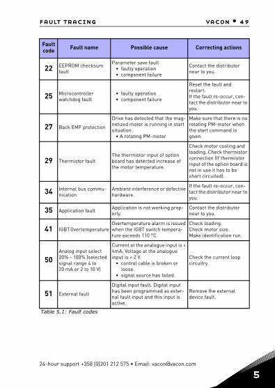
22 EEPROM checksum fault
Parameter save fault• faulty operation• component failure
Contact the distributor near to you.
25 Microcontroller watchdog fault
• faulty operation• component failure
Reset the fault and restart.If the fault re-occur, con-tact the distributor near to you.
27 Back EMF protection
Drive has detected that the mag-netized motor is running in start situation.
• A rotating PM-motor
Make sure that there is no rotating PM-motor when the start command is given.
29 Thermistor faultThe thermistor input of option board has detected increase of the motor temperature.
Check motor cooling and loading. Check thermistor connection (If thermistor input of the option board is not in use it has to be short circuited).
34 Internal bus commu-nication
Ambient interference or defective hardware.
If the fault re-occur, con-tact the distributor near to you.
35 Application fault Application is not working prop-erly.
Contact the distributor near to you.
41 IGBT Overtemperature Overtemperature alarm is issued when the IGBT switch tempera-ture exceeds 110 °C.
Check loading.Check motor size.Make identification run.
50Analog input select 20% - 100% (selected signal range 4 to 20 mA or 2 to 10 V)
Current at the analogue input is < 4mA; Voltage at the analogue input is < 2 V.
• control cable is broken or loose.
• signal source has failed.
Check the current loop circuitry.
51 External fault
Digital input fault. Digital input has been programmed as exter-nal fault input and this input is active.
Remove the external device fault.
Fault code Fault name Possible cause Correcting actions
Table 5.1: Fault codes
24-hour support +358 (0)201 212 575 • Email: [email protected]
5

50 • vacon fault tracing
5
52 Door Panel fault Control place is keypad, but door panel has been disconnected.
Check the connection between optional board and API. If connection is correct, contact the near-est Vacon distributor.
53 Fieldbus faultThe data connection between the fieldbus Master and the fieldbus of the drive has broken.
Check installation.If installation is correct, contact the nearest Vacon distributor.
54 Slot fault The connection between optional board and API has been broken.
Check board and slot. Contact the nearest Vacon distributor.
55 Wrong run fault Run forward and backward are high at the same time.
Check I/O control signal 1 and I/O control signal 2.
57 Idenfication fault Identification run has failed.
Run command was removed before comple-tion of identification run.Motor is not connected to frequency converter.There is load on motor shaft.
60 Regulated pump loss Pump is not connected Check the connection of the pump
80 Interlock start fault Check DIN input signal.
81 Auto turning done fault
Check transducer or man force stop when auto turn-ing.
82 Under min. frequency fault Check motor or load.
84 Over pressure Check transducer or parameter limit.
Fault code Fault name Possible cause Correcting actions
Table 5.1: Fault codes
Tel. +358 (0)201 2121 • Fax +358 (0)201 212205
vacon 20 api vacon • 51
API I/O si
10 V/50
0~20 m
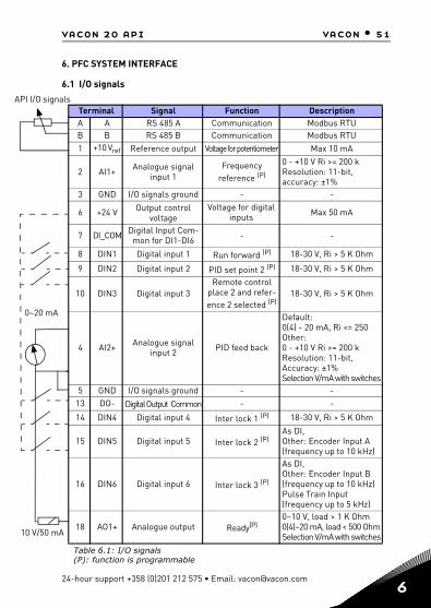
6. PFC SYSTEM INTERFACE
6.1 I/O signals
Terminal Signal Function DescriptionA A RS 485 A Communication Modbus RTU B B RS 485 B Communication Modbus RTU 1 +10 Vref Reference output Voltage for potentiometer Max 10 mA
2 AI1+ Analogue signal input 1
Frequency reference (P)
0 - +10 V Ri >= 200 k Resolution: 11-bit, accuracy: ±1%
3 GND I/O signals ground - -
6 +24 V Output control voltage
Voltage for digital inputs Max 50 mA
7 DI_COM Digital Input Com-mon for DI1-DI6 - -
8 DIN1 Digital input 1 Run forward (P) 18-30 V, Ri > 5 K Ohm
9 DIN2 Digital input 2 PID set point 2 (P) 18-30 V, Ri > 5 K Ohm
10 DIN3 Digital input 3 Remote control
place 2 and refer-ence 2 selected (P)
18-30 V, Ri > 5 K Ohm
4 AI2+ Analogue signal input 2 PID feed back
Default: 0(4) - 20 mA, Ri <= 250 Other: 0 - +10 V Ri >= 200 k Resolution: 11-bit, Accuracy: ±1% Selection V/mA with switches
5 GND I/O signals ground - - 13 DO- Digital Output Common - -
14 DIN4 Digital input 4 Inter lock 1 (P) 18-30 V, Ri > 5 K Ohm
15 DIN5 Digital input 5 Inter lock 2 (P) As DI,Other: Encoder Input A (frequency up to 10 kHz)
16 DIN6 Digital input 6 Inter lock 3 (P)
As DI,Other: Encoder Input B (frequency up to 10 kHz) Pulse Train Input (frequency up to 5 kHz)
18 AO1+ Analogue output Ready(P) 0~10 V, load > 1 K Ohm 0(4)~20 mA, load < 500 OhmSelection V/mA with switches
Table 6.1: I/O signals(P): function is programmable
gnals
mA
A
24-hour support +358 (0)201 212 575 • Email: [email protected]
52 • vacon vacon 20 api
6
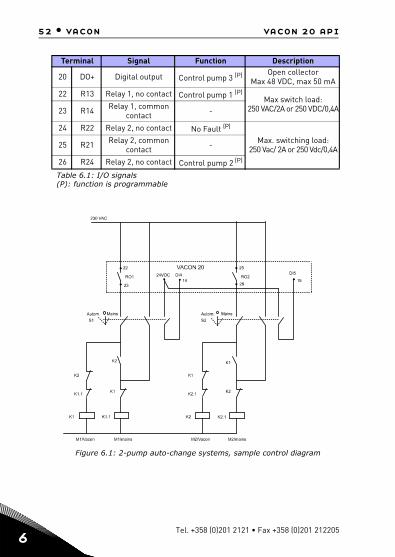
Figure 6.1: 2-pump auto-change systems, sample control diagram
20 DO+ Digital output Control pump 3 (P) Open collector
Max 48 VDC, max 50 mA
22 R13 Relay 1, no contact Control pump 1 (P) Max switch load: 250 VAC/2A or 250 VDC/0,4A23 R14 Relay 1, common
contact -
24 R22 Relay 2, no contact No Fault (P) Max. switching load:
250 Vac/ 2A or 250 Vdc/0,4A25 R21 Relay 2, common contact -
26 R24 Relay 2, no contact Control pump 2 (P)
Terminal Signal Function Description
Table 6.1: I/O signals(P): function is programmable
Tel. +358 (0)201 2121 • Fax +358 (0)201 212205

vacon 20 api vacon • 53
Figure 6.2: 3-pump auto-change systems, sample control diagram
24-hour support +358 (0)201 212 575 • Email: [email protected]
54 • vacon vacon 20 api
6
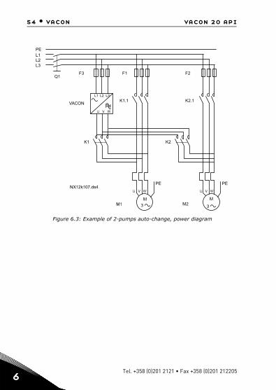
Figure 6.3: Example of 2-pumps auto-change, power diagram
VACON
K1
L1
L1
L2
L2
L3
L3
Q1F3 F1 F2
PE
PEPE
K1.1 K2.1
K2
Tel. +358 (0)201 2121 • Fax +358 (0)201 212205

vacon 20 api vacon • 55
Figure 6.4: Example of 3-pumps auto-change, power diagram
Figure 6.5: Microswitchs
Vacon 20 I / O terminals:
DI
En
coN
or
AO
Vm
A
AI2
Vm
A
RS
485
-te
rm
ON
S1S2S3S4J500
OFF
4 5 13 14 15 16 2018
1 2 3 6 7 8 9 10
22 23 26
2425
AI2 GND DO- DI4 DI5 DI6 AO DO+ R13 R14 * R24
+10VAI1 GND 24V DI-C DI1 DI2 DI3 A B R21 R22
24-hour support +358 (0)201 212 575 • Email: [email protected]

56 • vacon control panel
7
7. CONTROL PANEL
7.1 GeneralThe panel is an irremovable part of the drive consisting of corresponding control board; The overlay with display status on the cover and the button are in clarifica-tions in the user language.The User Panel consists of an alphanumeric LCD display with backlight and a keypad with the 9 push buttons (see Figure 7.1).
7.2 DisplayThe display includes 14-segment and 7-segment blocks, arrowheads and clear text unit symbols. The arrowheads, when visible, indicate some information about the drive, which is printed in clear text in user language on the overlay (numbers 1…14 in the figure below). The arrowheads are grouped in 3 groups with the following meanings and English overlay texts (see Figure 7.1):
Group 1 - 5; Drive status1= Drive is ready to start (READY)2= Drive is running (RUN)3= Drive has stopped (STOP)4= Alarm condition is active (ALARM)5= Drive has stopped due to a fault (FAULT)
Group 6 - 10; Control selectionsWhen API is operated by PC control, there are no arrowhead at I / O, KEYPAD and BUS.
6= Motor is rotating forward (FWD) 7= Motor is rotating reverse (REV) 8= I/O terminal block is the selected control place (I / O) 9= Keypad is the selected control place (KEYPAD) 10= Fieldbus is the selected control place (BUS)
Group 11 - 14; Navigation main menu 11= Reference main menu (REF) 12= Monitoring main menu (MON) 13= Parameter main menu (PAR) 14= System main menu (SYS)
Tel. +358 (0)201 2121 • Fax +358 (0)201 212205

control panel vacon • 57
Figure 7.1: Vacon 20 Control panel
7.3 KeypadThe keypad section of the control panel consists of 9 buttons (see Figure 7.1). The buttons and their functions are described as Table 7.1. The drive stops by pressing the keypad STOP button, regardless of the selected con-trol place when Par. 2.7 (Keypad stop button) is 1. If Par. 2.7 is 0, the drive stops by keypad STOP button only when control place is keypad. The drive starts by pressing the keypad START button when the selected control place is KEYPAD or LOCAL con-trol.
1 2 3 4 5
6 7 8 9 10
11
13
14
12
READY RUN STOP ALARM FAULT
FWD REV I/O KEYPAD BUS
SYS
PAR
REF
MON
BACKRESET
LOCREM
OK
24-hour support +358 (0)201 212 575 • Email: [email protected]
7
58 • vacon control panel
7
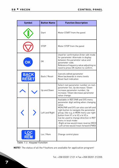
NOTE! The status of all the 9 buttons are available for application program!
Symbol Button Name Function Description
Start Motor START from the panel
STOP Motor STOP from the panel
OK
Used for confirmation.Enter edit mode for parameter. Alternate in display between the parameter value and parameter code.Reference frequency value adjusting no need to press OK-button to confirm.
Back / ResetCancels edited parameterMove backwards in menu levelsReset fault indication
Up and Down
Select root parameter number on root-parameter list, Up decrease / Down increase parameter number, Up increase / Down decrease parameter value change.
Left and Right
Available in REF,PAR and SYS menu parameter digit setting when changing value.MON,PAR and SYS can also use left and right button to navigate the parameter group, like e.g.,in MON menu use right button from V1.x to V2.x to V3.x.Can be used to change direction in REF menu in local mode:-Right arrow would mean reverse (REV)-Left arrow would mean forward (FWD)
Loc / Rem Change control place
Table 7.1: Keypad Function
OK
BACKRESET
LOCREM
Tel. +358 (0)201 2121 • Fax +358 (0)201 212205

control panel vacon • 59
7.4 Navigation on the Vacon 20 control panelThis chapter provides you with information on navigating the menus on Vacon 20 and editing the values of the parameters.
7.4.1 Main menu
The menu structure of Vacon 20 control software consists of a main menu and sev-eral submenus. Navigation in the main menu is shown below:
Figure 7.2: The main menu of Vacon 20
F WD R EV I/O K EY PAD BUS
RE F
M ON
PAR
SYS SYS
SYS SYS
SYS SYS
SYS SYS
FA ULTALAR MS TO PRE AD Y RU N
FW D REV I/O KEY PAD BU S
RE F
PA R
FAULTALARMS T OPR EAD Y RUN
MO N
F W D REV I/O KEY PAD BUS
RE F
PAR
FAUL TA LA RMSTO PREAD Y RUN
M ON
FW D RE V I/O KE YP AD BU S
REF
PAR
F AULTALARMS TO PRE AD Y RUN
MO N
F W D RE V I/O KE YP AD BU S
REF
PAR
F AULTALARMS TO PRE AD Y RUN
MO N
F W D RE V I/O KE YP A D BU S
REF
PAR
F AULTAL AR MS TO PRE A DY RU N
MO N
FW D RE V I/ O KE YP A D B US
R EF
PAR
FAU LTALAR MSTO PREAD Y RU N
MO N
PRES S
PRES S
PRES S
PRES S
PRESS
F WD REV I/O KEY PAD B US
RE F
M O N
PAR
FAULTALAR MS T OPRE ADY R U N
PRESS
PRESS
OK
OK
OK
OK
OK
In this menuyou canbrowse themonitoringvalues.
In this menuyou canbrowse andedit theparameters.
Dispalys thekeypad referencevalueregardless ofthe selectedcontron place.
Here you will beable to browsesystem parameterand faultsubmenu.
MONITORINGMENU
REFERENCEMENU
PARAMETERMENU
SYSTEMMENU
HzHz
24-hour support +358 (0)201 212 575 • Email: [email protected]
7

60 • vacon control panel
7
7.4.2 Reference menu
Figure 7.3: Reference menu display
Move to the reference menu with the UP / DOWN button (see Figure 7.2). The refer-ence value can be changed with UP / DOWN button as shown in Figure 7.3. If the value has big change, first press Left and Right buttons to select the digit which has to be changed, then press Up button to increase and Down button to decreases the value in the selected digit. The changing reference frequency will been taken into use immediately without pressing OK.
Note! LEFT and RIGHT buttons can be used to change the direction in Ref menu in local control mode.
Press to enteredit mode
Changevalue
OK
SYS
FWD REV I/O KEY PAD BUS
RE F
M O N
PAR
FAULTALAR MS TOPRE ADY R UN
Hz
Tel. +358 (0)201 2121 • Fax +358 (0)201 212205

control panel vacon • 61
7.4.3 Monitoring menu
Figure 7.4: Monitoring menu display
Monitoring values are actual values of measured signals as well as status of some control settings. It is visible in Vacon 20 display, but it can not be edited. See Chapter 8.2.Pressing Left/Right button to change the actual parameter to the first parameter of the next group, to browse monitor menu from V1.x to V2.1 to V3.1 to V4.1. After en-tering the desired group, the monitoring values can be browsed by pressing UP /DOWN button, as shown in Figure 7.4.In MON menu the selected signal and its value are alternateing in the display by pressing OK button.
Note! Turn on drive power, arrowhead of main menu is at MON, V x.x or monitor parameter value of Vx.x is displayed in Panel.Display Vx.x or monitor parameter value of Vx.x is determined by the last show status before power shut down. E.g., it was V4.5, and it is also V4.5 when restart.
OK
OK
OK
1 2
3
Press Left/Right to browseother Monitoring groups
Prsess Down tobrowse V4.5
5 Press OK V4.5 is display
4 Preess OK the value isdisplayed
FAULTALARMSTOPREADY RU N
REF
M ON
PAR
SYS
RE F
M ON
PAR
SYS
FAULTALARMS TOPREADY RU N
FWD R EV I/O K EYPAD BUS FWD R EV I/O K EYPAD BUS
Press OK to enterMonitoring menu
RE F
M ON
PAR
SYS
FAULTALARMS TOPREADY RU N
FWD R EV I/O K EYPAD BUS
REF
M ON
PAR
SYS
FAULTALARMSTOPREADY RU N
FWD R EV I/O K EYPAD BUS
FAULTALARMS TOPREADY RU N
REF
MON
PAR
SYS
FWD R EV I/O K EYPAD BUS
24-hour support +358 (0)201 212 575 • Email: [email protected]
7
62 • vacon control panel
7
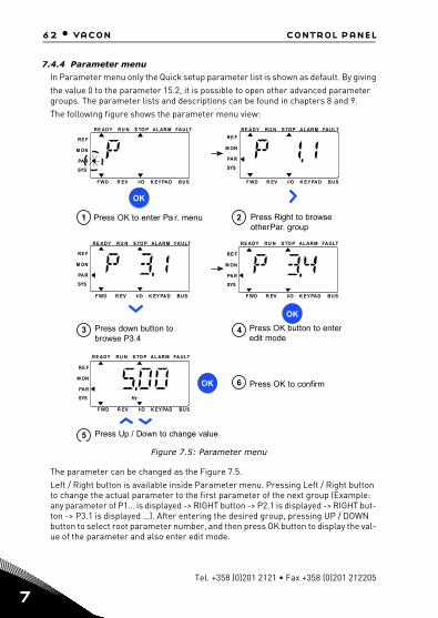
7.4.4 Parameter menu
In Parameter menu only the Quick setup parameter list is shown as default. By givingthe value 0 to the parameter 15.2, it is possible to open other advanced parameter groups. The parameter lists and descriptions can be found in chapters 8 and 9.The following figure shows the parameter menu view:
Figure 7.5: Parameter menu
The parameter can be changed as the Figure 7.5. Left / Right button is available inside Parameter menu. Pressing Left / Right button to change the actual parameter to the first parameter of the next group (Example: any parameter of P1… is displayed -> RIGHT button -> P2.1 is displayed -> RIGHT but-ton -> P3.1 is displayed …). After entering the desired group, pressing UP / DOWN button to select root parameter number, and then press OK button to display the val-ue of the parameter and also enter edit mode.
OK
OK
2 Press Right to browseotherPar. group
4 Press OK button to enteredit mode
3 Press down button tobrowse P3.4
5 Press Up / Down to change value
OK 6 Press OK to confirm
FAULTALAR MS TO PRE ADY RU N
RE F
M ON
PAR
SYS
RE F
M ON
PAR
SYS
RE F
M ON
PAR
SYS
FAULTALARMS TO PRE ADY RU N
FAULTALARMS TO PRE ADY RU N
FWD R EV I/O K EY PAD BUS F WD R EV I/O K EY PAD BUS
F WD R EV I/O K EY PAD BUS
1 Press OK to enter Pa r. menu
FAULTALARMS TO PRE ADY RU N
RE F
M ON
PAR
SYS
F WD R EV I/O K EY PAD BUS
FAULTALARMS TO PRE ADY RU N
RE F
M ON
PAR
SYS
F WD R EV I/O K EY PAD BUS
Hz
Tel. +358 (0)201 2121 • Fax +358 (0)201 212205
control panel vacon • 63
In edit mode, Left and Right buttons are used to select the digit which has to be changed, and Up increases / Down decreases parameter value.In edit mode, the value of Px.x is displayed blinkingly in the panel. After about 10 s, Px.x is displayed in the panel again if you don't press any button.
Note! In edit mode, if you edit the value and don't press OK button, the value isn't changed successfully. In edit mode, if you don't edit the value, you can press Reset /Back button to display Px.x again.
24-hour support +358 (0)201 212 575 • Email: [email protected]
7

64 • vacon control panel
7
7.4.5 System menu
SYS menu including fault submenu, field bus submenu and system parameter sub-menu, and the display and operation of the system parameter submenu is similar to PAR menu or MON menu.In system parameter submenu, there are some editable parameter (P) and some uneditable parameter (V).The Fault submenu of SYS menu includes active fault submenu and fault history sub-menu.
Figure 7.6: Fault menu
In active fault situation, FAULT arrow is blinking and the display is blinking active fault menu item with fault code. If there are several active faults, you can check it by entering the active fault submenu F5.x. F5.1 is always the latest active fault code. The active faults can be reset by pressing BACK / RESET button with long time (>2 s), when the API is in active fault submenu level (F5.x). If the fault cannot be reset, the blinking continues. It is possible to select other display menus during active fault, but in this case the display returns automatically to the fault menu if no button is pressed in 10 seconds. The fault code, subcode and the operating day, hour and minute val-ues at the fault instant are shown in the value menu (operating hours = displayed reading).
OK
Press OK to enter V1.11Press Left/Right buttonto browse other groups
2
Press down to browseother active faults
3
REF
MON
PAR
SYS
FAULTALARMSTOP
FWD REV I/O KEYPAD BUS
READY RUN
OK
Press OK to select one faultto browse its time
4
REF
MON
PAR
SYS
FAULTALARMSTOPREADY RUN
FWD REV I/O KEYPAD BUS
Browse for fault code(C xx),subcode(Id xx), days(d xx),hours(H xx), minutes(M xx)
5
REF
MON
PAR
SYS
FAULTALARMSTOPREADY RUN
FWD REV I/O KEYPAD BUS
REF
MON
PAR
SYS
FAULTALARMSTOPREADY RUN
FWD REV I/O KEYPAD BUS
REF
MON
PAR
SYS
FAULTALARMSTOPREADY RUN
FWD REV I/O KEYPAD BUS
Tel. +358 (0)201 2121 • Fax +358 (0)201 212205

control panel vacon • 65
Note! Fault History can be reset by long pressing the BACK / RESET button for 5 second time,when the API is in fault history sub-menu level (F6.x), it will also clear all active faults.
See Chapter 5 for fault descriptions.
24-hour support +358 (0)201 212 575 • Email: [email protected]
7
66 • vacon parameters
8
8. PFC APPLICATION PARAMETERS
On the next pages you can find the lists of parameters within the respective param-eter groups. The parameter descriptions are given in Chapter 9 .
Explanations:Code: Location indication on the keypad; Shows the operator the present
Monitoring value number or Parameter numberParameter: Name of monitoring value or parameterMin: Minimum value of parameterMax: Maximum value of parameterUnit: Unit of parameter value; given if availableDefault: Factory preset valueID: ID number of the parameter (used with fieldbus control)
Modifiable only in stop state
NOTE: This manual is for Vacon 20 standard application only. If you need more ap-plication information, please download the appropriate user manual on http://www.vacon.com -> Downloads.
Tel. +358 (0)201 2121 • Fax +358 (0)201 212205

parameters vacon • 67
8.1 Startup wizard
The startup wizard ask the following questions.
1. Motor Nominal Speed
2. Motor Nominal Current
3. Auto-change Mode
4. Number of Auxiliary Pumps
And configure parameters as in the table below.
8.2 Monitor
Read only variables that report of signals and drive/motor measurements.
8.2.1 Basic
Code Parameter ID Description
P1.1 Normal voltage of the motor 110 From motor name plate
P1.2 Normal frequency of the motor 111 From motor name plate
P1.3 Motor nominal speed 112 From motor name plate
P1.4 Motor nominal current 113 From motor name plate
P1.5 Motor cos fi 120 From motor name plate
P3.1 Minimum frequency 101 Minimum allowed frequency reference.
P14.1 Auto-change Mode 1623
0 = No Auto-change1 = Aux. auto-change without interlocks2 = Auto-change all without interlocks3 = Aux. auto-change with interlocks4 = Auto-change all with interlocks
P14.2 Number of Auxiliary Pumps 1600 Auxiliary pumps in the system
P14.3 Desired work pressure 1670 Desired work pressure in kg
Code Monitor Unit ID Description
V1.1 Output Frequency Hz 1 Output frequency to motor
V1.2 Frequency Reference Hz 25 Frequency reference to motor control
V1.3 Motor speed rpm 2 Estimated motor speed
V1.4 Motor current A 3
V1.5 Motor torque % 4 As % of motor nominal torque
V1.6 Motor shaft power % 5 As % of motor nominal power
24-hour support +358 (0)201 212 575 • Email: [email protected]
8

68 • vacon parameters
8
8.2.2 I/O
V1.7 Motor voltage V 6 Output voltage to motor.
V1.8 DC link voltage V 7 Voltage on the DC-Link
V1.9 Drive temperature °C 8 Heat sink temperature
V1.10 Motor temperature % 9 Estimated motor temperature
V1.11 Output Power kW 79 Output power from drive to motor
Code Monitor Unit ID Description
V2.1 Analogue input 1 % 59 Analogue input AI1
V2.2 Analogue input 2 % 60 Analogue input AI2
V2.3 Analogue output % 81 Analogue output
V2.4 DIN1, DIN2, DIN3 15 Digital inputs state
V2.5 DIN4, DIN5, DIN6 16 Digital inputs state
V2.6 RO1, RO2, DO 17 Digital outputs state
V2.14 DIE1, DIE2, DIE3 33
This monitor value shows status of the digital inputs 1-3 from option board, hidden until an option board is connected.
V2.15 DIE4, DIE5, DIE6 34
This monitor value shows status of the digital inputs 4-6 from option board, hidden until an option board is connected.
V2.16 DOE1, DOE2, DOE3 35
This monitor value shows status of the relay outputs1-3 from option board, hidden until an option board is connected.
V2.17 DOE4, DOE5, DOE6 36
This monitor value shows status of the relay outputs4-6 from option board, hidden until an option board is connected.
Code Monitor Unit ID Description
Tel. +358 (0)201 2121 • Fax +358 (0)201 212205
parameters vacon • 69
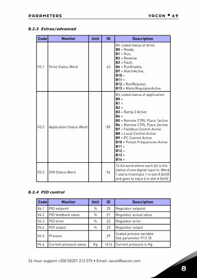
8.2.3 Extras/advanced
8.2.4 PID control
Code Monitor Unit ID Description
V3.1 Drive Status Word 43
Bit coded status of drive. B0 = Ready, B1 = Run, B2 = Reverse B3 = Fault, B6 = RunEnable, B7 = AlarmActive, B10 = B11 = B12 = RunRequest, B13 = MotorRegulatorActive
V3.2 Application Status Word 89
Bit coded status of application.B0 = B1 = B2 = B3 = Ramp 2 Active B4 = B5 = Remote CTRL Place 1activeB6 = Remote CTRL Place 2activeB7 = Fieldbus Control Active B8 = Local Control Active B9 = PC Control Active B10 = Preset Frequencies Active B11 = B12 = B13 = B14 =
V3.3 DIN Status Word 56
16 bit word where each bit is the status of one digital input in. Word 1 starts frominput 1 in slot A (bit0) and goes to input 6 in slot A (bit5).
Code Monitor Unit ID Description
V4.1 PID setpoint % 20 Regulator setpoint
V4.2 PID feedback value % 21 Regulator actual value
V4.3 PID error % 22 Regulator error
V4.4 PID output % 23 Regulator output
V4.5 Process 29 Scaled process variableSee parameter P13.18
V4.6 Current pressure value Kg 1616 Current pressure in Kg
24-hour support +358 (0)201 212 575 • Email: [email protected]
8

70 • vacon parameters
8
Tel. +358 (0)201 2121 • Fax +358 (0)201 212205
8.3 Main parameters lists (Menu PAR)
8.3.1 Motor settings
Code Parameter Min Max Unit Default ID Description
Motor nominal volt-age 180 690 V varies 110 From motor name plate
Motor nominal fre-quency 30,00 320,00 Hz 50,00/
60,00 111 From motor name plate
Motor nominal speed 30 20000 rpm 1440/
1720 112 From motor name plate
Motor nominal cur-rent
0,2 x In 2 x In A In 113 From motor name plate
Motor cos phi 0,30 1,00 0,85 120 From motor name plate
Motor type 0 1 0 650 0 = Induction 1 = Permanent magnet
Current limit 0,2 x In 2 x In A 1,5 x In 107 Maximum motor current
Motor control mode 0 1 0 600 0: Frequency control 1: Open loop speed control
U/f ratio * 0 2 0 108 0: Linear 1: Quadratic 2: Programmable
Field weakening point * 8,00 320,00 Hz 50.00/
60,00 602 Field weakening point frequency
Field weakening point voltage * 10,00 200,00 % 100,00 603
Voltage at field weaken-ing point as % of Unmot
U/f mid point frequency * 0,00 P1.10 Hz 50.00/
60,00 604 Mid point frequency for programmable U/f
U/f mid point voltage * 0,00 P1.11 % 100,00 605
Mid point voltage for programmable U/f as % of Unmot
Zero freq voltage * 0,00 40,00 % varies 606
Voltage at 0 Hz as % of Unmot
Torque Boost 0 1 0 109 0: Disabled 1: Enabled
Switching frequency 1,5 16,0 kHz 4,0/2,0 601
PWM frequency. Values higher than default reduce the current capacity.
P1.1
P1.2
P1.3
P1.4
P1.5
P1.6
P1.7
P1.8
P1.9
P1.10
P1.11
P1.12
P1.13
P1.14
P1.15
P1.16

parameters vacon • 71
24-hour support +358 (0)201 212 575 • Email: [email protected]
* parameter is automatically set by motor identification
BrakeChopper 0 2 0 504 0: Disabled 1: Enabled: Always 2: Enabled: Run state
Brake chopper level 0 Varies V 911 1267
Brake chopper control activation level in volt. For 240V Supply: 240*1.35*1.18 = 382V For 400V Supply: 400*1.35*1.18 = 638V Please note that when brake chopper is used the overvoltage control-ler can be switched off or the overvoltage refer-ence level can be set above the brake chop-per level.
Motor identification 0 1 0 631
0: not active 1: standstill identifica-tion (needs run com-mand within 20s to activate)
Rs voltage drop * 0.00 100.00 % 0,00 662 Voltage drop over motor windings as % of Unmot at nominal current.
Overvoltage controller 0 2 1 607
0 = Disabled 1 = Enabled, Standard Mode 2 = Enabled, Shock Load Mode
Undervoltage con-troller 0 1 1 608 0 = Disabled
1 = Enabled
Sine filter 0 1 0 522 0 = Not in use 1 = In use
Modulator type 0 65535 28928 648
Bit 1 = Discontinuous modulation Bit 2 = Pulse dropping in overmodulation Bit 6 = Under modulationBit 8 = Instantaneous DC voltage compensationBit 11 = Low noiseBit 12 = Dead time compensationBit 13 = Flex error compensation
Code Parameter Min Max Unit Default ID Description
P1.17
P1.18
P1.19
P1.20
P1.21
P1.22
P1.23
P1.24
8

72 • vacon parameters
8
8.3.2 Start/stop setup
Code Parameter Min Max Unit Default ID Description
P2.1 Remote Control Place 1 Selection 0 2 0 172
Run and direction control 0: I/O terminals 1: Fieldbus2: Keypad
Start function 0 1 0 505 0: Ramping 1: Flying start
Stop function 0 1 1 506 0: Coasting 1: Ramping
P2.4 I/O Start stop logic 0 4 0 300
Logic = 0 I/O Ctrl Signal 1 = Forward I/O Ctrl Signal 2 = Backward Logic = 1I/O Ctrl Signal 1 = Forward (edge) I/O Ctrl Signal 2 = Inverted Stop Logic = 2 I/O Ctrl Signal 1= Forward (edge) I/O Ctrl Signal 2= Backward (edge) Logic = 3 I/O Ctrl Signal 1 = Start I/O Ctrl Signal 2 = Reverse Logic = 4 I/O Ctrl Signal 1 = Start (edge) I/O Ctrl Signal 2 = Reverse
P2.5 Local/Remote 0 1 0 211
Parameter for switching between local and remote. Same parame-ter is accessed from loc/rem button. Local is always keypad. 0 = Remote Ctrl 1 = Local Ctrl
P2.6 Keypad control direction 0 1 0 123
Only valid if control place is keypad. 0: Forward 1: Reverse
P2.7 Keypad stop button 0 1 1 114
Defines when keypad stop button is enabled. 0: Keypad control only 1: Always
P2.2
P2.3
Tel. +358 (0)201 2121 • Fax +358 (0)201 212205

parameters vacon • 73
8.3.3 References
8.3.4 Ramps and brakes
P2.8 Remote Control place 2 selection 0 2 0 173
Alternative run and direction control place. Forced from digital input. 0: I/O terminals 1: Fieldbus 2: Keypad
Keypad button lock 0 1 0 1552
0
0 = Unlock all the keypad button1 = Loc/Rem button locked
Code Parameter Min Max Unit Default ID Description
Min frequency 0,00 P3.2 Hz 30,00 101 Minimum freq reference
Max frequency P3.1 320,00 Hz 51,00/ 61,00 102 Maximum freq reference
P3.3
Remote control place1 fre-
quency reference selection
1 Varies 6 117
Freq reference control 1: Preset Speed 0 2: Keypad 3: Fieldbus 4: AI1 5: AI2 6: PID 7: AI1+AI2
P3.4 Preset Speed 0 P3.1 P3.2 Hz 10,00 180 Base speed when fre-quency reference selec-tion is = Preset Speed 0.
P3.5
Remote control place2 fre-
quency reference selection
1 Varies 1 131 Same as Remote Control Place1.
Code Parameter Min Max Unit Default ID Description
Ramp S-shape 0.0 10.0 s 0.0 500 S-curve time ramp
Acceleration time1 0,1 3000,0 s 5,0 103 Time from 0 to max
frequency
Code Parameter Min Max Unit Default ID Description
P2.9
P3.1
P3.2
P4.1
P4.2
24-hour support +358 (0)201 212 575 • Email: [email protected]
8

74 • vacon parameters
8
Deceleration time 1 0,1 3000,0 s 5,0 104 Time from max
frequency to 0
Ramp S-shape 2 0.0 10.0 s 0.0 501 S-curve time ramp
Acceleration time 2 0,1 3000,0 s 60,0 502 Time from 0 to max
frequency
Deceleration time 2 0,1 3000,0 s 10,0 503 Time from max
frequency to 0
Flux Braking 0 3 0 520
0 = Off 1 = Deceleration 2 = Chopper 3 = Full Mode
Flux Braking Current
0,5x In 2 x In A varies 519 Defines the current level for fluxbraking
DC braking current
0,3 x In 2 x In A In 507 DC current for braking
Stop DC current time 0,00 600,00 s 0,00 508 DC current time at stop
0: not active
Stop DC current frequency 0,10 10,00 Hz 1,50 515 Frequency under which
DC current starts
Start DC current time 0,00 600,00 s 0,00 516 DC current time at start
0: not active
P4.13 Accel2 Freq Threshold 0,00 P3.2 Hz 0,00 527
Threshold for auto change from acceleration time1 to 2 0,00 = disabled
P4.14 Decel2 Freq Threshold 0,00 P3.2 Hz 0,00 528
Threshold for auto change from deceleration time 2 to 1 0,00 = disabled
Code Parameter Min Max Unit Default ID Description
P4.3
P4.4
P4.5
P4.6
P4.7
P4.8
P4.9
P4.10
P4.11
P4.12
Tel. +358 (0)201 2121 • Fax +358 (0)201 212205

parameters vacon • 75
8.3.5 Digital inputs
Code Parameter Min Max Unit Default ID Description
P5.1 I/O Ctrl Signal 1 0 Varies 1 403
See P2.4 for function 0: not used 1: DIN12: DIN23: DIN34: DIN45: DIN56: DIN67: DIE18: DIE29: DIE310: DIE411: DIE512: DIE6
P5.2 I/O Ctrl signal 2 0 Varies 0 404 SeeP2.6 for functions See P5.1 for selections
P5.3 Reverse 0 Varies 0 412 Independent from P2.4 See P5.1 for selections
P5.4 Ext fault closed 0 Varies 0 405 Fault if signal high See P5.1 for selections
P5.5 Ext fault open 0 Varies 0 406 Fault is signal lowSee P5.1 for selections
P5.6 Fault reset 0 Varies 0 414 Fault reset (on edge)See P5.1 for selections
P5.7 Run enable 0 Varies 0 407 Enables motor controlSee P5.1 for selections
P5.8 Ramp time 2 selection 0 Varies 0 408 Activates ramp 2
See P5.1 for selections
P5.9 Remote control place 2 0 Varies 3 425 Activates control place 2
See P5.1 for selections
P5.10 Remote control
place freq reference 2
0 Varies 3 343 Activates reference 2See P5.1 for selections
P5.11 PID setpoint 2 0 Varies 2 1047 Activates setpoint 2See P5.1 for selections
P5.12 Inter lock 1 0 6 4 1621
P5.13 Inter lock 2 0 6 5 1622
P5.14 Inter lock 3 0 6 6 1623
24-hour support +358 (0)201 212 575 • Email: [email protected]
8
76 • vacon parameters
8
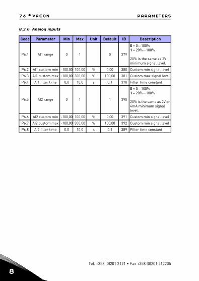
8.3.6 Analog inputs
Code Parameter Min Max Unit Default ID Description
P6.1 AI1 range 0 1 0 379
0 = 0—100%1 = 20%—100%
20% is the same as 2V minimum signal level.
P6.2 AI1 custom min -100,00 100,00 % 0,00 380 Custom min signal level
P6.3 AI1 custom max -100,00 300,00 % 100,00 381 Custom max signal level
P6.4 AI1 filter time 0,0 10,0 s 0,1 378 Filter time constant
P6.5 AI2 range 0 1 1 390
0 = 0—100%1 = 20%—100%
20% is the same as 2V or 4mA minimum signal level.
P6.6 AI2 custom min -100,00 100,00 % 0,00 391 Custom min signal level
P6.7 AI2 custom max -100,00 300,00 % 100,00 392 Custom min signal level
P6.8 AI2 filter time 0,0 10,0 s 0,1 389 Filter time constant
Tel. +358 (0)201 2121 • Fax +358 (0)201 212205

parameters vacon • 77
8.3.7 Digital outputs
Code Parameter Min Max Unit Default ID Description
P7.1 RO1 signal selection 0 23 9 313
0: Not used 1: Ready 2: Run 3: Fault 4: Fault inverted 5: Warning 6: Reverse 7: At speed 8: Motor regulator active 9: Ctr.Pump 1 10: Ctr.Pump 2 11: Ctr.Pump 3
P7.2 RO2 signal selection 0 Varies 10 314 See P7.1
P7.3 DO1 signal selection 0 Varies 11 312 See P7.1
P7.4 RO1 inversion 0 1 0 1587 0: no inversion 1: inverted
P7.5 RO2 inversion
0 1 0 1588 0: no inversion1: inverted
P7.6 DOE1 signal selection 0 Varies 0 317
As parameter 8.1, hidden until an option board is connected.
P7.7 DOE2 signal selection 0 Varies 0 318
As parameter 8.1, hidden until an option board is connected.
P7.8 DOE3 signal selection 0 Varies 0 1386
As parameter 8.1, hidden until an option board is connected.
P7.9 DOE4 signal selection 0 Varies 0 1390
As parameter 8.1, hidden until an option board is connected.
P7.10 DOE5 signal selection 0 Varies 0 1391
As parameter 8.1, hidden until an option board is connected.
P7.11 DOE6 signal selection 0 Varies 0 1395
As parameter 8.1, hidden until an option board is connected.
24-hour support +358 (0)201 212 575 • Email: [email protected]
8

78 • vacon parameters
8
8.3.8 Analog outputs
P7.12 AO as Digital Output enable 0 1 0 1621 enable AO as DO function
P7.13 Digital Output (AO) 0 3 0 1624
0 = ready1 = run2 = Fault3 = Fault inverted
Note! Must active AO as Digitaloutput by parameter
Code Parameter Min Max Unit Default ID Description
P8.1 Analog output signal selection 0 14 1 307
0: Test 0% (Not used) 1: Output freq (0— fmax)2: Output current (0—InMotor) 3: Motor torque (0—TnMotor) 4: PID output (0-100%) 5: Freq refer (0— fmax)6: Motor speed (0 – nmax) 7: Motor power (0—PnMotor) 8: Motor Voltage (0- UnMotor) 9: DC-link Voltage (0-1000V) 10:Process Data In1(0-10000)11: Process Data In2(0-10000)12: Process Data In3(0-10000)13: Process Data In4(0-10000)14: Test 100%
P8.2 Analog output minimum 0 1 0 310 0 = 0 mA
1 = 4 mA
P8.3 Analog output scaling 0,0 1000,0 % 100,0 311 Scaling factor
P8.4 Analog output filter time 0,00 10,00 s 0,10 308 Filter time
Code Parameter Min Max Unit Default ID Description
Tel. +358 (0)201 2121 • Fax +358 (0)201 212205

parameters vacon • 79
8.3.9 Fieldbus data-Mapping
8.3.10 Prohibited frequencies
Code Parameter Min Max Unit Default ID Description
P9.1 FB Data Out1 Sel 0 Varies 0 852
Variable mapped on PD10: Frequency reference1: Output frequency2: Motor speed3: Motor current4: Motor voltage5: Motor torque6: Motor power7: DC link voltage8: Active fault code9: Analogue AI110: Analogue AI211: Digital inputs state12: PID feedback value13: PID setpoint
P9.2 FB Data Out2 Sel 0 Varies 1 853 Variable mapped on PD2
P9.3 FB Data Out3 Sel 0 Varies 2 854 Variable mapped on PD3
P9.4 FB Data Out4 Sel 0 Varies 4 855 Variable mapped on PD4
P9.5 FB Data Out5 Sel 0 Varies 5 856 Variable mapped on PD5
P9.6 FB Data Out6 Sel 0 Varies 3 857 Variable mapped on PD6
P9.7 FB Data Out7 Sel 0 Varies 6 858 Variable mapped on PD7
P9.8 FB Data Out8 Sel 0 Varies 7 859 Variable mapped on PD8
P9.9 Aux CW Data In Sel 0 5 0 1167
PDI for Aux CW0: Not used1: PDI12: PDI23: PDI34: PDI45: PDI5
Code Parameter Min Max Unit Default ID Description
P10.1 Prohibit Fre-
quency Range 1 Low Limit
0,00 P3.2 Hz 0,00 509 Low limit
P10.2 Prohibit Fre-
quency Range 1 High Limit
0,00 P3.2 Hz 0,00 510 High limit
24-hour support +358 (0)201 212 575 • Email: [email protected]
8

80 • vacon parameters
8
8.3.11 Protections
P10.3 Prohibit Fre-
quency Range 2 Low Limit
0,00 P3.2 Hz 0,00 511 Low limit
P10.4 Prohibit Fre-
quency Range 2 High Limit
0,00 P3.2 Hz 0,00 512 High limit
Code Parameter Min Max Unit Default ID Description
P11.1 Analog Input low fault 0 4 4 700
0: No action1: Alarm2: Alarm, preset alarm frequency3: Fault: Stop function4: Fault: Coast
Under voltage fault 1 2 2 727
1: No response(no fault generated but drive still stopsmodulation) 2: Fault: Coast
Earth fault 0 3 2 703
0: No action1: Alarm2: Fault: Stop function3: Fault: Coast
Output Phase Fault 0 3 2 702
0: No Action1: Alarm2: Fault: Stop function3: Fault: Coast
Stall protection 0 3 0 709
0: No action1: Alarm2: Fault: Stop function3: Fault: Coast
Under load pro-tection 0 3 0 713
0: No action1: Alarm2: Fault: Stop function3: Fault: Coast
Motor thermal protection 0 3 2 704
0: No action1: Alarm2: Fault: Stop function3: Fault: Coast
Mtp: Ambient temperature –20 100 °C 40 705 Environment
temperature
Code Parameter Min Max Unit Default ID Description
P11.20
P11.3
P11.4
P11.5
P11.6
P11.7
P11.8
Tel. +358 (0)201 2121 • Fax +358 (0)201 212205

parameters vacon • 81
Mtp: Zero speed cooling 0,0 150,0 % 40,0 706 Cooling as % at 0 speed
Mtp: Thermal time constant 1 200 min varies 707 Motor thermal time
constant.
Stall Current 0.00 2xIN A IN 710
Stall time 0,00 300,00 s 15,00 711 Stall time limit
Stall frequency 0,10 320,00 Hz 25,00 712 Stall min frequency
UL: Field weakening load 10,0 150,0 % 50,0 714 Minimum torque at field
weakening
UL: Zero freq load 5,0 150,0 % 10,0 715 Minimum torque at F0
UL: Time limit 1,0 300,0 s 20,0 716 Underload time limit
P11.17 Analog Input low fault delay 0,0 10,0 s 0,5 1430 Time limit
External fault 0 3 2 701
0: No action1: Alarm2: Fault: Stop function3: Fault: Coast
P11.19 Fieldbus fault 0 4 3 733
0: No action1: Alarm2: Alarm, preset alarm frequency3: Fault: Stop function4: Fault: Coast
P11.20 Preset alarm frequency P3.1 P3.2 Hz 25.00 183
Frequency used when fault response is Alarm+preset Frequency
P11.21 Parameters edit lock 0 1 0 819 0: Edit enabled
1: Edit disabled
P11.22 FWD/REV con-flict supervision 0 3 1 1463 As parameter P13.3
P11.23 Low frequency protection time 0 99.99 10.00 1621
P11.24 Over pressure limit 0 200 % 150 1901 Over pressure limit
Code Parameter Min Max Unit Default ID Description
P11.9
P11.10
P11.11
P11.12
P11.13
P11.14
P11.15
P11.16
P11.18
24-hour support +358 (0)201 212 575 • Email: [email protected]
8
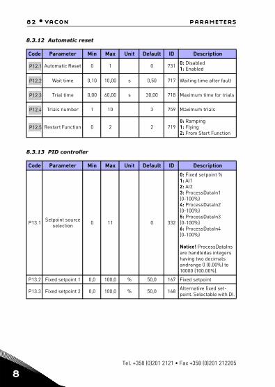
82 • vacon parameters
8
8.3.12 Automatic reset
8.3.13 PID controller
Code Parameter Min Max Unit Default ID Description
Automatic Reset 0 1 0 731 0: Disabled1: Enabled
Wait time 0,10 10,00 s 0,50 717 Waiting time after fault
Trial time 0,00 60,00 s 30,00 718 Maximum time for trials
Trials number 1 10 3 759 Maximum trials
Restart Function 0 2 2 719 0: Ramping1: Flying2: From Start Function
Code Parameter Min Max Unit Default ID Description
P13.1 Setpoint source selection 0 11 0 332
0: Fixed setpoint % 1: AI1 2: AI2 3: ProcessDataIn1(0-100%) 4: ProcessDataIn2(0-100%) 5: ProcessDataIn3(0-100%) 6: ProcessDataIn4(0-100%)
Notice! ProcessDataIns are handledas integers having two decimals andrange 0 (0.00%) to 10000 (100.00%).
P13.2 Fixed setpoint 1 0,0 100,0 % 50,0 167 Fixed setpoint
P13.3 Fixed setpoint 2 0,0 100,0 % 50,0 168 Alternative fixed set-point. Selectable with DI.
P12.1
P12.2
P12.3
P12.4
P12.5
Tel. +358 (0)201 2121 • Fax +358 (0)201 212205
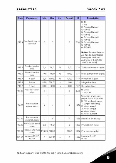
parameters vacon • 83
P13.4 Feedback source selection 0 7 1 334
0: AI1 1: AI2 2: ProcessDataIn1(0-100%) 3: ProcessDataIn2(0-100%)4: ProcessDataIn3(0-100%)5: ProcessDataIn4(0-100%)6: AI2-AI1
Notice! ProcessDataIns are handledas integers having two decimals andrange 0 (0.00%) to 10000 (100.00%).
P13.5 Feedback value min 0,0 50,0 % 0,0 336 Value at minimum signal
P13.6 Feedback value max 10,0 300,0 % 100,0 337 Value at maximum signal
P13.7 P gain 0,0 1000,0 % 125,0 118 Proportional gain
P13.8 I time 0,00 320,00 s 1,00 119 Integrative time
P13.9 D time 0,00 10,00 s 0,00 132 Derivative time
P13.10 PID error inver-sion 0 1 0 340 0: Direct
1: Inverted
P13.11 Process unit source select 0 6 0 1513
Selection of variable proportional to process 0: PID feedback value 1: Output frequency2: Motor speed3: Motor torque4: Motor power5: Motor current
P13.12 Process unit decimal digits 0 3 1 1035 Decimals on display
P13.13 Process unit min value 0.0 P15.21 0 1033 Process min value
P13.14 Process unit max value P15.20 3200.0 100.0 1034 Process max value
P13.15 Increase Ref. PIto run 0 162.75 s 5 1614 Increase Ref. PI
to run
Code Parameter Min Max Unit Default ID Description
24-hour support +358 (0)201 212 575 • Email: [email protected]
8
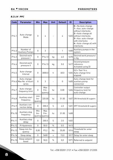
84 • vacon parameters
8
8.3.14 PFC
Code Parameter Min Max Unit Default ID Description
P14.1 Auto-change Mode 0 4 - 4 1603
0 = No Auto-change1 = Aux. auto-change without interlocks2 = Auto-change all without interlocks3 = Aux. auto-change with interlocks4 = Auto-change all with interlocks
P14.2 Number of Auxiliary Pumps 0 3 - 1 1600 Auxiliary pumps in the
system
P14.3 Desired work pressure I 0 P14.13 kg 4.0 1670 Desired work pressure I
in Kg
P14.4 Desired work pressure II 0 P14.13 kg 5.0 1617
Second pressure reference. Activated using DI
P14.5 Auto-change Interval 0 3000.0 h 48.0 1604
0,0 = Test 16 s. Auto-change time elapsed
P14.6 Auto-change:
Max No. of Auxil-iaries
0 3 - 0 1605 Auto-change level for auxiliary pump connection
P14.7 Auto-change: frequency limit 0
Max Fre-
quency hz 0.00 1606
Controller output frequency level for auto-change
P14.8 Auxiliary start frequency
min fre-
quency 320.00 hz 51.00 1607 ON threshold AI superv
P14.9 Auxiliary con-nection delay 0 200.0 S 4.0 1601 OFF threshold AI superv
P14.10 Auxiliary stop frequency
Min fre-
quency
Max Fre-
quency hz 31.00 1608
P14.11 Auxiliary stop delay 0 200.0 S 2.0 1602
P14.12 PI Hysteresis 0 50.0 % 0.5 1613
P14.13 Sleep min fre-quency 0,00 P3.2 Hz 35,00 1016 Threshold for enter
sleep
P14.14 Sleep delay 0 3600 s 15,0 1017 Delay for enter sleep
P14.15 Sleep setpoint boost 0,0 50,0 % 0,0 1071 Referred to setpoint
Tel. +358 (0)201 2121 • Fax +358 (0)201 212205

parameters vacon • 85
8.3.15 Application settings
8.4 System parameters
P14.16 Setpoint boost time 0 60 s 0,0 1072 Boost time after P8.13
P14.17 Sleep max loss 0,0 50,0 % 0,0 1509 Referred to feedback value after boost
P14.18 Sleep loss check time 1 300 s 0,0 1510 After boost time P8.16
P14.19 Wake up level 0,0 100,0 % 92,0 1611 Wake up level (%) of PID reference
P14.20 Interlock updat-ing 0 1 - 0 1620 0 = Always
1 = Only in Stop mode
P14.21 Pressure Trans-ducer scale 0 100.0 kg 10.0 1615
P14.22 Pressure unit select 0 1 1 1618 0 = %
1 = Kg
P14.23 Smart interlock-less 0 1 1 1612
0 = Disabled 1 = Enabled (When P14.1 = 2, the regulated pump is changed if is not con-nected)
Code Parameter Min Max Unit Default ID Description
P15.2 Parameter conceal 0 1 1 115
0 = All parameters visible1 = Only quick setupparameter group visible
Code Parameter Min Max Default ID Note
Software information (MENU PAR -> V1)
V1.1 API SW ID 2314
V1.2 API SW version 835
V1.3 Power SW ID 2315
V1.4 Power SW version 834
V1.5 Application ID 837
V1.6 Application revision 838
V1.7 System load 839
Code Parameter Min Max Unit Default ID Description
24-hour support +358 (0)201 212 575 • Email: [email protected]
8
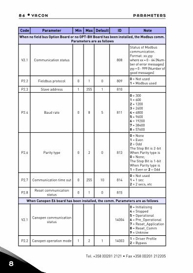
86 • vacon parameters
8
When no field bus Option Board or no OPT-BH Board has been installed, the Modbus comm. Parameters are as follows
V2.1 Communication status 808
Status of Modbus communication. Format: xx.yyy where xx = 0 - 64 (Num-ber of error messages) yyy = 0 - 999 (Number of good messages)
P2.2 Fieldbus protocol 0 1 0 809 0 = Not used1 = Modbus used
P2.3 Slave address 1 255 1 810
P2.4 Baud rate 0 8 5 811
0 = 3001 = 6002 = 12003 = 24004 = 48005 = 96006 = 192007 = 384008 = 57600
P2.6 Parity type 0 2 0 813
0 = None1 = Even2 = OddThe Stop Bit is 2-bit When Parity type is 0 = None; The Stop Bit is 1-bit When Parity type is 1 = Even or 2 = Odd
P2.7 Communication time out 0 255 10 8140 = Not used 1 = 1 sec 2 = 2 secs, etc
P2.8 Reset communication status 0 1 0 815
When Canopen E6 board has been installed, the comm. Parameters are as follows
V2.1 Canopen communication status 14004
0 = Initialising 4 = Stopped 5 = Operational 6 = Pre_Operational 7 = Reset_Application8 = Reset_Comm 9 = Unknow
P2.2 Canopen operation mode 1 2 1 14003 1 = Driver Profile2 = Bypass
Code Parameter Min Max Default ID Note
Tel. +358 (0)201 2121 • Fax +358 (0)201 212205

parameters vacon • 87
P2.3 Canopen Node ID 1 127 1 14001
P2.4 Canopen baud rate 1 8 6 14002
1 = 10 kBaud2 = 20 kBaud3 = 50 kBaud4 = 100 kBaud5 = 125 kBaud6 = 250 kBaud7 = 500 kBaud8 = 1000 kBaud
When DeviceNet E7 board has been installed, the comm. Parameters are as follows
V2.1 Communication status 14014
Status of Modbus com-munication. Format: XXXX.Y, X = DeviceNet msg counter, Y = DeviceNet status. 0 = Non-existent or no bus power. 1 = Configuring state 2 = Established 3 = Timeout
P2.2 Output assembly type 20 111 21 14012 20, 21, 23, 25, 101, 111
P2.3 MAC ID 0 63 63 14010
P2.4 Baud rate 1 3 1 140111 = 125 kbit/s2 = 250 kbit/s3 = 500 kbit/s
P2.5 Input assembly type 70 117 71 14013 70, 71, 73, 75, 107, 117
When ProfidBus E3/E5 board has been installed, the comm. Parameters are as follows
V2.1 Communication status 14022
V2.2 Fieldbus protocol status 14023
V2.3 Active protocol 14024
V2.4 Active buad rate 14025
V2.5 Telegram type 14027
P2.6 Operate mode 1 3 1 140211 = Profidrive2 = Bypass3 = Echo
P2.7 Slave address 2 126 126 14020
When OPT-BH board has been installed, the comm. Parameters are as follows
Code Parameter Min Max Default ID Note
24-hour support +358 (0)201 212 575 • Email: [email protected]
8

88 • vacon parameters
8
P2.1 Sensor 1 type 0 6 0 14072
0 = No Sensor1 = PT1002 = PT10003 = Ni10004 = KTY845 = 2 x PT1006 = 3 x PT100
P2.2 Sensor 2 type 0 6 0 14073
0 = No Sensor1 = PT1002 = PT10003 = Ni10004 = KTY845 = 2 x PT1006 = 3 x PT100
P2.3 Sensor 3 type 0 6 0 14074
0 = No Sensor1 = PT1002 = PT10003 = Ni10004 = KTY845 = 2 x PT1006 = 3 x PT100
Other information
V3.1 MWh counter 827 Million Watt Hour
V3.2 Power on days 828
V3.3 Power on hours 829
V3.4 Run counter: Days 840
V3.5 Run counter: Hours 841
V3.6 Fault counter 842
V3.7 Panel parameter set status monitor
Hidden when connect with PC.
Restore factory defaults 0 1 0 8311 = Restores factory defaults for all param-eters
P4.3 Password 0000 9999 0000 832
P4.4 Time for panel and lcd backlight active 0 99 5 833
Save parameter set to panel 0 1 0 Hidden when connect
with PC.
Restore parameter set from panel 0 1 0 Hidden when connect
with PC.
F5.x Active Fault menu
F6.x Fault History menu
Code Parameter Min Max Default ID Note
P4.2
P4.5
P4.6
Tel. +358 (0)201 2121 • Fax +358 (0)201 212205

parameter descriptions vacon • 89
9. PARAMETER DESCRIPTIONS
On the next pages you can find the descriptions of certain parameters. The descrip-tions have been arranged according to parameter group and number.
9.1 Motor settings
P1.1 MOTOR NOMINAL VOLTAGE
Value must be read on motor nameplate. Changing of the value will set the voltage at field weakening point (P1.11) to value 100%.
P1.2 MOTOR NOMINAL FREQUENCY
Value must be read on motor nameplate. Changing of the value will set the field weakening point (P1.10) to same value.
P1.3 MOTOR NOMINAL SPEED
Value must be read on motor nameplate. Speed must be referred to nominal frequency and nominal load condition (not synchronous speed).
P1.4 MOTOR NOMINAL CURRENT
Value must be read on motor nameplate.
P1.5 MOTOR COS PHI
Value must be read on motor nameplate.
P1.6 MOTOR TYPE
Configures the motor control for an induction motor or permanent mo-tor.
P1.7 CURRENT LIMIT
Maximum motor current delivered from the drive.
P1.8 MOTOR CONTROL MODE
0: Frequency control1: Speed control (sensorless control)
In speed control, the motor slip is compensated and torque boost is al-ways automatically enabled.
P1.9 U/F RATIO
0: linear(from voltage P1.14 at 0Hz, to voltage P1.11 at P1.10 frequency)1: quadratic(from voltage P1.14 at 0Hz, to voltage P1.11 at P1.10 frequency)
24-hour support +358 (0) 201 212 575 • Email: [email protected]
9

90 • vacon parameter descriptions
9
2: programmable(linear from voltage P1.14 at 0Hz, to voltage P1.13 at P1.12 fre-quency + linear from voltage P1.13 at P1.12 frequency, to voltage P1.11 at P1.10 frequency)
Note: motor identification automatically sets this parameters value to 2 = programmable.
P1.10 FIELD WEAKENING POINT
Output frequency corresponding to max voltage.
Note: if P1.2 Motor nominal frequency is changed, this parameter will be set at same value.
P1.11 FIELD WEAKENING POINT VOLTAGE
Motor voltage when frequency is above FWP, defined as % of nominal voltage.
Note: if P1.1 Motor nominal voltage is changed, this parameter will be set at 100%.
P1.12 U/F MID POINT FREQUENCY
Enabled if P1.9 = 2.
Note: motor identification automatically sets this parameter.
P1.13 U/F MID POINT VOLTAGE
Enabled if P1.9 = 2.
Note: motor identification automatically sets this parameter.
P1.14 ZERO FREQUENCY VOLTAGE
Motor voltage at frequency zero.
Note: motor identification automatically sets this parameter.
P1.15 TORQUE BOOST
0: Disabled1: Enabled
Automatic voltage boost (improves motor torque).
P1.16 SWITCHING FREQUENCY
PWM frequency. Values above default can cause drive thermic overload.
Tel. +358 (0)201 2121 • Fax +358 (0)201 212205

parameter descriptions vacon • 91
P1.17 BRAKE CHOPPER
0: Chopper disabled1: Chopper enabled: in Run state2: Chopper enabled: Always
P1.18 BRAKE CONTROL LEVEL
Brake chopper control activation level in volt.
For 240 V Supply: 240*1.35*1.18 = 382 V
For 400 V Supply: 400*1.35*1.18 = 638 V
Please note that when brake chopper is used the overvoltage controller can be switched off or the overvoltage reference level can be set above the brake chopper level.
P1.19 MOTOR IDENTIFICATION
This procedure measures motor stator resistance and automatically sets U/f characteristic, to obtain good torque also at low speed.
0: not active1: standstill identification
Run command must be given and hold high within 20s after program-ming the value 1. The motor does not rotate and the drive will automati-cally exit run state at the end of the measurements.
Procedure sets the following parameters: P1.9, P1.12, P1.13, P1.14, P1.15, P1.17.
In case of P1.6 Motor type = Permanent magnet, then also P1.10 and P1.11 will be set in addition to the previously mentioned according to the equations below.
P1.11 = UFWP,Voltage [%] = MINUUnitNom, 2* UMotNom/ * UMotNom
P1.10 = fFWP [Hz] = UFWP,Voltage* fMotNom
Note: Torque boost settings will cause motor current values comparable to nominal one, also at very low speed. External cooling of the motor is needed if the motor works in this condition.
24-hour support +358 (0) 201 212 575 • Email: [email protected]
9

92 • vacon parameter descriptions
9
P1.20 RS VOLTAGE DROP
Voltage drop on stator windings, at motor nominal current, defined as % of nominal voltage. Value affects motor torque estimation, slip compen-sation and voltage boost.
Note: it is suggested not to program manually the value, but to perform motor identification procedure that automatically sets the value.
P1.21 OVERVOLTAGE CONTROLLER
P1.22 UNDERVOLTAGE CONTROLLER
These parameters allow the under-/overvoltage controllers to be switched out of operation. This may be useful, for example, if the mains supply voltage varies more than -15% to +10% and the application will not tolerate this over-/undervoltage. In this case, the regulator controls the output frequency taking the supply fluctuations into account.
P1.23 SINE FILTER
A sine filter is usually rated for a certain switching frequency. Activating this parameter disabled automatic switching frequency fold back, which could otherwise lower the switching frequency under some circum-stances e.g. to avoid overheating.
P1.24 MODULATOR TYPE
Modulator configuration word:
B1 = Discontinuous modulation (DPWMMIN)B2 = Pulse dropping in overmodulationB6 = Under modulationB8 = Instantaneous DC voltage compensation *B11 = Low noiseB12 = Dead time compensation *B13 = Flux error compensation *
* Enabled by default
Tel. +358 (0)201 2121 • Fax +358 (0)201 212205

parameter descriptions vacon • 93
9.2 Start/stop setup
P2.1 REMOTE CONTROL PLACE 1 SELECTION
Run and direction control. A second control place is programmable in P2.3.
0: I/O terminals1: Keypad2: Fieldbus
P2.2 START FUNCTION
0: Ramping1: Flying start
P2.3 STOP FUNCTION
0: Coasting1: Ramping
Note: fall of Enable signal, when configured, always determines stop by coasting.
P2.4 I/O START STOP LOGIC
These logics are based on I/O Ctrl Signal 1 and I/O Ctrl Signal 2 (defined with P5.1 and P5.2). Usually they are coupled to inputs DIN1 and DIN2.
0: I/O Ctrl Signal 1 = ForwardI/O Ctrl Signal 2 = BackwardFirst signal has priority.
1: I/O Ctrl Signal 1 = Forward (edge)I/O Ctrl Signal 2 = Inverted StopDirection must come from a 3rd input (Reverse).
2: I/O Ctrl Signal 1 = Forward (edge)I/O Ctrl Signal 2 = Backward (edge)
3: I/O Ctrl Signal 1 = StartI/O Ctrl Signal 2 = Reverse
4: I/O Ctrl Signal 1 = Start (edge)I/O Ctrl Signal 2 = Reverse
Note: in mode 1,2 & 3, run pulse is acquired only if the drive is Ready and actual control place is I/O terminals.
24-hour support +358 (0) 201 212 575 • Email: [email protected]
9
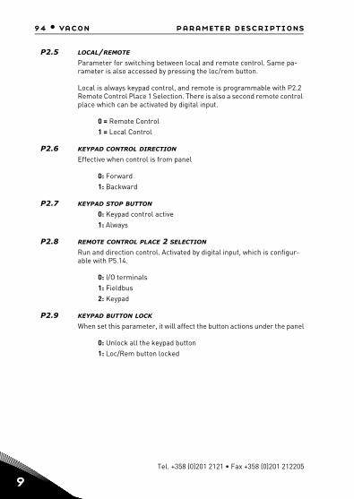
94 • vacon parameter descriptions
9
P2.5 LOCAL/REMOTE
Parameter for switching between local and remote control. Same pa-rameter is also accessed by pressing the loc/rem button.
Local is always keypad control, and remote is programmable with P2.2 Remote Control Place 1 Selection. There is also a second remote control place which can be activated by digital input.
0 = Remote Control1 = Local Control
P2.6 KEYPAD CONTROL DIRECTION
Effective when control is from panel
0: Forward1: Backward
P2.7 KEYPAD STOP BUTTON
0: Keypad control active1: Always
P2.8 REMOTE CONTROL PLACE 2 SELECTION
Run and direction control. Activated by digital input, which is configur-able with P5.14.
0: I/O terminals1: Fieldbus2: Keypad
P2.9 KEYPAD BUTTON LOCK
When set this parameter, it will affect the button actions under the panel
0: Unlock all the keypad button1: Loc/Rem button locked
Tel. +358 (0)201 2121 • Fax +358 (0)201 212205
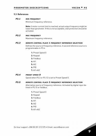
parameter descriptions vacon • 95
9.3 References
P3.1 MIN FREQUENCY
Minimum frequency reference.
Note: if motor current limit is reached, actual output frequency might be lower than parameter. If this is not acceptable, stall protection should be activated.
P3.2 MAX FREQUENCY
Maximum frequency reference.
P3.3 REMOTE CONTROL PLACE 1 FREQUENCY REFERENCE SELECTION
Defines the source of frequency reference. A second reference source is programmable in P3.4.
1: Preset Speed 02: Keypad3: Fieldbus4: AI15: AI26: PID7: AI1+AI2
P3.4 PRESET SPEED 0Speed when P3.3 or P3.12 is set to Preset Speed 0.
P3.5 REMOTE CONTROL PLACE 2 FREQUENCY REFERENCE SELECTION
Alternative source of frequency reference. Activated by digital input de-fined in P5.15 or fieldbus.
1: Preset Speed 02: Keypad3: Fieldbus4: AI15: AI26: PID7: AI1+AI2
24-hour support +358 (0) 201 212 575 • Email: [email protected]
9

96 • vacon parameter descriptions
9
9.4 Ramps and brakes
P4.1 RAMP 1 S-SHAPE
When value is greater than zero, acceleration and deceleration ramps have a S shape.
The parameter is the time needed to reach full acc/dec.
P4.2 ACCELERATION TIME 1The time it takes to change speed from zero frequency to max frequency.
A second acceleration time is available in P4.5.
P4.3 DECELERATION TIME 1The time it takes to change speed from max frequency to zero.
A second deceleration time is available in P4.6.
P4.4 RAMP 2 S-SHAPE
When value is greater than zero, acceleration and deceleration ramps have a S shape.
The parameter is the time needed to reach full acc/dec.
P4.5 ACCELERATION TIME 2
P4.6 DECELERATION TIME 2Ramp 2 is activated through digital input defined in P5.11 or through fieldbus. Automatic selection based on output frequency by parameters P4.13 and P4.14 is also available.
P4.7 FLUX BRAKING
Like other brakes, flux braking tries to stop the motor as quickly as pos-sible. This is done by over magnetizing the motor, which leads to in-creased losses. Kinetic energy is turned into heat in the motor and a quicker deceleration can be used.
An important difference compared to DC-brake is that flux brake can be used while running in U/f control. This means that the motor is still con-trolled and braking can be aborted, where as with DC-brake is the con-trol of motor is lost.
Tel. +358 (0)201 2121 • Fax +358 (0)201 212205

parameter descriptions vacon • 97
Mode Description
0 = Off Not Used
1 = Deceleration Normal mode. Activates flux braking during deceler-ation regardless of load
2 = Chopper
Emulates the behavior of a brake chopper by activating flux braking based on DC-link voltageMinimizes the heating up of the motor in applications with frequent speed changes.
3 = Full mode
Activates flux braking both during deceleration and on generative shock loads at constant speed. Offers the highest performance in demanding appli-cations.
P4.8 FLUX BRAKING CURRENT
Flux brake current reference. Voltage is raised to reach the reference.
P4.9 DC BRAKING CURRENT
DC current injected at start or stop.
P4.10 STOP DC CURRENT TIME
Time for DC current injection at stop.
P4.11 STOP DC CURRENT FREQUENCY
DC current injection starts below this frequency.
P4.12 START DC CURRENT TIME
Time for DC current injection at start. This works as a start magnetiza-tion of the motor, ensuring there is torque when starting to rotate.
P4.13 THRESHOLD FOR ACCELERATION TIME 2Acceleration time 2 is activated when output frequency is higher than the value.
If this parameter is set to 0Hz the functionality will be disabled.
Note: Acceleration time 2 can also at any time be forced active by digital input.
P4.14 THRESHOLD FOR DECELERATION TIME 2.Deceleration time 2 is activated when output frequency is higher than the value.
If this parameter is set to 0Hz the functionality will be disabled.
Note: Deceleration time 2 can also at any time be forced active by digital input.
24-hour support +358 (0) 201 212 575 • Email: [email protected]
9

98 • vacon parameter descriptions
9
9.5 Digital inputs
P5.1 I/O CTRL SIGNAL 1
P5.2 I/O CTRL SIGNAL 2Signals for start and direction in I/O control. Logic is selected with P2.4.
P5.3 REVERSE DIRECTION
Can be used when Ctrl signal 2 does not have the meaning of reverse.
P5.4 EXTERNAL FAULT, CLOSE
Fault is triggered by high digital input.
P5.5 EXTERNAL FAULT, OPEN
Fault is triggered by low digital input.
P5.6 FAULT RESET
Fault reset command is given on rising edge.
P5.7 RUN ENABLE
Motor stops by coasting if the signal is missing.
Note: The drive is not in Ready state when Enable is low.
P5.8 RAMP TIME 2 SELECTION
Ramp 2 is selected by digital input high. Meaning that Acceleration time 2, Deceleration time 2 is taken into use.
P5.9 REMOTE CONTROL PLACE 2Digital input high activates Remote control place 2 (P2.8).
P5.10 REMOTE CONTROL PLACE FREQ REFERENCE 2Digital input high activates Remote control place 2 frequency reference selection (P3.6).
P5.11 PID SETPOINT 2Digital input high activates setpoint 2 (P13.3), when P13.1 = 0.
P5.12 INTER LOCK 1
P5.13 INTER LOCK 2
P5.13 INTER LOCK 3External input confirm if PFC function is active.
Tel. +358 (0)201 2121 • Fax +358 (0)201 212205
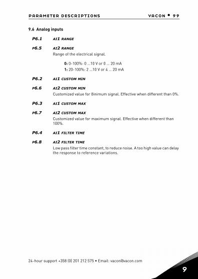
parameter descriptions vacon • 99
9.6 Analog inputs
P6.1 AI1 RANGE
P6.5 AI2 RANGE
Range of the electrical signal.
0: 0-100%: 0 …10 V or 0 … 20 mA1: 20-100%: 2 …10 V or 4 … 20 mA
P6.2 AI1 CUSTOM MIN
P6.6 AI2 CUSTOM MIN
Customized value for 8inimum signal. Effective when different than 0%.
P6.3 AI1 CUSTOM MAX
P6.7 AI2 CUSTOM MAX
Customized value for maximum signal. Effective when different than 100%.
P6.4 AI1 FILTER TIME
P6.8 AI2 FILTER TIME
Low pass filter time constant, to reduce noise. A too high value can delay the response to reference variations.
24-hour support +358 (0) 201 212 575 • Email: [email protected]
9

100 • vacon parameter descriptions
9
9.7 Digital outputs
P7.1 RO1 SIGNAL SELECTION
P7.2 RO2 SIGNAL SELECTION
P7.3 DO1 SIGNAL SELECTION
Function for relays and digital output.
Functions for digital outputs
Value Output active condition
0 = Not used Output not used1 = Ready Drive is ready to run2 = Run Drive is running3 = Fault Drive is in fault state4 = Fault inverted Drive is not in fault state5 = Warning A warning is active6 = Reverse Reverse running7 = At speed Motor speed has reached the reference
8 = Motor regular active Output frequency is over/under the limit set with parameters P12.1 and P12.2
9 = Control pump 1 Pump 1 is active10 = Control pump 2 Pump 2 is active11 = Control pump 3 Pump 3 is active
P7.4 RO1 INVERSION
Inversion of relay state.
P7.5 RO2 INVERSION
Inversion of relay state.
P7.12 AO AS DIGITAL OUTPUT ENABLE
Enable AO as DO function
P7.13 DIGITAL OUT (AO)0 = ready1 = run2 = fault3 = fault inverted
Note: Must active AO as digital output by parameter
Tel. +358 (0)201 2121 • Fax +358 (0)201 212205

parameter descriptions vacon • 101
9.8 Analog outputs
P8.1 ANALOG OUTPUT FUNCTION
Signal coupled to analog output.
Analog output signals
Signal Value corresponding to max output
0 = Test 0% (Not Used) Output always 0%
3 = Output frequency Max frequency (P3.2)
5 = Motor current Motor nominal current
6 = Motor torque Motor nominal torque (absolute value)
10 = PID Output 100%
2 = Frequency reference Max frequency (P3.2)
4 = Motor speed Motor speed at maximum frequency.
7 = Motor power Motor nominal power (absolute value)
8 = Motor Voltage Motor nominal voltage
9 = DC-Link voltage 1000 V
11 = Process Data In1 10000
12 = Process Data In2 10000
13 = Process Data In3 10000
14 = Process Data In4 10000
1 = Test 100%
P8.2 ANALOGUE OUTPUT MINIMUM SIGNAL
0: 0 mA1: 4 mA
P8.3 ANALOGUE OUTPUT SCALING
Scaling factor added to the analog output.
E.g. 200% would mean that when Output frequency is the selected signal, the output would reach 20 mA already at half the maximum frequency.
P8.4 ANALOGUE OUTPUT FILTER TIME
Time constant of low pass filter.
Output always 100%, can be used for testing purposes
24-hour support +358 (0) 201 212 575 • Email: [email protected]
9
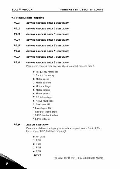
102 • vacon parameter descriptions
9
Tel. +358 (0)201 2121 • Fax +358 (0)201 212205
9.9 Fieldbus data-mapping
P9.1 OUTPUT PROCESS DATA 1 SELECTION
P9.2 OUTPUT PROCESS DATA 2 SELECTION
P9.3 OUTPUT PROCESS DATA 3 SELECTION
P9.4 OUTPUT PROCESS DATA 4 SELECTION
P9.5 OUTPUT PROCESS DATA 5 SELECTION
P9.6 OUTPUT PROCESS DATA 6 SELECTION
P9.7 OUTPUT PROCESS DATA 7 SELECTION
P9.8 OUTPUT PROCESS DATA 8 SELECTION
Parameter couples read only variables to output process data 1.
0: Frequency reference1: Output frequency2: Motor speed3: Motor current4: Motor voltage5: Motor torque6: Motor power7: DC link voltage8: Active fault code9: Analogue AI110: Analogue AI211: Digital inputs state12: PID feedback value13: PID setpoint
P9.9 AUX CW SELECTION
Parameter defines the input process data coupled to Aux Control Word (see chapter 8.3.9 Fieldbus mapping).
0: not used1: PDI12: PDI23: PDI34: PDI45: PDI5

parameter descriptions vacon • 103
9.10 Prohibited frequencies
P10.1 PROHIBIT FREQUENCY RANGE 1: LOW LIMIT
P10.2 PROHIBIT FREQUENCY RANGE 1: HIGH LIMIT
P10.3 PROHIBIT FREQUENCY RANGE 2: LOW LIMIT
P10.4 PROHIBIT FREQUENCY RANGE 2: HIGH LIMIT
Two skip frequency regions are available if there is a need to avoid cer-tain frequencies because of e.g. mechanical resonance. In this case the actual frequency reference sent to the motor control will be kept out of these ranges according to the example below, where one range is in use.
24-hour support +358 (0) 201 212 575 • Email: [email protected]
9
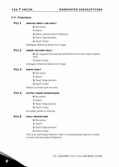
104 • vacon parameter descriptions
9
9.11 Protections
P11.1 ANALOG INPUT LOW FAULT
0: No action1: Alarm2: Alarm, preset alarm frequency3: Fault: Stop function4: Fault: Coast
Analogue reference below min range.
P11.2 UNDER VOLTAGE FAULT
0: No response (no fault generated but drive still stops modula-tion)1: Fault: Coast
Analogue reference below min range.
P11.3 EARTH FAULT
0: No action1: Alarm2: Fault: Stop function3: Fault: Coast
Output currents sum not zero.
P11.4 OUTPUT PHASE SUPERVISION
0: No action1: Alarm2: Fault: Stop function3: Fault: Coast
An output phase is missing.
P11.5 STALL PROTECTION
0: No action1: Alarm2: Fault: Stop function3: Fault: Coast
This is an overload protection. Stall is recognized by maximum motor current and low output frequency.
Tel. +358 (0)201 2121 • Fax +358 (0)201 212205

parameter descriptions vacon • 105
P11.6 UNDERLOAD PROTECTION
0: No action1: Alarm2: Fault: Stop function3: Fault: Coast
Underload is recognized when torque is above the minimum curve de-fined by P13.11 and P13.12, for the programmed time P13.13.
P11.7 MOTOR THERMAL PROTECTION
0: No action1: Alarm2: Fault: Stop function3: Fault: Coast
This is a software protection, based on time integral of current.
NOTE! To comply with UL 508C requirements Motor over-temperature sensing is required at installation if the parameter is set to 0.
P11.8 MOTOR THERMAL PROTECTION: AMBIENT TEMPERATURE
Change if environment is not standard.
P11.9 MOTOR THERMAL PROTECTION: ZERO SPEED COOLING
Set 100% if the motor has independent fan or cooling. Set 30-40% if the fan is on motor shaft.
P11.10 MOTOR THERMAL PROTECTION: THERMAL TIME CONSTANT
Time at nominal current, to reach nominal temperature.
P11.11 STALL CURRENT
P11.12 STALL TIME
P11.13 STALL FREQUENCY
Stall is recognized when the current is over the stall current and the out-put frequency below P13.9, for the time in P13.8.
P11.14 UNDERLOAD: FIELD WEAKENING LOAD
P11.15 UNDERLOAD: ZERO FREQ LOAD
P11.16 UNDERLOAD: TIME LIMIT
Definition of minimum torque at nominal and zero speed zero. Fault con-dition delay.
24-hour support +358 (0) 201 212 575 • Email: [email protected]
9

106 • vacon parameter descriptions
9
P11.17 ANALOG INPUT LOW FAULT DELAY
Delay as filter on fault generation
P11.18 EXTERNAL FAULT
0: No action1: Alarm2: Fault: Stop function3: Fault: Coast
A fault or alarm can be trigged as response to the state of a digital input. The digital input is set with P5.4 or P5.5.
P11.19 FIELDBUS FAULT
0: No action1: Alarm2: Alarm, preset alarm frequency3: Fault: Stop function4: Fault: Coast
P11.20 PRESET ALARM FREQUENCY
This frequency is used as frequency reference when fault response is Alarm+preset Frequency.
P11.21 PARAMETERS EDIT LOCK
0: Edit enabled1: Edit disabled
P11.22 FWD/REV CONFLICT SUPERVISION
If Forward and reverse input at the same time, there will be alarm 55 as the parameter default.
P11.23 LOW FREQUENCY PROTECTION TIME
When the time elapse, and frequency output is less than the frequency Min, then give the fault NO.82
Tel. +358 (0)201 2121 • Fax +358 (0)201 212205
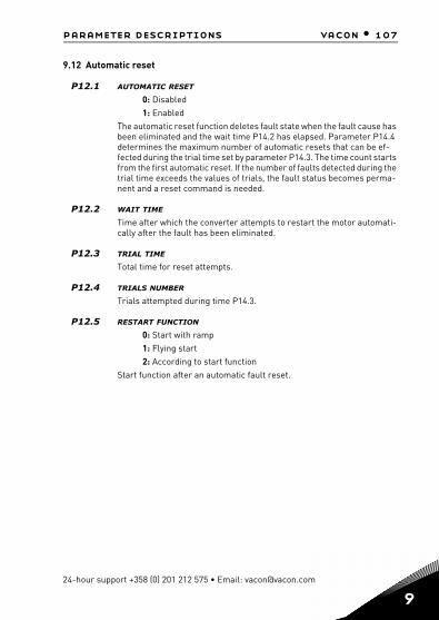
parameter descriptions vacon • 107
9.12 Automatic reset
P12.1 AUTOMATIC RESET
0: Disabled1: Enabled
The automatic reset function deletes fault state when the fault cause has been eliminated and the wait time P14.2 has elapsed. Parameter P14.4 determines the maximum number of automatic resets that can be ef-fected during the trial time set by parameter P14.3. The time count starts from the first automatic reset. If the number of faults detected during the trial time exceeds the values of trials, the fault status becomes perma-nent and a reset command is needed.
P12.2 WAIT TIME
Time after which the converter attempts to restart the motor automati-cally after the fault has been eliminated.
P12.3 TRIAL TIME
Total time for reset attempts.
P12.4 TRIALS NUMBER
Trials attempted during time P14.3.
P12.5 RESTART FUNCTION
0: Start with ramp1: Flying start2: According to start function
Start function after an automatic fault reset.
24-hour support +358 (0) 201 212 575 • Email: [email protected]
9
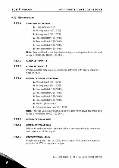
108 • vacon parameter descriptions
9
9.13 PID controller
P13.1 SETPOINT SELECTION
0: Fixed setpoint 1-21: Analog input 1 (0-100%)2: Analog input 2 (0-100%)3: ProcessDataIn1 (0-100%)4: ProcessDataIn2 (0-100%)5: ProcessDataIn3 (0-100%)6: ProcessDataIn4 (0-100%)
Note: ProcessDataIns are handled as integers having two decimals and range 0 (0.00%) to 10000 (100.00%).
P13.2 FIXED SETPOINT 1
P13.3 FIXED SETPOINT 2Programmable setpoints. Setpoint 2 is activated with digital input de-fined in P5.16.
P13.4 FEEDBACK VALUE SELECTION
0: Analog input 1 (0-100%)1: Analog input 2 (0-100%)2: ProcessDataIn1 (0-100%)3: ProcessDataIn2 (0-100%)4: ProcessDataIn3 (0-100%)5: ProcessDataIn4 (0-100%)6: AI2-AI1 (differential)7: Pulse train/encoder (0-100%)
Note: Process DataIns are handled as integers having two decimals and range 0 (0.00%) to 10000 (100.00%).
P13.5 FEEDBACK VALUE MIN
P13.6 FEEDBACK VALUE MAX
Minimum and maximum feedback values, corresponding to minimum and maximum of the signal.
P13.7 PROPORTIONAL GAIN
Proportional gain. If set to 100%, a variation of 10% on error causes a variation of 10% on regulator output.
Tel. +358 (0)201 2121 • Fax +358 (0)201 212205

parameter descriptions vacon • 109
P13.8 INTEGRAL TIME
Integral time constant. If set to 1s, a variation of 10% on error will cause a variation of 10% on regulator output after 1s.
P13.9 DERIVATIVE TIME
Derivative time. If set to 1s, a variation of 10% in 1s on error causes a var-iation of 10% on regulator output.
P13.10 ERROR INVERSION
0: direct control. Frequency increased if setpoint > feedback1: inverted control. Frequency increased if setpoint < feedback
P13.11 PROCESS DISPLAY SOURCE
Monitor V4.5 can show a process value, proportional to a variable meas-ured by the drive. Source variables are:
0: PID feedback value (max: 100%)1: output frequency (max: fmax)2: motor speed (max: nmax)3: motor torque (max: Tnom)4: motor power (max: Pnom)5: motor current (max: Inom)
P13.12 PROCESS DISPLAY DECIMAL DIGITS
Number of decimals shown on monitor V4.5 and also on parameter P15.20.
P13.13 PROCESS DISPLAY MIN VALUE
P13.14 PROCESS DISPLAY MAX VALUE
Value shown on V4.5 when source variable is at between minimum max-imum. Proportionality is kept if source overtakes between minimum and maximum.
24-hour support +358 (0) 201 212 575 • Email: [email protected]
9

110 • vacon parameter descriptions
9
9.14 PFCThe Auto-change function allows the starting and stopping order of drives controlled by the pump and fan automatics to be changed at de-sired intervals. The drive controlled by frequency converter can also be included in the automatic changing and locking sequence. The Auto-change function makes it possible to equalize the run times of the mo-tors and to prevent e.g. pump stalls due to too long running breaks.
• Apply the Auto-change function with parameter 14.1, Auto-change Mode.
• The auto-change takes place when the time set with parameter 14.5, Auto-change interval, has expired and the capacity used is below the level defined with parameter 14.7, Auto-change fre-quency limit.
• The running drives are stopped and re-started according to the new order.
• External contactors controlled through the relay outputs of the frequency converter connect the drives to the frequency con-verter or to the mains. If the motor controlled by the frequency converter is included in the auto-change sequence, it is always controlled through the relay output activated first. The other re-lays activated later control the auxiliary drives.
P14.1 AUTO-CHANGE MODE
Auto-change is used to make pump wear more uniform.
0 = No auto-change. Connection/disconnection order of pumps will always remain the same and the controller will regulate the speed of the first pump.1 = Auxiliary auto-change without interlocks. Controller regulates the speed of the first pump and auxiliary pumps alternate (connecting and disconnecting).2 = Total auto-change without interlocks. Controller alternates the regulation of all pump speeds in the sys-tem.3 = Auxilliary auto-change with interlocks. Controller regulates the speed of the first pump and auxiliary pumps alternate (connecting anddisconnecting). Interlocks are required to connect pumps.4 = Total auto-change with interlocks. Controller alternates regulation of the speed of all the pumps in the system. Interlocks are required to connect pumps.
Tel. +358 (0)201 2121 • Fax +358 (0)201 212205
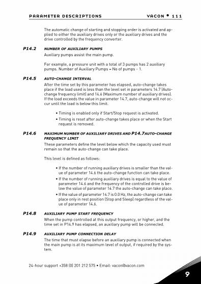
parameter descriptions vacon • 111
24-hour support +358 (0) 201 212 575 • Email: [email protected]
The automatic change of starting and stopping order is activated and ap-plied to either the auxiliary drives only or the auxiliary drives and the drive controlled by the frequency converter.
P14.2 NUMBER OF AUXILIARY PUMPS
Auxiliary pumps assist the main pump.
For example, a pressure unit with a total of 3 pumps has 2 auxiliary pumps. Number of Auxiliary Pumps = No of pumps - 1.
P14.5 AUTO-CHANGE INTERVAL
After the time set by this parameter has elapsed, auto-change takes place if the load used is less than the level set in parameters 14.7 (Auto-change frequency limit) and 14.6 (Maximum number of auxiliary drives). If the load exceeds the value in parameter 14.7, auto-change will not oc-cur until the load is below this limit.
• Timing is enabled only if Start/Stop request is activated.• Timing is reset after auto-change takes place or when the Start
request is removed.
P14.6 MAXIMUM NUMBER OF AUXILIARY DRIVES AND P14.7AUTO-CHANGE FREQUENCY LIMIT
These parameters define the level below which the capacity used must remain so that the auto-change can take place.
This level is defined as follows:
• If the number of running auxiliary drives is smaller than the val-ue of parameter 14.6 the auto-change function can take place.
• If the number of running auxiliary drives is equal to the value of parameter 14.6 and the frequency of the controlled drive is be-low the value of parameter 14.7 the auto-change can take place.
• If the value of parameter 14.7 is 0.0 Hz, the auto-change can take place only in rest position (Stop and Sleep) regardless of the val-ue of parameter 14.6.
P14.8 AUXILIARY PUMP START FREQUENCY
When the pump controlled at this output frequency, or higher, and the time set in P14.9 has elapsed, an auxiliary pump will be connected.
P14.9 AUXILIARY PUMP CONNECTION DELAY
The time that must elapse before an auxiliary pump is connected when the main pump is at its maximum level of output, if required by the sys-tem.
9
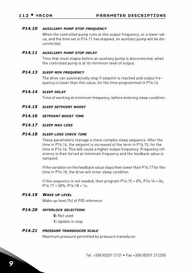
112 • vacon parameter descriptions
9
P14.10 AUXILIARY PUMP STOP FREQUENCY
When the controlled pump runs at this output frequency, or a lower val-ue, and the time set in P14.11 has elapsed, an auxiliary pump will be dis-connected.
P14.11 AUXILIARY PUMP STOP DELAY
Time that must elapse before an auxiliary pump is disconnected, when the controlled pump is at its minimum level of output.
P14.13 SLEEP MIN FREQUENCY
The drive can automatically stop if setpoint is reached and output fre-quency is lower than this value, for the time programmed in P14.14.
P14.14 SLEEP DELAY
Time of working at minimum frequency, before entering sleep condition.
P14.15 SLEEP SETPOINT BOOST
P14.16 SETPOINT BOOST TIME
P14.17 SLEEP MAX LOSS
P14.18 SLEEP LOSS CHECK TIME
These parameters manage a more complex sleep sequence. After the time in P14.14, the setpoint is increased of the term in P14.15, for the time in P14.16. This will cause a higher output frequency. Frequency ref-erence is then forced at minimum frequency and the feedback value is sampled.
If the variation on the feedback value stays then lower than P14.17 for the time in P14.18, the drive will enter sleep condition.
If this sequence is not needed, then program P14.15 = 0%, P14.16 = 0s, P14.17 = 50%, P14.18 = 1s.
P14.19 WAKE UP LEVEL
Wake up level (%) of PID reference
P14.20 INTERLOCK SELECTION:0: Not used1: Update in stop
P14.21 PRESSURE TRANSDUCER SCALE
Maximum pressure permitted by pressure transducer.
Tel. +358 (0)201 2121 • Fax +358 (0)201 212205

parameter descriptions vacon • 113
9.15 Application setting
P15.2 PARAMETER CONCEAL
0: All parameters visible1: Only quick setup parameter group visible
24-hour support +358 (0) 201 212 575 • Email: [email protected]
9
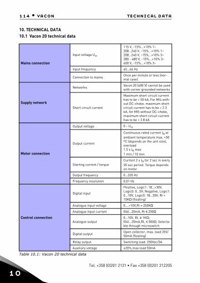
114 • vacon technical data
1
Tel. +358 (0)201 2121 • Fax +358 (0)201 212205
10. TECHNICAL DATA10.1 Vacon 20 technical data
Mains connection
Input voltage Uin
115 V, -15%...+10% 1~208…240 V, -15%...+10% 1~208…240 V, -15%...+10% 3~380 - 480 V, -15%...+10% 3~600 V, -15%...+10% 3~
Input frequency 45…66 Hz
Connection to mains Once per minute or less (nor-mal case)
Supply network
Networks Vacon 20 (400 V) cannot be used with corner grounded networks
Short circuit current
Maximum short circuit current has to be < 50 kA, For MI4 with-out DC-choke, maximum short circuit current has to be < 2.3 kA, for MI5 without DC-choke, maximum short circuit current has to be < 3.8 kA
Motor connection
Output voltage 0 - Uin
Output current
Continuous rated current IN at ambient temperature max. +50 ºC (depends on the unit size), overload 1.5 x IN max1 min / 10 min
Starting current / torqueCurrent 2 x IN for 2 sec in every 20 sec period. Torque depends on motor
Output frequency 0…320 Hz
Frequency resolution 0,01 Hz
Control connection
Digital input
Positive, Logic1: 18…+30V, Logic0: 0…5V; Negative, Logic1: 0…10V, Logic0: 18…30V; Ri = 10KΩ (floating)
Analogue input voltage 0….+10V,Ri = 250KΩ
Analogue input current 0(4)…20mA, Ri ≤ 250Ω
Analogue output0…10V, RL ≥ 1KΩ; 0(4)…20mA,RL ≤ 500Ω, Selecta-ble through microswitch
Digital output Open collector, max. load 35V/50mA (floating)
Relay output Switching load: 250Vac/3A
Auxiliary voltage ±20%,max.load 50mA
Table 10.1: Vacon 20 technical data
0
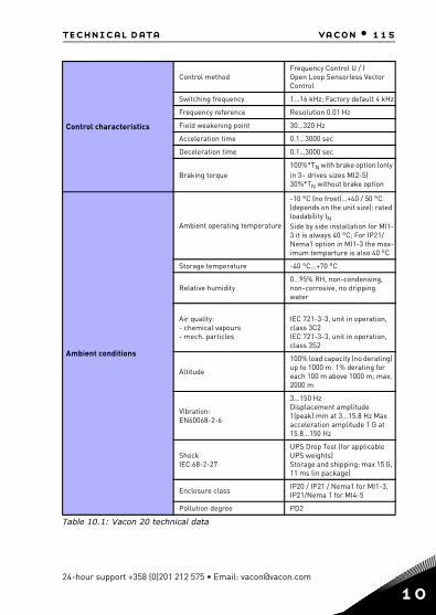
technical data vacon • 115
Control characteristics
Control methodFrequency Control U / fOpen Loop Sensorless Vector Control
Switching frequency 1...16 kHz; Factory default 4 kHz
Frequency reference Resolution 0.01 Hz
Field weakening point 30…320 Hz
Acceleration time 0.1…3000 sec
Deceleration time 0.1…3000 sec
Braking torque100%*TN with brake option (only in 3~ drives sizes MI2-5) 30%*TN without brake option
Ambient conditions
Ambient operating temperature
-10 °C (no frost)…+40 / 50 °C (depends on the unit size): rated loadability INSide by side installation for MI1-3 it is always 40 °C; For IP21/Nema1 option in MI1-3 the max-imum temparture is also 40 °C
Storage temperature -40 °C…+70 °C
Relative humidity0…95% RH, non-condensing, non-corrosive, no dripping water
Air quality:- chemical vapours- mech. particles
IEC 721-3-3, unit in operation, class 3C2IEC 721-3-3, unit in operation, class 3S2
Altitude
100% load capacity (no derating) up to 1000 m. 1% derating for each 100 m above 1000 m; max. 2000 m
Vibration:EN60068-2-6
3...150 HzDisplacement amplitude 1(peak) mm at 3...15.8 Hz Max acceleration amplitude 1 G at 15.8...150 Hz
ShockIEC 68-2-27
UPS Drop Test (for applicable UPS weights)Storage and shipping: max 15 G, 11 ms (in package)
Enclosure class IP20 / IP21 / Nema1 for MI1-3, IP21/Nema 1 for MI4-5
Pollution degree PD2
Table 10.1: Vacon 20 technical data
24-hour support +358 (0)201 212 575 • Email: [email protected]
10
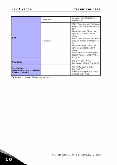
116 • vacon technical data
1
EMC
Immunity Complies with EN50082-1, -2, EN61800-3
Emissions
230V : Complies with EMC cate-gory C2; With an internal RFI fil-terMI4&5 complies C2 with an optional DC choke and CM choke400V: Complies with EMC cate-gory C2; With an internal RFI fil-terMI4&5 complies C2 with an optional DC choke and CM chokeBoth: No EMC emission pro-tection (Vacon level N): Without RFI filter
Standards For EMC: EN61800-3, For safety: UL508C, EN61800-5
Certificatesand manufacturer’s declara-tions of conformity
For safety: CE, UL, cUL, For EMC: CE(see unit nameplate for more detailed approvals)
Table 10.1: Vacon 20 technical data
Tel. +358 (0)201 2121 • Fax +358 (0)201 212205
0
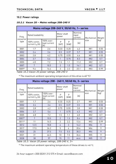
technical data vacon • 117
10.2 Power ratings
10.2.1 Vacon 20 – Mains voltage 208-240 V
* The maximum ambient operating temperature of these drives is +40 °C.
Mains voltage 208-240 V, 50/60 Hz, 1~ series
Freq. converter
type
Rated loadability Motor shaft power
Nominal inputcurrent Mechanical
sizeWeight (kg)
100% contin. current IN [A]
150% over-load current [A]
P[HP]
P[KW] [A]
0001 1.7 2.6 0.33 0.25 4.2 MI1 0.55
0002 2.4 3.6 0.5 0.37 5.7 MI1 0.55
0003 2.8 4.2 0.75 0.55 6.6 MI1 0.55
0004 3.7 5.6 1 0.75 8.3 MI2 0.7
0005 4.8 7.2 1.5 1.1 11.2 MI2 0.7
0007 7 10.5 2 1.5 14.1 MI2 0.7
0009* 9.6 14.4 3 2.2 22.1 MI3 0.99Table 10.2:Vacon 20 power ratings, 208-240 V
* The maximum ambient operating temperature of this drive is 40 °C!
Mains voltage 208 - 240 V, 50/60 Hz, 3~ series
Freq. converter
type
Rated loadability Motor shaft power
Nominal input current Mechanical
size Weight (kg)
100% contin. current IN [A]
150% over-load current[A]
P[HP]
P[KW] [A]
0001 1.7 2.6 0.33 0.25 2.7 MI1 0.55
0002 2.4 3.6 0.5 0.37 3.5 MI1 0.55
0003 2.8 4.2 0.75 0.55 3.8 MI1 0.55
0004 3.7 5.6 1 0.75 4.3 MI2 0.7
0005 4.8 7.2 1.5 1.1 6.8 MI2 0.7
0007* 7 10.5 2 1.5 8.4 MI2 0.7
0011* 11 16.5 3 2.2 13.4 MI3 0.99
0012 12.5 18.8 4 3 14.2 MI4 9
0017 17.5 26.3 5 4 20.6 MI4 9
0025 25 37.5 7.5 5.5 30.3 MI4 9
0031 31 46.5 10 7.5 36.6 MI5 11
0038 38 57 15 11 44.6 MI5 11Table 10.3: Vacon 20 power ratings, 208-240 V, 3~
24-hour support +358 (0)201 212 575 • Email: [email protected]
10
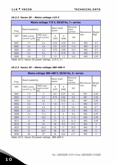
118 • vacon technical data
1
10.2.2 Vacon 20 – Mains voltage 115 V
10.2.3 Vacon 20 – Mains voltage 380-480 V
Mains voltage 115 V, 50/60 Hz, 1~ series
Freq. converter
type
Rated loadability Motor shaft power
Nominal input current Mechanical
sizeWeight (Kg)
100% contin. current IN [A]
150% over-load current[A]
P[HP]
P[KW] [A]
0001 1.7 2.6 0.33 0.25 9.2 MI2 0.7
0002 2.4 3.6 0.5 0.37 11.6 MI2 0.7
0003 2.8 4.2 0.75 0.55 12.4 MI2 0.7
0004 3.7 5.6 1 0.75 15 MI2 0.7
0005 4.8 7.2 1.5 1.1 16.5 MI3 0.99Table 10.4: Vacon 20 power ratings, 115 V, 1~
Mains voltage 380-480 V, 50/60 Hz, 3~ series
Freq. converter
type
Rated loadability Motor shaft power
Nominal input current Mechanical
size Weight (kg)
100% contin. current IN [A]
150% over-load current [A]
P[HP]
P[KW] [A]
0001 1.3 2 0.5 0.37 2.2 MI1 0.55
0002 1.9 2.9 0.75 0.55 2.8 MI1 0.55
0003 2.4 3.6 1 0.75 3.2 MI1 0.55
0004 3.3 5 1.5 1.1 4 MI2 0.7
0005 4.3 6.5 2 1.5 5.6 MI2 0.7
0006 5.6 8.4 3 2.2 7.3 MI2 0.7
0008 7.6 11.4 4 3 9.6 MI3 0,99
0009 9 13.5 5 4 11.5 MI3 0.99
0012 12 18 7.5 5.5 14.,9 MI3 0.99
0016 16 24 10 7.5 17.1 MI4 9
0023 23 34.5 15 11 25.5 MI4 9
0031 31 46.5 20 15 33 MI5 11
0038 38 57 25 18.5 41.7 MI5 11Table 10.5: Vacon 20 power ratings, 380-480 V
Tel. +358 (0)201 2121 • Fax +358 (0)201 212205
0

technical data vacon • 119
10.2.4 Vacon 20 – Mains voltage 600 V
Note 1: The input currents are calculated values with 100 kVA line transformer supply.
Note 2: The mechanical dimensions of the units are given in Chapter 3.1.1.
10.3 Brake resistors
Vacon 20 type Minimum brak-ing resistance
Resistor type code (from Vacon NX family)
Light duty Heavy duty Resistance
MI2 204-240V,3~ 50 Ohm - - -
MI2 380-480V,3~ 118 Ohm - - -
MI3 204-240V, 3~ 31 Ohm - - -
MI3 380-480V, 3~ 55 Ohm BRR-0022-LD-5 BRR-0022-HD-5 63 Ohm
MI3 600V, 3~ 100 Ohm BRR-0013-LD-6 BRR-0013-HD-6 100 Ohm
MI4 204-240V, 3~ 14 Ohm BRR-0025-LD-2 BRR-0025-HD-2 30 Ohm
MI4 380-480V, 3~ 28 Ohm BRR-0031-LD-5 BRR-0031-HD-5 42 Ohm
MI5 204-240V, 3~ 9 Ohm BRR-0031-LD-2 BRR-0031-HD-2 20 Ohm
MI5 380-480V, 3~ 17 Ohm BRR-0045-LD-5 BRR-0045-HD-5 21 Ohm
Note! For MI2 and MI3, only 3-phase units are equipped with brake chopper.
For further information on brake resistors, please download Vacon NX Brake Resis-tor Manual (UD00971C) on http://www.vacon.com / Support & Downloads
Mains voltage 600 V, 50/60 Hz, 3~ series
Fre-quency
converter type
Rated loadability Motor shaft power
Nominal input current Mechanical
size Weight (kg)
100% contin. current IN [A]
150% over-load current [A]
P[HP]
P[KW] [A]
0002 1,7 2,6 1 0,75 2 MI3 0,99
0003 2,7 4,2 2 1,5 3,6 MI3 0,99
0004 3,9 5,9 3 2,2 5 MI3 0,99
0006 6,1 9,2 5 3.7 7,6 MI3 0,99
0009 9 13,5 7.5 5,5 10,4 MI3 0,99Table 10.6: Vacon 20 power ratings, 600 V
24-hour support +358 (0)201 212 575 • Email: [email protected]
10

Rev. B
Document ID:
Manual authoring:[email protected]
Vacon Suzhou Drives Co. Ltd.No. 71 Xinqing RoadSuzhou Industrial ParkSuzhou, Jiangsu Province,P.R. China, 215123
Subject to change without prior notice
© 2013 Vacon Plc.
Find your nearest Vacon office on the Internet at:
www.vacon.com