v2f™ anterior fixation system surgical technique · turn clockwise to advance the pin into the...
TRANSCRIPT

Solutions by the people of Zimmer Spine.zimmerspine.com
V2FTM
Anterior Fixation System
Surgical Technique

The V2F Anterior Fixation System has been designed for use in the treatment of
thoracolumbar burst fractures, tumors, disc degeneration and other unstable
pathologies of the anterior spine. The V2F System consists of a wide range of plates
and screws designed to accommodate the varying anatomy of the thoracolumbar
spine. The system provides surgeons the ability to rigidly fixate the screw to the
plate using a Fixed Cap Screw or semi-constrain the screw to the plate using a
Variable Cap Screw. The combination of features, technique options and the wide
range of instruments and implants make the Zimmer V2F Anterior Fixation System
one of the most versatile and comprehensive systems on the market.
Traditional approach. New Technique.From the people of Zimmer Spine.

Indications/Contraindications 1
V2F Implants 3
V2F Instruments 4
Surgical Technique 7
V2F Kit Contents 36
Warnings, Precautions and Adverse Effects 40
Warranty 43
Table of Contents
1
Indications
The V2F Anterior Fixation System is indicated for use via the lateral or anterolateral surgical approach
in the treatment of thoracic and thoracolumbar (T1-L5) spine instability as a result of fracture
(including dislocation and subluxation), tumor, degenerative disc disease (defined as back pain
of discogenic origin with degeneration of the disc confirmed by patient history and radiographic
studies), scoliosis, kyphosis, lordosis, spinal stenosis, or a failed previous spine surgery.
Indications/Contraindications
2
Contraindications
Contraindications for use of the V2F Anterior Fixation System include:
• Use in the cervical spine
• Active systemic or local infection
• Local inflammation, with or without fever or leukocytosis
• Pregnancy
• Diseases or conditions other than those specifically described in the Indications section
• Use in the posterior elements (pedicles) of the cervical, thoracic, or lumbar vertebrae
• Where attempted correction exceeds the limits of physiological conditions
• Uncooperative patient or patient with neurologic disorders rendering the patient incapable of
following instructions
• Metabolic disorders that may impair bone formation
• Inadequate bone stock to support the device
• Inability to restrict high activity level
• Suspected or documented metal allergy or intolerance
• Any medical or surgical condition that would preclude the potential benefit of spinal implant
surgery or prevent secure component fixation that has the potential to decrease the useful
life of the device, such as the presence of tumors or congenital abnormalities, elevation of
sedimentation rate unexplained by other diseases, elevation of white blood count (WBC), or a
marked left shift in the WBC differential count
• Any patient with inadequate tissue coverage over the operative site, or inadequate bone stock or
bone quality such as in the sacrum
• Any time implant utilization would interfere with anatomical structures or expected physiological
performance
• Obesity
• Poor prognosis for good wound healing (e.g. decubitis ulcer, end-stage diabetes, severe protein
deficiency and/or malnutrition)

3
V2F Implants
Cap Screws Fixed (Gold) 07.01660.001Variable (Green) 07.01661.001
Thoracolumbar Plates 07.01657.001-021 30-130mm in 5mm increments
Screws 6mm (Aqua) 07.01658.001-0077mm (Magenta) 07.01659.001-00730-60mm in 5mm increments

4
V2F Instruments
Torque Wrench 07.01669.001
Used in conjunction with the Cap Screw Driver for final tightening of Cap Screws, ¼ in. square drive. 50 in/lbs.
Ratcheting T-Handle 07.01736.001
Connects to Drills, Tap, Screw Driver, and Cap Screw Driver, ¼ in. square drive.
Ratcheting Inline Handle 07.01667.001
Connects to Drills, Tap, Screw Driver and Cap Screw Driver, ¼ in. square drive.
Plate Holder 07.01664.001
Used alone or in conjunction with Plate Holder Handle to assist with initial plate placement.
Screw Driver 07.01670.001
Used to drive screw and also tighten or loosen ATO Guides to plate, incorporates retention spring technology to hold screw, 4.5mm Hex.
Cap Screw Driver 07.01670.001
Used to insert Cap Screw incorporates retention feature to hold Cap Screws, T25 – Hexalobe.
6.0mm Tap 07.01674.001
Optional instrument for tapping screw hole prior to screw placement. Length is 61mm, laser marked lines on distal end represent 10mm increments.
60mm Drill 07.01671.002
Used for drilling screw hole prior to screw placement. Length is 60mm, laser marked lines on distal end represent 10mm increments.

5
25mm Drill 07.01671.001
Used for drilling screw hole prior to screw placement. Length is 25mm, laser marked lines on distal end represent 10mm increments.
ATO Guide Handle 07.01665.001
Connects to ATO Holder, can be attached in 6 different positions to facilitate screw prep and placement through ATO Guides.
All-Through-One (ATO) Holder 07.01735.001
Connects to ATO Guide, can be used to attach ATO Guide to plate in-situ or prior to plate placement, can also be used as plate holder in conjunction with ATO Guide Handle.
All-Through-One (ATO) Guides 07.01662.001 (superior)07.01663.001 (inferior)
All-Though-One Guides attach to plates and provide controlled trajectory for screw preparation and placement.
Awl 07.01676.001
Awl can be used through ATO Guides or in a freehand approach. Can also be used as temporary fixation device when through ATO Guides. Awl length is 25mm.
Compressor 07.01681.001
Compressor used with compressor tips and compression pin to provide compression on a VBR device.

6
Compression Tips 07.01682.001 - Compression Tip Superior07.01683.001 – Short Compression Tip Inferior07.01685.001 - Medium Compression Tip Inferior07.01687.001 – Large Compression Tip Inferior
Compression Tips are used in conjunction with the compressor to provide compression on a VBR device.
Templating Caliper 07.01666.001
Assists in determining the appropriate length plate. Note: Plate length is measured from center of the closest holes on the plate.
Temporary Fixation Pin 07.01678.001 (Single Use)
Used through the screw hole in the plate to provide temporary fixation.
Compression Pin 07.01679.001 (Single Use)
Used adjacent to the plate to provide anchor for compression technique.
Temporary Fixation Pin Inserter 07.01680.001
Attaches to Ratcheting Inline or T-Handle to and used to insert Temporary fixation pin or Compression Pin.
Depth Gauge 07.01673.001
Used to measure depth of prepared hole and select ap-propriate length screw.

7
Standard Technique
CorpectomyComplete corpectomy procedure. Remove any
osteophytes or boney protrusions that prevent the
plate from sitting flush on the vertebral body.
Step 1
Plate Selection Use calipers to determine plate length.
Step 2
Plate length
The labeled plate length is measured from the center
of the screw holes closest to endplates.
8
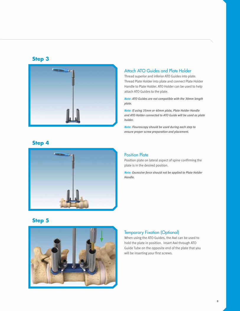
Position Plate Position plate on lateral aspect of spine confirming the
plate is in the desired position.
Note: Excessive force should not be applied to Plate Holder
Handle.
Temporary Fixation (Optional)When using the ATO Guides, the Awl can be used to
hold the plate in position. Insert Awl through ATO
Guide Tube on the opposite end of the plate that you
will be inserting your first screws.
Step 4
Step 5
Attach ATO Guides and Plate Holder Thread superior and inferior ATO Guides into plate.
Thread Plate Holder into plate and connect Plate Holder
Handle to Plate Holder. ATO Holder can be used to help
attach ATO Guides to the plate.
Note: ATO Guides are not compatible with the 30mm length
plate.
Note: If using 35mm or 40mm plate, Plate Holder Handle
and ATO Holder connected to ATO Guide will be used as plate
holder.
Note: Flouroscopy should be used during each step to
ensure proper screw preparation and placement.
Step 3

9
Option 1: The Bone Awl can be used to penetrate the
cortex of the vertebral body and create a pilot hole for
the screw. The Awl has a positive stop at 25mm.
Note: When using the Bone Awl, caution should be taken to
ensure that the spinal canal is not violated. Fluoroscopy is
recommended during this step.
Step 6
Positive Stop
Depth Markings
Positive Stop
Depth Markings
Positive Stop
Prepare Bone Screw HoleThere are two options that can be used for preparing the screw hole.
Option 2: A 25mm and 60mm Drill is provided as an
alternative for preparing a screw hole. To use drill,
attach Ratcheting Inline Handle, advance clockwise
until appropriate drill depth is reached (confirm drill
depth using flouro). Laser marked lines on the Drills
identify the depth of drill engagement in bone.
An optional 5.5mm Tap is provided if needed. To
use Tap, attach Ratcheting Inline Handle, advance
clockwise until appropriate depth is reached (confirm
depth using flouro). Laser marked lines on the Tap
identify the depth of Tap engagement in bone. Rotate
counter-clockwise to remove.
Note: When using the Drill or Tap caution should be taken to
ensure that the spinal canal is not violated. Fluoroscopy is
recommended during each of these steps.
Note: The Drills have a positive stop at 25mm and 60mm.
The positive stop for the Tap is 61mm.

10
Bone Screw Selection Screw length should be based off depth of drilling or
tapping. If it’s desired to use Depth Gauge to confirm
screw length, remove ATO guide to use Depth Gauge.
Depth Gauge may need to be pushed through the
cancellous bone to the desired depth. The lines on
the Depth Gauge will represent the appropriate screw
length.
Step 7
Screw length
6mm Screw
7mm ScrewThe V2F Anterior Fixation System offers dual-lead
cortical/cancellous screws available in 6.0mm and
7.0mm diameters. Choose the appropriate length
and diameter screw. Screw lengths are measured from
the base of the screw head to the tip of the screw.

11
Attach screw onto Screw Driver and insert into prepared
screw hole. While ensuring Screw Driver is fully seated
in screw, advance until line on Screw Driver meets top
of ATO Guide. This position represents provisionally
tightened screws. Remove Screw Driver. Repeat steps
6-8 for adjacent screw hole.
Bone Screw InsertionConnect the Screw Driver to either the Inline or
Ratcheting T-Handle.
Step 8
Bone Screw InsertionIf Awl was used to fixate plate, remove and follow steps
7-8 for screw placement.
Step 9

12
Step 10
Bone Screw InsertionFollow steps 6-8 for screw placement in the remaining
holes.
Step 11
Remove Plate Holder and ATO Guides Remove Plate holder, then insert hex tip of ATO Holder
into ATO Guide. Turn sleeve clockwise to engage
threaded post on ATO Guide. Rotate top of ATO Holder
counter clockwise to remove ATO Guide from plate.

13
Final Tighten Bone Screws Fully seat Screw Driver in screw and final tighten all
screws in a star pattern to ensure plate seats evenly
on vertebral bodies.
Note: Bone Screws must be fully seated to ensure Cap
Screws engage appropriately.
Step 12
Insertion of Locking CapsSelect either the Fixed (Gold) or Variable (Green) Cap
Screw. The Fixed Cap Screw will lock the screw in a
fixed position relative to the plate. The Variable Cap
Screw will accommodate controlled movement of the
screw relative to the plate, allowing for load sharing.
Attach the appropriate Cap Screw to the Cap Screw
Driver and insert into one of the positions on plate.
Advance until provisionally tight, repeat for remaining
Cap Screws
Note: Cap Screw should engage plate without resistance;
any resistance might signal Cap Screw cross threading with
plate.
Step 13
Final Tightening Cap ScrewsAttach Cap Screw Driver to Torque Limiting
T-Handle. Fully seat Cap Screw Driver into one of
the provisionally tightened Cap Screws, and turn
clockwise until Torque Limiting T-Handle snaps.
Repeat step for remaining Cap Screws.
Note: 50 in lb. Torque Wrench must be used for final
tightening of Cap Screws
Step 14
14
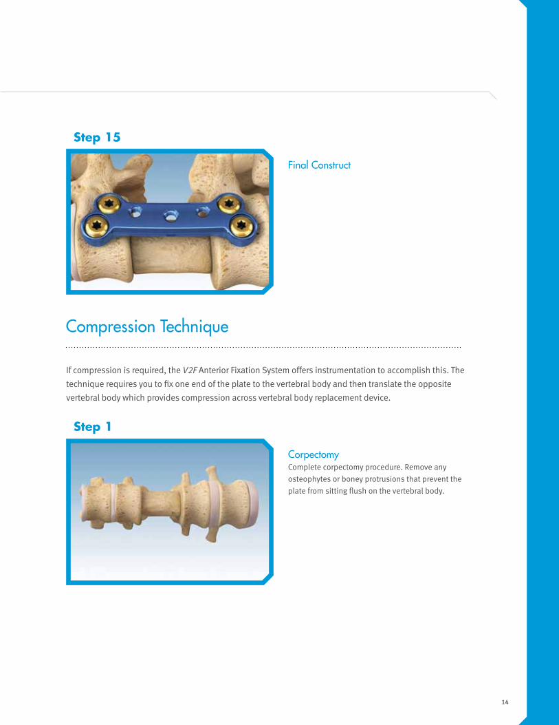
Final Construct
Step 15
CorpectomyComplete corpectomy procedure. Remove any
osteophytes or boney protrusions that prevent the
plate from sitting flush on the vertebral body.
Step 1
Compression Technique
If compression is required, the V2F Anterior Fixation System offers instrumentation to accomplish this. The
technique requires you to fix one end of the plate to the vertebral body and then translate the opposite
vertebral body which provides compression across vertebral body replacement device.

15
Plate SelectionUse calipers to determine plate length.
Step 2
Plate length
Attach ATO Guides and Plate HolderThread superior and inferior ATO Guides into plate.
Thread Plate Holder into plate and connect Plate
Holder Handle to Plate Holder. ATO Holder can be
used to help attach ATO Guides to the plate.
Note: ATO Guides are not compatible with the 30mm length
plate.
Note: If using 35mm or 40mm plate, Plate Holder Handle
and ATO Holder connected to ATO Guide will be used as plate
holder.
Note: Fluoroscopy should be used during each step to
ensure proper screw preparation and placement.
Step 3
The labeled plate length is measured from the center
of the screw holes closest to endplates.

16
Position PlatePosition plate on lateral aspect of spine confirming
the plate is in the desired position.
Note: Excessive force should not be applied to Plate Holder
Handle.
Step 4
Temporary Fixation (Optional)When using the ATO Guides the Awl can be used to
hold the plate in position. When using compression
technique, insert Awl through ATO Guide Tube on the
end of the plate that you will be inserting your first
screws.
Note: Awl should not be used on opposite end of plate that
you are inserting screws; this could cause issues when
trying to prepare screw holes after compression has been
applied.
Step 5

17
Option 1: The Bone Awl can be used to penetrate the
cortex of the vertebral body and create a pilot hole for
the screw. The Awl has a positive stop at 25mm.
Note: When using the Bone Awl, caution should be taken to
ensure that the spinal canal is not violated. Fluoroscopy is
recommended during this step.threading with plate.
Positive Stop
Depth Markings
Positive Stop
Depth Markings
Positive Stop
Step 6
Prepare Inferior Bone Screw HolesThere are two options that can be used for preparing the screw hole.
Option 2: A 25mm and 60mm drill is provided as an
alternative for preparing a screw hole. To use Drill,
attach Ratcheting Inline Handle, advance clockwise
until appropriate drill depth is reached (confirm drill
depth using flouro). Laser marked lines on the Drills
identify the depth of drill engagement in bone.
An optional 5.5mm Tap is provided if needed. To
use Tap, attach Ratcheting Inline Handle, advance
clockwise until appropriate depth is reached (confirm
depth using flouro). Laser marked lines on the Tap
identify the depth of Tap engagement in bone. Rotate
counter-clockwise to remove.
Note: When using the Drill or Tap caution should be taken to
ensure that the spinal canal is not violated. Fluoroscopy is
recommended during each of these steps.
Note: The Drills have a positive stop at 25mm and 60mm.
The positive stop for the Tap is 61mm.
18
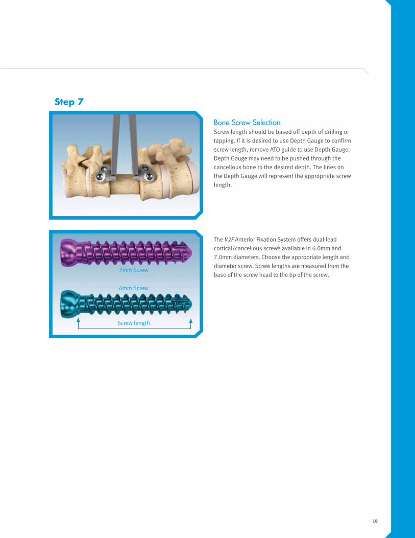
Bone Screw SelectionScrew length should be based off depth of drilling or
tapping. If it is desired to use Depth Gauge to confirm
screw length, remove ATO guide to use Depth Gauge.
Depth Gauge may need to be pushed through the
cancellous bone to the desired depth. The lines on
the Depth Gauge will represent the appropriate screw
length.
Step 7
Screw length
6mm Screw
7mm Screw
The V2F Anterior Fixation System offers dual-lead
cortical/cancellous screws available in 6.0mm and
7.0mm diameters. Choose the appropriate length and
diameter screw. Screw lengths are measured from the
base of the screw head to the tip of the screw.

19
Bone Screw Insertion Connect the Screwdriver to either the Inline or
Ratcheting T-Handle.
Step 8
Bone Screw Insertion Attach screw onto Screw Driver and insert into
prepared screw hole. While ensuring Screw Driver
is fully seated in screw, advance until line on
Screw Driver meets top of ATO Guide. This position
represents provisionally tightened screws. Remove
Screw Driver.
If Awl was used to fixate plate, remove and follow
steps 7-8 for screw placement, if not repeat steps 6-8
for adjacent screw hole in Inferior Guide Tube.
Remove Plate Holder and Inferior ATO Guide Remove Plate Holder and use ATO Holder to remove
ATO Guide from plate. Insert hex tip of ATO Holder into
ATO Guide. Turn sleeve clockwise to engage threaded
post on ATO Guide. Rotate top of ATO Holder counter
clockwise to remove ATO Guide from plate.
Step 9
20
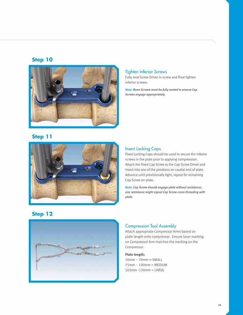
Tighten Inferior ScrewsFully seat Screw Driver in screw and final tighten
inferior screws.
Note: Bone Screws must be fully seated to ensure Cap
Screws engage appropriately.
Insert Locking Caps Fixed Locking Caps should be used to secure the inferior
screws in the plate prior to applying compression.
Attach the Fixed Cap Screw to the Cap Screw Driver and
insert into one of the positions on caudal end of plate.
Advance until provisionally tight, repeat for remaining
Cap Screw on plate.
Note: Cap Screw should engage plate without resistance;
any resistance might signal Cap Screw cross threading with
plate.
Step 10
Step 11
Compression Tool Assembly Attach appropriate Compressor Arms based on
plate length onto compressor. Ensure laser marking
on Compressor Arm matches the marking on the
Compressor.
Plate length: 30mm – 70mm = SMALL
75mm – 100mm = MEDIUM
105mm -130mm = LARGE
Step 12

21
Insert Compression PinInsert compression pin into non-fixed vertebral body
above the plate; ensuring the gap between the pin and
the plate is equal to the desired compression.
Compression Use the compressor to compress the cephalad
vertebral body relative to the plate using the
compression pin.
Step 13
Step 14

22
Option 1: The Bone Awl can be used to penetrate the
cortex of the vertebral body and create a pilot hole for
the screw. Place Awl into ATO Guide and advance into
bone.
Note: When using the Bone Awl caution should be taken to
ensure that the spinal canal is not violated. Fluoroscopy is
recommended during this step.
Step 15
Prepare Superior Bone Screw HolesWith compression maintained by the compression instrument proceed to preparing Bone Screw holes. There are two
options that can be used for preparing the screw hole.
Option 2: A 25mm and 60mm Drill is provided as an
alternative for preparing a screw hole. To use Drill,
attach Ratcheting Inline Handle, insert into ATO Guide
and advance clockwise until appropriate drill depth
is reached (confirm drill depth using flouro). Laser
marked lines on the Drills identify the depth of drill
engagement in bone.
An optional 5.5mm Tap is provided if needed. To use
Tap, attach Ratcheting Inline Handle, insert into ATO
Guide on opposite side from Fixation Pin and advance
clockwise until appropriate depth is reached (confirm
depth using flouro). Laser marked lines on the Tap
identify the depth of Tap engagement in bone. Rotate
counter-clockwise to remove.
Note: When using the Drill or Tap caution should be taken to
ensure that the spinal canal is not violated. Fluoroscopy is
recommended during each of these steps.
Note: The Drills have a positive stop at 25mm and 60mm.
The Tap has a positive stop at 61mm.

23
Bone Screw SelectionScrew length should be based off depth of drilling or
tapping. If it’s desired to use Depth Gauge to confirm
screw length, remove ATO guide to use Depth Gauge.
Depth Gauge may need to be pushed through the
cancellous bone to the desired depth. The lines on
the Depth Gauge will represent the appropriate screw
length.
Step 16
The V2F Anterior Fixation System offers 6.0mm and
7.0mm screw diameters choose appropriate length and
diameter screw.
Screw length
6mm Screw
7mm Screw

24
Bone Screw Insertion Connect the Screwdriver to either the Inline or
Ratcheting T-Handle.
Step 17
Attach screw onto Screw Driver and insert into prepared
screw hole. While ensuring Screw Driver is fully seated
in screw, advance until line on Screw Driver meets top
of ATO Guide. This position represents provisionally
tightened screws. Remove Screw Driver. Repeat steps
15-17 for adjacent screw hole.

25
Step 18
Final Tighten Bone Screws Fully seat Screw Driver in screw and final tighten,
repeat for remaining screw.
Step 19
Step 20
Remove ATO Guide With Compressor still in place remove Superior ATO
Guide.
Use ATO Holder to remove ATO Guide from plate. Insert
hex tip of ATO Holder into ATO Guide. Turn sleeve
clockwise to engage threaded post on ATO Guide.
Rotate top of ATO Holder counter clockwise to remove
ATO Guide from plate.

26
Insertion of Locking Caps Select the Fixed (Gold) Cap Screw and attach to the
Cap Screw Driver and insert into one of the positions
on plate. Advance until provisionally tight, repeat for
remaining Cap Screw.
Note: Cap Screw should engage plate without resistance;
any resistance might signal Cap Screw cross threading with
plate.
Remove Compressor and Compression Pin Use Compression Pin Inserter to remove Compression
Pin by turning it counter clockwise.
Step 21

27
Final Tightening Cap ScrewsAttach Cap Screw Driver to Torque Limiting
T-Handle. Fully seat Cap Screw Driver into one of
the provisionally tightened Cap Screws, and turn
clockwise until Torque Limiting T-Handle snaps.
Repeat step for remaining Cap Screws.
Note: 50 in lb. Torque Wrench must be used for final
tightening of Cap Screws
Step 22
Final Construct
Step 23

28
CorpectomyComplete corpectomy procedure. Remove any
osteophytes or boney protrusions that prevent the
plate from sitting flush on the vertebral body
Step 1
Free Hand Technique
The V2F Anterior Fixation Systems is designed to support a free hand insertion technique.
Plate SelectionUse calipers to determine plate length.
Step 2
29
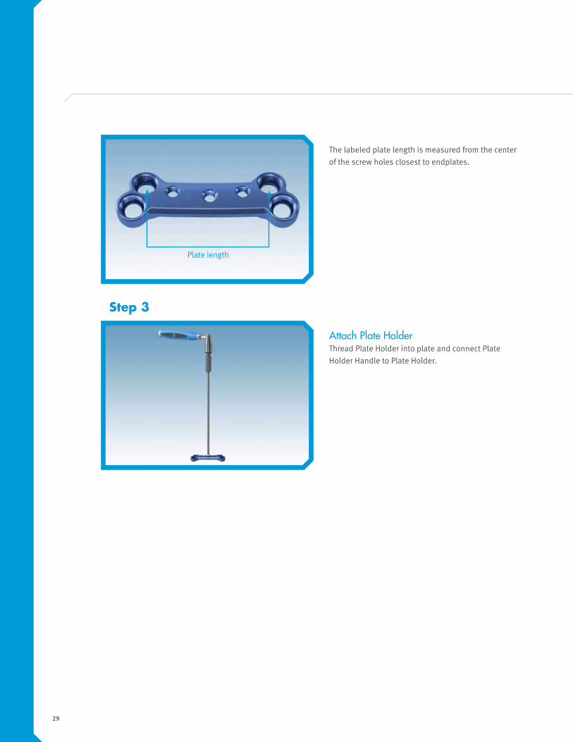
Attach Plate HolderThread Plate Holder into plate and connect Plate
Holder Handle to Plate Holder.
Step 3
The labeled plate length is measured from the center
of the screw holes closest to endplates.
Plate length

30
Temporary Fixation (Optional)Fixate the plate in position using Temporary Fixation
Pins. Insert Fixation Pin into Pin Inserter and place
through screw hole in opposite end of the plate that
you will be inserting your first screws. Turn clockwise
to advance the pin into the bone.
The Bone Awl can also be used as a temporary
fixation device. If this option is used follow Step 6,
option 1, and then repeat on opposite corner of plate
using second Awl or 25 or 60mm Drill. You can then
proceed directly to Step 8 for Bone Screw Insertion.
Step 5
Position PlatePosition plate on lateral aspect of spine confirming
the plate is in the desired position.
Note: Excessive force should not be applied to Plate Holder
Handle.
Step 4

31
Positive Stop
Depth Markings
Positive Stop
Depth MarkingsPositive Stop
Option 1: The Bone Awl can be used to penetrate the
cortex of the vertebral body and create a pilot hole for
the screw. Place Awl on opposite side from Fixation
Pin and advance into bone. The Awl has a positive
stop at 25mm.
Note: When using the Bone Awl, caution should be taken to
ensure that the spinal canal is not violated. Fluoroscopy is
recommended during this step.
Step 6
Prepare Bone Screw HolesThe Bone Screws can be inserted in a 30 degree cone relative to the plate. This 30 degree range cannot be exceeded in
order to guarantee Screws will seat completely within screw pocket of plate and allow for Cap Screw insertion.
Note: Care should be taken to ensure trajectory provides a safe screw placement relative to spinal canal and adjacent discs.
There are two options that can be used for preparing the screw hole.
Option 2: A 25mm and 60mm Drill is provided as an
alternative for preparing a screw hole. To use Drill,
attach Ratcheting Inline Handle, insert on opposite
side from Fixation Pin and advance clockwise until
appropriate drill depth is reached (confirm drill depth
using flouro). Laser marked lines on the Drills identify
the depth of drill engagement in bone.
An optional 5.5mm Tap is provided if needed. To use
Tap, attach Ratcheting Inline Handle, insert on opposite
side from Fixation Pin and advance clockwise until
appropriate depth is reached (confirm depth using
flouro). Laser marked lines on the Tap identify the
depth of Tap engagement in bone. Rotate counter-
clockwise to remove.
Note: When using the Drill or Tap caution should be taken to
ensure that the spinal canal is not violated. Fluoroscopy is
recommended during each of these steps.
Note: The Drills have a positive stop at 25mm and 60mm.
The positive stop for the Tap is 61mm.

32
Bone Screw SelectionInsert the Depth Gauge through the prepared screw
hole, the gauge may need to be pushed through the
cancellous bone to the desired depth. The lines on
the Depth Gauge will represent the appropriate screw
length.
Bone Screw Insertion Connect the Screw Driver to either the Inline or
Ratcheting T-Handle.
Step 7
Step 8
Screw length
6mm Screw
7mm Screw
The V2F Anterior Fixation System offers dual-lead
cortical/cancellous screws available in 6.0mm and
7.0mm diameters. Choose the appropriate length and
diameter screw. Screw lengths are measured from the
base of the screw head to the tip of the screw.

33
Attach screw onto Screw Driver and insert into
prepared screw hole ensuring Screw Driver is fully
seated in screw. Remove Screw Driver. Repeat steps
6-8 for adjacent screw hole.
Remove Temporary Fixation Pin Follow steps 6-8 for screw placement in the remaining
holes.
Step 9
Final Tighten Bone Screws Fully seat Screw Driver in screw and final tighten all
screws in a star pattern to ensure plate seats evenly
on vertebral bodies. Remove Plate Holder.
Note: Bone Screws must be fully seated to ensure Cap
Screws engage appropriately.
Step 10

34
Insertion of Locking Caps Select either the Fixed or Variable Cap Screw. The
Fixed Cap Screw will lock the screw in a fixed position
relative to the plate. The Variable Cap Screw will
allow the screw to accommodate subsidence of the
vertebral body. Attach the appropriate Cap Screw
to the Cap Screw Driver and insert into one of the
positions on plate. Advance until provisionally tight,
repeat for remaining Cap Screws
Note: Cap Screw should engage plate without resistance;
any resistance might signal Cap Screw cross threading with
plate.
Step 11
Final Tightening Cap Screws Attach Cap Screw Driver to Torque Limiting
T-Handle. Fully seat Cap Screw Driver into one of
the provisionally tightened Cap Screws, and turn
clockwise until Torque Limiting T-Handle snaps.
Repeat step for remaining Cap Screws.
Note: 50 in lb. Torque Wrench must be used for final
tightening of Cap Screws
Step 12
Final Construct
Step 13

35
Removal
The following outlines the suggested steps for removing the V2F Anterior Fixation System.
1. Attach Cap Screw Driver to either Ratcheting Inline or T-Handle.
2. Insert Cap Screw Driver into Cap Screw and rotate counter-clockwise to remove, repeat for all four Cap
Screws.
3. Attach Bone Screw Driver to either Ratcheting Inline or T-Handle.
4. Insert Bone Screw Driver into hex on top of Bone Screw and rotate counter-clockwise to remove, repeat for
all four Bone Screws.
5. Remove plate.

36
V2F Kit Contents
Part Number Description Standard Kit Quantity
07.01657.001 V2F, Plate, 30mm 1
07.01657.002 V2F, Plate, 35mm 1
07.01657.003 V2F, Plate, 40mm 1
07.01657.004 V2F, Plate, 45mm 1
07.01657.005 V2F, Plate, 50mm 1
07.01657.006 V2F, Plate, 55mm 1
07.01657.007 V2F, Plate, 60mm 1
07.01657.008 V2F, Plate, 65mm 1
07.01657.009 V2F, Plate, 70mm 1
07.01657.010 V2F, Plate, 75mm 1
07.01657.011 V2F, Plate, 80mm 1
07.01657.012 V2F, Plate, 85mm 1
07.01657.013 V2F, Plate, 90mm 1
07.01657.014 V2F, Plate, 95mm 1
07.01657.015 V2F, Plate, 100mm 1
07.01657.016 V2F, Plate, 105mm 1
07.01657.017 V2F, Plate, 110mm 1
07.01657.018 V2F, Plate, 115mm 1
07.01657.019 V2F, Plate, 120mm 1
07.01657.020 V2F, Plate, 125mm 1
07.01657.021 V2F, Plate, 130mm 1
07.01658.001 V2F, 6.0mm Screw, 30mm Length 6
07.01658.002 V2F, 6.0mm Screw, 35mm Length 6
07.01658.003 V2F, 6.0mm Screw, 40mm Length 6
07.01658.004 V2F, 6.0mm Screw, 45mm Length 6
07.01658.005 V2F, 6.0mm Screw, 50mm Length 6
07.01658.006 V2F, 6.0mm Screw, 55mm Length 6
07.01658.007 V2F, 6.0mm Screw, 60mm Length 6
07.01659.001 V2F, 7.0mm Screw, 30mm Length 6
07.01659.002 V2F, 7.0mm Screw, 35mm Length 6
07.01659.003 V2F, 7.0mm Screw, 40mm Length 6
07.01659.004 V2F, 7.0mm Screw, 45mm Length 6
07.01659.005 V2F, 7.0mm Screw, 50mm Length 6
07.01659.006 V2F, 7.0mm Screw, 55mm Length 6
07.01659.007 V2F, 7.0mm Screw, 60mm Length 6
07.01845.001 V2F, Plate Caddy Lid Large 1
Implant Tray

37
Part Number Description Standard Kit Quantity
07.01660.001 V2F, Fixed Cap Screw 8
07.01661.001 V2F, Variable Cap Screw 8
07.01838.001 V2F, Implant Tray 1
07.01839.001 V2F, 6.0mm Screw Caddy 1
07.01840.001 V2F, 6.0mm Screw Caddy Lid 1
07.01841.001 V2F, 7.0mm Screw Caddy 1
07.01842.001 V2F, 7.0mm Screw Caddy Lid 1
07.01843.001 V2F, Plate Caddy 1
07.01844.001 V2F, Plate Caddy Lid Small 1
07.01845.001 V2F, Plate Caddy Lid Large 1
07.01661.001 V2F, Variable Cap Screw
Implant Tray continued

38
Part Number Description Standard Kit Quantity
07.01662.001 ATO Guide, Superior 1
07.01663.001 ATO Guide, Inferior 1
07.01664.001 Plate Holder 1
07.01665.001 ATO Guide Handle 1
07.01735.001 ATO Holder 1
07.01666.001 V2F, Templating Calipers 1
07.01667.001 Ratcheting Driver Handle, Inline 2
07.01736.001 Ratcheting T-Handle 1
07.01669.001 V2F, Driver Handle, Torque-Limiting 1
07.01692.001 Cap Screw Driver 2
07.01670.001 Screw Driver 2
07.01671.001 Drill, 25mm Length 2
07.01671.002 Drill, 60mm Length 2
07.01673.001 Depth Gauge 1
07.01674.001 V2F, Tap for 6.0mm Screws 1
07.01676.001 V2F, Awl for 6.0mm Screws 2
07.01678.001 Fixation Pin Sterile Not in Tray
07.01679.001 Compression Pin Sterile Not in Tray
07.01680.001 Pin Inserter 1
07.01847.001 V2F, Instrument Tray 1
07.01848.001 V2F, Inner Instrument Tray 1
Instrument Tray

39
Part Number Description Standard Kit Quantity
07.01681.001 Compression Instrument 1
07.01682.001 Compression Tip Superior 1
07.01683.001 Short Compression Tip Inferior 1
07.01685.001 Medium Compression Tip Inferior 1
07.01687.001 Long Compression Tip Inferior 1
07.01668.001 Extended Ratcheting Driver Handle, Inline 1
07.01846.001 V2F, Compression Tray 1
Compression Set
40
Warnings, Precautions and Adverse Effects
Warnings
Some metals, polymers, chemicals, and other materials utilized with orthopedic implants have
been known to cause cancer and other adverse body reactions, or reports in the literature have
suggested such causation. Any factor that causes chronic damage to tissues may be oncogenic.
Cancer can metastasize from soft tissue sites (lung, breast, digestive system, and others) to bone,
including areas adjacent to implants, or it can be seeded to these locations during operative
and diagnostic procedures (such as biopsies). Paget’s disease has been reported to progress to
cancer; surgical candidates suffering from this disease should be warned accordingly.
Implantation of foreign material in tissues can elicit an inflammatory reaction. Current literature
suggests that wear debris (including metal, polyethylene, ceramic, and cement particles) can
initiate the process of histiocytic granuloma formation and consequent osteolysis and loosening.
Metal sensitivity has been reported following exposure to orthopedic implants. The most common
metallic sensitivities (nickel, cobalt, and chromium) are present in medical grade stainless steel
and cobalt-chrome alloys.
The V2F Lateral Plate System is a temporary internal fixation device. Internal fixation devices are
designed to stabilize the operative site during the normal healing process. After healing occurs,
these devices serve no functional purpose and it is recommended that the device is removed.
Implant removal, should be followed by adequate postoperative management to avoid fracture or
refracture.

41
Precautions
The selection of the proper size, shape and design of the implant for each patient is crucial to the
success of the procedure. Metallic surgical implants are subject to repeated stresses in use and
their strength is limited by the need to adapt the design to the size and shape of human bones.
Unless great care is taken in implant selection, proper placement of the implant and postoperative
management to minimize stresses on the implant, such stresses may cause metal fatigue and
consequent breakage, bending or loosening of the device before the healing process is complete.
This may in turn result in further injury or the need to remove the device prematurely.
The V2F Anterior Fixation System instrumentation should only be used after the surgeon has had
adequate training in this method of fixation and has become thoroughly knowledgeable about
the spinal anatomy and biomechanics. A surgical technique for the V2F System is available upon
request. This technique is not a substitute for training and is for general informational purposes only.
Components from other anterior thoracic and thoracolumbar plating systems must not be
intermixed with the V2F System components since compatibility of the components is not known.
Do not use implants made from dissimilar metals (such as cobalt chromium-molybdenum alloy or
stainless steel) in contact with components of the V2F System; otherwise, galvanic corrosion may
occur.
If contouring of the implant is necessary for optimal fit, the contouring should be gradual and
avoid any notching or scratching of the implant(s) surface. The plates must not be repeatedly or
excessively bent. Do not reverse bend the plate.
All implants and some instruments are intended for single use only; refer to the product label to
determine if the instrument is intended for single use only. Single use devices should not be re-
used. Possible risks associated with re-use of single use devices include:
• Mechanical malfunction
• Transmission of infectious agents

42
Adverse Effects
• Early or late loosening of the components
• Implant migration
• Disassembly, bending, loosening, slippage, and/or breakage of any or all of the components or
Instruments
• Foreign body reaction to the implants including possible tumor formation, autoimmune disease,
metallosis, and/or scarring
• Pressure on the skin possibly resulting in skin breakdown from component parts where there is
inadequate tissue coverage over the implant
• Implant or graft extrusion through the skin
• Wound complications
• Loss of proper spinal curvature, correction, height and/or reduction
• Infection
• Bone fracture or stress shielding at, above, or below the level of surgery
• Non-union (or pseudoarthrosis)
• Loss of neurological function, appearance of radiculopathy, dural tears, and/or development of pain
• Neurovascular compromise including paralysis or other types of serious injury
• Cerebral spine fluid leakage
• Gastrointestinal, urological, and/or reproductive system compromise including sterility,
impotency, and/or loss of consortium
• Hemorrhage of blood vessels and/or hematomas
• Cessation of growth of the fused portion of the spine
• Discitis, arachnoiditis, and/or other types of inflammation
• Deep venous thrombosis, thrombophlebitis, and/or pulmonary embolus
• Bone graft donor site pain
• Inability to resume activities of normal daily living
• Death
NOTE: Additional surgery may be necessary to correct some of these anticipated adverse reactions.
43
Unless otherwise specified in extended warranty plans or other Zimmer written materials
pertaining to a particular product, Zimmer warrants to customer that products purchased from
Zimmer conform to Zimmer's published specifications and are free from defects in workmanship
and material at the time of shipment. If, upon inspection within a reasonable time after
delivery and before implantation or use, customer discovers a failure of a product to conform to
specifications or a defect in material and workmanship, it must promptly notify Zimmer in writing.
Within a reasonable time after such notification, Zimmer will correct any failure of the product to
conform to the warranty by providing, at its option, repair of the product, a replacement unit, or a
refund of the purchase price, if applicable. The aforementioned remedies are customer's exclusive
remedies for breach of warranty.
The warranties provided, unless otherwise agreed to in writing expressly provided in the product
specifications, shall extend for a period of one (1) year commencing on the date of shipment of
the product to customer.
This warranty does not extend or cover (a) any product, components, or parts not manufactured
or sold by Zimmer, (b) damage caused by use of any product for purposes other than those for
which it was designed, (c) damage caused by unauthorized attachments or modification, (d)
damage caused during shipment, (e) any other abuse or misuse by customer, its employees,
representatives, contractors and agents, or (f) any Zimmer product where the customer is not the
first purchaser of the product.
THE FOREGOING WARRANTIES ARE IN LIEU OF ALL OTHER WARRANTIES, EXPRESS OR IMPLIED,
RELATING TO THE PRODUCTS OR MATERIALS TO BE PROVIDED, INCLUDING BUT NOT LIMITED TO THE
IMPLIED WARRANTIES OF MERCHANTABILITY OR FITNESS FOR A PARTICULAR PURPOSE. ALL SUCH
OTHER WARRANTIES AND REPRESENTATIONS ARE HEREBY DISCLAIMED.
Warranty

44

Solutions by the people of Zimmer Spine.
You are devoted to helping your patients reduce their pain and improve their lives.
And the people of Zimmer Spine are devoted to you. We are dedicated to supporting
you with best-in-class tools, instruments and implants. We are driven by the opportunity
to share our unrivaled education and training. We are committed partners who will
do everything in our power to assist you in your quest to provide the absolute best in
spinal care. And we can be counted on always to act with integrity as ethical partners
who are worthy of your trust. We are the people of Zimmer Spine.
Manufactured by:
Zimmer Spine7375 Bush Lake RoadMinneapolis, MN 55439800.655.2614
Technology Center:
Zimmer Spine 5301 Riata Park Court, Building FAustin, Texas 78727512.918.2700
zimmerspine.com
L1618 Rev A per DCR 10448© 2013 Zimmer Spine, Inc.
This documentation is intended exclusively for physicians and is not intended for laypersons. Information on the products and procedures contained in this document is of a general nature and does not represent and does not constitute medical advice or recommendations. Because this information does not purport to constitute any diagnostic or therapeutic statement with regard to any individual medical case, each patient must be examined and advised individually, and this document does not replace the need for such examination and/or advice in whole or part. Please refer to the package inserts for important product information, including, but not limited to, contraindications, warnings, precautions, and adverse effects.
Federal (USA) law restricts this device to sale by or on the order of a physician.