v1280_sc_command_reference.doc
TRANSCRIPT

V1280 SC command reference (Firmware 5.20.*)
1. Alphabetical Command Reference 1System Controller Command Summary 1FRU State and Test Status 3Alphabetical Listing of System Controller Commands 5addcodlicense 6bootmode 7break 9console 10deletecodlicense 11disablecomponent 13enablecomponent 14flashupdate 15help 18history 20inventory 21logout 22password 23poweroff 24ivpoweron 26reset 28resetsc 30restartssh 32setalarm 33setdate 34setescape 37seteventreporting 39setlocator 41setls 42setupnetwork 46setupsc 48showalarm 52showboards 54showcodlicense 65showcodusage 67showcomponent 69showdate 72showenvironment 73showerrorbuffer 78showescape 81showeventreporting 82showfault 83showhostname 84showlocator 85showlogs 86showmodel 91shownetwork 92Contents vshowresetstate 94showsc 95shutdown 96ssh-keygen 97testboard 99Glossary 101

Index 103Command Descriptionaddcodlicense Adds a Capacity on Demand (COD) right-to-use (RTU) license keyto the COD license database.bootmode Configures the way the Solaris OS boots at the next reboot.break Sends a break signal to the console.console Opens a console connection.deletecodlicense Removes a Capacity on Demand (COD) right-to-use (RTU) licensekey from the COD license database.disablecomponent Deprecated starting with the 5.17.0 release. Replaced by the setlscommand.enablecomponent Deprecated starting with the 5.17.0 release. Replaced by the setlscommand.flashupdate Updates the flash PROMs.2help Provides basic help information.history Shows the command history along with date and time stamps.inventory Shows the SEPROM contents of a FRU or system.logout Logs out from this connection.password Sets the LOM access password.poweroff Powers off system or components.poweron Powers on system or components.reset Resets the system.resetsc Resets the system controller (LOM).restartssh Restarts the SSH server, loading and storing latest host keys.setalarm Sets system alarms.setdate Sets the time, date, and time zone for the system controller.setescape Sets LOM escape characters.seteventreporting Sets event reporting.setlocator Sets locator light.setls Sets the component location status. Replaces enablecomponentand disablecomponent commands starting with the 5.17.0release.setupnetwork Sets up LOM network settings.setupsc Configures the system controller (LOM)showalarm Displays state of system alarms LEDs.showboards Lists status and assignment information for boards in the system.showcodlicense Displays the current Capacity on Demand (COD) right-to-use (RTU)licenses stored in the COD license database.showcodusage Displays the current usage statistics for Capacity on Demand (COD)resources.showcomponent Displays a component or a list of components.showdate Displays the time and date.showenvironment Displays the current environmental status, temperatures, currents,voltages, fan speeds, and so on.showerrorbuffer Shows the contents of the error buffer.showescape Displays LOM escape characters.TABLE 1 System Controller Command Summary (Continued)Command DescriptionAlphabetical Command Reference 3FRU State and Test StatusTABLE 2 and TABLE 3 describe the FRU states and the current test status.showeventreporting Displays event reporting status.showfault Displays state of system fault LED.showhostname Displays the host name.showlocator Displays state of system locator LED.

showlogs Shows the logs.showmodel Displays the platform model.shownetwork Displays LOM network settings.showresetstate Displays the CPU registers after a reset.showsc Displays the system controller uptime and version information.shutdown Shuts down Solaris and takes the system to standby mode.ssh-keygen Generates SSH host keys and displays host key fingerprint on thesystem controller.testboard Tests the CPU/Memory board in isolation.TABLE 2 FRU StatesValue DefinitionDisabled FRU has been blacklisted (RPx only).Assigned FRU is assigned to the system.Active FRU is in use by the systemAuto Speed Fans run at thermally regulated speed (FT0 only).High Speed Fans run at maximum speed (FT0 only).Unknown Speed Fans run at unknown speed (FT0 only).Main FRU is the Main System Controller (SSC1 only).Unknown FRU State is unknown.– FRU State is not relevant.TABLE 1 System Controller Command Summary (Continued)Command Description4TABLE 3 Test StatusTest Status DescriptionPassed/OK All board components passed all tests.Degraded A test failed, a failure occurred during normal operation, or acomponent has been disabled. The board is still accessible and someof its devices can still be used.Disabled The FRU has been blacklisted.Failed The board failed a test.Under Test The system is running POST (power-on self-test). The board status istransitioning between Assigned and Active.Not Tested No testing has been done.– The slot is empty or not tested. Not applicable for this device.Alphabetical Command Reference 5Alphabetical Listing of SystemController CommandsThe following sections describe the System Controller commands.6addcodlicenseAdds a Capacity on Demand (COD) right-to-use (RTU) license key to the CODlicense database.Syntaxaddcodlicense license-signatureaddcodlicense -hOptions/ParametersThe following table lists all options or parameters and describes their use:DescriptionAdds the specified COD RTU license key to the COD license database on the systemcontroller.Note – Before you run this command, you must obtain a COD RTU license key fromthe Sun License Center. For details on COD RTU license keys, refer to the Sun FireEntry-Level Midrange System Administration Guide.See Alsodeletecodlicense, showcodlicense, showcodusage

license-signature The COD RTU license key to be added to the COD licensedatabase.-h Displays help for this command.Alphabetical Command Reference 7bootmodeConfigures the way Solaris software uses the OpenBoot™ PROM to boot at the nextreboot.Syntaxbootmode normalbootmode [diag|skipdiag] [forth] [reset_nvram]bootmode –hOptions/ParametersThe following table lists all options or parameters and describes their use:DescriptionConfigures the way Solaris software boots at the next reboot.When a bootmode command is issued it sets a flag that is read by the OpenBootPROM at the next Solaris reboot. If the system is not rebooted with 10 minutes thebootmode value is restored to normal. Once the system has been rebooted the–h Displays help for this commandnormal Instructs the OpenBoot™™™™ PROM on the next reboot toboot the system using the values held in the OpenBootPROM variables verbosity-level and diag-level. Thisvalue also clears any previously requested bootmodecommand that had not timed out.diag Instructs the OpenBoot PROM on the next reboot to bootthe system as if the CPU POST verbosity-level had beenset to max and the diag-level to max. This ensuresthat the highest level of POST tests are run prior toSolaris booting.skipdiag Instructs the OpenBoot PROM on the next reboot to bootthe system as if the CPU POST verbosity-level had beenset to min and the diag-level to init. This causes thefastest POST pass prior to booting Solaris.forth Instructs the OpenBoot PROM on the next reboot to stopat the ok prompt even if the OpenBoot PROM variableauto-boot? is set to true. This prevents automaticbooting to Solaris for that boot attempt.reset_nvram Instructs the OpenBoot PROM to reset its OpenBoot PROMNVRAM variables on the next reboot.8bootmode value is also set to normal. When bootmode is set to normal theOpenBoot PROM values verbosity-level and diag-level are used directly byOpenBoot PROM to control the POST behavior at boot time.See Alsoreset, break, OBP setenv (verbosity-level, diag-level)Example■ To instruct the OpenBoot PROM to use the skipdiag option:lom> bootmode skipdiagAlphabetical Command Reference 9breakSends a break signal to the Solaris console.Syntaxbreak [–y|–n]break –hOptions/ParametersThe following table lists all options or parameters and describes their use:

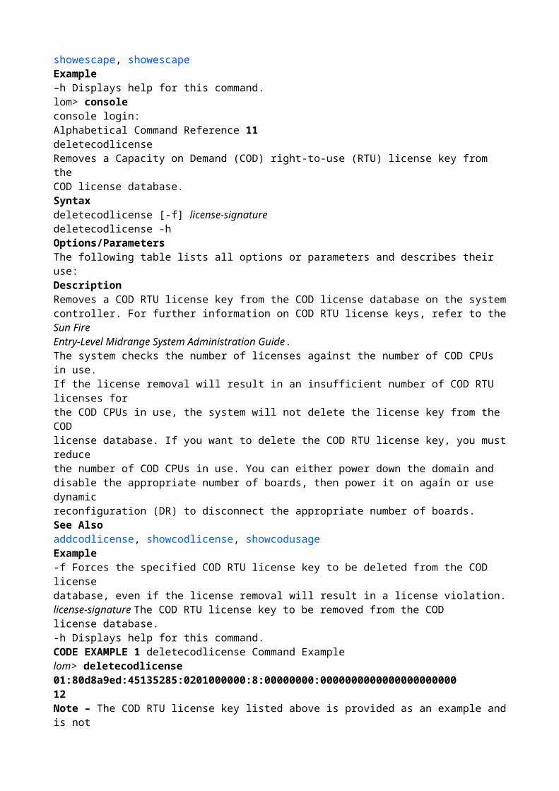
DescriptionSends a 30 ms break signal to the Solaris console.The Solaris console is resumed after sending the break signal. When the SolarisOperating System is running, and providing the system is not in secure mode, thenthe usual effect of this command is to force entry into the PROM or the debugger.See Alsoconsole, setupscExample–y Does not prompt for confirmation.–n Does not execute the command if confirmation isrequested.–h Displays help for this command.■ To use the break command to drop the system from running Solaris to theOpenBoot PROM:lom> breakThis will suspend Solaris.Do you want to continue? [no] yType ’go’ to resume{0} ok10consoleConnect to the Solaris or OpenBoot PROM console.Syntaxconsoleconsole –hOptions/ParametersThe following table lists all options or parameters and describes their use:DescriptionIf the Solaris OS or OpenBoot PROM is booted, leave the lom> prompt and connectto the Solaris or OpenBoot PROM console. The system remains in console modeuntil the LOM escape sequence is typed.Note – After issuing the console command and pressing Return, note that noprompt is displayed until you press Return again. If there is output being sent to theSolaris console at the time then the command will continue immediately.See Alsoshowescape, showescapeExample–h Displays help for this command.lom> consoleconsole login:Alphabetical Command Reference 11deletecodlicenseRemoves a Capacity on Demand (COD) right-to-use (RTU) license key from theCOD license database.Syntaxdeletecodlicense [-f] license-signaturedeletecodlicense -hOptions/ParametersThe following table lists all options or parameters and describes their use:DescriptionRemoves a COD RTU license key from the COD license database on the systemcontroller. For further information on COD RTU license keys, refer to the Sun FireEntry-Level Midrange System Administration Guide.The system checks the number of licenses against the number of COD CPUs in use.If the license removal will result in an insufficient number of COD RTU licenses forthe COD CPUs in use, the system will not delete the license key from the COD

license database. If you want to delete the COD RTU license key, you must reducethe number of COD CPUs in use. You can either power down the domain anddisable the appropriate number of boards, then power it on again or use dynamicreconfiguration (DR) to disconnect the appropriate number of boards.See Alsoaddcodlicense, showcodlicense, showcodusageExample-f Forces the specified COD RTU license key to be deleted from the COD licensedatabase, even if the license removal will result in a license violation.license-signature The COD RTU license key to be removed from the CODlicense database.-h Displays help for this command.CODE EXAMPLE 1 deletecodlicense Command Examplelom> deletecodlicense 01:80d8a9ed:45135285:0201000000:8:00000000:000000000000000000000012Note – The COD RTU license key listed above is provided as an example and is nota valid license key.Alphabetical Command Reference 13disablecomponentThe disablecomponent command has been deprecated starting with the 5.17.0release and has been replaced by the setls command. It is suggested that you usethe setls command even though the disablecomponent command is stillavailable. For further information, see the setls command description.See Alsosetls14enablecomponentThe enablecomponent command has been deprecated starting with the 5.17.0release and has been replaced by the setls command. It is suggested that you usethe setls command even though the enablecomponent command is stillavailable. For further information, see the setls command description.See AlsosetlsAlphabetical Command Reference 15flashupdateUpdates the flash PROMs in the system controller, all the system boards, or aspecified board number.Syntaxflashupdate [–y|–n] –f URL allflashupdate [–y|–n] –f URL systemboards|rtos|scapp|board ...flashupdate [–y|–n] –uflashupdate [–y|–n] –c source-board destination-boardflashupdate –hOptions/ParametersThe following table lists all options or parameters and describes their use:When you flash update the system controller, the command gives you the followingmessage:–y Does not prompt for confirmation.–n Does not execute the command if confirmation isrequested.–f Specifies a URL as the source of the flash images:URL is the URL of the directory containing the flash images.Supported protocols are:ftp://[userid:password@]hostname/pathhttp://hostname/path
–c Specifies a board as the source of the flash images.–u Upgrades boards to the current firmware level.all The system controller and all system boards.rtos The Real Time Operating System for the systemcontroller. This requires the system controller to berebooted.scapp The system controller. This requires the SystemController to be rebooted.systemboards All CPU/Memory boards and I/O assemblies, that is, SB0,SB2, SB4 and IB6.–h Displays help for this command.16Note – flashupdate cannot retrieve flash images from a secure (passwordprotected)HTTP URL. A message of the form flashupdate: failed, URL doesnot contain required file: file is returned, although the file may exist.DescriptionUpdates the flash PROMs in the system controller, all the system boards, or aspecified board number.The flash PROMs are located on the CPU/Memory boards, I/O assembly, andsystem controller boards. There are no flash PROMs on the Repeater boards.See AlsoSun Fire Entry-Level Midrange System Administration Guide for step-by-stepprocedures on how to update the firmware.Examples■ To update the specified flash PROM in the I/O assembly:■ To update CPU/Memory board sb0As part of this update, the system controller will automatically reboot.ScApp will be upgraded automatically during the next boot.Rebooting will interrupt any current operations.This includes keyswitch changes, Solaris rebootsand all current connections.Do you want to continue? [no]CODE EXAMPLE 2 Using flashupdate to Update a Flash PROM in the I/O Assemblylom> flashupdate -f ftp://host/path ib6Waiting for critical processes to finish. This may take a while.Critical processes have finished.Retrieving: ftp://host/path/lw8pci.flashValidating ...... DoneProgramming PROM /N0/IB6/FP0Erasing ..... DoneProgramming ..... DoneVerifying ..... DoneAlphabetical Command Reference 17■ To update the system controller firmware:lom> flashupdate ftp://host/path sb0Waiting for critical processes to finish. This may take a while.Critical processes have finished.Retrieving: ftp://host/path/lw8cpu.flashValidating .............. DoneProgramming PROM /N0/SB0/FP0Erasing ............. DoneProgramming ............. DoneVerifying ............. DoneProgramming PROM /N0/SB0/FP1Erasing ............. DoneProgramming ............. Done

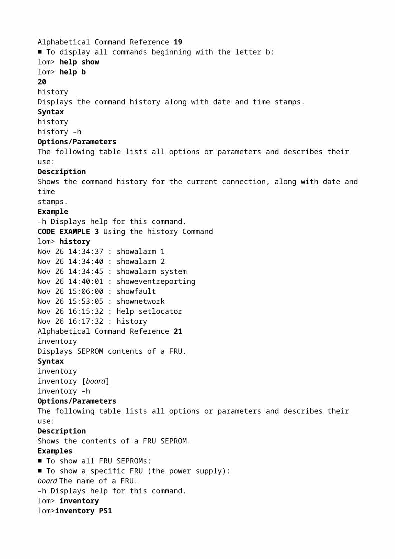
Verifying ............. Donelom>lom>flashupdate -f ftp://host/path scappAs part of this update, the system controller will automatically reboot.ScApp will be upgraded automatically during the next boot.Rebooting will interrupt any current operations.This includes keyswitch changes, Solaris rebootsand all current connections.Do you want to continue? [no]18helpWithout arguments, list all available LOM commands. When an argument issupplied, display basic usage of the specified command and a short description.Syntaxhelp [command-name]help [partial-command-name]help –hOptions/ParametersThe following table lists all options or parameters and describes their use:DescriptionThe help command, without arguments, lists all available LOM commands. Whenan argument is supplied, the help command displays basic usage of the specifiedcommand and a short description.Examples■ To display help information on the setlocator command:■ To display all commands beginning with show:command-name The name of the LOM command.partial-command-name One or more letters of the command name, such asshow.–h Displays help for this command.lom> help setlocatorsetlocator -- set the system locator ledUsage: setlocator on|offsetlocator –h–h -- display this help messagelom>Alphabetical Command Reference 19■ To display all commands beginning with the letter b:lom> help showlom> help b20historyDisplays the command history along with date and time stamps.Syntaxhistoryhistory –hOptions/ParametersThe following table lists all options or parameters and describes their use:DescriptionShows the command history for the current connection, along with date and timestamps.Example–h Displays help for this command.CODE EXAMPLE 3 Using the history Commandlom> historyNov 26 14:34:37 : showalarm 1

Nov 26 14:34:40 : showalarm 2Nov 26 14:34:45 : showalarm systemNov 26 14:40:01 : showeventreportingNov 26 15:06:00 : showfaultNov 26 15:53:05 : shownetworkNov 26 16:15:32 : help setlocatorNov 26 16:17:32 : historyAlphabetical Command Reference 21inventoryDisplays SEPROM contents of a FRU.Syntaxinventoryinventory [board]inventory –hOptions/ParametersThe following table lists all options or parameters and describes their use:DescriptionShows the contents of a FRU SEPROM.Examples■ To show all FRU SEPROMs:■ To show a specific FRU (the power supply):board The name of a FRU.–h Displays help for this command.lom> inventorylom>inventory PS1/N0/PS1: PS: 300-1523-01-02 serial# E00254 "Power Supply (A166,V1280)"Made on Fri Nov 30 11:47:41 PST 2001 by 03ad at DELTAELECTRONICS CHUNGLITAIWANPowered on for 87 days 12 hours 1 minute22logoutLogs out from this connection.Syntaxlogoutlogout –hOptions/ParametersThe following table lists all options or parameters and describes their use:DescriptionOnly one user can be logically connected to the system console or LOM prompt atany one time. If you wish to establish a connection through the system controllernetwork port then you must first make the connection available by logging out ofthe serial port connection. The same is true if you are logged into the network portbut wish to connect over the serial port.Note – Typing another character on the serial port after logging out from the serialport is interpreted as an attempt to reconnect the connection.Example–h Displays help for this command.lom> logoutAlphabetical Command Reference 23passwordSets the password for the LOM.Syntaxpasswordpassword –hOptions/ParametersThe following table lists all options or parameters and describes their use:

DescriptionSets the password for establishing connections to the shared LOM/console port, andfor other password-protected activities. Prior to allowing the password to bechanged, the current password will be authenticated. Changed passwords take effectimmediately. The old password will no longer be accepted.You can remove the password by pressing Return at the Enter new password andEnter new password again prompts.If your password has been lost or forgotten, contact SunService for advice.See Also■ setupsc■ reset■ break■ Sun Fire Entry-Level Midrange System Administration Guide.ExampleYou see the following display when you type the password command at the LOMshell.–h Displays help for this command.CODE EXAMPLE 4 Using the password Commandlom> passwordEnter current password:Enter new password:Enter new password again:lom>24poweroffForcibly powers off the whole system to standby, or a FRU, or a list of FRUs.Syntaxpoweroffpoweroff [–y|–n]poweroff [–y|–n] fru-name [fru-name...]poweroff –hOptions/ParametersThe following table lists all options or parameters and describes their use:Descriptionpoweroff fru-name powers off a FRU or set of FRUs, which can be:■ Power supply (psx)■ System board (sbx, ibx, rpx)■ Fan tray (ft0)poweroff without an argument explicitly terminates the Solaris system beforeproceeding to power off the FRUs. The power status of each board is displayed bythe showboards output.Note – In normal circumstances use the shutdown command.See Alsopoweron, shutdown–y Answers yes to all questions. This option is potentiallyhazardous. You can forcefully power off a component withthe –y option.–n Answers no to all questions. You cannot forcefully poweroff a component with the –n option.fru-name The name of an individual FRU.–h Displays help for this command.Alphabetical Command Reference 25Examples■ To power off CPU/Memory board sb2, type:■ To terminate and power off the entire system, type:lom> poweroff sb2
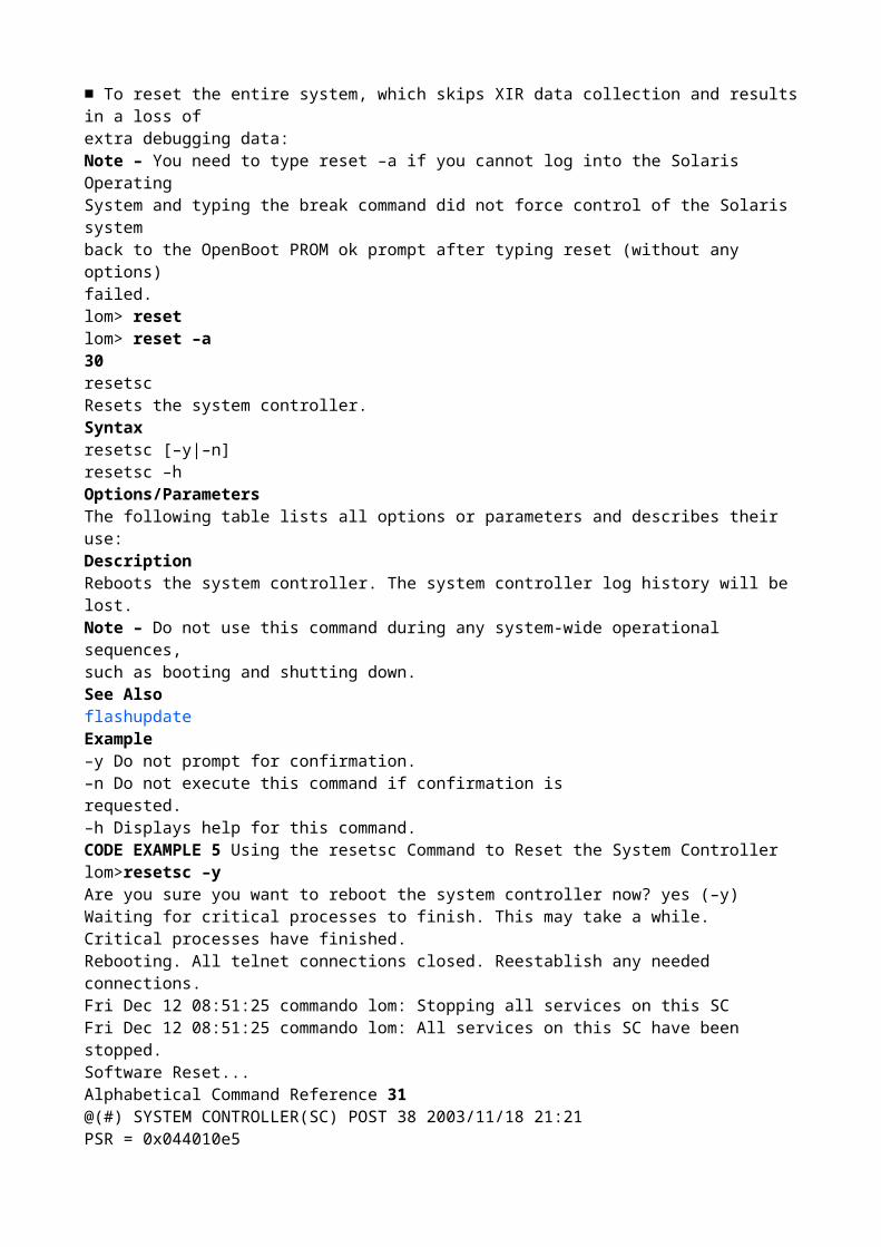
lom> poweroff26poweronPowers on the entire system, or a FRU, or a list of FRUs.Syntaxpoweronpoweron [all|fru-name [fru-name...]]poweron –hOptions/ParametersThe following table lists all options or parameters and describes their use:Descriptionpoweron without an argument is the normal way to power on a system fromstandby and boot Solaris.poweron fru-name powers on a FRU or set of FRUs, which can be:■ Power supply (psx)■ System board (sbx, ibx, rpx)■ Fan tray (ft0)Note – poweron all powers on all FRUs without booting the Solaris OS. Thepower status of each board is displayed by the showboards output.See Alsoshutdown, showboards, poweroffExamples■ To power on and boot the entire system, type:–y Does not prompt for confirmation.–n Does not execute the command if confirmation isrequested.fru-name Powers on a FRU or set of FRUs.all Powers on all FRUs but does not boot Solaris.–h Displays help for this command.Alphabetical Command Reference 27■ To power on CPU/Memory board sb2, type:lom> poweronlom>poweron sb228resetResets the Solaris system.Syntaxreset [–x|–a] [–y|–n]reset –hOptions/ParametersThe following table lists all options or parameters and describes their use:Note – Typing reset, without options, is the same as reset –x.DescriptionResets the Solaris system. The operation is not allowed if the system is in securemode or powered down to standby mode. The Solaris system console will beresumed after completing the reset.By default, reset uses XIR (eXternally Initiated Reset) to reset the CPU processorsin the Solaris system. The XIR forces control of the Solaris system into the OpenBootPROM and begins the OpenBoot PROM’s error reset recovery actions. The errorreset recovery actions preserve most Solaris system states to allow the collection ofthe data needed for debugging the hardware and software, including a SolarisOperating System core file. The OpenBoot PROM’s error reset recovery actions arecontrolled by setting the OpenBoot PROM error-reset-recovery configurationvariable.–y Does not prompt for confirmation.–n Does not execute the command if confirmation is

requested.–x Forces the default behavior of reset via XIR(Externally initiated reset).–a Resets all hardware. Skips externally initiated reset(XIR) data collection. Loss of extra debugging dataresults.–h Displays help for this command.Alphabetical Command Reference 29If you cannot log into the Solaris Operating System and typing the break commanddid not force control of the Solaris system back to the OpenBoot PROM ok prompt),after you type the reset command for the first time, you must next type reset –ain order to reset everything.The reset –a command is equivalent to the OpenBoot PROM reset-all word.See Also■ setupsc■ Sun Fire Entry-Level Midrange System Administration Guide for step-by-stepprocedures on recovering from a hung or hard hung Solaris system.Examples■ To reset the Solaris system:■ To reset the entire system, which skips XIR data collection and results in a loss ofextra debugging data:Note – You need to type reset –a if you cannot log into the Solaris OperatingSystem and typing the break command did not force control of the Solaris systemback to the OpenBoot PROM ok prompt after typing reset (without any options)failed.lom> resetlom> reset –a30resetscResets the system controller.Syntaxresetsc [–y|–n]resetsc –hOptions/ParametersThe following table lists all options or parameters and describes their use:DescriptionReboots the system controller. The system controller log history will be lost.Note – Do not use this command during any system-wide operational sequences,such as booting and shutting down.See AlsoflashupdateExample–y Do not prompt for confirmation.–n Do not execute this command if confirmation isrequested.–h Displays help for this command.CODE EXAMPLE 5 Using the resetsc Command to Reset the System Controllerlom>resetsc –yAre you sure you want to reboot the system controller now? yes (–y)Waiting for critical processes to finish. This may take a while.Critical processes have finished.Rebooting. All telnet connections closed. Reestablish any needed connections.Fri Dec 12 08:51:25 commando lom: Stopping all services on this SCFri Dec 12 08:51:25 commando lom: All services on this SC have been stopped.Software Reset...Alphabetical Command Reference 31

@(#) SYSTEM CONTROLLER(SC) POST 38 2003/11/18 21:21PSR = 0x044010e5PCR = 0x04004000Memory size = 128MBBasic sanity checks done.Skipping POST ...ERI Device PresentGetting MAC address for SSC1Using SCC MAC addressMAC address is 0:3:ba:19:8b:92Hostname: commandoAddress: 129.xxx.xxx.xxxNetmask: 255.255.255.0Attached TCP/IP interface to eri unit 0Attaching interface lo0...doneGateway: 129.xxx.xxx.xxxinterrupt: 100 Mbps full duplex link upCopyright 2001-2004 Sun Microsystems, Inc. All rights reserved.Use is subject to license terms.Sun Fire System FirmwareRTOS version: 38ScApp version: 5.17.0 Build_02SC POST diag level: offThe date is Friday, December 12, 2003, 8:52:42 AM PST.Fri Dec 12 08:52:43 commando lom: Boot: ScApp 5.17.0, RTOS 38Fri Dec 12 08:52:45 commando lom: SBBC Reset Reason(s): Peer Reset, WatchdogResetFri Dec 12 08:52:51 commando lom: Caching ID informationFri Dec 12 08:52:52 commando lom: Clock Source: 75MHzFri Dec 12 08:52:57 commando lom: /N0/PS0: Status is OKFri Dec 12 08:52:58 commando lom: /N0/PS1: Status is OKFri Dec 12 08:52:58 commando lom: /N0/PS2: Status is OKFri Dec 12 08:52:59 commando lom: /N0/PS3: Status is OKFri Dec 12 08:52:59 commando lom: Chassis is in single partition mode.Connected.CODE EXAMPLE 5 Using the resetsc Command to Reset the System Controller (Continued)32restartsshRestarts the SSH server.Syntaxrestartssh [-h]Options/ParametersThe following table lists all options or parameters and describes their use:DescriptionTo run this command, SSH must be enabled using the setupnetwork command.If you have generated new host keys using ssh-keygen, you must restart the SSHserver before the new host keys can take effect. By restarting the server, the keys areloaded into memory and stored in the SSH server’s dedicated memory structure.When restarting the SSH server, all existing SSH connections are closed. Thecommand posts an informational message, asking for confirmation before actuallyrestarting the SSH server. You can skip confirmation by specifying the –y or –nswitch.If you have issued the command over an SSH connection, the connection terminateswhen the SSH server restarts. Since the process only takes seconds, you can reestablish

the SSH connection immediately.See Alsossh-keygen-y Answers yes to the informational message. Does notprompt for confirmation.-n Answers no to the informational message. Does notexecute the command if confirmation is required.-h Displays help for this command.Alphabetical Command Reference 33setalarmSets the system alarm relays and associated LEDS.Syntaxsetalarm 1|2|3 on|offsetalarm –hOptions/ParametersThe following table lists all options or parameters and describes their use:DescriptionSets the system alarm relays and associated LEDs. For information about the systemalarm, UNIX running LED, and Alarm 3, see Appendix A of the Sun Fire Entry-LevelMidrange System Administration Guide.See AlsoshowalarmExamples1 Specifies alarm number 12 Specifies alarm number 23 Specifies alarm number 3on Turns on the specified alarm relay and LED.off Turns off the specified alarm relay and LED.–h Displays help for this commandlom> setalarm 1 onlom> setalarm 2 off34setdateSet the date and time for the system.Syntaxsetdate [–v] [–t time-zone] [mmdd]HHMMsetdate [–v] [–t time-zone] mmddHHMM[[cc]yy]][.SS]setdate [–v] –r datehostsetdate [–v] –t GMT <+|–> offset-from-GMTsetdate –hOptions/ParametersThe following table lists all options or parameters and describes their use:Note – For a full listing of time zones, type showdate –t –v.DescriptionSets the date and time.–v Verbose mode.–t time-zone Sets the time zone using the time zoneabbreviation.–t GMT<+|–>offset-from-GMT Sets the time to GMT plus the specifiedoffset.mm Month numberdd Day number in the monthHH Hour number (24–hour system)MM Minute numbercc First two digits of year numberyy Last two digits of the year number

SS Second number.–r datehost Sets the date based on the current valuesof datehost. The host must be a valid system.–h Displays help for this command.Alphabetical Command Reference 35Note – If your time zone area is using daylight savings or summer time, the dateand time is set automatically.Note – If Solaris is running you must use the Solaris date(1) command.See AlsoshowdateExamples■ To set the date and time to Thursday, April 20, 2000 at 18 hours 15 minutes and 10seconds:■ To set the date from the datehost system:■ To set the date and time to Thursday, April 20, 2000 at 18 hours 15 minutes and 10seconds and the time zone to Eastern Standard Time (EST), using the time zoneabbreviations, type:■ To set just the time zone for the UK, type:lom> setdate 042018152000.10lom> setdate –r hostnameMon Apr 03 09:30:58 PST 2000lom> setdate –t EST 042018152000.10lom> setdate –t Europe/London36To set the time zone for European Central Time using the time zone abbreviationsand not the date and time, type:lom> setdate –t ECTAlphabetical Command Reference 37setescapeSets the sequence of characters used to switch from the Solaris or OpenBoot PROMconsole to the LOM prompt.Syntaxsetescape escapecharssetescape –hOptions/ParametersThe following table lists all options or parameters and describes their use:DescriptionSets the sequence of characters used to switch from the Solaris or OpenBoot PROMconsole to the LOM prompt.If you are typing at the console and type the first character of the escape sequence(by default this is #), there is a one second delay before the character appears on thescreen. This is because the system waits for one second to see if the next character inthe escape sequence is about to be typed. If the next character is typed then thesystem waits up to one second for the next character and so on. If you type all thecharacters in the escape sequence then the lom> prompt appears. If you do not, thenthe characters belonging to the escape sequence that were typed are output to thescreen.Choose an escape sequence that does not start with a sequence of characters that isfrequently typed at the console, otherwise the delay between your striking the keysand the character appearing on the screen may be confusing and affect your typing.See AlsoshowescapeExamples■ To set the escape characters to #. type:escapechars Up to five alphanumeric characters can be specified asthe escape sequence. The default sequence when the LOM
is first started is a pound (#) followed by a period(.), that is, #.–h Displays help for this command.38Note – As # is the comment character for the LOM command shell the sequencemust be enclosed in quotes.■ To set the escape characters to ~~~.. type:lom> setescape "#."lom> setescape ~~~..Alphabetical Command Reference 39seteventreportingThe seteventreporting command controls which messages are printed at theLOM prompt and the level of logged messages sent to Solaris.Syntaxseteventreporting on [0|1|2|3|4]seteventreporting off [0|1|2|3|4]seteventreporting default [0|1|2|3|4]seteventreporting –hOptions/ParametersThe following table lists all options or parameters and describes their use:The reporting levels are:Note – If not specified, the default reporting level is 3.default By default the LOM software prints messages at the lom>prompt, but only when Solaris is not running. TheSolaris software prints messages from the LOM asdirected by the syslogd system log daemon configurationfile /etc/syslog.conf.on All messages are reported to the lom> prompt at thecurrently set reporting level and below.off No messages are reported to the lom> prompt. Messagescontinue to be sent to Solaris at the current reportinglevel and below.0 No messages are reported.1 Only fatal messages are reported.2 Fatal and warning messages are reported.3 Fatal, warning and notice messages are reported.4 Does not currently have any significance, operates aslevel 3.–h Displays help for this command.40DescriptionThe seteventreporting command controls which messages are printed at theLOM prompt and the level of logged messages sent to Solaris. The reporting levelcontrols the level of message that is passed to Solaris while it is active, or laterretrieved when Solaris next boots. Regardless of the level setting, all messagesappear in the system controller internal log, which is displayed using the showlogscommand.See AlsoshoweventreportingExamples■ To turn off event reporting at the LOM prompt:■ To set default messaging handling at the LOM prompt:■ To report all fatal and warning messages at the LOM prompt:lom> seteventreporting offlom> seteventreporting defaultlom> seteventreporting on 2

Alphabetical Command Reference 41setlocatorSet the state of the system Locator LED.Syntaxsetlocator on|offsetlocator –hOptions/ParametersThe following table lists all options or parameters and describes their use:DescriptionSets the state of the system Locator LED.See AlsoshowlocatorExamplesTo turn off the system Locator LED:To turn on the system Locator LED:on Turns on the system Locator LED.off Turns off the system Locator LED.–h Displays help for this command.lom> setlocator offlom> setlocator on42setlsSets the component location status.ScopeShellSyntaxsetls –s new-status –l locationsetls –hOptions/ParametersThe following table lists all options or parameters and describes their use:DescriptionControls whether components in a particular location are configured into a system.The location status of a component can be set to one of the following states:■ Enabled – The component residing in the specified location is configured into thesystem, subject to its component health status (CHS). For details on componenthealth status, refer to the Sun Fire Entry-Level Midrange System AdministrationGuide.In some cases a disabled component cannot be re-enabled by using the setlscommand. If a disabled component has a POST status of chs, as indicated in theshowcomponent command output, the component cannot be configured into thesystem. Contact your service provider for further service action.■ Disabled – The component residing in the specified location is not configured intothe system.–s new-status Sets the location status of a component:enable – Enables the specified component location.disable – Disables the specified component location.–l location Specifies the component location:• slot/port/physical-bank/logical-bank for a CPU/Memory board• slot/port/bus for an I/O assembly• slot/card for an I/O assembly–h Displays help for this command.Alphabetical Command Reference 43Note – The location status is updated at the next reboot, board power cycle, orPOST execution. For example, POST runs automatically whenever you perform asetkeyswitch on or off operation.When you disable the location of a component, its subcomponent locations are also

disabled. For example, if you disable the location of a CPU slot, the memorylocations that are controlled by that CPU are also automatically disabled.Similarly, when you enable the location of a component, its subcomponent locationsare also enabled, except when the subcomponent locations were previously disabledon an individual basis by using the setls command. The subcomponent locationscannot be enabled automatically through the parent component location. Eachsubcomponent location must be enabled individually by using the setls command.Component locations can be the following (see TABLE 4 and TABLE 5):■ Ports (CPU on a CPU/Memory board and I/O controller on an I/O assembly)■ Physical and logical memory banks■ I/O buses■ I/O cardsTABLE 4 location Descriptions for a CPU/Memory BoardBoard or Device Component LocationCPU/Memory board slots SB0, SB1, SB2, SB3, SB4, SB5Ports on the CPU/Memory board P0, P1, P2, P3Physical memory banks onCPU/Memory boardsB0, B1Logical banks on CPU/MemoryboardsL0, L1, L2, L3TABLE 5 location Descriptions for an I/O AssemblyBoard or Device Component LocationI/O assemblies (slots) IB6, IB7, IB8, IB9Ports on the I/OassemblyP0, P1Buses on the I/OassemblyB0, B1I/O cards in the I/OassemblyC0, C1, C2, C3, C4, C5, C6, C7—the number of cards varies withthe I/O assembly44Note – If you are disabling the port locations of an I/O assembly, leave at least oneI/O controller 0 enabled in a domain, so that the domain can communicate with thesystem controller.See Alsoshowcomponent, Sun Fire Entry-Level Midrange System Administration GuideExamples■ CODE EXAMPLE 6 enables a component located in slot sb4. This means that theCPU/Memory board in slot sb4 is considered for configuration into the system,subject to the component health status. The status change occurs at the nextreboot, board power cycle, or POST execution.■ CODE EXAMPLE 7 enables an I/O assembly located in port 1 of slot ib6. Thismeans that I/O assembly 6, port 1 is considered for configuration into the system,subject to the component health status. The status change occurs at the nextreboot, board power cycle, or POST execution.■ CODE EXAMPLE 8 disables a component located in slot sb0 and CPU port 3.Thismeans that the CPU/Memory board in slot sb0 is deconfigured from the systemat the next reboot, board power cycle, or POST execution. Also, any memorybanks on this CPU port are unreachable and are implicitly disabled.CODE EXAMPLE 6 setls Command Example Enabling the Location of a CPU/Memory

Board in Slot sb4lom> setls –s enable –l sb4CODE EXAMPLE 7 setls Command Example Enabling the Location of an I/O Assemblyin Slot ib6lom> setls –s enable –l ib6/p1CODE EXAMPLE 8 setls Command Example Disabling the Location of a CPU/MemoryBoard in Slot sb0 and CPU port 3lom> setls –s disable –l sb0/p3Alphabetical Command Reference 45■ CODE EXAMPLE 9 disables a component located in slot sb4 and deconfigures theCPU/Memory board in slot sb4 at the next reboot, board power cycle, or POSTexecution.CODE EXAMPLE 9 setls Command Example Disabling the Location of a CPU/MemoryBoard in Slot sb4lom> setls –s disable –l sb446setupnetworkSets up System Controller network attributes.Syntaxsetupnetworksetupnetwork –hOptions/ParametersThe following table lists all options or parameters and describes their use:DescriptionEnables the network details for the system controller to be set up so that it can beaccessed through a network connection. After setting these attributes the systemcontroller must be reset in order for them to take effect.–h Displays help for this command.TABLE 6 setupnetwork AttributesParameter ValuesIs the system controller on a network? If the System Controller is to be accessed over a network connectionthis option should be set to yes.Use DHCP or static network settings? • static – The network IP and hostname will be the same eachtime the system controller is powered on.• DHCP – The hostname and IP address are obtained automaticallyby using the network service called DHCP.Hostname The human-readable network identity for this system controller.IP Address The network identity for use by the system controller.Netmask For this value specify how much of the address should be reservedfor subdividing networks into subnetworks. The mask includes thenetwork part of the local address and the subnet part.The mask contains 1s for the bit positions for the subnet part and 0sfor the host.Gateway IP address should be extracted from the network using the routerdiscovery mechanism.DNS Domain Domain name. For example XXX.XXX.com.There is no default value. You must supply this information.Alphabetical Command Reference 47See Alsoshownetwork, resetscExample

Primary DNS Server IP address of your DNS primary server. No default value.Secondary DNS Server IP address of your DNS secondary server.No default value. If the primary DNS server is not working, thesecondary DNS server takes over automatically.Connection type Type of network connection to the SC. Default value is none (nonetwork connection). Set it to ssh or telnet to enable systemadministration using a remote connection.lom> setupnetworkNetwork Configuration---------------------Is the system controller on a network? [no]: yesUse DHCP or static network settings? [DHCP]: staticHostname []: somenameIP Address []: 129.xxx.xxx.xxxNetmask [255.255.255.0]: 255.255.255.0Gateway []: 129.xxx.xxx.xxxDNS Domain []: somewhere.nowhere.comPrimary DNS Server []: 129.xxx.xxx.xxxSecondary DNS Server []: 129.xxx.xxx.xxxConnection type (ssh, telnet, none) [none]: sshRebooting the SC is required for changes in network settings to take effect.lom>TABLE 6 setupnetwork AttributesParameter Values48setupscConfigures optional system controller features.Syntaxsetupscsetupsc –hOptions/ParametersThe following table lists all options or parameters and describes their use:DescriptionConfigures a number of optional features of the system controller.■ SC POST diagnostic level:Controls the level of the Power-On Self-Test diagnostic level for the systemcontroller when it is reset or powered on.■ off – SC POST is not run.■ min – Minimum level SC POST is run (default).■ max – Maximum level SC POST is run.■ Host Watchdog:Enables or disables a system reset when the Solaris watchdog expires.■ Log Reset DataIf enabled, causes the system controller to send data to the console about thecurrent state of each CPU before resetting the system during a system hang (ifHost Watchdog has been enabled). This allows system state data to be preservedif console data is being logged. The output format is the same as the format usedby the showresetstate command when dumping the CPU state data for a hungsystem manually (that is, if Host Watchdog has been disabled).■ Verbose Reset DataControls the amount of information that the system controller sends to theconsole during a reset when Log Reset Data is enabled. When enabled, this optionproduces the same result as using the showresetstate –v command.■ Rocker Switch:Enables or disables the front panel ON/Standby rocker switch.■ Secure Mode:

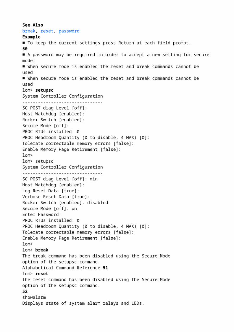
–h Displays help for this command.Alphabetical Command Reference 49Enable/Disable use of the reset and break commands. When Secure Mode isenabled the reset and break commands are disabled. If a password has been setfor the system controller then you are prompted for password confirmation beforea new setting for Secure Mode is accepted.■ Capacity On Demand (COD) headroomConfigure the number of currently installed instant access COD Right-To-Uselicenses (RTU).You can also configure the COD headroom quantity (the number of additionalunlicensed COD CPUs that can be used temporarily). The maximum number ofinstant access CPUs that can be enabled (4) is displayed inside the parentheses.Specify 0 to disable the instant access CPU quantity only if there are no instantaccess CPUs currently in use.The current number of instant access CPUs enabled is displayed inside thebrackets.■ Tolerate correctable memory errors:If set to true it allows the Solaris Operating System to boot with memoryexhibiting correctable ECC errors.The Solaris 10 Operating System incorporates features that automatically isolatefaulty parts of such memory modules, thus avoiding the need to completelydisable these modules and increasing system availability. Setting this option canincrease the time required to complete POST.If set to false, memory modules exhibiting correctable ECC errors are disabled byPOST and not allowed to participate in the Solaris domain.■ Enable Memory Page Retirement:If your version of the Solaris operating system supports memory page retirement,setting this option to true instructs POST to collect statistics about correctableerrors to determine whether a threshold value has been reached, requiring that amemory bank (4 DIMMs) be removed from the domain. The previous option(Tolerate correctable memory errors) ignores all correctable memory errors.When both Tolerate correctable memory errors and Enable Memory PageRetirement options are set, Tolerate correctable memory errors takes precedence.See Alsobreak, reset, passwordExample■ To keep the current settings press Return at each field prompt.50■ A password may be required in order to accept a new setting for secure mode.■ When secure mode is enabled the reset and break commands cannot be used:■ When secure mode is enabled the reset and break commands cannot be used.lom> setupscSystem Controller Configuration-------------------------------SC POST diag Level [off]:Host Watchdog [enabled]:Rocker Switch [enabled]:Secure Mode [off]:PROC RTUs installed: 0PROC Headroom Quantity (0 to disable, 4 MAX) [0]:Tolerate correctable memory errors [false]:Enable Memory Page Retirement [false]:lom>lom> setupscSystem Controller Configuration-------------------------------

SC POST diag Level [off]: minHost Watchdog [enabled]:Log Reset Data [true]:Verbose Reset Data [true]:Rocker Switch [enabled]: disabledSecure Mode [off]: onEnter Password:PROC RTUs installed: 0PROC Headroom Quantity (0 to disable, 4 MAX) [0]:Tolerate correctable memory errors [false]:Enable Memory Page Retirement [false]:lom>lom> breakThe break command has been disabled using the Secure Modeoption of the setupsc command.Alphabetical Command Reference 51lom> resetThe reset command has been disabled using the Secure Modeoption of the setupsc command.52showalarmDisplays state of system alarm relays and LEDs.Syntaxshowalarm 1|2|3|systemshowalarm –hOptions/ParametersThe following table lists all options or parameters and describes their use:DescriptionShow state of system alarm relays and LEDs. For information about the systemalarm and Alarm 3, see Appendix A of the Sun Fire Entry-Level Midrange SystemAdministration Guide.See AlsosetalarmExamples■ To show the state of the system alarm (UNIX running):■ To show the state of alarm 1:1 Shows the state of the alarm 1 LED and relay.2 Shows the state of the alarm 2 LED and relay.3 Shows the state of the alarm 3 LED and relay.system Shows state of system (UNIX running) alarm relay andLED.–h Displays help for this command.lom> showalarm systemsystem alarm is onlom> showalarm 1alarm1 is offAlphabetical Command Reference 53■ To show the state of alarm 2:■ To show the state of alarm 3:lom> showalarm 2alarm2 is offlom> showalarm 3alarm3 is off54showboardsDisplay the status for all boards in the system

Syntaxshowboards [–ev] [–p part] ...showboards –hOptions/ParametersThe following table lists all options or parameters and describes their use:.DescriptionDisplays the status of all of the boards in the system (for example CPU/Memoryboards, I/O assembly, fan tray and so on).–e Includes empty slots.–p Shows a specific part.part can be:• board – Shows board status.• cpu – Shows CPU information.• io – Shows I/O information.• memory – Shows memory information.• serial – Shows board serial number information.• version – Shows version information.–v Displays all information.–h Displays help for this command.Alphabetical Command Reference 55Examples■ To show all boards (same as showboards –p board):■ To show all boards, including empty slots:CODE EXAMPLE 10 Using the showboards Commandlom>showboardsSlot Pwr Component Type State Status---- --- -------------- ----- ------SSC1 On System Controller Main Passed/N0/SCC - System Config Card Assigned OK/N0/BP - Baseplane Assigned OK/N0/SIB - Indicator Board Assigned OK/N0/SPDB - System Power Distribution Bd. Assigned Passed/N0/PS0 On A166 Power Supply - OK/N0/PS1 On A166 Power Supply - OK/N0/FT0 On Fan Tray Auto Speed OK/N0/RP0 On Repeater Board Assigned OK/N0/RP2 On Repeater Board Assigned OK/N0/SB0 On CPU Board Active Passed/N0/IB6 On PCI I/O Board Active Passed/N0/MB - Media Bay Assigned OKCODE EXAMPLE 11 Using the showboards -e Commandlom>showboards -eSlot Pwr Component Type State Status---- --- -------------- ----- ------SSC1 On System Controller Main Passed/N0/SCC - System Config Card Assigned OK/N0/BP - Baseplane Assigned Passed/N0/SIB - Indicator Board Assigned OK/N0/SPDB - System Power Distribution Bd. Assigned Passed/N0/PS0 On A166 Power Supply - OK/N0/PS1 On A166 Power Supply - OKPS2 - Empty Slot Assigned -PS3 - Empty Slot Assigned -/N0/FT0 On Fan Tray Auto Speed Passed/N0/RP0 On Repeater Board Assigned OK/N0/RP2 On Repeater Board Assigned OK

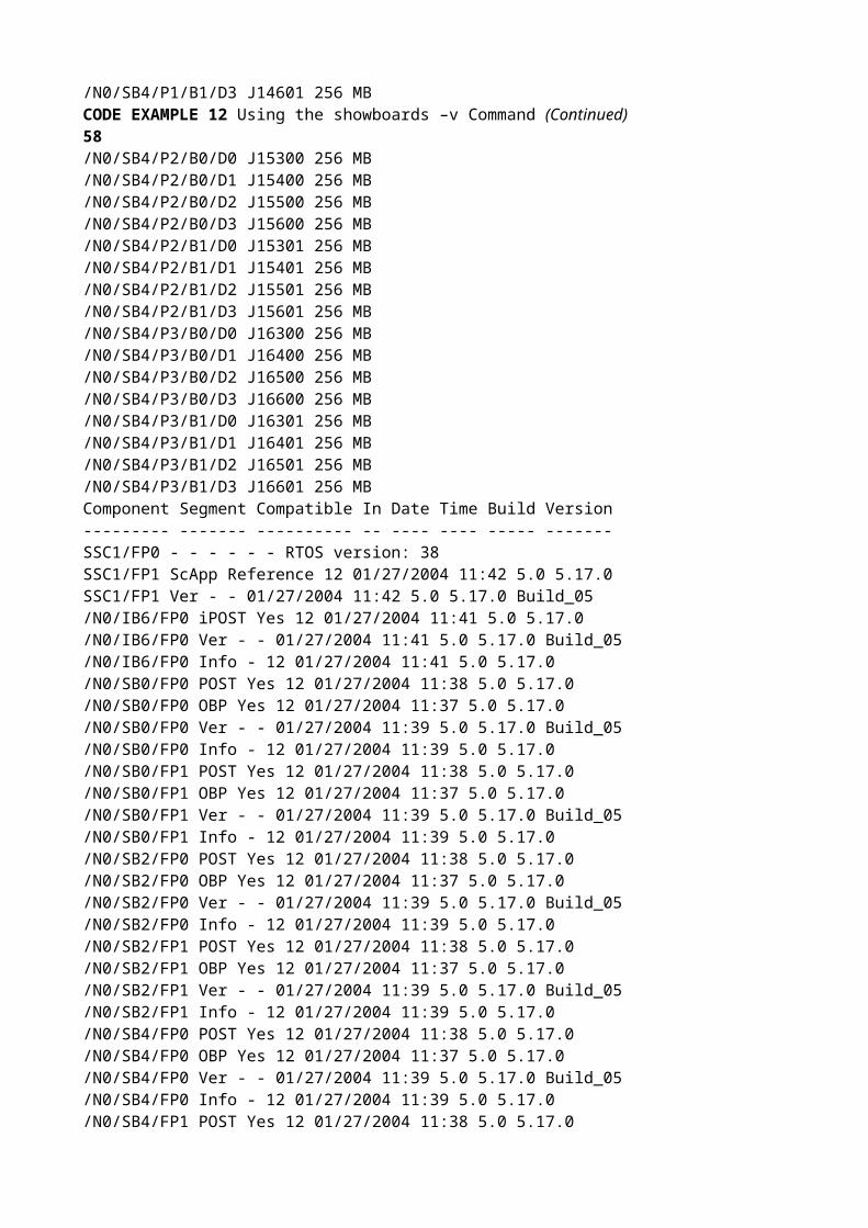
/N0/SB0 On CPU Board Active Passed/N0/SB2 On CPU Board Active PassedSB4 - Empty Slot Assigned -/N0/IB6 On PCI I/O Board Active Passed/N0/MB - Media Bay Assigned OK56■ To show all information about a system’s boards::CODE EXAMPLE 12 Using the showboards –v Commandlom>showboards -vSlot Pwr Component Type State Status---- --- -------------- ----- ------SSC1 On System Controller V2 Main Passed/N0/SCC - System Config Card Assigned OK/N0/BP - Baseplane Assigned Passed/N0/SIB - Indicator Board Assigned Passed/N0/SPDB - System Power Distribution Bd. Assigned Passed/N0/PS0 On A166 Power Supply - OK/N0/PS1 On A166 Power Supply - OK/N0/PS2 On A166 Power Supply - OK/N0/PS3 On A166 Power Supply - OK/N0/FT0 On Fan Tray Auto Speed Passed/N0/RP0 On Repeater Board Assigned OK/N0/RP2 On Repeater Board Assigned OK/N0/SB0 On CPU Board Active Passed/N0/SB2 On CPU Board V3 Active Passed/N0/SB4 On CPU Board Active Passed/N0/IB6 On PCI I/O Board Active Passed/N0/MB - Media Bay Assigned PassedComponent J-No. Size Reason--------- ----- ---- ------/N0/SB0/P0/B0/D0 J13300 256 MB/N0/SB0/P0/B0/D1 J13400 256 MB/N0/SB0/P0/B0/D2 J13500 256 MB/N0/SB0/P0/B0/D3 J13600 256 MB/N0/SB0/P0/B1/D0 J13301 256 MB/N0/SB0/P0/B1/D1 J13401 256 MB/N0/SB0/P0/B1/D2 J13501 256 MB/N0/SB0/P0/B1/D3 J13601 256 MB/N0/SB0/P1/B0/D0 J14300 256 MB/N0/SB0/P1/B0/D1 J14400 256 MB/N0/SB0/P1/B0/D2 J14500 256 MB/N0/SB0/P1/B0/D3 J14600 256 MB/N0/SB0/P1/B1/D0 J14301 256 MB/N0/SB0/P1/B1/D1 J14401 256 MB/N0/SB0/P1/B1/D2 J14501 256 MB/N0/SB0/P1/B1/D3 J14601 256 MB/N0/SB0/P2/B0/D0 J15300 256 MB/N0/SB0/P2/B0/D1 J15400 256 MB/N0/SB0/P2/B0/D2 J15500 256 MB/N0/SB0/P2/B0/D3 J15600 256 MB/N0/SB0/P2/B1/D0 J15301 256 MBAlphabetical Command Reference 57/N0/SB0/P2/B1/D1 J15401 256 MB/N0/SB0/P2/B1/D2 J15501 256 MB/N0/SB0/P2/B1/D3 J15601 256 MB/N0/SB0/P3/B0/D0 J16300 256 MB

/N0/SB0/P3/B0/D1 J16400 256 MB/N0/SB0/P3/B0/D2 J16500 256 MB/N0/SB0/P3/B0/D3 J16600 256 MB/N0/SB0/P3/B1/D0 J16301 256 MB/N0/SB0/P3/B1/D1 J16401 256 MB/N0/SB0/P3/B1/D2 J16501 256 MB/N0/SB0/P3/B1/D3 J16601 256 MB/N0/SB2/P0/B0 - - DRAM DIMM Group 0 Empty/N0/SB2/P0/B1/D0 J13301 512 MB/N0/SB2/P0/B1/D1 J13401 512 MB/N0/SB2/P0/B1/D2 J13501 512 MB/N0/SB2/P0/B1/D3 J13601 512 MB/N0/SB2/P1/B0 - - DRAM DIMM Group 0 Empty/N0/SB2/P1/B1/D0 J14301 512 MB/N0/SB2/P1/B1/D1 J14401 512 MB/N0/SB2/P1/B1/D2 J14501 512 MB/N0/SB2/P1/B1/D3 J14601 512 MB/N0/SB2/P2/B0 - - DRAM DIMM Group 0 Empty/N0/SB2/P2/B1/D0 J15301 512 MB/N0/SB2/P2/B1/D1 J15401 512 MB/N0/SB2/P2/B1/D2 J15501 512 MB/N0/SB2/P2/B1/D3 J15601 512 MB/N0/SB2/P3/B0 - - DRAM DIMM Group 0 Empty/N0/SB2/P3/B1/D0 J16301 512 MB/N0/SB2/P3/B1/D1 J16401 512 MB/N0/SB2/P3/B1/D2 J16501 512 MB/N0/SB2/P3/B1/D3 J16601 512 MB/N0/SB4/P0/B0/D0 J13300 256 MB/N0/SB4/P0/B0/D1 J13400 256 MB/N0/SB4/P0/B0/D2 J13500 256 MB/N0/SB4/P0/B0/D3 J13600 256 MB/N0/SB4/P0/B1/D0 J13301 256 MB/N0/SB4/P0/B1/D1 J13401 256 MB/N0/SB4/P0/B1/D2 J13501 256 MB/N0/SB4/P0/B1/D3 J13601 256 MB/N0/SB4/P1/B0/D0 J14300 256 MB/N0/SB4/P1/B0/D1 J14400 256 MB/N0/SB4/P1/B0/D2 J14500 256 MB/N0/SB4/P1/B0/D3 J14600 256 MB/N0/SB4/P1/B1/D0 J14301 256 MB/N0/SB4/P1/B1/D1 J14401 256 MB/N0/SB4/P1/B1/D2 J14501 256 MB/N0/SB4/P1/B1/D3 J14601 256 MBCODE EXAMPLE 12 Using the showboards –v Command (Continued)58/N0/SB4/P2/B0/D0 J15300 256 MB/N0/SB4/P2/B0/D1 J15400 256 MB/N0/SB4/P2/B0/D2 J15500 256 MB/N0/SB4/P2/B0/D3 J15600 256 MB/N0/SB4/P2/B1/D0 J15301 256 MB/N0/SB4/P2/B1/D1 J15401 256 MB/N0/SB4/P2/B1/D2 J15501 256 MB/N0/SB4/P2/B1/D3 J15601 256 MB/N0/SB4/P3/B0/D0 J16300 256 MB/N0/SB4/P3/B0/D1 J16400 256 MB/N0/SB4/P3/B0/D2 J16500 256 MB

/N0/SB4/P3/B0/D3 J16600 256 MB/N0/SB4/P3/B1/D0 J16301 256 MB/N0/SB4/P3/B1/D1 J16401 256 MB/N0/SB4/P3/B1/D2 J16501 256 MB/N0/SB4/P3/B1/D3 J16601 256 MBComponent Segment Compatible In Date Time Build Version--------- ------- ---------- -- ---- ---- ----- -------SSC1/FP0 - - - - - - RTOS version: 38SSC1/FP1 ScApp Reference 12 01/27/2004 11:42 5.0 5.17.0SSC1/FP1 Ver - - 01/27/2004 11:42 5.0 5.17.0 Build_05/N0/IB6/FP0 iPOST Yes 12 01/27/2004 11:41 5.0 5.17.0/N0/IB6/FP0 Ver - - 01/27/2004 11:41 5.0 5.17.0 Build_05/N0/IB6/FP0 Info - 12 01/27/2004 11:41 5.0 5.17.0/N0/SB0/FP0 POST Yes 12 01/27/2004 11:38 5.0 5.17.0/N0/SB0/FP0 OBP Yes 12 01/27/2004 11:37 5.0 5.17.0/N0/SB0/FP0 Ver - - 01/27/2004 11:39 5.0 5.17.0 Build_05/N0/SB0/FP0 Info - 12 01/27/2004 11:39 5.0 5.17.0/N0/SB0/FP1 POST Yes 12 01/27/2004 11:38 5.0 5.17.0/N0/SB0/FP1 OBP Yes 12 01/27/2004 11:37 5.0 5.17.0/N0/SB0/FP1 Ver - - 01/27/2004 11:39 5.0 5.17.0 Build_05/N0/SB0/FP1 Info - 12 01/27/2004 11:39 5.0 5.17.0/N0/SB2/FP0 POST Yes 12 01/27/2004 11:38 5.0 5.17.0/N0/SB2/FP0 OBP Yes 12 01/27/2004 11:37 5.0 5.17.0/N0/SB2/FP0 Ver - - 01/27/2004 11:39 5.0 5.17.0 Build_05/N0/SB2/FP0 Info - 12 01/27/2004 11:39 5.0 5.17.0/N0/SB2/FP1 POST Yes 12 01/27/2004 11:38 5.0 5.17.0/N0/SB2/FP1 OBP Yes 12 01/27/2004 11:37 5.0 5.17.0/N0/SB2/FP1 Ver - - 01/27/2004 11:39 5.0 5.17.0 Build_05/N0/SB2/FP1 Info - 12 01/27/2004 11:39 5.0 5.17.0/N0/SB4/FP0 POST Yes 12 01/27/2004 11:38 5.0 5.17.0/N0/SB4/FP0 OBP Yes 12 01/27/2004 11:37 5.0 5.17.0/N0/SB4/FP0 Ver - - 01/27/2004 11:39 5.0 5.17.0 Build_05/N0/SB4/FP0 Info - 12 01/27/2004 11:39 5.0 5.17.0/N0/SB4/FP1 POST Yes 12 01/27/2004 11:38 5.0 5.17.0CODE EXAMPLE 12 Using the showboards –v Command (Continued)Alphabetical Command Reference 59/N0/SB4/FP1 OBP Yes 12 01/27/2004 11:37 5.0 5.17.0/N0/SB4/FP1 Ver - - 01/27/2004 11:39 5.0 5.17.0 Build_05/N0/SB4/FP1 Info - 12 01/27/2004 11:39 5.0 5.17.0Slot Populated Slot Description---- --------- ----------------/N0/IB6/P0/B1/C0 Empty 33MHz. 5V Short PCI card/N0/IB6/P0/B1/C1 Empty 33MHz. 5V Short PCI card/N0/IB6/P1/B1/C2 Empty 33MHz. 5V Short PCI card/N0/IB6/P1/B1/C3 Empty 33MHz. 5V Short PCI card/N0/IB6/P1/B1/C4 Empty 33MHz. 5V Short PCI card/N0/IB6/P0/B0/C5 Empty 66/33MHz. 3.3V Short PCI cardComponent Part # Serial # Description--------- ------ -------- -----------/N0/SB0 540-5467-01-50 001004 CPU Board (1280)/N0/SB4 540-5467-01-50 000096 CPU Board (1280)/N0/SB0/P0/B0/D0 501-5401-03-50 KD0W2F 256 MB NG SDRAM DIMM/N0/SB0/P0/B0/D1 501-5401-03-50 KD0W2K 256 MB NG SDRAM DIMM/N0/SB0/P0/B0/D2 501-5401-03-50 KD0W2P 256 MB NG SDRAM DIMM/N0/SB0/P0/B0/D3 501-5401-03-50 KD0W2W 256 MB NG SDRAM DIMM/N0/SB0/P0/B1/D0 501-5401-03-50 KD0W2N 256 MB NG SDRAM DIMM

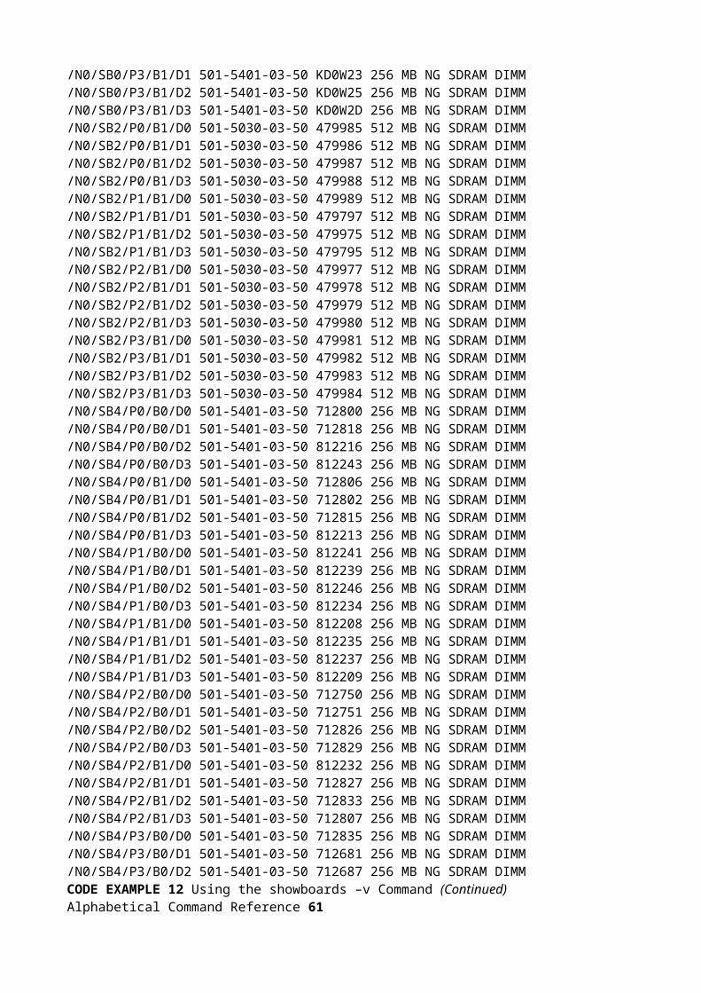
/N0/SB0/P0/B1/D1 501-5401-03-50 KD0W2R 256 MB NG SDRAM DIMM/N0/SB0/P0/B1/D2 501-5401-03-50 KD0W2T 256 MB NG SDRAM DIMM/N0/SB0/P0/B1/D3 501-5401-03-50 KD0W0T 256 MB NG SDRAM DIMM/N0/SB0/P1/B0/D0 501-5401-03-50 KD0W3B 256 MB NG SDRAM DIMM/N0/SB0/P1/B0/D1 501-5401-03-50 KD0W1Q 256 MB NG SDRAM DIMM/N0/SB0/P1/B0/D2 501-5401-03-50 KD0W05 256 MB NG SDRAM DIMM/N0/SB0/P1/B0/D3 501-5401-03-50 KD24GK 256 MB NG SDRAM DIMM/N0/SB0/P1/B1/D0 501-5401-03-50 KD0W3C 256 MB NG SDRAM DIMM/N0/SB0/P1/B1/D1 501-5401-03-50 KD0W35 256 MB NG SDRAM DIMM/N0/SB0/P1/B1/D2 501-5401-03-50 KD0VZX 256 MB NG SDRAM DIMM/N0/SB0/P1/B1/D3 501-5401-03-50 KD0W1W 256 MB NG SDRAM DIMM/N0/SB0/P2/B0/D0 501-5401-03-50 KD0W1R 256 MB NG SDRAM DIMM/N0/SB0/P2/B0/D1 501-5401-03-50 KD0W0G 256 MB NG SDRAM DIMM/N0/SB0/P2/B0/D2 501-5401-03-50 KD0VZQ 256 MB NG SDRAM DIMM/N0/SB0/P2/B0/D3 501-5401-03-50 KD0W24 256 MB NG SDRAM DIMM/N0/SB0/P2/B1/D0 501-5401-03-50 KD0W1V 256 MB NG SDRAM DIMM/N0/SB0/P2/B1/D1 501-5401-03-50 KD0W07 256 MB NG SDRAM DIMM/N0/SB0/P2/B1/D2 501-5401-03-50 KD0W0B 256 MB NG SDRAM DIMM/N0/SB0/P2/B1/D3 501-5401-03-50 KD0W1X 256 MB NG SDRAM DIMM/N0/SB0/P3/B0/D0 501-5401-03-50 KD0W1Y 256 MB NG SDRAM DIMM/N0/SB0/P3/B0/D1 501-5401-03-50 KD0W20 256 MB NG SDRAM DIMM/N0/SB0/P3/B0/D2 501-5401-03-50 KD0W2B 256 MB NG SDRAM DIMM/N0/SB0/P3/B0/D3 501-5401-03-50 KD0W27 256 MB NG SDRAM DIMMCODE EXAMPLE 12 Using the showboards –v Command (Continued)60/N0/SB0/P3/B1/D0 501-5401-03-50 KD0W1Z 256 MB NG SDRAM DIMM/N0/SB0/P3/B1/D1 501-5401-03-50 KD0W23 256 MB NG SDRAM DIMM/N0/SB0/P3/B1/D2 501-5401-03-50 KD0W25 256 MB NG SDRAM DIMM/N0/SB0/P3/B1/D3 501-5401-03-50 KD0W2D 256 MB NG SDRAM DIMM/N0/SB2/P0/B1/D0 501-5030-03-50 479985 512 MB NG SDRAM DIMM/N0/SB2/P0/B1/D1 501-5030-03-50 479986 512 MB NG SDRAM DIMM/N0/SB2/P0/B1/D2 501-5030-03-50 479987 512 MB NG SDRAM DIMM/N0/SB2/P0/B1/D3 501-5030-03-50 479988 512 MB NG SDRAM DIMM/N0/SB2/P1/B1/D0 501-5030-03-50 479989 512 MB NG SDRAM DIMM/N0/SB2/P1/B1/D1 501-5030-03-50 479797 512 MB NG SDRAM DIMM/N0/SB2/P1/B1/D2 501-5030-03-50 479975 512 MB NG SDRAM DIMM/N0/SB2/P1/B1/D3 501-5030-03-50 479795 512 MB NG SDRAM DIMM/N0/SB2/P2/B1/D0 501-5030-03-50 479977 512 MB NG SDRAM DIMM/N0/SB2/P2/B1/D1 501-5030-03-50 479978 512 MB NG SDRAM DIMM/N0/SB2/P2/B1/D2 501-5030-03-50 479979 512 MB NG SDRAM DIMM/N0/SB2/P2/B1/D3 501-5030-03-50 479980 512 MB NG SDRAM DIMM/N0/SB2/P3/B1/D0 501-5030-03-50 479981 512 MB NG SDRAM DIMM/N0/SB2/P3/B1/D1 501-5030-03-50 479982 512 MB NG SDRAM DIMM/N0/SB2/P3/B1/D2 501-5030-03-50 479983 512 MB NG SDRAM DIMM/N0/SB2/P3/B1/D3 501-5030-03-50 479984 512 MB NG SDRAM DIMM/N0/SB4/P0/B0/D0 501-5401-03-50 712800 256 MB NG SDRAM DIMM/N0/SB4/P0/B0/D1 501-5401-03-50 712818 256 MB NG SDRAM DIMM/N0/SB4/P0/B0/D2 501-5401-03-50 812216 256 MB NG SDRAM DIMM/N0/SB4/P0/B0/D3 501-5401-03-50 812243 256 MB NG SDRAM DIMM/N0/SB4/P0/B1/D0 501-5401-03-50 712806 256 MB NG SDRAM DIMM/N0/SB4/P0/B1/D1 501-5401-03-50 712802 256 MB NG SDRAM DIMM/N0/SB4/P0/B1/D2 501-5401-03-50 712815 256 MB NG SDRAM DIMM/N0/SB4/P0/B1/D3 501-5401-03-50 812213 256 MB NG SDRAM DIMM/N0/SB4/P1/B0/D0 501-5401-03-50 812241 256 MB NG SDRAM DIMM/N0/SB4/P1/B0/D1 501-5401-03-50 812239 256 MB NG SDRAM DIMM/N0/SB4/P1/B0/D2 501-5401-03-50 812246 256 MB NG SDRAM DIMM

/N0/SB4/P1/B0/D3 501-5401-03-50 812234 256 MB NG SDRAM DIMM/N0/SB4/P1/B1/D0 501-5401-03-50 812208 256 MB NG SDRAM DIMM/N0/SB4/P1/B1/D1 501-5401-03-50 812235 256 MB NG SDRAM DIMM/N0/SB4/P1/B1/D2 501-5401-03-50 812237 256 MB NG SDRAM DIMM/N0/SB4/P1/B1/D3 501-5401-03-50 812209 256 MB NG SDRAM DIMM/N0/SB4/P2/B0/D0 501-5401-03-50 712750 256 MB NG SDRAM DIMM/N0/SB4/P2/B0/D1 501-5401-03-50 712751 256 MB NG SDRAM DIMM/N0/SB4/P2/B0/D2 501-5401-03-50 712826 256 MB NG SDRAM DIMM/N0/SB4/P2/B0/D3 501-5401-03-50 712829 256 MB NG SDRAM DIMM/N0/SB4/P2/B1/D0 501-5401-03-50 812232 256 MB NG SDRAM DIMM/N0/SB4/P2/B1/D1 501-5401-03-50 712827 256 MB NG SDRAM DIMM/N0/SB4/P2/B1/D2 501-5401-03-50 712833 256 MB NG SDRAM DIMM/N0/SB4/P2/B1/D3 501-5401-03-50 712807 256 MB NG SDRAM DIMM/N0/SB4/P3/B0/D0 501-5401-03-50 712835 256 MB NG SDRAM DIMM/N0/SB4/P3/B0/D1 501-5401-03-50 712681 256 MB NG SDRAM DIMM/N0/SB4/P3/B0/D2 501-5401-03-50 712687 256 MB NG SDRAM DIMMCODE EXAMPLE 12 Using the showboards –v Command (Continued)Alphabetical Command Reference 61/N0/SB4/P3/B0/D3 501-5401-03-50 712803 256 MB NG SDRAM DIMM/N0/SB4/P3/B1/D0 501-5401-03-50 712808 256 MB NG SDRAM DIMM/N0/SB4/P3/B1/D1 501-5401-03-50 712810 256 MB NG SDRAM DIMM/N0/SB4/P3/B1/D2 501-5401-03-50 712683 256 MB NG SDRAM DIMM/N0/SB4/P3/B1/D3 501-5401-03-50 712688 256 MB NG SDRAM DIMM/N0/SB0/P0/E0 370-4128-03-50 4A5TDM 4MB Ecache Module/N0/SB0/P0/E1 370-4128-03-50 4A5TBD 4MB Ecache Module/N0/SB0/P1/E0 370-4128-03-50 4A5TBB 4MB Ecache Module/N0/SB0/P1/E1 370-4128-03-50 4A5TDN 4MB Ecache Module/N0/SB0/P2/E0 370-4128-03-50 4A5TBG 4MB Ecache Module/N0/SB0/P2/E1 370-4128-03-50 4A5TBJ 4MB Ecache Module/N0/SB0/P3/E0 370-4128-03-50 4A5TDY 4MB Ecache Module/N0/SB0/P3/E1 370-4128-03-50 4A5TDV 4MB Ecache Module/N0/SB2/P0/E0 370-4129-01-01 2APK8W 8MB Ecache Module/N0/SB2/P0/E1 370-4129-01-01 2APK9D 8MB Ecache Module/N0/SB2/P1/E0 370-4129-01-01 2APK91 8MB Ecache Module/N0/SB2/P1/E1 370-4129-01-01 2APK97 8MB Ecache Module/N0/SB2/P2/E0 370-4129-01-01 2APK95 8MB Ecache Module/N0/SB2/P2/E1 370-4129-01-01 2APK87 8MB Ecache Module/N0/SB2/P3/E0 370-4129-01-01 2APKA7 8MB Ecache Module/N0/SB2/P3/E1 370-4129-01-01 2APKA5 8MB Ecache Module/N0/SB4/P0/E0 370-4128-03-50 4A57JT 4MB Ecache Module/N0/SB4/P0/E1 370-4128-03-50 4A580U 4MB Ecache Module/N0/SB4/P1/E0 370-4128-03-50 4A580Y 4MB Ecache Module/N0/SB4/P1/E1 370-4128-03-50 4A57ZT 4MB Ecache Module/N0/SB4/P2/E0 370-4128-03-50 4A57JK 4MB Ecache Module/N0/SB4/P2/E1 370-4128-03-50 4A57HP 4MB Ecache Module/N0/SB4/P3/E0 370-4128-03-50 4A57HG 4MB Ecache Module/N0/SB4/P3/E1 370-4128-03-50 4A57HV 4MB Ecache Module/N0/SB2 501-6520-02-01 A00065 CPU Board V3/N0/IB6 540-5564-01-01 A08712 IB_SSC Assembly (1280)Component Cpu Mask Description--------- -------- -----------/N0/SB0/P0 2.2 UltraSPARC-III+, 660MHz, 8M ECache/N0/SB0/P1 2.2 UltraSPARC-III+, 660MHz, 8M ECache/N0/SB0/P2 2.2 UltraSPARC-III+, 660MHz, 8M ECache/N0/SB0/P3 2.2 UltraSPARC-III+, 660MHz, 8M ECache/N0/SB2/P0 1.1 UltraSPARC-IV, 660MHz, 16M ECache
/N0/SB2/P1 1.1 UltraSPARC-IV, 660MHz, 16M ECache/N0/SB2/P2 1.1 UltraSPARC-IV, 660MHz, 16M ECache/N0/SB2/P3 1.1 UltraSPARC-IV, 660MHz, 16M ECache/N0/SB4/P0 6.0 UltraSPARC-III+, 660MHz, 8M ECache/N0/SB4/P1 6.0 UltraSPARC-III+, 660MHz, 8M ECache/N0/SB4/P2 6.0 UltraSPARC-III+, 660MHz, 8M ECache/N0/SB4/P3 6.0 UltraSPARC-III+, 660MHz, 8M ECacheCODE EXAMPLE 12 Using the showboards –v Command (Continued)62■ To show memory information for boards:■ To show the version of each board:■ To show I/O information for boards:■ To show board serial number information:CODE EXAMPLE 13 Using the showboards –p memory Commandlom>showboards –p memoryComponent Size Reason--------- ---- ------/N0/SB0 8192 MB/N0/SB2 8192 MBCODE EXAMPLE 14 Using the showboards –p version Commandlom>showboards –p versionComponent Compatible Version--------- ---------- -------SSC1 Reference 5.17.0 Build_05/N0/IB6 Yes 5.17.0 Build_05/N0/SB0 Yes 5.17.0 Build_05/N0/SB2 Yes 5.17.0 Build_05/N0/SB4 Yes 5.17.0 Build_05CODE EXAMPLE 15 Using the showboards –p io Commandlom>showboards –p ioSlot Populated Slot Description---- --------- ----------------/N0/IB6/P0/B1/C0 Empty 33MHz. 5V Short PCI card/N0/IB6/P0/B1/C1 Empty 33MHz. 5V Short PCI card/N0/IB6/P1/B1/C2 Empty 33MHz. 5V Short PCI card/N0/IB6/P1/B1/C3 Empty 33MHz. 5V Short PCI card/N0/IB6/P1/B1/C4 Empty 33MHz. 5V Short PCI card/N0/IB6/P0/B0/C5 Empty 66/33MHz. 3.3V Short PCI cardCODE EXAMPLE 16 Using the showboards –p serial Commandlom>showboards –p serialComponent Part # Serial # Description--------- ------ -------- -----------/N0/SB0 501-4362-08-50 013362 CPU Board/N0/SB2 501-4362-08-50 014812 CPU BoardAlphabetical Command Reference 63/N0/SB0/P0/B0/D0 501-5030-02-50 428079 512 MB NG SDRAM DIMM/N0/SB0/P0/B0/D1 501-5030-02-50 428080 512 MB NG SDRAM DIMM/N0/SB0/P0/B0/D2 501-5030-02-50 428081 512 MB NG SDRAM DIMM/N0/SB0/P0/B0/D3 501-5030-02-50 428082 512 MB NG SDRAM DIMM/N0/SB0/P1/B0/D0 501-5030-02-01 010398 512 MB NG SDRAM DIMM/N0/SB0/P1/B0/D1 501-5030-02-01 010486 512 MB NG SDRAM DIMM/N0/SB0/P1/B0/D2 501-5030-02-01 010400 512 MB NG SDRAM DIMM/N0/SB0/P1/B0/D3 501-5030-02-01 010392 512 MB NG SDRAM DIMM/N0/SB0/P2/B0/D0 501-5030-02-50 072411 512 MB NG SDRAM DIMM/N0/SB0/P2/B0/D1 501-5030-02-50 428072 512 MB NG SDRAM DIMM/N0/SB0/P2/B0/D2 501-5030-02-50 428073 512 MB NG SDRAM DIMM

/N0/SB0/P2/B0/D3 501-5030-02-50 428074 512 MB NG SDRAM DIMM/N0/SB0/P3/B0/D0 501-5030-02-50 428075 512 MB NG SDRAM DIMM/N0/SB0/P3/B0/D1 501-5030-02-50 428076 512 MB NG SDRAM DIMM/N0/SB0/P3/B0/D2 501-5030-02-50 428077 512 MB NG SDRAM DIMM/N0/SB0/P3/B0/D3 501-5030-02-50 428078 512 MB NG SDRAM DIMM/N0/SB2/P0/B1/D0 501-5030-02-50 072392 512 MB NG SDRAM DIMM/N0/SB2/P0/B1/D1 501-5030-02-50 072403 512 MB NG SDRAM DIMM/N0/SB2/P0/B1/D2 501-5030-02-50 072399 512 MB NG SDRAM DIMM/N0/SB2/P0/B1/D3 501-5030-02-50 072396 512 MB NG SDRAM DIMM/N0/SB2/P1/B1/D0 501-5030-02-50 072388 512 MB NG SDRAM DIMM/N0/SB2/P1/B1/D1 501-5030-02-50 072273 512 MB NG SDRAM DIMM/N0/SB2/P1/B1/D2 501-5030-02-50 072398 512 MB NG SDRAM DIMM/N0/SB2/P1/B1/D3 501-5030-02-50 072394 512 MB NG SDRAM DIMM/N0/SB2/P2/B1/D0 501-5030-02-50 072395 512 MB NG SDRAM DIMM/N0/SB2/P2/B1/D1 501-5030-02-50 072393 512 MB NG SDRAM DIMM/N0/SB2/P2/B1/D2 501-5030-02-50 072406 512 MB NG SDRAM DIMM/N0/SB2/P2/B1/D3 501-5030-02-50 072410 512 MB NG SDRAM DIMM/N0/SB2/P3/B1/D0 501-5030-02-50 072402 512 MB NG SDRAM DIMM/N0/SB2/P3/B1/D1 501-5030-02-50 072404 512 MB NG SDRAM DIMM/N0/SB2/P3/B1/D2 501-5030-02-50 072400 512 MB NG SDRAM DIMM/N0/SB2/P3/B1/D3 501-5030-02-50 072397 512 MB NG SDRAM DIMM/N0/SB0/P0/E0 370-4125-01-01 498D2H 4MB Ecache Module/N0/SB0/P0/E1 370-4125-01-01 498BUW 4MB Ecache Module/N0/SB0/P1/E0 370-4125-01-01 498BD0 4MB Ecache Module/N0/SB0/P1/E1 370-4125-01-01 498D1D 4MB Ecache Module/N0/SB0/P2/E0 370-4125-01-01 498BTV 4MB Ecache Module/N0/SB0/P2/E1 370-4125-01-01 498BKY 4MB Ecache Module/N0/SB0/P3/E0 370-4125-01-01 498AYK 4MB Ecache Module/N0/SB0/P3/E1 370-4125-01-01 498BU6 4MB Ecache Module/N0/SB2/P0/E0 370-4125-01-01 4950NH 4MB Ecache Module/N0/SB2/P0/E1 370-4125-01-01 4951EZ 4MB Ecache Module/N0/SB2/P1/E0 370-4125-01-01 494XTW 4MB Ecache Module/N0/SB2/P1/E1 370-4125-01-01 495581 4MB Ecache Module/N0/SB2/P2/E0 370-4125-01-01 4951NN 4MB Ecache Module/N0/SB2/P2/E1 370-4125-01-01 4951AV 4MB Ecache ModuleCODE EXAMPLE 16 Using the showboards –p serial Command (Continued)64■ To show CPU information:/N0/SB2/P3/E0 370-4125-01-01 4951DK 4MB Ecache Module/N0/SB2/P3/E1 370-4125-01-01 4950P0 4MB Ecache Module/N0/IB6 000-0000-01-01 6543 PCI I/O BoardCODE EXAMPLE 17 Using the showboards –p cpu Commandlom>showboards –p cpuComponent Description--------- -----------/N0/SB0/P0 UltraSPARC-III+, 900MHz, 8M ECache/N0/SB0/P1 UltraSPARC-III+, 900MHz, 8M ECache/N0/SB0/P2 UltraSPARC-III+, 900MHz, 8M ECache/N0/SB0/P3 UltraSPARC-III+, 900MHz, 8M ECache/N0/SB2/P0 UltraSPARC-III+, 900MHz, 8M ECache/N0/SB2/P1 UltraSPARC-III+, 900MHz, 8M ECache/N0/SB2/P2 UltraSPARC-III+, 900MHz, 8M ECache/N0/SB2/P3 UltraSPARC-III+, 900MHz, 8M ECacheTABLE 7 Output Header Definitions for the showboards CommandHeader DescriptionSlot Slot designator. The N0 preceding the slot designator for CPU/Memory boards

and I/O assemblies is the node number, which is always 0.Pwr Indicates if the FRU is powered off or on.Component type Describes the board attached to each slot.FRU state Describes FRU state (see TABLE 2).Test status Describes test status (see TABLE 3).CODE EXAMPLE 16 Using the showboards –p serial Command (Continued)Alphabetical Command Reference 65showcodlicenseDisplays the current Capacity on Demand (COD) right-to-use (RTU) licenses storedin the COD license database.Syntaxshowcodlicense [-r] [-v]showcodlicense -hOptions/ParametersThe following table lists all options or parameters and describes their use:DescriptionTABLE 8 describes the default COD information displayed by the showcodlicensecommand.See Alsoaddcodlicense, deletecodlicense, showcodusage-r Displays the license information in the raw license key format, asstored in the COD license database.-v Verbose mode. Displays both the formatted licenseinformation and raw license key format.-h Displays help for this command.TABLE 8 COD License InformationItem DescriptionDescription Type of resource (processor)Ver Version number of the licenseExpiration None. Not supported (no expiration date)Count Number of RTU licenses granted for the given resourceStatus One of the following states:• GOOD – Indicates the resource license is valid• EXPIRED – Indicates the resource license is no longer valid66Examples■ To show formatted COD RTU license key data:■ To show COD RTU license keys:■ To show COD RTU license key data in both formatted and raw format:CODE EXAMPLE 18 showcodlicense Example Output – Formatted COD RTU LicenseDatalom> showcodlicenseDescription Ver Expiration Count Status----------- --- ---------- ----- ------PROC 01 NONE 4 GOODCODE EXAMPLE 19 showcodlicense -r Example Output – COD RTU License Keyslom> showcodlicense -r01:83198b89:001:0201000000:4:00000000:E4pE0udO78XFReGXQd88XgCODE EXAMPLE 20 showcodlicense -v Example Output – Formatted and Raw COD RTU License Datalom> showcodlicense -vDescription Ver Expiration Count Status----------- --- ---------- ----- ------PROC 01 NONE 4 GOOD01:83198b89:001:0201000000:4:00000000:E4pE0udO78XFReGXQd88Xg

Alphabetical Command Reference 67showcodusageDisplays the current usage statistics for Capacity on Demand (COD) resources.Syntaxshowcodusage [-v] [-p domains|all] ...showcodusage -hOptions/ParametersThe following table lists all options or parameters and describes their use:DescriptionThis command shows current information on the COD RTU licenses in use. Bydefault, the command displays a summary of COD RTU licenses used and installed,along with the current state of each resource.See AlsoshowcodlicenseExamples■ To show information by domain, type:-p domains Displays COD usage information for the CPUs that arepart of the Solaris domain.-p all Displays COD usage information both by resource type andby domain.-v Verbose mode.-h Displays help for this command.CODE EXAMPLE 21 showcodusage Example Output by Domainlom> showcodusage –v -p domainsDomain/Resource In Use Installed Reserved Status--------------- ------ --------- -------- ------A - PROC 4 4 0SB0 - PROC 4 4/N0/SB0/P0 Licensed/N0/SB0/P1 Licensed/N0/SB0/P2 Licensed68TABLE 9 describes the domain information displayed.■ To show information by both resource type and domain:/N0/SB0/P3 LicensedUnused - PROC 0 0 0TABLE 9 showcodusage Domain InformationItem DescriptionDomain/Resource The COD resource (processor) for each domain. An unusedprocessor is a COD CPU that has not yet been assigned to a domain.In Use The number of COD CPUs currently used in the domainInstalled The number of COD CPUs installed in the domainReserved The number of COD RTU licenses allocated to the domainStatus One of the following CPU states:• Licensed – The COD CPU has an RTU license.• Unused – The COD CPU is not in use.• Unlicensed – A COD RTU license could not be obtained for theCOD CPU, so the COD CPU cannot be used.CODE EXAMPLE 22 showcodusage Example Output by Both Resource and Domainlom> showcodusage -vResource In Use Installed Licensed Status-------- ------ --------- -------- ------PROC 4 4 0/N0/SB0/P0 Licensed/N0/SB0/P1 Licensed/N0/SB0/P2 Licensed

/N0/SB0/P3 LicensedUnused - PROC 0 0 0CODE EXAMPLE 21 showcodusage Example Output by Domain (Continued)Alphabetical Command Reference 69showcomponentDisplay a component or a list of components.Syntaxshowcomponent [–v] component-name [ component-name . . . ]showcomponent –hOptions/ParametersThe following table lists all options or parameters and describes their use:–v Verbose.component-name The name of the board, as shown in TABLE 10.–h displays help for this command. Includes component-namesyntax.TABLE 10 Descriptions for the showcomponent CommandComponent Description Value of component-nameCPU system slotCPU/Memory boards (slot) sb0, sb2, sb4Ports on the CPU/Memory board p0, p1, p2, p3Physical memory banks on CPU/Memoryboardsb0, b1Logical banks on CPU/Memory boards l0, l1, l2, l3Repeater system slotRepeater boards rp0, rp2I/O assembly system slotI/O assemblies (slot) ib6Ports on the I/O assembly p0, p1Busses on the I/O assembly b0, b1I/O cards in the I/O assembly c0, c1, c2, c3, c4, c570DescriptionDisplays a component or a list of components, together with their POST andblacklist status. The Status column shows the current blacklist status of thecomponent. The Pending column displays the requested blacklist status of thecomponent to be activated after the next reboot or Dynamic Reconfiguration of thatcomponent. The POST column shows the results of the most recent POST.Note – When a Repeater board has been blacklisted using the disablecomponentcommand or removed from the blacklist using the enablecomponent commandwhile the system is in Standby mode, these changes will not be reflected in theshowcomponent output until the system is powered on again.See Also■ enablecomponent■ disablecomponent■ Sun Fire Entry-Level Midrange System Administration Guide (for a step-by-stepprocedure on displaying a component).Examples■ To display a list of components for slot sb0:CODE EXAMPLE 23 Using the showcomponent Command for a CPU/Memory Boardlom>showcomponent sb0Component Status Pending POST Description--------- ------ ------- ---- -----------/N0/SB0/P0 enabled - pass UltraSPARC-III, 750MHz, 8M ECache/N0/SB0/P1 enabled - pass UltraSPARC-III, 750MHz, 8M ECache/N0/SB0/P2 enabled - pass UltraSPARC-III, 750MHz, 8M ECache
/N0/SB0/P3 enabled - pass UltraSPARC-III, 750MHz, 8M ECache/N0/SB0/P0/B0/L0 enabled - pass 512M DRAM/N0/SB0/P0/B0/L2 enabled - pass 512M DRAM/N0/SB0/P0/B1/L1 enabled - untest empty/N0/SB0/P0/B1/L3 enabled - untest empty/N0/SB0/P1/B0/L0 enabled - pass 512M DRAM/N0/SB0/P1/B0/L2 enabled - pass 512M DRAM/N0/SB0/P1/B1/L1 enabled - untest empty/N0/SB0/P1/B1/L3 enabled - untest empty/N0/SB0/P2/B0/L0 enabled - pass 512M DRAM/N0/SB0/P2/B0/L2 enabled - pass 512M DRAM/N0/SB0/P2/B1/L1 enabled - untest empty/N0/SB0/P2/B1/L3 enabled - untest empty/N0/SB0/P3/B0/L0 enabled - pass 512M DRAM/N0/SB0/P3/B0/L2 enabled - pass 512M DRAM/N0/SB0/P3/B1/L1 enabled - untest empty/N0/SB0/P3/B1/L3 enabled - untest emptyAlphabetical Command Reference 71■ To display a list of components for ib6:CODE EXAMPLE 24 Using the showcomponent Command for the IB6 Subassembly of the IB_SSC FRUlom> showcomp ib6Component Status Pending POST Description--------- ------ ------- ---- -----------/N0/IB6/P0 enabled - untest IO Controller 0/N0/IB6/P1 enabled - untest IO Controller 1/N0/IB6/P0/B0 enabled - untest 66/33MHz. PCI Bus/N0/IB6/P0/B1 enabled - untest 33MHz. PCI Bus/N0/IB6/P1/B0 enabled - untest 66/33MHz. PCI Bus/N0/IB6/P1/B1 enabled - untest 33MHz. PCI Bus/N0/IB6/P0/B1/C0 enabled - untest 33MHz. 5V Short PCI card/N0/IB6/P0/B1/C1 enabled - untest 33MHz. 5V Short PCI card/N0/IB6/P1/B1/C2 enabled - untest 33MHz. 5V Short PCI card/N0/IB6/P1/B1/C3 enabled - untest 33MHz. 5V Short PCI card/N0/IB6/P1/B1/C4 enabled - untest 33MHz. 5V Short PCI card/N0/IB6/P0/B0/C5 enabled - untest 66/33MHz. 3.3V Short PCI card72showdateDisplays the current date and time for the system.Syntaxshowdate [–tv]showdate –hOptions/ParametersThe following table lists all options or parameters and describes their use:DescriptionShows the current date and time for the system, or if –t –v is selected then lists allavailable timezones.See AlsosetdateExample–v Verbose.–t Lists available time zones.–h Displays help for this command.CODE EXAMPLE 25 Using the showdate Commandlom> showdateMon Apr 03 12:31:40 EDT 2000

Alphabetical Command Reference 73showenvironmentDisplays the current environmental status, temperatures, voltages, fan status, and soon, for the system.Syntaxshowenvironment [–ltuvw] [–p part] [component]showenvironment [–ltuvw] [component]showenvironment –hOptions/ParametersThe following table lists all options or parameters and describes their use:DescriptionDisplays the current environmental status, temperatures, voltages, fan status, and soon, for the system.–l Shows the thresholds that apply to each selectedmeasurement. Exceeding the thresholds will cause thestatus to display appropriate warning information.–t Shows in sections (by board) with titles.–u Before displaying readings, polls all sensors for newvalues.–v Verbose mode.–w Shows the warning thresholds that apply to each selectedmeasurement.–p Shows a specific part.part can be:• faults – Show measurements that are suspect.• temps – Show temperatures.• voltage – Show voltages.• fans – Show fan status.component The name of the FRU. Displays information for this FRUonly.–h Displays help for this command.74This command also displays minimum and maximum allowable values for eachsensor being monitored. If no arguments are supplied, all applicable environmentalinformation will be displayed.Alphabetical Command Reference 75Example■ To display the current status for all devices in a system:CODE EXAMPLE 26 Using the showenvironment Commandlom> showenvironmentSlot Device Sensor Value Units Age Status---- --------- --------- ------ --------- ------- ------SSC1 SBBC 0 Temp. 0 37 Degrees C 1 sec OKSSC1 CBH 0 Temp. 0 45 Degrees C 1 sec OKSSC1 Board 0 Temp. 0 24 Degrees C 1 sec OKSSC1 Board 0 Temp. 1 22 Degrees C 1 sec OKSSC1 Board 0 Temp. 2 28 Degrees C 1 sec OKSSC1 Board 0 1.5 VDC 0 1.49 Volts DC 1 sec OKSSC1 Board 0 3.3 VDC 0 3.35 Volts DC 1 sec OKSSC1 Board 0 5 VDC 0 5.01 Volts DC 1 sec OK/N0/PS0 Input 0 Volt. 0 - - 6 sec OK/N0/PS0 48 VDC 0 Volt. 0 48.00 Volts DC 6 sec OK/N0/PS1 Input 0 Volt. 0 - - 5 sec OK/N0/PS1 48 VDC 0 Volt. 0 48.00 Volts DC 5 sec OK/N0/FT0 Fan 0 Cooling 0 Auto 5 sec OK/N0/FT0 Fan 1 Cooling 0 Auto 5 sec OK
/N0/FT0 Fan 2 Cooling 0 Auto 5 sec OK/N0/FT0 Fan 3 Cooling 0 Auto 5 sec OK/N0/FT0 Fan 4 Cooling 0 Auto 5 sec OK/N0/FT0 Fan 5 Cooling 0 Auto 5 sec OK/N0/FT0 Fan 6 Cooling 0 Auto 5 sec OK/N0/FT0 Fan 7 Cooling 0 Auto 5 sec OK/N0/RP0 Board 0 1.5 VDC 0 1.51 Volts DC 5 sec OK/N0/RP0 Board 0 3.3 VDC 0 3.35 Volts DC 5 sec OK/N0/RP0 Board 0 Temp. 0 22 Degrees C 5 sec OK/N0/RP0 Board 0 Temp. 1 22 Degrees C 5 sec OK/N0/RP0 SDC 0 Temp. 0 63 Degrees C 5 sec OK/N0/RP0 AR 0 Temp. 0 47 Degrees C 5 sec OK/N0/RP0 DX 0 Temp. 0 62 Degrees C 5 sec OK/N0/RP0 DX 1 Temp. 0 66 Degrees C 5 sec OK/N0/RP2 Board 0 1.5 VDC 0 1.49 Volts DC 4 sec OK/N0/RP2 Board 0 3.3 VDC 0 3.33 Volts DC 4 sec OK/N0/RP2 Board 0 Temp. 0 24 Degrees C 5 sec OK/N0/RP2 Board 0 Temp. 1 23 Degrees C 5 sec OK/N0/RP2 SDC 0 Temp. 0 57 Degrees C 5 sec OK/N0/RP2 AR 0 Temp. 0 42 Degrees C 5 sec OK/N0/RP2 DX 0 Temp. 0 53 Degrees C 5 sec OK/N0/RP2 DX 1 Temp. 0 56 Degrees C 5 sec OK/N0/SB0 Board 0 1.5 VDC 0 1.50 Volts DC 4 sec OK/N0/SB0 Board 0 3.3 VDC 0 3.33 Volts DC 5 sec OK/N0/SB0 SDC 0 Temp. 0 49 Degrees C 5 sec OK76/N0/SB0 AR 0 Temp. 0 39 Degrees C 5 sec OK/N0/SB0 DX 0 Temp. 0 50 Degrees C 5 sec OK/N0/SB0 DX 1 Temp. 0 55 Degrees C 5 sec OK/N0/SB0 DX 2 Temp. 0 58 Degrees C 5 sec OK/N0/SB0 DX 3 Temp. 0 53 Degrees C 5 sec OK/N0/SB0 SBBC 0 Temp. 0 53 Degrees C 5 sec OK/N0/SB0 Board 1 Temp. 0 28 Degrees C 5 sec OK/N0/SB0 Board 1 Temp. 1 26 Degrees C 5 sec OK/N0/SB0 CPU 0 Temp. 0 56 Degrees C 5 sec OK/N0/SB0 CPU 0 1.8 VDC 0 1.72 Volts DC 5 sec OK/N0/SB0 CPU 1 Temp. 0 50 Degrees C 5 sec OK/N0/SB0 CPU 1 1.8 VDC 1 1.74 Volts DC 5 sec OK/N0/SB0 SBBC 1 Temp. 0 40 Degrees C 5 sec OK/N0/SB0 Board 1 Temp. 2 28 Degrees C 5 sec OK/N0/SB0 Board 1 Temp. 3 29 Degrees C 5 sec OK/N0/SB0 CPU 2 Temp. 0 53 Degrees C 6 sec OK/N0/SB0 CPU 2 1.8 VDC 0 1.72 Volts DC 6 sec OK/N0/SB0 CPU 3 Temp. 0 49 Degrees C 6 sec OK/N0/SB0 CPU 3 1.8 VDC 1 1.72 Volts DC 6 sec OK/N0/SB2 Board 0 1.5 VDC 0 1.52 Volts DC 6 sec OK/N0/SB2 Board 0 3.3 VDC 0 3.35 Volts DC 6 sec OK/N0/SB2 SDC 0 Temp. 0 51 Degrees C 6 sec OK/N0/SB2 AR 0 Temp. 0 41 Degrees C 6 sec OK/N0/SB2 DX 0 Temp. 0 52 Degrees C 6 sec OK/N0/SB2 DX 1 Temp. 0 55 Degrees C 6 sec OK/N0/SB2 DX 2 Temp. 0 61 Degrees C 6 sec OK/N0/SB2 DX 3 Temp. 0 53 Degrees C 6 sec OK/N0/SB2 SBBC 0 Temp. 0 52 Degrees C 6 sec OK/N0/SB2 Board 1 Temp. 0 27 Degrees C 6 sec OK/N0/SB2 Board 1 Temp. 1 26 Degrees C 7 sec OK
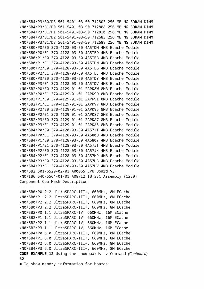
/N0/SB2 CPU 0 Temp. 0 54 Degrees C 7 sec OK/N0/SB2 CPU 0 1.8 VDC 0 1.72 Volts DC 7 sec OK/N0/SB2 CPU 1 Temp. 0 52 Degrees C 7 sec OK/N0/SB2 CPU 1 1.8 VDC 1 1.73 Volts DC 7 sec OK/N0/SB2 SBBC 1 Temp. 0 43 Degrees C 7 sec OK/N0/SB2 Board 1 Temp. 2 27 Degrees C 7 sec OK/N0/SB2 Board 1 Temp. 3 27 Degrees C 7 sec OK/N0/SB2 CPU 2 Temp. 0 51 Degrees C 7 sec OK/N0/SB2 CPU 2 1.8 VDC 0 1.71 Volts DC 7 sec OK/N0/SB2 CPU 3 Temp. 0 51 Degrees C 7 sec OK/N0/SB2 CPU 3 1.8 VDC 1 1.71 Volts DC 7 sec OK/N0/IB6 Board 0 1.5 VDC 0 1.51 Volts DC 7 sec OK/N0/IB6 Board 0 3.3 VDC 0 3.29 Volts DC 7 sec OK/N0/IB6 Board 0 5 VDC 0 4.95 Volts DC 7 sec OK/N0/IB6 Board 0 12 VDC 0 11.88 Volts DC 7 sec OK/N0/IB6 Board 0 Temp. 0 30 Degrees C 7 sec OK/N0/IB6 Board 0 Temp. 1 28 Degrees C 7 sec OKCODE EXAMPLE 26 Using the showenvironment Command (Continued)Alphabetical Command Reference 77For explanations of the showenvironment output headers see TABLE 11./N0/IB6 Board 0 3.3 VDC 1 3.30 Volts DC 7 sec OK/N0/IB6 Board 0 3.3 VDC 2 3.30 Volts DC 7 sec OK/N0/IB6 Board 0 1.8 VDC 0 1.81 Volts DC 7 sec OK/N0/IB6 Board 0 2.5 VDC 0 2.51 Volts DC 7 sec OK/N0/IB6 Fan 0 Cooling 0 High 3 sec OK/N0/IB6 Fan 1 Cooling 0 High 3 sec OK/N0/IB6 SDC 0 Temp. 0 63 Degrees C 8 sec OK/N0/IB6 AR 0 Temp. 0 73 Degrees C 8 sec OK/N0/IB6 DX 0 Temp. 0 68 Degrees C 8 sec OK/N0/IB6 DX 1 Temp. 0 72 Degrees C 8 sec OK/N0/IB6 SBBC 0 Temp. 0 49 Degrees C 8 sec OK/N0/IB6 IOASIC 0 Temp. 0 45 Degrees C 8 sec OK/N0/IB6 IOASIC 1 Temp. 1 51 Degrees C 8 sec OKTABLE 11 showenvironment Output Header DescriptionCode Example Header Value DescriptionSlot Slot IDDevice Device being monitored by the sensorSensor Component that measures the environmental data of thedeviceValue The value returned by the sensor ( data was acquiredAge seconds ago)Units Applicable unit for the sensor (for valid units, see theValue column)C CelsiusV VoltsAge Age of the reading being displayed (seconds)Status For values for Status see the Value column*** WARNING HIGH *** Value exceeded Max threshold* NOTICE High * Value between High-Warning and Max thresholds* NOTICE Low * Value below Min threshold*** WARNING LOW *** Value below Min thresholdOK Value is within limitsfailed Failed to receive sensor‘s valueCODE EXAMPLE 26 Using the showenvironment Command (Continued)78showerrorbuffer

Shows the contents of the error buffer.Syntaxshowerrorbuffer [–p [–n nnn]]showerrorbuffer –hOptions/ParametersThe following table lists all options or parameters and describes their use:DescriptionCaptures error message information detected by the system hardware error registersand stores them in an error buffer.All entry-level midrange systems have a dynamic error buffer that provides shorttermstorage of system error records. Once the system errors are recorded in themessage log buffer, system error records are cleared automatically from the dynamicerror buffer whenever more space in the buffer is required.Entry-level midrange systems with SC V2s have both dynamic and persistent errorbuffers. The persistent error buffer captures the system errors that occur and storesthe system error records until the error buffer is full. Once the persistent error bufferis full, any new system error records will overwrite the existing error records in thepersistent buffer, starting with the records at the beginning of the buffer.■ If your system is configured with SC V2s, which feature a persistent error buffer,you can use the –p and –n options to display messages stored in the persistenterror buffer. This information is maintained even after a system reboot occurs.■ Systems that have a small error buffer (where the SCs do not have enhancedmemory) cannot maintain persistent error messages—the contents of the errorbuffer are cleared when the SC reboots.–p Displays the error messages contained in the persistentsystem error buffer. This option is available only insystems configured with enhanced-memory systemcontrollers (SC V2s).–n nnn Displays a specified number (where nnn is an integer) oferror messages in chronological order.For example,–p –n 5 displays the last five errormessages in the persistent system error buffer.–h Displays help for the command.Alphabetical Command Reference 79However, if your domains are set to reboot automatically upon error, the outputfrom the showerrorbuffer command shows error messages that otherwisemight be lost when your domains are rebooted.You and your service provider can use this command to obtain information fortroubleshooting purposes.See AlsoNone.Examples■ To show a hardware error:■ To show persistent hardware error information maintained in the message bufferof a system configured with SC V2s.CODE EXAMPLE 27 showerrorbuffer Example Output for a Hardware Errorlom> showerrorbufferErrorData[0]Date: Fri Jan 30 10:23:32 EST 2004Device: /SSC1/sbbc0/systemepldRegister: FirstError[0x10] : 0x0200SB0 encountered the first errorErrorData[1]Date: Fri Jan 30 10:23:32 EST 2004Device: /SB0/bbcGroup0/repeaterepldRegister: FirstError[0x10]: 0x0002

sdc0 encountered the first errorErrorData[2]Date: Fri Jan 30 10:23:32 EST 2004Device: /SB0/sdc0ErrorID: 0x60171010Register: SafariPortError0[0x200] : 0x00000002ParSglErr [01:01] : 0x1 ParitySingle errorCODE EXAMPLE 28 showerrorbuffer Example Output – Persistent Error Informationlom> showerrorbuffer –p –n 2Date: Fri Jan 30 10:23:32 EST 2004Device: /SB0/bbcGroup0/repeaterepldRegister: FirstError[0x10]: 0x0002sdc0 encountered the first errorDate: Fri Jan 30 10:23:32 EST 2004Device: /SB0/sdc080ErrorID: 0x60171010Register: SafariPortError0[0x200] : 0x00000002ParSglErr [01:01] : 0x1 ParitySingle errorCODE EXAMPLE 28 showerrorbuffer Example Output – Persistent Error Information (Continued)Alphabetical Command Reference 81showescapeDisplays the current escape sequence.Syntaxshowescapeshowescape –hOptions/ParametersThe following table lists all options or parameters and describes their use:DescriptionThis command shows the current escape sequence.See AlsosetescapeExample–h Shows help for this command.lom> showescape#.82showeventreportingDisplays the settings applied to the LOM software event reporting and messages.Syntaxshoweventreportingshoweventreporting –hOptions/ParametersThe following table lists all options or parameters and describes their use:DescriptionShows the settings applied to the LOM software event reporting and messages.See AlsoseteventreportingExample–h Shows help for this command.lom> showeventreportingeventreporting is defaultreporting level is fatal, warning & information (3)Alphabetical Command Reference 83

showfaultDisplays the state of the system Fault LED.Syntaxshowfaultshowfault –hOptions/ParametersThe following table lists all options or parameters and describes their use:DescriptionShows the state of the system Fault LED.See AlsoshowalarmExample–h Displays help for this command.lom> showfaultfault is off84showhostnameDisplays the system hostname.Syntaxshowhostnameshowhostname –hOptions/ParametersThe following table lists all options or parameters and describes their use:DescriptionDisplay the hostname of the Solaris host.The hostname is only displayed if the Solaris Operating System is running,otherwise a – is displayedSee AlsoshowmodelExample–h Displays help for this command.lom> showhostnamehostnameAlphabetical Command Reference 85showlocatorDisplay the state of the system Locator LED.Syntaxshowlocatorshowlocator –hOptions/ParametersThe following table lists all options or parameters and describes their use:ExampleSee Alsosetlocator–h Displays help for this command.lom> showlocatorlocator is off86showlogsDisplays the system controller logged events stored in the system controller messagebuffer.Syntaxshowlogs [–p [–f filter][–n nnn]][–v]showlogs –hOptions/ParametersThe following table lists all options or parameters and describes their use:

DescriptionDisplays the log messages that are stored in the dynamic message buffer. Messagestorage in this dynamic buffer is temporary.■ Once the dynamic buffer is filled, the old messages that are logged to the consolesare overwritten by the new messages (these are messages from the systemcontroller, not the Solaris Operating System).■ The dynamic buffer is cleared when you reboot the system controller or when aloss in power occurs.–p Displays the error messages contained in the persistenterror buffer. This option is available only in systemsconfigured with enhanced-memory system controllers (SCV2s).–n nnn Displays a specified number (where nnn is an integer) oferror messages in chronological order.For example,–p –n 5 displays the last five errormessages in the persistent error buffer.–f filter Indicates a certain type of message information is to bedisplayed, where filter is one of the following:• alert – alert messages• critical – critical messages• emergency – emergency messages• error – error messages• fault – fault messages• warning – warning messages–h Displays help for the command.Alphabetical Command Reference 87In systems with SC V2s, messages in the dynamic buffer that have the followingseverity levels are retained in persistent storage, and will survive a system reboot orloss in power: .alert, .error, .emerg, .warning, and .critical. If thepersistent storage buffer becomes full, any new messages will wrap to the beginningof the buffer and the existing messages at the beginning of the buffer will beoverwritten by the newest messages.If the loghost has been configured, then the messages will also be logged to theloghost for storage.See Also■ history■ resetscExample■ To display the output of the showlogs command, run at the console afterrebooting the system:CODE EXAMPLE 29 Example Output of the showlogs Command Run After Rebooting the Systemlom> showlogsFri Jan 30 10:07:19 commando lom: [ID 512236 local0.notice] Boot: ScApp 5.17.0,RTOS 38Fri Jan 30 10:07:21 commando lom: [ID 427980 local0.notice] SBBC ResetReason(s): Peer Reset, Watchdog ResetFri Jan 30 10:07:28 commando lom: [ID 390645 local0.notice] Caching IDinformationFri Jan 30 10:07:29 commando lom: [ID 667165 local0.notice] Clock Source: 12430-synthesizerFri Jan 30 10:07:34 commando lom: [ID 641509 local0.notice] /N0/PS0: Status is OKFri Jan 30 10:07:35 commando lom: [ID 251798 local0.notice] /N0/PS1: Status is OKFri Jan 30 10:07:36 commando lom: [ID 762068 local0.notice] /N0/PS2: Status is OKFri Jan 30 10:07:36 commando lom: [ID 372357 local0.notice] /N0/PS3: Status is OKFri Jan 30 10:07:37 commando lom: [ID 515227 local0.notice] Chassis is in single

partition mode.Fri Jan 30 10:08:24 commando lom: [ID 428967 local0.notice] Partially poweredon board CPU Board V3 at /N0/SB2 powered offFri Jan 30 10:08:39 commando lom: [ID 939453 local0.notice] Clear/N0/SB4/P1/B1/D2 invalid segmentFri Jan 30 10:09:10 commando lom: [ID 965595 local0.warning] Keyswitch wasinterrupted on domain A. Recovering....Fri Jan 30 10:09:29 commando lom: [ID 629580 local0.notice] Domain A is now inkeyswitch "off" positionFri Jan 30 10:09:30 commando lom: [ID 596773 local0.notice] Starting telnetserver ...88■ To display persistent log output for a system with SC V2s, run at the console:CODE EXAMPLE 30 Example showlogs Persistent Log Outputlom>showlogs –pFri Jan 30 10:09:10 commando lom: [ID 965595 local0.warning] Keyswitch wasinterrupted on domain A. Recovering....Fri Jan 30 10:13:45 commando lom: [ID 991471 local0.warning] Agent {/N0/SB0/P0}is disabled.Fri Jan 30 10:13:45 commando lom: [ID 388680 local0.warning] Agent {/N0/SB0/P1}is disabled.Fri Jan 30 10:14:04 commando lom: [ID 685870 local0.warning] Agent {/N0/SB0/P2}is disabled.Fri Jan 30 10:14:04 commando lom: [ID 983060 local0.warning] Agent {/N0/SB0/P3}is disabled.Fri Jan 30 10:14:27 commando lom: [ID 392085 local0.warning] Agent{/N0/SB2/P0/C0} is disabled.Fri Jan 30 10:14:27 commando lom: [ID 689275 local0.warning] Agent{/N0/SB2/P0/C1} is disabled.Fri Jan 30 10:14:28 commando lom: [ID 403192 local0.warning] Port {/N0/SB2/P0}is disabled.Fri Jan 30 10:14:28 commando lom: [ID 392149 local0.warning] Agent{/N0/SB2/P1/C0} is disabled.Fri Jan 30 10:14:28 commando lom: [ID 689339 local0.warning] Agent{/N0/SB2/P1/C1} is disabled.Fri Jan 30 10:14:28 commando lom: [ID 700382 local0.warning] Port {/N0/SB2/P1}is disabled.Fri Jan 30 10:14:44 commando lom: [ID 392213 local0.warning] Agent{/N0/SB2/P2/C0} is disabled.Fri Jan 30 10:14:44 commando lom: [ID 689403 local0.warning] Agent{/N0/SB2/P2/C1} is disabled.Fri Jan 30 10:14:45 commando lom: [ID 997572 local0.warning] Port {/N0/SB2/P2}is disabled.Fri Jan 30 10:14:45 commando lom: [ID 392277 local0.warning] Agent{/N0/SB2/P3/C0} is disabled.Fri Jan 30 10:14:45 commando lom: [ID 689467 local0.warning] Agent{/N0/SB2/P3/C1} is disabled.Fri Jan 30 10:14:45 commando lom: [ID 394781 local0.warning] Port {/N0/SB2/P3}is disabled.Fri Jan 30 10:15:15 commando lom: [ID 152595 local0.warning] Agent {/N0/SB4/P0}is CHS disabled.Fri Jan 30 10:15:15 commando lom: [ID 152597 local0.warning] Agent {/N0/SB4/P1}is CHS disabled.Fri Jan 30 10:15:41 commando lom: [ID 152599 local0.warning] Agent {/N0/SB4/P2}is CHS disabled.Fri Jan 30 10:15:41 commando lom: [ID 152601 local0.warning] Agent {/N0/SB4/P3}

is CHS disabled.Alphabetical Command Reference 89■ To display persistent log output in which only critical messages are displayed:■ To display the last five messages in the buffer of persistent log output:Fri Jan 30 10:18:30 commando lom: [ID 947844 local0.warning] Excluded unusable,failed or disabled board: /N0/SB0Fri Jan 30 10:18:31 commando lom: [ID 947848 local0.warning] Excluded unusable,failed or disabled board: /N0/SB4Fri Jan 30 10:18:31 commando lom: [ID 947846 local0.warning] Excluded unusable,failed or disabled board: /N0/SB2Fri Jan 30 10:18:31 commando lom: [ID 304509 local0.error] No usable Cpu boardin domain.CODE EXAMPLE 31 Example showlogs Persistent Log Output, Critical messages Onlylom>showlogs –p –f criticalMon Jan 26 10:06:07 commando lom: [ID 920266 local0.crit] ErrorMonitor: DomainA has a SYSTEM ERRORMon Jan 26 10:06:07 commando lom: [ID 920266 local0.crit] ErrorMonitor: DomainA has a SYSTEM ERRORMon Jan 26 10:06:11 commando lom: [ID 764738 local0.crit] A fatal condition isdetected on Domain A. Initiating automatic restoration for this domain.Mon Jan 26 10:06:11 commando lom: [ID 764738 local0.crit] A fatal condition isdetected on Domain A. Initiating automatic restoration for this domain.Fri Jan 30 10:02:39 commando lom: [ID 920266 local0.crit] ErrorMonitor: DomainA has a SYSTEM ERRORFri Jan 30 10:02:39 commando lom: [ID 920266 local0.crit] ErrorMonitor: DomainA has a SYSTEM ERRORFri Jan 30 10:02:49 commando lom: [ID 764738 local0.crit] A fatal condition isdetected on Domain A. Initiating automatic restoration for this domain.Fri Jan 30 10:02:50 commando lom: [ID 764738 local0.crit] A fatal condition isdetected on Domain A. Initiating automatic restoration for this domain.Fri Jan 30 10:22:55 commando lom: [ID 920266 local0.crit] ErrorMonitor: DomainA has a SYSTEM ERRORFri Jan 30 10:22:55 commando lom: [ID 920266 local0.crit] ErrorMonitor: DomainA has a SYSTEM ERRORFri Jan 30 10:23:06 commando lom: [ID 764738 local0.crit] A fatal condition isdetected on Domain A. Initiating automatic restoration for this domain.Fri Jan 30 10:23:06 commando lom: [ID 764738 local0.crit] A fatal condition isdetected on Domain A. Initiating automatic restoration for this domain.CODE EXAMPLE 32 Example showlogs Persistent Log Output, Specific Number of Messages Displayedlom>showlogs –p –n 5Fri Jan 30 10:26:20 commando lom: [ID 392277 local0.warning] Agent{/N0/SB2/P3/C0} is disabled.CODE EXAMPLE 30 Example showlogs Persistent Log Output (Continued)90Fri Jan 30 10:26:20 commando lom: [ID 689467 local0.warning] Agent{/N0/SB2/P3/C1} is disabled.Fri Jan 30 10:26:20 commando lom: [ID 394781 local0.warning] Port {/N0/SB2/P3}is disabled.Fri Jan 30 10:26:23 commando lom: [ID 947846 local0.warning] Excluded unusable,failed or disabled board: /N0/SB2Fri Jan 30 10:26:28 commando lom: [ID 304509 local0.error] No usable Cpu boardin domain.lom>CODE EXAMPLE 32 Example showlogs Persistent Log Output, Specific Number of

Messages DisplayedAlphabetical Command Reference 91showmodelDisplays the platform model.Syntaxshowmodelshowmodel –hOptions/ParametersThe following table lists all options or parameters and describes their use:DescriptionDisplays the name of the system platform model.See AlsoshowhostnameExample–h Displays help for this command.lom>showmodelmodel: Sun Fire V128092shownetworkDisplays system controller (LOM) network settings and MAC addresses.Syntaxshownetwork [–v]shownetwork –hOptions/ParametersThe following table lists all options or parameters and describes their use:DescriptionShow System Controller (LOM) network settings and MAC addresses.Example–v Verbose mode. Displays the system Ethernet (MAC)addresses.–h Displays help for this command.lom> shownetworkNetwork-------The system controller is configured to be on a network.Network settings: staticHostname: commando-scIP Address: 129.xxx.xxx.xxxGateway: 129.xxx.xxx.xxxDNS Domain: noone.somewhere.comPrimary DNS Server: 129.xxx.xxx.xxxSecondary DNS Server: 129.xxx.xxx.xxxConnection type: telnetAlphabetical Command Reference 93See Alsosetupnetworklom> shownetwork –vNetwork-------The system controller is configured to be on a network.Network settings: staticHostname: commando-scIP Address: 129.xxx.xxx.xxxNetmask: 255.255.255.0Gateway: 129.xxx.xxx.xxxDNS Domain: noone.somewhere.com

Primary DNS Server: 129.xxx.xxx.xxxSecondary DNS Server: 129.xxx.xxx.xxxConnection type: telnetMAC Address HostID------------------------------- --------Host net0 00:03:ba:19:8b:89 83198b89Host net1 00:03:ba:19:8b:8a 83198b8aSC net 00:03:ba:19:8b:92 83198b9294showresetstateDisplays the CPU registers after an abnormal Solaris reset.Syntaxshowresetstate [–w|–s|–v] [–f URL]showresetstate –hOptions/ParametersThe following table lists all options or parameters and describes their use:DescriptionShows the CPU registers after an abnormal Solaris reset, for example, as a result of aSolaris watchdog timeout.–w Shows windows.–s Shows secondary save registers.–v Shows all registers.–f Specify a URL for the outputURL The file to receive the output.The supported protocol is FTP:ftp://[userid:password@]hostname/path–h Displays help for this command.Alphabetical Command Reference 95showscDisplays version and uptime information about the system controller.Syntaxshowsc [–v]showsc –hOptions/ParametersThe following table lists all options or parameters and describes their use:DescriptionDisplays version, uptime, as well as Solaris status and COD information about thesystem controller.Example–v Verbose.–h Displays help for this command.CODE EXAMPLE 33 Using the showsc Commandlom> showscSC: SSC1System ControllerClock failover disabled.SC date: Thu Jul 01 11:19:03 EDT 2004SC uptime: 1 hour 26 minutes 52 secondsScApp version: 5.18.0 Build_09RTOS version: 40Solaris Host Status: Powered OffChassis HostID: 83198b89PROC RTUs installed: 0PROC Headroom Quantity: 0lom>96

shutdownShuts down the Solaris software and enters standby mode.Syntaxshutdownshutdown –hOptions/ParametersThe following table lists all options or parameters and describes their use:DescriptionIf Solaris is running, the system is cleanly halted and then powered off to standbymode. If Solaris is not running then the system is powered off to standby mode.This should be used in preference to the poweroff command.See Alsopoweron, poweroffExample–h Displays help for this command.lom>shutdownShutting down Solaris ...lom>lom>consoleThe system is down.syncing file systems... donePowering off ...lom>Powering boards off ...Alphabetical Command Reference 97ssh-keygenGenerates Secure Shell (SSH) host keys or displays the SSH host key fingerprint.Syntaxssh-keygen [–l] [–t <rsa|dsa>]ssh-keygen [–r]ssh-keygen [–h]Options/ParametersThe following table lists all options or parameters and describes their use:DescriptionGenerates SSH host keys or displays the host key fingerprint on the SC.When the SSH server has been enabled on the SC, the firmware checks whether anSSH host key exists. If not, the firmware generates (automatically) a pair of RSAprivate/public host keys. If you want DSA host keys on the SC, you must invokessh-keygen manually with the –t switch.Once generated, new host keys take effect (are loaded into memory) after:■ The SSH server is (re-) enabled■ The system is rebooted and the SSH server is enabled■ The restartssh command is invoked while the SSH server is enabledIt is good security practice for well-managed machines to get new host keysperiodically. If you suspect that the key has been compromised, you can run thessh-keygen command to regenerate system host keys. Host keys, once generated,can only be replaced and not deleted. For newly generated host keys to take effect,the SSH server must be restarted, either by running the restartssh command orwith a reboot.Since host keys are large, 1 Kbyte in size, it is difficult to verify an entire host key.ssh-keygen can be used to display a host key fingerprint, which is the output ofthe md5 message-digest algorithm presented as a sequence of 16 octets printed ashexadecimal with lowercase letters and separated by colons. See CODE EXAMPLE 34.–l Shows the host key fingerprint. Default is RSA.–t Specifies the type of host key. Default is RSA.–r Regenerates host key.

-h Displays help for this command.98Since host keys are stored on the SC, they get backed up with dumpconfig and canbe restored by restoreconfig (By default, the dumpconfig command saves keysin encrypted format). When an SC failover occurs, the keys get copied to theredundant SC. In other words, the main SC and the redundant SC share the same setof SSH keys.You can regenerate the host keys at any time by running ssh-keygen. If the hostkey already exists, you must specify the –r switch.See AlsorestartsshExampleCODE EXAMPLE 34 ssh-keygen Command Examplelom> ssh-keygen -r -t rsaUse ’restartssh’ to restart the SSH server with the new host key.lom>ssh-keygen -l7d:0f:e7:50:b3:dc:68:75:89:cc:d5:4b:0d:35:b0:e7 (RSA host key)Alphabetical Command Reference 99testboardTests the specified CPU/Memory board.Syntaxtestboard [–f] board-nametestboard –hOptions/ParametersThe following table lists all options or parameters and describes their use:DescriptionRuns POST on the CPU/Memory board specified on the command line. The boardmust not be in use by Solaris at the time (that is, its status as displayed byshowboards must not be Active). To display the board status use the showboardscommand.Example■ To test CPU/Memory board, sb0, type:–f Force testing of an already–tested board.board-name The board to be tested, and must be one of sb0, sb2 orsb4.–h Displays help for this command.lom> testboard sb0100101GlossaryCapacity on Demand(COD) Capacity on Demand (COD) is an option that provides additional processingresources (CPUs) when you need them. These additional CPUs are providedon COD CPU/Memory boards that are installed in Sun Fire entry-levelmidrange systems. You can access the COD CPUs after you purchase the CODright-to-use (RTU) licenses for them.environmentalmonitoring All systems have a large number of sensors that monitor temperature, voltage,and current. The system controller polls devices in a timely manner and makesthe environmental data available. The system controller shuts down variouscomponents to prevent damage.FRU Field-Replaceable Unit. A discrete part of the system, such as a power supply,a CPU/Memory board or a fan.LOM Lights Out Management.LOM prompt The LOM prompt provides configuration control, environmental status,

theability to power on and off the system, the ability to change the SystemController password and access to other system controller functions.If POST, the Solaris Operating System, or the OpenBoot PROM is not runningand only the system controller software is running, you can access the LOMprompt, which is lom>.It also provides a location for console messages to be displayed.POST Power-on self-test. This program that takes probes and tests the components ofuninitialized system hardware, configures the components into a coherentinitialized system, and hands it off to the OpenBoot PROM.RTU license Right-to-use license.ScApp The software application that runs on the system controller and whichprovides a command-line interface for you to modify the system settings.102SEPROM Serial Eraseable Programmable Read-Only Memory.System Controller The system controller is an embedded system resident on the IB_SSC assemblythat connects to the system baseplane. The system controller is responsible forproviding the Lights Out Management (LOM) functions which include poweron sequencing, sequencing module power-on self-tests (POST), environmentalmonitoring, fault indication and alarms.virtual time of day(TOD) The TOD/NVRAM chip is located on the system controller board. The systemcontroller multiplexes the physical TOD chip to provide TOD services.103IndexAaddcodlicense command, 6alarmssetting, 33show setting, 52Bboard status, showing, 54boards, testing, 99boot, configure, 7bootmode command, 7break character, 9break command, 9break command, disabling, 48CCOD (Capacity on Demand)resource use, 67RTU licenses, 6, 11, 65command history, 20command summary, 1component health status (CHS), 42component location status, 42component, showing, 69configure Solaris boot, 7console command, 10console connection, 10console port commands, 1CPU/Memory board, testing, 99Ddate

displaying, 72setting, 34deletecodlicense command, 11displayingversion and uptime information, 95Eenvironment, show measurements, 73escape characters, showing, 81event log, show, 86event reporting, show status, 82Ffault LED, show status, 83flash PROMs, updating, 16flashupdate command, 16Hhelp command, 18history command, 20hostname, showing, 84Iinventory command, 21Llogout command, 22104Nnetwork, setting parameters, 46network, show settings, 92OOn/Standby switch, disabling, 48Ppassword command, 23password, setting, 23persistent logginglog messages, 87platform, show model, 91powering on, 26poweroff command, 24poweron command, 26Rreset command, 28reset command, disabling, 48reset state, show, 94reseting the system controller, 30resetsc command, 30resetting, system, 28restartssh command, 32RTU (right to use) licenses, 6, 11, 65SSCPOST, setting level, 48SEPROM contents, show, 21setalarm command, 33setdate command, 34setlocator command, 41setls command, 42setting date, 34setting time, 34setupnetwork command, 46

setupsc command, 48showalarm command, 52showboards command, 54showcodlicense command, 65showcodusage command, 67showcomponent command, 69showdate command, 72showenvironment command, 73showerrorbuffer command, 78showescape command, 81showeventreporting command, 82showfault command, 83showhostname command, 84showlogs command, 86showmodel command, 91shownetwork command, 92showresetstate command, 94showsc command, 95shutdown command, 96SSH (Secure Shell) protocolhost keys, 97restarting the SSH server, 32ssh-keygen command, 97system controllerconfiguring, 48resetting, 30system controller software command summary, 1system LED, setting, 41system, resetting, 28Ttestboard command, 99testing, CPU/Memory board, 99timedisplaying, 72setting, 34Uupdating the flash PROMs, 16uptime and version information, displaying, 95Vversion and uptime information, displaying, 95Wwatchdog, disabling, 48