v nokia 12 gsm module - hmangas.com 12... · this document provides an overview of software...
TRANSCRIPT

Cop
yrig
ht ©
200
4-20
05 N
okia
. All
right
s re
serv
ed.
Iss
ue 1
.1
9231
710
NOKIA 12 GSM MODULE SOFTWARE DEVELOPER’S GUIDE
Contents
ACRONYMS AND TERMS ......................................................................................................1 DEFINITIONS...........................................................................................................................3 1 ABOUT THIS DOCUMENT ................................................................................................4 2 SYSTEM ARCHITECTURE................................................................................................5
2.1 INTRODUCTION ..........................................................................................................5 2.2 LOCAL CONNECTIVITY ..............................................................................................6 2.3 WIRELESS CONNECTIVITY .......................................................................................7
2.3.1 TCP/UDP sockets .................................................................................................8 2.3.2 SMS.......................................................................................................................9 2.3.3 AT commands .......................................................................................................9
3 DEVELOPING SOFTWARE FOR THE NOKIA 12 GSM MODULE..................................10 3.1 INTRODUCTION ........................................................................................................10 3.2 JAVATM APPLICATIONS IN THE NOKIA 12 GSM MODULE.....................................10
3.2.1 Java Application Development Environment.......................................................10 3.2.2 The Nokia 12 GSM module Java APIs................................................................12
3.3 APPLICATIONS IN AN APPLICATION MODULE......................................................13 3.3.1 M2M System Protocol 2 socket interface ............................................................13 3.3.2 AT commands .....................................................................................................14
3.4 NOKIA 12 GSM MODULE SERVICES.......................................................................15 4 COMMUNICATION INFRASTRUCTURE.........................................................................17
4.1 INTRODUCTION ........................................................................................................17 4.2 IP COMMUNICATION IN WIRELESS NETWORKS ..................................................17
4.2.1 CSD connection using a mobile handset ............................................................18 4.2.2 CSD connection using a modem pool .................................................................18 4.2.3 GPRS connection using GPRS access points ....................................................20
4.3 WIRELESS BEARER CONFIGURATION ..................................................................22 4.3.1 Configuring a CSD connection between the Nokia 12 GSM module and a mobile
handset................................................................................................................22 4.3.2 Configuring a socket connection using CSD .......................................................25 4.3.3 Configuring a socket connection using GPRS ....................................................26 4.3.4 Configuring an HTTP connection using GPRS and CSD....................................27

5 M2M APPLICATION DEVELOPMENT AND DEPLOYMENT EXAMPLE.........................30 5.1 INTRODUCTION ........................................................................................................30 5.2 APPLICATION DEVELOPMENT AND DEPLOYMENT CHARACTERISTICS...........30
5.2.1 Example scenario................................................................................................30 5.2.2 Overall process ...................................................................................................31 5.2.3 Product development ..........................................................................................33 5.2.4 Production ...........................................................................................................33 5.2.5 On-site deployment .............................................................................................34 5.2.6 Operational phase ...............................................................................................35
6 NOKIA 12 GSM MODULE REMOTE MANAGEMENT.....................................................37 6.1 INITIAL REMOTE CONFIGURATION ........................................................................37
6.1.1 Basic functionality................................................................................................37 6.1.2 Nokia 12 GSM module settings...........................................................................39
6.1.2.1 Example configurations...................................................................................39 6.1.2.2 Configuration parameters in characteristics....................................................44
6.1.3 Structure of a smart message .............................................................................48
6.1.3.1 Wireless Session Protocol header ..................................................................48 6.1.3.2 Message body.................................................................................................48 6.1.3.3 Coding a characteristic to a smart message ...................................................49
6.1.4 Example message coded as a smart message...................................................50 6.1.5 Sending a smart message in a short message ...................................................55
6.1.5.1 The Protocol Data Unit of the short message .................................................55 6.1.5.2 Wireless Application Protocol header .............................................................55 6.1.5.3 Smart message ...............................................................................................56 6.1.5.4 AT commands .................................................................................................56
6.2 SERVER-INITIATED GPRS CONTEXT ACTIVATION ..............................................57 6.2.1 Introduction..........................................................................................................57 6.2.2 SMS bearer configuration for the Nokia 12 GSM module ...................................59
6.2.2.1 Configuring an SMS connection for the Wake-Up Service .............................59 6.2.2.2 Wireless Transaction Protocol port .................................................................60 6.2.2.3 Phone number.................................................................................................60 6.2.2.4 Server (gateway) information ..........................................................................60
6.2.3 Structure of the wake-up short message.............................................................60

6.2.3.1 Wireless Application Protocol header .............................................................60 6.2.3.2 Message data..................................................................................................61
6.2.4 In-built Wake-Up Service.....................................................................................61
6.2.4.1 Bearer configuration........................................................................................62 6.2.4.2 Wake-up sequences .......................................................................................62 6.2.4.3 The structure of the GIOP message ...............................................................64
6.2.5 Alternative Wake-Up Service ..............................................................................66
6.2.5.1 Structure of the message ................................................................................66 6.2.5.2 Wake-up sequence .........................................................................................66
6.2.6 Sending the wake-up short message ..................................................................68 6.3 NOKIA 12 GSM MODULE REMOTE CONFIGURATION ..........................................68 6.4 JAVA IMLET REMOTE MANAGEMENT ....................................................................68
6.4.1 Introduction..........................................................................................................69 6.4.2 IMlet Suite Manager service................................................................................69
6.4.2.1 IMlet Suite Manager interface definition..........................................................69 6.4.2.2 IMlet Suite Manager CORBA servant .............................................................72 6.4.2.3 IMlet Suite Manager interface methods ..........................................................73
6.4.3 Downloading IMlet Suites into the Nokia 12 GSM module..................................75 6.4.4 Managing IMlet Suites in the Nokia 12 GSM module..........................................78
6.4.4.1 Managing IMlet Suites.....................................................................................78 6.4.4.2 Managing IMlet applications............................................................................79
6.4.5 Runtime events ...................................................................................................79 6.4.6 Example application ............................................................................................80

Legal Notice
Copyright © 2004-2005 Nokia. All rights reserved.
Reproduction, transfer, distribution or storage of part or all of the contents in this document in any form without the prior written permission of Nokia is prohibited.
Nokia and Nokia Connecting People are registered trademarks of Nokia Corporation. Java and all Java-based marks are trademarks or registered trademarks of Sun Microsystems, Inc. Other product and company names mentioned herein may be trademarks or trade names of their respective owners.
Nokia operates a policy of continuous development. Nokia reserves the right to make changes and improvements to any of the products described in this document without prior notice.
Under no circumstances shall Nokia be responsible for any loss of data or income or any special, incidental, consequential or indirect damages howsoever caused.
The contents of this document are provided "as is". Except as required by applicable law, no warranties of any kind, either express or implied, including, but not limited to, the implied warranties of merchantability and fitness for a particular purpose, are made in relation to the accuracy, reliability or contents of this document. Nokia reserves the right to revise this document or withdraw it at any time without prior notice.

ACRONYMS AND TERMS
Acronym/term Description
AM Application Module
API Application Programming Interface
APN Access Point Name
AT ATtention (command language)
BSD Berkeley Standard Distribution
CHAP Challenge Handshake Authentication Protocol
CLDC Connected Limited Device Configuration
CORBA Common Object Request Broker Architecture
CSD Circuit Switched Data
EDGE Enhanced Data Rates for Global Evolution
EGPRS Enhanced General Packet Radio Service
EGSM Extended GSM
ET Embedded Terminal (here Nokia 12 GSM module)
GIOP General Inter-ORB Protocol
GPRS General Packet Radio Service
GSM Global System for Mobile Communications
GPS Global Positioning System
HLA Home Location Agent
HSCSD High Speed Circuit Switched Data
HTTP Hypertext Transfer Protocol
IMEI International Mobile Equipment Identity
IMlet Java™ application that runs according to the Information Module Profile (JSR-195)
IMP Information Module Profile
I/O Input/Output
IIOP Internet Inter-ORB Protocol
IP Internet Protocol
ISDN Integrated Services Digital Network
JAR Java Archive
J2ME™ Java 2 Micro Edition
J2RE™ Java 2 Runtime Environment
1/83
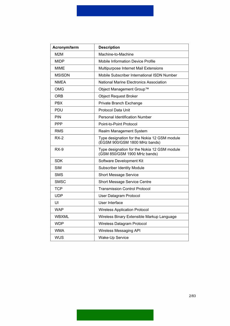
Acronym/term Description
M2M Machine-to-Machine
MIDP Mobile Information Device Profile
MIME Multipurpose Internet Mail Extensions
MSISDN Mobile Subscriber International ISDN Number
NMEA National Marine Electronics Association
OMG Object Management Group™
ORB Object Request Broker
PBX Private Branch Exchange
PDU Protocol Data Unit
PIN Personal Identification Number
PPP Point-to-Point Protocol
RMS Realm Management System
RX-2 Type designation for the Nokia 12 GSM module (EGSM 900/GSM 1800 MHz bands)
RX-9 Type designation for the Nokia 12 GSM module (GSM 850/GSM 1900 MHz bands)
SDK Software Development Kit
SIM Subscriber Identity Module
SMS Short Message Service
SMSC Short Message Service Centre
TCP Transmission Control Protocol
UDP User Datagram Protocol
UI User Interface
WAP Wireless Application Protocol
WBXML Wireless Binary Extensible Markup Language
WDP Wireless Datagram Protocol
WMA Wireless Messaging API
WUS Wake-Up Service
2/83

DEFINITIONS
Term Definition
Application Module A runtime environment for the customer remote application that is connected to the Nokia 12 GSM module via local connectivity. Typically it is a part of the remote device (such as a vending machine) or a separate bridging element.
Customer remote application An application in the remote end of the M2M solution. It can be executed in the Application Module (AM), Java™ 2 Runtime Environment (J2RE™) of the Nokia 12 GSM module, or in both.
Customer server application Can vary from a standalone application to a larger enterprise solution in the server end of the M2M solution. The customer server application is typically located in the customer intranet.
Remote device A remote element (such as a vending machine) that is a part of the M2M solution.
3/83

1 ABOUT THIS DOCUMENT
This document provides an overview of software development with the Nokia 12 GSM module (hereafter Nokia 12 module). The document describes the basic software development principles from the software developer’s point of view. That is, software developers working with the Nokia 12 module can use this guide to get a system level view of software development before starting the actual programming tasks.
For more detailed programming instructions, refer to the following documents:
• Nokia 12 GSM Module JavaTM IMlet Programming Guide This document introduces the reader to Java application programming for Nokia 12 modules. It includes instructions on how to program, build, install, run, and debug Java applications using the Nokia 12 module, and presents the required software tools for application development.
The document also introduces the Java Application Programming Interfaces (API) supported by the Nokia 12 module.
• Nokia M2M System Protocol 2 Socket Interface User Manual This document describes how an Application Module (AM) can establish a serial connection to the TCP/IP stack located in the Nokia 12 module.
• Nokia 12 GSM Module Hardware Integration Manual This document provides instructions for the Nokia 12 module hardware integration. The document is intended to help the system integrators to integrate the Nokia 12 module into a remote end hardware application and to gain the necessary type approvals.
• Nokia 12 GSM Module Interface Definition Reference Guide and Nokia 12 GSM Module Properties Reference Guide
The Nokia 12 GSM Module Interface Definition Reference Guide gives detailed information about the Nokia 12 module services that are available for the application developer. The Nokia 12 GSM Module Properties Reference Guide describes the Nokia 12 module parameters, events, and counters that are used via the functions described in the Nokia 12 GSM Module Interface Definition Reference Guide.
The actual interface definitions, in which the services, parameters, events, and counters of the Nokia 12 module are formally defined, can be found in the Nokia 12 Software Development Kit (SDK).
For more detailed information about the Nokia 12 module and Nokia 12 SDK, and for extensive application development documentation, see the Forum Nokia pages at http://www.forum.nokia.com/m2m or www.americas.forum.nokia.com/m2m.
4/83

2 SYSTEM ARCHITECTURE
2.1 INTRODUCTION “How do I build M2M connectivity between the remote system and our intranet? This is typically the dilemma that has to be solved when planning M2M system architecture.
As a solution to the dilemma, Nokia offers the Nokia 12 module that provides both wireless connectivity between the customer’s remote device(s) and intranet, and local connectivity for managing the components of the remote device(s).
There are two versions of the Nokia 12 module:
• RX-2 dual-band GSM device supporting EDGE, GPRS, HSCSD, CSD, and SMS in EGSM 900/GSM 1800 MHz bands.
Note: An enhanced version of the RX-2, Nokia 12i module, includes GPRS class 10, EDGE class 6, AMR voice codec, and RoHS-free hardware.
• RX-9 dual band GSM device supporting EDGE, GPRS, CSD, SMS in GSM 850/GSM 1900 MHz bands.
Figure 1 illustrates the role of the Nokia 12 module in a typical M2M system architecture.
Remote device(s)
GSMnetwork
Nokia 12GSM
module
Intranet
Local connectivity
Wireless connectivity
Figure 1. The Nokia 12 GSM module in a typical M2M system architecture The Nokia 12 module provides a wide variety of connection types for local as well as wireless connectivity. For more information on the connectivity solutions available via the Nokia 12 module, see Chapters 2.2 and 2.3.
5/83

2.2 LOCAL CONNECTIVITY This chapter provides an overview of the connection types that are available for connecting the Nokia 12 module to a remote device.
Note: The Nokia 12 module does not have separate physical interfaces for each connection type. The way that data is routed via the physical interfaces depends on the connection type and the remote device(s) that are used.
Local connectivity between the Nokia 12 module and a remote device can be established using:
• Transmission Control Protocol (TCP) sockets
• User Datagram Protocol (UDP) sockets
• Asynchronous serial connection
• Control connection
• AT commands
• I/O control connection
• Global Positioning System (GPS) connection (for an external GPS device) Figure 2 illustrates the local connectivity options that are available via the Nokia 12 module and its Java environment.
Nokia 12 GSM module
Remotedevice
I/O
TCP/UDP socket
AT
Wirelessconnectivity
Serial (asynchronous)
GPS
Control (reset...)
AMJava
NMEA
Figure 2. The local connectivity options available via the Nokia 12 GSM module
6/83

Local connectivity options for the Nokia 12 GSM module TCP/UDP sockets make it possible to route IP traffic between a remote device and the Nokia 12 module via a standard socket interface. For more information on using TCP/UDP sockets and the socket interface, see the Nokia M2M System Protocol 2 Socket Interface User Manual and the Nokia 12 GSM Module JavaTM IMlet Programming Guide.
The asynchronous serial connection enables communication between the IMlet and a remote device. For more information on how to use the asynchronous serial connection, see the Nokia 12 GSM Module JavaTM IMlet Programming Guide.
The control connection between a remote device and the Nokia 12 module makes it possible, for example, to a reset remote device via the Nokia 12 module and vice versa. For more information on the control connection, see the Nokia 12 GSM Module Hardware Integration Manual.
The modem functionality of the Nokia 12 module enables the use of AT commands. AT commands can be used, for example, for faxing. They can also be used to test software in the application development phase. For more information, see the Nokia 12 GSM Module AT Command Guide.
The Nokia 12 module also has several analog/digital input pins and digital output pins that can be used to control simple I/O applications. The I/O pins of the Nokia 12 module can be controlled from the customer server application or IMlet. It is also possible to control the I/O pins of the Nokia 12 module from a mobile handset using short messages. For more information on controlling the I/O pins from a mobile handset, see the Nokia 12 GSM Module User Control Mode Guide.
In addition it is possible to connect the Nokia 12 module to an external GPS device that supports the NMEA standard. The Nokia 12 module includes an NMEA parser that is able to parse the location data (such as location coordinates, altitude, date and time) from the output that it receives from the GPS device. The location data gathered in the Nokia 12 module can be distributed to a Java application, mobile handset as well as to the customer remote and server applications by using wireless bearers. For more information on using GPS with the Nokia 12 module, see the Nokia 12 GSM Module Interface Definition Reference Guide. For an example on using GPS via a Java application, see the Nokia 12 GSM Module JavaTM IMlet Programming Guide.
2.3 WIRELESS CONNECTIVITY The Nokia 12 module provides wireless connectivity over GSM network using (E)GPRS, (HS)CSD, and SMS bearers. How the wireless connectivity of the Nokia 12 module is used, depends on the application.
7/83
2.3.1 TCP/UDP sockets The Nokia 12 module has integrated TCP and UDP stacks that can be used by customer remote applications. The bearers available for TCP and UDP sockets are (HS)CSD and (E)GPRS. Java applications can use TCP and UDP protocols through the Java Socket API, and AMs can use them through the M2M System Protocol 2 socket interface.
The in-built protocol implementations of the Nokia 12 module cover Point-to-Point Protocol (PPP) and Challenge Authentication Protocol (CHAP). The configuration values needed by wireless connections, for example GPRS access-point name, are also built-in to the Nokia 12 module. Application developers can change these configuration values by using the Nokia 12 Configurator, and Java applications can change the configuration values via the programming interfaces.
Java applications can use TCP and UDP sockets via the Java Socket API. The Nokia 12 module provides in-built, automatic GPRS and CSD link handling, which makes it possible for application developers to use the Java Socket API without learning the details of the network connection architecture and authentication. For more information, see the Nokia 12 GSM Module JavaTM IMlet Programming Guide.
The Nokia M2M System Protocol 2 socket interface allows application developer’s to build an AM, which does not have PPP/CHAP/IP/UDP/TCP protocol stacks. All that is needed to allow an AM to use Berkeley Standard Distribution (BSD) type sockets are the Nokia M2M System Protocol 2 and M2M System Protocol socket interface. Because the M2M System Protocol uses the in-built stacks and configurations of the Nokia 12 module, there is no need to implement permanent configuration storage for wireless link configuration values, such as user names and passwords, into AMs. This reduces the number of software components required in AM implementation. For more information, see the Nokia M2M System Protocol 2 Socket Interface User Manual.
Furthermore, application developers can implement other protocols on top of TCP and UDP sockets; either into Java applications or AMs. In addition to UDP and TCP protocol socket APIs, the Nokia 12 module provides in-built HTTP client and Common Object Request Broker Architecture (CORBA) application level protocols with corresponding programming interfaces for Java applications. CORBA middleware enables the development of wireless distributed applications using an object-oriented approach. The Object Request Broker (ORB) API allows application developers to implement both CORBA clients and servers into the Nokia 12 module.
8/83

2.3.2 SMS SMS is available for Java applications through the Wireless Messaging API (WMA), and as a Nokia 12 module service. The WMA is a Java API whereas the Nokia 12 module SMS services are used through CORBA interfaces.
2.3.3 AT commands When the Nokia 12 module is used as a wireless modem, all of the wireless bearers are available through AT commands. For more information on using the AT commands, see the Nokia 12 GSM Module AT Command Guide.
Note: AT commands can only be used from an AM.
9/83

3 DEVELOPING SOFTWARE FOR THE NOKIA 12 GSM MODULE
3.1 INTRODUCTION Software developers can develop applications for the Nokia 12 module in two different environments:
• Java applications to the Java 2 Micro Edition (J2METM) runtime environment of the Nokia 12 module.
• Customer remote applications to an AM.
3.2 JAVATM APPLICATIONS IN THE NOKIA 12 GSM MODULE The Nokia 12 module has an integrated J2ME runtime environment that makes it possible to develop applications to the Nokia 12 module itself. Therefore no external hardware is required to make customer remote applications. This makes application development fast and cost-efficient.
The Java applications that are run in the Nokia 12 module are called IMlets. An IMlet is a J2ME application that runs on the Information Module Profile (IMP) environment. IMP is a subset of the Mobile Information Device Profile (MIDP) commonly used in mobile phones. The configuration of the IMlets in Nokia 12 module is Connected Limited Device Configuration (CLDC) 1.0, commonly used in mobile phones that have the MIDP 1.0 environment.
IMlets are packed in IMlet Suites. An IMlet Suite is a package – a Java Archive (JAR) file – that contains one or more IMlet applications and a manifest file that contains information about the IMlet Suite. For more information on IMlets and IMlet Suites, refer to the Nokia 12 GSM Module JavaTM IMlet Programming Guide.
3.2.1 Java Application Development Environment The basic requirement for making IMlets to the Nokia 12 module is a suitable Java development environment on a PC. To execute IMlets, a software developer needs either the Nokia 12 IMP1.0 Concept Simulator (hereafter Simulator) or a Nokia 12 module that is attached to the Nokia 12 test board.
The Simulator is a tool that simulates the functions of a real Nokia 12 module. It can be used to develop and test Java IMlets in a simulated environment without the actual hardware. For more information on how to use the Simulator, see the Nokia 12 IMP 1.0 Concept Simulator Installation Guide, Nokia 12 IMP 1.0 Concept Simulator User Guide and Nokia 12 GSM Module JavaTM IMlet Programming Guide. The Simulator can be downloaded from http://www.forum.nokia.com/m2m.
10/83

It is also possible to develop and test IMlets by using an actual Nokia 12 module that is attached to the Nokia 12 test board. The Nokia 12 test board is illustrated in Figure 3.
Nokia 12 GSM module
Nokia 12 test board
Antenna adapter cable
COM3 COM2 COM1
Power connector
Figure 3. Nokia 12 GSM module attached to the Nokia 12 test board When the Nokia 12 test board is used, IMlets are loaded to the Nokia 12 module via the COM2 port by using the Nokia 12 Configurator (hereafter Configurator). The Configurator software for the Nokia 12 module can be downloaded from http://www.forum.nokia.com/m2m.
Making IMlets also requires that a software developer has access to application development services. The Nokia 12 module includes several Java APIs that can be used for making IMlets. For more information on the Java APIs available, see Chapter 3.2.2.
A software developer also has access to the Nokia-specific CORBA services of the Nokia 12 module, or the CORBA services of the customer server application. For more information on the Nokia-specific CORBA-services available for IMlets, see Chapter 3.4.
11/83

3.2.2 The Nokia 12 GSM module Java APIs The Nokia 12 module complies with the Information Module Profile (IMP) 1.0. In addition to IMP 1.0 (JSR-195) APIs, such as HTTP and RMS, the Nokia 12 module includes the Java APIs listed below. For more information on the listed Java APIs, see the Nokia 12 GSM Module JavaTM IMlet Programming Guide.
The configuration used for the HTTP API is described in chapter 4.3.4.
Socket API The javax.microedition.io.Connector class provides the connection to this Java API. The Socket API is used for creating client and server TCP sockets and for reading/writing data from/to them. The Socket API also supports Datagram (UDP) sockets.
Serial API The javax.microedition.io.Connector class provides the connection to this Java API. The Serial API is used for reading data from and writing data to the serial port of the Nokia 12 module.
Watchdog API This API makes it possible to set a reset timer from the IMlet. If the Watchdog timer is set during the IMlet execution, it should be reset before the timer reaches the limit, or otherwise the timer will reset the Nokia 12 module in question.
I/O API This Java API is used for retrieving and setting the I/O pin values of the Nokia 12 module.
Wireless Messaging API The WMA (JSR-120) provides a common API for sending and receiving text and binary messages - typically of store-and-forward type, such as short messages.
ORB API This API provides the mapping of the OMG CORBA (IIOP) to the Java programming language. Through this API an IMlet can access the Nokia-specific CORBA services of the Module ORB.
Note: The ORB API also makes it possible to use the CORBA programming model for developing application-specific CORBA applications.
12/83

Also, by using this API IMlets can offer their own services to customer server applications.
3.3 APPLICATIONS IN AN APPLICATION MODULE An AM is a runtime environment in the customer remote application that is connected to the Nokia 12 GSM module via local connectivity. It is typically a part of the remote device or a separate bridging element. For more information on the possible communication and controlling channels between an AM and the Nokia 12 module, see Chapter 2.2.
An AM may be needed if the Nokia 12 module cannot directly control or communicate with the remote device that is to be attached to the M2M system. Such needs may arise, for example, if the remote device needs real-time response times, or if it has connectors that are not supported by the Nokia 12 module. In such cases the communication between the Nokia 12 module and the remote device is carried out via an AM.
The use of an AM does not exclude the use of IMlets in the same application. Whether or not it is feasible to use both at the same time depends on the application. An application running in an AM can open a wireless connection through the Nokia 12 module either by using the M2M System Protocol 2 socket interface or by using AT commands.
3.3.1 M2M System Protocol 2 socket interface The M2M System Protocol 2 software provides a socket-programming interface for application software as illustrated in Figure 4. The socket interface may be used:
• Locally between AM applications.
• To connect an AM application to an IMlet running on the Nokia 12 module.
• To connect an AM application to machines on the Internet or intranet via wireless connectivity over the GSM network. The socket interface can also be used to connect an AM application to other remote machines that use IP.
13/83

Application Module
M2M System Protocol 2 software
Application software
Socketinterface
Nokia 12 GSM module
Serialconnection
Wirelessconnectivity
Figure 4. M2M System Protocol 2 socket interface The Nokia 12 SDK contains a C implementation of the socket interface. The socket interface functions on top of the Nokia M2M System Protocol 2 (see the Nokia M2M System Protocol 2 Specification for details). The socket interface allows the application running in the AM environment to access the TCP and UDP stacks of the Nokia 12 module. That is, an AM uses the socket interface to share the same TCP/IP stack (and IP address) with the Nokia 12 module.
Thus the application in the AM can open both client and server sockets to the local ports of the Nokia 12 module, and to application-specific remote targets via the wireless connectivity of the Nokia 12 module. For more information on the wireless connection possibilities available via the Nokia 12 module, see Chapter 4.2.
Other application-specific protocols can also be implemented on top of the TCP and UDP sockets. However, Nokia does not provide any protocols on top of the TCP/UDP for the AM.
Note: If you want to use the CORBA services of the Nokia 12 module from an AM, you must implement an ORB in the AM.
3.3.2 AT commands The Nokia 12 module can also be used as a wireless modem with AT commands. In such cases the application in the AM writes AT commands to the COM1 port of the Nokia 12 module.
14/83

3.4 NOKIA 12 GSM MODULE SERVICES This chapter lists the Nokia 12 module services that are available for IMlets and customer server applications. These services are used with CORBA, and they can be accessed easily from IMlets by using the ORB API. They can also be used remotely by the customer server applications via the Internet Inter-ORB Protocol (IIOP). These services can be accessed by using the port number 19740 of the Nokia 12 module.
An application using these services must have a CORBA ORB available for communicating with the services. It does not mean, however, that the application must be a CORBA application. That is, even if the communication with the Module ORB of the Nokia 12 module is carried out with CORBA, the rest of the application can use any other protocols available.
Wireless Device This service is used for retrieving basic device information and for obtaining, setting, and observing device properties. For more information, see the Nokia 12 GSM Module Interface Definition Reference Guide.
Properties This service is used for defining the parameters and events that are used through the Wireless Device interface. All the Nokia 12 module configurations that can be done with the Configurator software are done via the Properties interface. For more information, see the Nokia 12 GSM Module Properties Reference Guide.
Embedded Terminal This service is used for controlling the basic GSM functionalities (such as PIN codes, SMS messages, Phonebook, and GSM connections). For more information, see the Nokia 12 GSM Module Interface Definition Reference Guide.
I/O This service is used for controlling and observing the I/O pins of a specified device. For more information, see the Nokia 12 GSM Module Interface Definition Reference Guide.
GPS This service is used for reading the GPS-specific parameters from a GPS module that is physically attached to the Nokia 12 module. For more information, see the Nokia 12 GSM Module Interface Definition Reference Guide.
15/83

IMlet Suite Manager This service is used for controlling the life cycle of the IMlet suites inside the Nokia 12 GSM module. The service can be used, for example, to load IMlets to the Nokia 12 module, to start and stop them, or to remove them from the Nokia 12 module. For more information, see Chapter 6.4 the Nokia 12 GSM Module Interface Definition Reference Guide.
16/83

4 COMMUNICATION INFRASTRUCTURE
4.1 INTRODUCTION The Nokia 12 module connects the customer remote device(s) to the other end of the M2M application through the GSM network. How this connection is done depends on the application.
In the simplest case the communication is merely sending short messages over the GSM network. However, in most cases there is a need to connect the customer remote device(s) to an application running in an IP network (in the public Internet or in a private intranet). It is also possible to establish an IP connection to a mobile handset.
This chapter describes different possibilities for connecting the Nokia 12 module and the remote device(s) to an IP network.
Note: The availability of the different access mechanisms described in this chapter depends on the infrastructure of your GSM operator (GSM carrier).
4.2 IP COMMUNICATION IN WIRELESS NETWORKS The Nokia 12 module supports the usage of TCP and UDP sockets along with the IP. TCP and UDP sockets can be used with CSD and GPRS bearers.
The Nokia 12 module needs an IP address before it can start IP communication. There are several different ways to handle IP assignment and the most suitable solution depends on the GSM operator, network infrastructure, and the application itself. The Nokia 12 module can be configured to have a static IP address or an IP address can be dynamically assigned by the GSM operator/customer server application when a CSD or GPRS connection is established.
The Nokia 12 module supports PPP on CSD and GPRS connections. IP packets are automatically encapsulated into PPP before sending them to wireless network, and incoming PPP packets are automatically decapsulated. PPP is the de facto standard that is used for dial-up connections.
There are different possibilities to handle authentication and access control on the M2M system. The most suitable solution depends on the application, network infrastructure and the GSM operator. For the actual user identification information exchange on CSD and GPRS connection establishments, the Nokia 12 module supports CHAP. To verify and identify a Nokia 12 module it is also possible to query the IMEI code of the Nokia 12 module from an IMlet or from a customer server application.
17/83
When a TCP/UDP socket is opened from a customer server application towards a customer remote application, it is important to have real-time information on the IP address and link state of the Nokia 12 module to avoid communication errors. This addressing issue has to be handled by the customer applications. The Nokia 12 module provides a possibility to get link state information from an IMlet.
Chapters 4.2.1, 4.2.2 and 4.2.3 provide a few examples of how IP connections can be built using the Nokia 12 module.
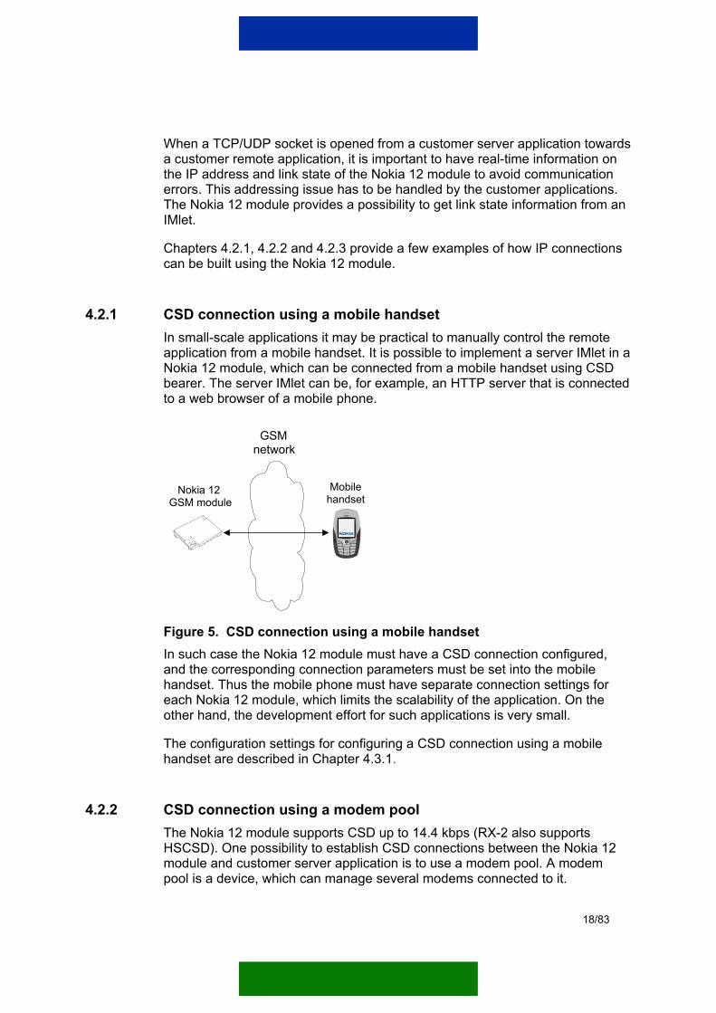
4.2.1 CSD connection using a mobile handset In small-scale applications it may be practical to manually control the remote application from a mobile handset. It is possible to implement a server IMlet in a Nokia 12 module, which can be connected from a mobile handset using CSD bearer. The server IMlet can be, for example, an HTTP server that is connected to a web browser of a mobile phone.
Nokia 12 GSM module
GSMnetwork
Mobile handset
Figure 5. CSD connection using a mobile handset In such case the Nokia 12 module must have a CSD connection configured, and the corresponding connection parameters must be set into the mobile handset. Thus the mobile phone must have separate connection settings for each Nokia 12 module, which limits the scalability of the application. On the other hand, the development effort for such applications is very small.
The configuration settings for configuring a CSD connection using a mobile handset are described in Chapter 4.3.1.
4.2.2 CSD connection using a modem pool The Nokia 12 module supports CSD up to 14.4 kbps (RX-2 also supports HSCSD). One possibility to establish CSD connections between the Nokia 12 module and customer server application is to use a modem pool. A modem pool is a device, which can manage several modems connected to it.
18/83

A modem pool can be located in the operator’s network or in the intranet. In both cases the network infrastructure has to be built so that it is possible to open sockets from the customer server application to Nokia 12 modules and vice versa. If the modem pool is hosted by the operator, as illustrated in Figure 6, technical solutions for the network infrastructure also depend on the operator, but generally routing, firewall rules and tunneling need to be handled.
Nokia 12 GSM module
GSMnetwork
PSTN/PLMN
Operator's network Internet
Modempool
Customerserver
application
Intranet
Figure 6. CSD connection with a modem pool in the operator's network If the modem pool is located in the intranet, as illustrated in Figure 7, network infrastructure, including routing and firewall rules, can be designed by the customer.
Nokia 12 GSM module
GSMnetwork
PSTN/ISDN
Modempool
Customerserver
application
Intranet
Figure 7. CSD connection with a modem pool in the intranet When a CSD connection is established between the Nokia 12 module and a modem pool, it is established as an analog data call. Therefore the modem pool can be equipped with analog modems that have PSTN lines connected to them. If several modems and lines are used, it is possible to have a private branch exchange (PBX) to ease the logic of call establishment. A PBX provides a
19/83

possibility to have one phone number to which all Nokia 12 modules are calling, and the PBX then forwards the call to one of the free lines that are connected to the modem pool.
HSCSD makes it possible to establish connections faster and have faster data rates when compared to CSD. It is possible to establish up to 28.8kbps analog data calls and up to 43.2kbps integrated services digital network (ISDN) data calls. An ISDN data call also provide faster connection establishment when compared to an analog data call. To be able to establish ISDN data calls from the Nokia 12 module to a modem pool, the modem pool needs to be equipped with modems that support ISDN v.110 or ISDN v.120 and have the corresponding ISDN lines.
Note: The availability of the HSCSD and ISDN data calls depend on the GSM operator.
GSM modems can also be used in the modem pool to provide GSM to GSM data calls. For more information, consult your GSM operator.
It is also possible to use a wake-up mechanism to command the Nokia 12 module to initiate a CSD connection. This is very useful in case it is not possible to dial a data call from a modem pool to the Nokia 12 module. For more detailed information about the Wake-Up Service (WUS), refer to Chapter 6.2.
For more information about configuring a CSD connection to the Nokia 12 module, refer to the Nokia M2M System Protocol 2 Socket Interface User Manual.
4.2.3 GPRS connection using GPRS access points Generally there are two different types of GPRS access points: public and private. Usually a public access point name (APN) is available for all mobile subscribers for connecting to the Internet and it is easy to take into use. However, a public APN has certain restrictions related to its usage and therefore a GSM operator may also provide a private APN, which offers more functionalities and a more secured access. Typically one private APN is dedicated for one company.
20/83

Nokia 12 GSM module
GSMnetwork
PrivateAPN
GGSN NAT/Firewall
Customerserver
application
PublicAPN
GGSN
Internet
Customerserver
application
1
2
Figure 8. IP traffic over GPRS using public or private access points As Figure 8 illustrates, a public APN can be used for opening sockets from the Nokia 12 module towards a customer server application, but the customer server application cannot open sockets towards the Nokia 12 module (1). This means that a customer remote application can open an IP connection towards the customer server application and the server application can respond to incoming packets, but the customer server application cannot open a new IP connection to the remote application. Depending on the application logic, this may be enough to establish adequate communication.
Because the public Internet APN provides a connection to the Internet, the customer server application computer must be connected to the Internet and it must have a public IP address. As the IP communication goes through the public Internet, it needs to be considered whether application level encryption is needed or not.
Two-way IP traffic between the Nokia 12 module and the customer server application is possible if the network operator provides a private APN with access to the network in which the customer server application is located (2). The network infrastructure between the private APN and customer server application has to be built so that it is possible to open sockets from the customer server application to the Nokia 12 modules and vice versa. Technical network infrastructure solutions depend on the GSM operator, but generally routing, firewall rules and tunnelling needs to be handled.
A customer server application can command the Nokia 12 module to open a GPRS connection by using WUS. For more detailed information about WUS, refer to Chapter 6.2.
When an IP connection is opened from a customer server application towards a remote application, it is important to know the IP address and link state information of the Nokia 12 module. To verify and identify a Nokia 12 module it
21/83

is also possible to query the IMEI code of the Nokia 12 module from an IMlet or from a customer server application.
4.3 WIRELESS BEARER CONFIGURATION The Nokia 12 module needs to be configured according to the used communication infrastructure. The configuration can be done either with the Configurator software or by using the CORBA interfaces of the Nokia 12 module.
There are two different sets of wireless bearer configurations in the Nokia 12 module: the HTTP settings and M2M bearer settings.
Only the Java HTTP API uses the HTTP settings. These settings include both the network link level settings and HTTP protocol -specific settings (such as proxy address) in the same configuration screen. These settings must be configured before an IMlet can use HTTP connections. This setup does not affect any other communication API than the HTTP API.
All other communication APIs, the Java Socket API, J2ME ORB and Module ORB, use the M2M bearer settings. These settings require only network link level configurations. The required configurations are:
• Username, password, and GPRS access point name in a GPRS case.
• Username, password and phone number in a CSD case. The HTTP API is unable to use the M2M bearer settings.
4.3.1 Configuring a CSD connection between the Nokia 12 GSM module and a mobile handset The configuration instructions presented in this chapter show an example configuration, in which a mobile handset opens a connection to the Nokia 12 module, as described in Chapter 4.2.1. This connection requires matching configurations both in the Nokia 12 module and in the mobile handset.
The Nokia 12 module must have a CSD connection configured. The general level configuration, illustrated in Figure 9, involves the setting of the username and password parameters for incoming call authentication.
Note: The setting of the incoming call authentication parameters is not mandatory, and thus the username and password can be left blank (for example when testing the CSD connection).
When using the Configurator software for the Nokia 12 module, the CSD connection parameters can be configured by choosing M2M System Mode -> Bearer Selection from the main menu.
22/83

Figure 9. General CSD connection configuration for the Nokia 12 GSM module
After the general level configuration, the default connection is set as TCP CSD as illustrated in Figure 10.
Figure 10. Default CSD connection for the Nokia 12 GSM module
Note: Other configuration values that are shown on the Configurator user interface (UI) are irrelevant in this case.
23/83

In addition to the previous configuration, the Nokia 12 module must know what IP address to use. Since the PPP link establishment between the mobile handset and the Nokia 12 module includes IP address negotiation for both ends, a unique IP address has to be configured for both devices.
For the Nokia 12 module the IP address configuration is done by choosing IMlet Loading -> Cable from the main menu as depicted in Figure 11.
Figure 11. IP address configuration for the Nokia 12 GSM module The mobile handset must be configured with the corresponding settings to be able to establish a CSD connection to the Nokia 12 module. How the mobile handset is configured varies according to the used device, but generally a new connection setting must be configured with the following parameters:
• Connection type is set to ‘datacall’.
• Destination phone number is set to match the number of the SIM card in the Nokia 12 module.
• Username and password are set, if they were configured to the Nokia 12 module.
• Start page (for example http://10.10.10.10) is set, if the IMlet is an HTTP server.
24/83

• Unique IP address is set for the mobile handset to be used in the PPP negotiation with the Nokia 12 module.
When the connection parameters are configured, the web browser of the mobile handset can connect to the Nokia 12 module using the configured connection settings.
4.3.2 Configuring a socket connection using CSD A CSD connection can be used through the M2M System Protocol 2 socket interface from an AM, or through the Socket API and ORB API from IMlet.
Note: The HTTP API uses a separately configured CSD connection. For more information, see Chapter 4.3.4.
The example CSD configuration in Figure 12 uses TCP as its transport layer to connect to a modem pool in number +0123456789. It also defines the username and password that are used in PPP negotiation with the modem pool.
When using the Configurator software for the Nokia 12 module, the CSD connection parameters can be configured by choosing M2M System Mode -> Bearer Selection from the main menu.
Note: In this example WUS is not used to open a CSD connection and thus some of the fields in Figure 12 are left empty. For more information on using WUS to open a CSD connection, see Chapter 6.2.
25/83

Figure 12. CSD connection configuration to a modem pool
4.3.3 Configuring a socket connection using GPRS The configuration instructions presented in this chapter are based on the network infrastructure illustrated in Figure 13.
Nokia 12 GSM module
GSMnetwork
GGSN
Internet
Customerserver
application
Private APN:example.com
Remote device
Local connectivity
Customerremote
application
Figure 13. IP traffic over GPRS using a private APN called 'example.com' A GPRS connection can be used through the M2M System Protocol 2 socket interface from an AM, or through the Socket API and ORB API from an IMlet.
Note: The HTTP API uses a separately configured GPRS connection. For more information, see Chapter 4.3.4.
26/83

information, see Chapter 4.3.4.
The example GPRS configuration in Figure 14 uses TCP as its transport layer to connect to a private APN called ‘example.com’. It also defines the username and password that are used in PPP negotiation with the operator’s GGSN.
When using the Configurator software for the Nokia 12 module, the GPRS connection parameters can be configured by choosing M2M System Mode -> Bearer Selection from the main menu.
Note: In this example WUS is not used to open a GPRS context and thus some of the fields in Figure 14 are left empty. For more information on using WUS to open a GPRS context, see Chapter 6.2.
Figure 14. GPRS connection configuration to the private APN 'example.com'
4.3.4 Configuring an HTTP connection using GPRS and CSD An HTTP connection can be used only through the HTTP API from an IMlet. It does not affect the connections used through the M2M System Protocol 2 socket interface from an AM, or through socket API and ORB API from IMlet.
When using the Configurator software for the Nokia 12 module, the HTTP connection parameters can be configured by choosing File -> Module Configuration -> HTTP Settings from the main menu.
27/83

The example HTTP configuration in Figure 15 uses GPRS connection to connect to a public APN, typically called Internet. The username and password are left blank, as they typically are when connecting to a public APN. The login type must be ‘automatic’, and session security must be ‘normal’.
Figure 15. HTTP connection configuration to a public APN The example HTTP configuration in Figure 16 uses a CSD connection to connect to an analog modem pool in number +0123456789. The username and password are left blank. The login type must be ‘automatic’, and session security must be ‘normal’.
28/83

Figure 16. HTTP connection configuration to a modem pool
Note: You must verify your actual HTTP connection parameters, both for GPRS and CSD, from your GSM operator.
29/83

5 M2M APPLICATION DEVELOPMENT AND DEPLOYMENT EXAMPLE
5.1 INTRODUCTION This chapter provides a thorough example case of how a Nokia 12 module can be configured and how an M2M application in an IMlet Suite can be deployed to that module. The technical details of each step leading to the application deployment are described in the following chapters.
The process described here is a product deployment example for one M2M application. The purpose of the example is to give the reader an overall picture of why certain services exist and where they can be used. Basic IMlet development is also covered because the deployment process must usually be taken into account at the IMlet development phase.
This is only an example case, and thus some customer-specific adjustments to this process are usually needed. Some external server side applications are also required to take all options into use.
Note: Depending on the application scale and requirements, an application developer can select the parts of this example that are relevant for him/her, and utilize them in the development process.
5.2 APPLICATION DEVELOPMENT AND DEPLOYMENT CHARACTERISTICS This chapter provides a general level description of the steps that an application development and deployment process typically includes.
5.2.1 Example scenario This example scenario deals with a server application, which manages multiple measurement units (referred here simply as devices). Each device includes measurement hardware, a Nokia 12 module, a SIM card and an antenna, all packed as a single unit.
The server application manages thousands of devices, which are geographically distributed on a wide area. The installation locations are referred to as sites. Each device sends measurement data periodically to the server application. The server application can also initiate measurement reading immediately if management personnel require updated information.
For the system to be economical and logistically manageable, it has to meet the following requirements:
30/83

• Devices are produced in large production batches. After the production, devices are stored and waiting for the field deployment. Communication settings are not known at the time of production. The final installation location of the device is not known at the time of production.
• GSM subscriptions and SIM cards are purchased from GSM operator only when devices are taken into use in the field. For economical reasons GSM subscriptions and SIM cards are not purchased during the device production phase. The service personnel install the SIM cards to the devices at the installation stage.
• The on-site installation of the devices must be very simple and error free. Manual configuration tasks are to be avoided.
• Because devices collect measurement information from different sites, each device must be identifiable. The device sends this identification information each time it delivers measurements to the server. Some site-specific parametrization is also required for each device.
• Devices must be remotely manageable. After installation there should be no need for on-site visits by the service personnel. Remote software updates must also be feasible.
• Security must be handled so that only the dedicated server application can have access to the devices. Each device must have unique security settings. If one device is stolen its authentication information can be simply removed from the authentication server without affecting the other devices. Auto PIN feature of the Nokia 12 module is used to ensure that the SIM card is usable only with the module that it is installed to.
The list above presents quite a challenging set of requirements for the system. The following chapters show how the Nokia 12 module can be used to meet these requirements.
5.2.2 Overall process Figure 17 illustrates the overall application development and deployment process for the example scenario presented in Chapter 5.2.1.
31/83

Product development
Production
On-site deploymentOver-the-air configuration
IMletdevelopment
Initial setup using smart message
Product installation
IMlet installation
Module configuration
Wake-up (CSD/GPRS)
Product integration
Hardwaredevelopment
Mass production
Storage & deployment
1.
2.
5.
4.
6.
7.
Operational phaseRemote management
IMlet update
Module configuration change
8.
3.
Prototyping, testing, pilot installations
Serverdevelopment
Figure 17. Overall development and deployment process for the example scenario
32/83

The process is divided to four stages: product development (step 1), production (step 2), onsite installation (steps 3-7) and operational phase (step 8).
5.2.3 Product development IMlets and device hardware are designed at the product development phase (1). The Simulator is used in initial IMlet development and the final software is tested using the Nokia 12 module and the Nokia 12 test board. First prototypes are built on the Nokia 12 test board so that software development can proceed before the hardware development is ready.
There is no need to hard-code configuration values, such as identification information, wireless bearer settings, and server address, into IMlet code. An IMlet can access the Nokia 12 module configuration and use the information found there. Most Java communication APIs use communication settings configured into the Nokia 12 module.
The Nokia 12 module provides interfaces to remotely handle all these configurations so that devices can be mass-produced without any device-specific configuration information. Device-specific configurations will be set remotely at the product installation phase.
The Configurator is used to set the configuration values at the development and prototyping phase. Remote configuration approach is used later at the operational phase.
The server application is developed to take use of the Nokia 12 module remote management services, over-the-air configuration, wake-up and remote IMlet loading. These services are needed later in the mass deployment stage.
For more information about accessing the module settings from IMlet code, see the Nokia 12 GSM Module Properties Reference Guide, Nokia 12 GSM Module Interface Reference Guide and Nokia 12 GSM Module JavaTM IMlet Programming Guide. See also the example IMlets available in the Nokia 12 SDK.
5.2.4 Production Because it is not mandatory to install IMlets into the Nokia 12 module at the device production phase (2), the remote installation option was chosen. In this example an IMlet will be installed later in the deployment phase using the IMlet Suite Manager service remotely.
There is no need to install IMlets in the device production phase. This ensures that the latest version of the software will be installed when the device is installed on the site.
33/83

5.2.5 On-site deployment When lots of units are taken into use, an automated installation process is needed. The device-specific configuration values, such as identification information, need to be to set, but in general other on-site manual configuration should be avoided.
At the installation site (3) the SIM card is attached to the device, an antenna is fitted and correctly located, and the device is powered up. After this the installation proceeds automatically and the server application needs only the phone number of the SIM card to continue installation. The service personnel inform the service application about the installed device, after which the automatic installation procedure starts.
The server application does the initial configuration using a smart message (4). This specially designed short message can be used to set up the configuration for up to 2 wireless bearers. A smart message is used to set up bootstrap connection information (for example, one GPRS and one wake-up bearer).
Note: It is not possible to set all configuration parameters using a smart message.
See Chapter 6.1 for more information on using smart messages.
After a bootstrap connection is set, the IP connection from the server application to the Nokia 12 module is possible. At this point the server application sends a wake-up short message to the Nokia 12 module (5). The Nokia 12 module opens a GPRS link and sends an acknowledgement message to the server application using the established GPRS link. Now the server application can see that the IP-based communication towards the Nokia 12 module is possible, and it can continue the set-up process.
There is an ID field available in wake-up request message, which the server application can use to identify an opened connection. The Nokia 12 module uses the same ID number in the acknowledgement message that it sends over GPRS.
Note: GPRS wake-up is used in this example, but CSD wake-up is also possible.
For detailed information about the Wake-Up Service, see Chapter 6.2.
Rest of the configurations (6) are done over a GPRS bearer. At this point all the remaining wireless bearer settings are configured, and it now it is also possible to modify the factory settings of the Nokia 12 module.
In this example the PIN code of the SIM card is changed, and the Auto PIN feature is activated to improve security. Module ORB is set to IIOP mode to
34/83

enable remote IMlet loading. CSD bearer settings are installed to enable backup connections by using a data call bearer. This example system is designed to operate with a GPRS bearer, but a CSD bearer is reserved as a backup communication method in case the GPRS connection to the Nokia 12 module is not possible.
Note: After the configuration updates the Nokia 12 module is restarted to take new settings into use. Like configurations, also restart can be invoked remotely.
After the Nokia 12 module is fully configured (7), the M2M application inside an IMlet Suite is taken into use in the Nokia 12 module. Deployment is done over- the-air using the IMlet Suite Manager Interface of the Module ORB (see Chapter 6.4 for details). After successful installation, the server application starts the IMlet and checks that the IMlet has started successfully. The deployment of the IMlet is done after all Nokia 12 module configurations are ready. This ensures that the IMlet can start its duties immediately from the first start.
The last installation step is to set the site-specific parameters to the IMlet. A remotely available API implemented into the IMlet can be used to set the site-specific parameters. The server application calls this API to set the site-specific parameters. The IMlet stores these parameters into non-volatile memory using the Java RMS API.
At this point the installation phase is complete. When the Nokia 12 module restarts, the IMlet starts its autonomous operations and sends the measurement results to the server application periodically.
Note: If there is a need for the server application to read measurement data during times that deviate from the periodical schedule, it can send a wake-up message to the Nokia 12 module and command the IMlet in question to send a data update immediately.
5.2.6 Operational phase Sometimes it is necessary to modify communication settings when the device is already in use (8). For example, the IP address of the server application changes or there is need to change authentication passwords. There may also be a need to update new IMlets into the Nokia 12 module. As in the initial setup, the configuration interface can be used to change the Nokia 12 module configuration, and the IMlet Suite Manager service can be used to update IMlets.
It is also possible to invoke management operations from the server application during the operational phase. These operations are used to solve detected communication problems. The server application can, for example, query IMlet status or ask for certain parameter values from the Nokia 12 module. There are certain useful parameters available in the Nokia 12 module, which can be used
35/83
to detect causes for possible communication problems. A good example is the SignalQuality parameter, which measures the GSM signal quality.
When the server application needs to query parameters from the Nokia 12 module, it first sends a wake-up message to the Nokia 12 module to open a GPRS link. After the GPRS link is open the server application can, for example, query IMlet status or ask for parameter values, such as the GSM signal quality, from the Nokia 12 module. See the Nokia 12 GSM Module Properties Reference Guide for a list of available parameters.
36/83

6 NOKIA 12 GSM MODULE REMOTE MANAGEMENT
6.1 INITIAL REMOTE CONFIGURATION This chapter gives instructions on how to remotely configure the initial configuration for the Nokia 12 module. The configuration is done by using smart message(s), sent in a binary short message, or series of binary short messages.
Note: The Nokia 12 module can also be configured locally by using the Configurator software.
6.1.1 Basic functionality The short messages are sent to the Wireless Datagram Protocol (WDP) port 49999 of the Nokia 12 module. The messages contain a WDP layer, Wireless Session Protocol (WSP) layer, and Wireless Binary Extensible Markup Language (WBXML) data. The WBXML data contains the configuration information.
With remote configuration, one general bearer and one SMS bearer can be configured to the Nokia 12 module. Typically, the SMS bearer is set with the general bearer in order to enable WUS.
In order for the initial remote configuration to succeed, there must be no configured bearers in the Nokia 12 module. Otherwise the configuration will fail silently. This also means that only one successful configuration can be sent to the Nokia 12 module. The initial configuration will also fail if a configuration value is out of range.
The smart messaging data holds its information in a list of characteristics, coded as WBXML data. This information is used to configure the Nokia 12 module.
The structure of a characteristic list is described in Figure 18.
37/83

Characteristic list
Characteristic [TYPE A]
Parameter [NAME=X] [VALUE=Y]
Parameter [NAME=V] [VALUE=W]
...
Characteristic [TYPE B]
Parameter [NAME=Q] [VALUE=P]
Parameter [NAME=X] [VALUE=Y]
...
...
Figure 18. The structure of a characteristic An example of a characteristic list in XML format:
<?xml version=”1.0”> <!DOCTYPE CHARACTERISTIC-LIST SYSTEM “/DTD/characteristic_list.xml”> <CHARACTERISTIC-LIST> <CHARACTERISTIC TYPE=”GATEWAY_CONNECTION”> <PARM NAME=”BEARER” VALUE=”BEARER_CSD”/> <PARM NAME=”GATEWAY_PORT” VALUE=”9200”/> <PARM NAME=”GATEWAY_NUMBER” VALUE=”+0123456789”/> <PARM NAME=”GATEWAY_IPADDRESS” VALUE=”192.168.1.1”/> <PARM NAME=”PPP_AUTHNAME_GW” VALUE=”myUsername”/> <PARM NAME=”PPP_AUTHSECRET_GW” VALUE=”myPassword”/> <PARM NAME=”HLA_IPADDRESS” VALUE=”192.168.1.2”> <PARM NAME=”HLA_PORT” VALUE=”19680”> </CHARACTERISTIC> <CHARACTERISTIC TYPE=”CONNECTION”> <PARM NAME=”ET_PORT” VALUE=”1”/> <PARM NAME=”TIMEOUT_SEC” VALUE=”5”/> <PARM NAME=”BITRATE_CSD” VALUE=”9600”/> </CHARACTERISTIC> </CHARACTERISTIC-LIST>
38/83

6.1.2 Nokia 12 GSM module settings This chapter presents the information needed for coding smart messages. Chapter 6.1.2.1 presents example configurations, and describes the parameters that are used in the examples. Chapter 6.1.2.2 lists all the configurable parameters, and provides additional information needed for coding smart messages.
6.1.2.1 Example configurations This chapter presents configuration examples, in which smart messages are used to configure wireless bearers to the Nokia 12 module. The smart message examples presented in this chapter correspond to Configurator examples presented in Chapters 4.3 and 6.2.2.1.
The parameters used in the configuration examples are described after the examples. It is also indicated whether the parameters used in the examples are mandatory or not. Chapter 6.1.2.2 lists all the configurable parameters and the values they can be given.
Note: There are two types of characteristics in the examples: CONNECTION and GATEWAY_CONNECTION. The CONNECTION type parameters typically configure the same values that are configured via the General tab when using the Configurator software. The GATEWAY_CONNECTION type parameters typically configure the bearer-specific values that are configured via the Connection tabs when using the Configurator software.
Configuring a CSD connection between the Nokia 12 GSM module and a mobile handset In the following example a smart message is used to configure a CSD connection between the Nokia 12 module and a mobile handset.
Note: The same configuration is done with the Configurator software in Chapter 4.3.1.
<?xml version=”1.0”> <!DOCTYPE CHARACTERISTIC-LIST SYSTEM “/DTD/characteristic_list.xml”> <CHARACTERISTIC-LIST> <CHARACTERISTIC TYPE=”GATEWAY_CONNECTION”> <PARM NAME=”BEARER” VALUE=”BEARER_CSD”/> </CHARACTERISTIC> <CHARACTERISTIC TYPE=”CONNECTION”> <PARM NAME=”ET_PORT” VALUE=”0”/> <PARM NAME=”PPP_AUTHNAME_ET” VALUE=”myUsername”/> <PARM NAME=”PPP_AUTHSECRET_ET” VALUE=”myPassword”/> </CHARACTERISTIC> </CHARACTERISTIC-LIST>
39/83

Table 1. Parameters used for configuring a CSD connection between the Nokia 12 GSM module and a mobile handset
Parameter name Description Mandatory
BEARER Defines the used bearer, CSD in this example.
Yes
ET_PORT A legacy parameter that has no real effect. The value of this parameter can be defined as 0 (zero).
No
PPP_AUTHNAME_ET Authentication username for mobile terminated call.
Yes
PPP_AUTHSECRET_ET Authentication password for mobile terminated call.
Yes
Configuring a socket connection using CSD In the following example a smart message is used to configure a CSD socket connection.
Note: The same configuration is done with the Configurator software in Chapter 4.3.2.
<?xml version=”1.0”> <!DOCTYPE CHARACTERISTIC-LIST SYSTEM “/DTD/characteristic_list.xml”> <CHARACTERISTIC-LIST> <CHARACTERISTIC TYPE=”GATEWAY_CONNECTION”> <PARM NAME=”BEARER” VALUE=”BEARER_CSD”/> <PARM_NAME=”DESTINATION_NUMBER” VALUE=”+0123456789”> <PARM NAME=”PPP_AUTHNAME_GW” VALUE=”myUsername”/> <PARM NAME=”PPP_AUTHSECRET_GW” VALUE=”myPassword”/> </CHARACTERISTIC> <CHARACTERISTIC TYPE=”CONNECTION”> <PARM NAME=”ET_PORT” VALUE=”0”/> </CHARACTERISTIC> </CHARACTERISTIC-LIST>
Table 2. Parameters used for configuring a CSD socket connection
Parameter name Description Mandatory
BEARER Defines the used bearer, CSD in this example.
Yes
DESTINATION_NUMBER The number that the Nokia 12 module calls when the link is opened. Typically the number will connect to a modem pool.
Yes
PPP_AUTHNAME_GW The bearer-specific username for the server (gateway), used in authentication.
Yes
40/83

Parameter name Description Mandatory
PPP_AUTHSECRET_GW The bearer-specific password for the server, used in authentication.
Yes
ET_PORT A legacy parameter that has no real effect. The value of this parameter can be defined as 0 (zero).
No
Configuring a socket connection using GPRS In the following example a smart message is used to configure a GPRS socket connection.
Note: The same configuration is done with the Configurator software in Chapter 4.3.3.
<?xml version=”1.0”> <!DOCTYPE CHARACTERISTIC-LIST SYSTEM “/DTD/characteristic_list.xml”> <CHARACTERISTIC-LIST> <CHARACTERISTIC TYPE=”GATEWAY_CONNECTION”> <PARM NAME=”BEARER” VALUE=”BEARER_GPRS”/> <PARM_NAME=”GPRS_ACCESSPOINT_NAME” VALUE=”example.com”> <PARM NAME=”PPP_AUTHNAME_GW” VALUE=”myUsername”/> <PARM NAME=”PPP_AUTHSECRET_GW” VALUE=”myPassword”/> </CHARACTERISTIC> <CHARACTERISTIC TYPE=”CONNECTION”> <PARM NAME=”ET_PORT” VALUE=”0”/> </CHARACTERISTIC> </CHARACTERISTIC-LIST>
Table 3. Parameters used for configuring a GPRS socket connection
Parameter name Description Mandatory
BEARER Defines the used bearer, GPRS in this example.
Yes
GPRS_ACCESSPOINT_NAME
The GPRS access point. This is the address that the Nokia 12 module connects to when the connection is opened.
Yes
PPP_AUTHNAME_GW The bearer-specific username for the server (gateway), used in authentication.
Yes
PPP_AUTHSECRET_GW The bearer-specific password for the server, used in authentication.
Yes
ET_PORT A legacy parameter that has no real effect. The value of this parameter can be defined as 0
No
41/83

Parameter name Description Mandatory (zero).
Configuring a GPRS connection and an additional WUS SMS bearer The following configuration describes how to configure a GPRS connection and an additional WUS SMS bearer by using a smart message.
Note: The same configuration is done with the Configurator software in Chapter 6.2.2.1.
<?xml version=”1.0”> <!DOCTYPE CHARACTERISTIC-LIST SYSTEM “/DTD/characteristic_list.xml”> <CHARACTERISTIC-LIST> <CHARACTERISTIC TYPE=”GATEWAY_CONNECTION”> <PARM NAME=”BEARER” VALUE=”BEARER_GPRS”/> <PARM_NAME=”GPRS_ACCESSPOINT_NAME” VALUE=”example.com”> <PARM NAME=”PPP_AUTHNAME_GW” VALUE=”myUsername”/> <PARM NAME=”PPP_AUTHSECRET_GW” VALUE=”myPassword”/> <PARM NAME=”BEARER_SMS” VALUE=”BEARER_SMS”/> <PARM NAME=”DESTINATION_NUMBER_SMS” VALUE=”+9876543210”/> </CHARACTERISTIC> <CHARACTERISTIC TYPE=”CONNECTION”> <PARM NAME=”ET_PORT” VALUE=”0”/> </CHARACTERISTIC> </CHARACTERISTIC-LIST>
Table 4. Parameters used for configuring a GPRS connection and an additional WUS SMS bearer
Parameter name Description Mandatory
BEARER Defines the used bearer, GPRS in this example.
Yes
GPRS_ACCESSPOINT_NAME
The GPRS access point. This is the address that the Nokia 12 module connects to when the connection is opened.
Yes
PPP_AUTHNAME_GW The bearer-specific username for the server (gateway), used in authentication.
Yes
PPP_AUTHSECRET_GW The bearer-specific password for the server, used in authentication.
Yes
BEARER_SMS This defines the WUS bearer of the connection. This is always defined as BEARER_SMS.
Yes
DESTINATION_NUMBER_SMS
This defines the phone number from which the wake-up short message is sent. The wake-up
Yes
42/83

Parameter name Description Mandatory message must come from this number for the Nokia 12 module to accept it.
ET_PORT A legacy parameter that has no real effect. The value of this parameter can be defined as 0 (zero).
No
Configuring a single SMS bearer The final example shows how to configure a single SMS bearer by using a smart message.
Note: This example differs from the WUS SMS bearer configuration example. With the WUS SMS bearer, the BEARER_SMS of the GATEWAY_CONNECTION was defined as BEARER_SMS. Here the BEARER of the GATEWAY_CONNECTION is defined as BEARER_SMS.
<?xml version=”1.0”> <!DOCTYPE CHARACTERISTIC-LIST SYSTEM “/DTD/characteristic_list.xml”> <CHARACTERISTIC-LIST> <CHARACTERISTIC TYPE=”GATEWAY_CONNECTION”> <PARM NAME=”BEARER” VALUE=”BEARER_SMS”/> <PARM NAME=”GATEWAY_PORT” VALUE=”9200”/> <PARM NAME=”DESTINATION_NUMBER” VALUE=”+0123456789”/> </CHARACTERISTIC> <CHARACTERISTIC TYPE=”CONNECTION”> <PARM NAME=”ET_PORT” VALUE=”0”/> </CHARACTERISTIC> </CHARACTERISTIC-LIST>
Table 5. Parameters used for configuring a single SMS bearer
Parameter name Description Mandatory
BEARER Defines the used bearer, SMS in this example.
Yes
GATEWAY_PORT Port of the server (gateway). Yes
DESTINATION_NUMBER The number to which the SMS bearer sends the short messages.
Yes
ET_PORT A legacy parameter that has no real effect. The value of this parameter can be defined as 0 (zero).
No
43/83

6.1.2.2 Configuration parameters in characteristics This chapter lists all the configurable parameters and the values they can have. At the end of the chapter there are tables that present the hexadecimal values that are needed when coding the real message to be sent.
Table 6 and Table 7 include a full list of configurable parameters that can be used in configurations. The size defines how long the parameter can be in bytes. Table 6 lists the parameters coded according to the GATEWAY_CONNECTION (G) characteristic, and Table 7 lists the parameters coded according to the CONNECTION (C) characteristic.
Table 6. Configurable parameters (GATEWAY_CONNECTION)
Parameter Size / bytes
Bearers Description Char. type
BEARER 1 All SMS | CSD | GPRS G
BEARER_SMS 1 CSD and GPRS
When this is set to BEARER_SMS, it defines the WUS SMS bearer of that connection.
G
DESTINATION_NUMBER_SMS
40 SMS The SMS number for the WUS.
G
GATEWAY_IPADDRESS
4 CSD and GPRS
Server (gateway) IP address.
G
GATEWAY_NUMBER
40 CSD Gateway MSISDN G
GATEWAY_PORT
2 All The server port. This information is very often used with WUS.
G
HLA_IPADDRESS
4 All A legacy parameter that has no real effect. Can be used optionally to store additional server information.
G
HLA_PORT 2 All A legacy parameter that has no real effect. Can be used optionally to store additional server information.
G
Table 7. Configurable parameters (CONNECTION)
Parameter Size / bytes
Bearers Description Char. type
44/83

Parameter Size / bytes
Bearers Description Char. type
BITRATE_CSD 1 CSD Used bitrate for a CSD-link.
C
DESTINATION_NUMBER
40 SMS Destination MSISDN, SMSC number.
C
ET_PORT 2 All A legacy parameter that has no real effect. The value of this parameter can be defined as 0 (zero).
C
ET_PORT_SMS 2 SMS This defines the WTP port of the WUS SMS bearer.
C
GPRS_ACCESSPOINT_NAME
100 GPRS Access Point Name for GPRS
C
TIMEOUT_SEC 4 CSD and GPRS
Timeout value for wireless link in seconds, range 0 – 300 s.
C
Some of the configuration parameters have only a few predefined values that map to the prefixed hexadecimal values. If there are no prefixed values, the values are coded as strings. Chapter 6.1.3.3 gives instructions on how to code a smart message in WBXML format using the prefixed values and strings.
Table 8 and Table 9 define the parameter values for the two characteristic types.
Table 8. Parameter names for the CONNECTION type
Parameter names for the CONNECTION type
Parameter values
BITRATE_CSD 9600, 14400, 19200, 28800, 38400, 43200
ET_PORT String
TIMEOUT_SEC String
DESTINATION_NUMBER String
GPRS_ACCESSPOINT_NAME String
PPP_AUTHNAME_ET String
PPP_AUTHSECRET_ET String
ET_PORT_SMS String
Table 9. Parameter names for the GATEWAY_CONNECTION type
45/83

Parameter names for the GATEWAY_CONNECTION type
Parameter values
BEARER BEARER_CSD, BEARER_SMS, BEARER_GPRS
GATEWAY_PORT String
GATEWAY_NUMBER String
GATEWAY_IPADDRESS String
HLA_IPADDRESS String
HLA_PORT String
PPP_AUTHNAME_GW String
PPP_AUTHSECRET_GW String
BEARER_SMS String
GATEWAY_PORT_SMS String
DESTINATION_NUMBER_SMS String
Table 10 and Table 11 hold the hexadecimal values needed when coding the message. The example in Chapter 6.1.4 uses these values to code a configuration message.
Table 10 lists three global tokens that are used to separate information units.
Table 10. Global tokens
Global token name Token value
END 0x01
INLINE_STRING 0x03
END_INLINE_STRING 0x00
Table 11. Attribute tokens
Attribute name Attribute value prefix Token value
TYPE ADDRESS 0x06
TYPE NAME 0x07
TYPE GATEWAY_CONNECTION 0x09
NAME* 0x10
VALUE** 0x11
NAME BEARER 0x12
46/83

Attribute name Attribute value prefix Token value
TYPE CONNECTION 0x13
NAME GPRS_ACCESSPOINT_NAME
0x1C
NAME PPP_AUTHNAME_GW 0x23
NAME PPP_AUTHSECRET_GW 0x24
NAME PPP_AUTHNAME_ET 0x25
NAME PPP_AUTHSECRET_ET 0x26
NAME BEARER_SMS 0x27
NAME GATEWAY_PORT_SMS 0x28
NAME ET_PORT_SMS 0x29
NAME DESTINATION_NUMBER_SMS
0x30
NAME GATEWAY_PORT 0x50
NAME GATEWAY_NUMBER 0x51
NAME GATEWAY_IPADDRESS 0x52
NAME ET_PORT 0x53
NAME TIMEOUT_SEC 0x54
NAME BITRATE_CSD 0x55
NAME DESTINATION_NUMBER 0x57
VALUE BEARER_SMS 0x58
VALUE BEARER_CSD 0x59
VALUE BEARER_GPRS 0x61
VALUE 9600 0x6B
VALUE 14400 0x6C
VALUE 19200 0x6D
VALUE 28800 0x6E
VALUE 38400 0x6F
VALUE 43200 0x74
VALUE 57600 0x75
NAME HLA_IPADDRESS 0x76
NAME HLA_PORT 0x77
*The NAME attribute indicates the beginning of the NAME field. ** The VALUE attribute indicates the beginning of the VALUE field.
47/83

6.1.3 Structure of a smart message This chapter describes the structure of a smart message. The message consists of a WSP header and a list of characteristics.
6.1.3.1 Wireless Session Protocol header A smart message starts with a WSP header that holds the Multi-purpose Internet Mail Extension (MIME) type. The MIME type is coded as a string.
Note: Do not edit the WSP header bytes unless specified differently.
Table 12. Wireless Session Protocol header bytes
Value Description
0x01 Transaction ID. Can be changed if necessary.
0x06 PDU type, ‘push’.
0x2C Header length
0x1F A value indicating that the header is longer that 30 bytes.
0x2A Value length
0x61 0x70 0x70 0x6C 0x69 0x63 0x61 0x74 0x69 0x6F 0x6E 0x2F 0x78 0x2D 0x77 0x61 0x70 0x2D 0x70 0x72 0x6F 0x76 0x2E 0x6E 0x6F 0x6B 0x69 0x61 0x33 0x30 0x2D 0x73 0x65 0x74 0x74 0x69 0x6E 0x67 0x73
String application/x-wap-prov.nokia30-settings
0x00 Null terminator of the string
0x81 Charset, UTF-8
0xEA End of the WSP header.
6.1.3.2 Message body The actual message starts right after the header with a few bytes that are always the same.
Table 13. Message body
Value Description
0x01 Version, WBXML 1.1
0x01 Unknown public identifier
0x6A Charset, UTF-8
48/83
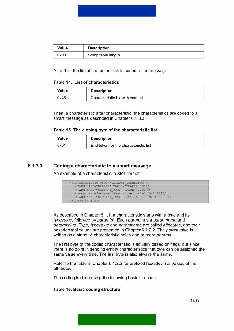
Value Description
0x00 String table length
After this, the list of characteristics is coded to the message.
Table 14. List of characteristics
Value Description
0x45 Characteristic list with content
Then, a characteristic after characteristic, the characteristics are coded to a smart message as described in Chapter 6.1.3.3.
Table 15. The closing byte of the characteristic list
Value Description
0x01 End token for the characteristic list
6.1.3.3 Coding a characteristic to a smart message An example of a characteristic in XML format:
<CHARACTERISTIC TYPE=”GATEWAY_CONNECTION”> <PARM NAME=”BEARER” VALUE=”BEARER_CSD”/> <PARM NAME=”GATEWAY_PORT” VALUE=”9200”/> <PARM NAME=”GATEWAY_NUMBER” VALUE=”+0123456789”/> <PARM NAME=”GATEWAY_IPADDRESS” VALUE=”192.168.1.1”/> </CHARACTERISTIC>
As described in Chapter 6.1.1, a characteristic starts with a type and its typevalue, followed by param(s). Each param has a paramname and paramvalue. Type, typevalue and paramname are called attributes, and their hexadecimal values are presented in Chapter 6.1.2.2. The paramvalue is written as a string. A characteristic holds one or more params.
The first byte of the coded characteristic is actually based on flags, but since there is no point in sending empty characteristics that byte can be assigned the same value every time. The last byte is also always the same.
Refer to the table in Chapter 6.1.2.2 for prefixed hexadecimal values of the attributes.
The coding is done using the following basic structure:
Table 16. Basic coding structure
49/83

Value Description
0xC6 Start byte, characteristic with content and attributes
<TYPE_NAME-Attribute> For example, GATEWAY_CONNECTION
<END>
For params, the parameter name is a prefixed value, but the parameter value can be either a prefixed value or a string:
Table 17. Prefixed parameter value
Value Description
0x87 Parameter with attributes
<PARAM_NAME-Attribute> Example: BEARER
<PARAM_NAME-Attribute> Example: BEARER_GPRS
<END> End of the parameter
Table 18. String parameter value
Value Description
0x87 Parameter with attributes
<PARAM_NAME-Attribute> Example: BEARER
<VALUE-Attribute> A flag for starting the value
<INLINE_STRING> Begin a string value
<string as bytes>
<END_INLINE_STRING> End of the string value
<END> End of the parameter
Table 19. Final byte (end of the characteristic)
Value Description
<END> End of characteristic.
6.1.4 Example message coded as a smart message In this chapter an example configuration message is coded to a smart message that can be sent in a binary short message.
50/83

The example message in XML format:
<?xml version=”1.0”> <!DOCTYPE CHARACTERISTIC-LIST SYSTEM “/DTD/characteristic_list.xml”> <CHARACTERISTIC-LIST> <CHARACTERISTIC TYPE=”GATEWAY_CONNECTION”> <PARM NAME=”BEARER” VALUE=”BEARER_CSD”/> <PARM NAME=”GATEWAY_PORT” VALUE=”9200”/> <PARM NAME=”GATEWAY_NUMBER” VALUE=”+0123456789”/> <PARM NAME=”GATEWAY_IPADDRESS” VALUE=”192.168.1.1”/> <PARM NAME=”HLA_IPADDRESS” VALUE=”192.168.1.2”> <PARM NAME=”HLA_PORT” VALUE=”19680”> </CHARACTERISTIC> <CHARACTERISTIC TYPE=”CONNECTION”> <PARM NAME=”ET_PORT” VALUE=”0”/> <PARM NAME=”TIMEOUT_SEC” VALUE=”5”/> <PARM NAME=”BITRATE_CSD” VALUE=”9600”/> <PARM NAME=”PPP_AUTHNAME_ET” VALUE=”myUsername”/> <PARM NAME=”PPP_AUTHSECRET_ET” VALUE=”myPassword”/> </CHARACTERISTIC> </CHARACTERISTIC-LIST>
Table 20. The example message coded in WBXML format (starting from the WSP header)
Hex value Meaning Description
0x01 Transaction ID WSP layer (start WSP headers)
0x06 PDU type (push)
0x2C Headers’ length
0x1F Length greater than 30
0x2A Value length
0x61 0x70 0x70 0x6C 0x69 0x63 0x61 0x74 0x69 0x6F 0x6E 0x2F 0x78 0x2D 0x77 0x61 0x70 0x2D 0x70 0x72 0x6F 0x76 0x2E 0x6E 0x6F 0x6B 0x69 0x61 0x33 0x30 0x2D 0x73 0x65 0x74 0x74 0x69 0x6E 0x67 0x73
String: application/x-wap-prov.nokia30-settings
MIME type
0x00 Null termination of content type
0x81 Charset
0xEA UTF-8 WSP layer (end WSP headers)
0x01 Version WBXML 1.1
0x01 Unknown public identifier
51/83
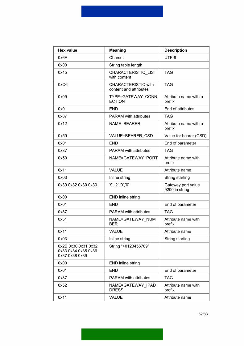
Hex value Meaning Description
0x6A Charset UTF-8
0x00 String table length
0x45 CHARACTERISTIC_LIST with content
TAG
0xC6 CHARACTERISTIC with content and attributes
TAG
0x09 TYPE=GATEWAY_CONNECTION
Attribute name with a prefix
0x01 END End of attributes
0x87 PARAM with attributes TAG
0x12 NAME=BEARER Attribute name with a prefix
0x59 VALUE=BEARER_CSD Value for bearer (CSD)
0x01 END End of parameter
0x87 PARAM with attributes TAG
0x50 NAME=GATEWAY_PORT Attribute name with prefix
0x11 VALUE Attribute name
0x03 Inline string String starting
0x39 0x32 0x30 0x30 ‘9’,’2’,’0’,’0’ Gateway port value 9200 in string
0x00 END inline string
0x01 END End of parameter
0x87 PARAM with attributes TAG
0x51 NAME=GATEWAY_NUMBER
Attribute name with prefix
0x11 VALUE Attribute name
0x03 Inline string String starting
0x2B 0x30 0x31 0x32 0x33 0x34 0x35 0x36 0x37 0x38 0x39
String “+0123456789”
0x00 END inline string
0x01 END End of parameter
0x87 PARAM with attributes TAG
0x52 NAME=GATEWAY_IPADDRESS
Attribute name with prefix
0x11 VALUE Attribute name
52/83

Hex value Meaning Description
0x03 Inline string String starting
0x31 0x39 0x32 0x2E 0x31 0x36 0x38 0x2E 0x31 0x2E 0x31
String: “192.168.1.1“ IP address in string notation
0x00 END inline string
0x01 END End of parameter
0x87 PARAM with attributes TAG
0x76 NAME=HLA_IPADDRESS Attribute name with prefix
0x11 VALUE Attribute name
0x03 Inline string String starting
0x31 0x39 0x32 0x2E 0x31 0x36 0x38 0x2E 0x31 0x2E 0x32
String: “192.168.1.2” IP address in string notation
0x00 END inline string
0x01 END End of parameter
0x87 PARAM with attributes TAG
0x77 NAME=HLA_PORT Attribute name with prefix
0x11 VALUE Attribute name
0x03 Inline string String starting
0x31 0x39 0x36 0x38 0x30
String: “19680” HLA port value 19680 in string
0x00 END inline string
0x01 END End of parameter
0x01 END End of characteristic
0xC6 CHARACTERISTIC with content and attributes
TAG
0x13 TYPE=CONNECTION Attribute name with prefix
0x01 END End of attributes
0x87 PARAM with attributes TAG
0x53 NAME=ET_PORT Attribute name with prefix
0x11 VALUE Attribute name
0x03 Inline string String starting
0x30 String ‘0’ ET port in string t ti
53/83

Hex value Meaning Description notation
0x00 END inline string
0x01 END End of parameter
0x87 PARAM with attributes TAG
0x54 NAME=TIMEOUT_SEC Attribute name with prefix
0x11 VALUE Attribute name
0x03 Inline string String starting
0x35 String ‘5’ Timeout in string notation
0x00 END inline string
0x01 END End of parameter
0x87 PARAM with attributes TAG
0x55 NAME=BITRATE_CSD Attribute name with prefix
0x6B VALUE=9600 Bitrate value for CSD
0x01 END End of parameter
0x87 PARAM with attributes TAG
0x23 NAME=PPP_AUTHNAME_ET
Attribute name with prefix
0x11 VALUE Attribute name
0x03 Inline string String starting
0x6D 0x79 0x55 0x73 0x65 0x72 0x6E 0x61 0x6D 0x65
String: “myUsername”
0x00 END inline string
0x01 END End of parameter
0x87 PARAM with attributes TAG
0x24 NAME=PPP_AUTHSECRET_ET
Attribute name with prefix
0x11 VALUE Attribute name
0x03 Inline string String starting
0x6D 0x79 0x50 0x61 0x73 0x73 0x77 0x6F 0x72 0x64
String: “myPassword”
0x00 END inline string
0x01 END End of parameter
54/83

Hex value Meaning Description
0x01 END End of characteristic
0x01 END End of characteristic list
6.1.5 Sending a smart message in a short message This chapter contains instructions on how to send a binary short message using a modem. The procedure of encoding the PDU of the short message is documented in the European Telecommunications Standards Institute (ETSI) specifications ETSI GSM 3.38 and ETSI GSM 3.40.
However, this chapter shows where the needed data is coded in the PDU and how AT commands are used to send the message.
6.1.5.1 The Protocol Data Unit of the short message The PDU contains the required phone numbers, the userdata and the userdataheader. The message to be sent is coded to the latter two parts. Figure 19 presents a simplified structure of the PDU.
Information fields containingaddress information, coding
information, length-information..
Userdataheader Userdata
Figure 19. A simplified protocol data unit (PDU) for short messages The actual smart message is written to the userdata as a whole. A WAP header is also needed, and that is coded to the userdataheader (UDH). The next chapter presents the required WAP header.
6.1.5.2 Wireless Application Protocol header The form of the WAP header is different depending on whether the smart message can be sent in a single short message or in multiple messages. In both cases the WAP header consists of a WDP header.
Note: Do not edit the WAP header bytes unless specified differently.
The bytes are given in hexadecimal format.
Table 21. WAP header in a single short message
55/83

Value Description
0x06 Header length
0x05 UDH IE identifier: Port numbers
0x04 UDH port number IE length
0xC3 0x4F The target port, 49999
0x23 0xF3 The source port as short, this can be changed
Table 22. WAP header in multiple short messages (a header from the first of three messages)
Value Description
0x0C Header length
0x05 UDH IE identifier: Port numbers
0x04 UDH port number IE length
0xC3 0x4F The target port, 49999
0x23 0xF3 The source port as short, this can be changed
0x00 0x01 Datagram reference number
0x03 Total count of the short messages (here 3)
0x01 Index of the current short message (here 1)
6.1.5.3 Smart message A smart message is coded to the userdata.
If the length of the smart message is too long, it is sent in multiple short messages. If for example, the length of the message indicates that it must be sent in three short messages, the message is just separated to three pieces, no markers of any kind have to coded to it. The Nokia 12 module knows how to rebuild the message from the three short messages it receives.
6.1.5.4 AT commands The short message is sent using AT commands. First, the modem must be set to PDU mode. This is done by using the following command:
AT+CMGF=0
The modem must answer either ‘0’ or ‘OK’.
After this, the short message can be sent.
56/83
Note: The following command only sends one short message. If the smart message was divided into several short messages, they must be sent one at a time using the following command.
AT+CMGS=<ENCODED_PDU>
6.2 SERVER-INITIATED GPRS CONTEXT ACTIVATION
6.2.1 Introduction A Wake-Up Service (WUS) makes it possible for the remote end to ‘wake the Nokia 12 module up’ so that it opens a connection. This is a typical situation when the remote end wants to access the services of the Nokia 12 module and a connection to the Nokia 12 module is not open.
Note: This chapter shows how to initiate a GPRS context, but the opening of a CSD link is done the same way.
This chapter introduces two different techniques for using WUS. For more detailed descriptions on these techniques, see Chapters 6.2.4 and 6.2.5.
The wake-up is done by using a binary short message that is sent to an SMS bearer configured in the Nokia 12 module. Figure 20 illustrates the basic WUS scheme.
57/83

Wake-Up Service Nokia 12 Module
Customer serverapplication wants tocontact the customerremote applicationresiding in the moduleand the link is notopen.
Message1Wake-up messagein a short message.
Message2Nokia 12 module sends aresponse to the wake-upservice.
A customer remote applicationis running in the module andhas reserved a server socketfrom it.
Message3Customer server applicationuses the open link to theNokia 12 module and contactsthe customer remote application.
Customer remote applicationCustomer server application
Message4Customer server app-lication wants a link tothe Nokia 12 module.
Link to the Nokia 12module is not open,wake-up must bedone.
Context opens.
Message5Response aboutan open link tothe customerserver application.
..Communication..
Figure 20. Basic Wake-Up Service scheme
In-built Wake-Up Service This wake-up technique uses CORBA and the Module ORB of the Nokia 12 module. The ORB listens for incoming requests at port 19740, and it contains a servant that is used to open the link. The appropriate CORBA request is sent in the short message to port 19740. From there the message, included in the short message, passes through the WAP stack and the CORBA request is forwarded to the Module ORB.
Alternative Wake-Up Service The other WUS technique allows the user to specify the content of the wake-up message himself. With this option the short message is sent to the WTP port specified in the configuration of the SMS bearer of the Nokia 12 module. The user can receive the wake-up message from the WTP port.
58/83

6.2.2 SMS bearer configuration for the Nokia 12 GSM module Before the Nokia 12 module can receive a short message, one SMS bearer must be configured to it. If the SMS bearer is not configured, the Nokia 12 module silently discards the incoming short message.
6.2.2.1 Configuring an SMS connection for the Wake-Up Service The SMS connection that is configured to the Nokia 12 module affects only the WUS settings. It does not affect the use of short messages through the Wireless Messaging API or the Module ORB SMS services.
Note: If the WUS mechanism is not used, the SMS connection settings are not needed. If the WUS mechanism is used to initiate a GPRS connection from the Nokia 12 module, an SMS connection needs to be configured.
To be able to use short messages, the SIM card of the Nokia 12 module must have a properly configured Short Message Service Centre (SMSC) number. In many cases the SIM card already has the SMSC number configured when it is bought.
The example SMS configuration in Figure 21 allows the Nokia 12 module to receive WUS short messages from the destination address (phone number) +0123456789.
When using the Configurator software for the Nokia 12 module, the SMS connection parameters can be configured by choosing M2M System Mode -> Bearer Selection from the main menu.
59/83
Figure 21. SMS connection configuration for the Wake-Up Service
6.2.2.2 Wireless Transaction Protocol port As mentioned in Chapter 6.2.1, the WTP port is used with the alternative version of WUS. The port must match the port of the server socket created by the user, as is explained in Chapter 6.2.5.
Note: The user must not set ports 49999,19740 or 19760 as the WTP port. Port 49999 is reserved for Smart Messaging, port 19740 for the Module ORB and port 19760 is reserved for the J2ME ORB.
6.2.2.3 Phone number The phone number specified in the SMS bearer configuration must match with the sending SMS number; otherwise the short message is discarded. This is done to increase the security of the connection.
6.2.2.4 Server (gateway) information If the built-in WUS is used, the server (gateway) IP address and port of the bearer to opened must be set. When the context is opened, the module sends the response to this address and port.
6.2.3 Structure of the wake-up short message The wake-up is sent as a binary short message. In both of the techniques specified in Chapters 6.2.4 and 6.2.5, the structure of the short message is similar.
Basically, the wake-up message included in the short message consists of a WAP header and a message-body. The PDU part of the short message contains the message and the header in the userdata and userdataheader fields.
6.2.3.1 Wireless Application Protocol header The WAP header consists of 11 bytes, seven for the WDP header and four for the WTP header. The WDP header is formed as described in Chapter 6.1.5.2. However, an example header for a single short message is given in this chapter.
Note: The WDP header is written to the userdataheader, and the WTP header is written to the beginning of the userdata. The target port specified in the WDP
60/83

header is very important.
A note on whether bytes can or must be changed for different message is given for each byte series.
Table 23. Wireless Datagram Protocol header
Value Description
0x06 Header length
0x05 UDH IE identifier: Port numbers
0x04 UDH port number IE length
0x4D 0x1C The target port (here 19740)
0x23 0xF3 The source port as short, this can be changed.
Table 24. Wireless Transaction Protocol header
Value Description
0x0A 0x00 0x01 0x10 Always the same bytes, these must not be changed.
6.2.3.2 Message data The message data is written to the userdata of the PDU, right after the WTP header.
6.2.4 In-built Wake-Up Service This technique requires the forming of a General Inter-ORB Protocol (GIOP) message. The Module ORB of the Nokia 12 module accepts the GIOP request and forwards it to the servant that handles the opening of the link. The servant is activated with the following object key:
ORB/OA/IDL:ET:1.0
The wake-up message included in the short message must be formed exactly right, or otherwise the wake-up fails. The wake-up message consists of a GIOP-request preceded by the WAP header defined in chapter 6.2.3.1. The target port defined in the header must be the port of the Module ORB (19740).
The key values when forming a GIOP-message:
Object key ORB/OA/IDL:ET:1.0
61/83

Method ID openLink
Bearer type GPRS = 0, CSD = 1
Link address GPRS access point or CSD phone number
IP address and port
The object key and the method ID are always the same, but the bearer type, link address, as well as the IP address and port have to be specified by the user.
6.2.4.1 Bearer configuration The configuration of the bearer must match with the parameters defined in the GIOP request. If the phone number/access point and the IP address and port configured in the Nokia 12 module for the specified bearer do not match, the link will not open.
If the link does not open, the Nokia 12 module will notify the sender by replying with an error message. Successful and unsuccessful link opening sequences are described in Chapter 6.2.4.2.
6.2.4.2 Wake-up sequences
Successful wake-up sequence In a successful wake-up sequence the Nokia 12 module first receives a GIOP request in a binary short message, and then contacts the specified link address. After the connection is established, the Nokia 12 module contacts the specified IP address and port. It writes a GIOP response into the socket from which it received the original GIOP request.
62/83

Wake-Up Service Nokia 12 module
Short message with aGIOP request.
Module ORB handlesthe GIOP requestand finds it valid.
Context is openedsuccessfully.
Message2The Nokia 12 module contactsthe specified IP and port andwrites the GIOP response.
Nokia 12 module opensthe link.
Figure 22. Successful GIOP wake-up sequence
Unsuccessful wake-up sequence If the incoming short message contains an invalid GIOP message or the opening of the link fails, the Nokia 12 module sends an exception to the sending number. The reply is sent as a binary short message.
63/83

Wake-Up Service Nokia 12 module
Message1Short message with aninvalid GIOP request.
Module ORB parsesthe GIOP requestand finds it invalid.
Message2Short message containinga GIOP exception reply.
Figure 23. Unsuccessful wake-up sequence with an invalid GIOP message
Wake-Up Service Nokia 12 module
Message1Short message with aninvalid GIOP request.
Module ORB parsesthe GIOP requestand finds it invalid.
Message2Short message containinga GIOP exception reply.
Figure 24. GIOP exception reply when the opening of the link fails
6.2.4.3 The structure of the GIOP message The format of the GIOP request is not presented in detail in this chapter. For more information on the GIOP protocol, refer to CORBA specifications. The example message used in this chapter is GIOP version 1.2.
64/83

Note: The bytes specified in Table 25 must not be changed unless specified differently.
The bytes highlighted with gray color are alignment bytes in Table 24.
Table 25. GIOP message structure
Value Description
0x47 0x49 0x4F 0x50 GIOP header
0x01 0x02 0x00 0x00 GIOP version.
0x00 0x00 0x00 0x5C The length of the GIOP message. The value must match the actual length and must be changed by the user if the message changes.
0x00 0x00 0x00 0x04 The request ID. This ID can be used to identify the response, as the ID will be the same. The user is free to choose the value.
0x03 0x00 0x00 0x00 Flags.
0x00 0x00 0x00 0x00 Target address discriminator.
0x00 0x00 0x00 0x11 0x4F 0x52 0x42 0x2F 0x4F 0x41 0x2F 0x49 0x44 0x4C 0x3A 0x45 0x54 0x3A 0x31 0x2E 0x30 0x00 0x00 0x00
The object-key ORB/OA/IDL:ET:1.0. This is the same in every request.
0x00 0x00 0x00 0x09 0x6F 0x70 0x65 0x6E 0x4C 0x69 0x6E 0x6B 0x00 0x00 0x00 0x00
The operation name, ‘openLink’. This is the same in every request.
0x00 0x00 0x00 0x00 Service context length.
0x00 0x00 0x00 0x00 Alignment bytes, GIOP 1.2 aligns to 8 bytes. The actual request parameters are written after these bytes.
0x00 0x00 0x00 0x00 Bearer type (here GPRS/ 0).
0x00 0x00 0x00 0x04 Length of the IP address, to which the GIOP response is sent. Always four bytes.
0xC0 0xA8 0x01 0x02 The IP address (here 192.168.1.2)
0x1A 0x79 0x00 0x00 IP port (here 6777)
0x00 0x00 0x00 0x0C The length of the link address string (here 12)
0x65 0x78 0x61 0x6D 0x70 0x6C 0x65 0x2E GPRS access-point address,
65/83

Value Description 0x63 0x6F 0x6D 0x00 here ‘example.com’.
6.2.5 Alternative Wake-Up Service This technique requires that the user reserves a server socket from the Nokia 12 module. The port specified for the server socket must match the WTP port of the SMS bearer configured for the Nokia 12 module. The remote end sends the wake-up short message to that port. This causes a client socket to be accepted from the server socket, and the contents of the binary short message is pushed as data to the inputstream of the client socket.
The server socket can be reserved from the Nokia 12 module by using the M2M System Protocol 2 socket interface of the Nokia 12 module. For more information on the M2M System Protocol 2, refer to the Nokia M2M System Protocol 2 Socket Interface User Manual.
6.2.5.1 Structure of the message
WAP header The WAP header is formed in the same way as described in Chapter 6.2.3.1. Only the port defined in the WDP header must be changed to match the WTP port defined in the configuration.
Message The message is written to the userdata field of the PDU, as with the wake-up message using the GIOP message. The actual message is preceded by four WTP header bytes.
6.2.5.2 Wake-up sequence When the short message is received and the configuration is correct, the server socket accepts the socket, and the wake-up message included in the short message is written as data to the inputstream of that socket.
The WTP header written in the userdata is not written to the inputstream, it is parsed away. The content of the message is left for the user to specify.
The link opening procedure is also left to the user. In this case as well the M2M System Protocol 2 must be used to open the link.
66/83
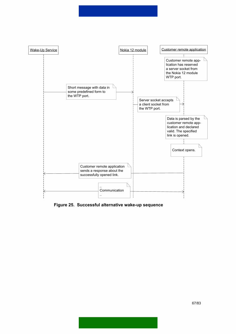
Wake-Up Service Nokia 12 module
Message1Short message with data insome predefined form tothe WTP port.
Message2Customer remote applicationsends a response about thesuccessfully opened link.
Customer remote application
Customer remote app-lication has reserveda server socket fromthe Nokia 12 moduleWTP port.
Data is parsed by thecustomer remote app-lication and declaredvalid. The specifiedlink is opened.
Message3Server socket acceptsa client socket fromthe WTP port.
Context opens.
..Communication..
Figure 25. Successful alternative wake-up sequence
67/83

Wake-Up Service Nokia 12 module
Message1Short message with invaliddata, sent to the WTP port.
Customer remote application
Customer remote app-lication has reserveda server socket fromthe Nokia 12 moduleWTP port.
Message2Server socket acceptsa client socket fromthe WTP port.
Data is parsed by thecustomer remote app-lication and declaredinvalid, and thusignored.
Figure 26. Unsuccessful alternative wake-up sequence
6.2.6 Sending the wake-up short message The wake-up short message can be sent the same way as a smart message (see Chapter 6.1.5.4).
6.3 NOKIA 12 GSM MODULE REMOTE CONFIGURATION The Module ORB of the Nokia 12 module has a CORBA interface that makes it possible to modify the connection parameters. The connection parameters, which can also be configured with the Configurator software for the Nokia 12 module, can be modified either from an IMlet or over-the-air from a customer server application.
You can get or set the connection parameters through the getParam or setParam method calls of the Device interface. The parameter structure used in those methods is WAPParameters, as described in the Nokia 12 GSM Module Properties Reference Guide. The setting of the connection parameters from an IMlet is described in detail in the Nokia 12 GSM Module JavaTM IMlet Programming Guide document.
6.4 JAVA IMLET REMOTE MANAGEMENT This chapter describes how to manage the Java IMlet applications of the Nokia 12 module remotely using the IMlet Suite Manager CORBA interface and IIOP.
68/83

Note: When IMlet Suites are downloaded to the Nokia 12 module using CORBA and IIOP, the J2ME ORB of the Nokia 12 module must be set to IIOP mode. The setting of the IIOP mode is described in detail in the Nokia 12 GSM Module JavaTM IMlet Programming Guide.
Note: Java IMlet applications can also be managed locally using the M2M System Protocol 2 via the COM2 of the Nokia 12 module.
6.4.1 Introduction The Nokia 12 module contains a CORBA object that makes it possible to download and manage IMlet Suites and IMlet applications in the Nokia 12 module.
With the IMlet Suite Manager CORBA interface software developers can:
• Download IMlet Suites to the Nokia 12 module.
• Browse on the IMlet Suites in the Nokia 12 module.
• Browse on the IMlet applications in the IMlet Suites.
• Start and stop IMlet applications in the Nokia 12 module.
• Listen to the events that IMlet applications generate in the Nokia 12 module.
• Remove IMlet Suites from the Nokia 12 module.
6.4.2 IMlet Suite Manager service This chapter describes the IMlet Suite Manager CORBA interface of the Nokia 12 module.
6.4.2.1 IMlet Suite Manager interface definition This chapter provides a definition of the IMlet Suite Manager CORBA interface. The methods introduced in this chapter are described in detail in Chapter 6.4.2.3.
module imletmanager { typedef sequence<octet> OctetArray; typedef sequence<string> StringArray; typedef long ListenerHandle; typedef long CallerID; // Runtime event types listen from IMlet typedef long RuntimeEventType;
69/83

const RuntimeEventType RT_ACTIVATED = 0x00000001; const RuntimeEventType RT_PAUSED = 0x00000002; const RuntimeEventType RT_STOPPED = 0x00000004; const RuntimeEventType RT_ALL_EVENTS = 0x0FFFFFFF; // Reasons for exceptions in IMlet loading process enum LoadExceptionReason { GENERAL_LOAD_EXCEPTION, LOAD_ERROR, INVALID_PACKET_SIZE }; enum SuiteManagerExceptionReason{ GENERAL_EXCEPTION, CORBA_EXCEPTION, MEMORY_ERROR, VALIDATION_ERROR, START_ERROR, STOP_ERROR, REMOVE_ERROR, PREPARE_ERROR, RUNTIME_ERROR, OUT_OF_MEMORY, NOT_FOUND, ALREADY_EXISTS, NOT_IMPLEMENTED }; // General Exception in IMlet Suite load exception LoadException { LoadExceptionReason reason; // More details about exception string description; }; // General SuiteManagerException exception SuiteManagerException { SuiteManagerExceptionReason reason; // More detail about exception string description; }; // IMlet application status enum IMletStatus { ERROR, ACTIVE, PAUSED, DESTROYED }; // Information about one IMlet Suite // This data is loaded in manifest file with IMlet Suite struct SuiteInformation{ string name; string imletVersion; string vendor; StringArray imletList; string microEditionProfile; string microEditionConfiguration; };
70/83

// Interface to listen runtime events from IMlet interface RuntimeListener{ // Event from terminal void runtimeEvent( in string sourceSuiteName, in string sourceIMletName, in CallerID callerID, in RuntimeEventType event, in string eventDescription ); }; // IMlet interface, represents one IMlet application in terminal interface IMlet{ // Starts IMlet. // If bForceStart flag is set // this IMlet overrides currently running IMlet void start(in boolean bForceStart) raises (SuiteManagerException); // Stops IMlet void stop() raises (SuiteManagerException); // Returns the IMlet state IMletStatus getStatus(); // Returns the IMlet name string getName(); // Returns the Suite name the IMlet belongs to string getSuiteName(); }; typedef sequence<IMlet> IMletArray; // IMlet Suite interface, Suite contains 1..n IMlets interface Suite { // Returns specified IMlet reference IMlet getIMlet(in string name) raises (SuiteManagerException); // Returns list of names of IMlets in this Suite StringArray getIMletNameList(); // Returns information of this IMlet Suite SuiteInformation getInformation(); }; // IMlet SuiteLoader interface that manages packet loading to terminal interface SuiteLoader { // Loads one packet of IMlet Suite void loadSuitePacket(in OctetArray data, in boolean isLastPacket) raises (LoadException); // Terminates the IMlet loading process // Note: This is not called when all packets are // sent successfully (with isLastPacket flag set) void terminateSuiteLoad() raises (LoadException); }; // SuiteManager Interface // Offers IMlet Suite services
71/83
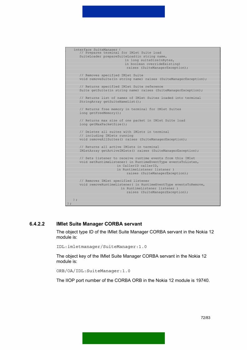
interface SuiteManager { // Prepares terminal for IMlet Suite load SuiteLoader prepareSuiteLoad(in string name, in long suiteSizeInBytes, in boolean overrideExisting) raises (SuiteManagerException); // Removes specified IMlet Suite void removeSuite(in string name) raises (SuiteManagerException); // Returns specified IMlet Suite reference Suite getSuite(in string name) raises (SuiteManagerException); // Returns list of names of IMlet Suites loaded into terminal StringArray getSuiteNameList(); // Returns free memory in terminal for IMlet Suites long getFreeMemory(); // Returns max size of one packet in IMlet Suite load long getMaxPacketSize(); // Deletes all suites with IMlets in terminal // including IMlets running void removeAllSuites() raises (SuiteManagerException); // Returns all active IMlets in terminal IMletArray getActiveIMlets() raises (SuiteManagerException); // Sets listener to receive runtime events from this IMlet void setRuntimeListener( in RuntimeEventType eventsToListen, in CallerID callerID, in RuntimeListener listener ) raises (SuiteManagerException); // Removes IMlet specified listener void removeRuntimeListener( in RuntimeEventType eventsToRemove, in RuntimeListener listener ) raises (SuiteManagerException); }; };
6.4.2.2 IMlet Suite Manager CORBA servant The object type ID of the IMlet Suite Manager CORBA servant in the Nokia 12 module is:
IDL:imletmanager/SuiteManager:1.0
The object key of the IMlet Suite Manager CORBA servant in the Nokia 12 module is:
ORB/OA/IDL:SuiteManager:1.0
The IIOP port number of the CORBA ORB in the Nokia 12 module is 19740.
72/83

6.4.2.3 IMlet Suite Manager interface methods This chapter introduces the methods of the IMlet Suite Manager CORBA interface.
The IMlet Suite Manager service contains the following five interfaces:
• SuiteManager
• SuiteLoader
• Suite
• IMlet
• RuntimeListener
The SuiteManager interface offers services for IMlet Suite managing and download initiation.
Table 26. SuiteManager interface methods
Method Description
getFreeMemory() Returns the free memory capacity of the IMlet Suites in a Nokia 12 module.
getMaxPacketSize() Returns the maximum IMlet Suite JAR data packet size that can be used for downloading.
getSuite(string name) Returns the Suite object with a given name.
getSuiteNameList() Returns a list of IMlet Suite names in a Nokia 12 module.
prepareSuiteLoad( string name, long suiteSize, boolean overrideExisting)
Prepares the Nokia 12 module for downloading one IMlet Suite. The needed parameters are the name of the IMlet Suite, the total size of the IMlet Suite JAR data packet and a flag that indicates whether an existing IMlet Suite is overwritten.
Returns a SuiteLoader object that is used to load IMlet Suite data to the Nokia 12 module.
removeAllSuites() Removes all IMlet Suites from a Nokia 12 module.
Note! The removeAllSuites() method also removes the IMlet Suites that include active IMlet applications.
removeSuite(string name) Removes one IMlet Suite with a given name.
Note! The removeSuite(string name)method removes the specified IMlet Suite even if it has active IMlet applications.
73/83

Method Description
getActiveIMlets() Returns an array of active IMlets of a given Nokia 12 module.
Note! The Nokia 12 module supports only one active IMlet at a time.
The SuiteLoader interface offers services to download IMlet Suite data and terminate the download process.
Table 27. SuiteLoader interface methods
Method Description
loadSuitePacket( OctetArray data boolean isLastPacket)
Loads one packet of the IMlet Suite JAR data into a Nokia 12 module. This method is called until all packets are downloaded to the Nokia 12 module. When the last data packet is downloaded, the isLastPacket parameter is set to ‘true’.
terminalSuiteLoad() This method terminates the IMlet Suite downloading process. The method is called if the client is unable to load all IMlet Suite data packets to the Nokia 12 module.
After calling this method the Nokia 12 module is ready to start a new IMlet Suite downloading process by calling the prepareSuiteLoad method of the SuiteManager object.
The Suite interface offers services to manage IMlet Suites in the Nokia 12 module. The Suite object reference can be received using the getSuite(string) method in the SuiteManager object.
Table 28. Suite interface methods
Method Description
getIMlet(string name) Returns an IMlet with a given name from an IMlet Suite.
getIMletNameList() Returns a list of IMlet names in an IMlet Suite.
getInformation() Returns a SuiteInformation object that contains information on the specified IMlet Suite.
The Nokia 12 module contains an IMlet interface that has methods to manage one IMlet application in the Nokia 12 module. The IMlet object reference can be received using the getIMlet(string) method in the Suite object.
74/83

Table 29. IMlet interface methods
Method Description
getName() Returns the name of the IMlet.
start(boolean force) Starts the IMlet application. If the force flag is enabled, the IMlet is started even if another IMlet is already running.
stop() Stops the IMlet application.
getStatus() Returns the status of the IMlet. The status can be one of the following IMletStatus enumeration types: ERROR, ACTIVE, PAUSED or DESTROYED.
getSuiteName() Returns the name of the Suite the IMlet belongs to.
setRuntimeListener( long eventTypesToListen, RuntimeListener listener)
Sets the RuntimeListener object to listen events from the IMlet. The parameter eventTypesToListen is a bit combination of the RuntimeEventType: RT_ACTIVATED, RT_PAUSED, RT_STOPPED, RT_ALL_EVENTS.
removeRuntimeListener( RuntimeListener listener)
Removes the RuntimeListener from the IMlet.
The RuntimeListener interface offers services that an IMlet can use to send events to the user’s application. The RuntimeListener servant implementation is in the user’s application and the object reference is set to an IMlet in the Nokia 12 module.
Table 30. RuntimeListener interface methods
Method Description
runtimeEvent( string sourceSuiteName, string sourceIMletName, CallerID callerID, RuntimeEventType type, string eventDescription)
This method is called when a specified event occurs in an IMlet application to which a RuntimeListener is set. The CallerID specifies the IMlet application in question.
6.4.3 Downloading IMlet Suites into the Nokia 12 GSM module This chapter describes how to download IMlet Suites into the Nokia 12 module.
IMlet Suites are downloaded to the Nokia 12 module in JAR files. One IMlet Suite can contain multiple IMlet applications.
75/83

An IMlet Suite JAR file must also contain a manifest file that provides the information about the contents of the JAR file. The content of the manifest file is described in the Mobile Information Device Profile (JSR-37) Specification.
IMlet Suite JAR data is downloaded to the Nokia 12 module in one or more data packets. The Nokia 12 module defines the maximum size (4096 bytes) for one data packet. If the IMlet Suite JAR file is bigger than the maximum packet size, the JAR file must be split into multiple data packets.
Note: One Nokia 12 module can have only one ongoing IMlet Suite download procedure at a time.
An IMlet Suite downloading process includes the following steps:
Create a SuiteManager CORBA object reference to the Nokia 12 module.
Get the maximum IMlet Suite packet size by calling the getMaxPacketSize() method in the SuiteManager object.
Split the IMlet Suite JAR file data to suitable packets (if necessary).
Start the IMlet Suite downloading process by calling the prepareSuiteLoad() method in the SuiteManager object. The method returns the SuiteLoader object reference that is used to download the IMlet Suite data packets.
Download the IMlet Suite JAR data packets one at a time by calling the loadSuitePacket() method in the SuiteLoader object. While the last packet is sent, set the lastPacket flag to true.
Note: If the prepareSuiteLoad() method in the SuiteManager is called and the IMlet Suite downloading process must be cancelled before the last packet is sent, the terminateSuiteLoad() method in the SuiteLoader object must be called. If this is not done, a new IMlet Suite loading process cannot be started until the Nokia 12 module is rebooted.
76/83

Get the ImletSuiteManagerobject reference
Get maximum JAR packet sizefrom the ImletSuiteManager
Start loading one IMlet Suiteto the Nokia 12 module
Split JAR file intosmaller packets
IsJAR bigger than
max packetsize?
Yes
Prepare IMlet Suitedownloading
Haveall packets been
sent?
End IMlet Suitedownload
Yes
Is this thelast packet?
No
Set the last packetflag to ’true’
Yes
Load IMlet Suite JAR packet
No
Wherethere errors?
Yes
Terminate Suiteload
No
No
Figure 27. IMlet Suite download process
Figure 28 describes an IMlet Suite download sequence.
77/83

IMlet Suite loading SuiteManager SuiteLoader
1: getMaxPacketSize()
2: prepareSuiteLoad()
3: loadSuitePacket()
Call untilall packets
have been loaded
Figure 28. IMlet Suite download sequence
6.4.4 Managing IMlet Suites in the Nokia 12 GSM module With the IMlet Suite Manager CORBA interface a software developer can browse and manage IMlet Suites and IMlet applications in the Nokia 12 module.
6.4.4.1 Managing IMlet Suites A software developer can manage IMlet Suites in the Nokia 12 module by using the SuiteManager object. With the SuiteManager object a software developer can:
• Browse IMlet Suites:
− List all IMlet Suite names.
− List the IMlets of a specified IMlet Suite.
• Remove IMlet Suites:
• Remove all IMlet Suites from the Nokia 12 module.
• Remove specified IMlet Suites from the Nokia 12 module. IMlet Suites are indentified by the name that is initialized when the IMlet Suite loading process is started by the prepareSuiteLoad() method in the SuiteManager object.
78/83

6.4.4.2 Managing IMlet applications A software developer can manage IMlet applications in the Nokia 12 module by using the Suite object. With the Suite object a software developer can:
• Browse IMlet applications:
− List all IMlet applications in the Suite.
− Get IMlet object references by IMlet names.
• Start and stop IMlet applications. The IMlet applications in the Suite object are identified by their name that is initialised in the manifest file included in the IMlet Suite JAR file.
You can get the Suite object reference by using the getSuite(string) method in the SuiteManager object.
6.4.5 Runtime events A software developer can create a RuntimeListener object that is able to listen to events that occur in IMlet applications.
A runtime event is defined as a RuntimeEventType in the CORBA interface definition.
Table 31. Runtime event types
Event type Description
RT_ACTIVATED (0x00000001) This event is thrown when an IMlet is activated in the Nokia 12 module.
RT_PAUSED (0x00000002) This event is thrown when an IMlet is paused in the Nokia 12 module.
RT_STOPPED (0x00000004) This event is thrown when an IMlet is stopped in the Nokia 12 module.
RT_ALL_EVENTS (0x0FFFFFFF) This event type value sets all the above events active in the IMlet application.
Note! This event type is never fired.
The RuntimeListener object is set to the IMlet object using the setRuntimeListener() method. The same RuntimeListener object instance can be set to multiple IMlet objects in multiple Nokia 12 modules. The RuntimeListener object can listen to one or more event types at a time. The user can identify individual IMlets by setting a unique caller ID when setting the RuntimeListener object.
79/83

When the selected event occurs in an IMlet application, the IMlet calls the runtimeEvent() method in the RuntimeListener object that the user has initialised.
6.4.6 Example application This chapter introduces an IMlet Suite Management example application implemented in Java.
The application downloads one IMlet Suite to a Nokia 12 module. It checks whether the IMlet Suite already exists and asks confirmation from the user to override the existing IMlet Suite. It also activates the specified IMlet application in the IMlet Suite. If there already is an active IMlet in the target Nokia 12 module, the application asks confirmation from the user to stop the current IMlet, and to activate a new IMlet in the IMlet Suite.
Preliminary conditions:
• The Nokia 12 module ORB is in the IIOP mode.
• TCP/IP connection is open to the target Nokia 12 module and the target Nokia 12 module has a valid IP address.
Preliminary information:
• A Java IMlet application is implemented.
• An IMlet Suite containing the Java IMlet application is properly implemented.
• The IMlet Suite Manager CORBA stubs are properly compiled from the IMlet Suite Manager interface definition using a Java IDL compiler.
public class IMletSuiteLoader { public static void main(String[] args) { try { String sIMletSuiteFilename = ""; String sIMletSuiteName = ""; String sIMletName = ""; String sNokia12IpAddress = ""; // Read the start parameters if(args.length>3) { sNokia12IpAddress = args[0]; sIMletSuiteName = args[1]; sIMletSuiteFilename = args[2]; sIMletName = args[3]; } else { throw new Exception("Not enough parameters"); }
80/83

byte[] jarData = null; // ... Read the data from file ... System.out.println("Downloading IMlet Suite..."); IMletSuiteLoader loader = new IMletSuiteLoader(); loader.loadIMletSuite(sNokia12IpAddress, sIMletSuiteName, jarData, sIMletName); System.out.println("IMlet Suite successfully downloaded"); } catch(Exception e) { System.out.println("Error in application: " + e.toString()); } } /** * Downloads IMlet Suite JAR data to Nokia 12 module. * <br> * If the parameter sIMletApplicationName is set empty no IMlet is started * in the Nokia 12 module * @param sModuleIp IP address of the target Nokia 12 module * @param sSuiteName Name of the IMlet Suite * @param imletSuiteData IMlet Suite JAR file data * @param sIMletApplicationName Name of the IMlet to be started * in the Nokia 12 module * @throws Exception */ public void loadIMletSuite(String sModuleIp, String sSuiteName, byte[] imletSuiteData, String sIMletApplicationName) throws Exception { // Initialize CORBA ORB ORB orb = ORB.init(new String[]{},System.getProperties()); // IMlet Suite Manager object key in Nokia 12 module String sObjectKey = "ORB/OA/IDL:SuiteManager:1.0"; // IMlet Suite Manager corbaloc object url String sCorbaloc = "corbaloc::" + sModuleIp + ":19740/" + sObjectKey; // Create reference to IMlet Suite Manager object org.omg.CORBA.Object corbaObject = orb.string_to_object(sCorbaloc); SuiteManager suiteManager = SuiteManagerHelper.narrow(corbaObject); // // Check the current IMlet Suite information in the Nokia 12 // // Check if enough memory for current IMlet Suite // The free memory returned is in kilobytes int iFreeMemory = suiteManager.getFreeMemory() * 1024; if(iFreeMemory<imletSuiteData.length) { throw new Exception("Not enough memory for IMlet Suite"); } // Check if current IMlet Suite exists boolean bSuiteExists = false; try { Suite suite = suiteManager.getSuite(sSuiteName); bSuiteExists = true; // There is already a Suite with same name } catch(SuiteManagerException e) { if(e.reason!=SuiteManagerExceptionReason.NOT_FOUND) { throw new Exception("Error while getting IMlet Suite: " + e.description); } }
81/83

if(bSuiteExists) { // Ask from user to override if ( !confirmFromUser("Override existing suite?" ) ) { throw new Exception("IMlet Suite Loading cancelled"); } } // Start the IMlet Suite loading // Get maximum packet size (returns bytes) int iMaxPacketSize = suiteManager.getMaxPacketSize(); SuiteLoader suiteLoader = null; try { // Get the IMlet Suite loader object // Force flag is set to true because user has // previously confirmed Suite override suiteLoader = suiteManager.prepareSuiteLoad(sSuiteName, imletSuiteData.length, true); // Load the IMlet Suite data packets boolean bLastPacket = false; int iCurrentIndex = 0; int iPacketLength = 0; byte[] bbPacket = null; while(!bLastPacket) { iPacketLength = imletSuiteData.length - iCurrentIndex; if(iPacketLength>iMaxPacketSize) { iPacketLength = iMaxPacketSize; } // Create one data packet for loading bbPacket = new byte[iPacketLength]; System.arraycopy( imletSuiteData, iCurrentIndex, bbPacket, 0, iPacketLength ); iCurrentIndex += iPacketLength; bLastPacket = ( iCurrentIndex>=imletSuiteData.length ); // Load the data packet to the Nokia 12 module suiteLoader.loadSuitePacket(bbPacket,bLastPacket); } } catch(Exception e) { // Error occurred during download process if(suiteLoader!=null) { // We must terminate loading suiteLoader.terminateSuiteLoad(); } throw new Exception("IMlet Suite download failed: " + e.toString()); } if(sIMletApplicationName!=null && !sIMletApplicationName.equals("")) { // Activate the specified Java IMlet application // from the suite just downloaded try { // First check if any IMlet already active IMlet[] imletArray = suiteManager.getActiveIMlets(); if(imletArray.length>0) { if(!confirmFromUser( "There is IMlet already active. Override that?") ) { throw new Exception( "IMlet application activation cancelled");
82/83

} } } catch(SuiteManagerException e) { System.out.println("Error while checking Active IMlets: " + e.reason.value() + ":" + e.description); } Suite suite = suiteManager.getSuite(sSuiteName); IMlet imlet = suite.getIMlet(sIMletApplicationName); // Activate IMlet. Force flag is set to true. imlet.start(true); } // IMlet Suite download completed. } private boolean confirmFromUser(String sConfirmMessage) { boolean bOk = false; System.out.println(sConfirmMessage + " [y/n]"); try { // Read answer byte byteAnswer = (byte)System.in.read(); bOk = (byteAnswer==0x59 || byteAnswer==0x79); while (System.in.available()>0 || byteAnswer != 10) { byteAnswer = (byte)System.in.read(); } } catch(IOException ignore){} return bOk; } }
83/83