ux tubo - minuszerodegrees.net - ux turbo mainboard... · on f colo rg ap ics adapter (80x25) off...
TRANSCRIPT

UX Tubo(44256 VERSION)

CONTENTS1.
2.3.
4.
Introduction
Featuresof, UX Turbo mainboard
System Configuration
5.1 System Configuration 0 IP Switches5.2 Switch Settings and Connector Descriptions
Wait State
Software Utility
5.
Appendix A
Appendix B
Appendix C
Appendix D
Appendix E
Appendix G
1-1
2-1
3-1
4-1
5-1
5-15-3
Summary of Connectors A-l
8-1Wait State Programming
RAM Chip Configuration C-l
Error Messageof AWARD BIOS 0-1
General Information on Trouble-Shooting E-l
Dimension of UX Turbo mainboard F-l
Layout of UX Turbo mainboard G-l
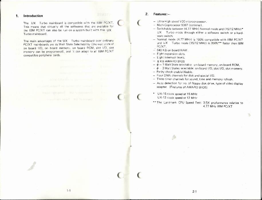
2. Features:--1. Introduction
The UX Turbo mainboard is compatible with the IBM PC/XT.This means that virtually all the softwares that are available forthe IBM PC/XT can also be run on a system built with this UXTurbo mainboard.
UItra-H igh speed V20 microprocessor.Math-Coprccessor 8087 (optional).Switchable between (4.77 MHz) Normal mode and (15/12 MHz)*UX Turbo mode through either a software switch or a hard-ware switch.Normal mode (4.77 MHz) is 100% compatible with IBM PC/XTand UX Turbo mode (15/12 MHz) is 350%** faster than IBMPC/XT.640 KB on board RAM.Eight expansion slots.Eight interrupt levels.8 KB AWARD BIOS
rp - 1 Wait State selectable 0 n board memory, on board ROM.rp - 3 Wait States selectable: on board I/O, slot I/O, slot rnornerv.Parity check enable/disable.Four DMA channels for disk and special I/O.Three timer channels for sound, time and memory refresh.Auto detection for no. of floppy disk drive, type of video displayadapter (Features of AWARD BIOS)
The main advantages of the UX Turbo mainboard over ordinaryPC/XT mainboards are its Wait State Selectability (the wait state ofon board I/O, on board memory, on board ROM, slot I/O, slotmemory can be programmed), and it can adapt to all IBM PC/XTcompatible peripheral cards.
UX·15 clock speed at 15 MHzUX-12 clock speed at 12 MHz
•• The Landmark CPU Speed Test: 3.5X proformance relative to4.77 MHz IBM PC/XT
I,
1-1 2-1

3. Wait State
The factory default settings for wait state are as follows: (
On board RAM access 0 wait state
On board ROM access , wait state
On board I/O access , wait state
On slot RAM access 3 wait states
On slot I/O access 3 wait states
As expansion RAM access is treated as 'slot RAM access', 3 waitstates are inserted on each access of the expansion RAM card onslot. This is for safe-quardinq to accommodate the slowest I/Odevices on the system (slot).
However, we provide option of software programming to vary thewait states. For the software programming, pleaserefer to appendixB.
Hardware Option:-
The hardware switch is located at J6** jumper on the mainboard. Onboard RAM is set to one wait state since the J6 jumper is shorted.when J6 jumper is open, it is in Zero Wait State.
J6
Open * o Wait State (On board RAM)
Close , Wait State (On board RAM)
* Default setting.** Location of jumper J6, please refer to Appendix G.
3·'
. .
4. Software Utility
Switching between UX Turbo and Normal mode can bedone by hardware or software. Hardware configuration willbe mentioned in Section 5.2 (h). The procedures to set up thesoftware switch are as follows:
(i) Insert Utility Diskette in Drive A, type 'Turbo' thenpress return key. After the program TURBO.COM isbeing executed, the UX Turbo mode selection canbe done by software.
(ii) Turn UX Turbo mode on, simply press 'Ctl', 'All'and '+' simultaneously.
(iii) Turn UX Turbo mode off, simply press 'Ctl'. 'All'and r.:: simultaneously.
(iv) Return to Hardware selection, press 'Ctl'. 'Alt' and '*'
simultaneously.
In the other way, it also can be used asa functional command,such as:-
A: TURBO (SWITCH)Where (SWITCH) ~ ON: UX Turbo mode is selected.
OFF: Normal mode is selected.HARD: Return to Hardware selection.
Note:The hardware switch can not affect the system speed whilethe system under software control, but not vise versa.
4·'

5. System Configuration
This section provides information for preparing the UX Turbo I
mainboard to use. The user should understand all the Informationcontained in this section before beginning to configure the system.
5.1 System Configuration DIP Switches (SWA)
The UX Turbo mainboard has an eight way DIP switches to set thesystem configuration. The switch settings are listed as followings:-
SWA - System Configuration DIP Switches
ON
BBBBBBBB2 3 4 5 6 7 8OFF
SW1 - Parity Check Optionsvn - Must be ON (Reserved for Maths Co-Processor)SW3, SW4 - Amount of Memory on System BoardSW5, SW6 - Tvpels) of Display Adapter(s)SW7, SW8 - Number of 5% inch Diskette Drivers Installed
SW1,SW2
Switch Function
On Disable Parity Check (DRAM)
SW1 Off Enable Parity Check (DRAM)
On Reserved (Must be On)
SW2 Off Unused
Note: Parity RAM chip(s) is required to insert to Parity Chipsocketts) if Parity Check is enabled.
fi-l
SW3, SW4
SW3 SW4 Memory Size
On On </>K
Off On 512 K
On Off 640 K
Off Off 1 M
SW5, SW6
SW5 SW6 Display Adapter
On On No Display Adapter
Off On Color Graphics Adapter (40x25)
On Off Color Graphics Adapter (80x25)
Off Off Monochrome Display Adapter
SW7, SW8
SW7 SW8 Diskette Drives--
On On 1 Drive
Off On 2 Drives
On Off 3 Drives
Off Off 4 Drives
5-2

5.2 Switch Settings and Connector Descriptions
The UX Turbo mainboard provides the following connectors foryour control pannel. keyboard and power supply:
Keyboard connectorPower supply connectorPower lightReset switchSpeaker connectorKeylockTurbo lightTurbo switch
The location of the above connectors is shown below:-
CN1.
CN8 TURBO SWITCH
CN7 TURBO LIGHT
CN6 KEY LOCKCN4 RESET SWITCH
CN3 POWER LIGHT
5-3
CN2. POWERSUPPLY
CONNECTOR
PAR8087MEMMEMOISPOISPFOOFOO
SW-ASYSTEMCONFIGURAT·IONDIPSWITCHES
']
a) Keyboard Connector (CN1)
The keyboard connector is located at CN 1. the pin out of CN 1are as follows:
5-Pin D IN Connector
Pin Descr iption
1 Keyboard Clock2 Keyboard Data.3 Spare4 Keyboard Ground5 +5V DC
b) Power Supply Connector (CN2)
Power supply connector CN2 is a single plastic connector.The pin assigments for the power supply connector are asfollows:
Pin Description
1 Power Good2 +5V DC3 +12V DC4 -12V DC5 Ground6 Ground7 Ground8 Ground9 -5V DC
10 +5V DC11 +5V DC12 +5V DC
5-4

c) Power Light (CN3)
The power light connector is located at CN3. If the LED isconnected to CN3, it will be on while the power is switchedon. The pinout description is shown below
~CN3
2 +
Pin Description
1 - Cathode2 + Anode
d) Reset Switch (CN4)
With a switch connected to CN4, the computer will operatenormally while the switch is open. If you press and releasethe switch once, it will cause the system to reset. The switchsetting and pinout are as follows:
~CN4
1 2 +
CN4 Function
Open ExecutingClose Reset CPU
Pin Description
1 Ground2 Reset In
Warning: If the reset button is pressed accidentally to terminate anyprocess, the data will be lost.
5-5
e) Speaker Connector (CN5)
To use the speaker function, connecting a speaker to CN5 onthe mainboard. The pinout assigment is shown belows
]gCN5
1 2 +
Pin Description
Speaker Data Out+5V DC
12
f) Keylock (CN6)
The key lock connector is located at CN6 on the mainboard.The keyboard is locked while the CN6 is shorted. When theCN6 is open, the keyboard is unlocked. For the switch settingsand pinout of keylock connector, refer to the following table:
@:::§] CN6
1 2 +
(.1
\
CN6 Function
Open Enable Key BoardClose Lock Key Board
Pin Description
1 Ground2 Key In
5-6

5-7 A-1
g) Turbo Lighr (eN7)
The Turbo LED indicates operation in UX Turbo mode. TheTurbo Light Connector is located at CN7 on the mainboard.The pinouts for the connector at CN7 are as follows:
Appendix A Summary of Connectors
~CN7
1 2 +
..•~ Connector Pin Out Function
Keyboard CNl 1 Keyboard Clock2 Keyboard Data3 Spare N/A4 Keyboard Ground5 +5V DC
Power Supply CN2 1 Power Good
2 +5VOC3 +12V DC4 -12V DC5 Ground6 Ground N/A7 Ground8 Ground9 -5VDC10 +5V DC11 +5V DC12 +5VOC
Power Light CN3 1 - CathodeN/A
2 + Arode
Reset Switch CN4 1 Ground Open Executing2 Reset In Close Reset CPU
Speaker Connector CN5 1 Speaker Data OutN/A2 +5V DC
Keylock CN6 1 Ground Open Enable Keyboard...• 2 Key In Close Disable Keyboard
Turbo Light CN7 1 - CathodeN/A2 + Anode
Turbo Switch CNS 1 Turbo In Open Normal Speed2 +5VDC Close Super Turbo Speed
Wait State Switch J6 1 Wait State In Open o Wait State (On board RAM)
2 Ground Close 1 Wait State (On board RAM)
Pin Description
1 - Cathode2 + Anode
h) Turbo Switch (eN8)
The operation of the system can be switched between UX·Turbo and Normal mode. The connector of the switch islocated at CNS on the mainboard. The UX Turbo modeis on while the CNS jumper is shorted. When the jumper isopen, the system is in Normal mode. The pinout assigmentand switch setting of Turbo Switch is show below:
~CNS
1 2 +
CNS CPU Speed
Open 4.77 MHzClose 15/12 MHz*
CNS. Turbo Switch
Pin Description
1 Turbo In2 +5V DC
* Unquie UX-15 clock speed at 15 MHzUnquie UX-12 clock speed at 12 MHz
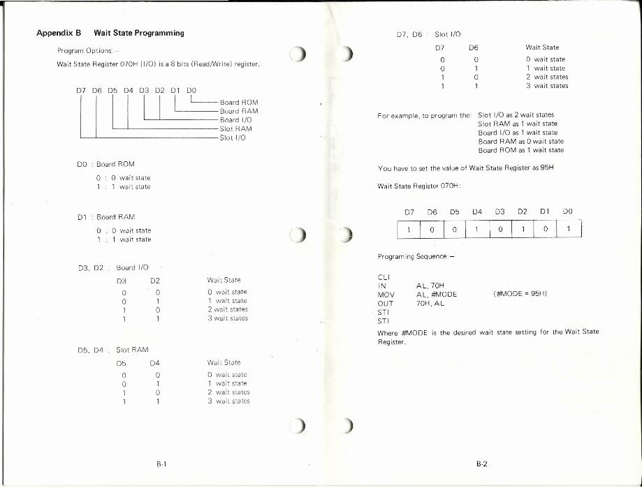
01 Board RAM
0 o wait state1 1 wait state
03, 02 Board I/O
03 02
0 00 11 01 1
05,04 Slot RAM
05 04
0 00 11 01 1
07 06 05 04 03 02 01 DO
Appendix B Wait State Programming
°u7
06 ou5
04 ou3
02 1<-1_,0 __ Board ROMBoard RAM
'------- Board I/OSlot RAMSlot I/O
07, 06 Slot I/O
07 06 Wait State
0 0 o wait state0 1 1 wait state1 0 2 wait states1 1 3 wait states
Program Options:-
Wait State Register 070H (I/O) is a 8 bits (Read/Write) register.
For example, to program the: Slot I/O as 2 wait statesSlot RAM as 1 wait stateBoard I/O as 1 wait stateBoard RAM as 0 wait stateBoard ROM as 1 wait state
DO : Board ROM You have to set the value of Wait State Register as 95Ho 0 wait state1 1 wa it state Wait State Register 070H:
Program ing Sequence:-
Wait State
o wait state1 wait state2 wa it states3 wait states
CLIINMOVOUTSTISTI
AL,70HAL, #MODE70H, AL
(#fIt100E = 95H)
Where #MODE is the desired wait state setting for the Wait StateRegister.
Wait State
o wait state1 wait state2 wa it stales3 wait states
B-1 B-2
r---------------------------------------------------------------------------------------------------------------------------------
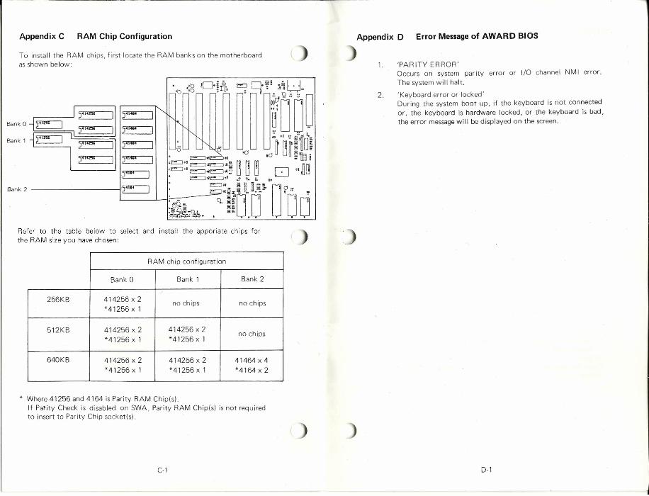
Appendix C RAM Chip Configuration
To install the RAM chips, first locate the RAM banks on the motherboardasshown below:
Refer to the table below to select and install the apporiate chips forthe RAM size you have chosen:
RAM chip configuration
Bank 0 Bank 1 Bank 2
256KB 414256 x 2 no chips no chips*41256x 1
512KB 414256 x 2 414256 x 2 no chips*41256 xl *41256 xl
640KB 414256 x 2 414256 x 2 41464 x 4*41256x 1 *41256 x 1 *4164 x 2
* Where 41256 and 4164 is Parity RAM Chip(s).If Parity Check is disabled on SWA, Parity RAM Chlpls) is not requiredto insert to Parity Chip socketts).
C-l
Appendix D Error Messageof AWARD BIOS
1. 'PARITY ERROR'Occurs on system parity error or I/O channel NMI error.The system will halt.
'Keyboard error or locked'During the system boot up, if the keyboard is not connectedor, the keyboard is hardware locked, or the keyboard is bad,the error messagewill be displayed on the screen.
2.
0-1
Appendix E General Information on Trouble-Shooting. 4. Video display and UX Turbo mainboard work property, but theKeyboard is malfunction.Problem.a) Keylock is locked.Solution:Unlocked the key lock.Problem:b) Keyboard is not connected to the UX Turbo mainboard.Solution:Connect the Keyboard Connector Properly.
Symptoms1. No video display and no power light during the power up.
Problem:a) Power Cord is not connected.SolutionCheck power cord is properly installed.Problem:b) Power supply does not work.Solution:Replaceanother power supply.
2. No video display and 1 beep is heard, but the floppy disk doeswork.Problem:a) Video plug is not connected.Solution:Connect the video plug to display adapter.Problem.b) Switch settings of the system configuration on the UX Turbo
mainboard is not correct.Solution:Check the system configuration and change it to correct setting.
3. 1 long 2 short beeps are heard with no video display, but the floppydisk drive doeswork.Problem:a) Switch settings of display mode on the display card is not correct.Solution:Check the switch settings of the display card, and set it to correctsetting.Problem:b) Some dirt or bad contact between the card-edge signal tabs of the
display card and the I/O slots.Solution:Clean the card-edgesignal tabs with contact cleaner or insert the displayadapter to anther slot on the UX Turbo mainboard.
E-1 E-2
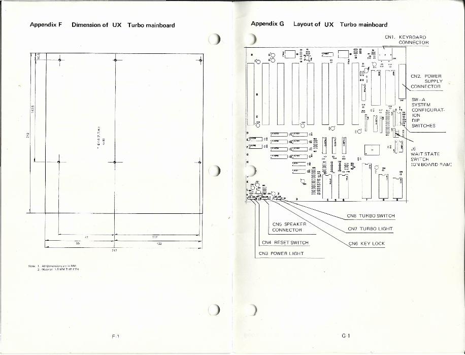
Appendix F Dimension of UX Turbo mainboard Appendix G
CN1. KEYBOARDCONNECTOR
Layout of UX Turbo mainboard
'" -+ -+rL t-
'"~
N
"'
--< r-- -<
77 117
95 122
'0 '0~;!!~*g
.E::::J*S ~;fl~;lIg,E::::J*2 ~#l~;ll~
• ~#I~*i
J6WAIT STATESWITCH(ON BOARD RAM)
CN5 SPEAKERCONNECTOR
CN8 TURBO SWITCH
CN7 TURBO LIGHT
Note 1. All Dimensions are in MM2. Material 1.6 MM THR F R4
CN3 POWER LIGHT
CN4 RESET SWITCH
F-l
CN6 KEY LOCK
G-l