uwb signal and i/q modulation generator · disposal/environmental protection", item 2....
TRANSCRIPT

1410.9052.62-03- 1
Quick Start Guide
UWB Signal and I/Q Modulation Generator
R&SAFQ100B 1410.9000K02
Test and Measurement Division
1410.9052.62-03- 2
This document describes the R&S®AFQ100B, stock no. 1410.9000K02 and its options. ©2017 Rohde & Schwarz GmbH & Co. KG Mühldorfstr. 15, 81671 München, Germany Phone: +49 89 41 29 - 0 Fax: +49 89 41 29 12 164 Email: [email protected] Internet: http://www.rohde-schwarz.com/ Subject to change – Data without tolerance limits is not binding. R&S® is a registered trademark of Rohde & Schwarz GmbH & Co. KG. Trade names are trademarks of the owners. The following abbreviations are used throughout this manual: R&S®AFQ100B is abbreviated as R&S AFQ.

1171.0000.42 - 09 Page 1
Basic Safety Instructions
Always read through and comply with the following safety instructions!
All plants and locations of the Rohde & Schwarz group of companies make every effort to keep the safety standards of our products up to date and to offer our customers the highest possible degree of safety. Our products and the auxiliary equipment they require are designed, built and tested in accordance with the safety standards that apply in each case. Compliance with these standards is continuously monitored by our quality assurance system. The product described here has been designed, built and tested in accordance with the EC Certificate of Conformity and has left the manufacturer’s plant in a condition fully
complying with safety standards. To maintain this condition and to ensure safe operation, you must observe all instructions and warnings provided in this manual. If you have any questions regarding these safety instructions, the Rohde & Schwarz group of companies will be happy to answer them.
Furthermore, it is your responsibility to use the product in an appropriate manner. This product is designed for use solely in industrial and laboratory environments or, if expressly permitted, also in the field and must not be used in any way that may cause personal injury or property damage. You are responsible if the product is used for any purpose other than its designated purpose or in disregard of the manufacturer's instructions. The manufacturer shall assume no responsibility for such use of the product.
The product is used for its designated purpose if it is used in accordance with its product documentation and within its performance limits (see data sheet, documentation, the following safety instructions). Using the product requires technical skills and, in some cases, a basic knowledge of English. It is therefore essential that only skilled and specialized staff or thoroughly trained personnel with the required skills be allowed to use the product. If personal safety gear is required for using Rohde & Schwarz products, this will be indicated at the appropriate place in the product documentation. Keep the basic safety instructions and the product documentation in a safe place and pass them on to the subsequent users.
Observing the safety instructions will help prevent personal injury or damage of any kind caused by dangerous situations. Therefore, carefully read through and adhere to the following safety instructions before and when using the product. It is also absolutely essential to observe the additional safety instructions on personal safety, for example, that appear in relevant parts of the product documentation. In these safety instructions, the word "product" refers to all merchandise sold and distributed by the Rohde & Schwarz group of companies, including instruments, systems and all accessories. For product-specific information, see the data sheet and the product documentation.
Safety labels on products
The following safety labels are used on products to warn against risks and dangers.
Symbol Meaning Symbol Meaning
Notice, general danger location
Observe product documentation ON/OFF Power
Caution when handling heavy equipment
Standby indication
Danger of electric shock Direct current (DC)

Basic Safety Instructions
1171.0000.42 - 09 Page 2
Symbol Meaning Symbol Meaning
Caution ! Hot surface Alternating current (AC)
Protective conductor terminal To identify any terminal which is intended for connection to an external conductor for protection against electric shock in case of a fault, or the terminal of a protective earth
Direct/alternating current (DC/AC)
Earth (Ground)
Class II Equipment to identify equipment meeting the safety requirements specified for Class II equipment (device protected by double or reinforced insulation)
Frame or chassis Ground terminal
EU labeling for batteries and accumulators
For additional information, see section "Waste disposal/Environmental protection", item 1.
Be careful when handling electrostatic sensitive devices
EU labeling for separate collection of electrical and electronic devices
For additional information, see section "Waste disposal/Environmental protection", item 2.
Warning! Laser radiation
For additional information, see section "Operation", item 7.
Signal words and their meaning
The following signal words are used in the product documentation in order to warn the reader about risks and dangers.
Indicates a hazardous situation which, if not avoided, will result in death or serious injury.
Indicates a hazardous situation which, if not avoided, could result in death or serious injury.
Indicates a hazardous situation which, if not avoided, could result in minor or moderate injury.
Indicates information considered important, but not hazard-related, e.g. messages relating to property damage. In the product documentation, the word ATTENTION is used synonymously.
These signal words are in accordance with the standard definition for civil applications in the European Economic Area. Definitions that deviate from the standard definition may also exist in other economic areas or military applications. It is therefore essential to make sure that the signal words described here are always used only in connection with the related product documentation and the related product. The use of signal words in connection with unrelated products or documentation can result in misinterpretation and in personal injury or material damage.
Basic Safety Instructions
1171.0000.42 - 09 Page 3
Operating states and operating positions
The product may be operated only under the operating conditions and in the positions specified by the
manufacturer, without the product's ventilation being obstructed. If the manufacturer's specifications are
not observed, this can result in electric shock, fire and/or serious personal injury or death. Applicable local
or national safety regulations and rules for the prevention of accidents must be observed in all work
performed.
1. Unless otherwise specified, the following requirements apply to Rohde & Schwarz products: predefined operating position is always with the housing floor facing down, IP protection 2X, use only indoors, max. operating altitude 2000 m above sea level, max. transport altitude 4500 m above sea level. A tolerance of ±10 % shall apply to the nominal voltage and ±5 % to the nominal frequency, overvoltage category 2, pollution degree 2.
2. Do not place the product on surfaces, vehicles, cabinets or tables that for reasons of weight or stability are unsuitable for this purpose. Always follow the manufacturer's installation instructions when installing the product and fastening it to objects or structures (e.g. walls and shelves). An installation that is not carried out as described in the product documentation could result in personal injury or even death.
3. Do not place the product on heat-generating devices such as radiators or fan heaters. The ambient temperature must not exceed the maximum temperature specified in the product documentation or in the data sheet. Product overheating can cause electric shock, fire and/or serious personal injury or even death.
Electrical safety
If the information on electrical safety is not observed either at all or to the extent necessary, electric shock,
fire and/or serious personal injury or death may occur.
1. Prior to switching on the product, always ensure that the nominal voltage setting on the product matches the nominal voltage of the mains-supply network. If a different voltage is to be set, the power fuse of the product may have to be changed accordingly.
2. In the case of products of safety class I with movable power cord and connector, operation is permitted only on sockets with a protective conductor contact and protective conductor.
3. Intentionally breaking the protective conductor either in the feed line or in the product itself is not permitted. Doing so can result in the danger of an electric shock from the product. If extension cords or connector strips are implemented, they must be checked on a regular basis to ensure that they are safe to use.
4. If there is no power switch for disconnecting the product from the mains, or if the power switch is not suitable for this purpose, use the plug of the connecting cable to disconnect the product from the mains. In such cases, always ensure that the power plug is easily reachable and accessible at all times. For example, if the power plug is the disconnecting device, the length of the connecting cable must not exceed 3 m. Functional or electronic switches are not suitable for providing disconnection from the AC supply network. If products without power switches are integrated into racks or systems, the disconnecting device must be provided at the system level.
5. Never use the product if the power cable is damaged. Check the power cables on a regular basis to ensure that they are in proper operating condition. By taking appropriate safety measures and carefully laying the power cable, ensure that the cable cannot be damaged and that no one can be hurt by, for example, tripping over the cable or suffering an electric shock.

Basic Safety Instructions
1171.0000.42 - 09 Page 4
6. The product may be operated only from TN/TT supply networks fuse-protected with max. 16 A (higher fuse only after consulting with the Rohde & Schwarz group of companies).
7. Do not insert the plug into sockets that are dusty or dirty. Insert the plug firmly and all the way into the socket provided for this purpose. Otherwise, sparks that result in fire and/or injuries may occur.
8. Do not overload any sockets, extension cords or connector strips; doing so can cause fire or electric shocks.
9. For measurements in circuits with voltages Vrms > 30 V, suitable measures (e.g. appropriate measuring equipment, fuse protection, current limiting, electrical separation, insulation) should be taken to avoid any hazards.
10. Ensure that the connections with information technology equipment, e.g. PCs or other industrial computers, comply with the IEC 60950-1 / EN 60950-1 or IEC 61010-1 / EN 61010-1 standards that apply in each case.
11. Unless expressly permitted, never remove the cover or any part of the housing while the product is in operation. Doing so will expose circuits and components and can lead to injuries, fire or damage to the product.
12. If a product is to be permanently installed, the connection between the protective conductor terminal on site and the product's protective conductor must be made first before any other connection is made. The product may be installed and connected only by a licensed electrician.
13. For permanently installed equipment without built-in fuses, circuit breakers or similar protective devices, the supply circuit must be fuse-protected in such a way that anyone who has access to the product, as well as the product itself, is adequately protected from injury or damage.
14. Use suitable overvoltage protection to ensure that no overvoltage (such as that caused by a bolt of lightning) can reach the product. Otherwise, the person operating the product will be exposed to the danger of an electric shock.
15. Any object that is not designed to be placed in the openings of the housing must not be used for this purpose. Doing so can cause short circuits inside the product and/or electric shocks, fire or injuries.
16. Unless specified otherwise, products are not liquid-proof (see also section "Operating states and operating positions", item 1). Therefore, the equipment must be protected against penetration by liquids. If the necessary precautions are not taken, the user may suffer electric shock or the product itself may be damaged, which can also lead to personal injury.
17. Never use the product under conditions in which condensation has formed or can form in or on the product, e.g. if the product has been moved from a cold to a warm environment. Penetration by water increases the risk of electric shock.
18. Prior to cleaning the product, disconnect it completely from the power supply (e.g. AC supply network or battery). Use a soft, non-linting cloth to clean the product. Never use chemical cleaning agents such as alcohol, acetone or diluents for cellulose lacquers.
Operation
1. Operating the products requires special training and intense concentration. Make sure that persons who use the products are physically, mentally and emotionally fit enough to do so; otherwise, injuries or material damage may occur. It is the responsibility of the employer/operator to select suitable personnel for operating the products.

Basic Safety Instructions
1171.0000.42 - 09 Page 5
2. Before you move or transport the product, read and observe the section titled "Transport".
3. As with all industrially manufactured goods, the use of substances that induce an allergic reaction (allergens) such as nickel cannot be generally excluded. If you develop an allergic reaction (such as a skin rash, frequent sneezing, red eyes or respiratory difficulties) when using a Rohde & Schwarz product, consult a physician immediately to determine the cause and to prevent health problems or stress.
4. Before you start processing the product mechanically and/or thermally, or before you take it apart, be sure to read and pay special attention to the section titled "Waste disposal/Environmental protection", item 1.
5. Depending on the function, certain products such as RF radio equipment can produce an elevated level of electromagnetic radiation. Considering that unborn babies require increased protection, pregnant women must be protected by appropriate measures. Persons with pacemakers may also be exposed to risks from electromagnetic radiation. The employer/operator must evaluate workplaces where there is a special risk of exposure to radiation and, if necessary, take measures to avert the potential danger.
6. Should a fire occur, the product may release hazardous substances (gases, fluids, etc.) that can cause health problems. Therefore, suitable measures must be taken, e.g. protective masks and protective clothing must be worn.
7. Laser products are given warning labels that are standardized according to their laser class. Lasers can cause biological harm due to the properties of their radiation and due to their extremely concentrated electromagnetic power. If a laser product (e.g. a CD/DVD drive) is integrated into a Rohde & Schwarz product, absolutely no other settings or functions may be used as described in the product documentation. The objective is to prevent personal injury (e.g. due to laser beams).
8. EMC classes (in line with EN 55011/CISPR 11, and analogously with EN 55022/CISPR 22, EN 55032/CISPR 32) Class A equipment:
Equipment suitable for use in all environments except residential environments and environments that are directly connected to a low-voltage supply network that supplies residential buildings Note: Class A equipment is intended for use in an industrial environment. This equipment may cause radio disturbances in residential environments, due to possible conducted as well as radiated disturbances. In this case, the operator may be required to take appropriate measures to eliminate these disturbances.
Class B equipment: Equipment suitable for use in residential environments and environments that are directly connected to a low-voltage supply network that supplies residential buildings
Repair and service
1. The product may be opened only by authorized, specially trained personnel. Before any work is performed on the product or before the product is opened, it must be disconnected from the AC supply network. Otherwise, personnel will be exposed to the risk of an electric shock.
Basic Safety Instructions
1171.0000.42 - 09 Page 6
2. Adjustments, replacement of parts, maintenance and repair may be performed only by electrical experts authorized by Rohde & Schwarz. Only original parts may be used for replacing parts relevant to safety (e.g. power switches, power transformers, fuses). A safety test must always be performed after parts relevant to safety have been replaced (visual inspection, protective conductor test, insulation resistance measurement, leakage current measurement, functional test). This helps ensure the continued safety of the product.
Batteries and rechargeable batteries/cells
If the information regarding batteries and rechargeable batteries/cells is not observed either at all or to the
extent necessary, product users may be exposed to the risk of explosions, fire and/or serious personal
injury, and, in some cases, death. Batteries and rechargeable batteries with alkaline electrolytes (e.g.
lithium cells) must be handled in accordance with the EN 62133 standard.
1. Cells must not be taken apart or crushed.
2. Cells or batteries must not be exposed to heat or fire. Storage in direct sunlight must be avoided. Keep cells and batteries clean and dry. Clean soiled connectors using a dry, clean cloth.
3. Cells or batteries must not be short-circuited. Cells or batteries must not be stored in a box or in a drawer where they can short-circuit each other, or where they can be short-circuited by other conductive materials. Cells and batteries must not be removed from their original packaging until they are ready to be used.
4. Cells and batteries must not be exposed to any mechanical shocks that are stronger than permitted.
5. If a cell develops a leak, the fluid must not be allowed to come into contact with the skin or eyes. If contact occurs, wash the affected area with plenty of water and seek medical aid.
6. Improperly replacing or charging cells or batteries that contain alkaline electrolytes (e.g. lithium cells) can cause explosions. Replace cells or batteries only with the matching Rohde & Schwarz type (see parts list) in order to ensure the safety of the product.
7. Cells and batteries must be recycled and kept separate from residual waste. Rechargeable batteries and normal batteries that contain lead, mercury or cadmium are hazardous waste. Observe the national regulations regarding waste disposal and recycling.
8. Follow the transport stipulations of the carrier (IATA-DGR, IMDG-Code, ADR, RID) when returning lithium batteries to Rohde & Schwarz subsidiaries.
Transport
1. The product may be very heavy. Therefore, the product must be handled with care. In some cases, the user may require a suitable means of lifting or moving the product (e.g. with a lift-truck) to avoid back or other physical injuries.
2. Handles on the products are designed exclusively to enable personnel to transport the product. It is therefore not permissible to use handles to fasten the product to or on transport equipment such as cranes, fork lifts, wagons, etc. The user is responsible for securely fastening the products to or on the means of transport or lifting. Observe the safety regulations of the manufacturer of the means of transport or lifting. Noncompliance can result in personal injury or material damage.

Instrucciones de seguridad elementales
1171.0000.42 - 09 Page 7
3. If you use the product in a vehicle, it is the sole responsibility of the driver to drive the vehicle safely and properly. The manufacturer assumes no responsibility for accidents or collisions. Never use the product in a moving vehicle if doing so could distract the driver of the vehicle. Adequately secure the product in the vehicle to prevent injuries or other damage in the event of an accident.
Waste disposal/Environmental protection
1. Specially marked equipment has a battery or accumulator that must not be disposed of with unsorted municipal waste, but must be collected separately. It may only be disposed of at a suitable collection point or via a Rohde & Schwarz customer service center.
2. Waste electrical and electronic equipment must not be disposed of with unsorted municipal waste, but must be collected separately. Rohde & Schwarz GmbH & Co. KG has developed a disposal concept and takes full responsibility for take-back obligations and disposal obligations for manufacturers within the EU. Contact your Rohde & Schwarz customer service center for environmentally responsible disposal of the product.
3. If products or their components are mechanically and/or thermally processed in a manner that goes beyond their intended use, hazardous substances (heavy-metal dust such as lead, beryllium, nickel) may be released. For this reason, the product may only be disassembled by specially trained personnel. Improper disassembly may be hazardous to your health. National waste disposal regulations must be observed.
4. If handling the product releases hazardous substances or fuels that must be disposed of in a special way, e.g. coolants or engine oils that must be replenished regularly, the safety instructions of the manufacturer of the hazardous substances or fuels and the applicable regional waste disposal regulations must be observed. Also observe the relevant safety instructions in the product documentation. The improper disposal of hazardous substances or fuels can cause health problems and lead to environmental damage.
For additional information about environmental protection, visit the Rohde & Schwarz website.
Instrucciones de seguridad elementales
¡Es imprescindible leer y cumplir las siguientes instrucciones e informaciones de seguridad!
El principio del grupo de empresas Rohde & Schwarz consiste en tener nuestros productos siempre al día con los estándares de seguridad y de ofrecer a nuestros clientes el máximo grado de seguridad. Nuestros productos y todos los equipos adicionales son siempre fabricados y examinados según las normas de seguridad vigentes. Nuestro sistema de garantía de calidad controla constantemente que sean cumplidas estas normas. El presente producto ha sido fabricado y examinado según el certificado de conformidad de la UE y ha salido de nuestra planta en estado impecable según los estándares técnicos de seguridad. Para poder preservar este estado y garantizar un funcionamiento libre de peligros, el usuario deberá atenerse a todas las indicaciones, informaciones de seguridad y notas de alerta. El grupo de empresas Rohde & Schwarz está siempre a su disposición en caso de que tengan preguntas referentes a estas informaciones de seguridad.

Instrucciones de seguridad elementales
1171.0000.42 - 09 Page 8
Además queda en la responsabilidad del usuario utilizar el producto en la forma debida. Este producto está destinado exclusivamente al uso en la industria y el laboratorio o, si ha sido expresamente autorizado, para aplicaciones de campo y de ninguna manera deberá ser utilizado de modo que alguna persona/cosa pueda sufrir daño. El uso del producto fuera de sus fines definidos o sin tener en cuenta las instrucciones del fabricante queda en la responsabilidad del usuario. El fabricante no se hace en ninguna forma responsable de consecuencias a causa del mal uso del producto.
Se parte del uso correcto del producto para los fines definidos si el producto es utilizado conforme a las indicaciones de la correspondiente documentación del producto y dentro del margen de rendimiento definido (ver hoja de datos, documentación, informaciones de seguridad que siguen). El uso del producto hace necesarios conocimientos técnicos y ciertos conocimientos del idioma inglés. Por eso se debe tener en cuenta que el producto solo pueda ser operado por personal especializado o personas instruidas en profundidad con las capacidades correspondientes. Si fuera necesaria indumentaria de seguridad para el uso de productos de Rohde & Schwarz, encontraría la información debida en la documentación del producto en el capítulo correspondiente. Guarde bien las informaciones de seguridad elementales, así como la documentación del producto, y entréguelas a usuarios posteriores.
Tener en cuenta las informaciones de seguridad sirve para evitar en lo posible lesiones o daños por peligros de toda clase. Por eso es imprescindible leer detalladamente y comprender por completo las siguientes informaciones de seguridad antes de usar el producto, y respetarlas durante el uso del producto. Deberán tenerse en cuenta todas las demás informaciones de seguridad, como p. ej. las referentes a la protección de personas, que encontrarán en el capítulo correspondiente de la documentación del producto y que también son de obligado cumplimiento. En las presentes informaciones de seguridad se recogen todos los objetos que distribuye el grupo de empresas Rohde & Schwarz bajo la denominación de "producto", entre ellos también aparatos, instalaciones así como toda clase de accesorios. Los datos específicos del producto figuran en la hoja de datos y en la documentación del producto.
Señalización de seguridad de los productos
Las siguientes señales de seguridad se utilizan en los productos para advertir sobre riesgos y peligros.
Símbolo Significado Símbolo Significado
Aviso: punto de peligro general
Observar la documentación del producto Tensión de alimentación de PUESTA EN
MARCHA / PARADA
Atención en el manejo de dispositivos de peso elevado
Indicación de estado de espera (standby)
Peligro de choque eléctrico Corriente continua (DC)
Advertencia: superficie caliente Corriente alterna (AC)
Conexión a conductor de protección Corriente continua / Corriente alterna (DC/AC)

Instrucciones de seguridad elementales
1171.0000.42 - 09 Page 9
Símbolo Significado Símbolo Significado
Conexión a tierra
El aparato está protegido en su totalidad por un aislamiento doble (reforzado)
Conexión a masa
Distintivo de la UE para baterías y acumuladores
Más información en la sección "Eliminación/protección del medio ambiente", punto 1.
Aviso: Cuidado en el manejo de dispositivos sensibles a la electrostática (ESD)
Distintivo de la UE para la eliminación por separado de dispositivos eléctricos y electrónicos
Más información en la sección "Eliminación/protección del medio ambiente", punto 2.
Advertencia: rayo láser
Más información en la sección "Funcionamiento", punto 7.
Palabras de señal y su significado
En la documentación del producto se utilizan las siguientes palabras de señal con el fin de advertir contra riesgos y peligros.
Indica una situación de peligro que, si no se evita, causa lesiones graves o incluso la muerte.
Indica una situación de peligro que, si no se evita, puede causar lesiones graves o incluso la muerte.
Indica una situación de peligro que, si no se evita, puede causar lesiones leves o moderadas.
Indica información que se considera importante, pero no en relación con situaciones de peligro; p. ej., avisos sobre posibles daños materiales. En la documentación del producto se emplea de forma sinónima el término CUIDADO.
Las palabras de señal corresponden a la definición habitual para aplicaciones civiles en el área económica europea. Pueden existir definiciones diferentes a esta definición en otras áreas económicas o en aplicaciones militares. Por eso se deberá tener en cuenta que las palabras de señal aquí descritas sean utilizadas siempre solamente en combinación con la correspondiente documentación del producto y solamente en combinación con el producto correspondiente. La utilización de las palabras de señal en combinación con productos o documentaciones que no les correspondan puede llevar a interpretaciones equivocadas y tener por consecuencia daños en personas u objetos.

Instrucciones de seguridad elementales
1171.0000.42 - 09 Page 10
Estados operativos y posiciones de funcionamiento
El producto solamente debe ser utilizado según lo indicado por el fabricante respecto a los estados
operativos y posiciones de funcionamiento sin que se obstruya la ventilación. Si no se siguen las
indicaciones del fabricante, pueden producirse choques eléctricos, incendios y/o lesiones graves con
posible consecuencia de muerte. En todos los trabajos deberán ser tenidas en cuenta las normas
nacionales y locales de seguridad del trabajo y de prevención de accidentes.
1. Si no se convino de otra manera, es para los productos Rohde & Schwarz válido lo que sigue: como posición de funcionamiento se define por principio la posición con el suelo de la caja para abajo, modo de protección IP 2X, uso solamente en estancias interiores, utilización hasta 2000 m sobre el nivel del mar, transporte hasta 4500 m sobre el nivel del mar. Se aplicará una tolerancia de ±10 % sobre el voltaje nominal y de ±5 % sobre la frecuencia nominal. Categoría de sobrecarga eléctrica 2, índice de suciedad 2.
2. No sitúe el producto encima de superficies, vehículos, estantes o mesas, que por sus características de peso o de estabilidad no sean aptos para él. Siga siempre las instrucciones de instalación del fabricante cuando instale y asegure el producto en objetos o estructuras (p. ej. paredes y estantes). Si se realiza la instalación de modo distinto al indicado en la documentación del producto, se pueden causar lesiones o, en determinadas circunstancias, incluso la muerte.
3. No ponga el producto sobre aparatos que generen calor (p. ej. radiadores o calefactores). La temperatura ambiente no debe superar la temperatura máxima especificada en la documentación del producto o en la hoja de datos. En caso de sobrecalentamiento del producto, pueden producirse choques eléctricos, incendios y/o lesiones graves con posible consecuencia de muerte.
Seguridad eléctrica
Si no se siguen (o se siguen de modo insuficiente) las indicaciones del fabricante en cuanto a seguridad
eléctrica, pueden producirse choques eléctricos, incendios y/o lesiones graves con posible consecuencia
de muerte.
1. Antes de la puesta en marcha del producto se deberá comprobar siempre que la tensión preseleccionada en el producto coincida con la de la red de alimentación eléctrica. Si es necesario modificar el ajuste de tensión, también se deberán cambiar en caso dado los fusibles correspondientes del producto.
2. Los productos de la clase de protección I con alimentación móvil y enchufe individual solamente podrán enchufarse a tomas de corriente con contacto de seguridad y con conductor de protección conectado.
3. Queda prohibida la interrupción intencionada del conductor de protección, tanto en la toma de corriente como en el mismo producto. La interrupción puede tener como consecuencia el riesgo de que el producto sea fuente de choques eléctricos. Si se utilizan cables alargadores o regletas de enchufe, deberá garantizarse la realización de un examen regular de los mismos en cuanto a su estado técnico de seguridad.
4. Si el producto no está equipado con un interruptor para desconectarlo de la red, o bien si el interruptor existente no resulta apropiado para la desconexión de la red, el enchufe del cable de conexión se deberá considerar como un dispositivo de desconexión. El dispositivo de desconexión se debe poder alcanzar fácilmente y debe estar siempre bien accesible. Si, p. ej., el enchufe de conexión a la red es el dispositivo de desconexión, la longitud del cable de conexión no debe superar 3 m). Los interruptores selectores o electrónicos no son aptos para el corte de la red eléctrica. Si se

Instrucciones de seguridad elementales
1171.0000.42 - 09 Page 11
integran productos sin interruptor en bastidores o instalaciones, se deberá colocar el interruptor en el nivel de la instalación.
5. No utilice nunca el producto si está dañado el cable de conexión a red. Compruebe regularmente el correcto estado de los cables de conexión a red. Asegúrese, mediante las medidas de protección y de instalación adecuadas, de que el cable de conexión a red no pueda ser dañado o de que nadie pueda ser dañado por él, p. ej. al tropezar o por un choque eléctrico.
6. Solamente está permitido el funcionamiento en redes de alimentación TN/TT aseguradas con fusibles de 16 A como máximo (utilización de fusibles de mayor amperaje solo previa consulta con el grupo de empresas Rohde & Schwarz).
7. Nunca conecte el enchufe en tomas de corriente sucias o llenas de polvo. Introduzca el enchufe por completo y fuertemente en la toma de corriente. La no observación de estas medidas puede provocar chispas, fuego y/o lesiones.
8. No sobrecargue las tomas de corriente, los cables alargadores o las regletas de enchufe ya que esto podría causar fuego o choques eléctricos.
9. En las mediciones en circuitos de corriente con una tensión Ueff > 30 V se deberán tomar las medidas apropiadas para impedir cualquier peligro (p. ej. medios de medición adecuados, seguros, limitación de tensión, corte protector, aislamiento etc.).
10. Para la conexión con dispositivos informáticos como un PC o un ordenador industrial, debe comprobarse que éstos cumplan los estándares IEC60950-1/EN60950-1 o IEC61010-1/EN 61010-1 válidos en cada caso.
11. A menos que esté permitido expresamente, no retire nunca la tapa ni componentes de la carcasa mientras el producto esté en servicio. Esto pone a descubierto los cables y componentes eléctricos y puede causar lesiones, fuego o daños en el producto.
12. Si un producto se instala en un lugar fijo, se deberá primero conectar el conductor de protección fijo con el conductor de protección del producto antes de hacer cualquier otra conexión. La instalación y la conexión deberán ser efectuadas por un electricista especializado.
13. En el caso de dispositivos fijos que no estén provistos de fusibles, interruptor automático ni otros mecanismos de seguridad similares, el circuito de alimentación debe estar protegido de modo que todas las personas que puedan acceder al producto, así como el producto mismo, estén a salvo de posibles daños.
14. Todo producto debe estar protegido contra sobretensión (debida p. ej. a una caída del rayo) mediante los correspondientes sistemas de protección. Si no, el personal que lo utilice quedará expuesto al peligro de choque eléctrico.
15. No debe introducirse en los orificios de la caja del aparato ningún objeto que no esté destinado a ello. Esto puede producir cortocircuitos en el producto y/o puede causar choques eléctricos, fuego o lesiones.
16. Salvo indicación contraria, los productos no están impermeabilizados (ver también el capítulo "Estados operativos y posiciones de funcionamiento", punto 1). Por eso es necesario tomar las medidas necesarias para evitar la entrada de líquidos. En caso contrario, existe peligro de choque eléctrico para el usuario o de daños en el producto, que también pueden redundar en peligro para las personas.

Instrucciones de seguridad elementales
1171.0000.42 - 09 Page 12
17. No utilice el producto en condiciones en las que pueda producirse o ya se hayan producido condensaciones sobre el producto o en el interior de éste, como p. ej. al desplazarlo de un lugar frío a otro caliente. La entrada de agua aumenta el riesgo de choque eléctrico.
18. Antes de la limpieza, desconecte por completo el producto de la alimentación de tensión (p. ej. red de alimentación o batería). Realice la limpieza de los aparatos con un paño suave, que no se deshilache. No utilice bajo ningún concepto productos de limpieza químicos como alcohol, acetona o diluyentes para lacas nitrocelulósicas.
Funcionamiento
1. El uso del producto requiere instrucciones especiales y una alta concentración durante el manejo. Debe asegurarse que las personas que manejen el producto estén a la altura de los requerimientos necesarios en cuanto a aptitudes físicas, psíquicas y emocionales, ya que de otra manera no se pueden excluir lesiones o daños de objetos. El empresario u operador es responsable de seleccionar el personal usuario apto para el manejo del producto.
2. Antes de desplazar o transportar el producto, lea y tenga en cuenta el capítulo "Transporte".
3. Como con todo producto de fabricación industrial no puede quedar excluida en general la posibilidad de que se produzcan alergias provocadas por algunos materiales empleados ―los llamados
alérgenos (p. ej. el níquel)―. Si durante el manejo de productos Rohde & Schwarz se producen reacciones alérgicas, como p. ej. irritaciones cutáneas, estornudos continuos, enrojecimiento de la conjuntiva o dificultades respiratorias, debe avisarse inmediatamente a un médico para investigar las causas y evitar cualquier molestia o daño a la salud.
4. Antes de la manipulación mecánica y/o térmica o el desmontaje del producto, debe tenerse en cuenta imprescindiblemente el capítulo "Eliminación/protección del medio ambiente", punto 1.
5. Ciertos productos, como p. ej. las instalaciones de radiocomunicación RF, pueden a causa de su función natural, emitir una radiación electromagnética aumentada. Deben tomarse todas las medidas necesarias para la protección de las mujeres embarazadas. También las personas con marcapasos pueden correr peligro a causa de la radiación electromagnética. El empresario/operador tiene la obligación de evaluar y señalizar las áreas de trabajo en las que exista un riesgo elevado de exposición a radiaciones.
6. Tenga en cuenta que en caso de incendio pueden desprenderse del producto sustancias tóxicas (gases, líquidos etc.) que pueden generar daños a la salud. Por eso, en caso de incendio deben usarse medidas adecuadas, como p. ej. máscaras antigás e indumentaria de protección.
7. Los productos con láser están provistos de indicaciones de advertencia normalizadas en función de la clase de láser del que se trate. Los rayos láser pueden provocar daños de tipo biológico a causa de las propiedades de su radiación y debido a su concentración extrema de potencia electromagnética. En caso de que un producto Rohde & Schwarz contenga un producto láser (p. ej. un lector de CD/DVD), no debe usarse ninguna otra configuración o función aparte de las descritas en la documentación del producto, a fin de evitar lesiones (p. ej. debidas a irradiación láser).
8. Clases de compatibilidad electromagnética (conforme a EN 55011 / CISPR 11; y en analogía con EN 55022 / CISPR 22, EN 55032 / CISPR 32) Aparato de clase A:
Aparato adecuado para su uso en todos los entornos excepto en los residenciales y en aquellos conectados directamente a una red de distribución de baja tensión que suministra corriente a edificios residenciales. Nota: Los aparatos de clase A están destinados al uso en entornos industriales. Estos aparatos

Instrucciones de seguridad elementales
1171.0000.42 - 09 Page 13
pueden causar perturbaciones radioeléctricas en entornos residenciales debido a posibles perturbaciones guiadas o radiadas. En este caso, se le podrá solicitar al operador que tome las medidas adecuadas para eliminar estas perturbaciones.
Aparato de clase B: Aparato adecuado para su uso en entornos residenciales, así como en aquellos conectados directamente a una red de distribución de baja tensión que suministra corriente a edificios residenciales.
Reparación y mantenimiento
1. El producto solamente debe ser abierto por personal especializado con autorización para ello. Antes de manipular el producto o abrirlo, es obligatorio desconectarlo de la tensión de alimentación, para evitar toda posibilidad de choque eléctrico.
2. El ajuste, el cambio de partes, el mantenimiento y la reparación deberán ser efectuadas solamente por electricistas autorizados por Rohde & Schwarz. Si se reponen partes con importancia para los aspectos de seguridad (p. ej. el enchufe, los transformadores o los fusibles), solamente podrán ser sustituidos por partes originales. Después de cada cambio de partes relevantes para la seguridad deberá realizarse un control de seguridad (control a primera vista, control del conductor de protección, medición de resistencia de aislamiento, medición de la corriente de fuga, control de funcionamiento). Con esto queda garantizada la seguridad del producto.
Baterías y acumuladores o celdas
Si no se siguen (o se siguen de modo insuficiente) las indicaciones en cuanto a las baterías y
acumuladores o celdas, pueden producirse explosiones, incendios y/o lesiones graves con posible
consecuencia de muerte. El manejo de baterías y acumuladores con electrolitos alcalinos (p. ej. celdas de
litio) debe seguir el estándar EN 62133.
1. No deben desmontarse, abrirse ni triturarse las celdas.
2. Las celdas o baterías no deben someterse a calor ni fuego. Debe evitarse el almacenamiento a la luz directa del sol. Las celdas y baterías deben mantenerse limpias y secas. Limpiar las conexiones sucias con un paño seco y limpio.
3. Las celdas o baterías no deben cortocircuitarse. Es peligroso almacenar las celdas o baterías en estuches o cajones en cuyo interior puedan cortocircuitarse por contacto recíproco o por contacto con otros materiales conductores. No deben extraerse las celdas o baterías de sus embalajes originales hasta el momento en que vayan a utilizarse.
4. Las celdas o baterías no deben someterse a impactos mecánicos fuertes indebidos.
5. En caso de falta de estanqueidad de una celda, el líquido vertido no debe entrar en contacto con la piel ni los ojos. Si se produce contacto, lavar con agua abundante la zona afectada y avisar a un médico.
6. En caso de cambio o recarga inadecuados, las celdas o baterías que contienen electrolitos alcalinos (p. ej. las celdas de litio) pueden explotar. Para garantizar la seguridad del producto, las celdas o baterías solo deben ser sustituidas por el tipo Rohde & Schwarz correspondiente (ver lista de recambios).
7. Las baterías y celdas deben reciclarse y no deben tirarse a la basura doméstica. Las baterías o acumuladores que contienen plomo, mercurio o cadmio deben tratarse como residuos especiales. Respete en esta relación las normas nacionales de eliminación y reciclaje.

Instrucciones de seguridad elementales
1171.0000.42 - 09 Page 14
8. En caso de devolver baterías de litio a las filiales de Rohde & Schwarz, debe cumplirse las normativas sobre los modos de transporte (IATA-DGR, código IMDG, ADR, RID).
Transporte
1. El producto puede tener un peso elevado. Por eso es necesario desplazarlo o transportarlo con precaución y, si es necesario, usando un sistema de elevación adecuado (p. ej. una carretilla elevadora), a fin de evitar lesiones en la espalda u otros daños personales.
2. Las asas instaladas en los productos sirven solamente de ayuda para el transporte del producto por personas. Por eso no está permitido utilizar las asas para la sujeción en o sobre medios de transporte como p. ej. grúas, carretillas elevadoras de horquilla, carros etc. Es responsabilidad suya fijar los productos de manera segura a los medios de transporte o elevación. Para evitar daños personales o daños en el producto, siga las instrucciones de seguridad del fabricante del medio de transporte o elevación utilizado.
3. Si se utiliza el producto dentro de un vehículo, recae de manera exclusiva en el conductor la responsabilidad de conducir el vehículo de manera segura y adecuada. El fabricante no asumirá ninguna responsabilidad por accidentes o colisiones. No utilice nunca el producto dentro de un vehículo en movimiento si esto pudiera distraer al conductor. Asegure el producto dentro del vehículo debidamente para evitar, en caso de un accidente, lesiones u otra clase de daños.
Eliminación/protección del medio ambiente
1. Los dispositivos marcados contienen una batería o un acumulador que no se debe desechar con los residuos domésticos sin clasificar, sino que debe ser recogido por separado. La eliminación se debe efectuar exclusivamente a través de un punto de recogida apropiado o del servicio de atención al cliente de Rohde & Schwarz.
2. Los dispositivos eléctricos usados no se deben desechar con los residuos domésticos sin clasificar, sino que deben ser recogidos por separado. Rohde & Schwarz GmbH & Co.KG ha elaborado un concepto de eliminación de residuos y asume plenamente los deberes de recogida y eliminación para los fabricantes dentro de la UE. Para desechar el producto de manera respetuosa con el medio ambiente, diríjase a su servicio de atención al cliente de Rohde & Schwarz.
3. Si se trabaja de manera mecánica y/o térmica cualquier producto o componente más allá del funcionamiento previsto, pueden liberarse sustancias peligrosas (polvos con contenido de metales pesados como p. ej. plomo, berilio o níquel). Por eso el producto solo debe ser desmontado por personal especializado con formación adecuada. Un desmontaje inadecuado puede ocasionar daños para la salud. Se deben tener en cuenta las directivas nacionales referentes a la eliminación de residuos.
4. En caso de que durante el trato del producto se formen sustancias peligrosas o combustibles que deban tratarse como residuos especiales (p. ej. refrigerantes o aceites de motor con intervalos de cambio definidos), deben tenerse en cuenta las indicaciones de seguridad del fabricante de dichas sustancias y las normas regionales de eliminación de residuos. Tenga en cuenta también en caso necesario las indicaciones de seguridad especiales contenidas en la documentación del producto. La eliminación incorrecta de sustancias peligrosas o combustibles puede causar daños a la salud o daños al medio ambiente.
Se puede encontrar más información sobre la protección del medio ambiente en la página web de Rohde & Schwarz.

1171.0200.22-06.00
Customer Support
Technical support – where and when you need it For quick, expert help with any Rohde & Schwarz equipment, contact one of our Customer Support Centers. A team of highly qualified engineers provides telephone support and will work with you to find a solution to your query on any aspect of the operation, programming or applications of Rohde & Schwarz equipment.
Up-to-date information and upgrades To keep your instrument up-to-date and to be informed about new application notes related to your instrument, please send an e-mail to the Customer Support Center stating your instrument and your wish. We will take care that you will get the right information.
Europe, Africa, Middle East Phone +49 89 4129 12345 [email protected]
North America Phone 1-888-TEST-RSA (1-888-837-8772) [email protected]
Latin America Phone +1-410-910-7988 [email protected]
Asia/Pacific Phone +65 65 13 04 88 [email protected]
China Phone +86-800-810-8228 / +86-400-650-5896 [email protected]

R&S AFQ100B Contents
1410.9052.62 - 03
ContentsChapter overview of the Quick Start Guide for the UWB Signal and I/Q Modulation Generator
R&S AFQ100B.
1
2
3
4
5
Documentation Overview
Putting into Operation
Getting Started
Manual Operation
-
Remote Control Basics
Index
R&S AFQ100B Documentation Overview
1410.9052.62 RE E-3
Documentation Overview You find the user documentation at the product page: www.rohde-schwarz.com/manual/afq100b. It consists of:
Quick start guide Introduces the instrument and describes how to set up and start working with the product. Includes basic operations, typical measurement examples, and general information, e.g. safety instructions, etc. A printed version is delivered with the instrument.
Online help The online help offers quick, context-sensitive access to the complete information directly on the instrument.
Operating manual Describes all instrument functions and remote control commands, as well as measurement and programming examples.
Software option manuals Contains the description of the specific functions of an option. Basic information on operating the R&S®AFQ100A is not included.
Service manual Describes the performance test for checking the rated specifications, module replacement and repair, firmware update, troubleshooting and fault elimination, and contains mechanical drawings and spare part lists. The service manual is available for registered users on the global Rohde & Schwarz information system (GLORIS, https://gloris.rohde-schwarz.com.
Instrument security procedures manual Deals with security issues when working with the R&S®AFQ100A in secure areas.
Basic safety instructions Contains safety instructions, operating conditions and further important information. The printed document is delivered with the instrument.
Data sheet and brochure The data sheet contains the technical specifications of the R&S®AFQ100A. It also lists the options and their order numbers and optional accessories. The brochure provides an overview of the instrument and deals with the specific characteristics. See http://www.rohde-schwarz.com/brochure-datasheet/afq100b.
Release notes and open source acknowledgment (OSA) The release notes list new features, improvements and known issues of the current firmware version, and describe the firmware installation. The open source acknowledgment document provides verbatim license texts of the used open source software, see www.rohde-schwarz.com/firmware/afq100a.
Application notes, application cards, white papers, etc. These documents deal with special applications or background information on particular topics, see http://www.rohde-schwarz.com/application/afq100b.

R&S AFQ100B Contents "Putting into Operation"
1410.9052.62 I-1 E-3
Contents - Chapter 1 "Putting into Operation" 1 Putting into Operation ....................................................................1.1
Introduction - Putting into Operation................................................................. 1.1 Legend for Front Panel View............................................................................ 1.2 Legend for Rear Panel View ............................................................................ 1.7 Putting into Operation..................................................................................... 1.12
Unpacking the Instrument ................................................................. 1.12 Installing the Instrument in a 19" Rack.............................................. 1.12 Safety Instructions............................................................................. 1.13 Removing and Installing the Hard Disk ............................................. 1.15 Connecting the R&S AFQ to the AC Supply ..................................... 1.16 Power Fuses...................................................................................... 1.16 Switching On ..................................................................................... 1.17 Booting the R&S AFQ ....................................................................... 1.18
Switching Off ..................................................................................... 1.19 Function Check............................................................................................... 1.20 Default Settings .............................................................................................. 1.21 Windows XP ................................................................................................... 1.22 Connecting an External Keyboard.................................................................. 1.24 Connecting a Mouse ...................................................................................... 1.25 Connecting an External Monitor ..................................................................... 1.25 Connecting the R&S AFQ to a Network (LAN)............................................... 1.26
Connection to the Network ................................................................ 1.26 Manual Remote Control via an External Controller........................................ 1.35
Configuration for Manual Remote Control
via Windows Remote Desktop Connection ....................................... 1.35 Configuration for Manual Remote Control via Ultr@VNC ................. 1.41
Using Norton Antivirus.................................................................................... 1.48 Preparing the Installation of Norton Antivirus.................................... 1.48

R&S AFQ100B Putting into Operation
1410.9052.62 1.1 E-3
1 Putting into Operation
Introduction - Putting into Operation
Chapter 1, "Putting into Operation" explains the control elements and connectors of the R&S AFQ I/Q Modulation Generator with the aid of the front and rear views and describes how to put the instrument into operation. It also describes the connection of peripherals such as keyboard, mouse and monitor. A detailed description of the device interfaces is given in chapter 8, "Maintenance and Remote Control Interfaces" Specifications of interfaces can be seen in the data sheet.
Chapter 2, "Getting Started" gives an overview of the instrument�s functions. Detailed operating instructions follow in chapter 3, "Manual Operation". Chapter 5, "Remote Control - Basics" describes how to switchover to remote control.
The R&S AFQ is primarily intended to be remote-controlled via the GPIB interface, USB, or a LAN connection (see chapter 5, section "Switchover to Remote Control"). Alternatively it is possible to control the instrument manually using an external monitor in combination with a keyboard and a mouse (see "Introduction - Manual Operation") or by accessing the instrument via the remote control desktop of an external PC (see "Manual Remote Control via an External Controller").
Manual and remote control of the R&S AFQ are described in separate chapters. Background information about the settings is reported in the reference chapter for manual control (chapter 4, Instrument Functions") together with the menus and dialogs that may be displayed on an external monitor. To avoid redundancy, the reference chapter for remote control (chapter 6) focuses on program syntax and parameter ranges but contains only a short description of the command functions. The complete manual in printable PDF format provides chapters 4 to 9.
Putting into Operation R&S AFQ100B
1410.9052.62 1.2 E-3
Legend for Front Panel View
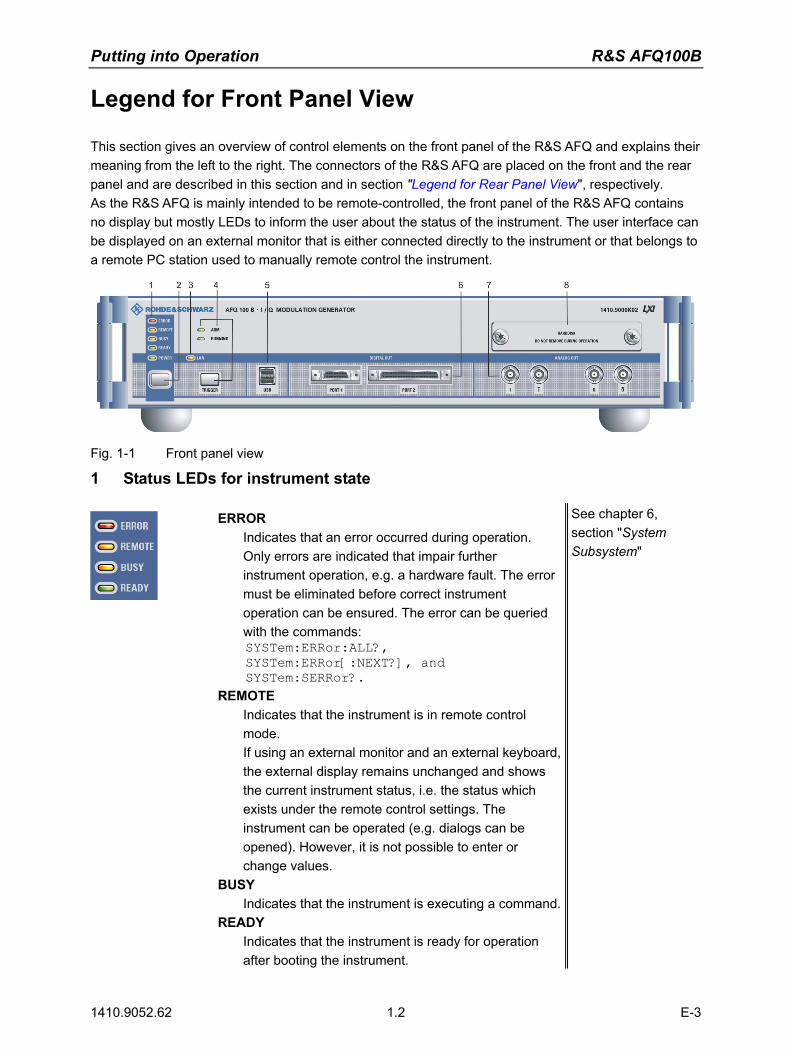
This section gives an overview of control elements on the front panel of the R&S AFQ and explains their meaning from the left to the right. The connectors of the R&S AFQ are placed on the front and the rear panel and are described in this section and in section "Legend for Rear Panel View", respectively. As the R&S AFQ is mainly intended to be remote-controlled, the front panel of the R&S AFQ contains no display but mostly LEDs to inform the user about the status of the instrument. The user interface can be displayed on an external monitor that is either connected directly to the instrument or that belongs to a remote PC station used to manually remote control the instrument.
Fig. 1-1 Front panel view
1 Status LEDs for instrument state
ERROR Indicates that an error occurred during operation. Only errors are indicated that impair further instrument operation, e.g. a hardware fault. The error must be eliminated before correct instrument operation can be ensured. The error can be queried with the commands: SYSTem:ERRor:ALL?, SYSTem:ERRor[:NEXT?], and SYSTem:SERRor?.
REMOTE Indicates that the instrument is in remote control mode. If using an external monitor and an external keyboard, the external display remains unchanged and shows the current instrument status, i.e. the status which exists under the remote control settings. The instrument can be operated (e.g. dialogs can be opened). However, it is not possible to enter or change values.
BUSY Indicates that the instrument is executing a command.
READY Indicates that the instrument is ready for operation after booting the instrument.
See chapter 6, section "System Subsystem"

R&S AFQ100B Putting into Operation
1410.9052.62 1.3 E-3
2 Switch
The on/off switch switches the instrument from the standby mode to the operating state provided the power switch at the instrument rear is switched on. The standby key switches the instrument from the standby mode to the operating mode and vice versa (toggle switch), provided that the power switch at the instrument´s rear panel is switched on.
POWER LED
The LED at the top left of the switch indicates the standby and ready state of the instrument.
Green Lighting green, the power LED indicates that the instrument is power supplied and ready for operation. Orange Lighting orange, the LED indicates that the instrument is in standby mode.
See section "Switching On" on page 1.17
CAUTION
Danger of shock hazard! The instrument is still power-supplied while it is in standby mode.
3 Status LED for LXI (LAN connection)
LAN
Indicates that the R&S AFQ is connected to an Ethernet LAN (local area network). The color of the LED display indicates the current status of the LAN connection: Green Indicates that LAN is active (normal operation). Green (flashing) Device identification. Red Indicates a LAN fault or no LAN connection.
The instrument is connected to the ethernet with the aid of a cable attached to the LAN interface at the rear of the instrument.
See data sheet and section "Connecting the R&S AFQ to a Network (LAN)" on page 1.26 and chapter 5, section "LAN Connector" and chapter 5, section "Remote Control via LAN Interface"
Putting into Operation R&S AFQ100B
1410.9052.62 1.4 E-3
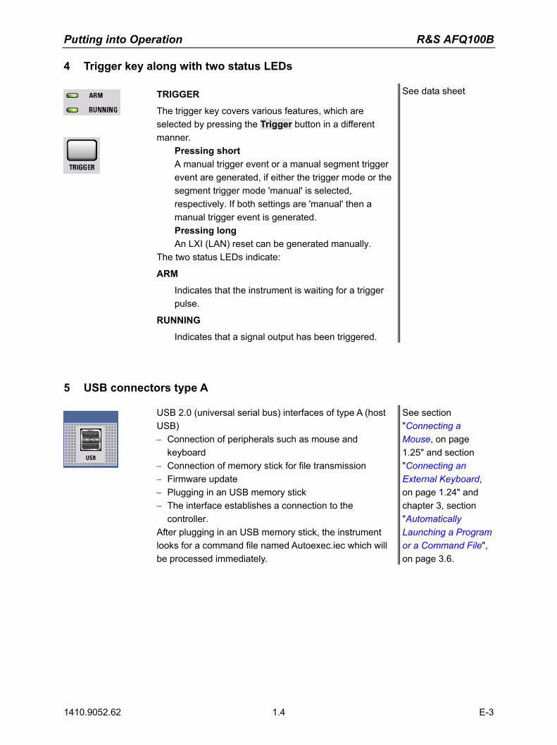
4 Trigger key along with two status LEDs
TRIGGER
The trigger key covers various features, which are selected by pressing the Trigger button in a different manner.
Pressing short A manual trigger event or a manual segment trigger event are generated, if either the trigger mode or the segment trigger mode 'manual' is selected, respectively. If both settings are 'manual' then a manual trigger event is generated. Pressing long An LXI (LAN) reset can be generated manually.
The two status LEDs indicate:
ARM
Indicates that the instrument is waiting for a trigger pulse.
RUNNING
Indicates that a signal output has been triggered.
See data sheet
5 USB connectors type A
USB 2.0 (universal serial bus) interfaces of type A (host USB) − Connection of peripherals such as mouse and
keyboard − Connection of memory stick for file transmission − Firmware update − Plugging in an USB memory stick − The interface establishes a connection to the
controller. After plugging in an USB memory stick, the instrument looks for a command file named Autoexec.iec which will be processed immediately.
See section "Connecting a Mouse, on page 1.25" and section "Connecting an External Keyboard, on page 1.24" and chapter 3, section "Automatically Launching a Program or a Command File", on page 3.6.

R&S AFQ100B Putting into Operation
1410.9052.62 1.5 E-3
6 Digital output
The instrument has two digital outputs, Port 1 and 2, featuring LVDS transmission: Port 1
This socket provides a multiplexed output to connect other R&S instruments, e.g. the R&S SMU Vector Signal Generator.
Port 2 The parallel output provides a 16 bit wide data bus for both I and Q channels via a 68-pole SCSI socket to connect test boards equipped with DACs.
Note: To avoid electromagnetic interference (EMI) only the cable R&S SMU-Z6 must be used for the connection to the digital interface. The associated cable is available under R&S part number 1415.0201.02
See chapter 8, "Maintenance and Remote Control Interfaces"
Notes on connecting an output device on Port1 and Port 2! 1) the LVDS output is held higher than 0.6 V The output common-mode voltage is not properly established if the LVDS output is held higher than 0.6V when the R&S AFQ is switched on. As consequence, the output will not work properly. 2) the common mode voltage is higher than 2.5 V Even if the the common mode voltage is applied for only a very short time, the output will back off. Example: If a DUT has pullups to 3V3 on both LVDS lines, it will pull these lines to 3V3. When the DUT is now connected to the R&S AFQ, the R&S AFQ will see this 3V3, at least for short time. Countermeasure: Power Up the DUT after powering the R&S AFQ. In both cases the output of the R&S AFQ will not be damaged and will return to work after reinitializing.
Putting into Operation R&S AFQ100B
1410.9052.62 1.6 E-3
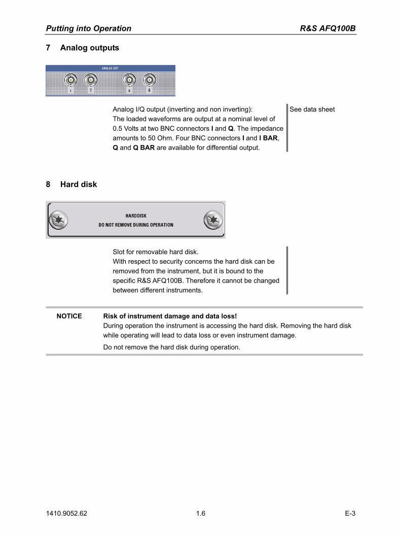
7 Analog outputs
Analog I/Q output (inverting and non inverting): The loaded waveforms are output at a nominal level of 0.5 Volts at two BNC connectors I and Q. The impedance amounts to 50 Ohm. Four BNC connectors I and I BAR, Q and Q BAR are available for differential output.
See data sheet
8 Hard disk
Slot for removable hard disk. With respect to security concerns the hard disk can be removed from the instrument, but it is bound to the specific R&S AFQ100B. Therefore it cannot be changed between different instruments.
NOTICE Risk of instrument damage and data loss! During operation the instrument is accessing the hard disk. Removing the hard disk while operating will lead to data loss or even instrument damage.
Do not remove the hard disk during operation.
R&S AFQ100B Putting into Operation
1410.9052.62 1.7 E-3
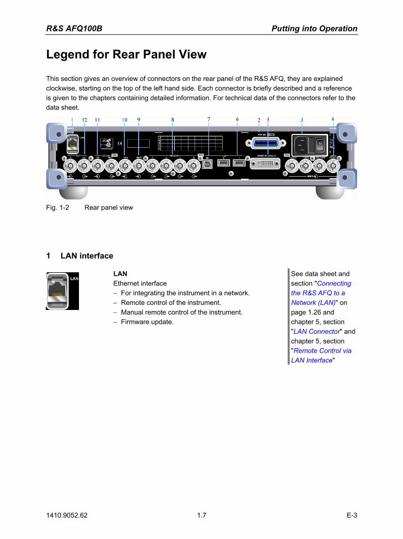
Legend for Rear Panel View
This section gives an overview of connectors on the rear panel of the R&S AFQ, they are explained clockwise, starting on the top of the left hand side. Each connector is briefly described and a reference is given to the chapters containing detailed information. For technical data of the connectors refer to the data sheet.
Fig. 1-2 Rear panel view
1 LAN interface
LAN Ethernet interface − For integrating the instrument in a network. − Remote control of the instrument. − Manual remote control of the instrument. − Firmware update.
See data sheet and section "Connecting the R&S AFQ to a Network (LAN)" on page 1.26 and chapter 5, section "LAN Connector" and chapter 5, section "Remote Control via LAN Interface"
Putting into Operation R&S AFQ100B
1410.9052.62 1.8 E-3
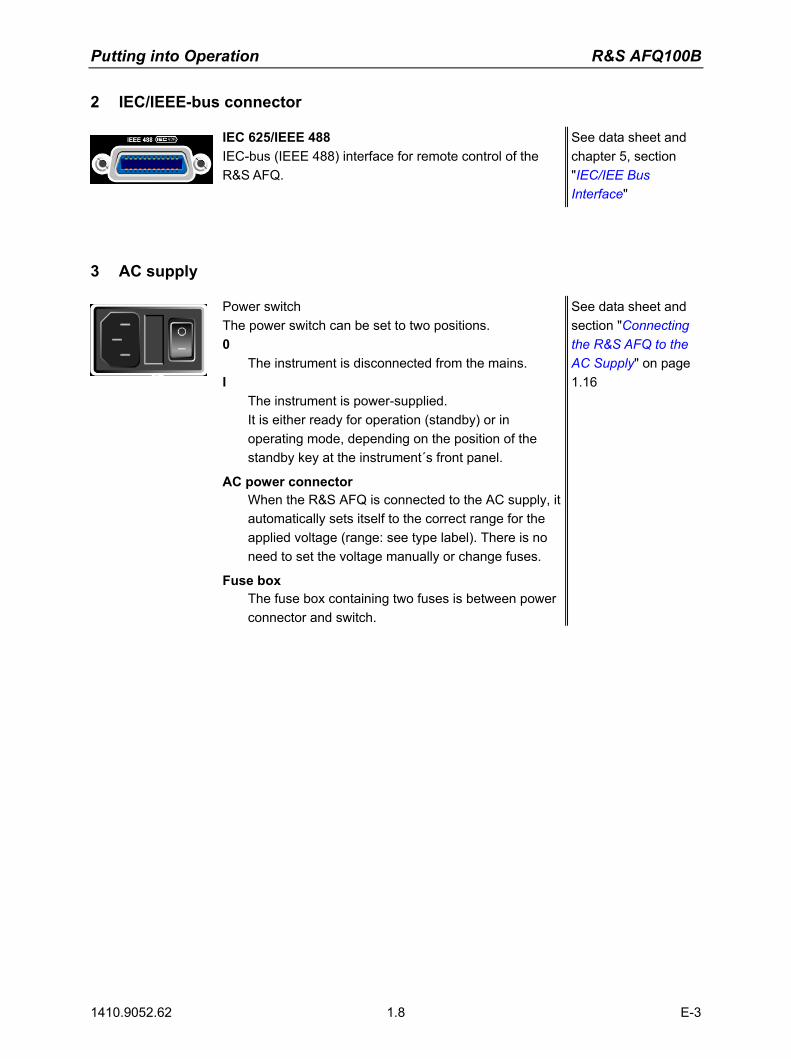
2 IEC/IEEE-bus connector
IEC 625/IEEE 488 IEC-bus (IEEE 488) interface for remote control of the R&S AFQ.
See data sheet and chapter 5, section "IEC/IEE Bus Interface"
3 AC supply
Power switch The power switch can be set to two positions. 0
The instrument is disconnected from the mains. I
The instrument is power-supplied. It is either ready for operation (standby) or in operating mode, depending on the position of the standby key at the instrument´s front panel.
AC power connector When the R&S AFQ is connected to the AC supply, it automatically sets itself to the correct range for the applied voltage (range: see type label). There is no need to set the voltage manually or change fuses.
Fuse box The fuse box containing two fuses is between power connector and switch.
See data sheet and section "Connecting the R&S AFQ to the AC Supply" on page 1.16

R&S AFQ100B Putting into Operation
1410.9052.62 1.9 E-3
4 BERT
Four BERT inputs
The BERT connectors either receive clock and data signals for measuring a bit error rate or, they receive control signals for segment hopping (FHOP) while generating multi segment waveforms. The sequence for segment hopping can be fed in parallel or serial.
Note: The FHOP mode disables the BERT functionality and vice versa.
See data sheet and chapter 4, section "Trigger Dialog"
CLOCK − Clock input from a DUT. − Clock input in mode FHOP serial. − Bit 3 (MSB) input in mode FHOP parallel. DATA − Demodulated data from DUT. − Data input in mode FHOP serial. − Bit 2 input in mode FHOP parallel. RESTART − This signal repeats BER measurements with short
signals. − The signal is not used in mode FHOP serial. − Bit 1 input in mode FHOP parallel. DATA ENABL − This signal labels the payload of the data, hence
header or guard signals do not contribute to the BER. − Strobe input in mode FHOP serial to mark the end of a
data sequence( LSB). − Bit 0 (LSB) input in mode FHOP parallel.

Putting into Operation R&S AFQ100B
1410.9052.62 1.10 E-3
5 Monitor
MONITOR ANALOG The 15-pin Sub-D female connector is intended for connecting an external VGA monitor with an analog input.
See data sheet and section "Connecting an External Monitor" on page 1.25
6 USB connectors type A
USB 2, 1 One USB 2.0 (universal serial bus) and one USB 1.1 interface of type A (host USB) Connection of peripherals such as mouse and
keyboard Connection of memory stick for file transmission Firmware update
The interface establishes a connection to the controller.
See section "Connecting a Mouse" on page 1.24 and section "Connecting an External Keyboard" on page 1.24
7 USB interface type B
IN One USB 2.0 (universal serial bus) interface of type B, hence the instrument is assigned as device, not as host. This connector may be used for remote controlling the instrument.
See data sheet
8 Marker (1-4)
MARKER 1-4 R&S AFQ provides four marker outputs for triggering and controlling external devices. The marker signals are either contained in the waveform or are user defined in the Marker dialog.
See data sheet and "Marker Dialog"

R&S AFQ100B Putting into Operation
1410.9052.62 1.11 E-3
9 Next
NEXT
This trigger input indicates the next (i.e. the 2nd, 3rd, 4th, ...) segment of a multi segment waveform, which can be a compound of e.g. a sine, a rectangular, and a sawtooth signal.
See data sheet and "Trigger Dialog"
10 Trigger input
TRIG
The output of the stored waveform can be triggered with a TTL signal applied to this connector. Trigger condition and polarity are user-selectable. The termination impedance is either 0,05 or 1 kOhm.
See data sheet and "Trigger Dialog"
11 Clock signal input/output
CLOCK IN, OUT
IN Input for external clock.
OUT Output with current memory clock rate..
See data sheet and "Clock Dialog"
12 Reference clock signal input/output
REF IN, OUT
IN Input for external 10 MHz reference clock.
OUT Output of internal 10 MHz reference clock.
See data sheet and "Clock Dialog"
Putting into Operation R&S AFQ100B
1410.9052.62 1.12 E-3
Putting into Operation
The following section describes the procedure for putting the instrument into operation and the connection of peripherals such as keyboard, mouse, and monitor. It contains general safety instructions for instrument operation.
The installation of options and the firmware update are described in chapter 4 of the service manual.
Unpacking the Instrument
Remove the instrument from its packaging and check the equipment for completeness using the delivery note and the accessory lists for the various items. First, pull off the polyethylene protection pads from the instrument's rear feet and then carefully remove the pads from the instrument handles at the front. Pull off the corrugated cardboard cover that protects the rear of the instrument. Carefully unthread the corrugated cardboard cover at the front that protects the instrument handles and remove it. Check the instrument for any damage. If there is damage, immediately contact the carrier who delivered the instrument. In this case, make sure not to discard the box and packing material.
It is advisable to keep the original packing material in order to prevent control elements and connectors from being damaged in case the instrument is to be transported or shipped at a later date.
Installing the Instrument in a 19" Rack
The instrument is designed for indoors use in a 19" rack. A rack adapter is required for installation in a 19" rack (refer to data sheet for Order No.). The mounting instructions are supplied with the adapter.
NOTICE Risk of overheating!
To less airflow for cooling may cause overheating of the instrument. Prior to putting the instrument into operation always check for space between the ventilation holes and the rack casing to get sufficient air supply in the rack

R&S AFQ100B Putting into Operation
1410.9052.62 1.13 E-3
Safety Instructions
General Precautions
NOTICE Instrument damage caused by disregarding the following precautions! Any non-compliance with the following precautions may cause damage to the instrument. Prior to putting the instrument into operation, check the following:
The covers of the housing are in place and screwed on. Vents are not obstructed. Make sure that the air can escape freely through the
vents at the rear and at the sides. The minimum distance to the wall should therefore be at least 10 cm.
The signal levels at the inputs do not exceed permissible limits. The outputs of the instrument are not overloaded or incorrectly connected.
This particularly applies to the maximum permissible back-feed at the outputs, which is specified in the data sheet.
The instrument should only be operated in horizontal position on an even surface. The ambient temperature must not exceed the range specified in the data sheet.
Also observe the instructions in the following sections and the general safety instructions at the beginning of this manual.
Protection against Electrostatic Discharge
To avoid damaging the electronic components of the EUT due to electrostatic discharge produced by contact, the use of appropriate protective measures is recommended.
EMC Safety Precautions
To avoid electromagnetic interference (EMI) only suitable, double shielded signal and control cables must be used. The clock output must be terminated properly (50 Ohms). Lines have to be terminated with 50 Ohm. Because of the high clock rates at the outputs, double shielded cables must be used to keep within permissible EMI limits at the REF IN/OUT,CLOCK IN/OUT TRIG/NEXT, and MARKER 1-4 connectors. USB devices must keep within permissible EMI limits.
Putting into Operation R&S AFQ100B
1410.9052.62 1.14 E-3
Setting up the Instrument
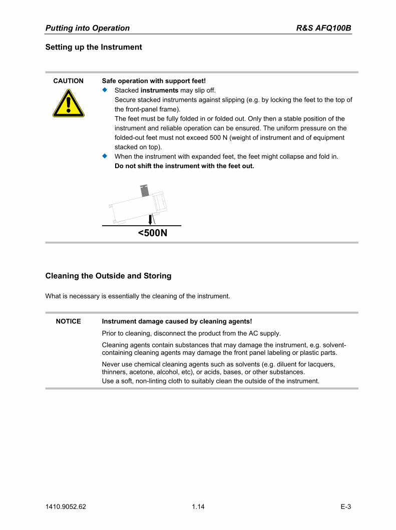
CAUTION
Safe operation with support feet! Stacked instruments may slip off.
Secure stacked instruments against slipping (e.g. by locking the feet to the top of the front-panel frame). The feet must be fully folded in or folded out. Only then a stable position of the instrument and reliable operation can be ensured. The uniform pressure on the folded-out feet must not exceed 500 N (weight of instrument and of equipment stacked on top).
When the instrument with expanded feet, the feet might collapse and fold in. Do not shift the instrument with the feet out.
<500N
Cleaning the Outside and Storing
What is necessary is essentially the cleaning of the instrument.
NOTICE Instrument damage caused by cleaning agents!
Prior to cleaning, disconnect the product from the AC supply.
Cleaning agents contain substances that may damage the instrument, e.g. solvent-containing cleaning agents may damage the front panel labeling or plastic parts.
Never use chemical cleaning agents such as solvents (e.g. diluent for lacquers, thinners, acetone, alcohol, etc), or acids, bases, or other substances. Use a soft, non-linting cloth to suitably clean the outside of the instrument.

R&S AFQ100B Putting into Operation
1410.9052.62 1.15 E-3
Removing and Installing the Hard Disk
For security reasons the R&S AFQ is equipped with a removable hard disk. The hard disk is located at the front of the instrument.
NOTICE Risk of instrument damage and data loss! During operation the instrument is accessing the hard disk. Removing the hard disk while operating will lead to data loss or even instrument damage.
Do not remove the hard disk during operation.
For removing process as follows: 1. Switch off instrument.2. Unscrew 2 milled screws at the hard disk cover.3. Take off the hard disk slide-module carefully.
Safe keeping: It is recommended to keep the hard disk in antistatic package in order to prevent damage to the disk.
For installing process as follows: 1. Unscrew the slot and remove the cover.2. Reassemble the hard disk by carefully sliding it into the slot.3. Remount the cover and screw-tighten it.The instrument now can be connected and power supplied.
Note: The hard disk is supplied with pre-installed software and adjustment data and therefore bound to the specific R&S AFQ. It cannot be replaced or installed in several R&S instruments. For replacing an inoperable hard disk refer to the Sevice Manual, Chapter 3 Service and Repair, or contact the R&S support center. The hard disk needs to be installed at an authorized R&S service shop.
Putting into Operation R&S AFQ100B
1410.9052.62 1.16 E-3
Connecting the R&S AFQ to the AC Supply
The R&S AFQ is automatically matched to the applied AC voltage (see rear panel). There is no need to set the voltage manually or change fuses. The AC supply connector is at the rear of the unit (see below).
The nominal voltage and frequencies ranges are displayed on the rear panel and quoted in the data sheet. Since the instrument is in compliance with safety class EN61010-1, it should only be connected to a socket with earthing contact.
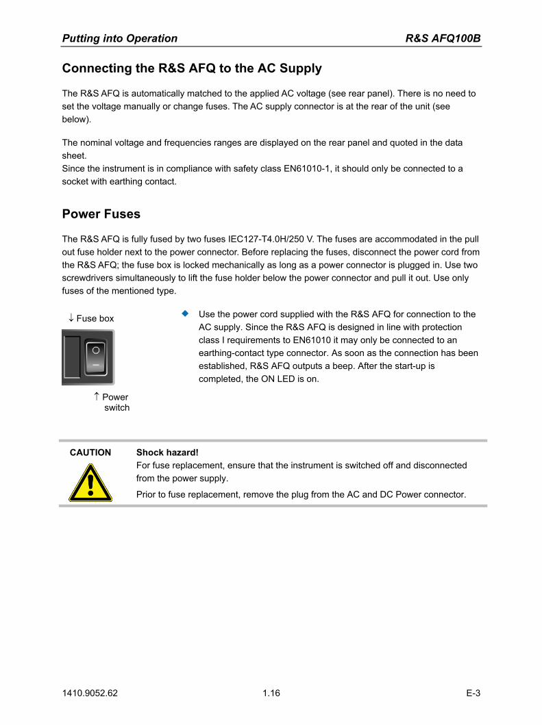
Power Fuses
The R&S AFQ is fully fused by two fuses IEC127-T4.0H/250 V. The fuses are accommodated in the pull out fuse holder next to the power connector. Before replacing the fuses, disconnect the power cord from the R&S AFQ; the fuse box is locked mechanically as long as a power connector is plugged in. Use two screwdrivers simultaneously to lift the fuse holder below the power connector and pull it out. Use only fuses of the mentioned type.
↓ Fuse box
↑ Power switch
Use the power cord supplied with the R&S AFQ for connection to the AC supply. Since the R&S AFQ is designed in line with protection class I requirements to EN61010 it may only be connected to an earthing-contact type connector. As soon as the connection has been established, R&S AFQ outputs a beep. After the start-up is completed, the ON LED is on.
CAUTION Shock hazard! For fuse replacement, ensure that the instrument is switched off and disconnected from the power supply.
Prior to fuse replacement, remove the plug from the AC and DC Power connector.

R&S AFQ100B Putting into Operation
1410.9052.62 1.17 E-3
Switching On
↓ Power connector
Fuse box ↑ ↑ Power switch
Connect the modulation generator to the AC supply by means of the supplied power cable. Press the main Power switch at the rear of the instrument to position I. After power-up the instrument is either ready for operation (STANDBY) or in operating mode, depending on the position of the POWER switch at the instrument´s front panel (see below).
Note: The power switch may remain on for any period of time. Switching off is required only if the instrument ought to be isolated from the AC supply completely.
Press the ON/STANDBY key at the front panel. Lighting green the LED at the top left of the switch indicates that the instrument is ready for operation (ON).
The instrument is ready for operation. All modules inside the instrument are supplied with power.
Putting into Operation R&S AFQ100B
1410.9052.62 1.18 E-3
Booting the R&S AFQ
After instrument switch-on, the R&S signal generator automatically performs a system check, boots the Windows XP operating system and subsequently boots the instrument firmware. If an external monitor is connected to the instrument, the installed BIOS version and the processor characteristics are indicated for a few seconds in the start display after instrument switch-on. During booting the status LEDs in the AFQ´s front panel start to flash counterclockwise.
Immediately disable firewall for Remote Desktop By default the firewall is on and remote desktop is disabled. Some actions require a different firewall configuration, e.g. connecting to the instrument via remote desktop. The firewall settings can be modified by pushing the trigger button during startup, i.e. while the LEDs are flashing. When the user connects to the instrument via remote desktop he is asked if he wants either permanently disable the firewall and enable the remote desktop or for the current session only.
NOTICE Risk of changing the firewall settings! Disabling the firewall or allowing exceptions may make the instrument more vulnerable to viruses and intruders.
It is recommended to restore the default firewall configuration after completing a task which requires modified settings.
After booting is completed, the front panel LED READY indicates that the instrument is ready to be operated. The settings that were active before the last switch-off are established. With an external monitor, the block diagram of the modulation generator is displayed.
Note: If the software stops unexpectedly, the instrument can be rebooted by pressing the STANDBY key for approx. 5 s.
R&S AFQ100B Putting into Operation
1410.9052.62 1.19 E-3
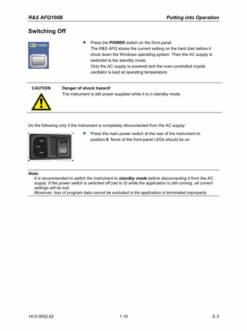
Switching Off
Press the POWER switch on the front panel. The R&S AFQ stores the current setting on the hard disk before it shuts down the Windows operating system. Then the AC supply is switched to the standby mode. Only the AC supply is powered and the oven-controlled crystal oscillator is kept at operating temperature.
CAUTION
Danger of shock hazard! The instrument is still power-supplied while it is in standby mode.
Do the following only if the instrument is completely disconnected from the AC supply:
Press the main power switch at the rear of the instrument to position 0. None of the front-panel LEDs should be on.
Note: It is recommended to switch the instrument to standby mode before disconnecting it from the AC supply. If the power switch is switched off (set to 0) while the application is still running, all current settings will be lost. Moreover, loss of program data cannot be excluded is the application is terminated improperly.
Putting into Operation R&S AFQ100B
1410.9052.62 1.20 E-3
Function Check
The instrument automatically monitors the main functions when the instrument is switched on and continuously during operation. If a fault is detected, the front panel LED ERROR indicates the error state. The error can be queried with commands SYSTem:ERRor:ALL?, SYSTem:ERRor[:NEXT], and SYSTem:SERRor. See chapter 6, section "System Subsystem" and chapter 9, Error Messages"). If an external monitor is connencted to the instrument, ERROR is displayed in the info line together with a brief error description. For in-depth identification of the error, click on the INFO button. In response, a description of the error(s) is displayed. Besides automatic monitoring of instrument functions, other capabilities in the R&S AFQ ensure correct functioning.
Internal Calibrations Calibrations can be performed with commands of the CALibrate Subsystem or in the Internal Adjustments dialog of the Setup - System menu (with external monitor and keyboard). Thus maximum level accuracy can be obtained, for instance. See chapter 6, section "Calibration Subsystem" and chapter 4, section "Calibration - Setup-System".
Test points Internal test points can be queried by the user with commands of the DIAGnostic Subsystem or in the Diagnostic dialog of the Setup - Test menu (with external monitor and keyboard). See chapter 6, section "Diagnostic Subsystem" and chapter 4, section "Diagnostic - Setup-Test".

R&S AFQ100B Putting into Operation
1410.9052.62 1.21 E-3
Default Settings
The instrument is set to a defined state with common command *RST or the Alt + P key combination on an external keyboard.
The following table gives an overview of the presets for the most important generator settings. The other presets can be found in the preset tables of the individual menus and the information accompanying the IEC/IEEE-bus commands.
Functions that concern the integration of the instrument into a measurement setup are not changed, e.g. IEC/IEEE bus address or reference oscillator source settings.
The list below the table shows the settings that are not affected by the PRESET key.
Reference frequency internal, calibration off
Offsets 0
Modulations switched off
IEC/IEEE-bus address not changed With preset, all parameters and switch states are preset, including those of deactivated operating modes. Presettings beyond those in the above list can be seen in the preset tables in chapter 4 or from the *RST values of the associated IEC/IEEE bus commands.
Settings that are not affected by the PRESET key
Reference frequency settings (Ref Oscillator menu) Network settings (Setup menu) IEC/IEEE-bus address (Setup menu) Password and settings protected by passwords (Setup menu) Start/Stop Gui Update (Setup menu) Display and keyboard settings (Setup menu). Save and Recall settings

Putting into Operation R&S AFQ100B
1410.9052.62 1.22 E-3
Windows XP
NOTICE Functions of the instrument may be impaired! Using not specifically authorized software may impair instrument functions.
Drivers and programs used in the instrument under Windows XP have been adapted tothe modulation generator. Existing software must only be modified with update software released by Rohde & Schwarz. Likewise, only programs authorized by Rohde & Schwarz for use on the instrument must be executed.
The following program packages have been successfully tested for compatibility with the measurement instrument software:
− Windows XP Remote Desktop − Symantec Norton AntiVirus � Virus-protection software
The I/Q modulation generator is equipped with the Windows XP operating system. The configuration of the operating system is optimally adapted to modulation generator functions in the factory. Changes in the system setup are only required when peripherals like a keyboard is installed or in the event that the network configuration does not comply with the default settings (see section "Connecting the R&S AFQ to a Network (LAN)",on page 1.26). After power-up of the modulation generator, the operating system boots and the instrument firmware is started automatically without a password query (auto login).
Note: Auto login is performed with the user name and the password "instrument". The standard user has administrator rights so that peripherals and network installations are possible.
The operating system can only be accessed if an external keyboard and/or a mouse and an external monitor are connected, an access via remote control commands is not possible. Windows XP provides an on-screen keyboard that can be operated using a mouse, thus enabling operation by mouse only. An external keyboard is recommended for extensive entries.
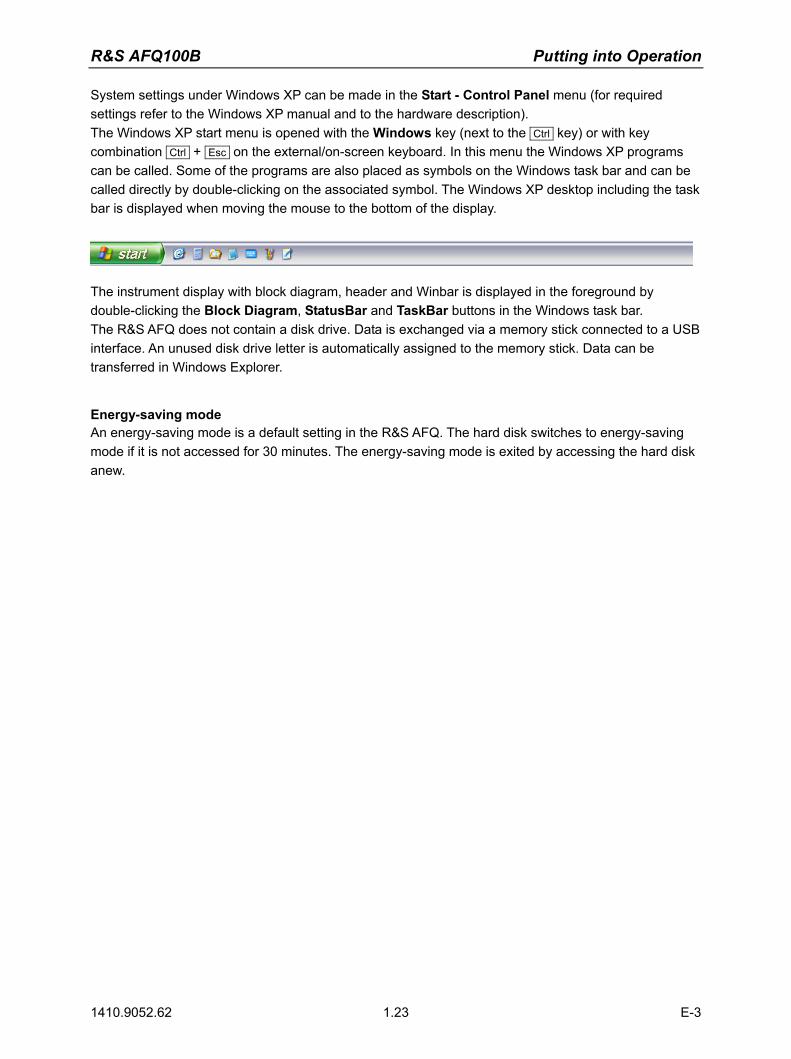
R&S AFQ100B Putting into Operation
1410.9052.62 1.23 E-3
System settings under Windows XP can be made in the Start - Control Panel menu (for required settings refer to the Windows XP manual and to the hardware description). The Windows XP start menu is opened with the Windows key (next to the Ctrl key) or with key combination Ctrl + Esc on the external/on-screen keyboard. In this menu the Windows XP programs can be called. Some of the programs are also placed as symbols on the Windows task bar and can be called directly by double-clicking on the associated symbol. The Windows XP desktop including the task bar is displayed when moving the mouse to the bottom of the display.
The instrument display with block diagram, header and Winbar is displayed in the foreground by double-clicking the Block Diagram, StatusBar and TaskBar buttons in the Windows task bar. The R&S AFQ does not contain a disk drive. Data is exchanged via a memory stick connected to a USB interface. An unused disk drive letter is automatically assigned to the memory stick. Data can be transferred in Windows Explorer.
Energy-saving mode An energy-saving mode is a default setting in the R&S AFQ. The hard disk switches to energy-saving mode if it is not accessed for 30 minutes. The energy-saving mode is exited by accessing the hard disk anew.
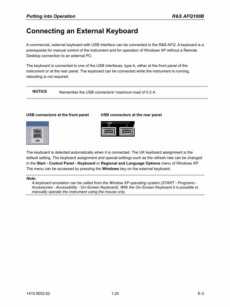
Putting into Operation R&S AFQ100B
1410.9052.62 1.24 E-3
Connecting an External Keyboard
A commercial, external keyboard with USB interface can be connected to the R&S AFQ. A keyboard is a prerequisite for manual control of the instrument and for operation of Windows XP without a Remote Desktop connection to an external PC. The keyboard is connected to one of the USB interfaces, type A, either at the front panel of the instrument or at the rear panel. The keyboard can be connected while the instrument is running, rebooting is not required.
NOTICE Remember the USB connectors' maximum load of 0.5 A.
USB connectors at the front panel USB connectors at the rear panel
The keyboard is detected automatically when it is connected. The UK keyboard assignment is the default setting. The keyboard assignment and special settings such as the refresh rate can be changed in the Start - Control Panel - Keyboard or Regional and Language Options menu of Windows XP. The menu can be accessed by pressing the Windows key on the external keyboard.
Note: A keyboard emulation can be called from the Window XP operating system (START - Programs - Accessories - Accessibility - On-Screen Keyboard). With the On-Screen Keyboard it is possible to manually operate the instrument using the mouse only.

R&S AFQ100B Putting into Operation
1410.9052.62 1.25 E-3
Connecting a Mouse
A commercial mouse with a USB interface can be connected to the R&S AFQ. A mouse simplifies control of the block diagram and of associated menus in manual control. It is sufficient for operation of Windows XP when used together with the on-screen keyboard.
The mouse is connected to one of the USB interfaces, type A, either at the front panel of the instrument or at the rear panel. The mouse can be connected while the instrument is running, rebooting is not required.
USB connector at the front panel USB connectors at the rear panel
The mouse is detected automatically when it is connected. Special settings such as mouse cursor speed etc, can be made in the Start - Control Panel - Mouse menu of Windows XP. The menu can be accessed by pressing the Windows key on the external keyboard.
Connecting an External Monitor
NOTICE Overvoltage hazard! Connecting a monitor while the instrument is switched on the monitor and instrument may be impaired. A monitor must not be connected until the instrument is switched off (standby). Prior to connect a monitor switch off the instrument. Do not modify the screen driver (Display type) and the display configuration since this will impair instrument operation.
An external monitor with an analog interface can be connected to the MONITOR connector on the rear panel of the R&S AFQ. An external monitor is a prerequisite for manual control of the instrument and for operation of Windows XP without a remote desktop connection to an external PC.
Connection
Before the external monitor is connected, the instrument must be switched off (standby mode) to prevent damage to the monitor and the R&S AFQ. After connection, the external monitor is detected when the instrument is started. The generator screen with all elements, e.g. block diagram, Winbar, etc, is then displayed on the external monitor and on the R&S AFQ. Further settings are not required.

Putting into Operation R&S AFQ100B
1410.9052.62 1.26 E-3
Connecting the R&S AFQ to a Network (LAN) The R&S AFQ is equipped with a network interface and can be connected to an Ethernet LAN (local area network). Provided the appropriate rights have been assigned by the network administrator and the Window XP firewall configuration is adapted accordingly, files can be transmitted via the network, and network resources, e.g. a network folder, can be used. The instrument can also be remote-controlled and manually controlled in the network. Manual network control means that the user can operate the R&S AFQ from any remote PC in the network via the Remote Desktop Connection which is provided for Windows PCs or via the Ultr@VNC connection which is provided for Linux/Unix and Windows PCs. For instance, the user can control one or more R&S AFQs from a desk that is part of a test assembly located in another section of the building (see section "Manual Remote Control via an External Controller" on page 1.35). Remote-control of the instrument via the LAN interface is described in chapter 5, section "Remote Control via LAN Interface". A firmware update via the LAN interface is described in chapter 2 of the service manual.
Connection to the Network
NOTICE Risk of network errors! Connecting errors may affect the entire network.
We recommend to coordinate the connection of the instrument to the network with the network administrator.
Do not connect or disconnect the network cable until the instrument is switched off (standby). Only then the network connection can be reliably detected and impairments to instrument operation can be avoided.
The instrument is connected to the LAN with the aid of a commercial RJ-45 cable suitable for a 10/100/1000Mbps connection attached to the LAN interface at the rear of the instrument.

R&S AFQ100B Putting into Operation
1410.9052.62 1.27 E-3
Configuring the R&S AFQ for Network Operation
The network interface functions with 10/100/1000Mbps Ethernet IEEE 802.3u. The TCP/IP network protocol and the associated network services are preconfigured. For data exchange in a LAN, each connected PC or instrument must be accessible via an IP address or via an unambiguous computer name. In addition, network access of the different users is organized by the assignment of access rights. Access rights determine which of the available network resources, e.g. data logging systems, are available to the R&S AFQ. The Window XP operating system is protected by an activated firewall per default. The configuration of the firewall has to be adapted according to the required network communication needs.
Networks using DHCP
The R&S AFQ is preconfigured for networks using DHCP (dynamic host configuration protocol). In these networks, an available IP address is automatically assigned to the R&S AFQ. In this case the generator is identified via an unambiguous computer name in the network. Each R&S AFQ is assigned a individual computer name in the factory. This name can be queried and changed in the Start - My Computer menu of Windows XP (see "Query Computer Name" below).
Networks using fixed IP addresses
In networks using fixed IP addresses, the addresses are mostly assigned by the network administrator. A fixed IP address must be entered in the Start - Control Panel menu of Windows XP.
Point-to-Point Connection
To build a simple network - just an LAN connection between the R&S AFQ and a controller without integration into a larger network - an IP address has to be assigned to the R&S AFQ and the controller. For such purposes, the IP addresses 192.168.xxx.yyy are available .The value range for xxx and yyy is 1...254, the value for the subnet mask is always 255.255.255.0. For this type of connection, a commercial cross-over RJ-45 cable is used.
User name and password
The user "instrument" is assigned to the R&S AFQ. The user name is used for auto-login when the instrument is started and for manual remote-control. The password is also "instrument". By asigning the respective rights, the network administrator decides which directories and resources in the network can be accessed by the R&S AFQ.
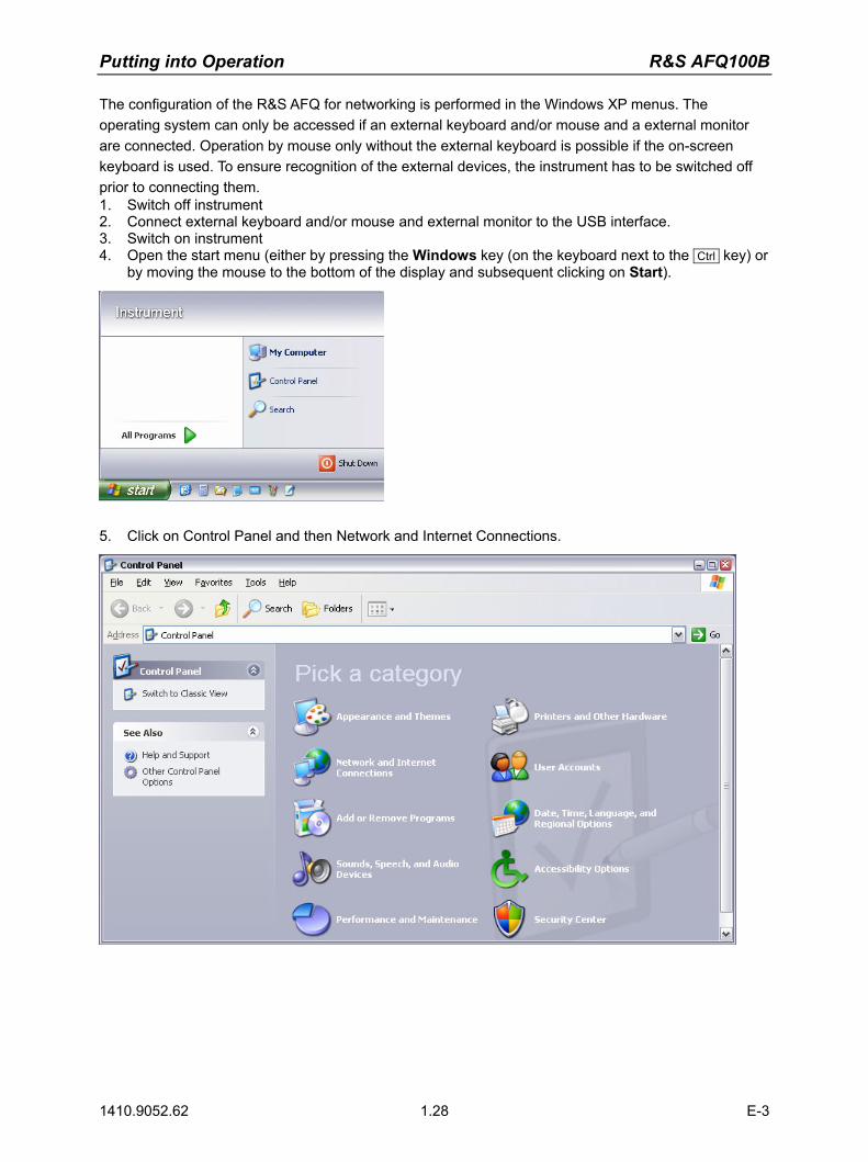
Putting into Operation R&S AFQ100B
1410.9052.62 1.28 E-3
The configuration of the R&S AFQ for networking is performed in the Windows XP menus. The operating system can only be accessed if an external keyboard and/or mouse and a external monitor are connected. Operation by mouse only without the external keyboard is possible if the on-screen keyboard is used. To ensure recognition of the external devices, the instrument has to be switched off prior to connecting them. 1. Switch off instrument 2. Connect external keyboard and/or mouse and external monitor to the USB interface. 3. Switch on instrument 4. Open the start menu (either by pressing the Windows key (on the keyboard next to the Ctrl key) or
by moving the mouse to the bottom of the display and subsequent clicking on Start).
5. Click on Control Panel and then Network and Internet Connections.
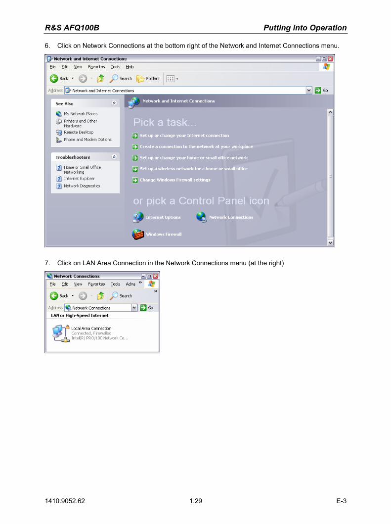
R&S AFQ100B Putting into Operation
1410.9052.62 1.29 E-3
6. Click on Network Connections at the bottom right of the Network and Internet Connections menu.
7. Click on LAN Area Connection in the Network Connections menu (at the right)
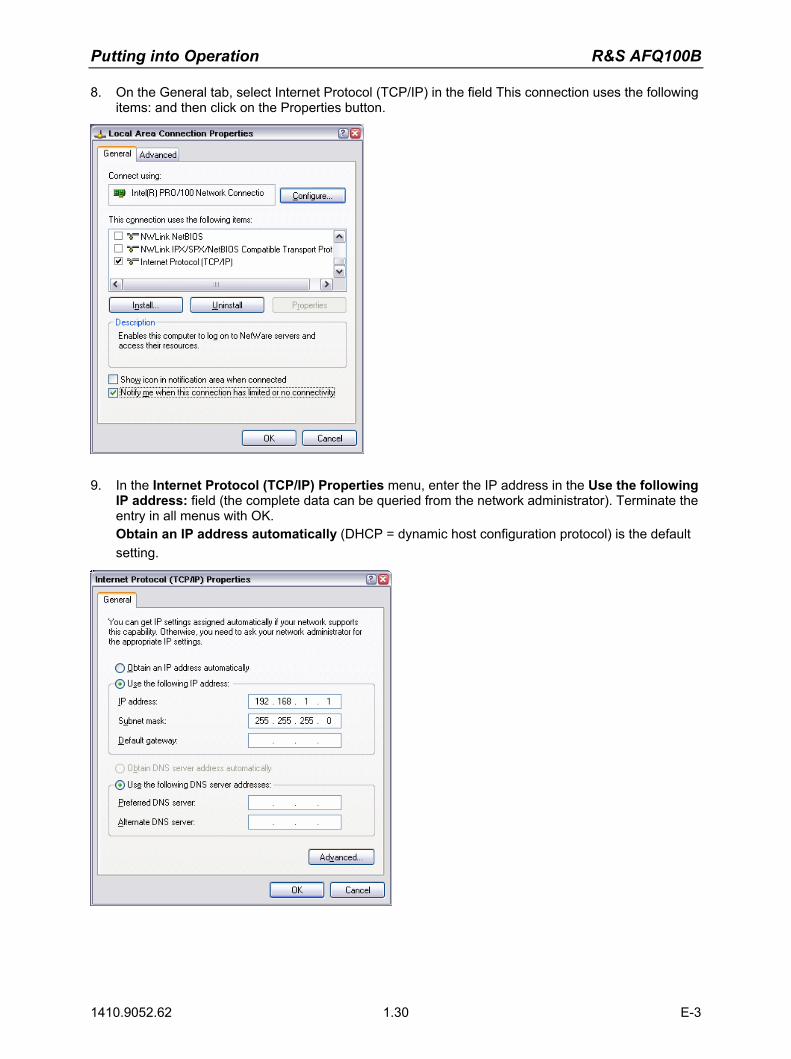
Putting into Operation R&S AFQ100B
1410.9052.62 1.30 E-3
8. On the General tab, select Internet Protocol (TCP/IP) in the field This connection uses the following items: and then click on the Properties button.
9. In the Internet Protocol (TCP/IP) Properties menu, enter the IP address in the Use the following
IP address: field (the complete data can be queried from the network administrator). Terminate the entry in all menus with OK. Obtain an IP address automatically (DHCP = dynamic host configuration protocol) is the default setting.

R&S AFQ100B Putting into Operation
1410.9052.62 1.31 E-3
Query Computer Name
1. Open the start menu, select My Computer and open the context menu by pressing the right mouse key.
2. Click on Properties and select the Computer Name tab in the menu.
The computer name is displayed under Full Computer Name:. The name can be changed in the Change submenu.
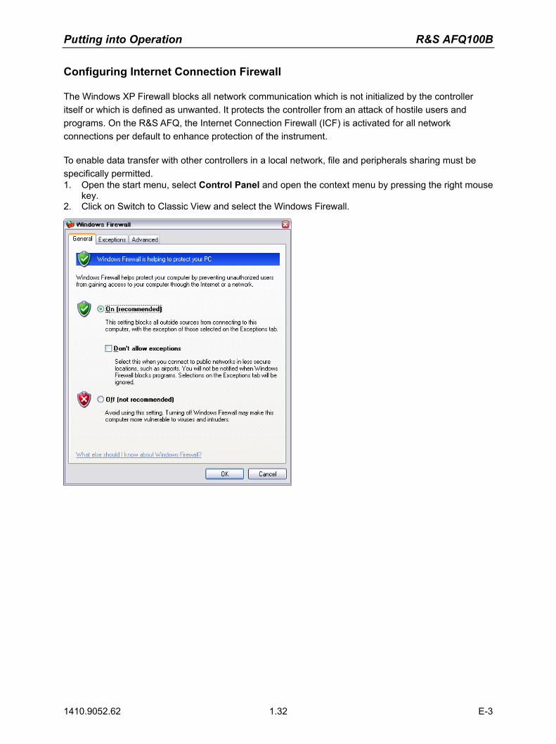
Putting into Operation R&S AFQ100B
1410.9052.62 1.32 E-3
Configuring Internet Connection Firewall
The Windows XP Firewall blocks all network communication which is not initialized by the controller itself or which is defined as unwanted. It protects the controller from an attack of hostile users and programs. On the R&S AFQ, the Internet Connection Firewall (ICF) is activated for all network connections per default to enhance protection of the instrument. To enable data transfer with other controllers in a local network, file and peripherals sharing must be specifically permitted. 1. Open the start menu, select Control Panel and open the context menu by pressing the right mouse
key. 2. Click on Switch to Classic View and select the Windows Firewall.

R&S AFQ100B Putting into Operation
1410.9052.62 1.33 E-3
3. Select tab Exceptions and activate check box File and Printer Sharing. Confirm entry with Ok,
Accessing Directories in the Network
Access to network drives depends on access rights and whether the drives in question have been enabled. The complete integration of the R&S AFQ into a larger network with the necessary allocation of rights is highly complex and normally performed by a network administrator. However, the hard disk of a computer also connected to the network can be accessed from the R&S AFQ relatively easily. The only precondition for this is that the desired directory the R&S AFQ should access is enabled on the remote computer. Subsequently, this directory is accessed from the R&S AFQ using a Windows XP search function. This procedure is also of importance for a point-to-point connection, for instance in order to start a firmware update for which the files have been stored on the hard disk of the remote computer.
Note: The computer and the modulation generator must both be equipped with a computer name and an IP address (see section "Configuring the R&S AFQ for Network Operation").

Putting into Operation R&S AFQ100B
1410.9052.62 1.34 E-3
Enabling the desired directory on the remote computer
Note: The menu name may deviate from the name specified in the operating sequence, depending on the language and on the operating system used on the computer.
1. On the computer, in Windows Explorer mark the directory to be enabled and open the Properties
menu with the right-hand mouse button. 2. In the Sharing panel, activate the Share this folder checkbox. 3. Write down the name of the computer (see section "Query Computer Name").
Accessing the enabled directory on the R&S AFQ 1. Call the Start menu. 2. In the Search menu, select Computers or People and then A Computer on the Network. 3. In the input window of the query Which Computer you are looking for?, enter the computer name
and start the search by pressing the Enter key. The computer and its name appears in the results list.
4. Click on the computer's name to display the enabled directory. The files in this directory can be used in the R&S AFQ.
Note: If a user name and password are requested when you click on the computer, the login name and password used on the computer must be entered.
R&S AFQ100B Putting into Operation
1410.9052.62 1.35 E-3
Manual Remote Control via an External Controller
The R&S AFQ can be manually remote-controlled from an external PC via a network link. This allows convenient operation of the vector modulation generator from the desktop although the instrument is integrated in a rack in the next room.
Manual remote control in contrast to remote control does not use remote-control commands but a separate software which is installed on the external PC. After its start, the software simulates the user interface of the R&S AFQ. The instrument can thus be manually operated from the PC as on the unit itself.
A precondition for manual remote control is a connection between modulation generator and PC via a LAN network and the installation of the software on the PC and on the R&S AFQ. Two free-of-charge programs are available for setting up the connection for manual remote control: The Windows program Remote Desktop Connection for PCs with Window operating system and the program Ultr@VNC for PCs with Linux/Unix or Windows operating system. After the connection is established, the modulation generator screen with the block diagram is displayed on the external PC and the R&S AFQ can be manually remote-controlled from the external PC. The individual functions are operated using the mouse and keyboard. Specific instrument functions can be executed using specific key combinations on the keyboard (see table in chapter 3, section "Legend of Manual Controls" on page 3.2). Installation of the remote-control software and establishing the connection between external PC and modulation generator is described in the following.
Configuration for Manual Remote Control via Windows Remote Desktop Connection
The instrument is operated with the aid of the Windows program Remote Desktop Connection which is provided free-of-charge by Microsoft in the download area of the Internet (http://www.microsoft.com). Manual remote control of the modulation generator via Remote Desktop is possible under the following conditions:
The Windows 95 operating system or higher and the Remote Desktop Connection program are installed on the external PC and a LAN interface is configured for the network.
The modulation generator and PC are linked via a LAN. The Remote Desktop Connection is enabled on the R&S AFQ R&S AFQ data (IP address or computer name of the R&S AFQ in the network) is entered in the
Remote Desktop Connection program of the external PC. Login on the external computer for the R&S AFQ was carried out with the correct user name
(instrument) and the correct password (instrument).

Putting into Operation R&S AFQ100B
1410.9052.62 1.36 E-3
NOTICE Risk of unauthorized access!
After activation of the remote desktop, any user on the network who knows the computer name and login data of the vector modulation generator can access this R&S AFQ. Even after cutting it, the connection is still enabled and the R&S AFQ can be accessed any time. To disable the connection, the remote desktop must be deactivated on the R&S AFQ.
Enable Remote Desktop Connection on R&S AFQ
The configuration is performed in the Windows XP menus. The operating system can only be accessed if an external keyboard and monitor is connected. A mouse is recommended for convenient operation of Windows XP. To ensure recognition of the external devices, the instrument has to be switched off prior to connecting them. 1. Switch off the instrument. 2. Connect the external keyboard, mouse and monitor to the USB interface. 3. Switch on the instrument. 4. Open the start menu. 5. Select My Computer and open the context menu by pressing the right mouse key.
6. Click on Properties and select the Remote tab in the menu.

R&S AFQ100B Putting into Operation
1410.9052.62 1.37 E-3
7. Activate check box Allow users to connect remotely to this computer and close window with theOK button.
Note: When activating/locking the Remote Desktop, the associated firewall settings are automatically enabled/disabled.
Install Remote Desktop and Establish Connection on the Windows PC
The Remote Desktop Connection program of Microsoft is available on the Internet for the Windows 95 operating system and its successors as a free-of-charge download. Following the instructions on the Internet, it can be loaded onto any external PC. For the Windows XP operating system, the program is already preinstalled.
1. Install Remote Desktop Connection program on the PC if required.2. Start program in the Start - All Programs - Accessories - Communications window.
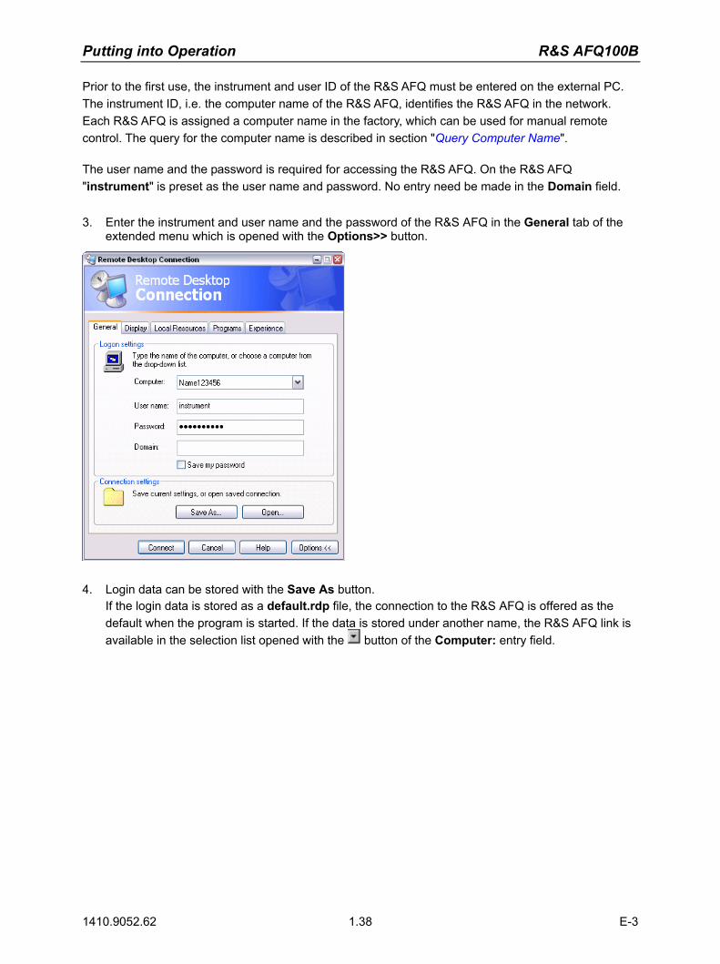
Putting into Operation R&S AFQ100B
1410.9052.62 1.38 E-3
Prior to the first use, the instrument and user ID of the R&S AFQ must be entered on the external PC. The instrument ID, i.e. the computer name of the R&S AFQ, identifies the R&S AFQ in the network. Each R&S AFQ is assigned a computer name in the factory, which can be used for manual remote control. The query for the computer name is described in section "Query Computer Name". The user name and the password is required for accessing the R&S AFQ. On the R&S AFQ "instrument" is preset as the user name and password. No entry need be made in the Domain field.
3. Enter the instrument and user name and the password of the R&S AFQ in the General tab of the
extended menu which is opened with the Options>> button.
4. Login data can be stored with the Save As button.
If the login data is stored as a default.rdp file, the connection to the R&S AFQ is offered as the default when the program is started. If the data is stored under another name, the R&S AFQ link is available in the selection list opened with the button of the Computer: entry field.

R&S AFQ100B Putting into Operation
1410.9052.62 1.39 E-3
5. Enter remote desktop size 800 x 600 in the Display tab.
6. The connection is established when the Connect button is pressed.
After the connection is established, the modulation generator screen with the block diagram is displayed and the R&S AFQ can be manually remote-controlled from the external PC. The individual functions are operated using the mouse and keyboard. Specific instrument functions can be executed using specific key combinations on the keyboard (see table in chapter 3, section "Legend of Manual Controls" on page 3.2). The device firmware of the R&S AFQ is disabled when the connection is set up. Direct control on the R&S AFQ is not possible while manual remote-control is active. The access of an external PC is indicated by the logon screen of Windows XP which identifies the accessing user. If several R&S AFQ instruments are to be manually remote-controlled from one PC, a separate Remote Desktop Control window must be opened for each R&S AFQ. This is possible by starting the program on the external PC several times.
Cut Manual Remote Control Connection via Remote Desktop
The connection can be cut either on the R&S AFQ or on the external PC. Cutting the connection does not disable it. It can be established again any time.
Cutting the connection on the modulation generator
Cutting the connection requires external keyboard, mouse and monitor. 1. Click on Disconnect in the remote-control message menu of the R&S AFQ
The connection is cut, a message on the external PC informs about the disconnection.

Putting into Operation R&S AFQ100B
1410.9052.62 1.40 E-3
Cutting the connection on the external PC 1. Open the start menu. 2. Click on Disconnect in the lower right-hand corner of menu
Disable Manual Remote Control Connection via Remote Desktop
The connection can be disabled by deactivating the Remote Desktop on the R&S AFQ. 1. Open the start menu with the Windows key, select My Computer and open the context menu by
pressing the right mouse key. 2. Click on Properties and select the Remote tab in the menu. 3. Deactivate check box Allow users to connect remotely to this computer and close window with
the OK button. The connection is disabled, it is no longer possible to access the R&S AFQ for manual remote control via Remote Desktop.

R&S AFQ100B Putting into Operation
1410.9052.62 1.41 E-3
Configuration for Manual Remote Control via Ultr@VNC
The instrument is operated with the aid of the program Ultr@VNC. The program is included in operating system Linux/Unix. It is available as a free-of-charge download on the internet for operating system Window XP (http://ultravnc.sourceforge.net/download.htm) Manual remote control of the modulation generator is possible under the following conditions:
The external PC with Linux/Unix or Windows operating system (Windows 95 or higher) is equipped with a LAN interface which is configured for the network.
The modulation generator and PC are linked via a LAN. The Ultr@VNC program is installed and enabled on the R&S AFQ, and an user-specific password
for the VNC connection is defined. Communication on the network via Ultr@VNC program is enabled in the firewall.
PC with Linux/Unix operating system The R&S AFQ IP address is entered in the address line of the internet browser of the external PC and the user-specific password for the VNC connection is entered in the request panel.
PC with Windows operating system The Ultr@VNC Viewer program component is installed on the external PC The R&S AFQ IP address and the user-specific password for the VNC connection are entered in the VNC Viewer panel.
NOTICE Risk of unauthorized access!
After enabling the VNC connection, any user on the network who knows the password and IP address of the I/Q modulation generator can access this R&S AFQ. Even after cutting it, the connection is still enabled and the R&S AFQ can be accessed any time. To disable the connection, the VNC program on the R&S AFQ must be uninstalled or the VNC server service disabled. To enhance security, also communication on the network via Ultr@VNC program should be disabled in the firewall.
Install and Enable VNC Connection on R&S AFQ
The Ultr@VNC program is available on the Internet as a free-of-charge download. Following the instructions on the Internet, it can be copied onto the R&S AFQ. 1. Download the program from the internet and copy it to a directory that can be accessed by the
R&S AFQ. 2. Switch off the instrument. 3. Connect a mouse, a keyboard and an external monitor. 4. Switch on the instrument. 5. Shut down firmware using the Alt-F4 key combination. 6. Start installation by double-clicking the setup file (Ultr@VNC_100_RC18_setup.exe / whereas 18
denotes the version number).
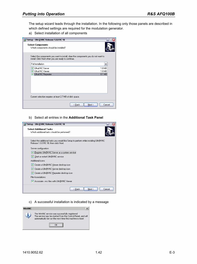
Putting into Operation R&S AFQ100B
1410.9052.62 1.42 E-3
The setup wizard leads through the installation. In the following only those panels are described in which defined settings are required for the modulation generator. a) Select installation of all components
b) Select all entries in the Additional Task Panel
c) A successful installation is indicated by a message

R&S AFQ100B Putting into Operation
1410.9052.62 1.43 E-3
d) At the same time a warning is displayed stating that a password must be set.
e) After clicking on OK in the warning panel the Default Local System Properties panel opens. A password with a length of at least five digits must be entered. This password is used on the remote PC to access the R&S AFQ. Other settings may be changed according to the user-specific security requirements.
7. After the installation the VNC connection must be enabled in the ICF firewall (see following
section). After the installation the program and the operating system are always started automatically. An icon
is placed on the right side of the Windows XP task bar (notification area). On mouse over, the IP address of the R&S AFQ is indicated. This IP address and the user-defined password are the prerequisites to enable manual remote control on the PC. A cut connection is indicated by a changed color of the icon. Cutting the connection does not disable it. It can be established again any time.

Putting into Operation R&S AFQ100B
1410.9052.62 1.44 E-3
Configuring Internet Connection Firewall for VNC Connection
To enable manual remote control by other controllers in a local network via VNC connection, the connection must be specifically permitted in the firewall. 1. Open the start menu, select Control Panel and open the context menu by pressing the right mouse
key. 2. Click on Switch to Classic View and select the Windows Firewall.
3. Select tab Exceptions and call sub menu Add Program...

R&S AFQ100B Putting into Operation
1410.9052.62 1.45 E-3
4. Select Run Ultr@VNC SERVER and click on Ok. 5. Activate check box Run Ultr@VNC SERVER in the Exception tab and click on Ok.
Establish Manual Remote Control on the Linux/Unix PC
The VNC program is available per default for Linux/Unix operating systems. Only three steps are necessary to establish the connection to the R&S AFQ: 1. Start the internet browser on the PC. 2. Enter the following address:
vnc://"IP-address of R&S AFQ", e.g. vnc://192.168.1.1 3. Confirm with the Enter key.
The password for the remote VNC connection is requested. 4. Enter the password defined in the Default Local System Properties panel of the Ultr@VNC
program of R&S AFQ. 5. Press the Log On button to confirm. After the connection is established, the current modulation generator screen with the block diagram is displayed and the R&S AFQ can be manually remote-controlled from the external PC. The individual functions are operated using the mouse and keyboard. Specific instrument functions can be executed using specific key combinations on the keyboard (see table in chapter 3, section "Legend of Manual Controls" on page 3.2). In contrast to Remote Control Desktop, direct control on the R&S AFQ is possible while manual remote-control is established, it can be performed alternately with the manual remote control.
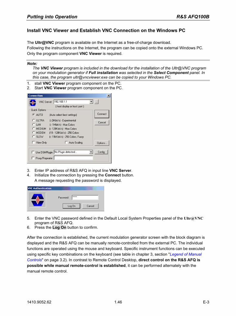
Putting into Operation R&S AFQ100B
1410.9052.62 1.46 E-3
Install VNC Viewer and Establish VNC Connection on the Windows PC
The Ultr@VNC program is available on the Internet as a free-of-charge download. Following the instructions on the Internet, the program can be copied onto the external Windows PC. Only the program component VNC Viewer is required.
Note: The VNC Viewer program is included in the download for the installation of the Ultr@VNC program on your modulation generator if Full installation was selected in the Select Component panel. In this case, the program [email protected] can be copied to your Windows PC.
1. stall VNC Viewer program component on the PC. 2. Start VNC Viewer program component on the PC.
3. Enter IP address of R&S AFQ in input line VNC Server. 4. Initialize the connection by pressing the Connect button.
A message requesting the password is displayed.
5. Enter the VNC password defined in the Default Local System Properties panel of the Ultr@VNC
program of R&S AFQ. 6. Press the Log On button to confirm. After the connection is established, the current modulation generator screen with the block diagram is displayed and the R&S AFQ can be manually remote-controlled from the external PC. The individual functions are operated using the mouse and keyboard. Specific instrument functions can be executed using specific key combinations on the keyboard (see table in chapter 3, section "Legend of Manual Controls" on page 3.2). In contrast to Remote Control Desktop, direct control on the R&S AFQ is possible while manual remote-control is established, it can be performed alternately with the manual remote control.
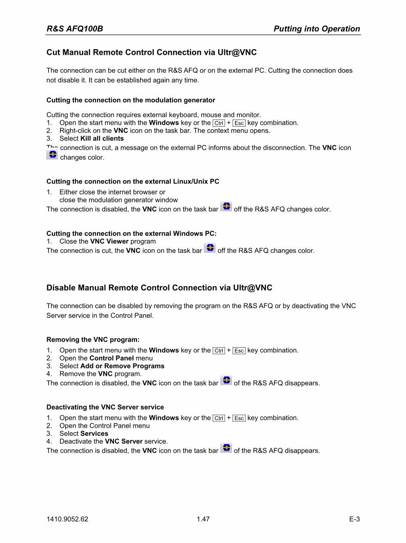
R&S AFQ100B Putting into Operation
1410.9052.62 1.47 E-3
Cut Manual Remote Control Connection via Ultr@VNC
The connection can be cut either on the R&S AFQ or on the external PC. Cutting the connection does not disable it. It can be established again any time.
Cutting the connection on the modulation generator
Cutting the connection requires external keyboard, mouse and monitor. 1. Open the start menu with the Windows key or the Ctrl + Esc key combination. 2. Right-click on the VNC icon on the task bar. The context menu opens. 3. Select Kill all clients The connection is cut, a message on the external PC informs about the disconnection. The VNC icon
changes color.
Cutting the connection on the external Linux/Unix PC 1. Either close the internet browser or
close the modulation generator window The connection is disabled, the VNC icon on the task bar off the R&S AFQ changes color.
Cutting the connection on the external Windows PC: 1. Close the VNC Viewer program The connection is cut, the VNC icon on the task bar off the R&S AFQ changes color.
Disable Manual Remote Control Connection via Ultr@VNC
The connection can be disabled by removing the program on the R&S AFQ or by deactivating the VNC Server service in the Control Panel.
Removing the VNC program: 1. Open the start menu with the Windows key or the Ctrl + Esc key combination. 2. Open the Control Panel menu 3. Select Add or Remove Programs 4. Remove the VNC program. The connection is disabled, the VNC icon on the task bar of the R&S AFQ disappears.
Deactivating the VNC Server service 1. Open the start menu with the Windows key or the Ctrl + Esc key combination. 2. Open the Control Panel menu 3. Select Services 4. Deactivate the VNC Server service. The connection is disabled, the VNC icon on the task bar of the R&S AFQ disappears.
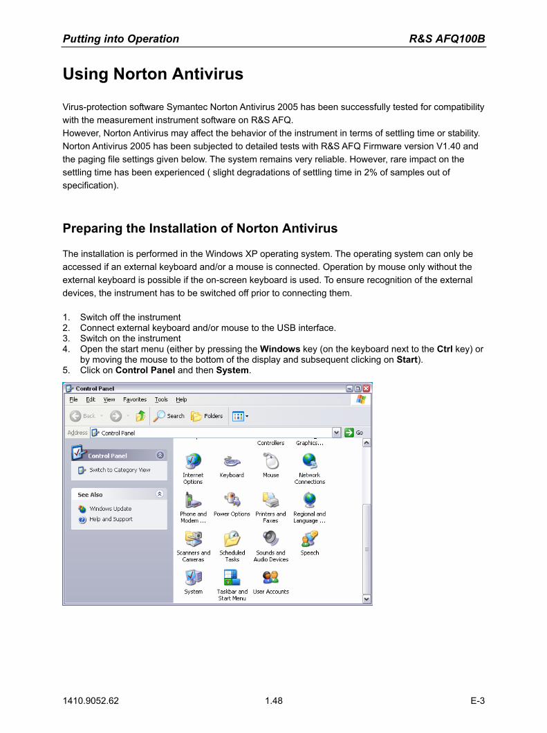
Putting into Operation R&S AFQ100B
1410.9052.62 1.48 E-3
Using Norton Antivirus
Virus-protection software Symantec Norton Antivirus 2005 has been successfully tested for compatibility with the measurement instrument software on R&S AFQ. However, Norton Antivirus may affect the behavior of the instrument in terms of settling time or stability. Norton Antivirus 2005 has been subjected to detailed tests with R&S AFQ Firmware version V1.40 and the paging file settings given below. The system remains very reliable. However, rare impact on the settling time has been experienced ( slight degradations of settling time in 2% of samples out of specification).
Preparing the Installation of Norton Antivirus
The installation is performed in the Windows XP operating system. The operating system can only be accessed if an external keyboard and/or a mouse is connected. Operation by mouse only without the external keyboard is possible if the on-screen keyboard is used. To ensure recognition of the external devices, the instrument has to be switched off prior to connecting them. 1. Switch off the instrument 2. Connect external keyboard and/or mouse to the USB interface. 3. Switch on the instrument 4. Open the start menu (either by pressing the Windows key (on the keyboard next to the Ctrl key) or
by moving the mouse to the bottom of the display and subsequent clicking on Start). 5. Click on Control Panel and then System.

R&S AFQ100B Putting into Operation
1410.9052.62 1.49 E-3
6. Select the Advanced and click on Performance Settings
7. Click on the Change button
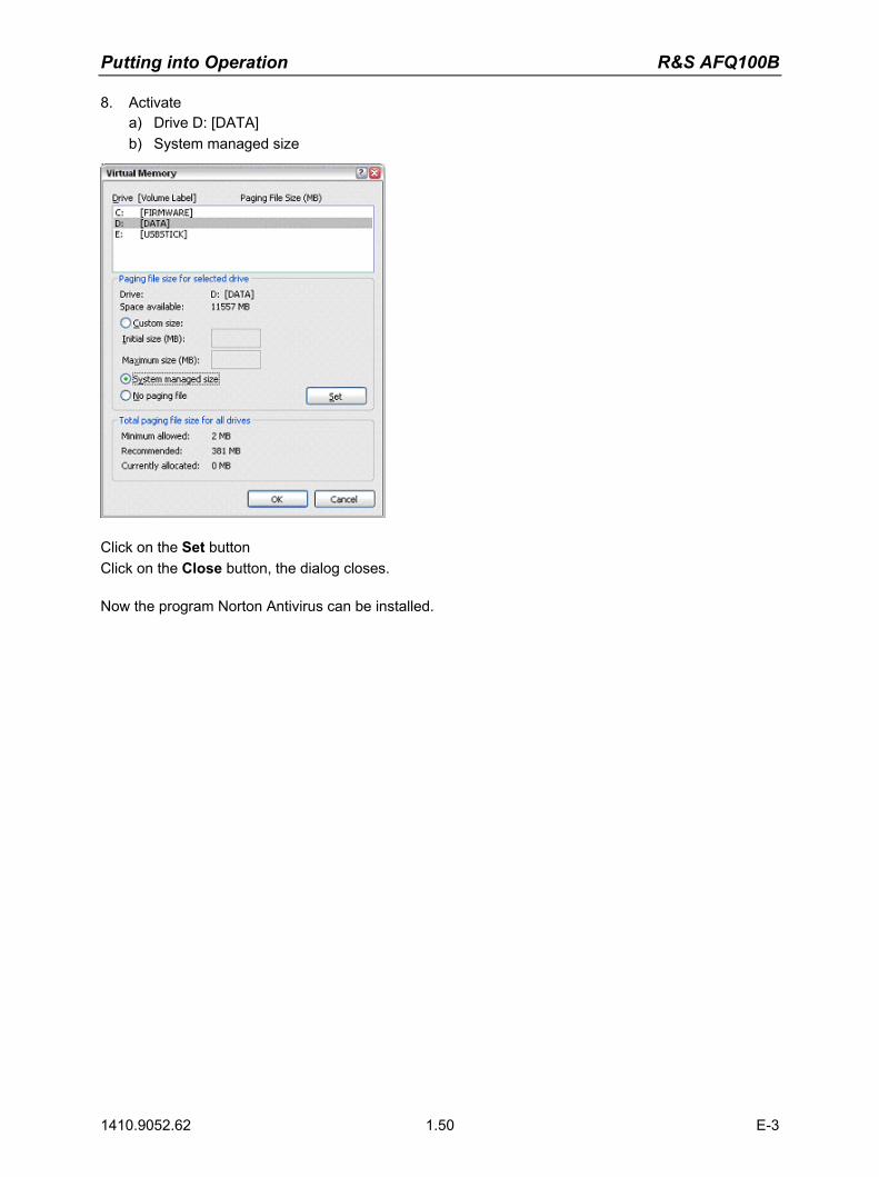
Putting into Operation R&S AFQ100B
1410.9052.62 1.50 E-3
8. Activate a) Drive D: [DATA] b) System managed size
Click on the Set button Click on the Close button, the dialog closes. Now the program Norton Antivirus can be installed.

R&S AFQ100B Contents - Getting Started
1410.9052.62 I-1 E-3
Contents - Chapter 2 "Getting Started"
2 Getting Started ................................................................................2.1
Outline of the Instrument .................................................................................. 2.1 Schematic Description......................................................................... 2.1 Use of the Instrument .......................................................................... 2.2
Main Applications ............................................................................................. 2.3 Feature Summary............................................................................................. 2.4 Block Diagram .................................................................................................. 2.5 Two ways to operate the instrument ................................................................ 2.6

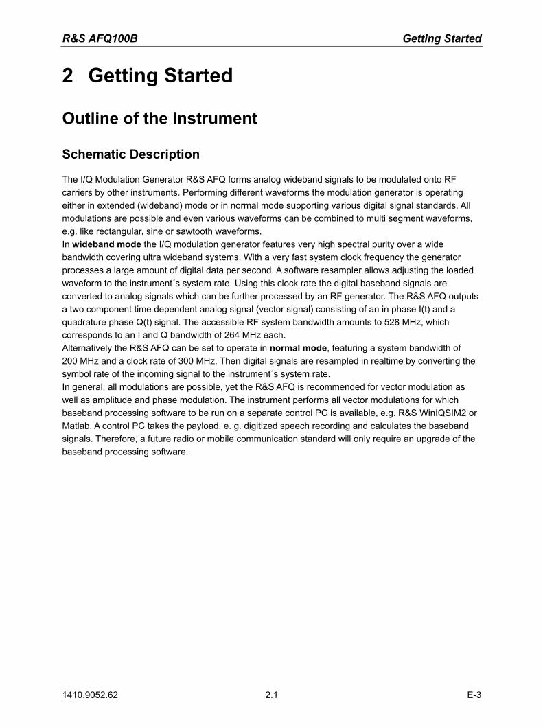
R&S AFQ100B Getting Started
1410.9052.62 2.1 E-3
2 Getting Started
Outline of the Instrument
Schematic Description
The I/Q Modulation Generator R&S AFQ forms analog wideband signals to be modulated onto RF carriers by other instruments. Performing different waveforms the modulation generator is operating either in extended (wideband) mode or in normal mode supporting various digital signal standards. All modulations are possible and even various waveforms can be combined to multi segment waveforms, e.g. like rectangular, sine or sawtooth waveforms. In wideband mode the I/Q modulation generator features very high spectral purity over a wide bandwidth covering ultra wideband systems. With a very fast system clock frequency the generator processes a large amount of digital data per second. A software resampler allows adjusting the loaded waveform to the instrument´s system rate. Using this clock rate the digital baseband signals are converted to analog signals which can be further processed by an RF generator. The R&S AFQ outputs a two component time dependent analog signal (vector signal) consisting of an in phase I(t) and a quadrature phase Q(t) signal. The accessible RF system bandwidth amounts to 528 MHz, which corresponds to an I and Q bandwidth of 264 MHz each. Alternatively the R&S AFQ can be set to operate in normal mode, featuring a system bandwidth of 200 MHz and a clock rate of 300 MHz. Then digital signals are resampled in realtime by converting the symbol rate of the incoming signal to the instrument´s system rate. In general, all modulations are possible, yet the R&S AFQ is recommended for vector modulation as well as amplitude and phase modulation. The instrument performs all vector modulations for which baseband processing software to be run on a separate control PC is available, e.g. R&S WinIQSIM2 or Matlab. A control PC takes the payload, e. g. digitized speech recording and calculates the baseband signals. Therefore, a future radio or mobile communication standard will only require an upgrade of the baseband processing software.

Getting Started R&S AFQ100B
1410.9052.62 2.2 E-3
Use of the Instrument
Common Use
The instrument loads waveforms calculated by simulation software such as Matlab or R&S WinIQSIM2 into its sample memory. After resampling the waveform is D/A converted and output at the I and Q connectors. The two component analog baseband signal is forwarded to a vector signal generator, such as R&S SMU. The vector signal generator modulates it onto an RF carrier and transmits the radio signal to an antenna. Finally, the device under test will receive the radio signal. The received signal can be checked for transmission errors using the instrument's bit error rate measurement feature.
The graphic shows the signal flow from baseband processing, i.e. waveform calculation, to the receiver, the DUT.
Special Use for Ultra Wideband Systems
Covering a spectral range from 3.1 to 10.6 GHz a UWB MB-OFDM (Multiband Orthogonal Frequency Division Multiplexing) signal is divided into 14 bands, 528 MHz each. According to the UWB frequency plan the 528 MHz bands are grouped together into band groups, covering 3 bands in a group. For each band group several TFCs (Time Frequency Code) are defined for frequency hopping inside one band group. The R&S AFQ supports the frequency hopping by a HOP marker signal which is output to the RF instrument connected in series.

R&S AFQ100B Getting Started
1410.9052.62 2.3 E-3
Main Applications
R&S AFQ is mainly used for generating modulation signals for an RF generator to check the data taken by a receiver. Moreover, RF generators with I/Q inputs can also be tested. Gain and phase of the two channels I and Q can be adjusted, hence accounting for non ideal characteristics of the RF generator to be driven. For test purposes, modulation signals are output at the digital output (option R&S AFQ-B18) of the instrument prior to D/A-conversion. In addition, the impairment of the digital signal is possible, delay, gain, voltage offset and phase mismatch. Pre-distortions are useful for compensating calibration errors of the instrument to be driven. Beyond this, the user can check the influence on the rate of successfully transmitted bits. Differences in amplitude between the I and Q channels give rise to an offset in the constellation diagram and thus to a narrower eye width for the modulation. Quadrature offsets can be illustrated by an I/Q vector diagram:
I
Q
Ideal modulation vector
Resultingmodulation vector
Error vector
Constellation Diagram
The main applications are:
bit error rate testing of baseband and RF devices testing semiconductor devices which process baseband signals testing transceivers and demodulators developing wireless communication systems checking how sensitive devices are with regard to impairments adjusting I/Q RF modulators developing of UWB communication systems testing radar devices testing modules and devices of digital modulation in production testing modules and devices with digital I/Q interfaces in production, e.g. fast digital analog
converters fast production testing with multi segment waveforms
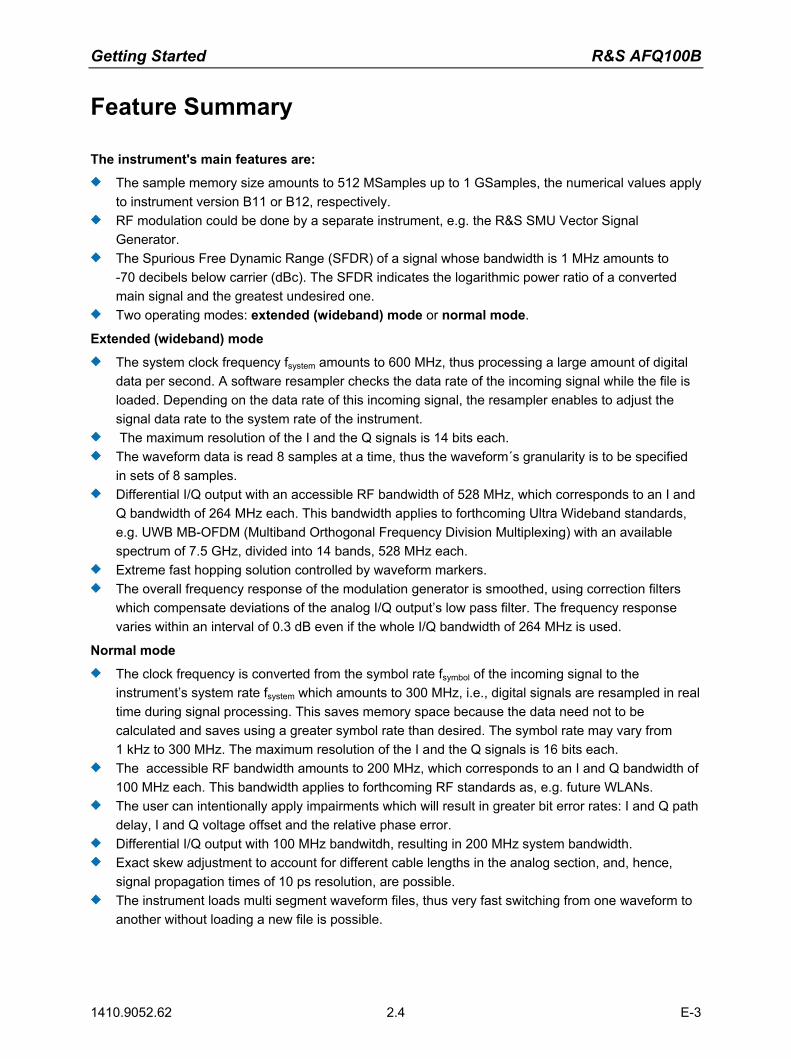
Getting Started R&S AFQ100B
1410.9052.62 2.4 E-3
Feature Summary
The instrument's main features are:
The sample memory size amounts to 512 MSamples up to 1 GSamples, the numerical values apply to instrument version B11 or B12, respectively.
RF modulation could be done by a separate instrument, e.g. the R&S SMU Vector Signal Generator.
The Spurious Free Dynamic Range (SFDR) of a signal whose bandwidth is 1 MHz amounts to -70 decibels below carrier (dBc). The SFDR indicates the logarithmic power ratio of a converted main signal and the greatest undesired one.
Two operating modes: extended (wideband) mode or normal mode.
Extended (wideband) mode
The system clock frequency fsystem amounts to 600 MHz, thus processing a large amount of digital data per second. A software resampler checks the data rate of the incoming signal while the file is loaded. Depending on the data rate of this incoming signal, the resampler enables to adjust the signal data rate to the system rate of the instrument.
The maximum resolution of the I and the Q signals is 14 bits each. The waveform data is read 8 samples at a time, thus the waveform´s granularity is to be specified
in sets of 8 samples. Differential I/Q output with an accessible RF bandwidth of 528 MHz, which corresponds to an I and
Q bandwidth of 264 MHz each. This bandwidth applies to forthcoming Ultra Wideband standards, e.g. UWB MB-OFDM (Multiband Orthogonal Frequency Division Multiplexing) with an available spectrum of 7.5 GHz, divided into 14 bands, 528 MHz each.
Extreme fast hopping solution controlled by waveform markers. The overall frequency response of the modulation generator is smoothed, using correction filters
which compensate deviations of the analog I/Q output�s low pass filter. The frequency response varies within an interval of 0.3 dB even if the whole I/Q bandwidth of 264 MHz is used.
Normal mode
The clock frequency is converted from the symbol rate fsymbol of the incoming signal to the instrument�s system rate fsystem which amounts to 300 MHz, i.e., digital signals are resampled in real time during signal processing. This saves memory space because the data need not to be calculated and saves using a greater symbol rate than desired. The symbol rate may vary from 1 kHz to 300 MHz. The maximum resolution of the I and the Q signals is 16 bits each.
The accessible RF bandwidth amounts to 200 MHz, which corresponds to an I and Q bandwidth of 100 MHz each. This bandwidth applies to forthcoming RF standards as, e.g. future WLANs.
The user can intentionally apply impairments which will result in greater bit error rates: I and Q path delay, I and Q voltage offset and the relative phase error.
Differential I/Q output with 100 MHz bandwitdh, resulting in 200 MHz system bandwidth. Exact skew adjustment to account for different cable lengths in the analog section, and, hence,
signal propagation times of 10 ps resolution, are possible. The instrument loads multi segment waveform files, thus very fast switching from one waveform to
another without loading a new file is possible.
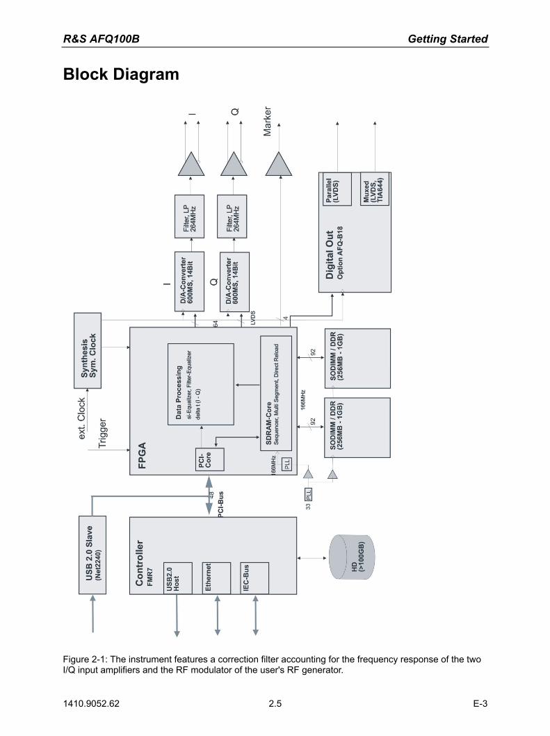
R&S AFQ100B Getting Started
1410.9052.62 2.5 E-3
Block Diagram
Figure 2-1: The instrument features a correction filter accounting for the frequency response of the two I/Q input amplifiers and the RF modulator of the user's RF generator.

Getting Started R&S AFQ100B
1410.9052.62 2.6 E-3
Two ways to operate the instrument
There are two possibilities to operate the instrument:
1. Using the instrument's own graphical user interface (GUI)a) stand alone, plugging in an external monitor, keyboard, and mouse directlyb) using Windows XP Pro's Remote Desktop feature or the program VNC via LAN, as described inthe first chapter.
2. Remote controla) via IEC-Bus, via LAN (LXI), or USB 2.0 using the USB type B connector at the rear panel.b) via a PC running Matlab or R&S' WinIQSIM2 software.
Note: The latter possibility only applies to forthcoming versions of the instrument.
A Windows software package WinIQSIM2 is available for generating external waveform files on a PC, it is included among the items and services supplied with the instrument. WinIQSIM2 can process very large data arrays. Furthermore, the instruments loads waveform files calculated by the previous software release.
It is also possible to transfer signals that have been calculated using a mathematical program such as Matlab (see also Application Note 1MA28, IQWizard - I/Q Signal Measurement and Conversion, which can be obtained by visiting the Rohde&Schwarz web site at http://www.rohde-schwarz.com).
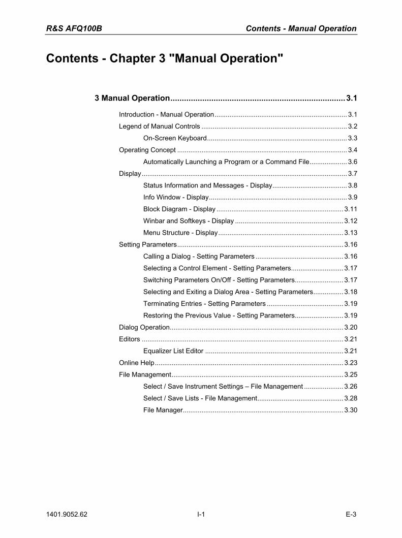
R&S AFQ100B Contents - Manual Operation
1401.9052.62 I-1 E-3
Contents - Chapter 3 "Manual Operation"
3 Manual Operation.............................................................................3.1
Introduction - Manual Operation....................................................................... 3.1 Legend of Manual Controls .............................................................................. 3.2
On-Screen Keyboard........................................................................... 3.3 Operating Concept ........................................................................................... 3.4
Automatically Launching a Program or a Command File.................... 3.6 Display.............................................................................................................. 3.7
Status Information and Messages - Display........................................ 3.8 Info Window - Display.......................................................................... 3.9 Block Diagram - Display .................................................................... 3.11 Winbar and Softkeys - Display .......................................................... 3.12 Menu Structure - Display................................................................... 3.13
Setting Parameters......................................................................................... 3.16 Calling a Dialog - Setting Parameters ............................................... 3.16 Selecting a Control Element - Setting Parameters............................ 3.17 Switching Parameters On/Off - Setting Parameters.......................... 3.17 Selecting and Exiting a Dialog Area - Setting Parameters................ 3.18 Terminating Entries - Setting Parameters ......................................... 3.19 Restoring the Previous Value - Setting Parameters.......................... 3.19
Dialog Operation............................................................................................. 3.20 Editors ............................................................................................................ 3.21
Equalizer List Editor .......................................................................... 3.21 Online Help..................................................................................................... 3.23 File Management............................................................................................ 3.25
Select / Save Instrument Settings � File Management ..................... 3.26 Select / Save Lists - File Management.............................................. 3.28 File Manager...................................................................................... 3.30


R&S AFQ100B Introduction - Manual Operation
1410.9052.62 3.1 E-3
3 Manual Operation
Introduction - Manual Operation
The present chapter describes the manual control of the R&S AFQ, even though the modulation generator is primarily intended to be remote-controlled via the GPIB interface or a LAN connection. Manual control using an external monitor, mouse and keyboard or from an external PC via a network link might help the user to get familiar with the instrument. The chapter includes a description of screenshots, operation of menus and the block diagram and the setting of parameters in dialogs.
The introduction into remote control is provided in chapter 5 "Remote Control - Basics".
The instrument can be operated manually either via the interactive block diagram or via a menu tree. All menus are in the form of windows that can be operated in the same way. Key combinations on the external keyboard or alternatively a mouse allow direct access to entries and settings. A keyboard emulation menu can be called from the Windows XP operating system (START - Programs - Accessories - Accessibility - On-Screen Keyboard). Thus, operation via mouse only is possible. An overview of the key combinations can be found in the following section "Legend of Manual Controls". The clear-cut display shows the current modulation generator state. Graphs can be called for a visual check of the output signal. Numerous help functions support the user in signal configuration.
Chapter 4 "Instrument Functions" includes a detailed description of modulation generator functions. Remote control of the instrument is described in chapter 5 "Remote Control - Basics" and chapter 6 "Remote Control Commands".
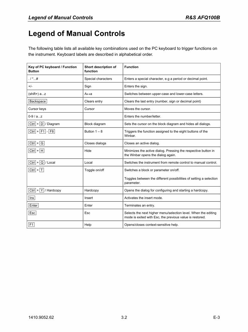
Legend of Manual Controls R&S AFQ100B
1410.9052.62 3.2 E-3
Legend of Manual Controls
The following table lists all available key combinations used on the PC keyboard to trigger functions on the instrument. Keyboard labels are described in alphabetical order. Key of PC keyboard / Function Button
Short description of function
Function
. / *...# Special characters Enters a special character, e.g a period or decimal point.
+/- Sign Enters the sign.
(shift+) a...z A↔a Switches between upper-case and lower-case letters.
Backspace Clears entry Clears the last entry (number, sign or decimal point)
Cursor keys Cursor Moves the cursor.
0-9 / a...z Enters the number/letter.
Ctrl + D / Diagram Block diagram Sets the cursor on the block diagram and hides all dialogs.
Ctrl + F1 - F8 Button 1 � 8 Triggers the function assigned to the eight buttons of the Winbar.
Ctrl + G Closes dialogs Closes an active dialog.
Ctrl + H Hide Minimizes the active dialog. Pressing the respective button in the Winbar opens the dialog again.
Ctrl + Q / Local Local Switches the instrument from remote control to manual control.
Ctrl + T Toggle on/off Switches a block or parameter on/off. Toggles between the different possibilities of setting a selection parameter.
Ctrl + Y / Hardcopy Hardcopy Opens the dialog for configuring and starting a hardcopy.
Ins Insert Activates the insert mode.
Enter Enter Terminates an entry.
Esc Esc Selects the next higher menu/selection level. When the editing mode is exited with Esc, the previous value is restored.
F1 Help Opens/closes context-sensitive help.
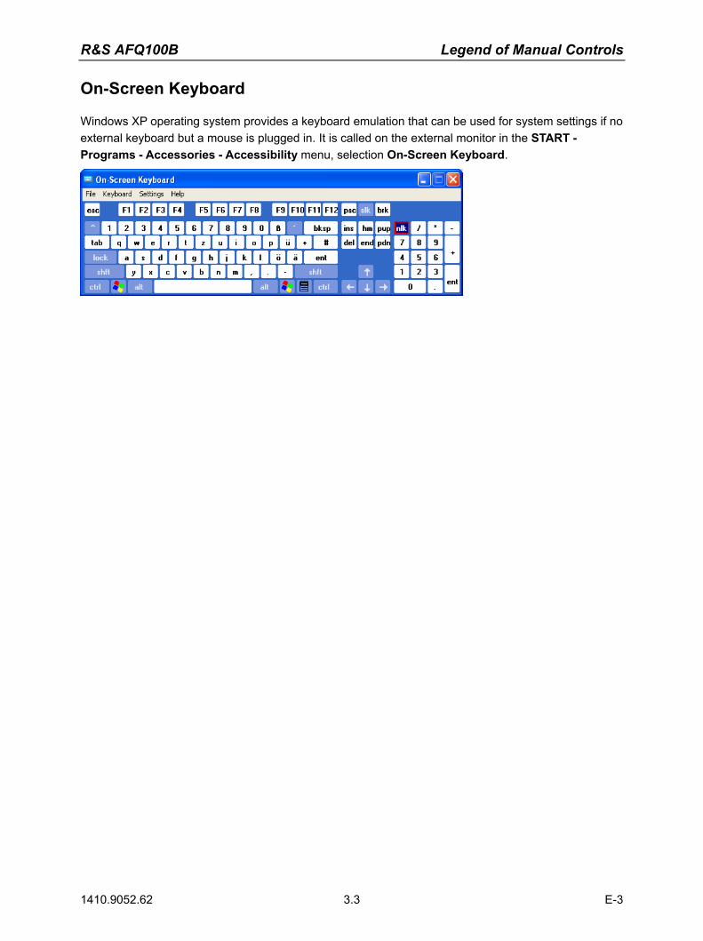
R&S AFQ100B Legend of Manual Controls
1410.9052.62 3.3 E-3
On-Screen Keyboard
Windows XP operating system provides a keyboard emulation that can be used for system settings if no external keyboard but a mouse is plugged in. It is called on the external monitor in the START - Programs - Accessories - Accessibility menu, selection On-Screen Keyboard.
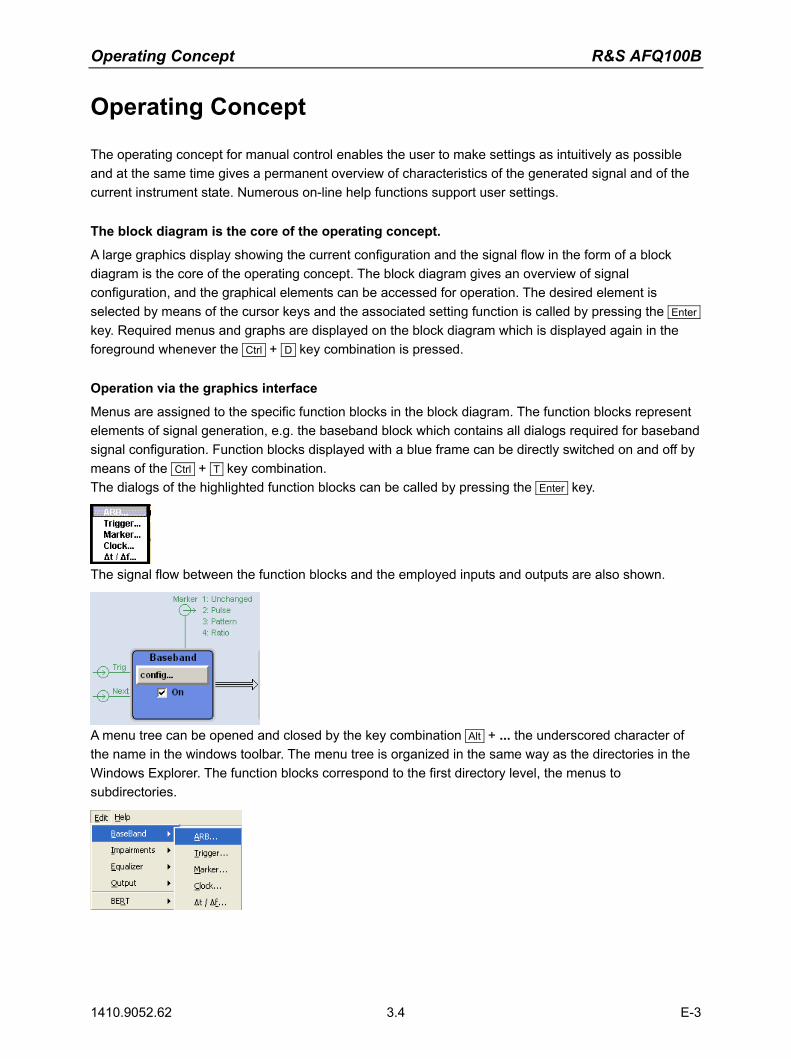
Operating Concept R&S AFQ100B
1410.9052.62 3.4 E-3
Operating Concept
The operating concept for manual control enables the user to make settings as intuitively as possible and at the same time gives a permanent overview of characteristics of the generated signal and of the current instrument state. Numerous on-line help functions support user settings.
The block diagram is the core of the operating concept.
A large graphics display showing the current configuration and the signal flow in the form of a block diagram is the core of the operating concept. The block diagram gives an overview of signal configuration, and the graphical elements can be accessed for operation. The desired element is selected by means of the cursor keys and the associated setting function is called by pressing the Enter key. Required menus and graphs are displayed on the block diagram which is displayed again in the foreground whenever the Ctrl + D key combination is pressed.
Operation via the graphics interface
Menus are assigned to the specific function blocks in the block diagram. The function blocks represent elements of signal generation, e.g. the baseband block which contains all dialogs required for baseband signal configuration. Function blocks displayed with a blue frame can be directly switched on and off by means of the Ctrl + T key combination. The dialogs of the highlighted function blocks can be called by pressing the Enter key.
The signal flow between the function blocks and the employed inputs and outputs are also shown.
A menu tree can be opened and closed by the key combination Alt + ... the underscored character of the name in the windows toolbar. The menu tree is organized in the same way as the directories in the Windows Explorer. The function blocks correspond to the first directory level, the menus to subdirectories.
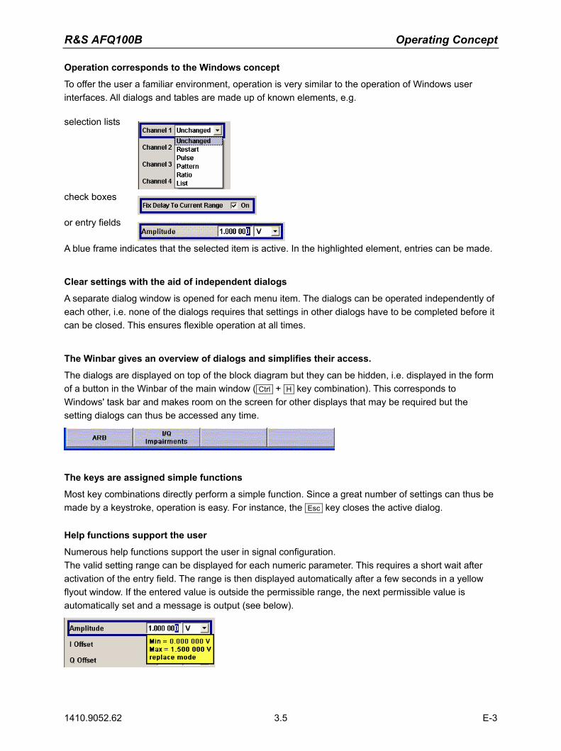
R&S AFQ100B Operating Concept
1410.9052.62 3.5 E-3
Operation corresponds to the Windows concept
To offer the user a familiar environment, operation is very similar to the operation of Windows user interfaces. All dialogs and tables are made up of known elements, e.g. selection lists
check boxes
or entry fields
A blue frame indicates that the selected item is active. In the highlighted element, entries can be made.
Clear settings with the aid of independent dialogs
A separate dialog window is opened for each menu item. The dialogs can be operated independently of each other, i.e. none of the dialogs requires that settings in other dialogs have to be completed before it can be closed. This ensures flexible operation at all times.
The Winbar gives an overview of dialogs and simplifies their access.
The dialogs are displayed on top of the block diagram but they can be hidden, i.e. displayed in the form of a button in the Winbar of the main window ( Ctrl + H key combination). This corresponds to Windows' task bar and makes room on the screen for other displays that may be required but the setting dialogs can thus be accessed any time.
The keys are assigned simple functions
Most key combinations directly perform a simple function. Since a great number of settings can thus be made by a keystroke, operation is easy. For instance, the Esc key closes the active dialog.
Help functions support the user
Numerous help functions support the user in signal configuration. The valid setting range can be displayed for each numeric parameter. This requires a short wait after activation of the entry field. The range is then displayed automatically after a few seconds in a yellow flyout window. If the entered value is outside the permissible range, the next permissible value is automatically set and a message is output (see below).

Operating Concept R&S AFQ100B
1410.9052.62 3.6 E-3
Context-sensitive online help for each parameter can be called with the F1 key: Each help page is part of a comprehensive online help function which can be called by means of an index, a content tree or the Previous / Next buttons.
Messages indicate the current instrument state
A great variety of different messages such as status messages, error messages, warnings or information are displayed in the header field of the screen. With the aid of the Ctrl + I key combination, help pages can be called for most of the messages. They provide background information on the message and indicate operating steps that may be required. All messages are explained in the online help which can be called with the F1 key.
Automatically Launching a Program or a Command File
RSAutoLaunch is a program which handles messages of the operating system which are sent when the user plugs in or removes devices such as drives or USB memory sticks. The program will start executable files which are automatically detected. After plugging in an USB memory stick, the instrument looks for executable or command files and processes them immediately. Depending on the kind of file found the instrument performs the following:
file action
Autoexec.exe start (asynchronous), R&S service use only
Autoexec.cmd start (synchronous), R&S service use only
Autoexec.bat start (synchronous), R&S service use only
Autoexec.iec send, i.e. executing GPIB commands The instrument will process remote control commands saved in an ASCII text file named Autoexec.iec on an USB memory stick. By launching such a command file, the user can test GPIB commands without connecting a control PC.
NOTICE Destruction hazard!
Starting executables other than autoexec.iec might destruct the instrument. We recommend to test GPIB commands using this function only.

R&S AFQ100B Display
1410.9052.62 3.7 E-3
Display
The external display shows the current modulation generator state and offers graphical elements for direct operation. It is divided into three sections:
The header along with an info line reports the current state with status, error and warning messages.
The block diagram shows the instrument configuration, the signal characteristic as well as the inputs and outputs used and permits interactive operation via graphical user interface. Active dialogs and graphs are displayed on top of the block diagram.
The winbar of the main window with labelled softkeys for dialog display.
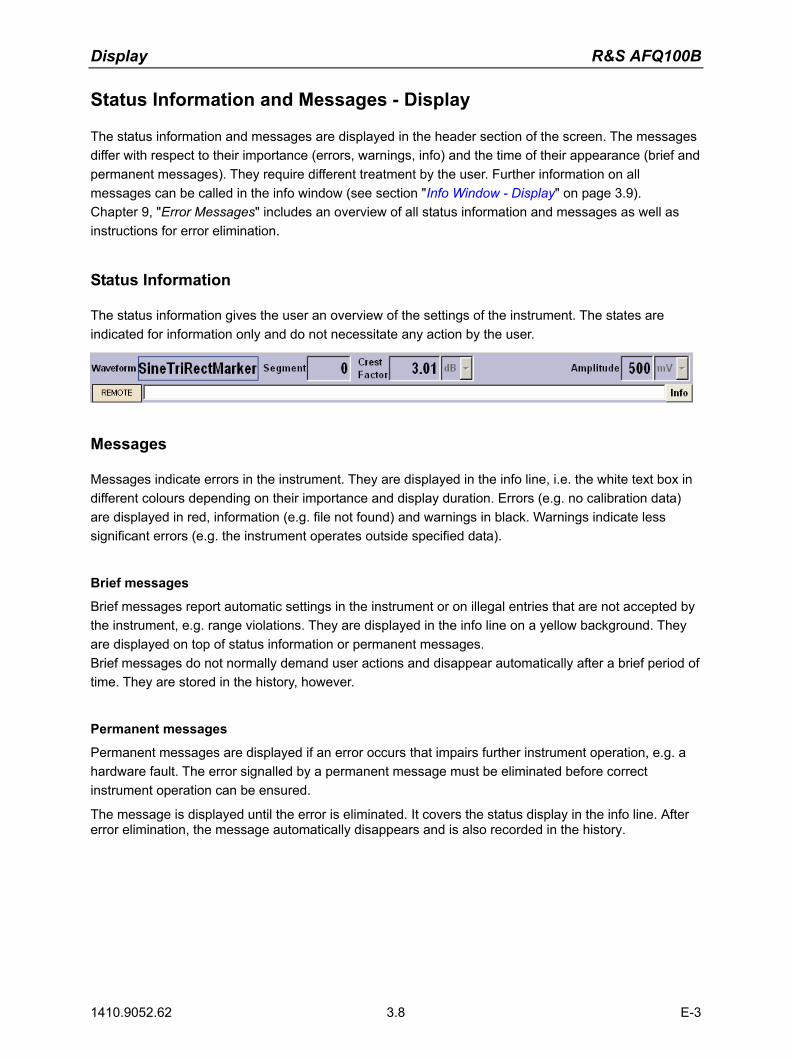
Display R&S AFQ100B
1410.9052.62 3.8 E-3
Status Information and Messages - Display
The status information and messages are displayed in the header section of the screen. The messages differ with respect to their importance (errors, warnings, info) and the time of their appearance (brief and permanent messages). They require different treatment by the user. Further information on all messages can be called in the info window (see section "Info Window - Display" on page 3.9). Chapter 9, "Error Messages" includes an overview of all status information and messages as well as instructions for error elimination.
Status Information
The status information gives the user an overview of the settings of the instrument. The states are indicated for information only and do not necessitate any action by the user.
Messages
Messages indicate errors in the instrument. They are displayed in the info line, i.e. the white text box in different colours depending on their importance and display duration. Errors (e.g. no calibration data) are displayed in red, information (e.g. file not found) and warnings in black. Warnings indicate less significant errors (e.g. the instrument operates outside specified data).
Brief messages
Brief messages report automatic settings in the instrument or on illegal entries that are not accepted by the instrument, e.g. range violations. They are displayed in the info line on a yellow background. They are displayed on top of status information or permanent messages. Brief messages do not normally demand user actions and disappear automatically after a brief period of time. They are stored in the history, however.
Permanent messages
Permanent messages are displayed if an error occurs that impairs further instrument operation, e.g. a hardware fault. The error signalled by a permanent message must be eliminated before correct instrument operation can be ensured.
The message is displayed until the error is eliminated. It covers the status display in the info line. After error elimination, the message automatically disappears and is also recorded in the history.
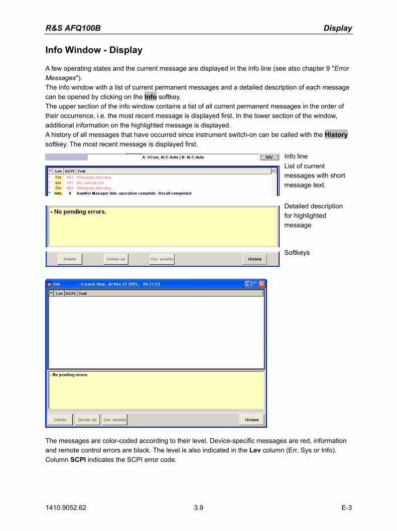
R&S AFQ100B Display
1410.9052.62 3.9 E-3
Info Window - Display
A few operating states and the current message are displayed in the info line (see also chapter 9 "Error Messages"). The info window with a list of current permanent messages and a detailed description of each message can be opened by clicking on the Info softkey. The upper section of the info window contains a list of all current permanent messages in the order of their occurrence, i.e. the most recent message is displayed first. In the lower section of the window, additional information on the highlighted message is displayed. A history of all messages that have occurred since instrument switch-on can be called with the History softkey. The most recent message is displayed first.
Info line List of current messages with short message text.
Detailed description for highlighted message
Softkeys
The messages are color-coded according to their level. Device-specific messages are red, information and remote control errors are black. The level is also indicated in the Lev column (Err, Sys or Info). Column SCPI indicates the SCPI error code.

Display R&S AFQ100B
1410.9052.62 3.10 E-3
With the aid of the softkey buttons, error messages can be cleared and a history of all messages called.
Delete Clears the highlighted message. This button is available only if the history of the messages is displayed. Remote-control command: (see "Delete All")
Delete All Clears all messages. This button is available only if the history of the messages is
displayed.
Remote-control command: SYST:ERR:ALL
Delete Vol. Clears all brief messages. This button is available only if the history of the
messages is displayed.
Remote-control command: History Calls the list of all messages that have occurred since instrument switch-on. The
most recent messages are displayed at the top of the list. When the button is pressed again, the list of current messages is displayed.
Remote-control command: :SYST:ERR? or :STAT:QUE? (Each time a SYSTem:ERRor? or :STATus:QUEue? query is sent, the oldest entry in the error queue is returned and at the same time cleared in the list).
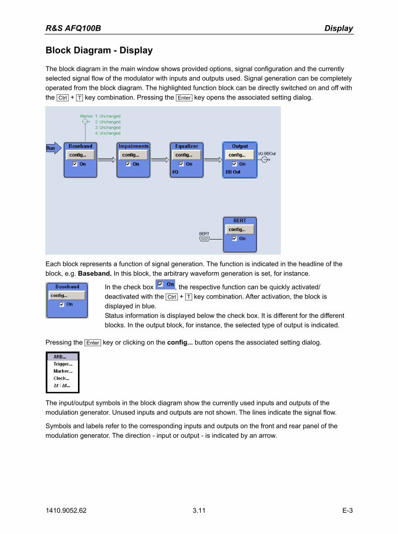
R&S AFQ100B Display
1410.9052.62 3.11 E-3
Block Diagram - Display
The block diagram in the main window shows provided options, signal configuration and the currently selected signal flow of the modulator with inputs and outputs used. Signal generation can be completely operated from the block diagram. The highlighted function block can be directly switched on and off with the Ctrl + T key combination. Pressing the Enter key opens the associated setting dialog.
Each block represents a function of signal generation. The function is indicated in the headline of the block, e.g. Baseband. In this block, the arbitrary waveform generation is set, for instance.
In the check box , the respective function can be quickly activated/ deactivated with the Ctrl + T key combination. After activation, the block is displayed in blue. Status information is displayed below the check box. It is different for the different blocks. In the output block, for instance, the selected type of output is indicated.
Pressing the Enter key or clicking on the config... button opens the associated setting dialog.
The input/output symbols in the block diagram show the currently used inputs and outputs of the modulation generator. Unused inputs and outputs are not shown. The lines indicate the signal flow.
Symbols and labels refer to the corresponding inputs and outputs on the front and rear panel of the modulation generator. The direction - input or output - is indicated by an arrow.

Display R&S AFQ100B
1410.9052.62 3.12 E-3
Example:
The symbols indicate the outputs for the analog I and Q signal on the instrument front panel.
The symbols indicate the outputs for the analog I and Q signal on the instrument front panel.
The marker characteristics are listed next to the marker symbol of the active markers. Symbols and lines are displayed in different colours depending on their function.
The baseband signal is indicated by a three line arrow, the I- and Q-components of the signal by a single-line arrow.
Black is used for the generated signal. Green is used for control signals.
Winbar and Softkeys - Display
The Winbar with eight buttons is displayed below the block diagram. Labelled buttons represent open dialogs, the label indicates the dialog. If several dialogs are open, the button of the currently active dialog is displayed in a lighter colour. The buttons also assign functions to the softkeys of the next lower level for front-panel operation. Up to eight dialogs may be open simultaneously. When the ninth dialog is opened, the dialog that was opened first is automatically closed.
Some dialogs assign dialog-specific functions to the front-panel softkeys by way of the dialog buttons. Any of the open dialogs can be activated either with the respective button in the Winbar or the front-panel softkey. In combination with the keys for dialog operation ( Esc , Alt + ... the underscored character of the name in the windows tas pane and the cursor keys), convenient dialog operation can be ensured. Dialog operation is described in section "Dialog Operation" on page 3.20.

R&S AFQ100B Display
1410.9052.62 3.13 E-3
Menu Structure - Display
The parameters are set in dialog boxes. Dialogs are called either via the function blocks in the diagram or in the windows menus. The dialogs are displayed on top of the block diagram. If the dialog buttons assign dialog-specific functions to the softkeys, the Winbar is hidden.
This section describes the dialog structure. Dialog operation is described in section "Dialog Operation" on page 3.20, the setting of parameters in section "Setting Parameters" on page 3.16. The dialogs are in Windows format. They differ in details depending on their function but they consist of the same main elements.
Dialog header
The header line contains the name of the dialog and the buttons for minimizing and closing the dialog. The buttons can be operated with the mouse. For operation from the external key board, the key combnation Alt + ... the underscored character, the cursor keys and the Esc key can be used.
The remaining dialog area is variable and comprises various fields for setting parameters.
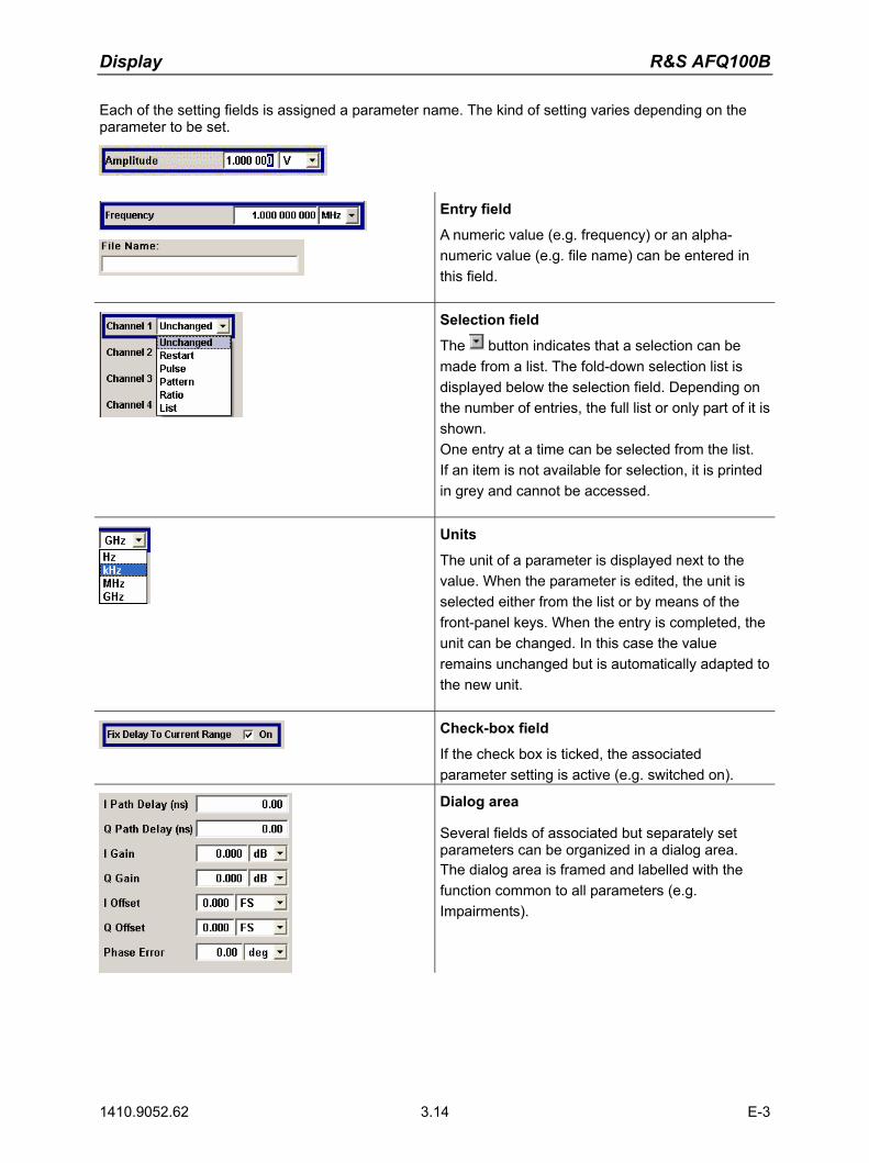
Display R&S AFQ100B
1410.9052.62 3.14 E-3
Each of the setting fields is assigned a parameter name. The kind of setting varies depending on the parameter to be set.
Entry field
A numeric value (e.g. frequency) or an alpha-numeric value (e.g. file name) can be entered in this field.
Selection field
The button indicates that a selection can be made from a list. The fold-down selection list is displayed below the selection field. Depending on the number of entries, the full list or only part of it is shown. One entry at a time can be selected from the list. If an item is not available for selection, it is printed in grey and cannot be accessed.
Units
The unit of a parameter is displayed next to the value. When the parameter is edited, the unit is selected either from the list or by means of the front-panel keys. When the entry is completed, the unit can be changed. In this case the value remains unchanged but is automatically adapted to the new unit.
Check-box field
If the check box is ticked, the associated parameter setting is active (e.g. switched on).
Dialog area
Several fields of associated but separately set parameters can be organized in a dialog area. The dialog area is framed and labelled with the function common to all parameters (e.g. Impairments).

R&S AFQ100B Display
1410.9052.62 3.15 E-3
Tables
Tables are made up of a header, which normally contains the column labels, and lines containing the text.
Graphical display
Graphical displays show signal characteristics, this chart plots user input of the equalizer. AFQ 100 A compensates these distortions.
Buttons
The buttons either trigger a single action (e.g. Off), or call the next dialog level (to be identified by 3 dots, e.g. Edit Data...). Some dialogs contain buttons that assign a function to the front-panel softkey below. These dialogs cover the Winbar.
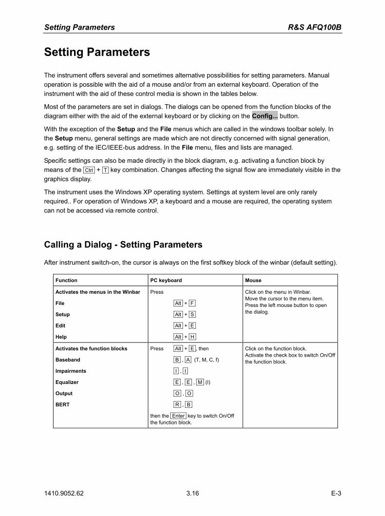
Setting Parameters R&S AFQ100B
1410.9052.62 3.16 E-3
Setting Parameters
The instrument offers several and sometimes alternative possibilities for setting parameters. Manual operation is possible with the aid of a mouse and/or from an external keyboard. Operation of the instrument with the aid of these control media is shown in the tables below.
Most of the parameters are set in dialogs. The dialogs can be opened from the function blocks of the diagram either with the aid of the external keyboard or by clicking on the Config... button.
With the exception of the Setup and the File menus which are called in the windows toolbar solely. In the Setup menu, general settings are made which are not directly concerned with signal generation, e.g. setting of the IEC/IEEE-bus address. In the File menu, files and lists are managed.
Specific settings can also be made directly in the block diagram, e.g. activating a function block by means of the Ctrl + T key combination. Changes affecting the signal flow are immediately visible in the graphics display.
The instrument uses the Windows XP operating system. Settings at system level are only rarely required.. For operation of Windows XP, a keyboard and a mouse are required, the operating system can not be accessed via remote control.
Calling a Dialog - Setting Parameters
After instrument switch-on, the cursor is always on the first softkey block of the winbar (default setting).
Function PC keyboard Mouse
Activates the menus in the Winbar
File
Setup
Edit
Help
Press
Alt + F
Alt + S
Alt + E
Alt + H
Click on the menu in Winbar. Move the cursor to the menu item. Press the left mouse button to open the dialog.
Activates the function blocks
Baseband
Impairments
Equalizer
Output
BERT
Press Alt + E , then
B , A (T, M, C, f)
I , I
E , E , M (I)
O , O
R , B
then the Enter key to switch On/Off the function block.
Click on the function block. Activate the check box to switch On/Off the function block.

R&S AFQ100B Setting Parameters
1410.9052.62 3.17 E-3
Selecting a Control Element - Setting Parameters
Control elements are always selected in the same way no matter whether a function block in the diagram, a menu in the menu tree, a parameter in the dialog or an entry in a list or table is concerned. An element is activated by means of the cursor. An active element is highlighted by a blue frame.
Function PC keyboard Mouse
Selects an element Select element by means of the cursor keys.
Click on the element.
Switching Parameters On/Off - Setting Parameters
A parameter can be activated and deactivated using a button or a check box. The Enter function of the different control media switches the highlighted element on or off (toggle
function). Colour and label of a button change, the check box is ticked or the tick is removed.
Function PC keyboard Mouse
Switches on/off Press the Enter key. Click on the check box or the button.
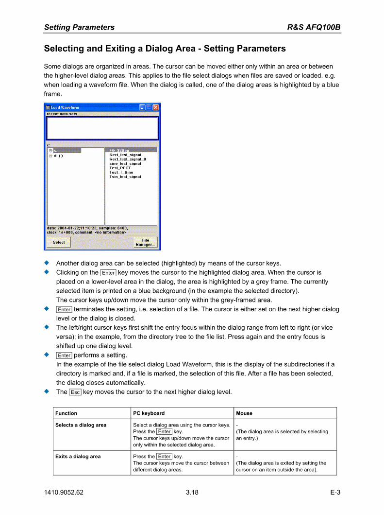
Setting Parameters R&S AFQ100B
1410.9052.62 3.18 E-3
Selecting and Exiting a Dialog Area - Setting Parameters
Some dialogs are organized in areas. The cursor can be moved either only within an area or between the higher-level dialog areas. This applies to the file select dialogs when files are saved or loaded. e.g. when loading a waveform file. When the dialog is called, one of the dialog areas is highlighted by a blue frame.
Another dialog area can be selected (highlighted) by means of the cursor keys. Clicking on the Enter key moves the cursor to the highlighted dialog area. When the cursor is
placed on a lower-level area in the dialog, the area is highlighted by a grey frame. The currently selected item is printed on a blue background (in the example the selected directory). The cursor keys up/down move the cursor only within the grey-framed area.
Enter terminates the setting, i.e. selection of a file. The cursor is either set on the next higher dialog level or the dialog is closed.
The left/right cursor keys first shift the entry focus within the dialog range from left to right (or vice versa); in the example, from the directory tree to the file list. Press again and the entry focus is shifted up one dialog level.
Enter performs a setting. In the example of the file select dialog Load Waveform, this is the display of the subdirectories if a directory is marked and, if a file is marked, the selection of this file. After a file has been selected, the dialog closes automatically.
The Esc key moves the cursor to the next higher dialog level.
Function PC keyboard Mouse
Selects a dialog area Select a dialog area using the cursor keys. Press the Enter key. The cursor keys up/down move the cursor only within the selected dialog area.
- (The dialog area is selected by selecting an entry.)
Exits a dialog area Press the Enter key. The cursor keys move the cursor between different dialog areas.
- (The dialog area is exited by setting the cursor on an item outside the area).

R&S AFQ100B Setting Parameters
1410.9052.62 3.19 E-3
Terminating Entries - Setting Parameters
Variations by means of the cursor keys are immediately set, e.g. delay settings. All other parameter settings have to be confirmed by a pressing the Enter key or one of the unit key combinations. Some settings require additional confirmation. This is the case when it is useful to first enter a few values and to confirm them together. All settings of instrument functions that can be switched on and off are calculated and effective only after this function has been switched on. Function PC keyboard Mouse
Accepts value immediately Vary the value with the up/down cursor keys.
-
Confirms entries Press the Enter key
or one of the key combinations
Alt + F9 / + F10 / + F11 / + F12 .
Exit entry field.
Confirms entries in the dialogs with the Accept button.
Select Accept button with the cursor keys and press Enter .
Click on Accept button.
Sets the entries in the instrument If the instrument function is active, the new value is immediately calculated and set.
If the instrument function is not active, the new, confirmed value is calculated and set only when the function is switched on.
(see keyboard)
Restoring the Previous Value - Setting Parameters
Parameter variations with the cursor keys are immediately set and therefore not reversible. Normally, values cannot be restored also in the case of mouse control because no explicit confirmation is required in this case and entries are automatically confirmed when the entry or selection field is exited.

Dialog Operation R&S AFQ100B
1410.9052.62 3.20 E-3
Dialog Operation
Dialogs are operated with the aid of the Winbar buttons and with key combinations. The Ctrl + H key combination minimizes an active dialog. It is displayed in the form of a Winbar
button. The Ctrl + F1 to F8 key combinations maximize the corresponding dialog. The Ctrl + G key combination closes an active dialog. The softkeys call or close the associated dialog and set the cursor in the dialog.
Note: The Esc key also closes the active dialog if the cursor is at the highest dialog level.
Function PC keyboard Mouse
Displays a dialog in the foreground Press Ctrl + F1 to F8 Click on the respective button in the Winbar.
Minimizes an active dialog Press Ctrl + H Click on the button in the header line.
Closes an active dialog Press Ctrl + G Click on the button in the header line.
Hides all dialogs Press Ctrl + D -

R&S AFQ100B Editors
1410.9052.62 3.21 E-3
Editors
The GUI provides user-friendly editors for defining data lists. The lists are saved to files and may thus have any length. The file name of the lists and the directory to which the files are saved are user-selectable. The file prefix is different for each list type and is permanently assigned by the system (see section "File Management" on page 3.25).
Equalizer List Editor
The Equalizer menus provide the editor for defining the frequency/gain/phase value triplets. The associated button Edit Data... calls up the list editor to edit the current list whose file name is displayed.
To select another one, click on List Data..., then Select List... or New List... which will open the Select List or the New List dialog, respectively.
The selected list is displayed. If no list has been selected, a blank list of only one row is displayed.
The value pairs are entered in the Frequency/Hz, Gain/dB, and Phase/deg table columns. A blank row is inserted at the end of the list.
New rows can be inserted anywhere in the table by means of the Insert/Fill Row(s)... button. After the list has been edited, i.e. changed, it can be saved under its current name by means of the
Save button, or under a new name by means of the Save as... button. Only complete value pairs are taken into consideration; rows containing an entry in only one column are ignored.
An existing list can be edited in the insert or overwrite mode. A new list can be created under a new name either by generating a blank file in the file select menu
(see section "File Management" on page 3.25) or by changing an existing list which will then be saved under a new name.

Editors R&S AFQ100B
1410.9052.62 3.22 E-3
Function PC keyboard Mouse
Call up editor. The cursor marks the first row of the Frequency/Hz column.
Mark the Edit Data... button in the individual dialog and press the Enter key.
Click on the Edit Data... button in the individual dialog.
Enter value. Use the numeric keys to enter the value and terminate the entry by pressing the Enter key.
-
Change column. Press the left/right cursor keys. Click on the cell.
Change row. Use the up/down cursor keys to mark the row. Click on the cell.
Select row.
The cursor moves to the selected row.
Mark the GoTo button and press the Enter key.
Use the numeric keys to enter the row index and terminate the entry by pressing the Enter key.
Click on the cell.
Insert row.
A row is inserted above the currently marked row. If no row has been selected, a row is inserted at the beginning of the list.
Select the row above which the new row is to be inserted.
Mark the Insert Row(s) button and press the Enter key.
Click the row above which the new row is to be inserted.
Click on the Insert Row(s) button.
Save list under a new name. Mark the Save as.. button and press the Enter key.
Enter the file name in the menu Create List File Which Name? and select the directory (see section "Select / Save Lists - File Management" on page 3.28)
Double-click on the Save as... button.
Enter the file name in the menu Create List File Which Name? and select the directory (see section "Select / Save Lists - File Management" on page 3.28)
Save list under the same name.
Mark the Save button and press the Enter key.
Double-click on the Save button.
Create new list. Mark the List Data ... button and press the Enter key.
Mark the menu item New List and press the Enter key.
Select the directory and enter the file name in the menu New List (see section "Select / Save Lists - File Management" on page 3.28).
Double-click on the List Data... button.
Double-click on New List.
Select the directory and enter the file name in the menu New List (see section "Select / Save Lists - File Management" on page 3.28).
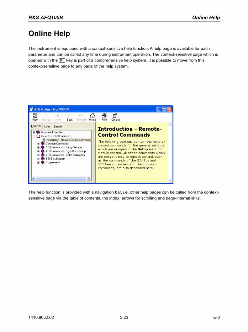
R&S AFQ100B Online Help
1410.9052.62 3.23 E-3
Online Help
The instrument is equipped with a context-sensitive help function. A help page is available for each parameter and can be called any time during instrument operation. The context-sensitive page which is opened with the F1 key is part of a comprehensive help system. It is possible to move from this context-sensitive page to any page of the help system.
The help function is provided with a navigation bar, i.e. other help pages can be called from the context-sensitive page via the table of contents, the index, arrows for scrolling and page-internal links.
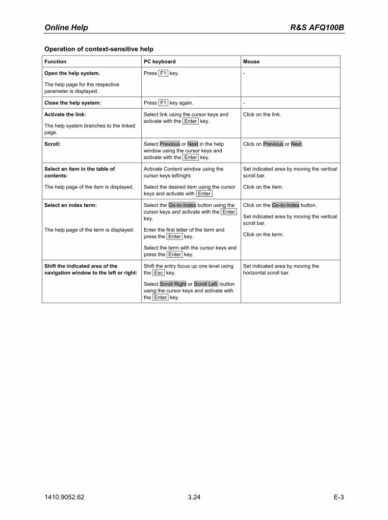
Online Help R&S AFQ100B
1410.9052.62 3.24 E-3
Operation of context-sensitive help
Function PC keyboard Mouse
Open the help system.
The help page for the respective parameter is displayed.
Press F1 key. -
Close the help system: Press F1 key again. -
Activate the link:
The help system branches to the linked page.
Select link using the cursor keys and activate with the Enter key.
Click on the link.
Scroll: Select Previous or Next in the help window using the cursor keys and activate with the Enter key.
Click on Previous or Next.
Select an item in the table of contents:
The help page of the item is displayed.
Activate Content window using the cursor keys left/right.
Select the desired item using the cursor keys and activate with Enter .
Set indicated area by moving the vertical scroll bar.
Click on the item.
Select an index term:
The help page of the term is displayed.
Select the Go-to-Index button using the cursor keys and activate with the Enter key.
Enter the first letter of the term and press the Enter key.
Select the term with the cursor keys and press the Enter key.
Click on the Go-to-Index button.
Set indicated area by moving the vertical scroll bar.
Click on the term.
Shift the indicated area of the navigation window to the left or right:
Shift the entry focus up one level using the Esc key.
Select Scroll Right or Scroll Left -button using the cursor keys and activate with the Enter key.
Set indicated area by moving the horizontal scroll bar.

R&S AFQ100B File Management
1410.9052.62 3.25 E-3
File Management
The instrument uses files to save all instrument data, i.e. system and user data. The user data includes saved instrument settings, data for the different digital standards, lists for the List mode and the user correction as well as the waveforms for multcarrier CW generation and the arbitrary waveform generator. The files are stored on the hard disk of the instrument. Drive D:\ can be used to save user-defined data; any directory structure can be created on D:\. Some default directories are predefined, but can be changed at any time. The C:\ drive is a protected system drive. The files on this drive contain data that must not be changed. Therefore, this drive should not be accessed, since reconstruction of the system partition will lead to data loss. To prevent inadvertent deletion or overwriting of system files, this drive is not specified in the file menus. It can be accessed if a protection level (see protection level, Setup menu) is revoked. Files can be exchanged either via a memory stick or a connected network. A memory stick is connected to the USB interface and is assigned to the next free drive. In the case of a connected network, all network drives that can be accessed are available (see chapter 1, section "Connecting the R&S AFQ to a Network (LAN)" on page 1.26).
The user data can be roughly divided into four data types:
1. Instrument Settings 2. Lists 3. Complex modulation and control data 4. Waveforms Depending on the data type, a file can either be selected, created or it can be selected and saved. The files are differentiated according to their extensions; each type of file is assigned a specific file content. The extension is usually of no consequence to the user since access to the files occurs in the individual dialogs where only the relevant type of file is available.. 1. Settings of the instrument can be loaded and saved in the File menu (see section "Select / Save
Instrument Settings - File Management" on page 3.26). 2. Lists, e.g. user correction lists, can be loaded in the Select List window. Lists can be generated
either externally or internally. For internal generation, a new list must be created in the window New List which will then be edited in the list editor (see section "Editors" on page 3.21).
3. Complex modulation and control data can be loaded in the Select List window. It can be generated either externally or internally. For internal generation, a new list must be created in the New List window which will then be edited in the data and control list editor.
4. Waveforms are generated externally (e.g. by means of the R&S WinIQSIM program that is supplied together with the instrument) and can be loaded in the Arbitrary Waveform Generation (ARB) menu by clicking on the Load Waveform... button.
Each of the windows Select List and Load Waveform contain buttons/softkeys for the Select and File Manager functions. Internally generated lists can be stored by clicking on the Save button in the New List window. Clicking on the File Manager... button opens the File Manager window for managing all files (see section "File Manager" on page 3.30).
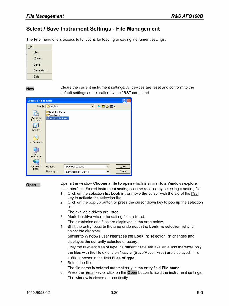
File Management R&S AFQ100B
1410.9052.62 3.26 E-3
Select / Save Instrument Settings - File Management
The File menu offers access to functions for loading or saving instrument settings.
New Clears the current instrument settings. All devices are reset and conform to the default settings as it is called by the *RST command.
Open ... Opens the window Choose a file to open which is similar to a Windows explorer user interface. Stored instrument settings can be recalled by selecting a setting file. 1. Click on the selection list Look in: or move the cursor with the aid of the Tab
key to activate the selection list. 2. Click on the pop-up button or press the cursor down key to pop up the selection
list. The available drives are listed.
3. Mark the drive where the setting file is stored. The directories and files are displayed in the area below.
4. Shift the entry focus to the area underneath the Look in: selection list and select the directory. Similar to Windows user interfaces the Look in: selection list changes and displayes the currently selected directory. Only the relevant files of type Instrument State are available and therefore only the files with the file extension *.savrcl (Save/Recall Files) are displayed. This suffix is preset in the field Files of type.
5. Select the file. The file name is entered automatically in the entry field File name.
6. Press the Enter key or click on the Open button to load the instrument settings.The window is closed automatically.

R&S AFQ100B File Management
1410.9052.62 3.27 E-3
Save Saves the current instrument settings. If the instrument works with loaded settings the current changes will overwrite the setttings in the file. File name and path cannot be entered. If the instrument does not work with loaded settings the function Save as ... will be called automatically.
Save as ... Opens the window Choose a filename to save under, a Windows explorer user interface which is similar to the Choose a file to open window (see above). The instrument settings can be stored in a setting file. 1. Click on the selection list Save in: or move the cursor with the aid of the Tab
key to activate the selection list. 2. Click on the pop-up button or press the cursor down key to pop up the selection
list. The available drives are listed.
3. Mark the drive where the setting file has to be stored. The directories and files are displayed in the area below.
4. Shift the entry focus to the area underneath the Save in: selection list and select the directory. Similar to Windows user interfaces the Save in: selection list changes and displayes the currently selected directory.
Note: If a file is highlighted the file name is entered automatically in the entry field File name:. Then the current settings will overwrite the setttings in the file.
5. Move the cursor to the entry field File name: and enter the file name. The instrument assigns the file extension *.savrcl (Save/Recall Files) to all files of type Instrument State automatically. The extension cannot be entered.
6. Press the Enter key or click on the Save button to save the instrument settings.The window is closed automatically.
Exit Shuts down the windows operating system. The current settings are stored on the hard disk before the system is shut down.
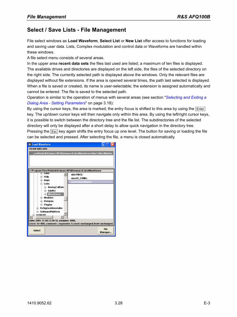
File Management R&S AFQ100B
1410.9052.62 3.28 E-3
Select / Save Lists - File Management
File select windows as Load Waveform, Select List or New List offer access to functions for loading and saving user data. Lists, Complex modulation and control data or Waveforms are handled within these windows. A file select menu consists of several areas. In the upper area recent data sets the files last used are listed; a maximum of ten files is displayed. The available drives and directories are displayed on the left side, the files of the selected directory on the right side. The currently selected path is displayed above the windows. Only the relevant files are displayed without file extensions. If the area is opened several times, the path last selected is displayed. When a file is saved or created, its name is user-selectable; the extension is assigned automatically and cannot be entered. The file is saved to the selected path. Operation is similar to the operation of menus with several areas (see section "Selecting and Exiting a Dialog Area - Setting Parameters" on page 3.18): By using the cursor keys, the area is marked; the entry focus is shifted to this area by using the Enter key. The up/down cursor keys will then navigate only within this area. By using the left/right cursor keys, it is possible to switch between the directory tree and the file list. The subdirectories of the selected directory will only be displayed after a short delay to allow quick navigation in the directory tree. Pressing the Esc key again shifts the entry focus up one level. The button for saving or loading the file can be selected and pressed. After selecting the file, a menu is closed automatically.

R&S AFQ100B File Management
1410.9052.62 3.29 E-3
Select Loads user data. 1. Select the drive and the directory in the left window.
The available files are listed in the right window. 2. Press the Enter key or click on the Select button to load the file data.
Save Saves new entries of user data. For editing user data see "Equalizer List Editor" on page 3.21). The file name of the lists and the directory to which the files have to be saved are user-selectable. The file extension is different for each list type and is assigned automatically by the system (see "File Manager" on page 3.30). The extension cannot be entered. 1. Select the drive and the directory in the left window. 2. Move the cursor to the entry field File name: and enter the file name. 3. Press the Enter key or click on the Save button to create the new data file.
Note: If a file is highlighted the file name is entered automatically in the entry field File name:. Then the current data will overwrite the data in the file.
File Management R&S AFQ100B
1410.9052.62 3.30 E-3
File Manager
The File Manager allows general file management such as copying, shifting, renaming and deleting files as well as generating new directories. Thus, also externally created files, for example waveforms created by using the R&S WinIQSIM2 program, can be saved to the instrument by copying them from a memory stick or a network to the internal hard disk. The File Manager can be called up via the File Manager... button in any menu to which files can be saved. In the upper area File Type the File Manager allows the type file selection to be displayed. This can be used to process either all files (all files (*:*) selection) or a specific selection of files (e.g. waveforms (*.wv) selection). The table at the end of this section contains a list of the file types. The available drives and directories are displayed on the left side, the files of the selected directory on the right side. The currently selected path is displayed above the windows. If the area is opened several times, the path last selected is displayed. Unlike the file select windows, the File Manager displays the full file names including the extensions. The buttons/softkeys trigger the associated actions such as copying, shifting or deleting the marked files. A new directory can be created in the level below the marked directory. Operation is similar to the operation of menus with several areas (see section "Selecting and Exiting a Dialog Area - Setting Parameters" on page 3.18): By using the cursor keys, the area is marked; the entry focus is shifted to this area by using the Enter key. The up/down cursor keys will then navigate only within this area. By using the left/right cursor keys, it is possible to switch between the directory tree and the file list. The subdirectories of the selected directory will only be displayed after a short delay to allow quick navigation in the directory tree. Pressing the Esc key again shifts the entry focus up one level. The buttons/softkeys can be selected and activated.
Shift file:
Mark file and then press the Cut button. Mark the directory to which the file is to be shifted and then click on the Paste button. If the target directory already contains a file with the same name, a confirmation query is displayed to confirm overwriting of this file.
Copy file:
Mark file and then press the Copy button. Mark the directory to which the file is to be copied and then click on the Paste button. If the target directory already contains a file with the same name, a confirmation query is displayed to confirm overwriting of this file.
Rename file:
Mark file and then press the Rename button. An entry window for entering the new file name opens. Enter the name and press the Enter key. If a file with the same name already exists, a confirmation query is displayed to confirm overwriting of this file.
Delete file:
Mark file and then press the Delete button. Prior to deletion, a confirmation query is displayed which the user must confirm for this file to be deleted.
Create new directory:
Mark drive or directory level where the new directory is to be created and then press the Create New Directory button. An entry window for entering the directory name opens. Enter the name and press the Enter key.
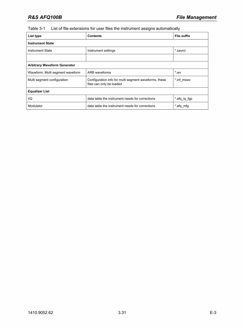
R&S AFQ100B File Management
1410.9052.62 3.31 E-3
Table 3-1 List of file extensions for user files the instrument assigns automatically
List type Contents File suffix
Instrument State
Instrument State Instrument settings *.savrcl
Arbitrary Waveform Generator
Waveform, Multi segment waveform ARB waveforms *.wv
Multi segment configuration Configuration info for multi segment waveforms, these files can only be loaded
*.inf_mswv
Equalizer List
I/Q data table the instrument needs for corrections *.afq_iq_fgp
Modulator data table the instrument needs for corrections *.afq_mfg

R&S AFQ100B Contents "Remote Control Basics"
1410.9052.62 I-5.1 E-3
Contents - Chapter 5 "Remote Control Basics" 5 Remote Control - Basics ..............................................................5.1
Introduction - Remote Control Basics............................................................ 5.1 Getting Started .............................................................................................. 5.3 Switchover to Remote Control....................................................................... 5.5
Remote Control via IEC/IEEE Bus ................................................... 5.5 Remote Control via LAN Interface.................................................... 5.8 Remote Control via USB Interface ................................................. 5.14
Interface and Device Messages .................................................................. 5.15 Interface Messages ........................................................................ 5.15 Device Messages (Commands and Device Responses)............... 5.15
SCPI Command Structure and Syntax........................................................ 5.17 Structure of a Command Line ........................................................ 5.19 Responses to Queries.................................................................... 5.20 Parameters ..................................................................................... 5.20 Overview of Syntax Elements ........................................................ 5.23
Instrument Model and Command Processing ............................................. 5.24 Input Unit ........................................................................................ 5.24 Command Recognition................................................................... 5.25 Data Base and Instrument Hardware............................................. 5.25 Status Reporting System................................................................ 5.25 Output Unit ..................................................................................... 5.26 Command Sequence and Command Synchronization .................. 5.26
Status Reporting System............................................................................. 5.27 Overview of the Status Register..................................................... 5.27 Status Byte (STB) and Service Request Enable Register (SRE) .. 5.28 IST-Flag and Parallel Poll Enable Register (PPE) ......................... 5.28 Event Status Register (ESR) and
Event Status Enable Register (ESE)............................................. 5.29 Application of the Status Reporting System................................... 5.30 Reset Values of the Status Reporting Systems ............................. 5.32
Remote Control Hardware Interfaces.......................................................... 5.33 IEC/IEEE Bus Interface .................................................................. 5.33 LAN Connector ............................................................................... 5.36


R&S AFQ100B Remote Control - Basics
1410.9052.62 5.1 E-3
5 Remote Control - Basics
Introduction - Remote Control Basics
This chapter provides: Instructions on how to set up the modulation generator for remote control operation. A general introduction to remote control of programmable instruments. This includes the description
of the command structure and syntax according to the SCPI standard, the description of command execution and of the status registers.
A description of the remote control interfaces. In chapter 6, all remote control functions are described in detail. All commands and their parameters are listed by alphabetical order in the command list at the end of chapter 6. The instrument is equipped with the following interfaces for remote control:
IEC/IEEE bus interface according to standard IEC 625.1/IEEE 488.2 LAN interface: the network card uses 10/100/1000Mbps Ethernet IEEE 802.3u; the protocol is
based on the VXI-11 standard. USB interface (slave USB)
The master USB interfaces can be used for a firmware update and for connecting peripherals such as mouse and keyboard.
The connectors are located at the rear of the instrument and permit a connection to a controller for remote control either directly or via a local area network (LAN). The remote control interfaces and their interface functions are described in section "Remote Control Hardware Interfaces", on page 5.33. SCPI (Standard Commands for Programmable Instruments) commands are used for remote control. Commands that are not taken from the SCPI standard follow the SCPI syntax rules. The instrument supports the SCPI version 1999. The SCPI standard is based on standard IEEE 488.2 and aims at the standardization of instrument control commands, error handling and the status registers. The tutorial "Automatic Measurement Control � A tutorial on SCPI and IEEE 488.2" from John M. Pieper (R&S order number 0002.3536.00) offers detailed information on concepts and definitions of SCPI. Not all of the commands supported by the instrument are taken from the SCPI standard, but their syntax follows SCPI rules. This section assumes basic knowledge of programming and operation of the controller. A description of the interface commands can be obtained from the relevant manuals. The requirements that the SCPI standard places on command syntax, error handling and configuration of the status registers are explained in detail in the following sections. Tables provide a fast overview of the bit assignment in the status registers. The tables are supplemented by a comprehensive description of the status registers. The program examples for IEC/IEEE-bus programming are all written in VISA. VISA is a standardized software interface library providing input and output functions to communicate with instruments. The I/O channel (LAN, GPIB�) is selected at initialization time by means of a channel-specific resource string. For more information about VISA refer to that user documentation.

Remote Control - Basics R&S AFQ100B
1410.9052.62 5.2 E-3
The programming examples for remote control are all written in Microsoft® VISUAL BASIC®. Access to the VISA functions require the declaration of the functions and constants prior to their use in the project. This can be accomplished either by adding the modules VISA32.BAS and VPPTYPE.BAS or a reference to the VISA32.DLL to the project.
The modules visa32.bas and vpptype.bas can be found in the <VXIpnpPath>\WinNT\include (typically C:\VXIpnp\WinNt\include).
Note: Manual control is designed for maximum possible operating convenience. In contrast, the priority of remote control is the predictability of the device status. Therefore, control programs should always define an initial device status (e.g. by the command *RST) and then implement the required settings. Drivers for the generator, e.g. IVI-COM and LabVIEW drivers, are available in the download area of the R&S product website (http://www.rohde-schwarz.com/product/AFQ100).

R&S AFQ100B Remote Control - Basics
1410.9052.62 5.3 E-3
Getting Started
The short and simple operating sequence given below permits fast putting into operation of the instrument and setting of its basic functions. As a prerequisite, the IEC/IEEE-bus address, which is factory-set to 28, must not have been changed. 1. Connect instrument and controller using IEC/IEEE-bus cable and switch them on. 2. Write and start the following program on the controller:
Dim defaultRM As ViSession
Dim status As ViStatus
Dim vi As ViSession
Dim Cmd As String
Dim retCount As ViUInt32
Dim ErrorDescription As String * VI_FIND_BUFLEN
status = viOpenDefaultRM(defaultRM) 'Open default resource manager
If status <> VI_SUCCESS Then GoTo ErrorExit:
status = viOpen(defaultRM, "GPIB::6::INSTR", 0, 5000, vi)
'Open connection to instrument
If status <> VI_SUCCESS Then GoTo ErrorExit:
Cmd = "*RST;*CLS;*WAI"
status = viWrite(vi, Cmd, Len(Cmd), retCount)
'Reset instrument and clear status registers
If status <> VI_SUCCESS Then GoTo ErrorExit:
Cmd = "OUTP:STAT ON"
status = viWrite(vi, Cmd, Len(Cmd), retCount)
'Switch on output
If status <> VI_SUCCESS Then GoTo ErrorExit:
Cmd = "WAV:SEL 'C:\Program Files\Rohde&Schwarz\AFQFirmware\Lists\ Waveforms\sine10kHz.wv'"
status = viWrite(vi, Cmd, Len(Cmd), retCount)
'Load waveform file
If status <> VI_SUCCESS Then GoTo ErrorExit:
Cmd = "SOUR:STAT ON"
status = viWrite(vi, Cmd, Len(Cmd), retCount)
'Switch on generation of waveform file
If status <> VI_SUCCESS Then GoTo ErrorExit:

Remote Control - Basics R&S AFQ100B
1410.9052.62 5.4 E-3
Exit Sub
ErrorExit:
viStatusDesc vi, status, ErrorDescription
MsgBox ErrorDescription The selected waveform signal is now applied at the default output of the instrument.
R&S AFQ100B Remote Control - Basics
1410.9052.62 5.5 E-3
Switchover to Remote Control
On power-on, the instrument is always in the manual operating state and can be operated via external mouse, keyboard and monitor. In case of remote control via the IEC/IEEE bus, the instrument is set to remote control (REMOTE status) by means of an addressed command. With remote control via Ethernet, remote control is not automatically set by means of a command. The instrument must be explicitly set to the REMOTE state, e.g. by sending the interface command >R (go to remote). In the REMOTE state, instrument control via external mouse, keyboard and monitor is disabled. Dialogs can be opened, however, e.g. to verify settings. Buttons and setting fields are displayed in gray and cannot be activated. REMOTE is displayed in the status line. The instrument remains in the REMOTE mode until local control is selected either manually with the Ctrl + Q key combination on the external keyboard or with the interface command >L via the remote-control interface. Switching from manual operation to remote control and vice versa does not affect the remaining instrument settings. In the remote control mode, an external mouse or keyboard that may be connected can be disabled with the keyboard lock command: :SYST:KLOC ON Dialogs cannot be opened in this case and switchover from remote control to manual operation is only possible by means of a remote-control command. Inadvertent switchover with the Ctrl + Q key combination is not possible in this case. Operation of the Ctrl + Q key combination alone can be disabled with interface command &LLO.
Remote Control via IEC/IEEE Bus
To be able to control the instrument via the IEC/IEEE bus, instrument and controller must be linked by an IEC/IEEE-bus cable. An IEC/IEEE-bus card, the card drivers and the program libraries for the programming language used must be provided in the controller. The controller must address the instrument with the set IEC/IEEE-bus address. The IEC/IEEE bus address of the instrument is factory-set to 6. It can be changed via IEC/IEEE bus with command SYSTem:COMMunicate:GPIB: ADDRess or manually in the Environment - GPIB dialog. Addresses 0 to 30 are permissible.
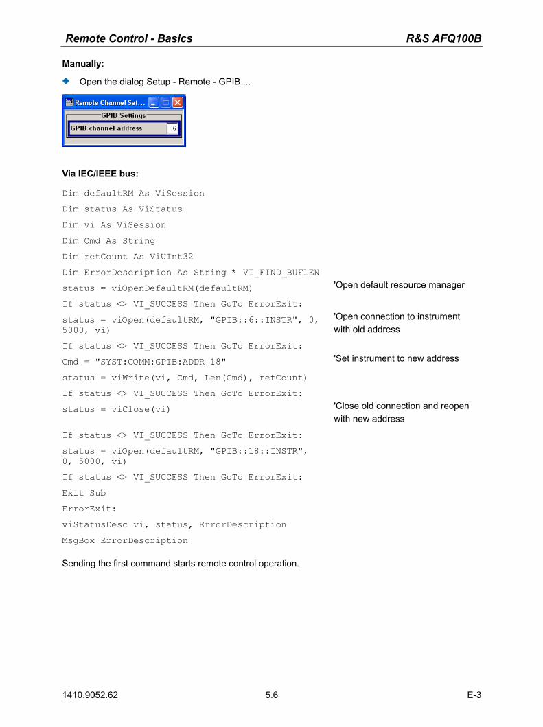
Remote Control - Basics R&S AFQ100B
1410.9052.62 5.6 E-3
Manually:
Open the dialog Setup - Remote - GPIB ...
Via IEC/IEEE bus:
Dim defaultRM As ViSession
Dim status As ViStatus
Dim vi As ViSession
Dim Cmd As String
Dim retCount As ViUInt32
Dim ErrorDescription As String * VI_FIND_BUFLEN
status = viOpenDefaultRM(defaultRM) 'Open default resource manager
If status <> VI_SUCCESS Then GoTo ErrorExit:
status = viOpen(defaultRM, "GPIB::6::INSTR", 0, 5000, vi)
'Open connection to instrument with old address
If status <> VI_SUCCESS Then GoTo ErrorExit:
Cmd = "SYST:COMM:GPIB:ADDR 18"
status = viWrite(vi, Cmd, Len(Cmd), retCount)
'Set instrument to new address
If status <> VI_SUCCESS Then GoTo ErrorExit:
status = viClose(vi) 'Close old connection and reopen with new address
If status <> VI_SUCCESS Then GoTo ErrorExit:
status = viOpen(defaultRM, "GPIB::18::INSTR", 0, 5000, vi)
If status <> VI_SUCCESS Then GoTo ErrorExit:
Exit Sub
ErrorExit:
viStatusDesc vi, status, ErrorDescription
MsgBox ErrorDescription Sending the first command starts remote control operation.
R&S AFQ100B Remote Control - Basics
1410.9052.62 5.7 E-3
Return to manual operation is possible via the front panel or the IEC/IEEE bus.
Manually:
Press the Ctrl + Q key combination.
Note: Before the transition, command processing must be completed as otherwise transition to remote control is performed immediately. The Ctrl + Q key combination can be disabled by the interface message &LLO (see section IEC/IEEE-Bus Interface Functions, on page 5.35) in order to prevent unintentional transition. In this case, transition to manual mode is only possible via the IEC/IEEE bus. The Ctrl + Q key combination can be enabled again by deactivating the REN line of the IEC/IEEE bus (see section IEC/IEEE-Bus Interface Functions, on page 5.35).
Via IEC/IEEE bus:
... status = viGpibControlREN(vi, VI_GPIB_REN_ADDRESS_GTL)
'Set instrument to manual operation
...

Remote Control - Basics R&S AFQ100B
1410.9052.62 5.8 E-3
Remote Control via LAN Interface
For remote control via a network, the PC and the instrument must be connected via the LAN interface to a common network with TCP/IP network protocol. Connection of the R&S AFQ to a network and the querying of a computer name is described in chapter 1, section Query Computer Name.
Note: In contrast to file transfer via LAN which requires only a partial permission (exception) in the firewall, remote control via LAN is possible only if the firewall is completely switched off. Therefore, the firewall settings for remote control differ from the firewall settings for file transfer (see following description).
Setting for Remote Control:
Start � Control Panel � Switch to Classic View � Windows Firewall � Off (not recommended)
NOTICE Risk of hostile users or programs! It is recommend to enable the Windows Firewall again after termination of remote control via LAN (setting On (recommended)) in order to protect the instrument from an attack of hostile users or programs via the net.

R&S AFQ100B Remote Control - Basics
1410.9052.62 5.9 E-3
Software for instrument control and the VISA program library must be installed on the controller. The instrument control is via the VXI-11 standard protocol. Only the IP address or the computer name is required for link setup. The IP address/computer name is part of the "resource name" used by the programs for identification and control of the instrument. The resource name has the form:
TCPIP::ipaddr::inst0::INSTR ipaddr has to be replaced by the IP address or the computer name of the instrument. For instance, if the instrument has the IP address 192.1.2.3, TCPIP::192.1.2.3::inst0::INSTR is the valid resource name. Specification of inst0 in the resource name is optional. In this example, also TCPIP::192.1.2.3::INSTR is therefore a valid resource name. A resource name with computer name could be TCPIP::RSAFQ100Bxxxxxx::INSTR, for instance. TCPIP designates the network protocol used and INSTR indicates that the VXI-11 protocol is used. If several instruments are connected to the network, each instrument has its own IP address and associated resource name. The controller identifies these instruments by means of the resource name. In the example below, the program 'Measurement & Automation Explorer' from National Instruments is used for setting up an Ethernet remote-control link. Link setup with this program is easy and first tests can be performed. The R&S AFQ is preconfigured for networks using DHCP (dynamic host configuration protocol). If this configuration is used, the computer name must be entered at the position of the IP address. It is also possible to assign a fixed IP address to the R&S AFQ (see chapter 1, section Configuring the R&S AFQ for Network Operation).
Setting up Control of the R&S AFQ in the 'Measurement & Automation Control' Program.
1. Start the program on the controller 2. Open the Create new menu with the right mouse key.

Remote Control - Basics R&S AFQ100B
1410.9052.62 5.10 E-3
3. Select TCP/IP Resource and open the next page of the Create new menu with the right mouse key.
4. Enter the IP address of the R&S AFQ and select VXI-11 Instrument
(the computer name may be entered instead).
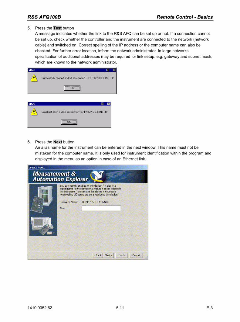
R&S AFQ100B Remote Control - Basics
1410.9052.62 5.11 E-3
5. Press the Test button A message indicates whether the link to the R&S AFQ can be set up or not. If a connection cannot be set up, check whether the controller and the instrument are connected to the network (network cable) and switched on. Correct spelling of the IP address or the computer name can also be checked. For further error location, inform the network administrator. In large networks, specification of additional addresses may be required for link setup, e.g. gateway and subnet mask, which are known to the network administrator.
6. Press the Next button.
An alias name for the instrument can be entered in the next window. This name must not be mistaken for the computer name. It is only used for instrument identification within the program and displayed in the menu as an option in case of an Ethernet link.
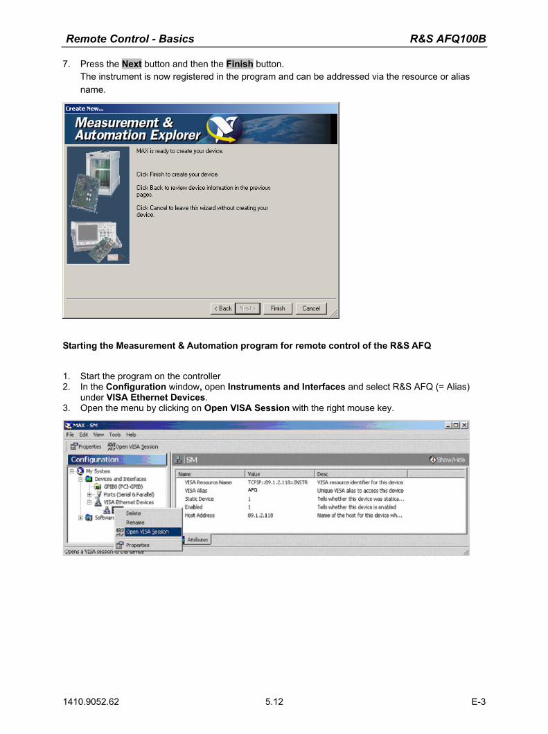
Remote Control - Basics R&S AFQ100B
1410.9052.62 5.12 E-3
7. Press the Next button and then the Finish button. The instrument is now registered in the program and can be addressed via the resource or alias name.
Starting the Measurement & Automation program for remote control of the R&S AFQ
1. Start the program on the controller 2. In the Configuration window, open Instruments and Interfaces and select R&S AFQ (= Alias)
under VISA Ethernet Devices. 3. Open the menu by clicking on Open VISA Session with the right mouse key.

R&S AFQ100B Remote Control - Basics
1410.9052.62 5.13 E-3
On the viWrite tab under Basic I/O commands can be sent to the instrument. Instrument responses are displayed on the viRead tab (for further program operation refer to the online help of the program).
Return to manual operation is possible either manually with the Ctrl + Q key combination on the external keyboard or via the LAN interface.
Manually:
Press the Ctrl + Q key combination.
Note: The Ctrl + Q key combination can be disabled by the universal command &LLO (see section VXI-11 Interface Messages, on page 5.39) in order to prevent unintentional transition. In this case, transition to manual mode is possible only via remote control. The Ctrl + Q key combination can be enabled again by the interface message &NREN (see section VXI-11 Interface Messages, on page 5.39).
Via IEC/IEEE bus:
... status = viGpibControlREN(vi, VI_GPIB_REN_ADDRESS_GTL)
'Set instrument to manual operation
...
Remote Control - Basics R&S AFQ100B
1410.9052.62 5.14 E-3
Remote Control via USB Interface
The PC and the instrument must be connected via the USB type B interface. An USB connection requires the VISA library to be installed. VISA will detect and configure the generator automatically when the USB connection is established. No entry of an address string and no separate driver installation is necessary. The used USB address string is: USB::<vendor Id>::<product Id>::<serial number>::INSTR
Example:
"USB::0x0AAD::0x0031::100001::INSTR", where: the first block 0x0AAD is the vendor Id for Rohde&Schwarz, the second block 0x0066 is the product Id for the R&S AFQ100B and the third block is the individual serial number on the rear panel of the instrument.

R&S AFQ100B Remote Control - Basics
1410.9052.62 5.15 E-3
Interface and Device Messages
The messages transferred via the data lines of the IEC/IEEE-bus (see section Bus Lines, on page 5.34) or via a TCP/IP network can be divided into two groups:
the Interface messages and the Device messages.
Interface Messages
Interface messages are transferred on the data lines of the IEC/IEEE bus, the ATN control line being active. They are used for communication between controller and instrument and can only be sent by a computer which has the function of an IEC/IEEE bus controller. Interface commands can be further subdivided into
the universal commands the addressed commands
Universal commands act on all devices connected to the IEC/IEEE-bus without previous addressing. Addressed commands only act on devices previously addressed as listeners. The interface messages relevant to the instrument are listed in section IEC/IEEE-Bus Interface Functions, on page 5.35. If an Ethernet connection is present, signalling via a hardware control line is not required. The IEC/IEEE-bus interface commands are emulated (see VXI-11 Interface Messages, on page 5.39).
Device Messages (Commands and Device Responses)
Device messages are transferred on the data lines of the IEC/IEEE-bus, the "ATN" control line not being active. ASCII character set is used. If an Ethernet connection is present, signalling via a hardware control line is not required. The device messages are equal for the different interfaces (IEC/IEEE bus and Ethernet). A distinction is made according to the direction in which they are sent:
Commands (Program Messages)
are messages the controller sends to the instrument. They operate the device functions and request information.
The commands are subdivided according to two criteria:
1. According to the effect they have on the instrument:
Setting commands cause instrument settings such as a reset of the
instrument or setting the frequency. Queries cause data to be provided for output on the
IEC/IEEE bus, e.g. for identification of the device or polling a parameter value. Queries are formed by directly appending a question mark to the header.

Remote Control - Basics R&S AFQ100B
1410.9052.62 5.16 E-3
2. According to their definition in standard IEEE 488.2 and SCPI:
Common Commands are exactly defined as to their function and notation
in standard IEEE 488.2. They refer to functions such as management of the standardized status registers, reset and selftest.
Instrument control
commands refer to functions depending on the features of the instrument such as frequency setting. A majority of these commands has also been standardized by the SCPI committee Device-specific extensions following the SCPI rules are permitted by the standard.
Device responses
(Response Messages and Service Request)
are messages the instrument sends to the controller after a query. They can contain measurement results, instrument settings and information on the instrument status (cf. section Responses to Queries, on page 5.20).
Structure and syntax of the device messages are described in the following section.

R&S AFQ100B Remote Control - Basics
1410.9052.62 5.17 E-3
SCPI Command Structure and Syntax
The commands consist of a so-called header and, in most cases, one or more parameters. The header and parameter are separated by a white space (ASCII code 0 to 9, 11 to 32 decimal, e.g. blank). The headers may consist of several key words. Queries are formed by directly appending a question mark to the header.
Note: The commands used in the following examples are not in every case implemented in the instrument.
Common Commands Common commands consist of a header preceded by an asterisk "*" and one or more parameters, if any.
Examples: *RST RESET, resets the device
*ESE 253 EVENT STATUS ENABLE, sets the bits of the event status enable register
*ESR? EVENT STATUS QUERY, queries the contents of the event status register.
Instrument control commands
Hierarchy Device-specific commands are of hierarchical structure. The different levels are represented by combined headers. Headers of the highest level (root level) have only one key word. This key word denotes a complete command system.
Example: SOURce This key word denotes the command system SOURce.
For commands of lower levels, the complete path has to be specified, starting on the left with the highest level, the individual key words being separated by a colon ":".
The tree structure of the command system SOURce.

Remote Control - Basics R&S AFQ100B
1410.9052.62 5.18 E-3
Multiple key words Some key words occur on several levels within one command system. Their effect depends on the structure of the command, i.e. on the position in the command header they are inserted in.
Examples: SOURce:TRIGger:SOURce EXTernal This command contains key word SOURce in the first and third command level.
SOURce:TRIGger:SEGMent:SOURce EXTernal This command contains key word SOURce in the first and fourth command level.
Optional key words: Some command systems permit certain key words to be optionally inserted into the header or omitted. These key words are marked by square brackets in this manual. The full command length must be recognized by the instrument for reasons of compatibility with the SCPI standard. Some commands are considerably shortened by omitting optional key words.
Note: An optional key word must not be omitted if its effect is specified in detail by a numeric suffix.
Examples: [SOURce]:TRIGger:[EXTernal:]DELay 10 This command sets a trigger delay of 10 seconds.
or TRIGger:DELay 10 This command has the same effect.
Long and short form: The key words feature a long form and a short form. Either the short form or the long form can be entered, other abbreviations are not permitted.
Note: Upper-case and lower-case notation only serves to distinguish the two forms in the manual, the instrument itself does not distinguish upper-case and lower-case letters.
Example: TRIGger:DELay 10 = TRIG:DEL 10
Parameters: Parameters must be separated from the header by a white space. If several parameters are specified in a command, they are separated by a comma ",". A few queries permit the parameters MINimum, MAXimum and DEFault to be entered. For a description of the types of parameter, refer to section �Parameters�, on page 5.20.
Example: SOURce:TRIGger:OUTPut3:DELay 1000 This command sets the delay of Marker 3 to 1000 samples.
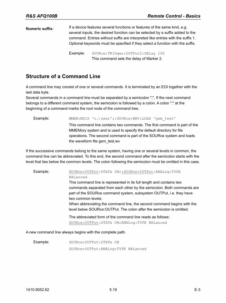
R&S AFQ100B Remote Control - Basics
1410.9052.62 5.19 E-3
Numeric suffix: If a device features several functions or features of the same kind, e.g. several inputs, the desired function can be selected by a suffix added to the command. Entries without suffix are interpreted like entries with the suffix 1. Optional keywords must be specified if they select a function with the suffix.
Example: SOURce:TRIGger:OUTPut2:DELay 100 This command sets the delay of Marker 2.
Structure of a Command Line
A command line may consist of one or several commands. It is terminated by an EOI together with the last data byte. Several commands in a command line must be separated by a semicolon ";". If the next command belongs to a different command system, the semicolon is followed by a colon. A colon ":" at the beginning of a command marks the root node of the command tree.
Example: MMEM:MSIS 'c.\user';:SOURce:WAV:LOAD 'gsm_test'
This command line contains two commands. The first command is part of the MMEMory system and is used to specify the default directory for file operations. The second command is part of the SOURce system and loads the waveform file gsm_test.wv
If the successive commands belong to the same system, having one or several levels in common, the command line can be abbreviated. To this end, the second command after the semicolon starts with the level that lies below the common levels. The colon following the semicolon must be omitted in this case.
Example: SOURce:OUTPut:STATe ON;:SOURce:OUTPut:ANALog:TYPE BALanced
This command line is represented in its full length and contains two commands separated from each other by the semicolon. Both commands are part of the SOURce command system, subsystem OUTPut, i.e. they have two common levels. When abbreviating the command line, the second command begins with the level below SOURce:OUTPut. The colon after the semicolon is omitted.
The abbreviated form of the command line reads as follows: SOURce:OUTPut:STATe ON;ANALog:TYPE BALanced
A new command line always begins with the complete path.
Example: SOURce:OUTPut:STATe ON
SOURce:OUTPut:ANALog:TYPE BALanced

Remote Control - Basics R&S AFQ100B
1410.9052.62 5.20 E-3
Responses to Queries
A query is defined for each setting command unless explicitly specified otherwise. It is formed by adding a question mark to the associated setting command. According to SCPI, the responses to queries are partly subject to stricter rules than in standard IEEE 488.2. 1. The requested parameter is transmitted without header.
Example: DIAGnostic:POINt:CATalog?
Answer: DIAG_GND,DIAG_P5V,DIAG_P3V3,... 2. Maximum values, minimum values and all further quantities, which are requested via a special text
parameter are returned as numerical values. Example: SOURce:TRIGger:OUTPut3:DELay:MAXimum?
Answer: 4000 3. Boolean values are returned as 0 (for OFF) and 1 (for ON).
Example: OUTPut:STATe?
Answer (for ON): 1 4. Text (character data) is returned in a short form.
Example: SOURce:OUTPut:ANALog:TYPE?
Answer (for BALanced): BAL
Parameters
Most commands require a parameter to be specified. The parameters must be separated from the header by a 'white space'. Permissible parameters are numerical values, Boolean parameters, text, character strings and block data. The type of parameter required for the respective command and the permissible range of values are specified in the command description.
Numerical values Numerical values can be entered in any form, i.e. with sign, decimal point and exponent. Values exceeding the resolution of the instrument are rounded up or down. The mantissa may comprise up to 255 characters, the values must be in the value range -9.9E37 to 9.9E37. The exponent is introduced by an 'E' or 'e'. Entry of the exponent alone is not allowed.
Units In the case of physical quantities, the unit can be entered. Permissible unit prefixes are G (giga), MA (mega), MOHM and MHZ are also permissible), K (kilo), M (milli), U (micro) and N (nano). If the unit is missing, the basic unit is used.
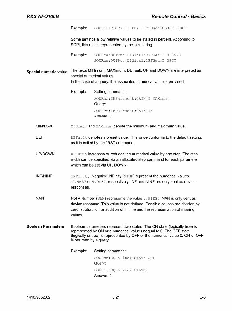
R&S AFQ100B Remote Control - Basics
1410.9052.62 5.21 E-3
Example: SOURce:CLOCk 15 kHz = SOURce:CLOCk 15000
Some settings allow relative values to be stated in percent. According to SCPI, this unit is represented by the PCT string.
Example: SOURce:OUTPut:DIGital:OFFSet:I 0.05FS SOURce:OUTPut:DIGital:OFFSet:I 5PCT
Special numeric value The texts MINimum, MAXimum, DEFault, UP and DOWN are interpreted as special numerical values. In the case of a query, the associated numerical value is provided.
Example: Setting command:
SOURce:IMPairment:GAIN:I MAXimum Query:
SOURce:IMPairment:GAIN:I? Answer: 0
MIN/MAX MINimum and MAXimum denote the minimum and maximum value. DEF DEFault denotes a preset value. This value conforms to the default setting,
as it is called by the *RST command. UP/DOWN UP, DOWN increases or reduces the numerical value by one step. The step
width can be specified via an allocated step command for each parameter which can be set via UP, DOWN.
INF/NINF INFinity, Negative INFinity (NINF) represent the numerical values
-9.9E37 or 9.9E37, respectively. INF and NINF are only sent as device responses.
NAN Not A Number (NAN) represents the value 9.91E37. NAN is only sent as
device response. This value is not defined. Possible causes are division by zero, subtraction or addition of infinite and the representation of missing values.
Boolean Parameters Boolean parameters represent two states. The ON state (logically true) is represented by ON or a numerical value unequal to 0. The OFF state (logically untrue) is represented by OFF or the numerical value 0. ON or OFF is returned by a query.
Example: Setting command:
SOURce:EQUalizer:STATe OFF Query:
SOURce:EQUalizer:STATe? Answer: 0

Remote Control - Basics R&S AFQ100B
1410.9052.62 5.22 E-3
Text Text parameters observe the syntax rules for key words, i.e. they can be entered using a short or long form. Like any parameter, they have to be separated from the header by a white space. In the case of a query, the short form of the text is provided.
Example: Setting command: SOURce:TRIGger:SOURce MANual
Strings Strings must always be entered within quotation marks (' or ").
Example: DIAGnostic:MEASure:POINt? "DIAG_P5V"
Block data Block data are a transmission format which is suitable for the transmission of large amounts of data. A command using a block data parameter with definite length has the following structure:
Example: MMEMory:DATA test_file.wv,#45168xxxxxxxx Test_file.wv denotes the name of the file to which the data are written. The comma is followed by the binary data block. The hash symbol # introduces the data block. The next number indicates how many of the following digits describe the length of the data block. In the example the 4 following digits indicate the length to be 5168 bytes. The data bytes follow. During the transmission of these data bytes all End or other control signs are ignored until all bytes are transmitted.
The format of the binary files within the block depends on the IEC/IEEE-bus command. Use the IEEE-754 format for double precision floating point numbers. Each number is represented by 8 bytes.
Example: a# = 125.345678E6
b# = 127.876543E6 CALL IBWRT(modulator%, "SOURCE:CORRECTION:CSET:DATA:FREQ #216" + MKD$(a#) + MKD$(b#)) − #' in the command string introduces the binary block, − '2' indicates that 2 digits specifying the length will follow next, − 16' is the length of the binary block (in bytes), here: 2 double
precision floating point number with 8 bytes each. − The actual binary data follow now. As the function IBWRT
requires a text string, MKD$ is used for the type conversion. The following ASCII format has the same effect: CALL IBWRT(modulator%, "SOURCE:CORRECTION:CSET:DATA:FREQ 125.345678E6, 127.876543E6")
R&S AFQ100B Remote Control - Basics
1410.9052.62 5.23 E-3
Overview of Syntax Elements
The following survey offers an overview of the syntax elements. : The colon separates the key words of a command. In a command line the separating
semicolon marks the uppermost command level. ; The semicolon separates two commands of a command line. , The comma separates several parameters of a command. ? The question mark forms a query. * The asterisk marks a common command. " Quotation marks introduce a string and terminate it. # The hash symbol # introduces binary, octal, hexadecimal and block data.
Binary: #B10110 Octal: #O7612 Hexa: #HF3A7 Block: #21312
A white space (ASCII-Code 0 to 9, 11 to 32 decimal, e.g. blank) separates header and parameter.
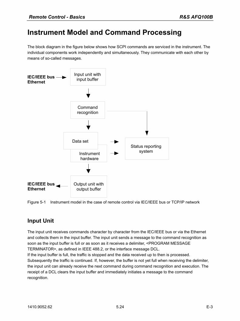
Remote Control - Basics R&S AFQ100B
1410.9052.62 5.24 E-3
Instrument Model and Command Processing
The block diagram in the figure below shows how SCPI commands are serviced in the instrument. The individual components work independently and simultaneously. They communicate with each other by means of so-called messages.
IEC/IEEE busEthernet
Input unit withinput buffer
Commandrecognition
Data set
Instrument hardware
Output unit withoutput buffer
Status reportingsystem
IEC/IEEE busEthernet
Figure 5-1 Instrument model in the case of remote control via IEC/IEEE bus or TCP/IP network
Input Unit
The input unit receives commands character by character from the IEC/IEEE bus or via the Ethernet and collects them in the input buffer. The input unit sends a message to the command recognition as soon as the input buffer is full or as soon as it receives a delimiter, <PROGRAM MESSAGE TERMINATOR>, as defined in IEEE 488.2, or the interface message DCL. If the input buffer is full, the traffic is stopped and the data received up to then is processed. Subsequently the traffic is continued. If, however, the buffer is not yet full when receiving the delimiter, the input unit can already receive the next command during command recognition and execution. The receipt of a DCL clears the input buffer and immediately initiates a message to the command recognition.
R&S AFQ100B Remote Control - Basics
1410.9052.62 5.25 E-3
Command Recognition
The command recognition analyses the data received from the input unit. It proceeds in the order in which it receives the data. Only a DCL is serviced with priority, a GET (Group Execute Trigger), e.g., is only executed after the commands received before. Each recognized command is immediately transmitted to the data set but not executed immediately. The command recognition detects syntax errors in the commands and transfers them to the status reporting system. The rest of a command line after a syntax error is analyzed further if possible and serviced. After the syntax test, the value range of the parameter is checked, if required. If the command recognition detects a delimiter or a DCL, it also requests the data set to perform the necessary instrument hardware settings. Subsequently it is immediately prepared to process further commands. This means that new commands can already be serviced while the hardware is still being set ("overlapping execution").
Data Base and Instrument Hardware
The expression "instrument hardware" denotes the part of the instrument fulfilling the actual instrument function - signal generation etc. The controller is not included. The term "database" denotes a database that manages all the parameters and associated settings required for setting the instrument hardware. Setting commands lead to an alteration in the data set. The data set management enters the new values (e.g. frequency) into the data set, however, only passes them on to the hardware when requested by the command recognition. As this is only ever effected at the end of a command line, the order of the setting commands in the command line is not relevant. The data are only checked for their compatibility among each other and with the instrument hardware immediately before they are transmitted to the instrument hardware. If the detection is made that execution is not possible, an "execution error" is signaled to the status reporting system. All alterations of the data set are canceled, the instrument hardware is not reset. Due to the delayed checking and hardware setting, however, impermissible instrument states can be set for a short period of time within one command line without this leading to an error message. At the end of the command line, however, a permissible instrument state must have been reached again.
Status Reporting System
The status reporting system collects information on the instrument state and makes it available to the output unit on request. The exact structure and function are described in section �Status Reporting System�, on page 5.27.
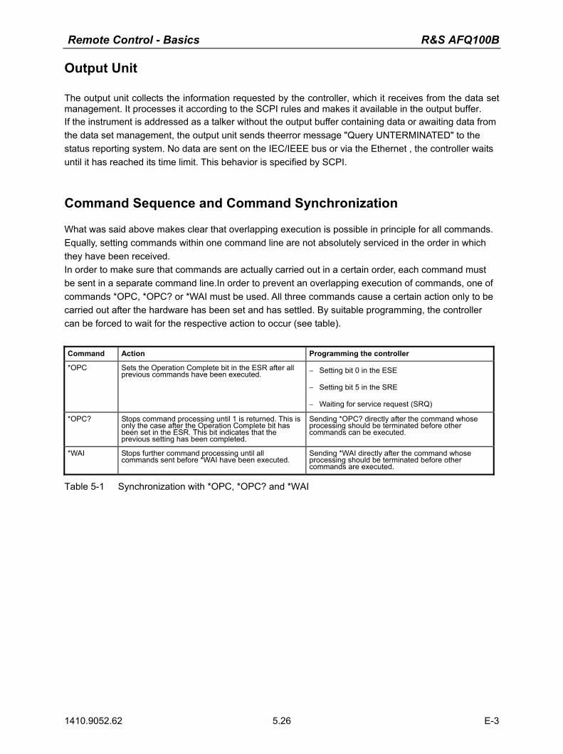
Remote Control - Basics R&S AFQ100B
1410.9052.62 5.26 E-3
Output Unit
The output unit collects the information requested by the controller, which it receives from the data set management. It processes it according to the SCPI rules and makes it available in the output buffer. If the instrument is addressed as a talker without the output buffer containing data or awaiting data from the data set management, the output unit sends theerror message "Query UNTERMINATED" to the status reporting system. No data are sent on the IEC/IEEE bus or via the Ethernet , the controller waits until it has reached its time limit. This behavior is specified by SCPI.
Command Sequence and Command Synchronization
What was said above makes clear that overlapping execution is possible in principle for all commands. Equally, setting commands within one command line are not absolutely serviced in the order in which they have been received. In order to make sure that commands are actually carried out in a certain order, each command must be sent in a separate command line.In order to prevent an overlapping execution of commands, one of commands *OPC, *OPC? or *WAI must be used. All three commands cause a certain action only to be carried out after the hardware has been set and has settled. By suitable programming, the controller can be forced to wait for the respective action to occur (see table).
Command Action Programming the controller
*OPC Sets the Operation Complete bit in the ESR after all previous commands have been executed. − Setting bit 0 in the ESE
− Setting bit 5 in the SRE
− Waiting for service request (SRQ)
*OPC? Stops command processing until 1 is returned. This is only the case after the Operation Complete bit has been set in the ESR. This bit indicates that the previous setting has been completed.
Sending *OPC? directly after the command whose processing should be terminated before other commands can be executed.
*WAI Stops further command processing until all commands sent before *WAI have been executed.
Sending *WAI directly after the command whose processing should be terminated before other commands are executed.
Table 5-1 Synchronization with *OPC, *OPC? and *WAI
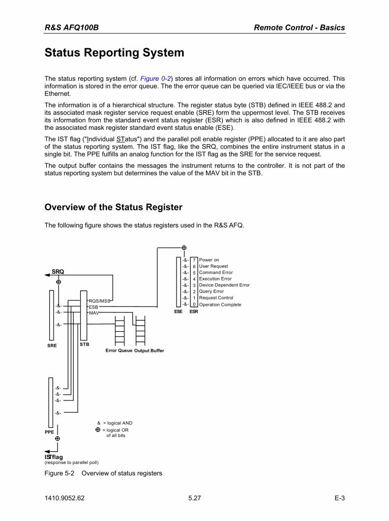
R&S AFQ100B Remote Control - Basics
1410.9052.62 5.27 E-3
Status Reporting System
The status reporting system (cf. Figure 0-2) stores all information on errors which have occurred. This information is stored in the error queue. The the error queue can be queried via IEC/IEEE bus or via the Ethernet.
The information is of a hierarchical structure. The register status byte (STB) defined in IEEE 488.2 and its associated mask register service request enable (SRE) form the uppermost level. The STB receives its information from the standard event status register (ESR) which is also defined in IEEE 488.2 with the associated mask register standard event status enable (ESE).
The IST flag ("Individual STatus") and the parallel poll enable register (PPE) allocated to it are also part of the status reporting system. The IST flag, like the SRQ, combines the entire instrument status in a single bit. The PPE fulfills an analog function for the IST flag as the SRE for the service request.
The output buffer contains the messages the instrument returns to the controller. It is not part of the status reporting system but determines the value of the MAV bit in the STB.
Overview of the Status Register
The following figure shows the status registers used in the R&S AFQ.
SRE STB
PPE
IST flag(response to parallel poll)
& = logical AND= logical OR of all bits
ESE ESR
Error Queue Output Buffer
SRQ
RQS/MSSESBMAV
Power onUser RequestCommand ErrorExecution ErrorDevice Dependent ErrorQuery ErrorRequest ControlOperation Complete
-&--&--&-
-&-
-&--&-
-&-
-&--&--&--&--&--&--&--&-
76543210
Figure 5-2 Overview of status registers

Remote Control - Basics R&S AFQ100B
1410.9052.62 5.28 E-3
Status Byte (STB) and Service Request Enable Register (SRE)
The STB is already defined in IEEE 488.2. It provides a rough overview of the instrument status by collecting the pieces of information of the lower registers. It assummes the highest level within the SCPI hierarchy. A special feature is that bit 6 acts as the sum bit of the remaining bits of the status byte. The STATUS BYTE is read out using the command "*STB?" or a serial poll. The STB is linked to the SRE. The latter corresponds to the ENABle part of the SCPI registers in its function. Each bit of the STB is assigned a bit in the SRE. Bit 6 of the SRE is ignored. If a bit is set in the SRE and the associated bit in the STB changes from 0 to 1, a Service Request (SRQ) is generated on the IEC/IEEE bus or via the Ethernet, which triggers an interrupt in the controller if this is appropriately configured and can be further processed there. The SRE can be set using command "*SRE" and read using "*SRE?". Bit no. Meaning
0...1 Not used 2 Error Queue not empty
The bit is set when an entry is made in the error queue. If this bit is enabled by the SRE, each entry of the error queue generates a Service Request. Thus an error can be recognized and specified in greater detail by polling the error queue. The poll provides an informative error message. This procedure is to be recommended since it considerably reduces the problems involved with Remote control.
3 Not used 4 MAV bit (Message available)
The bit is set if a message is available in the output buffer which can be read. This bit can be used to enable data to be automatically read from the instrument to the controller.
5 ESB bit
Sum bit of the event status register. It is set if one of the bits in the event status register is set and enabled in the event status enable register. Setting of this bit indicates a serious error which can be specified in greater detail by polling the event status register.
6 MSS bit (Master-Status-Summary-Bit)
The bit is set if the instrument triggers a service request. This is the case if one of the other bits of this register is set together with its mask bit in the service request enable register SRE.
7 Not used Table 5-2 Meaning of the bits used in the status byte
IST-Flag and Parallel Poll Enable Register (PPE)
By analogy with the SRQ, the IST flag combines the entire status information in a single bit. It can be queried by means of a parallel poll (cf. section "Parallel Poll" on page 5.31) or using the command "*IST?". The parallel poll enable register (PPE) determines which bits of the STB contribute to the IST flag. The bits of the STB are ANDed with the corresponding bits of the PPE, with bit 6 being used as well in contrast to the SRE. The IST flag results from the ORing of all results. The PPE can be set using commands "*PRE" and read using command "*PRE?".

R&S AFQ100B Remote Control - Basics
1410.9052.62 5.29 E-3
Event Status Register (ESR) and Event Status Enable Register (ESE)
The ESR is defined in IEEE 488.2. The event status register can be read out using command "*ESR?". The ESE is the associated ENABle part. It can be set using the command "*ESE" and read using the command "*ESE?".
Bit No. Meaning
0 Operation Complete
This bit is set on receipt of the command *OPC exactly when all previous commands have been executed.
1 not used
2 Query Error
This bit is set if either the controller wants to read data from the instrument without having sent a query, or if it does not fetch requested data and sends new instructions to the instrument instead. The cause is often a query which is faulty and hence cannot be executed.
3 Device-dependent Error
This bit is set if a device-dependent error occurs. An error message with a number between -300 and -399 or a positive error number, which denotes the error in greater detail, is entered into the error queue.
4 Execution Error
This bit is set if a received command is syntactically correct but cannot be performed for other reasons. An error message with a number between -200 and -300, which denotes the error in greater detail, is entered into the error queue.
5 Command Error
This bit is set if a command which is undefined or syntactically incorrect is received. An error message with a number between -100 and -200, which denotes the error in greater detail, is entered into the error queue.
6 User Request
This bit is set when the instrument is switched over to manual control.
7 Power On (supply voltage on)
This bit is set on switching on the instrument.
Table 5-3 Meaning of the bits used in the event status register
Remote Control - Basics R&S AFQ100B
1410.9052.62 5.30 E-3
Application of the Status Reporting System
In order to effectively use the status reporting system, the information contained there must be transmitted to the controller and further processed. There are several methods, which are outlined in the following.
Service Request
Under certain circumstances, the instrument can send a service request (SRQ) to the controller. Usually this service request initiates an interrupt at the controller, to which the control program can react appropriately. As evident from section "Overview of the Status Register" on page 5.27, an SRQ is always initiated if one or several of bits 2, 4, or 5 of the status byte are set and enabled in the SRE. Each of these bits combines the information of a further register, the error queue or the output buffer. In order to use the possibilities of the service request effectively, all bits should be set to "1" in the enable registers SRE and ESE.
Example:
Use command "*OPC" to generate an SRQ
CALL IBWRT(modulator%, "*ESE 1") set bit 0 of ESE (Operation Complete) CALL IBWRT(modulator%, "*SRE 32") set bit 5 of SRE (ESB) After its settings have been completed, the instrument generates an SRQ.
The SRQ is the only possibility for the instrument to become active on its own. Each controller program should set the instrument such that a service request is initiated in the case of malfunction. The program should react appropriately to the service request.
Serial Poll
In a serial poll, just as upon the command "*STB", the status byte of an instrument is queried. However, the query is made via interface messages and is thus clearly faster. The serial-poll method has already been defined in IEEE 488.1 and used to be the only standard possibility for different instruments to poll the status byte. The method also works for instruments which do not adhere to SCPI or IEEE 488.2. The Visual Basic command for executing a serial poll is "IBRSP()". The serial poll is mainly used to obtain a fast overview of the state of several instruments connected to the IEC/IEEE bus or via the Ethernet.
R&S AFQ100B Remote Control - Basics
1410.9052.62 5.31 E-3
Parallel Poll
In a parallel poll, the controller uses a single command to request up to eight instruments to transmit one bit of information each on the data lines, i.e., to set the data line allocated to each instrument to a logical "0" or "1". In addition to the SRE register, which determines the conditions under which an SRQ is generated, there is a parallel poll enable register (PPE). This register is ANDed with the STB bit by bit, considering bit 6 as well. The results are ORed, the result is possibly inverted and then sent as a response to the parallel poll of the controller. The result can also be queried without parallel poll by means of the command "*IST?". The instrument first has to be set for the parallel poll using the Visual Basic command "IBPPC()". This command allocates a data line to the instrument and determines whether the response is to be inverted. The parallel poll itself is executed using "IBRPP()". The parallel poll method is mainly used to find out quickly which one of the instruments connected to the IEC/IEEE bus has sent a service request. To this effect, SRE and PPE must be set to the same value.
Query by Means of Commands
Each part of any status register can be read by means of queries. The individual commands are listed in the description of the STATus Subsystem. The returned value is always a number that represents the bit pattern of the register queried. This number is evaluated by the controller program. Queries are usually used after an SRQ in order to obtain more detailed information on the cause of the SRQ.
Error Queue Query
Each error state in the instrument leads to an entry in the error queue. The entries of the error queue are detailed plain-text error messages that can be looked at in the ERROR menu via manual control or queried via the IEC/IEEE bus or via the Ethernet using command "SYSTem:ERRor?". Each call of "SYSTem:ERRor?" provides one entry from the error queue. If no error messages are stored there any more, the instrument responds with 0, "No error". The error queue should be queried after every SRQ in the controller program as the entries describe the cause of an error more precisely than the status registers. Especially in the test phase of a controller program the error queue should be queried regularly since faulty commands from the controller to the instrument are recorded there as well.

Remote Control - Basics R&S AFQ100B
1410.9052.62 5.32 E-3
Reset Values of the Status Reporting Systems
Commands *RST, *DCL and SYSTem:PRESet and switching on the supply voltage also affect the status reporting system. None of the commands, except for *RST and SYSTem:PRESet influences the functional instrument settings. In particular, DCL does not change the instrument settings. Event Switching on
supply voltage
DCL,SDC
Power-On-Status-Clear
(Device Clear, Selected Device Clear)
*RST or SYSTem:PRESet
STATus:PRESet *CLS
Effect 0 1
Clear STB,ESR � yes � � � yes
Clear SRE,ESE � yes � � � �
Clear PPE � yes � � � �
Clear error-queue yes yes � � � yes
Clear output buffer yes yes yes 1) 1) 1)
Clear command processing and input buffer
yes yes yes � � �
Table 5-4 Resetting the Status Reporting System
1) Every command being the first in a command line, i.e. immediately following a <PROGRAM MESSAGE TERMINATOR> clears the output buffer
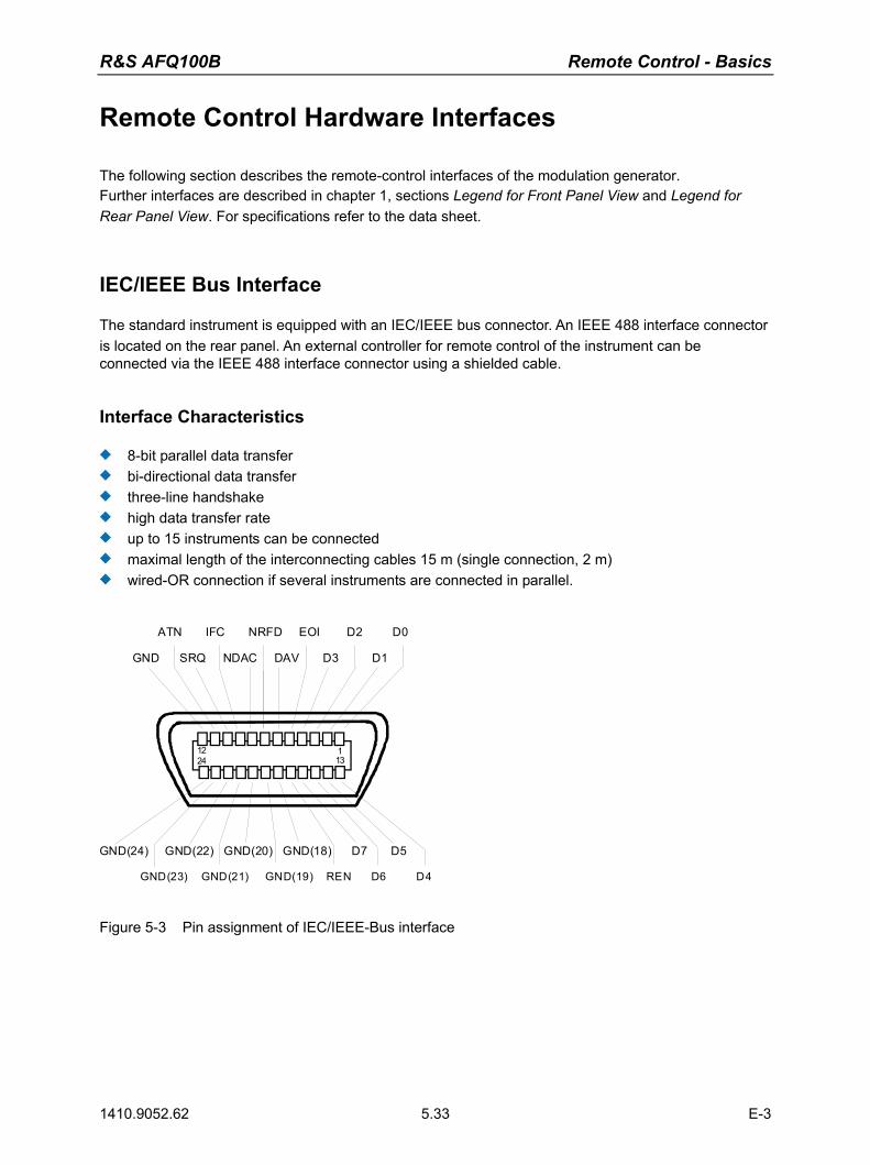
R&S AFQ100B Remote Control - Basics
1410.9052.62 5.33 E-3
Remote Control Hardware Interfaces
The following section describes the remote-control interfaces of the modulation generator. Further interfaces are described in chapter 1, sections Legend for Front Panel View and Legend for Rear Panel View. For specifications refer to the data sheet.
IEC/IEEE Bus Interface
The standard instrument is equipped with an IEC/IEEE bus connector. An IEEE 488 interface connector is located on the rear panel. An external controller for remote control of the instrument can be connected via the IEEE 488 interface connector using a shielded cable.
Interface Characteristics
8-bit parallel data transfer bi-directional data transfer three-line handshake high data transfer rate up to 15 instruments can be connected maximal length of the interconnecting cables 15 m (single connection, 2 m) wired-OR connection if several instruments are connected in parallel.
12 11324
GND SRQ NDAC DAV D3 D1
GND(24) GND(22) GND(20) GND(18) D7 D5
GND(23) GND(21) GND(19) REN D6 D4
ATN IFC NRFD EOI D2 D0
Figure 5-3 Pin assignment of IEC/IEEE-Bus interface
Remote Control - Basics R&S AFQ100B
1410.9052.62 5.34 E-3
Bus Lines
Data bus with 8 lines D0 to D7
The transmission is bit-parallel and byte-serial in the ASCII/ISO code. D0 is the least significant bit, D7 the most significant bit.
Control bus with 5 lines
IFC (Interface Clear)
active LOW resets the interfaces of the instruments connected to the default setting.
ATN (Attention)
active LOW signals the transmission of interface messages. inactive HIGH signals the transmission of device messages.
SRQ (Service Request)
active LOW enables the connected device to send a service request to the controller.
REN (Remote Enable)
active LOW permits switchover to remote control.
EOI (End or Identify)
has two functions in connection with ATN: ATN = HIGH active LOW marks the end of data transmission. ATN = LOW active LOW triggers a parallel poll.
Handshake bus with three lines
DAV (Data Valid)
active LOW signals a valid data byte on the data bus.
NRFD (Not Ready For Data)
active LOW signals that one of the connected devices is not ready for data transfer.
NDAC (Not Data Accepted)
active LOW signals that the instrument connected is accepting the data on the data bus.
R&S AFQ100B Remote Control - Basics
1410.9052.62 5.35 E-3
IEC/IEEE-Bus Interface Functions
Instruments which can be remote controlled via the IEC/IEEE bus can be equipped with different interface functions. The following table lists the interface functions appropriate for the instrument.
Control character Interface function
SH1 Handshake source function (source handshake), full capability
AH1 Handshake sink function (acceptor handshake), full capability
L4 Listener function, full capability, unaddress if MTA.
T6 Talker function, full capability, ability to respond to serial poll, unaddress if MLA
SR1 Service request function (Service Request), full capability
PP1 Parallel poll function, full capability
RL1 Remote/Local switch over function, full capability
DC1 Reset function (Device Clear), full capability
DT1 Trigger function (Device Trigger), full capability
C0 No controller function
Table 5-5 IEC/IEEE Bus Interface functions
IEC/IEEE Bus Messages
Interface messages are transferred on the data lines of the IEC/IEEE bus when the "ATN" control line is active (LOW). They are used for communication between controller and instruments and can only be sent by the controller which currently has control of the IEC/IEEE bus.
Universal Commands The universal commands are encoded 10 - 1F hex. They affect all instruments connected to the bus without addressing. Command Visual Basic command Effect on the instrument
DCL
(Device Clear)
IBCMD (controller%, CHR$(20)) Aborts the processing of the commands just received and sets the command processing software to a defined initial state. Does not change the instrument settings..
IFC
(Interface Clear)
IBSIC (controller%) Resets the interfaces to the default setting.
LLO
(Local Lockout)
IBCMD (controller%, CHR$(17)) Locks switchover from remote control to manual control by means of the front panel keys
SPE
(Serial Poll Enable)
IBCMD (controller%, CHR$(24)) Ready for serial poll.
SPD
(Serial Poll Disable)
IBCMD (controller%, CHR$(25)) End of serial poll.
PPU
(Parallel Poll Unconfigure)
IBCMD (controller%, CHR$(21)) End of the parallel-poll state.
Table 5-6 Universal Commands
Remote Control - Basics R&S AFQ100B
1410.9052.62 5.36 E-3
Addressed Commands The addressed commands are encoded 00 - 0F hex. They are only effective for instruments addressed as listeners. Command VISUAL BASIC Command Effect on the instrument
SDC
(Selected Device Clear)
IBCLR (device%) Aborts the processing of the commands just received and sets the command processing software to a defined initial state. Does not change the instrument setting.
GET
(Group Execute Trigger)
IBTRG (device%) Triggers a previously active device function (eg a sweep). The effect of the command is the same as with that of a pulse at the external trigger signal input.
GTL
(Go to Local)
IBLOC (device%) Transition to the "Local" state (manual control).
PPC
(Parallel Poll Configure)
IBPPC (device%, data%) Configures instrument for parallel poll. Additionally, the VISUAL BASIC command executes PPE/PPD.
Table 5-7 Addressed Commands
LAN Connector
The unit is equipped with an LAN interface as standard. The LAN connector is at the rear of the instrument. Provided the appropriate rights have been assigned by the network administrator, files can be transmitted via the network, and network resources, e.g. a network folders, can be used. The instrument can also be remote-controlled and manually operated in the network. It is connected by means of a commercial RJ45 cable. The network card functions with 10/100/1000Mbps Ethernet IEEE 802.3u. The TCP/IP network protocol and the associated network services are preconfigured. TCP/IP ensures connection-oriented communication, where the order of the exchanged messages is adhered to and interrupted links are identified. With this protocol, messages cannot be lost. Connection of the R&S AFQ is described in chapter 1, section "Connecting the R&S AFQ to a Network (LAN)", remote control via Ethernet in section "Remote Control via LAN Interface" on page 5.8. The architecture of a LAN remote-control connection is described in detail in the following. Remote control of an instrument via a network is based on standardized protocols which follow the OSI reference model (see Fig. below).
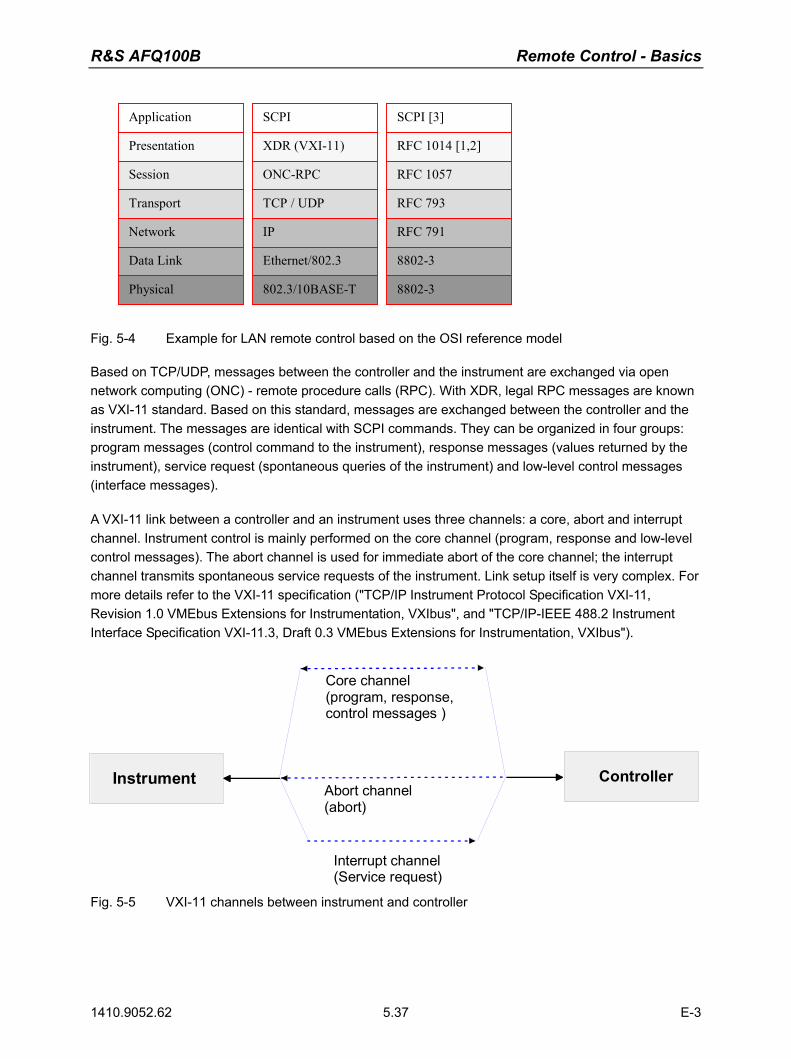
R&S AFQ100B Remote Control - Basics
1410.9052.62 5.37 E-3
SCPI
XDR (VXI-11)
ONC-RPC
TCP / UDP
IP
Ethernet/802.3
802.3/10BASE-T
Application
Presentation
Session
Transport
Network
Data Link
Physical
SCPI [3]
RFC 1014 [1,2]
RFC 1057
RFC 793
RFC 791
8802-3
8802-3
Fig. 5-4 Example for LAN remote control based on the OSI reference model Based on TCP/UDP, messages between the controller and the instrument are exchanged via open network computing (ONC) - remote procedure calls (RPC). With XDR, legal RPC messages are known as VXI-11 standard. Based on this standard, messages are exchanged between the controller and the instrument. The messages are identical with SCPI commands. They can be organized in four groups: program messages (control command to the instrument), response messages (values returned by the instrument), service request (spontaneous queries of the instrument) and low-level control messages (interface messages). A VXI-11 link between a controller and an instrument uses three channels: a core, abort and interrupt channel. Instrument control is mainly performed on the core channel (program, response and low-level control messages). The abort channel is used for immediate abort of the core channel; the interrupt channel transmits spontaneous service requests of the instrument. Link setup itself is very complex. For more details refer to the VXI-11 specification ("TCP/IP Instrument Protocol Specification VXI-11, Revision 1.0 VMEbus Extensions for Instrumentation, VXIbus", and "TCP/IP-IEEE 488.2 Instrument Interface Specification VXI-11.3, Draft 0.3 VMEbus Extensions for Instrumentation, VXIbus").
Instrument Controller
Interrupt channel(Service request)
Abort channel(abort)
Core channel(program, response, control messages )
Fig. 5-5 VXI-11 channels between instrument and controller

Remote Control - Basics R&S AFQ100B
1410.9052.62 5.38 E-3
The number of controllers that can address an instrument is practically unlimited in the network. In the instrument, the individual controllers are clearly distinguished. This distinction continues up to the application level in the controller, i.e. two applications on a PC are identified by the instrument as two different controllers.
Instrument Controller
Controller
Controller
Fig. 5-6 Remote control via LAN from several controllers The controllers can lock and unlock the instrument for exclusive access. This regulates access to the instrument of several controllers. In the 'Measurement & Automation Control' program, this setting is made on the Template tab.

R&S AFQ100B Remote Control - Basics
1410.9052.62 5.39 E-3
VXI-11 Interface Messages
On the Ethernet link, the interface messages are called low-level control messages. These messages can be used to emulate interface messages of the IEC/IEEE bus. Command Effect on the instrument
&ABO (Abort) Aborts the processing of the commands just received.
&DCL (Device Clear) Aborts the processing of the commands just received and sets the command processing software to a defined initial state. Does not change the instrument setting.
>L (Go to Local) Transition to the "Local" state (manual control)
>R (Go to Remote) Transition to the "Remote" state (remote control)
&GET (Group Execute Trigger) Triggers a previously active device function (eg a sweep). The effect of the command is the same as with that of a pulse at the external trigger signal input.
&LLO (Local Lockout) Disables switchover from remote control to manual control by means of the front panel keys
&POL (Serial Poll) Starts a serial poll
&NREN (Not Remote Enable) Enables switchover from remote control to manual control by means of the front panel keys
Table 5-8 VXI-11 Interface Messages


R&S AFQ100B Index
1410.9052.62 1 E-1
Index
& >L .............................................................5.5 >R.............................................................5.5 &LLO..............................................................5.5
A Abort button .................................................3.19 Aborting a calculation ..................................3.19 AC supply � Fuse box ...................................1.8 AC supply - Power connector ........................1.8 AC supply - Power switch..............................1.8 analog outputs ...............................................1.5 Asterisk ........................................................5.23
B BERT inputs...................................................1.9 BERT inputs - Segment address..................1.9 BERT inputs - CLOCK...................................1.9 BERT inputs - DATA......................................1.9 BERT inputs � DATA ENABL........................1.9 BERT inputs - FHOP .....................................1.9 BERT inputs - RESTART ..............................1.9 BERT inputs - Segment hopping...................1.9 Block data ....................................................5.22 Boolean parameter ......................................5.21 BUSY LED.....................................................1.2 BUSY POWER ..............................................1.3
C Character data.............................................5.20 Check-box field............................................3.14 Clock input ...................................................1.11 Clock input - REF ........................................1.11 Clock output.................................................1.11 Clock output - REF ......................................1.11 Colon (separator).........................................5.23 Comma (separator) .....................................5.23 Command
addressed .................................................5.36 header .......................................................5.17 Line ...........................................................5.19 parameters ................................................5.20 query .........................................................5.20 question mark............................................5.20 sequence...................................................5.26 structure ....................................................5.17 suffix..........................................................5.19 synchronization .........................................5.26 universal....................................................5.35
Connection to external controller ................ 1.35 Controller, external...................................... 1.35 Cross-over RJ-45 cable .............................. 1.27
D DCL 5.24 Decimal point .............................................. 5.20 Delimiter ...................................................... 5.24 DHCP.......................................................... 1.27 Dialog area.................................................. 3.14 Dialog header.............................................. 3.13 digital outputs................................................ 1.5 Display .......................................................... 3.7 Double dagger (#) ....................................... 5.23
E Entry field .................................................... 3.14 EOI (command line) .................................... 5.19 ERROR LED ................................................. 1.2 Error messages............................................. 3.8 Error queue ................................................. 5.31 ESE (event status enable register) ............. 5.29 Ethernet................................................. 1.3,1.26 Ethernet - Remote control............................. 5.8 Event status enable register (ESE)............. 5.29 Exponent ..................................................... 5.20
F Firewall........................................................ 1.32 Firmware update ......................................... 1.12 Fuses .......................................................... 1.16
G GET (Group Execute Trigger)..................... 5.25 Graphical display ........................................ 3.15
H Header ........................................................ 5.17
I I/Q output ...................................................... 1.5 IEC/IEEE bus
Interface...................................................... 1.8 input - CLOCK............................................. 1.11 Input buffer .................................................. 5.24

Index R&S AFQ100B
1410.9052.62 E-1
Input clock - REF .........................................1.11 Input Trigger - NEXT ...................................1.11 Instrument settings ......................................3.26 Instrument settings - Exit .............................3.27 Instrument settings - New............................3.26 Instrument settings - Open ..........................3.26 Instrument settings - Save...........................3.27 Instrument settings � Save as... ..................3.27 Instrument settings reset .............................1.21 Interface - IEC/IEEE bus ...............................1.8 Interface function IEC/IEEE bus..................5.35 Internet Connection Firewall........................1.32 Interrupt .......................................................5.30 IP address....................................................1.28
K Key - PRESET.............................................1.21 Keyboard On-Screen.....................................3.3
L LAN 1.3,1.26,5.9,5.36 LAN - Interface ............................................5.36 LAN - Remote control ....................................5.8 LAN interface � Ethernet interface ................1.7 LAN LED........................................................1.3 Linux controller ............................................1.41 Local to remote switchover............................5.5 Lower-case (commands) .............................5.18 LXI LED .........................................................1.3
M Mantissa ......................................................5.20 Manual operation
return to...............................................5.7,5.13 Manually remote control ..............................1.35 MARKER 1-4 ...............................................1.10 MONITOR connector...................................1.10 Multi segment waveform - CLOCK input .......1.9 Multi segment waveform - DATA input..........1.9 Multi segment waveform - Input ....................1.9 Multi segment waveform - Input segment
address bit 0 (LSB) ................................1.9 Multi segment waveform - Input segment
address bit 1 ..........................................1.9 Multi segment waveform - Input segment
address bit 2 ..........................................1.9 Multi segment waveform - Input segment
address bit 3 (MSB) ...............................1.9 Multi segment waveform - Strobe input.........1.9
N Network card............................................... 1.26 Network drives ............................................ 1.33 Norton Antivirus 2005 ................................. 1.48 Numeric suffix ............................................. 5.18
O On/off switch ................................................. 1.3 Output - analog ............................................. 1.5 Output - CLOCK.......................................... 1.11 Output - digital............................................... 1.5 Output clock - REF...................................... 1.11 Output Trigger - TRIG................................. 1.11 Overlapping execution ................................ 5.25
P Parallel Poll ................................................. 5.31 Parameter (commands) .............................. 5.20 Point-to-point connection .................... 1.27,1.33 Power fuses ................................................ 1.16 PPE (Parallel poll enable register).............. 5.28 Preset.......................................................... 1.21
Q Query .................................................................
responses................................................. 5.20 Question...................................................... 5.23 Quotation marks.......................................... 5.23
R Rack installation.......................................... 1.12 READY LED.................................................. 1.2 Ready state................................................... 1.3 Remote control - Ethernet/LAN..................... 5.8 Remote control - GPIB.................................. 5.5 Remote control - manually .......................... 1.35 Remote control basics .................................. 5.1 Remote control switchover............................ 5.5 Remote Desktop Connection...................... 1.35 REMOTE LED............................................... 1.2 Remote to local switchover ........................... 5.5 Reset - Instrument settings ......................... 1.21 Reset status reporting system .................... 5.32 Restoring the previous value ...................... 3.19 RJ-45 cable................................................. 1.26
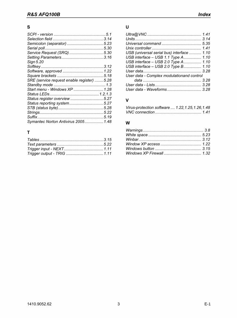
R&S AFQ100B Index
1410.9052.62 3 E-1
S SCPI - version ...............................................5.1 Selection field ..............................................3.14 Semicolon (separator) .................................5.23 Serial poll .....................................................5.30 Service Request (SRQ) ...............................5.30 Setting Parameters......................................3.16 Sign 5.20 Softkey.........................................................3.12 Software, approved .....................................1.22 Square brackets ..........................................5.18 SRE (service request enable register) ........5.28 Standby mode ...............................................1.3 Start menu - Windows XP ...........................1.28 Status LEDs.............................................1.2,1.3 Status register overview ..............................5.27 Status reporting system...............................5.27 STB (status byte).........................................5.28 Strings..........................................................5.22 Suffix............................................................5.19 Symantec Norton Antivirus 2005.................1.48
T Tables ..........................................................3.15 Text parameters ..........................................5.22 Trigger input - NEXT....................................1.11 Trigger output - TRIG ..................................1.11
U Ultra@VNC ................................................. 1.41 Units ............................................................ 3.14 Universal command .................................... 5.35 Unix controller ............................................. 1.41 USB (universal serial bus) interface ........... 1.10 USB interface � USB 1.1 Type A................ 1.10 USB interface � USB 2.0 Type A................ 1.10 USB interface � USB 2.0 Type B................ 1.10 User data..................................................... 3.28 User data - Complex modulationand control
data ..................................................... 3.28 User data - Lists.......................................... 3.28 User data - Waveforms ............................... 3.28
V Virus-protection software .... 1.22,1.25,1.26,1.48 VNC connection .......................................... 1.41
W Warnings....................................................... 3.8 White space ................................................ 5.23 Winbar......................................................... 3.12 Window XP access ..................................... 1.22 Windows button .......................................... 3.15 Windows XP Firewall .................................. 1.32