uu 3 - nasa · uu 3 low frequency high ... this paper presents a theory that explains low...
TRANSCRIPT

u u 3
Low Frequency High Amplitude Temperature Oscillations in Loop Heat Pipe Operation
Jentung Ku NASA Goddard Space Flight Center
Greenbelt, MD 20771
jentung.ku@,mfc.nasa.gov (301) 286-3130
Jose Rodriguez Jet Propulsion Laboratory
California Institute of Technology
ABSTRACT
This paper presents a theory that explains low frequency, high amplitude temperature oscillations in loop heat pipe (LHP) operation. Oscillations of the CC temperature with amplitudes on the order of tens of degrees Kelvin and periods on the order of hours have been observed in some LHPs during ambient testing. There are presently no satisfactory explanations for such a phenomenon in the literature. It is well-known that the operating temperature of an LHP with a single evaporator is governed by the compensation chamber (CC) temperature, which in turn is a function of the evaporator heat load, sink temperature, and ambient temperature. As the operating condition changes, the CC temperature will change during the transient but eventually reach a new steady temperature. Under certain conditions, however, the LHP never really reaches a true steady state, but instead displays an oscillatory behavior. The proposed new theory describes why low frequency, high amplitude oscillations may occur when the LHP has a low evaporator power, a low heat sink temperature (below ambient temperature), and a large thermal mass attached to the evaporator. When this condition prevails, there are some complex interactions between the CC, condenser, thermal mass and ambient. The temperature oscillation is a result of the large movement of the vapor front inside the condenser, which is caused by a change in the net evaporator power modulated by the large thermal mass through its interaction with the sink and CC. The theory agrees very well with previously published test data. Effects of various parameters on the amplitude and frequency of the temperature oscillation are also discussed.
INTRODUCTION
The operating temperature of a loop heat pipe (LHP) with a single evaporator is governed by the compensation chamber (CC) temperature, which in turn is a function of the evaporator heat load, condenser sink temperature, and ambient temperature. As the operating condition changes, the CC temperature will change during the transient but eventually reach a new steady temperature [l]. Under certain conditions, however, the LHP never really reaches a true steady state, but instead displays an oscillatory behavior. One obvious source of the temperature oscillation is an oscillation in the applied heat load or the sink temperature. However, even when the applied heat load and the sink temperature are held constant, temperature oscillations can still occur. Two types of temperature oscillation under such conditions have been published in the literature [2-61 as will be described below.
In the first type, the CC temperature displays high frequency (with periods on the order of seconds to minutes) and low amplitude (with temperature changes on the order of one degree Kelvin) oscillations. The oscillation is caused by the inability of the vapor front to find a stable position inside the condenser [2]. This type of temperature oscillation has been observed frequently in many LHPs in ground testing, and can in fact be purposely made to happen by adjusting the evaporator heat load and/or the sink temperature. Although the liquid line temperature may fluctuate wildly, it only leads to very small oscillations in the CC temperature, and is usually not much of a concern to the user. A comprehensive study of this type of temperature oscillation is given in Reference 7.
In the second type, the CC temperature displays a low frequency (with periods on the order of hours) and high amplitude (with temperature changes on the order of tens of degrees Kelvin) oscillations. There are three known conditions that can lead to this type of temperature oscillations in LHPs. The first condition
https://ntrs.nasa.gov/search.jsp?R=20030025361 2018-07-28T08:28:40+00:00Z

exists when the condenser sink temperature is oscillating while the net heat load to the evaporator is kept constant. This is what is to be expected in some space applications when the spacecraft is orbiting the Earth. Thermal vacuum testing of LHPs under simulated orbital sink conditions show that the CC temperature will oscillate in tandem with that of the sink temperature (with some phase shifts). The second condition exists in an LHP that has a single evaporator and two parallel condensers with individual flow regulators. The CC temperature oscillation is caused by the interaction between these two condensers when one of the sinks is warmer than the saturation temperature while the other is colder [3]. The flow regulator on the condenser with a warm sink will periodically dry out. This kind of temperature oscillation will diminish or disappear completely if the flow regulators for the individual condensers are placed next to each other and share the same heat sink so that the wicks will never dry out. The third condition leading to low frequency, high amplitude temperature oscillation has been reported when a large thermal mass is attached to the evaporator, a small heat load is applied to the evaporator section, and the sink temperature is below the ambient temperature [4,6]. This paper focuses specifically on the investigation of temperature oscillation under such a condition.
A theory that explains the source of the low frequency, high amplitude temperature oscillations in LHP operation will be presented. The thermavfluid processes involved will be described in detail based on the governing equations. Throughout this paper, test data reported in Reference 4 will be used. Thus, the test set-up and some results from Reference 4 will be briefly described first. A review of existing theory [5,6] will follow. A new theory will then be presented. Many of the test results in Reference 4 will be used to verify the new theory. Effects of various parameters on the amplitude and period of the temperature oscillation will also be discussed.
TESTING OF AN LHP
A test program was implemented at the Jet Propulsion Laboratory (JPL) to characterize the transient behavior of a propylene LHP with a large thermal mass attached to the evaporator [4]. The LHP was tested in a horizontal orientation with heat loads ranging from 15W to 75W and condenser sink temperatures from 243K to 293K. A schematic of the test loop with thermocouple locations is shown in Figure 1. Some key geometric parameters of the loop are presented in Table 1. The thermal mass consisted of a stack of copper blocks of the same width as the evaporator saddle. All tests were conducted with 2 1 kg of copper attached to the evaporator. An aluminum heater block, mounted on the top of the copper blocks, with two calrod heaters was used to provide heat to the evaporator. Similarly, an aluminum cooling block with a fluid heat exchanger was attached to the opposite side of the evaporator saddle to actively control its temperature when needed although none of the tests discussed in this paper had any active temperature control. The heat capacity of all six copper blocks including aluminum heater and cooling blocks is 9080 JK. This is equivalent to 10.2 kg of aluminum. A detailed description of the test loop is given in Reference 4.
Compensation r Chamber
1 5 h 6. Sol h Top 'Old 'ink OUl'
2
Tap View of 2O*Ambl*nl Evaporator
Embedded h*.ten. Q1
End View of .vww.lor
Condenser Plate
3.3
c
Figure 1. Schematic of the Test Loop with Thermocouple Locations (fig 6 . )
2

Table I. Key Geometric Parameter of Test Unit
Component Evaporator
Material I.D.
Length Primarv wick
Material Pore size Porosity
Permeability Compensation chamber
Material O.D.
Length Volume
Material I.D.
Wall thickness Vapor line length Liquid line length
Material I.D.
Wall thickness Length
Charge Purity
Material Dimension
Mass
Material Dimensions
Mass Large mass (each block)
Material Dimensions
Mass
Transport lines
Condenser
Propylene
Heating block
Cooling block
Description
6061 AL 2.421 cm 15.24 cm
Sintered nickel 1.2 pm 0.60 4x1 0.'' mz
316L SS 4.394 cm 8.025 cm 115 cm3
304L SS 0.452 cm 0.508 mm 1.00 m 1.074 m
6063 AL extrusion 0.399 cm 7.62 mm 3.81 m
80 grams 99+%
6061 AL 7.62 cm by 15.24 cm by 1.91 cm 0.5 kg
6061 AL 7.62 cm by 15.24 cm by 1.27 cm 0.5 kg
Copper 7.62 crn by 20.32 cm by 2.54 cm 3.5 kg
Figure 2 shows the loop temperatures with 25W to the evaporator at a sink temperature of 263K. The loop started when the CC temperature reached 3 10K. The CC temperature rapidly dropped to 280K, and then began to oscillate between 278K and 290K with a period of about 120 minutes. Such a large variation in the CC temperature may have a big impact on the loop operation and will be a concern to the LHP users. Some studies have been made in an attempt to gain a better understanding of this phenomenon as will be described in the next section.
(All Figures are in the attached powerpoint file) Figure 2. Loop Temperature at 25 W/263K -- Gfigure 14) (Tcc 4.7C to 16.5C)
REVIEW OF AN EXISTING MODEL
A mathematical model has been developed to simulate the low frequency, high amplitude temperature oscillation [5,6]. The main feature of the model can be described using a characteristic curve shown in Figure 3 where the temperature difference between the evaporator and the condenser is plotted against the

net heat load to the evaporator. The model states that at some temperature differences between the evaporator and the condenser, there can be two different heat loads to the evaporator, e.g. points 2 and 3 in Figure 3. Initially, the loop is represented by point 1 when it starts. The loop then operates at point 2 at which the sensible heat in the thermal mass is suddenly realized due to a CC temperature drop from point 1 to point 2, and the effective net heat load to the evaporatorjumps to point 3. This is followed by a gradual decrease of the net heat load from point 3 to point 4 and then to point 2. The cycle repeats afterwards. There are two main shortcomings in this model. First, the sudden jump of the evaporator heat load from point 2 to point 3 is physically impossible because all heat transfer processes take time, especially for heat transmission from the large thermal mass to the evaporator. Second, the parameter used on the ordinate in Figure 3 is somewhat ambiguous. The condenser temperature, Tcondenser, is either the average of all the thermocouple temperatures on the condenser, or the sink temperature. Although a plot based on the gross, average condenser temperature may give some insights in the LHP operation during steady state, it can not fully account for the detailed physical processes involved during transients. If the sink temperature is used, the plot will be similar to the plot where the CC temperature is used on the ordinate. In either case, as the thermal mass begins to release sensible heat, the CC temperature will begin to decrease. Thus, the net heat load to the evaporator will be increasing, not decreasing as proposed in Figure 3 (from point 3 to point 4). A new model proposed in the next section will show that a low frequency, high temperature oscillation is possible only in the region to the left of point 4, and is forbidden in the region on the right hand side.
Figure 3. Typical LHP Operating Curve Used in Existing Theory (Reference 5) flgure 10)
A NEW MODEL
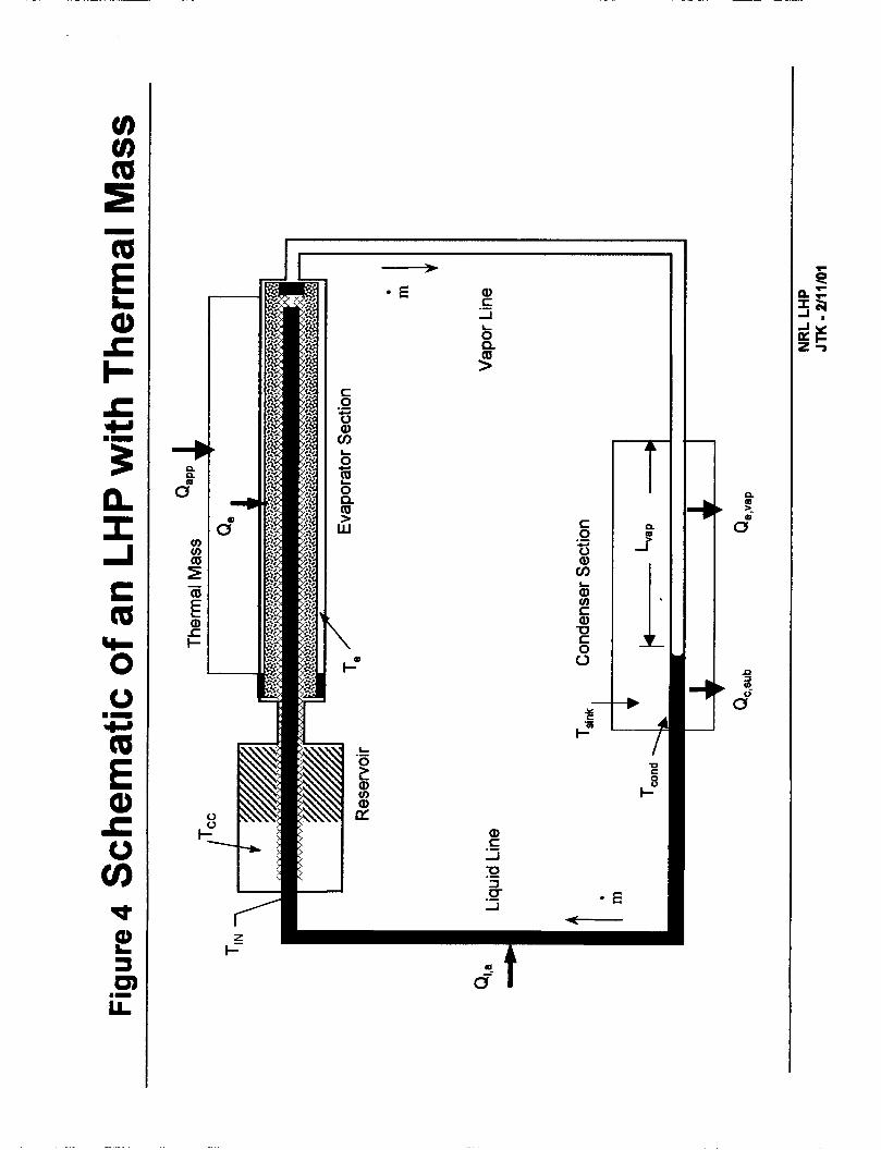
Figure 4. Schematic of an LHP
As shown schematically in Figure 4, a typical LHP consists of an evaporator, a CC, a condenser, and vapor and liquid transport lines. The evaporator is usually attached to an instrument (thermal mass) to be cooled. The heat transfer among LHP components and the environment is illustrated. The case without a thermal mass will be discussed first. The heat load that is applied to the evaporator can be divided into two parts. The first part is used to evaporate the liquid and establish a flow circulation around the loop. The second part is transmitted to the CC and is commonly referred to as the heat leak.
where Qe = net heat load applied to the evaporator, Qe,,, = heat leak from evaporator to CC, Qe,vap = heat load going to liquid evaporation, Te = evaporator temperature, T,, = CC temperature, m = mass flow rate, h = heat of vaporization of the working fluid, and G,,, = thermal conductance between evaporator and CC.
The vapor generated in the evaporator due to the heat load Qe,vap is condensed in the condenser over a certain length. Although in reality the vapor content continues to decrease as the vapor moves downstream of the condenser, for illustration purpose it is assumed that a sharp vapor front (liquidvapor interface) exists. Thus the distance from the inlet of the condenser to the vapor front, Lvap, can be expressed as:
Lvap = Qe,vap /[hXD (Tcc - Tsid] (4)
where h is the condensation heat transfer coefficient, D is the inner diameter of the condenser tube, and Tsik is the condenser sink temperature. Equation (4) further assumes that the vapor enters the condenser at the saturation temperature although it may be slightly superheated. The condensed liquid is further
4

subcooled in the remainder of the condenser section, and dissipates an amount of heat of Qc,sub before leaving the condenser at a temperature Tcand. As the liquid flows along the liquid line, it exchanges heat with its surroundings and enters the CC at a temperature Ti,. The temperature difference can be expressed as:
where Q I , ~ is the heat leak to the liquid from the surrounding and C is the liquid specific heat.
The saturation temperature of a well-insulated CC is determined by an energy balance between the heat leak and the subcooling of the returning liquid:
Furthermore, because the CC and the evaporator outer grooves both contain two-phase fluid, the Clausius- Clapeyron relation applies:
AP = h (T, -Tee)/ (T,, Av) (8)
where Av is the difference in the vapor and liquid specific volumes, and AP is equal to the total system pressure drop minus the pressure drop through the wick.
A schematic showing details of the vapor front inside the condenser is shown in Figure 5. For a given set of heat load, sink temperature and ambient temperature, the above governing equations uniquely define a vapor length in the condenser, Lvap, and a CC temperature T,,, assuming there is no temperature hysteresis. When the evaporator power changes, T,, and Lvap will also change. Thus, a characteristic curve can be obtained as shown in Figure 6 , where the CC temperature is plotted as a function of the net heat load to the evaporator at given sink and ambient temperatures. Detailed descriptions of the characteristic curve can be found in the literature [ 1,7]. Suffice it to say that point 4 in Figure 6 represents the most efficient use of the condenser where the CC temperature is the lowest and the condenser is fully utilized. Beyond this point, the CC temperature will continue to increase with an increasing evaporator power.
Figure 5. Vapor Front in the Condenser
Figure 6 . LHP Operating Temperature as a Function of Heat Load (Proposed Model)
Note that a steady CC temperature can be obtained for a given set of evaporator power, sink temperature and ambient temperature provided the vapor front can fmd a stable position inside the condenser and Lvap remains constant (on the macroscopic scale). If the vapor front can not find a stable position and L,, fluctuates, the above governing equations illustrate that the liquid subcooling and the CC temperature will also fluctuate. In particular, an oscillating Lvap near the condenser inlet or outlet will result in a high frequency, low amplitude oscillation of the CC temperature. [7].
In the above discussion and in Figure 6, Qe represents the net heat load to the evaporator. If there is no appreciable amount of thermal mass attached to the evaporator, nearly all of the applied heat load goes to the evaporator at all times. However, when a large thermal mass is attached, the net heat load to the evaporator is determined by the following equation:
where T, is the temperature of the thermal mass, and G,, is the thermal conductance between the evaporator and the thermal mass. The net heat load to the evaporator and the heat applied to the thermal mass can be quite different during transient. When the thermal mass is being heated, the net heat load to the evaporator is smaller than the applied heat. Conversely, when the thermal mass is being cooled, the net
5

heat load to the evaporator is larger than the applied heat. In other words, the thermal mass will modulate the net heat load to the evaporator during transients. As the net heat load to the evaporator varies, the vapor length Lvap and the CC temperature T,, will also change.
The amplitude of the CC temperature oscillation is directly linked to the range of the L, variation, which in turn is a function of the extent that the thermal mass can modulate the net heat load to the evaporator. The higher the heat capacity of the thermal mass, the larger the range of the vapor front movement, and the larger the amplitude of the CC temperature oscillation. The actual amplitude of the CC temperature oscillation depends upon the combination of the thermal mass, applied heat load, sink temperature and ambient temperature. When a large thermal mass is attached to the evaporator, coupled with a low sink temperature and a low applied heat load, the vapor front can move back and forth between the inlet and the outlet of the condenser (location 1 and location 4 in Figure 5) . Correspondingly, the CC temperature can vary between its maximum and minimum achievable values (TI and T4 in Figure 6). The current model proposes that this is the real source of the low frequency, high amplitude CC temperature oscillation. More details on the physical processes follow.
Before a heat load is applied to the thermal mass/evaporator, the vapor line usually contains some liquid and the vapor grooves in the evaporator are filled with liquid. As a low heat load is applied, the thermal mass will be heated up slowly and the net heat input to the evaporator will be very small. Because of the heat leak from the evaporator to the CC and the possible superheat requirement for nucleate boiling, the CC will reach a very high temperature (e.g. To in Figure 6) when the loop starts. Immediately following the start-up, liquid in the vapor line will be purged into the condenser at the same volumetric flow rate as the vapor is being generated in the evaporator. A certain amount of cold liquid is therefore being pushed into the CC from the condenser very rapidly, causing the CC temperature to drop quickly. As the CC temperature drops, the evaporator temperature also drops in tandem. This causes the net heat load to the evaporator to increase rapidly due to a larger temperature difference between the thermal mass and the evaporator (Equation 9). An increasing heat load will accelerate the decrease of the CC temperature due to a higher mass flow rate, which in turn causes a further increase in the net heat load to the evaporator. From Equations (4), an increasing heat load coupled with a decreasing CC temperature leads to a rapid increase of Lvap. When the CC and the evaporator temperatures are decreasing, the thermal mass temperature also decreases, albeit at a much slower rate. At some point, the temperature difference between the thermal mass and the evaporator will reach a maximum, and the net heat load will reach its peak value. After that, the net heat load to the evaporator begins to decrease. There are two possibilities for the vapor front location at the peak heat load.
The first possibility is that the entire condenser is fully utilized and the vapor front reaches the condenser exit (location 4 in Figure 5) . This usually happens at low sink temperature and with a large thermal mass. The CC will reach its minimum achievable temperature of T4 and the net heat load to the evaporator will reach its maximum achievable value of Q4. The vapor front may actually extend into the liquid line so as to dissipate more heat at an even lower CC temperature. However, once that happens, the warm liquid will be fed into the CC, causing the CC temperature to increase. The second possibility is that the vapor front remains inside the condenser when the net heat load to the evaporator reaches its peak value of Q3 and the CC temperature reaches it minimum value of T3 as shown in Figure 6. At this point, the thermal mass has reached its maximum rate of energy release. This usually happens at a cold sink and with a relatively smaller thermal mass. Such a peak heat load to the evaporator Q3 is not sustainable because the externally applied heat load to the thermal mass is much smaller. Therefore, the net heat load to the evaporator will begin to decrease and the CC temperature will begin to increase.
As the CC temperature increases, so does the evaporator temperature. The net heat load then begins to decrease due to a smaller temperature difference between the evaporator and the thermal mass. The decreasing heat load coupled with an increasing CC temperature leads to a decreasing Lvap. Meanwhile, the liquid subcooling is decreasing due to a decreasing mass flow rate. Thus, the vapor front continues to recede and the CC temperature continues to rise. Since the external heat load continues to be applied to the thermal mass, at some point, the temperature difference between the thermal mass and the evaporator will reach its minimum. After that, the net heat load to the evaporator will begin to increase. There are also two possibilities regarding the vapor front location when the net evaporator heat load reaches its lowest
6

value. First, the vapor front may remain inside the condenser, e.g. at point 2 in Figure 5. Correspondingly, the CC will reach its maximum temperature at T2 as shown in Figure 6. Because the condenser is very efficient in dissipating heat, the vapor front usually moves over a small range, and the CC temperature will undergo a small oscillation. The second possibility is that, at such an extreme low heat load, the condenser is completely filled with liquid and vapor actually condenses in the vapor line near the condenser inlet. Thus, the vapor front can recede all the way back to location 1 shown in Figure 5 . The heat dissipated in the vapor line is ultimately transmitted into the condenser by conduction through the tube wall or to the environment via parasitic losses. Because the external heat load continues to be applied to the thermal mass, the net heat load to the evaporator eventually increases to a value that can not be dissipated by the vapor line, which is a very inefficient heat sink. Consequently, the vapor front will move into the condenser, causing the CC temperature to decrease rapidly.
Regardless of whether or not the vapor front recedes into the vapor line, once the CC temperature begins to decrease, it starts the next cycle of temperature oscillation as described above. However, in order to sustain a low frequency, high amplitude temperature oscillation, it is absolutely necessary that the vapor front recede back into the vapor line at the maximum CC temperature. This will allow a certain amount of liquid to be pushed from the vapor line into the condenser rapidly, which will initiate a rapid decrease of the CC temperature and the subsequent rapid increase of the net heat load to the evaporator. If the vapor front stays inside the condenser at all times, the amplitude of the CC temperature oscillation will be substantially reduced because the condenser is very efficient in dissipating heat and the vapor front will not undergo a large swing in its movement. It not only curtails the maximum temperature that the CC and the thermal mass can reach, but also substantially reduces the amount of sensible heat to be released by the thermal mass when the CC temperature is decreasing, thus limiting the minimum temperature that the CC may reach.
The maximum and minimum values of the CC temperature can be anywhere between TI and T4 shown in Figure 6. Note that the net heat load to the evaporator is driven by the temperature difference between the thermal mass and the evaporator, and reaches its maximum when the CC temperature is at its minimum. It can never exceed Q4 corresponding to point 4 in Figure 6 under an oscillatory condition. Another way to state this is that once the net heat load to the evaporator exceeds Q4, the CC temperature will move toward T5 and continues to increase with an increasing heat load. Thus, low frequency, high amplitude temperature oscillations can only happen in Region I and will never occur in Region 11. This is the major difference between the proposed model and the model shown in Figure 3.
Point 1 in Figure 6 corresponds to the start-up of the LHP. The CC temperature at this point is primarily a hnction of whether the evaporator vapor grooves and the evaporator liquid core are liquid-filled [ 11 although the initial condition of the thermal mass also plays a role. The CC temperature at start-up is usually higher than its peak value during oscillation although this is also a function of the condenser sink temperature and the ambient temperature.
Test results shown in Figure 2 clearly indicate a repeated pattern of temperature oscillation beginning at time around 180 minutes. At the maximum CC temperature, the vapor front is located somewhere in the vapor line near the condenser (between TC24 and TC23). At the minimum CC temperature, the vapor front is located somewhere between TC3 1 and TC32. It also shows that the evaporator temperature moves in tandem with the CC temperature. Unfortunately, there are no temperature sensors installed on the thermal mass itself, and the amplitude of its temperature oscillation was not known. Also note that the loop started when the CC reached 3 1 IK, which was higher than the peak temperature of 290K during oscillation.
Figure 7 shows the results when a heat load of 20W was applied to the thermal mass and the sink temperature was kept at 263K. It is clearly seen that the vapor front receded into the vapor line (TC23) at the maximum CC temperature, and the CC had a large temperature oscillation (276K to 291K). By contrast, Figure 8 shows the results when a heat load of 50W was applied to the thermal mass and the sink was kept at 263K. The vapor front moved between TC26 and TC3 1 inside the condenser. It never receded back into the vapor line. Thus, the CC displayed a rather small temperature oscillation (279K to 283K). For clarity, the evaporator temperature is not plotted in these figures and all the figures that follow.
7
Figure 7 -20W/263K vapor front recedes to vapor line, large oscillation (fig. 17)
Figure 8 - 50W/263K, Vapor front moves between TC26 and TC31. Small oscillation (fig. IS)
The time for the CC temperature to decrease from its maximum to its minimum is much shorter than that from the minimum to the maximum. The reason is simple. As the CC temperature is decreasing, the net heat load to the evaporator is the applied heat load plus the sensible heat released by the thermal mass. During this period, the mass flow rate increases rapidly, which in turn causes the CC temperature to decrease rapidly. By contrast, when the CC temperature is increasing, the net heat load to the evaporator is the applied heat minus the sensible heat required to raise the thermal mass temperature. The thermal mass is heated very slowly with a low applied heat load. As long as the LHP is operational, the rise of the CC temperature can not exceed that of the thermal mass. Thus, the CC temperature increases very slowly along with the thermal mass. This characteristic is clearly seen in all tests.
By now, the mechanism that leads to a high amplitude temperature oscillation is quite clear. The large thermal mass modulates the net heat load into the evaporator by absorbing energy when the CC temperature is increasing and releasing energy when the CC temperature is decreasing. The change in the net evaporator power leads to the rise and fall of the CC temperature, which in turn amplifies the effect of power modulation by the thermal mass. The cold sink and the small external heat load allow the vapor front to move back to the vapor line at the maximum CC temperature, which in turn allows the thermal mass to store more energy. If the vapor front stays inside the condenser, the range of its movement will be small and there will be no large amplitude temperature oscillations. Therefore, it is necessary to have all of the following three conditions in order to sustain a low frequency, high amplitude temperature oscillation: 1) large thermal mass; b) cold sink, and 3) small external heat load. However, large mass, cold sink and small heat load are all relative terms. It is the combination of these three factors that affects the amplitude and period of the temperature oscillation. A heat load of 50W may be considered high under one sink temperature, and low under another sink temperature. Nevertheless, the effect of each individual parameter can still be evaluated with some qualifications. This can best be described using test data.
Effect of Sink TemPerature
Figure 9 shows the CC temperature as a h c t i o n of the net heat load to the evaporator for three different sink temperatures. Sink 1 is colder than sink 2, and both are colder than ambient. Sink 3 is warmer than ambient. With sink 3 there will be no low frequency, high amplitude temperature oscillations although some high frequency, low amplitude temperature oscillations may still exist [7].
For a given heat load, a colder sink always yields a colder CC temperature except at extremely low heat loads. Also, the minimum achievable CC temperature will occur at a higher heat load than that at a warmer sink. At very low heat loads, the CC temperature may be warmer with a colder sink, depending on the fluid inventory in the loop. There are two reasons. First, a colder sink may result in a higher vapor void fraction inside the evaporator core, and hence a higher heat leak from the evaporator. Second, a colder sink makes the vapor line a better condenser, and the vapor front can recede further back to the vapor line. The net effect is that the thermal mass can rise to a higher temperature and store more energy. When the CC temperature begins to decrease, more liquid in the vapor line will be pushed into the condenser, providing a more rapid decrease of the CC temperature. The release of a higher energy stored in the thermal mass also leads the CC temperature toward its minimum achievable temperature. Therefore, a colder sink will yield a larger CC temperature oscillation for the same heat load. In Figure 9, the CC will oscillate between Tlmax and Tlmin when the sink is at Tsidl, and between Tlmax and T2,,,in when the sink is at Tsid2.
Figure 9 - Characteristic operating temperature at different sink temperatures
Figure 10 shows the loop temperatures when a heat load of 5OW was applied to the thermal mass and the sink temperature decreased from 273K to 243K in steps. Notice that at 50W/273K there were no temperature oscillations. The oscillation began when the sink temperature was decreased to 263K. Also note that the peak CC temperature remained nearly constant for all sink temperatures, but the minimum CC temperature decreased with a decreasing sink temperature. The time for the CC temperature to rise from its
8

minimum to maximum increased with a decreasing sink temperature although the time to drop from its maximum to minimum remains nearly constant. This figure also illustrates that for a given thermal mass and an applied heat load, an upper threshold sink temperature exists above which the vapor front will not recede into the vapor line and no large temperature oscillation will occur.
Figure 10 (SOW/O, 10, -20 and -3OC) no oscillation at 5OW/OC (fig. 20)
As mentioned before, the CC temperature oscillation depends on the combined effect of the heat load, sink temperature, and thermal mass. Although there were no temperature oscillations at 50W/273K (Figure lo), large temperature oscillations were seen at 75W/243K and 75W/253K as shown in Figure 11. A colder sink allowed the vapor front to recede back into the vapor line at a higher heat load. Figure 12 shows that large oscillations occurred at 15W/253K and 20W/253K, but no oscillations at 20W/293K because the sink temperature was near the ambient temperature.
Figure 11. (75W/-30C and -2OC)>--combined effect of power/sink temperature vg. 21)
Figure 12. (1 5W/-20C, 20W/20C, 20W/-20C) -combined effect of powerhink temperature (fig 23)
Effect of Applied Power
For a given thermal mass and a sink temperature, a lower heat load to the thermal mass leads to a higher maximum CC temperature because the vapor front will recede hrther back into the vapor line. This allows the thermal mass to store more energy. Depending on the amount of the thermal mass, this may also lead to a lower minimum CC temperature. Thus, the amplitude of temperature oscillation usually increases with a decreasing heat load to the thermal mass. Such an effect is clearly seen when comparing Figure 2 to Figure 7 as the heat load decreased from 25W to 20W. Also note that the frequency increased with a decreasing heat load. The same effects can be seen in Figure 13 at a sink temperature of 263K and applied heat loads of 15W, 20W, and 30W.
Figure 13. (15/20/30W, 263K) (fig. 24)
As the applied heat load continues to increase, it becomes more and more difficult for the vapor line to dissipate heat load. Eventually, a threshold power exists above which the vapor front will never recede into the vapor line and no large amplitude temperature oscillation will occur at a given sink temperature. For the current test loop, experimental results show that the threshold power was about 50W for a 263K sink. By comparing Figure 2 to Figure 8, it is seen that the amplitude of oscillation decreased drastically as the heat load increased from 25W to 50W at a constant sink temperature of 263K.
Effect of Thermal Mass
A larger thermal mass can effect a larger range of power modulation into the evaporator. Thus, the CC temperature will reach a higher maximum and possibly a lower minimum for a given heat load and a fixed sink. Consequently, the amplitude and period of the temperature oscillation will both increase. Such effects diminish with a decreasing thermal mass. Eventually, a low threshold thermal mass exists for a given heat load and a sink temperature below which the vapor front will not recede into the vapor line at the maximum CC temperature, and there will be no high amplitude temperature oscillation. In this test program, the effect of thermal mass could not be experimentally verified because only one thermal mass was used.
Effect of Fluid Inventory
The LHP is usually charged with such an amount of working fluid that the condenser will be fully open for vapor condensation at the high powedhigh sink condition, and completely filled with liquid at the low power/low sink condition with some margin on either end [ 11. Thus, under normal operation, the vapor front will be able to move over the entire length of the condenser. As described before, the larger the vapor front movement, the larger the amplitude of the temperature oscillation. Based on all experimental data, the LHP shown in Figure 1 was overcharged because in all tests the vapor front never passes beyond TC32.
9

In other words, the loop operates in a fixed conductance mode at the minimum CC temperature in all tests shown above. If the loop had been charged with a proper amount of propylene, the CC could reach a lower minimum temperature that was closer to the sink temperature. Therefore, one would have observed a higher amplitude and a longer period for the temperature oscillation in each test.
Effect of Thermal Conductance Between Thermal Mass and Evaporator
In practical applications, it is desirable to have a high thermal conductance between the evaporator and the attached thermal mass (the instrument) so that the instrument can be more efficiently cooled. A higher interfacial thermal conductance will allow the stored energy to be released more rapidly as the CC temperature is decreasing, leading to a lower minimum CC temperature. On the other hand, as the CC temperature is increasing, a higher interfacial thermal conductance will lead to a higher net head load, and a lower maximum CC temperature. It may even prevent the vapor front from receding into the vapor line. Thus, a higher interfacial thermal conductance will generally reduce the amplitude of the CC temperature oscillation.
Other Effects
The heat leak from the evaporator to the CC (Equation 2) is the dominating factor in determining the CC temperature at low powers. When the liquid core in the evaporator is filled with liquid, the thermal conductance and the heat leak are small. However, when the liquid core contains two-phase fluid, the thermal conductance and the heat leak will increase substantially. A higher leak always leads to a higher CC temperature, which in turn can increase the amplitude of the CC temperature oscillation as explained previously. The vapor void fraction in the evaporator liquid core is a function of the fluid inventory. In ground testing, it is also strongly dependent upon the following factors: 1) a concentric or off-center CC design relative to the evaporator; 2) the tilt between the CC and the evaporator; 3) the elevation between the evaporator and the condenser; and 4) the orientation of the test loop. Thus, different results may be observed under different test configurations. Differences in the results between one-G and zero-G tests can also be expected. In general, any adverse conditions leading to a higher heat leak from the evaporator to the CC will result in a larger CC temperature oscillation.
In ambient testing of the LHP prototype, the condenser is usually cooled by a refrigerator through heat convection. In thermal vacuum testing or during flight, the condenser is cooled by radiation. In addition, the flight unit usually has a large radiator attached to the condenser. The large mass attached to the condenser and radiation heat transfer may affect the vapor front movement and the CC temperature oscillation.
SUMMARY AND CONCLUSION
The temperature oscillation in an LHP is a complex phenomenon resulting from tightly linked interactions among the applied power, the CC, the condenser, and the thermal mass attached to the evaporator. In order for a low frequency, high amplitude temperature oscillation to sustain, all of the following three conditions must exist: a large thermal mass attached to the evaporator, a low heat load applied to the thermal mass, and a condenser sink that is colder than ambient. The thermal mass absorbs and releases energy alternately during the temperature oscillation and, through its interaction with the cold sink and the CC, causes the net evaporator power to vary wildly. It is shown that the amplitude of the temperature oscillation is directly related to the range of the vapor front movement in the condenser. In order to sustain a high amplitude temperature oscillation, it is necessary that the vapor front recede into the vapor line at the maximum CC temperature. This will allow the liquid in the vapor line to provide an “initial push” for the subsequent chain reactions that lead to the drop of the CC temperature. The larger the vapor front movement, the larger the temperature oscillation. In general, the amplitude and the period of the temperature oscillation increase with a larger thermal mass, a lower heat load and a colder sink as summarized in Figures 14 and 15. There will be no low frequency, high amplitude temperature oscillations when the sink temperature is warmer than ambient although high frequency, low amplitude temperature oscillation may still occur.
Figure 14 fig 28) - need to convert C to K
10

Figure 15 @g 29) - need to convert C to K
In spacecraft applications, the LHP evaporator is usually attached to instruments (thermal masses), and the radiator may be exposed to a cold environment for an extended period of time. Thus, the high amplitude temperature oscillation will be a concern to the LHP users. The large temperature oscillation can be reduced or eliminated by actively controlling the CC temperature above its minimum value. The higher the CC control set point temperature, the smaller the amplitude of the temperature oscillation. Another method is to heat the vapor line so that no vapor will condense there under the low heatkold sink condition. This will eliminate the above-mentioned necessary condition for high amplitude temperature oscillations.
The temperature of the CC is highly dependent upon the heat leak from the evaporator, and hence is very sensitive to the test configuration in ground testing. Caution should be taken in predicting the zero-G behaviors by extrapolating the one-G test data. In addition, the effort to improve the evaporator/CC design so as to reduce the heat leak has been continued in the industry. A smaller heat leak can substantially reduce the amplitude of the CC temperature oscillation. Further investigations are also needed in order to study the effect of thermal mass attached to the condenser and the effect of convection versus radiation heat transfer in the condenser section.
REFERENCES 1. 2.
Ku, J., “Operating Characteristics of Loop Heat Pipes,” SAE Paper No. 1999-01-2007, 1999. Ku, J., Ottenstein, L., Kaya, T., Kobel, M., Rogers, P and T. Kaya, “Temperature Oscillations in Loop Heat Pipe Operation,” STAIF 2001, American Institute of Physics, Albuquerque, New Mexico, February 11-14,2001. Muto, M., Nagai, H., Murakami, M., Ueno, S., and Matsuoka, M, “Thermal Behavior of a Double- Condenser Design LHP for Monitor of All-Sky X-Ray Image,” SAE Paper No. 2002-01-2505, 2002. Rodriguez, J. I. and A. Na-Nakompanom, “Investigation of Transient Temperature Oscillations of a Propylene Loop Heat Pipe,” SAE Paper No. 2001-01-2235. Sasin, V.Y., Zelenov, I. A., Zuev, V. G., and Kotlyarov, E. Y . , “Mathematical Model of a Capillary Loop Heat Pipe with a Condenser-Radiator,’’ SAE Paper No. 901276, 1990. Goncharov, K. A., et al., “Investigation of Temperature Fluctuations in Loop Heat Pipes,” SAE Paper No. 941577,1994. Ku, J., “High Frequency Low Amplitude Temperature Oscillation in Loop Heat Pipe Operation,” 33d International Conference on Environmental Systems, Society of Automotive Engineers, Vancouver, British Columbia, Canada, July 7-10,2003.
3.
4.
5 .
6.
7.
11

3
W
=I=
n n I cn W I- 0 I.
T-
L al S m
8 -
N N -
c 3 0 .- U
c
Ill I 111
e, c 3 t;
I
P
9
0 0-0 0-0 01

0 0 (D
0 d v)
0 co d
0 ( V - w .r
E W
0 (D

0 m
0 0 a0
0 0 b
0 0 CD
0 0 m
0 0 9
0 0 m
0 0 cv
0 0 7
0
s 3 e i; E
P aa 0
M
0 e a > w
m cv 0 m 0 7
m 7
0 cv
I-
C 0
a, m
.- 5
b
9
+
a
W
\ I-"
a, C 3
a, C 2 TI 3 u- -I .-
d a- t

\
cu
L
a 3 6
\


W
I cn W )I. S
9-
S 0
t I
0 (D m
0 0 m
I-

0 (D
- a I
c3 I
3 I
3 I
cv
I-
rc)
I-
(D
I-
F
P I
3 I
c9
I-
00 0 0 I-
I (D b cv
f (D (D cv

L I Q)
0 3 n L I I O I
E l Q) I- t) t)
I I I I

3 W
II=
n n I tn
0 0 7 T 0 <D m * €9 cv I
0 0 0 0 0
cv €9 0 T I-
I
* I-
I
T €9 0 I-
I
z I c)
I-
m 0 0 I-

W
W )I S
M-
I
F a I cv
I- c3 I
3 0 I-
0 0 1 0 Q?
0 I-
c3
I- 2 I
00
I- s
0 0 a 0 0
0 0 0 0 0 0 0 0 r - c o < D * c 3 c v - o F ‘ A t6 *
0 (v *
0 (D 0
0 0 c3
0 * (v
0 00 F
0 (v 7
0 CD
0

111 n
cv a
m u,
F
L a .I
r
U I
w €9 0 I-
I I
d- (v 0 I-
I
c3 I
G I
T
I-
m
I-
a0 0 0 I-
I
0 00 (0 T
0 d- d- r
0 0 w F
n c .- E W
W
0 00 d
0 d- (v
0

W
=I= I cn W )I
n
a Q E c c9 'lr
Q,
3 0)
LL
L
.I
6 I
(v m 0 I-
8 0 I- I
2;; 0 I- I
rn
P
00 0 0 I- I
0 (D m Y
0 cv m Y
0 00 0 Y
3
0 0 (D

I .,. . """ "_" ..

= a O L
Q.,
Z Q Q 0 0 m
0 d N
0 co 7
0 N 7
0 (D
0 co
0 b
0 (0
0 m
0 d
0 m
0 N
0 7
0 0