utsc cable systems specification - university …bao/dcm/documents/... · criteria for university...
TRANSCRIPT

UTSC CABLE SYSTEMS SPECIFICATION
SITE DESIGN CRITERIA
DESIGN REQUIREMENTS
INSTALLATION
PRODUCTS
Network Administrators
Glenn AtwoodSr. Network [email protected]
416-287-7364
Jason ChanIntermediate Network Administrator
Aleksander MajorAssistant Network Administrator
Valid from April 5, 2011 to October 5, 2011
VERSION 2.3
University of Toronto Scarborough Cable Systems Specification 1/21

Table of ContentsCHANGE LOG................................................................................................................................................4
VERSION 2.3.............................................................................................................................................41.0 VALIDITY AND SCOPE..........................................................................................................................52.0 DESIGN CRITERIA..................................................................................................................................53.0 STRUCTURED CABLING ......................................................................................................................54.0 WORK AREA............................................................................................................................................6
4.1 DESIGN................................................................................................................................................64.2 STANDARD WORK AREA OUTLET (WAO)..................................................................................64.3 COLOUR CODE FOR NETWORK JACKS.......................................................................................6
4.3.1 GigaFlex PS6+ MDVO JACK.....................................................................................................74.4 JACK PIN ASSIGNMENTS................................................................................................................74.5 LABELING...........................................................................................................................................74.6 COMMUNICATIONS PATCH CORDS.............................................................................................74.7 COLOUR CODE FOR PATCH CORDS.............................................................................................7
5.0 HORIZONTAL CABLING........................................................................................................................85.1 DESIGN................................................................................................................................................85.2 CABLE LENGTH.................................................................................................................................85.3 CABLE SUPPORT...............................................................................................................................85.4 CABLE TIES........................................................................................................................................85.5 BUNDELING.......................................................................................................................................95.6 CABLE TOPOLOGY.........................................................................................................................10
6.0 TELECOMMUNICATIONS CLOSET...................................................................................................106.1 DESIGN..............................................................................................................................................106.2 GigaBix SYSTEM..............................................................................................................................106.3 CABLE MANAGEMENT AND RACKS..........................................................................................106.4 UPS AND EMERGENCY POWER...................................................................................................116.5 GROUNDING....................................................................................................................................11
7.0 INTER-BUILDING AND INTER-CAMPUS BACKBONE CABLING................................................117.1 DESIGN..............................................................................................................................................117.2 BACKBONE TOPOLOGY................................................................................................................11
8.0 BUILDING BACKBONE CABLING.....................................................................................................128.1 DESIGN..............................................................................................................................................128.2 FIBER-OPTIC....................................................................................................................................128.3 COPPER..............................................................................................................................................12
9.0 PATHWAYS AND SPACE.....................................................................................................................1210.0 CABINETS AND RACKS ....................................................................................................................1211.0 ADMINISTRATION..............................................................................................................................12
11.1 LABELING.......................................................................................................................................1211.2 WORK AREA AND HORIZONTAL CABLE LABELING...........................................................1311.3 PIG-TAIL LABELING.....................................................................................................................1311.4 PATCH PANEL AND GIGABIX LABELING...............................................................................1311.5 TELECOMMUNICATIONS CLOSET............................................................................................1311.6 BACKBONE CABLE.......................................................................................................................13
12.0 PROJECT COMPLETION.....................................................................................................................1412.1 TESTING..........................................................................................................................................14
12.1.1 COPPER CABLE.....................................................................................................................1412.1.2 FIBER-OPTIC CABLE............................................................................................................14
12.2 TEST RESULT DOCUMENTATION.............................................................................................1413.0 PRODUCTS...........................................................................................................................................15
13.1 CABLE RUNWAY – TELECOM ROOM.......................................................................................1513.2 COPPER HORIZONTAL SUPPORT TRAY..................................................................................1613.3 RELAY RACKS AND CABINETS.................................................................................................16
University of Toronto Scarborough Cable Systems Specification 2/21

13.4 COPPER CABLE.............................................................................................................................1613.4.1 COPPER TERMINATIONS....................................................................................................1613.4.2 PATCH PANELS.....................................................................................................................1613.4.3 COPPER PATCH CORDS......................................................................................................16
13.5 FIBER-OPTIC CABLE....................................................................................................................1613.5.1 FIBER OPTIC TERMINATIONS...........................................................................................17
13.6 GROUNDING..................................................................................................................................1713.7 UPS...................................................................................................................................................17
University of Toronto Scarborough Cable Systems Specification 3/21
CHANGE LOG
VERSION 2.3– All copper horizontal cable is now WHITE, any remaining green cable from previous projects
may be used (providing it meets specifications) but all new cable purchased MUST be white.
– Data Jacks continue to be Green
– Voice Jacks are now Grey
– Belden GigaBix is the new termination standard at UTSC
University of Toronto Scarborough Cable Systems Specification 4/21

1.0 VALIDITY AND SCOPEUnless agreed to in writing by the IITS Network Administrators the UTSC Cable Systems Specification is only valid under the following circumstances:
– An official, dated, quote issued between the dates listed on the title page
– An official response to an issued tender that explicitly lists this document version as it appears on the title page
– In the case of a large project the Network Administrators may, at their discretion, issue a version of the Cable Systems Specification valid for that project only.
Anything not explicitly allowed by the Cable Systems Specification is DISALLOWED. If some detail is not accounted for, contact the Network Administrators for clarification before commencing any work.
This document describes the various components of a structured cable system and gives the standard design criteria for University of Toronto Scarborough Campus based on the university’s existing cable standards, the ISO 11801 and ANSI/TIA/EIA Building Telecommunications Wiring Standards for Commercial Buildings and the TIA 942 Data Center Standard as well as other standards documents. This document will provide design & product recommendations for all projects and MAC (moves adds and changes) work that occurs on the University of Toronto Scarborough Campus.
2.0 DESIGN CRITERIAThe goal of the design criteria is to standardize on a clear set of technical solutions and installation recommendations for structured cable systems within U of T Scarborough Campus. As stated in the Scope section, the design criteria describes what goes into the structured cable system and why. The intent is to clearly communicate to U of T Facilities and the IT staff, network engineer, technician and contractor what is expected within every U of T Scarborough installation.
In reality the design criteria standards “show” how the university wants the cable system to be designed and installed. In the large volume of detail that follows, the reader walks through the cable system from the work area to the entrance facility, expanding each segment of the cable system along the way. Contractors and IT project managers can use this information to specify and quote all cable systems U of T Scarborough Campus requires.
3.0 STRUCTURED CABLING Structured Cabling comprises six areas as defined by the TIA/EIA standard. They are:
– Work Area
– Horizontal Cabling
– Telecommunications Closet
– Backbone Cabling
– Equipment Rooms/Data Centers
The following diagrams are examples of how these areas are interconnected:
1. Electrical Entrance
2. Telco Entrance
3. Telecom Equipment Room
University of Toronto Scarborough Cable Systems Specification 5/21

4. Data
5. Voice
6. Telecom Closet
7. Grounding & Bonding
8. Under-floor or Overhead System
4.0 WORK AREA
4.1 DESIGNEach 4 pair cable in the horizontal must be terminated in a standard eight-position modular jack (RJ45) in a permanently mounted location. A machine printed label with the cable label will be affixed, preferably behind a clear, protective, cover. All labeling to follow the standard below.
University of Toronto Scarborough Cable Systems Specification 6/21

4.2 STANDARD WORK AREA OUTLET (WAO)The Telecommunications Outlet Assembly should accommodate:
– Modular eight position jacks
– Additional accommodations for specific locations as noted in the plans for optical fiber and/or additional copper cables as necessary.
– A blank filler to be installed when extra ports are not used.
– A dust cap to be installed on all modular jacks.
The standard WAO has “multi-use” Information Outlets (IO) or jacks installed for voice and data use. The IO consists of the jack and cable, terminated using the T568A standard.
4.3 COLOUR CODE FOR NETWORK JACKSColored Jacks will be used to differentiate Cable Types
– Jack & Icon colors for Cat 5E drops are blue.
– DEPRECATED: Only use to repair exiting wiring, all new cable to be CAT 6+
– Jack & Icon colors for Cat 6 drops are green.
– Jack & Icon colors for Voice drops are gray.
4.3.1 GigaFlex PS6+ MDVO JACK
Picture is to indicate style only, for color selection refer to the table below.
Part Number DescriptionAX101070 GigaFlex PS6+ module, MDVO Style
T568A/B, GreenAX101063 GigaFlex PS6+ module, MDVO Style
T568A/B, Gray
4.4 JACK PIN ASSIGNMENTSPin/pair assignments in the information outlet (I/O) are T568A. The following figure shows each.
University of Toronto Scarborough Cable Systems Specification 7/21
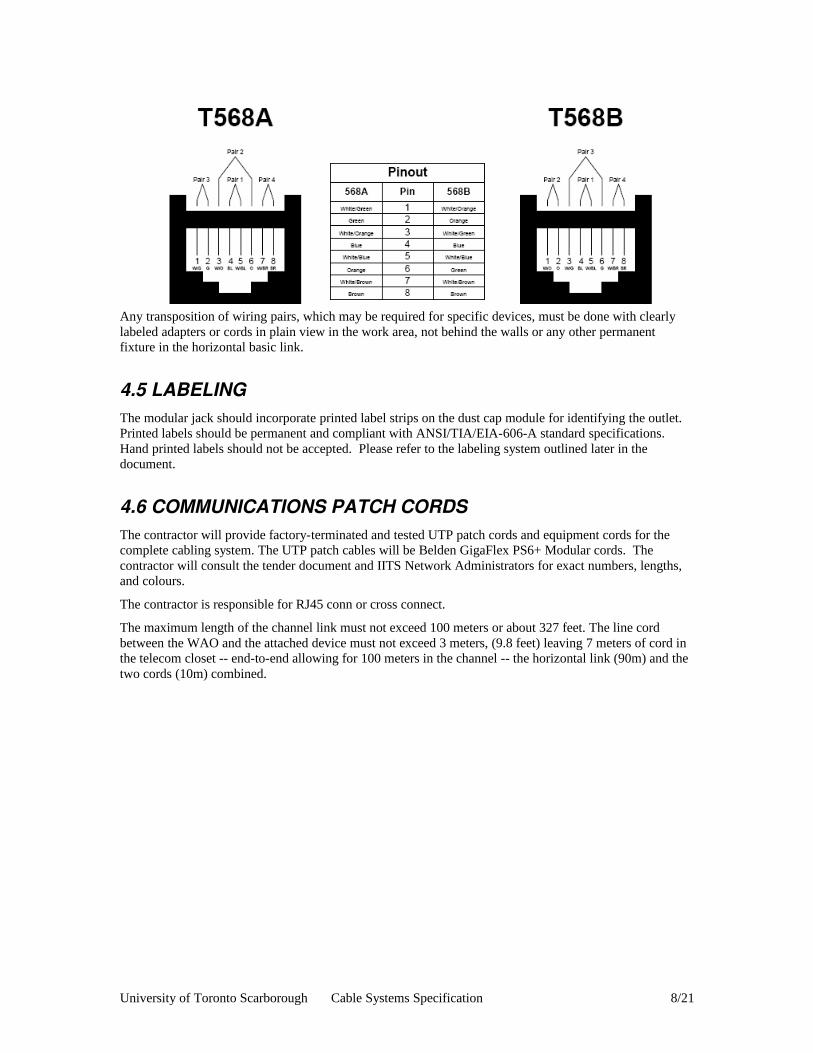
Any transposition of wiring pairs, which may be required for specific devices, must be done with clearly labeled adapters or cords in plain view in the work area, not behind the walls or any other permanent fixture in the horizontal basic link.
4.5 LABELINGThe modular jack should incorporate printed label strips on the dust cap module for identifying the outlet. Printed labels should be permanent and compliant with ANSI/TIA/EIA-606-A standard specifications. Hand printed labels should not be accepted. Please refer to the labeling system outlined later in the document.
4.6 COMMUNICATIONS PATCH CORDSThe contractor will provide factory-terminated and tested UTP patch cords and equipment cords for the complete cabling system. The UTP patch cables will be Belden GigaFlex PS6+ Modular cords. The contractor will consult the tender document and IITS Network Administrators for exact numbers, lengths, and colours.
The contractor is responsible for RJ45 conn or cross connect.
The maximum length of the channel link must not exceed 100 meters or about 327 feet. The line cord between the WAO and the attached device must not exceed 3 meters, (9.8 feet) leaving 7 meters of cord in the telecom closet -- end-to-end allowing for 100 meters in the channel -- the horizontal link (90m) and the two cords (10m) combined.
University of Toronto Scarborough Cable Systems Specification 8/21

4.7 COLOUR CODE FOR PATCH CORDS
Usage Category Colour
Equipment Belden PS6+ Green
PoE Devices Belden PS6+ Black
Voice (Non-PoE) Belden PS6+ White
**DEPRECATED** Belden PS5+ Blue
5.0 HORIZONTAL CABLING
5.1 DESIGNAll horizontal channels must contain only Belden IBDN System 4800 components, including cables, jacks, patch cords, patch panels, cross-connects, and workstation outlets. In most circumstances the cable must be Plenum Rated (CMP – DataTwist 4813). However if allowed by code, and explicitly allowed in the tender, Riser Rated cable my be used (CMR – DataTwist 4812). All cable MUST be WHITE in color.
5.2 CABLE LENGTHThe maximum allowable distance from the patch panel in the Telecommunications Closet or TC to the Work Area Outlet is 90 meters (295 feet). This should be taken into account when identifying the size of a TC service area.
University of Toronto Scarborough Cable Systems Specification 9/21

5.3 CABLE SUPPORTCare should be taken when initial designs for a TC service area are engineered, not to under-size this critical segment of the horizontal system. Retrofitting an existing occupied building to support more horizontal cabling, if it is possible at all, is expensive to implement in every way, from engineering design through installation.
Cable pathways are to be in straight lines with as few turns as possible. In all instances every effort should be made to have these pathways parallel and in proximity to public spaces (such as hallways). This makes it easy for access and minimizes workers downtime due to technicians within the work area. Cable Tray or a combination can be used to support cable between the WAO and TC. In locations where large cable quantities exist, cable tray should be used.
If cable trays are not appropriate or feasible conduit is to be used. J-Hooks are only to be used when explicitly called for in a tender.
Under no circumstances should horizontal cable be run unsupported, or supported by any other method other than listed in this document.
5.4 CABLE TIESCable containment is the purpose of cable ties, to manage, organize and control large amounts of cable. Cable ties are widely used to bundle cable in manageable groups during each phase of installation. When applied too tight they change the physical characteristics of the cable, resulting in degraded electrical performance. The proper use of cable ties is the focus of installing horizontal cable. Sections, Design and Installation, touch on similar topics with this section answering the “whys” of cable ties, and Installation “hows.”
U of T Scarborough requires loose cable ties! Ties, preferably Velcro or Millie-Tie™ should be installed so that they loosely wrap around the bundle and one finger can be slipped inside the cable and the tie.
In addition, the application of the cable ties during preliminary phases of installation can compress the cable to the point of bending the conductors inside each cable facing out in the group. Care must be taken during early phases of work to not damage the cables. This has a detrimental affect in High speeds.
5.5 BUNDELINGContainment is the goal of organizing, managing and dressing the cable bundle through the support system. Cat 6 cables are engineered to have airspace in and around each cable. The random lay of the cable in the support system ensures there is minimal electrical influence between energized cables. A nice, clean “computer room showcase” bundle of cable is not the goal, due to the physical changes tight bundles exert on the cable. In Illustration 1 the cable is one large tightly groomed bundle, with the entire weight of the bundle suspended from the cable tray above. This removes the airspace and the random lay of the cable, increasing the potential of electrical influence between adjacent cables.
University of Toronto Scarborough Cable Systems Specification 10/21

5.6 CABLE TOPOLOGYHorizontal wiring must be configured in a star topology, with each WAO directly connected to the TC. The horizontal wiring should not contain any discontinuities, such as Consolidation Points, between the TC and the WAO ("home run" method). Splices or bridge taps are not permitted in the horizontal cabling.
Cable part numberRiserPlenumPlenum when necessary as per fire codePart numbers
6.0 TELECOMMUNICATIONS CLOSET
6.1 DESIGNBecause of the highly specialized nature of the computer center, along with its function and location in the enterprise and the hosting site LAN infrastructure, the space is identified as a TR (telecommunications room.)
For new and retrofitted TRs field cables will be terminated in a Belden/IBDN GigaBIX block. The field cables will be cross-connected to another GigaBIX block, and pig-tails will be run through the cable
University of Toronto Scarborough Cable Systems Specification 11/21
Illustration 1: DO NOT DO THIS!

management and terminated to length. Do not insert any network cables into network equipment, instead inform the Network Administrators when the work is complete.
In older, non-retrofitted, TRs, field cables will be terminated with MDVO jacks and placed into GigaFlex captured patch panels. Refer to the tender or explicit direction from the Network Administrators for exact details when working in these spaces.
6.2 GigaBix SYSTEMAll new network and telephone cables will be terminated in Belden/IBDN GigaBIX 72 port mounts(AX101472) inside the Telecommunications Closets (TC). The GigaBIX will be in a “Cross-Connect” layout. The cables will be cross-connected, and pig-tails will be installed, and labeled, into the cable management of the network equipment cabinets. If analogue phone lines are to be used, the regular BIX block will be installed on the wall as near to the GigaBIX as possible to facilitate cross-connections.
All GigaBIX installations will have cable management modules(AX101469) installed to provide a false wall for easier cable management and routing of cables. In between all GigaBIX panels a GigaBIX management ring(AX10178) will be installed to manage the cross connect wires this ring should be sufficient to manage 450 cross connect wires. GigaBIX retainer(AX101486) will be installed to protect connections from slipping out. Termination bars(AX101719) will be installed on all cables to prevent misalignment and unneeded pair untwisting.
In older existing TCs the contractor will contact the administrators for instructions on what method to use to terminate cables in telecommunication room.
6.3 CABLE MANAGEMENT AND RACKSUTSC has a standard rack that is available from Anixter, part numbers and details will be specified in the tender.
6.4 UPS AND EMERGENCY POWERPower also should be conditioned and backed up. These should be worked out with an electrician and the local Site Facilities Manager to find the most economical solution based on price, space, maintenance and usability. Possible solutions are local UPS, building UPS, generators or a combination of both. A list of equipment that is critical must be put together to size the units. A growth factor for future equipment should also be considered. UPS and Emergency power are required to support the installation of redundant power supplies.
6.5 GROUNDINGGrounding to the nearest pipe or structural steel is not acceptable. A separate telecommunications grounding system should be installed within the space and connected to the main building ground. The electrician shall provide a ground bus bar connected to the telecom ground system in each closet. It is the cabling contractor’s responsibility to attach the telecom equipment to the bar. All contractors shall provide grounding & bonding in accordance with good industry practices and in accordance with the following codes and standards.
– CSA Standard C22.2 No.41-M1987 – Grounding & Bonding Equipment– CSA Standard T527 (ANSI/TIA/EIA-607)– CSA Standard T 530 - Telecommunications Pathways and Spaces– Ontario Hydro Electrical Safety Code– Ontario Building Code– Local Codes & Bylaws– BICSI requirements
University of Toronto Scarborough Cable Systems Specification 12/21
7.0 INTERBUILDING AND INTERCAMPUS BACKBONE CABLING
7.1 DESIGNInter-Campus Backbone will consist of two (2) 144-fiber single-mode cables running in paths as geographically diverse as possible. One(1) cable will be terminated in the campus data centre, one(1) cable will be terminated in a TR designated as the Campus Backbone Demarcation. In the case where a campus does not have a data centre there will be two (2) geographically diverse Campus Backbone Demarcation location.
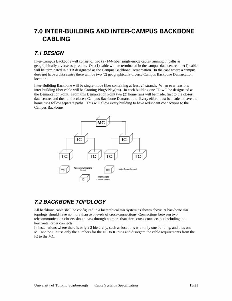
Inter-Building Backbone will be single-mode fiber containing at least 24 strands. When ever feasible, inter-building fiber cable will be Corning Plug&Play(tm). In each building one TR will be designated as the Demarcation Point. From this Demarcation Point two (2) home runs will be made, first to the closest data centre, and then to the closest Campus Backbone Demarcation. Every effort must be made to have the home runs follow separate paths. This will allow every building to have redundant connections to the Campus Backbone.
7.2 BACKBONE TOPOLOGYAll backbone cable shall be configured in a hierarchical star system as shown above. A backbone star topology should have no more than two levels of cross-connections. Connections between two telecommunication closets should pass through no more than three cross-connects not including the horizontal cross connects. In installations where there is only a 2 hierarchy, such as locations with only one building, and thus one MC and no ICs use only the numbers for the HC to IC runs and disregard the cable requirements from the IC to the MC.
University of Toronto Scarborough Cable Systems Specification 13/21

8.0 BUILDING BACKBONE CABLING
8.1 DESIGNFrom the TR designated as the building Demarcation Point to all other TR, there will be fiber optic cables run. Unless explicitly allowed by the tender, daisy-chaining of one TR to another is not allowed.
8.2 FIBEROPTICAll in building fiber-optic cabling will contain only Corning Plug&Play(tm) products including, but not limited to, glass, trunk cables, zip-cords, patch cables, modules, harnesses, jumpers, shelves, and housings.
Each TR will be connected to the building Demarcation Point by one (1) 12-strand single-mode, and one (1) 12-strand multi-mode Plug&Play(tm) Universal Systems MTP(r) Connector Trunk.
8.3 COPPERCopper cabling is not allowed for building backbone cabling.
9.0 PATHWAYS AND SPACEOverhead cabling is the preferred method of cable distribution at the University of Toronto Scarborough campus. When designing the cable tray system, the tray should not exceed the TIA’s recommended fill ratio of 40%. The University would like to see installations consisting of CABLOFIL tray manufactured by CABLOFIL/Legrand.
University of Toronto Scarborough Cable Systems Specification 14/21

10.0 CABINETS AND RACKS UTSC has a standard rack that is available from Anixter, part numbers and details will be specified in the tender.
11.0 ADMINISTRATION
11.1 LABELINGThe Cable Contractor, per the examples given in this document, will provide and install labels.
All labeling should be unique across the entire wiring infrastructure within a building and between buildings on a campus.
As stated earlier in the document, each label shall be self-adhesive with 10 or 12-point black printing on a white background.
Labeling tags and markings should be permanent enough to last the life of the component to which it is attached. This can range from a few years for telecom equipment up to 50 years for parts of the building such as closets and pathways. Cables should be labeled at both ends and use the same alphanumeric identifiers.
A well-administered cabling infrastructure can save time, money and frustration when dealing with trouble calls, maintenance, moves adds and changes, and new installations. It’s important to keep it well documented and maintained.
11.2 WORK AREA AND HORIZONTAL CABLE LABELINGCable and WAO labels will be as follows:
<TR Designation>-<Room #>-<punch down location>
Where:
TR Designation : is a 2 or 3 character identifier for the TR in which the horizontal cable is terminated.
Room # : is the official room number for the Work Area where the horizontal cable is coming from
Punch Down Location: contains 1 letter identifying the patch panel of gigabix block in the TR, and 2 digits indicating which position the cable is in. (01-24 or 01-48 in the case of a patch panel, or 01-72 in the case of a GigaBIX block)
Examples:
5R-551-E06: A cable starting in room 551 and terminated in telecom room 5R, patch panel E, jack 6
3A-427B-C70: A cable starting in room 427B and terminated in telecom room 3A, GigaBIX block C, position 70
11.3 PIGTAIL LABELINGEach pig-tail will be labeled with the Punch Down Location as specified in the previous section.
University of Toronto Scarborough Cable Systems Specification 15/21
11.4 PATCH PANEL AND GIGABIX LABELINGPatch panels and GigaBIX blocks must have labels affixed that correspond with the horizontal cable or pig-tail terminated at that position.
11.5 TELECOMMUNICATIONS CLOSETEach rack in each closet shall be labeled from 1 to 6. The rack in the front row on the left is rack 1 and proceeds to the right. The left most rack in row 2 (if a second row is present) continues with the numbering sequence until a maximum of 6.
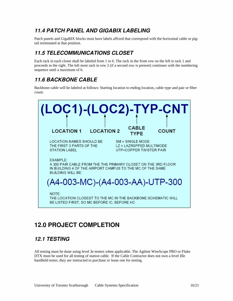
11.6 BACKBONE CABLEBackbone cable will be labeled at follows: Starting location to ending location, cable type and pair or fiber count.
12.0 PROJECT COMPLETION
12.1 TESTING
All testing must be done using level 3e testers when applicable. The Agilent WireScope PRO or Fluke DTX must be used for all testing of station cable. If the Cable Contractor does not own a level IIIe handheld tester, they are instructed to purchase or lease one for testing.
University of Toronto Scarborough Cable Systems Specification 16/21

12.1.1 COPPER CABLEAll cable station channels from the outlet patch cord to the data room patch cord must be tested to the specifications below. All Copper connections must be tested as an entire channel, including a patch cord in the data room and a patch cord at the station, as well as the proper SYSTIMAX probes as required. Test results must show a pass of all the following parameters specified below, as well as wire map. Testing must be done on a tester that performs the tests below from 1-500 MHz. Channel must meet the following requirements: Maximum Length: 328 feet The following electrical characteristics
12.1.2 FIBEROPTIC CABLEAll fiber optic cable links must be tested with a source and meter. The test results must include the loss generated by each connector. Loss should be stated in dB. No fiber optic link will be accepted with a loss greater than the calculated value based on the table below.
University of Toronto Scarborough Cable Systems Specification 17/21

Example a link with 3 connectors and a total length of 500m should have a maximum attenuation of 2.35dB at 850nm and 1.35dB at 1300nm
All Outside Plant fiber must be traced with an OTDR after installation to ensure compliance and results must be provided to the customer in both paper and computer copy.
12.2 TEST RESULT DOCUMENTATIONThe test result information for each link shall be recorded in the memory of the field tester upon completion of the test. The test result records saved by the tester shall be transferred into a Windows™-based database utility that allows for the maintenance, inspection and archiving of these test records. A guarantee must be made that these results are transferred to the PC unaltered, i.e., “as saved in the tester” at the end of each test. The popular ‘csv’ format (comma separated value format) does not provide adequate protection and shall not be acceptable.
The database for the completed job – including twisted-pair copper cabling links if applicable –shall be stored and delivered on CD-ROM; this CD-ROM shall include the software tools required to view, inspect, and print any selection of test reports. A soft copy of the test results shall be provided that lists all the links that have been tested with the following summary information
1. The identification of the link in accordance with the naming convention defined in the overall system documentation
2. The overall Pass/Fail evaluation of the link-under-test including the Attenuation worst case margin (margin is defined as the difference between the measured value and the test limit value).
The date and time the test results were saved in the memory of the tester
General Information to be provided in the electronic data base containing the test result information for each link:
a. The identification of the customer site as specified by the end-user
University of Toronto Scarborough Cable Systems Specification 18/21

b. The overall Pass/Fail evaluation of the link-under-test
c. The name of the standard selected to execute the stored test results
d. The cable type and the value of the ‘index of refraction’ used for length calculations
e. The date and time the test results were saved in the memory of the tester
f. The brand name, model and serial number of the tester
g. The revision of the tester software and the revision of the test standards database in the tester Test results must be submitted to the owner in electronic format. Electronic results must be presented with a copy of the electronic software used to generate the test results.
The detailed test results data to be provided in the electronic database for each tested optical fiber must contain the following information
a. The identification of the link/fiber in accordance with the naming convention defined in the overall system documentation
b. The insertion loss (attenuation) measured at each wavelength, the test limit calculated for the corresponding wavelength and the margin (difference between the measured attenuation and the test limit value).
c. The link length shall be reported for each optical fiber for which the test limit was calculated based on the formulas in TIA568B section B.3.
13.0 PRODUCTSThe Cabling Contractor will provide and install all items necessary, stated herein or not, to furnish the owner with a functional telecommunications cabling system. The materials list, stated herein, does not contain everything needed to complete a structured cabling system. Bidders are assumed to have tools to complete the job and to have a certain amount of "consumables" such as nuts, breakout kits, epoxy etc. It is the contractor’s responsibility to have everything needed to complete the job to the spirit of this specification and adhere to the manufacturer's guidelines.
13.1 CABLE RUNWAY – TELECOM ROOMCABLOFIL/Legrand CABLOFIL – Part number selection and mounting options will depend on the application, location and cable volume. Overhead cable pathways are the preferred method of cable distribution.
13.2 COPPER HORIZONTAL SUPPORT TRAYCABLOFIL/Legrand CABLOFIL – Part number selection and mounting options will depend on the application, location and cable volume. Overhead cable pathways are the preferred method of cable distribution.
Wiremold Raceway systems - Part number selection and mounting options will depend on the application, location and cable volume. Plastic or metal raceway can be used depending on the application. Metal raceway is preferred in applications involving power and separate channels should be built into the design to accommodate power and data cabling.
University of Toronto Scarborough Cable Systems Specification 19/21
13.3 RELAY RACKS AND CABINETSUTSC has a standard rack that is available from Anixter, part numbers and details will be specified in the tender.
13.4 COPPER CABLETWISTED PAIR (COPPER) STANDARDS – ALL CABLE SHALL MEET THE REQUIREMENTS OF TIA/EIA568-B.2.All horizontal channels must contain only Belden IBDN System 4800 components, including cables, jacks, patch cords, patch panels, cross-connects, and workstation outlets. In most circumstances the cable must be Plenum Rated (CMP – DataTwist 4813). However if allowed by code, and explicitly allowed in the tender, Riser Rated cable my be used (CMR – DataTwist 4812). All cable MUST be WHITE colour.
13.4.1 COPPER TERMINATIONSAll Copper terminations should be done using Modular Jacks, in the case of an old TR or at a WAO, or in Belden GigaBIX blocks, in the case of all new and retro-fitted Trs. Icons will be used to distinguish Voice and Data connections
13.4.2 PATCH PANELSThe use of patch panels is now DEPRECATED except where explicitly listed in the tender and only in TR spaces with no GigaBIX componenets.
13.4.3 COPPER PATCH CORDSThe UTP patch cables will be Belden GigaFlex PS6+ Modular cords. The contractor will consult the tender document and IITS Network Administrators for exact numbers, lengths, and colours.
The maximum length of the channel link must not exceed 100 meters or about 327 feet. The line cord between the WAO and the attached device must not exceed 3 meters, (9.8 feet) leaving 7 meters of cord in the TR -- end-to-end allowing for 100 meters in the channel -- the horizontal link (90m) and the two cords (10m) combined.
13.5 FIBEROPTIC CABLEFIBER-OPTIC STANDARDS – ALL CABLE SHALL MEET THE REQUIREMENTS OF TIA/EIA568-B.3.
– All proposed fiber-optic cabling will contain only Corning products including, but not limited to, glass, trunk cables, zip-cords, patch cables, modules, harnesses, jumpers, shelves, and housings.
– All cable and fiber that originate or terminate in the computer room must be plenum rated excluding jumper cords.
– All fiber runs must be installed in plenum rated innerduct or conduit. – All fiber-optic cable will be single-mode or OM3+ (Corning LANscape Pretium(r) 300) multi-
mode cables installed in the building backbone. The distribution panels and fiber ends will be LC connector/couplers as specified in the standard unless specified on the detailed drawings or in the case of preterminated solution that use factory terminated MTP(r) ends.
– No cable may be run under-floor unless explicitly called for.– Every run is either Corning ALTOS(r) or FREEDM(r) for inter-campus backbone cable, or
Corning Plug&Play(tm) Universal Systems for inter-building and in building backbone cable
University of Toronto Scarborough Cable Systems Specification 20/21

13.5.1 FIBER OPTIC TERMINATIONS– The fiber optic connectors must be either field installable single-mode connectors, in the case of
inter-campus backbone cable, or factory terminated MTP(r) connectors– The connector shall provide a strain relief mechanism for installation on a single fiber cable that
contains strength elements. The fiber within the body of the connector shall be isolated– Mechanically from cable tension bending and twisting.– The connector shall have a ceramic ferrule and a factory PC polish.– The connector must have a locking feature to the coupler.– Meet EIA and IEC standards for repeatability.
Required connectors are Corning Unicam LC Fiber Optic Connectors for field-terminated cable and Corning MTP(r) for factory terminated cable.
13.6 GROUNDINGContractors should follow the TIA/EIA 607 grounding standard for all Closet/Computer Room/Data center installations
13.7 UPSAPC UPS are the preferred devices for back up power. Please consult with the university’s IT professionals to confirm sizing and product selections.
University of Toronto Scarborough Cable Systems Specification 21/21