utl series - farnell element14 · iec 60598 & ul 1598 ul/iec 60950 uscar2 ul 1995 utl series...
TRANSCRIPT
UTL SeriesDynamic IP68/69K • UV Resistant • UL/IEC Compliant
Connection Technologies


3© 2013 – SOURIAU
Contents
UTL Series
Interact safety standards ............................................. 06
UTL range overview ..................................................... 07
General technical characteristics ............................. 10
Overview
Specifi cations ................................................................... 14
Harnesses ........................................................................ 14
Dimensions ..................................................................... 15
Accessories & tooling .................................................. 16
Contacts ........................................................................... 17
Evaluation kit ................................................................... 18
Mechanics
Description ...................................................................... 20
Contact plating selector guide .................................. 21
Contact selector guide ................................................ 22
Packaging ........................................................................ 22
Crimp contacts ............................................................... 23
#16 coaxial contacts ................................................... 24
Contacts
Tooling .............................................................................. 28
Crimptooling table ........................................................ 29
Extraction tools .............................................................. 29
Handle & Interchangeable Heads ............................ 30
Assembly instruction .................................................... 31
Cable assembly .............................................................. 37
Dimensions mated connector ................................... 40
Rated current & working voltage .............................. 41
UV resistance ................................................................. 41
UL94 ................................................................................. 42
UL1977 ............................................................................ 43
IEC 61984 with IP code explanation ...................... 45
What is NEMA rating ? ................................................ 47
Technical information
#16 coaxial contacts - cabling notices .................. 50
Glossary of terms .......................................................... 57
Part number Index.......................................................... 58
Appendices
Ap
pe
ndic
es
Tech
nica
l inf
orm
atio
nC
ont
acts
Mec
hani
csO
verv
iew

UT
LS
erie
s

5© 2013 – SOURIAU
OverviewUTL Series
Interact safety standards .............................................................................................................. 06
UTL range overview ...................................................................................................................... 07
General technical characteristics .............................................................................................. 10

6 © 2013 – SOURIAU
Connector
UL 201
Connector
IEC
619
84
- I
EC 6
03
09
Interact safety standardsMarket Market
UL 1977: Component connectors for use in data, signal, control and power applications
UL 2238: Cable assemblies and fi ttings for industrial control and signal distribution
UL/IEC 60950: Information technology equipment
IEC 61984: Connectors
IEC 60601: Medical equipmentUScar2: Performance specifi cation for automotive electrical connector systems
IEC 60309: Plugs, socket-outlets and couplers for industrial purposes
IEC 61010: Safety requirements for electrical equipment for measurement, control, and laboratory use
UL 498: Attachment plugs and receptacles
UL 1995: Heating and cooling equipment
UL 201: Garage equipment
IEC 60598: Street lights
UL
49
8 -
UL
1977
ApplicationsFinger probe test Flame retardant Stress relief test
Finger probe testFlame retardantStress relief test
Dynamic impact test
Hot wire test
Stress relief testImpact test
Finger probe testAgeing test
Finger probe test
Cold testBending (fl exing) testCorrosion resistance
Finger probe test
Corrosion resistance
Finger probe test
UL 2238
IEC 60601
IEC 61010
IEC 60598 & UL 1598
UL/IEC 60950
UScar2
UL 1995
UTL SeriesOverview
In today fast paced environment we are all buying electronic devices withconfi dence. To achieve a high such level of trust, the legislator had to put inplace a wide variety of safety standards.Being conscious of the number of standards and the diffi culty to fi nd anappropriate connector, Souriau decided to release an all-in-one solution.The UTL series is a unique connector which is compliant with ALL industry standards you can see nowadays.In addition to this it has been designed to be exclusively overmolded preventunwanted tamper. Souriau having the ability to supply cable assemblies it istherefore a gain of time with a one stop shopping supplier. There is no needanymore to look for a cable house able to terminate this fantastic product.

7© 2013 – SOURIAU
UTLrange overview
The philosophy of the UTL Series is built around three key elements:
Dynamic IP68/69K UV Resistant UL/IEC Compliant
In most applications, our connectors areexposed to extreme climatic conditions; it was therefore key for us to select thematerials best able to cope with thetargeted environment.
Part of our product qualifi cation processinvolved subjecting connectors to asimulated fi ve years of exposure to various elements including Temperature, UV and Humidity.
The UTL Series uses an outdoor rated material. Underwriters Laboratories classifi es it "F1" per UL746C.
The outmost priority for any electricalinstallation is to protect personnel from any shock hazard.
In North America, Underwriters Laboratories insisted that connector manufacturers,depending of the application, respect their standards. The UTL Series had thus been qualifi ed, certifi ed by thisorganisation and compliant with the UL 1598, UL1977, UL498, UL60320.
In Europe and in Asia, IEC standards are better known and trusted by end users. Like its American equivalent, the IEC refers to safety rules. The UTL Series was obviously designed to respect these rules and especially the IEC 60598, IEC60065, IEC60320, IEC61076-2-103.
The UTL Series is rated at IP68/69K… even in dynamic conditions. This means that it remain sealed even when usedcontinuously underwater or cleaned usinga high pressure hose and cable is moving.
If this same level of performance is required even when connectors then we have special sealed contacts. This unique fetaure helps you to product your electronics from ingress of water. This is particulary insteresting when using with NEMA enclosure or outdoor luminaires.
UTL SeriesOverview
The stainless steel latch coupling system makes it simple to use.With only 1 fi nger, connectors are mated with an audible and sensitive “click”.The key shape of the coupling system makes it blind mateable. In dark conditions the color and mechanical discriminations helps you to do it and avoid you to damage connectors.
The UTL Series is a plastic connector range designed to respect modern safety standards.
Ove
rvie
w
8 © 2013 – SOURIAU
UTL Series
UTL SeriesOverview
Free hanging plug
Free hanging plug
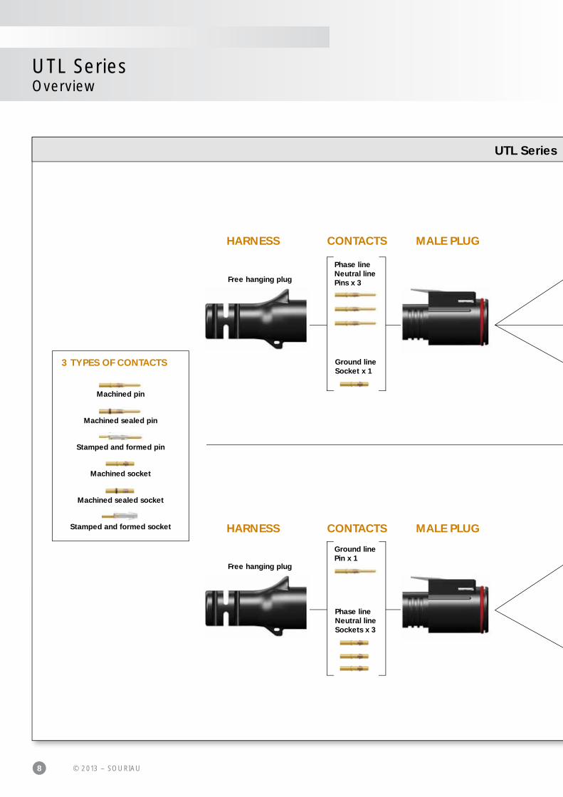
Machined pin
Machined sealed pin
Stamped and formed pin
Machined socket
Machined sealed socket
Stamped and formed socket
3 TYPES OF CONTACTS
Phase lineNeutral linePins x 3
Ground linePin x 1
Ground lineSocket x 1
Phase lineNeutral lineSockets x 3
MALE PLUG
MALE PLUG
CONTACTS
CONTACTS
HARNESS
HARNESS

9© 2013 – SOURIAU
range overview
UTL SeriesOverview
Jam nut
Jam nut
Jam nut
Jam nut
Square flange
Square flange ACCESSORIES
ACCESSORIES
Free hanging receptacle
Free hanging receptacle
Phase lineNeutral lineSockets x 3
Ground linePin x 1
Phase lineNeutral linePins x 3
Ground lineSocket x 1
FEMALE RECEPTACLES CONTACTS
CONTACTSFEMALE RECEPTACLES HARNESS
HARNESS
Ove
rvie
w

10 © 2013 – SOURIAU
2
4
General technical
3
UTL SeriesOverview
Mechanical
• Durability: 500 matings & unmatings (with stamped and formed contact, S18 plating or with machined contact, K plating)
• Coupling system: - Sensitive and audible click - Blind mateable
• Touchproof : IP2X in unmated conditions (connector equipped with socket contacts)
1
Environmental
• Operating temperature: From -40°C to +105°C for connector From -20°C to +60°C for harness due to HO7RNF cable performances
• Flammability rating: UL 94 5VA
• Salt spray: 1000 hours
• UV resistant: No mechanical degradation or important variation of colour of exposure in natural environment (F1material per the UL 746C)
• Sealing: - IP68/69K mated with standard contacts - IP68 even unmated with sealed contacts (see p23)
• Fluid resistance: - Gasoil - Mineral oil - Acid bath - Basic bath
3
4

11© 2013 – SOURIAU
characteristics
1
UTL SeriesOverview
Qualifi cation • In accordance with: - IEC60065, IEC60598, UL1598, IEC60320, UL498, UL94 , UL746 , IEC61076-2-103 - UL 1977: UL fi le number E169916 - IEC 61984: Pending
Material
• Body connector + Backshell: Thermoplastic
• Insert connector: Thermoplastic
• Contacts: See page 20
• Nut: Metal
• Halogen free
• RoHS compliant & conform to the Chinese standard SJ/T1166-2006 (Chinese RoHS equivalent)
Electrical
• UL: 600V 16A UL94 5VA 277V 13A for CBC use
• CN: 600V 13A 277V 10A for CBC use
• IEC: 16A 500V 6KV 4 13A 250V 4KV 4 for CBC use
• Connector specially designed to be engaged or disengaged in normal use when live or under load
• First Mate Last Break contact mating on earth line2
Ove
rvie
w

UT
LS
erie
s

13© 2013 – SOURIAU
MechanicsUTL Series
103G1
Specifi cations ................................................................................................................................... 14
Harnesses ......................................................................................................................................... 14
Dimensions ...................................................................................................................................... 15
Accessories & tooling ................................................................................................................... 16
Contacts ............................................................................................................................................ 17
Evaluation kit .................................................................................................................................... 17
14 © 2013 – SOURIAU
OR OR
WITH
0 20 40 60 80 100 1200
13
10
18
30
28Current (A)
Ambient Operating Temperature (°C)
20
23
25
3
8
5
15
UTL Series103G1
LayoutLayout
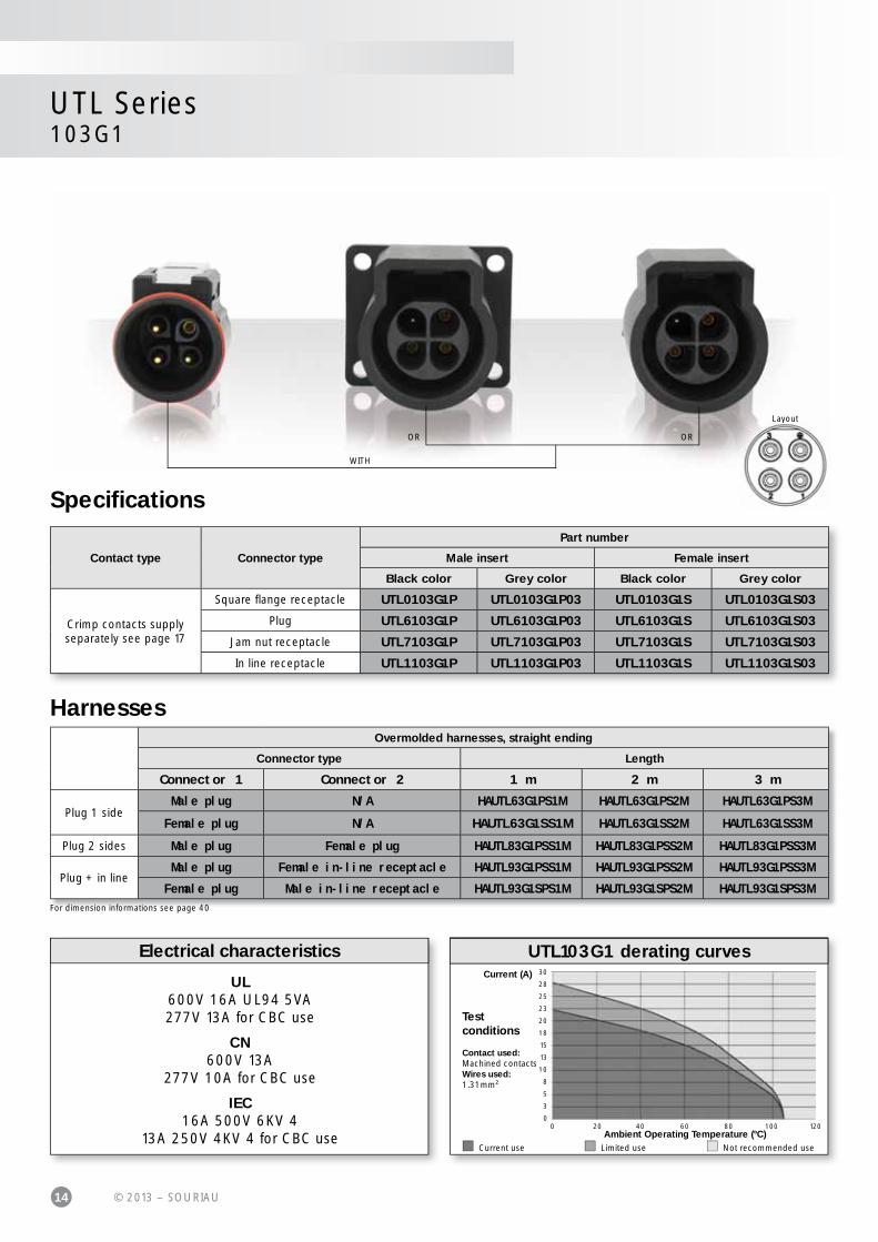
Specifi cations
UL600V 16A UL94 5VA277V 13A for CBC use
CN600V 13A
277V 10A for CBC use
IEC16A 500V 6KV 4
13A 250V 4KV 4 for CBC use
UTL103G1 derating curvesElectrical characteristics
Testconditions
Contact used:Machined contactsWires used:1.31mm²
Current use Limited use Not recommended use
Overmolded harnesses, straight ending
Connector type Length
Connector 1 Connector 2 1 m 2 m 3 m
Plug 1 sideMale plug N/A HAUTL63G1PS1M HAUTL63G1PS2M HAUTL63G1PS3M
Female plug N/A HAUTL63G1SS1M HAUTL63G1SS2M HAUTL63G1SS3M
Plug 2 sides Male plug Female plug HAUTL83G1PSS1M HAUTL83G1PSS2M HAUTL83G1PSS3M
Plug + in lineMale plug Female in-line receptacle HAUTL93G1PSS1M HAUTL93G1PSS2M HAUTL93G1PSS3M
Female plug Male in-line receptacle HAUTL93G1SPS1M HAUTL93G1SPS2M HAUTL93G1SPS3M
Harnesses
For dimension informations see page 40
Contact type Connector type
Part number
Male insert Female insert
Black color Grey color Black color Grey color
Crimp contacts supplyseparately see page 17
Square fl ange receptacle UTL0103G1P UTL0103G1P03 UTL0103G1S UTL0103G1S03
Plug UTL6103G1P UTL6103G1P03 UTL6103G1S UTL6103G1S03
Jam nut receptacle UTL7103G1P UTL7103G1P03 UTL7103G1S UTL7103G1S03
In line receptacle UTL1103G1P UTL1103G1P03 UTL1103G1S UTL1103G1S03

15© 2013 – SOURIAU
UTL Series103G1
Dimensions
Note: all dimensions are in mm
3 + ground16A/250-500V
per IEC 61984
In line receptacle - UTL1Square fl ange receptacle - UTL0Ø
18
28
.6
33.630
12
Ø3.2Front view Front view
Front view
Front view
20
2015.5
22.2
30
3026.6 11.3 14
28
.62
8.6
23
.7
Ø15
.5
Jam nut receptacle - UTL7Plug - UTL6
Panel cut out
21
.8
26.7
Ø3.3
Jam nut receptacle - UTL7
16
.45
Ø2
2.2
9.4
Ø17.2
Square fl ange receptacle - UTL0
Ø18.3
1.45
Mec
hani
cs

16 © 2013 – SOURIAU
Crimp tooling
Contacts Contact sizePart number
of head
RM/RC 28M1K(1)
Standard contacts
#16Ø 1.6mm
S16RCM20
RM/RC 24M9K(1) S16RCM20
RM/RC 20M13K(1) S16RCM20
RM/RC 20M12K(1) S16RCM20
RM/RC 16M23K(1) S16RCM16
RM/RC 14M30K(1) S16RCM14
RM/RC 16M25K S16RCM1625
RM/RC 14M25K S16RCM1425
SM/SC 24ML1TK6(1) S16SCM20
SM/SC 20ML1TK6(1) S16SCM20
SM/SC 16ML1TK6(1) S16SCML1
SM/SC 14ML1TK6(1) S16SCML1
SM/SC 16ML11TK6(1) S16SCML11
RMDXK10D28K
Coaxial contacts
M10S-1J
RCDXK1D28K M10S-1J
RM/RC DX60xxD28K M10S-1J
RM/RC DXK10D28 + york090 M10S-1J
RM/RC DX60xxD28 M10S-1J(1): example of plating, for other plating see UTL catalog page 22
Accessories
UTL Series103G1
Dustcap for plug
Dustcap for maleplug UTL0/1/6
Dustcap for receptacle
Dustcap for femaleplug UTL0/1/6
Part number
UTL610DCG
Part number
UTL103G1PDCG68
Part number
UTL10DCG
Part number
UTL103G1SDCG68
Grommet
Part number
SWSFILLERPLUG
IP67
IP68/69K IP68/69K
IP67
See instruction page 36
Handle
Part number
SHANDLES
Tooling

17© 2013 – SOURIAU
3 + ground16A/250-500V
per IEC 61984
UTL Series103G1
Contacts
#16 Contact type AWGPart number Max
wire ØMax
insulator ØMale Female
Cri
mp
Machined
30-28 RM28M1K(1) RC28M1K(1) 0.55 1.1
26-24 RM24M9K(1) RC24M9K(1) 0.8 1.6
22-20 RM20M13K(1) RC20M13K(1) 1.18 1.8
22-20 RM20M12K(1) RC20M12K(1) 1.18 2.2
20-16 RM16M23K(1) RC16M23K(1) 1.8 3.2
16-14 RM14M30K(1) RC14M30K(1) 2.28 3.2
Machined with o-ring20-16 RM16M25K(3) RC16M25K(3) 1.8 3.2
16-14 RM14M25K(3) RC14M25K(3) 2.28 3.2
Stamped & formedreeled contacts
26-24 SM24ML1TK6(1)(2) SC24ML1TK6(1)(2) 0.89-1.28 -
22-20 SM20ML1TK6(1)(2) SC20ML1TK6(1)(2) 1.17-2.08 -
18-16 SM16ML1TK6(1)(2) SC16ML1TK6(1)(2) 3.0 -
18-16 SM16ML11TK6(1)(2) SC16ML11TK6(1)(2) 2.0-3.0 -
14 SM14ML1TK6(1)(2) SC14ML1TK6(1)(2) 3.2 -
Co
axia
l
Cable Multipiece - RMDXK10D28 RCDXK1D28 - -
Cable Monocrimp - RMDX60xxD28 RCDX60xxD28 - -
Twisted pair Multipiece -RMDXK10D28 +
york090RCDXK1D28 +
york090- -
Twisted pair Monocrimp - RMDX60xxD28 RCDX60xxD28 - -
Note: all dimensions are in mm
(1): Example of plating, for other plating see page 22(2): To obtain contact reeled remove L in part number. Example: SM20M1TK6(3): Sealed contacts
Evaluation kit - See instructions page 35
Connector type Wire section BootPart number
Male insert Female insert
Plug
AWG 20 1 UTL6103G1P20AWG UTL6103G1S20AWG
AWG16 1 UTL6103G1P16AWG UTL6103G1S16AWG
AWG14 1 UTL6103G1P14AWG UTL6103G1S14AWG
Inlinereceptacle
AWG 20 1 UTL1103G1P20AWG UTL1103G1S20AWG
AWG16 1 UTL1103G1P16AWG UTL1103G1S16AWG
AWG14 1 UTL1103G1P14AWG UTL1103G1S14AWG
Jam nutreceptacle
AWG 20 - UTL7103G1P20AWG UTL7103G1S20AWG
AWG16 - UTL7103G1P16AWG UTL7103G1S16AWG
AWG14 - UTL7103G1P14AWG UTL7103G1S14AWG
Square fl angereceptacle
AWG 20 - UTL0103G1P20AWG UTL0103G1S20AWG
AWG16 - UTL0103G1P16AWG UTL0103G1S16AWG
AWG14 - UTL0103G1P14AWG UTL0103G1S14AWG
NB: Contacts supplied (S31 plating)

UT
LS
erie
s

19© 2013 – SOURIAU
ContactsDescription ....................................................................................................................................... 20
Contact plating selector guide ................................................................................................... 21
Contact selector guide ................................................................................................................. 22
Packaging ......................................................................................................................................... 22
Crimp contacts ................................................................................................................................ 23
#16 coaxial contacts .................................................................................................................... 24
UTL Series

20 © 2013 – SOURIAU
UTL SeriesContacts
Contacts
Description
The UTL series is delivered without contact (crimp version). Contacts are not loaded, this series offers the unique possibility to use the same contact in any layout as long as it receives the same active part size. Thus it is possible to buy only one contact reference and equip all connectors even if housings are different.
The main benefit is the standardisation which means reduction of inventory cost.
Bearing in mind that any additional tool or complicated assembly process should be avoided, our contacts are based on a snap-in principle
which avoid the use of an insertion tool.
Crimp contacts are available in different versions:
In addition, UTL series can obviously be equipped with solder contacts, PCB contacts.
• stamped & formed • coaxial• machined
21© 2013 – SOURIAU
UTL SeriesContacts
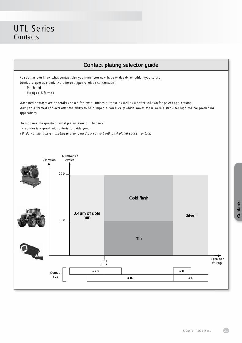
Contact plating selector guide
As soon as you know what contact size you need, you next have to decide on which type to use.
Souriau proposes mainly two different types of electrical contacts:
- Machined
- Stamped & formed
Machined contacts are generally chosen for low quantities purpose as well as a better solution for power applications.
Stamped & formed contacts offer the ability to be crimped automatically which makes them more suitable for high volume production
applications.
Then comes the question: What plating should I choose ?
Hereunder is a graph with criteria to guide you:
NB: do not mix different plating (e.g. tin plated pin contact with gold plated socket contact).
250
100
0.4µm of gold min
Gold fl ash
Silver
Tin
5mA5mV
Contact size
#20 #12
#16 #8
VibrationNumber of
cycles
Current / Voltage
Co
ntac
ts

22 © 2013 – SOURIAU
UTL SeriesContacts
Electrical characteristics:contact resistance
#16Ø1.6mm
Machined < 3m
Stamped & formed < 6m
Available platings (contact supply separately)
K Min 0.4µ gold over 2µ Ni
S31Active part: Gold fl ash over Ni
Crimp area: Nickel
S18
Active part: 0.75µ gold minover 2µ Ni
Crimp area: 1.3µ tin over NiOther: Nickel
TK6 2-5µ Sn pre-plated
Conscious of the wide variety of applications, contact packaging has been considered for small series (bulk packaging) and high volume production (reeled contacts):
Size contact #16
Contact supply separately
• 50 pieces bulk packing (machined contacts)
• 25 pieces loose packing (stamped & formed contacts)
• 1000 pieces bulk packing (machined contacts)
• 5000 pieces reeled (machined contacts)
• 3000 pieces reeled (stamped & formed contacts)
Contact selector guide
Packaging
23© 2013 – SOURIAU
UTL SeriesContacts
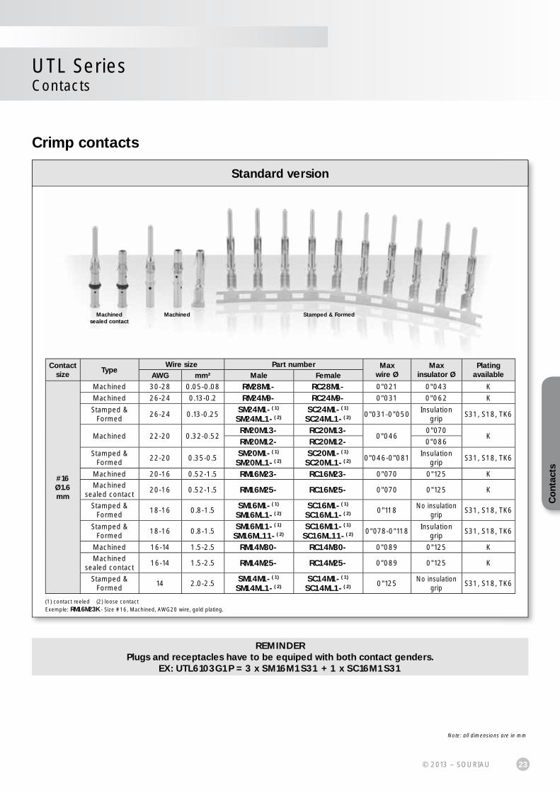
Crimp contacts
REMINDERPlugs and receptacles have to be equiped with both contact genders.
EX: UTL6103G1P = 3 x SM16M1S31 + 1 x SC16M1S31
(1) contact reeled (2) loose contactExemple: RM16M23K - Size #16, Machined, AWG20 wire, gold plating.
Standard version
Note: all dimensions are in mm
Contact size
TypeWire size Part number Max
wire ØMax
insulator ØPlating
availableAWG mm² Male Female
#16Ø1.6 mm
Machined 30-28 0.05-0.08 RM28M1- RC28M1- 0"021 0"043 K
Machined 26-24 0.13-0.2 RM24M9- RC24M9- 0"031 0"062 K
Stamped & Formed
26-24 0.13-0.25SM24M1-(1)
SM24ML1-(2)SC24M1-(1)
SC24ML1-(2) 0"031-0"050Insulation
gripS31, S18, TK6
Machined 22-20 0.32-0.52RM20M13- RC20M13-
0"0460"070
KRM20M12- RC20M12- 0"086
Stamped & Formed
22-20 0.35-0.5SM20M1-(1)
SM20ML1-(2)SC20M1-(1)
SC20ML1-(2) 0"046-0"081Insulation
gripS31, S18, TK6
Machined 20-16 0.52-1.5 RM16M23- RC16M23- 0"070 0"125 K
Machinedsealed contact
20-16 0.52-1.5 RM16M25- RC16M25- 0"070 0"125 K
Stamped & Formed
18-16 0.8-1.5SM16M1-(1)
SM16ML1-(2)SC16M1-(1)
SC16ML1-(2) 0"118No insulation
gripS31, S18, TK6
Stamped & Formed
18-16 0.8-1.5SM16M11-(1)
SM16ML11-(2)SC16M11-(1)
SC16ML11-(2) 0"078-0"118Insulation
gripS31, S18, TK6
Machined 16-14 1.5-2.5 RM14M30- RC14M30- 0"089 0"125 K
Machinedsealed contact
16-14 1.5-2.5 RM14M25- RC14M25- 0"089 0"125 K
Stamped & Formed
14 2.0-2.5SM14M1-(1)
SM14ML1-(2)SC14M1-(1)
SC14ML1-(2) 0"125No insulation
gripS31, S18, TK6
Machined Stamped & FormedMachinedsealed contact
Co
ntac
ts

24 © 2013 – SOURIAU
UTL SeriesContacts
#16 coaxial contacts
We provide 2 types of coaxial contacts suitable for 50 or 75, coaxial cable or twisted pair cable.
Monocrimp coaxial contact
• The monocrimp one-piece coaxial contacts offer high reliability plus the economic advantage of a 95% reduction in installation time over conventional assembly methods.
• This economy is achieved by simultaneously crimping both the inner conductor and outer braid or drain wire.
Multipiece crimp coaxial contact
• The inner conductor and outer braid is crimped individually.
• The thermoplastic insulating bushing in the outer body is designed to accept and permanently retain the inner contact.
• An outer ferrule is used to connect the braid to the outer contact and provide cable support to ensure against bending and vibration.
Suitable for Coaxial cable or Twisted cable
• For jacket diameter from 1.78 to 3.05mm Inner conductor up to 2.44mm diameter
• For jacket diameter from 0.64 to 1.45mm Inner conductor from AWG30 to AWG24
Contacts for coaxial cable summary
Contact typeContact range
Contact part number with cable combination
Cabling noticeMale contact Female contact
Multipiece RMDXK10D28 RCDXK1D28See page 50
See pages 54 & 55
Monocrimp RMDX60xxD28 RCDX60xxD28 See page 56
Contacts for twisted pairs cable summary
Contact typeContact range Contact part number with
cable combinationCabling notice
Male contact Female contact
MultipieceRMDXK10D28+ YORK090
RCDXK1D28+ YORK090 See page 51
See page 52
Monocrimp RMDX60xxD28 RCDX60xxD28 See page 53
Coaxial contact range
25© 2013 – SOURIAU
UTL SeriesContacts
Co
ntac
ts

UT
LS
erie
s
27© 2013 – SOURIAU
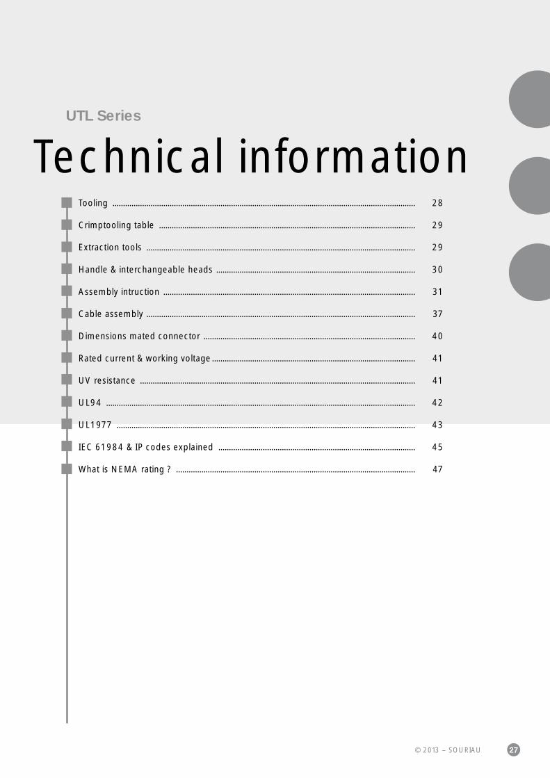
Technical informationUTL Series
Tooling ............................................................................................................................................... 28
Crimptooling table ......................................................................................................................... 29
Extraction tools ............................................................................................................................... 29
Handle & interchangeable heads .............................................................................................. 30
Assembly intruction ....................................................................................................................... 31
Cable assembly ............................................................................................................................... 37
Dimensions mated connector .................................................................................................... 40
Rated current & working voltage ................................................................................................ 41
UV resistance .................................................................................................................................. 41
UL94 .................................................................................................................................................. 42
UL1977 ............................................................................................................................................. 43
IEC 61984 & IP codes explained ............................................................................................. 45
What is NEMA rating ? ................................................................................................................. 47

28 © 2013 – SOURIAU
Souriau has been working in partnership with Mecal for a good number of years. With sales offi ces located in all major industrial regions of the world, the combined strengths of both organisations has resulted in a truly global solution to all your production tooling needs.
Mecal sales network:
Mecal is leader in manufacturing tooling forcrimping terminals over a stripped wire.Established in 1976, Mecal has become one of the world's leading companies dedicated to the design and manufacture of semi automatic production tools for strip fed, open barrel crimp terminals, serving the Automotive, Telecom and Datacomm industry.
The extreme environment interconnect specialist “from deep sea to deep space”.Souriau designs manufactures and markets high performance interconnect solutions for severeenvironments dedicated to the aerospace, defence, light and heavy industry markets.
Mini Applicator Stripper Presses
Tooling
www.mecal.net/eng/retevendita.php
Automatic crimping tools
UTL SeriesTechnical information
29© 2013 – SOURIAU
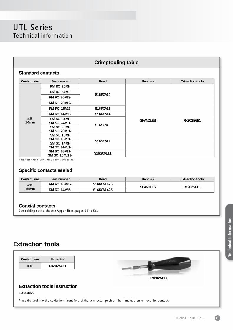
UTL SeriesTechnical information
Specifi c contacts sealed
Coaxial contactsSee cabling notice chapter Appendices, pages 52 to 56.
Standard contacts
Note: endurance of SHANDLES tool = 5 000 cycles.
Crimptooling table
Contact size Part number Head Handles Extraction tools
#161.6mm
RM/RC 28M1-
S16RCM20
SHANDLES RX2025GE1
RM/RC 24M9-
RM/RC 20M13-
RM/RC 20M12-
RM/RC 16M23- S16RCM16
RM/RC 14M30- S16RCM14SM/SC 24M1-SM/SC 24ML1- S16SCM20SM/SC 20M1-SM/SC 20ML1-SM/SC 16M1-SM/SC 16ML1- S16SCML1SM/SC 14M1-SM/SC 14ML1-SM/SC 16M11-SM/SC 16ML11- S16SCML11
Contact size Part number Head Handles Extraction tools
#161.6mm
RM/RC 16M25- S16RCM1625SHANDLES RX2025GE1
RM/RC 14M25- S16RCM1425
RX2025GE1
Contact size Extractor
#16 RX2025GE1
Extraction tools
Extraction tools instructionExtraction:
Place the tool into the cavity from front face of the connector, push on the handle, then remove the contact.
Tech
nica
l inf
orm
atio
n
30 © 2013 – SOURIAU
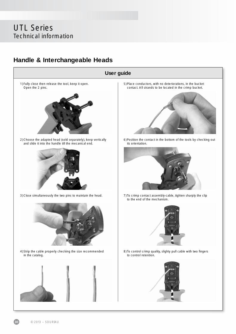
Handle & Interchangeable Heads
User guide
1) Fully close then release the tool, keep it open. Open the 2 pins.
2) Choose the adapted head (sold separately), keep vertically and slide it into the handle till the mecanical end.
3) Close simultaneously the two pins to maintain the head.
4) Strip the cable properly checking the size recommended in the catalog.
5) Place conductors, with no deteriorations, in the bucket contact. All strands to be located in the crimp bucket.
6) Position the contact in the bottom of the tools by checking out its orientation.
7) To crimp contact assembly-cable, tighten sharply the clip to the end of the mechanism.
8) To control crimp quality, slighty pull cable with two fi ngers to control retention.
UTL SeriesTechnical information

31© 2013 – SOURIAU
UTL SeriesTechnical information
Assembly instruction
Tech
nica
l inf
orm
atio
n
Part number Stripping length L
(mm)Male Female
Machined contact #16
RM28M1- / RM24M9-RM20M13- / RM20M12-
RC28M1- / RC24M9-RC20M13- / RC20M12- 4.8
RM16M23- / RM14M30- RC16M23- / RC14M30- 7.1
RM16M25K / RM14M25K RC16M25K / RC14M25K 5.4 / 5.2
Stamped & formed #16
SM24M1- / SM24ML1-SM20M1- / SM20ML1
SC24M1- / SC24ML1-SC20M1- / SC20ML1- 4
SM16M11- / SM16ML11- SC16M11- / SC16ML11- 4.6
SM16M1- / SM16ML1- SC16M1- / SC16ML1- 6.3
SM14M1- / SM14ML1- SC14M1- / SC14ML1- 6.3
L
L
Without insulation support
L
With insulation support
Wire stripping crimp version

32 © 2013 – SOURIAU
UTL SeriesTechnical information
Activecontact
partContact type
Dielocationon heads
Wiresectionrange
Section(mm²)
Tensilestraight
test (mini)
Height(Mm)
H (±0.075)
Width(Mm)
W (±0.075)Head's P/N
Machinedcontacts size 16
RM/RC 28M1K* 30/28AWG 30 0.05 min 11 N
1.14 1.41
S16RCM20
AWG 28 0.08 max 11 N
RM/RC 24M9K* 26/24AWG 26 0.12 min 15 N
1.15 1.41AWG 24 0.25 max 32 N
RM/RC 20M13K*22/20
AWG 22 0.32 min 40 N
1.26 1.76AWG 20 0.50 max 60 N
RM/RC 20M12K*AWG 22 0.32 min 40 NAWG 20 0.50 max 60 N
RM/RC 16M23K*20 AWG 20 0.50 max 60 N 1.66 2.18
S16RCM16 18 AWG 18 0.82 max 90 N 1.80 2.2816 AWG 16 1.50 max 150 N 1.96 2.43
RM/RC 14M25K16 AWG 16 1.50 min 150 N 2.10 2.68
S16RCM1425 14 AWG 14 2.50 min 230 N 2.30 2.78
RM/RC 16M25K18 AWG 18 0.82 max 90 N 1.80 2.28
S16RCM162516 AWG 16 1.50 max 150 N 1.96 2.43
RM/RC 14M30K*16 AWG 16 1.50 min 150 N 2.10 2.68
S16RCM1414 AWG 14 2.50 min 230 N 2.30 2.78
S & Fcontacts size 16
SM/SC 24ML1TK6* 26/24AWG 26 0.12 min 15 N
0.84 1.50S16SCM20
AWG 24 0.25 max 32 N
SM/SC 20ML1TK6* 22/20AWG 22 0.32 min 40 N
1.02 1.54AWG 20 0.50 max 60 N
SM/SC16ML11TK6*
18 AWG 18 0.82 min 90 N 1.32 2.09S16SCML11
16 AWG 16 1.50 max 150 N 1.36 2.10
SM/SC 16ML1TK6*18 AWG 18 0.82 min 90 N 1.49 2.02
S16SCML116 AWG 16 1.50 max 150 N 1.7 2.05SM/SC 14ML1TK6* 14 AWG 14 2.50 max 230 N 1.79 2.58
(1): example of plating, for other plating see page 22
W W
H HMachinedcontact
Stamped & Formedcontact
Crimping
One of the key factors which affects the performance of a connec-tor, is the way contacts are terminated. Crimped connections are nowadays seen as the best solution to ensure quality throughout the lifetime of the product. Here are some reasons why we recommend this method of termination for UTS connectors:
Advantages (Extract from the IEC 60352-2):- Effi cient processing of connections at each production level- Processing by fully-automatic or semi- automatic crimping machines, or with hand operated tools- No cold-soldered joints- No degradation of the spring characteristic of female contacts by the soldering temperature
- No health risk from heavy metal and fl ux steam- Preservation of conductor fl exibility behind the crimped connection- No burnt, discolored and overheated wire insulation- Good connections with reproducible electrical and mechanical performances- Easy production control.
To ensure that the crimp tooling is performing according tooriginal specifi cations, it is important to carry out regular checks. A com-mon way to check the performance of tooling is with a simple pull test, ideally using a dedicated electric pull tester. Minimum recom-mended full forces are indicated in the tables below:

33© 2013 – SOURIAU
• 1 - Female insulator: Strip external cable sheath, adjust ground cable length• 2 - Male insulator: Strip external cable sheath, adjust signal cable lengths• 3 - Crimp contacts• 4 - Place the lubrifi cant on the contact orings• 5 - Place all the contacts inside the corresponding cavities in the same time• 6 - Manually push each contact, or use specifi c tools, until audible click. Check each contact rétention, with a traction with two fi ngers
UTL stripping dimensions
* see page 31
UTL0103G1P - UTL6103G1P - UTL7103G1P - UTL1103G1P
UTL0103G1S - UTL6103G1S -UTL7103G1S - UTL1103G1S
Ground contact must be different compared to the others.
L*
L*
30.1mm32.1mm
Phase lines - male contacts Phase lines - male contacts
Ground line - female contact
Ground line - female contact25mm
25mm
Assembly instruction
UTL SeriesTechnical information
• Strip wires, crimp contacts• Insert contacts into connector cavities (insert manually or use tool RTM205 crimp contacts)• Place receptacle in the panel cut-out (see dimension page 15)• Secure receptacle with M3 screws (not supplied), torque 0.7 N.m maxi
Panel
Panel
Receptacle fl ange
Pa
Pa
UTL 0 assembly (mounting suggestion)
Tech
nica
l inf
orm
atio
n
34 © 2013 – SOURIAU
UTL SeriesTechnical information
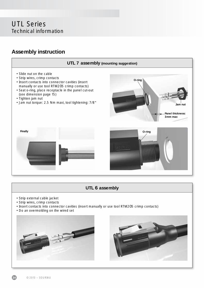
• Strip external cable jacket• Strip wires, crimp contacts• Insert contacts into connector cavities (insert manually or use tool RTM205 crimp contacts)• Do an overmolding on the wired set
UTL 6 assembly
• Slide nut on the cable• Strip wires, crimp contacts• Insert contacts into connector cavities (insert manually or use tool RTM205 crimp contacts)• Seat o-ring, place receptacle in the panel cut-out (see dimension page 15)• Tighten jam nut• Jam nut torque: 2.5 Nm maxi, tool tightening: 7/8"
O-ring
O-ringFinally
Jam nut
Panel thickness: 3mm max
UTL 7 assembly (mounting suggestion)
Assembly instruction

35© 2013 – SOURIAU
UTL SeriesTechnical information
Evaluation kit
The boot is semi-fl exible and heat-shrinkable with a moldable adhesive inner lining.
• 1 - Place the heat shrink boot over the cable • 2 - Strip the cable jacket (see page 33)• 3 - Strip the individual wires (see page 31)• 4 - Crimp the contacts• 5 - Place the contacts in their cavities, checking the retention by slightly pulling the cable• 6 - Clean the connector surface and the cable jacket with isopropyl alcohol (Nota: It is advised to rub the jacket with sand paper and clean the jacket before shrinking the boot)• 7 - Position the boot over the rear threads• 8 - Heat the boot with a heat gun: minimum shrink temp: 80°C - minimum full recovery temp: 110°C make sure to apply the heat evenly around the boot. Starting by applying the heat from the rear of the connector. Do not apply excessive heat, as it will damage the connector and/or boot.• 9 - Let the boot cool down• 10 - Check for good retention and the boot glue grip.
4 8
5 9
7 10
Tech
nica
l inf
orm
atio
n

36 © 2013 – SOURIAU
UTL0
Male Female
15.8 mini 7 mini
8.8 mini 12 mini
UTL7
Male Female
17.8 mini 9 mini
10.7 mini 14 mini
UTL6
Male Female
16 mini 7.4 mini
9 mini 12.4 mini
UTL SeriesTechnical information
SWS mounting
Push the sealing plug into each connector cavity to seal until a mechanical stop.
Note: all dimensions are in mm
Assembly instruction
37© 2013 – SOURIAU
UTL SeriesTechnical information
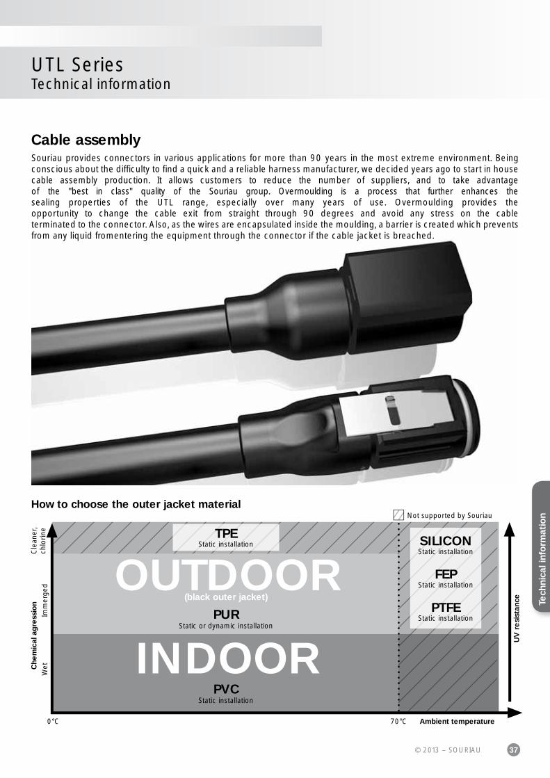
Cable assemblySouriau provides connectors in various applications for more than 90 years in the most extreme environment. Being conscious about the diffi culty to fi nd a quick and a reliable harness manufacturer, we decided years ago to start in housecable assembly production. It allows customers to reduce the number of suppliers, and to take advantage of the "best in class" quality of the Souriau group. Overmoulding is a process that further enhances the sealing properties of the UTL range, especially over many years of use. Overmoulding provides the opportunity to change the cable exit from straight through 90 degrees and avoid any stress on the cableterminated to the connector. Also, as the wires are encapsulated inside the moulding, a barrier is created which prevents from any liquid fromentering the equipment through the connector if the cable jacket is breached.
OUTDOOR
INDOOR
UV
re
sist
ance
Ambient temperature70°C0°C
PVCStatic installation
PURStatic or dynamic installation
Wet
Cle
aner
,ch
lorin
eIm
mer
ged
Che
mic
al a
gre
ssio
n
(black outer jacket)
Not supported by Souriau
TPEStatic installation SILICON
Static installation
FEPStatic installation
PTFEStatic installation
How to choose the outer jacket material
Tech
nica
l inf
orm
atio
n

38 © 2013 – SOURIAU
UTL SeriesTechnical information
Overmolding description
Discrete connector
Overmoulded connector
Compound
O ringPVC or PURovermolding
...water ingress unhampered, leading to damage.
...prevents water ingress via capillary action.
If cable jacket is breached...
If cable jacket is breached...
39© 2013 – SOURIAU
UTL SeriesTechnical information
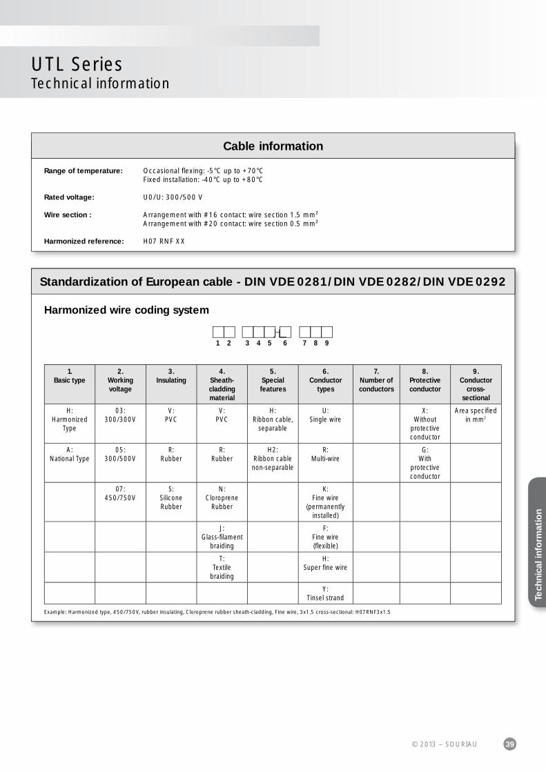
Standardization of European cable - DIN VDE 0281/DIN VDE 0282/DIN VDE 0292
1.Basic type
2.Working voltage
3.Insulating
4.Sheath-cladding material
5.Special features
6.Conductor
types
7.Number of conductors
8.Protective conductor
9.Conductor
cross-sectional
H:Harmonized
Type
03:300/300V
V:PVC
V:PVC
H:Ribbon cable,
separable
U:Single wire
X:Without
protective conductor
Area specifi ed in mm2
A:National Type
05:300/500V
R:Rubber
R:Rubber
H2:Ribbon cablenon-separable
R:Multi-wire
G:With
protective conductor
07:450/750V
S:Silicone Rubber
N:Cloroprene
Rubber
K:Fine wire
(permanently installed)
J:Glass-fi lament
braiding
F:Fine wire (fl exible)
T:Textile
braiding
H:Super fi ne wire
Y:Tinsel strand
1 32 4 5 6 7 8 9
Harmonized wire coding system
Example: Harmonized type, 450/750V, rubber insulating, Cloroprene rubber sheath-cladding, Fine wire, 3x1.5 cross-sectional: H07RNF3x1.5
Cable information
Range of temperature: Occasional fl exing: -5°C up to +70°C Fixed installation: -40°C up to +80°C
Rated voltage: U0/U: 300/500 V
Wire section : Arrangement with #16 contact: wire section 1.5 mm² Arrangement with #20 contact: wire section 0.5 mm²
Harmonized reference: H07 RNF XX
Tech
nica
l inf
orm
atio
n
40 © 2013 – SOURIAU
UTL SeriesTechnical information
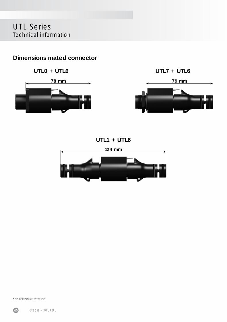
Dimensions mated connector
78 mm
UTL0 + UTL6
124 mm
UTL1 + UTL6
79 mm
UTL7 + UTL6
Note: all dimensions are in mm

41© 2013 – SOURIAU
UTL SeriesTechnical information
Rated current & working voltage
The current carrying capacity of a connector is limited by the thermal properties of materials used in it's construction. The amount of current that can be handled depends on the size of cable used, the ambient temperature and the heat that is generated inside the connector. Part 3 of the IEC 60512 standard determines through a derating curve, the maximum current permissible. Wire size plays an important role since they help to dissipate heat and avoid overheating (Fig 1 and Fig 2).
Please note that the curve should be adjusted when dealing with potential hot spots, which can occur as a result of unequal loading of current across a number of contacts. As a general rule, it is best to avoid locating power handling contacts in the middle of the connector; try to locate them towards the edge where heat can be dissipated more effectively. Eventually you should fi nd a level which represents the permissible operating range:
The rated current is defi ned as uninterrupted continuous current that a connector can take when all contacts are energized simultaneously without exceeding the maximum limit of temperature. The earth contact is never loaded.
0 20 40 60 80 100 1200
3
5
8
10
13
15
18
20
23
25
28
30
Cur
rent
(A)
Ambient Operating Temperature (°C)
Fig.1: UTL – 1.5mm² wires
0 20 40 60 80 100 1200
3
5
8
10
1518
2325
28
30
3335
Cur
rent
(A)
Ambient Operating Temperature (°C)
Fig.2: UTL – 2.5mm² wires
Current use Limited use Not recommended use
Current carrying capacity
Solar radiation affects all materials, but plastics can be susceptible to extreme degradation over time. The choice of materials for the UTL series was therefore a critical consideration.
All over the world we are not exposed to the same amount of energy given by the sun. The chart shown here clearly illustrates this.
So Souriau has chosen a polymeric material able to wit-hstand sunlight over a long period of time. For that we carefully followed the UL 746C and fi nally picked up a "f1" material. As a consequence our connector has been approved for outdoor use.
Yearly mean of daily irradiation in UV (280-400 nm)on horizontal plane (J/cm²) (1990-2004)
90°
60°
30°
0°
- 30°
- 90°
- 60°
90°60°30°0°- 30°- 90° - 60° 180°150°120°- 180° - 150° - 120°
J/cm²
0 10
20
30
50
60
70
80
90
10
0
110
120
130
150
16
0
170
18
0
19
0
40
140
UV resistance
20
13
Tech
nica
l inf
orm
atio
n

42 © 2013 – SOURIAU
UTL SeriesTechnical information
There are two main standards for industrial connectors: UL94 & UL1977
UL 94: Tests for Flammability of Plastic Materials for Partsin Devices and AppliancesThis standard is dedicated to plastics fl ammability. It characterises how the material burns in various orientation and thicknesses. Whereasmost of our competitor are using a 50W test to classifi ed the ability of their solution to withstand fi re, Souriau decided to increase this to a500W test. New regulations tend to emphasize the importance of burning behavior making the 50W test less and less relevant.
The UTL series has been rated at 5VA.
Procedure: Bar specimens are to be 125±5 mm long by 13±0.5 mm wide, and provided in the minimum thickness.Plaque specimens are to be 150±5 mm by 150±5 mm and provided in the minimum thickness.Thicker specimens may also be provided and shall be tested if the results obtained on the minimum thickness indicate inconsistent test results. The maximum thickness is not to exceed 13 mm.
5VA Vertical burning:• The specimen is clamped from the upper 6 mm of the specimen, with the longitudinal axis vertical, so that the lower end of the specimen is 300±10 mm above a horizontal layer of not more than 0.08 g of absorbent cotton thinned to approximately 50 x 50 mm and a maximum thickness of 6 mm. • The 500W fl ame is then to be applied to one of the lower corners of the specimen so that the tip of the blue cone is within 0 to 3 mm of the specimen edge.• Apply the fl ame for 5±0.5 seconds and then remove for 5±0.5 seconds. Repeat the operation until the specimen has been subjected to fi ve applications of the test fl ame.
Underwriter Laboratories
5VA Horizontal burning:• Support the plaque specimen by a clamp in the horizontal plane.• The fl ame is then to be applied to the centre of the bottom surface of the plaque so that the tip of the blue cone is within 0 to 3 mm of the plaque surface.• Apply the fl ame for 5±0.5 seconds and then remove for 5±0.5 seconds. Repeat the operation until the plaque specimen has been subjected to fi ve applications of the test fl ame.• After the fi fth application of the test fl ame, and after all fl aming or glowing combustion has ceased, it is to be observed whether or not the fl ame penetrated (burned through) the plaque material. In addition, no opening greater than 3 mm shall appear after the test.
Conditions 94-5VA
Afterfl ame time plus afterglow time after fi fth fl ame application for each individual bar specimen
60s
Cotton indicator ignited by fl aming particles or drops from any bar specimen
No
Burn-through (hole) of any plaque specimen No
300±10 mm
125±10 mm
13±0.5 mm
45°
CottonCotton
MaterialMaterial
Overall height of fl ameInner blue
cone
13±
0.5 m
m
MaterialMaterial
150±0.5 mm
Center
45°

43© 2013 – SOURIAU
UTL SeriesTechnical information
Underwriter Laboratories
UL1977There are several standards which deal with plug and receptacle. Each of them is only for a small area of applications. It could betelecommunication, Etc. The UL 1977 covers single and multipole connectors intended for factory assembly.
Requirements apply to devices in taking into account intensity and voltage. There a categories as follows:
Type 0 Type 1A
Tybe 1B
Type 2
Type 3
Type 4
0
0
8.3 A
31 A
200 A
1000 A
600 V30 V
(42 V peak)
According to above table, the level of performance that has to be reached could be different. Most of them are explained in the following page.
Assembly:Connector has to be keyed to prevent any mismating that can damage the machine or hurt the user. In the same way, plugs and sockets have to be equipped to protect persons against contact with live parts.Finally the identifi ed grounding contact shall be located so that the corresponding electrical continuity has to be completed before any other contact.
Insulating materials:Material uses for electrical insulation, as a minimum, have to comply with the characteristics shown below:
• Minimum ratings for polymeric materials
Type Flame ratingRelative thermal index (RTI)
Electrical/mechanical w/o impact */**
0 - 50/50
1A HB 50/50
1B HB 50/50
2 HB 50/50
3 HB 50/50
4 HB 50/50
* The RTI of the material shall not be lower than the temperature measured during the Temperature Test.** For a thickness less than that for which a value has been established, the RTI of the minimum thickness with an established value shall be used.
Tech
nica
l inf
orm
atio
n

44 © 2013 – SOURIAU
UTL SeriesTechnical information
Underwriter Laboratories
UL1977
Spacing:For a 250V max connector, distance through air or over material shall be 1.2mm whereas from 250V to 600V connector the spacing is 3.2 minimum. These distances have to be taken between uninsulated live parts as shown in the matrix below:
An alternative way to determine voltage rating is with the Dielectric-Withstand test. If during one minute there is no arc-over or breakdown the rated voltage is given as given below:
a) 500 volts for a type 1B device b) 1000 volts plus twice rated voltage for types 1A, 2, 3 and 4 devices.
• Applicability of spacing requirements
TypeUninsulated live part - uninsulated
live part of opposite polarityUninsulated live part - uninsulated
grounded metal partUninsulated live part - exposed
dead metal part
0 No No No
1A Yes Yes Yes
1B Yes Yes No
2 Yes Yes Yes
3 Yes Yes Yes
4 Yes Yes Yes
Marking:A device shall be legibly marked with the manufacturer's trade name, trade mark, or other descriptive marking by which the organisation responsible for the product may be identifi ed. (Exception: If the device is too small, or where the legibility would be diffi cult to attain, the manufacturer’s name, trademark, or other descriptive marking may appear on the smallest unit container or carton)
The following shall be marked on the device or on the smallest unit container or carton or on a stuffer sheet in the smallest unit container or carton:
a) The catalogue number or an equivalent designation b) The electrical rating in both volts and amperes, if assigned c) Whether ac or dc, if restricted d) Flammability class, if identifi ed
Example - Marking for the arrangement 10-3: 500V 10A UL94 V-0

45© 2013 – SOURIAU
UTL SeriesTechnical information
The norm is dedicated to connectors with rated voltage above 50V and up to 1000V and rated currents up to 125A per contact. Butdepending of your application connectors should be compliant with another standard. This has to be double checked with the customer.
There are lot of constructional requirements and performances specifi ed in that standard. Most of them are illustrated in greater details hereafter.
Provisions for earthing: The UTL connector is intended to be used on Class II systems. Even if the purpose of our connector is not to interrupt current, we oftensee a need to add a protective earth contact. Then this one shall be a “First mate, last break” style. Critically, among all of the normalassumptions we make in designing a connector, this contact has to be considered as a live part and must be protected against electric shock by double or reinforced insulation.
IP Code:IP is a coding system defi ned by the IEC 60529 to indicate thedegrees of protection provided by an enclosure. The aim of this is to give information regarding the accessibility of live parts against ingress of water and other foreign bodies.
1st digit Degree of protection 2nd digit Degree of protection0 No protection against accidental contact.
No protection against solid foreign bodies.0 No protection against water.
1 Protection against contacts with any large area by hand and against large solid foreign bodies with a diameter bigger than 50 mm.
1 Drip-proof.Protection against vertical water drips.
2 Protection against contacts with the fi ngers.Protection against solid foreign bodies with a diameter bigger than 12 mm.
2 Drip-proof.Protection against water drips up to a 15° angle.
3 Protection against tools, wires or similar objects with a diameter bigger than 2.5 mm.Protection against small solid bodies with a diameter bigger than 2.5 mm.
3 Spray-proof.Protection against diagonal water drips up to a 60° angle.
4 As 3 however diameter is bigger than 1 mm. 4 Splash-proof.Protection against splashed water from all directions.
5 Full protection against contacts. Protection against interior inju-rious dust deposits.
5 Hose-proof.Protection against water (out of a nozzle) from all directions.
6 Total protection against contacts.Protection against penetration of dust.
6 Protection against temporary fl ooding.
7 Protection against temporary immersions.8 Protection against water pressure.
Pressure to be specifi ed by supplier.
9K High pressure hose-proof.Protection against high pressure water (out of a nozzle) from all directions.
IP 6 8
First digit(foreign bodies
protection)
Second digit(water
protection)
Code letters(internationalProtection)
UTL offers high sealing performance IP68 / 69K… Even in dynamic situations.
In addition to the IEC 60529 we conjointly use the DIN 40050 part 9 which are dedicated to road vehicles. The main differences are:
• First digit: 5 replaced by 5K, 6 by 6K. In the DIN the tested equipment is not depressurized as it is in the IEC.• Second digit: 5K and 6K has been added and are equivalent respectively to 5 and 6 but with higher pressure. 9K which represents the High pressure cleaning.
IEC 61984 ed.2.0 “Copyright © 2008 IEC Geneva, Switzerland.www.iec.ch"IEC 60664-1 ed.2.0 “Copyright © 2007 IEC Geneva, Switzerland.www.iec.ch”
IEC 61984
Tech
nica
l inf
orm
atio
nTTe
hchinica
ll iinff
orm
atiio
nTe
chni
cal i
nfo
rmat
ion
46 © 2013 – SOURIAU
UTL SeriesTechnical information
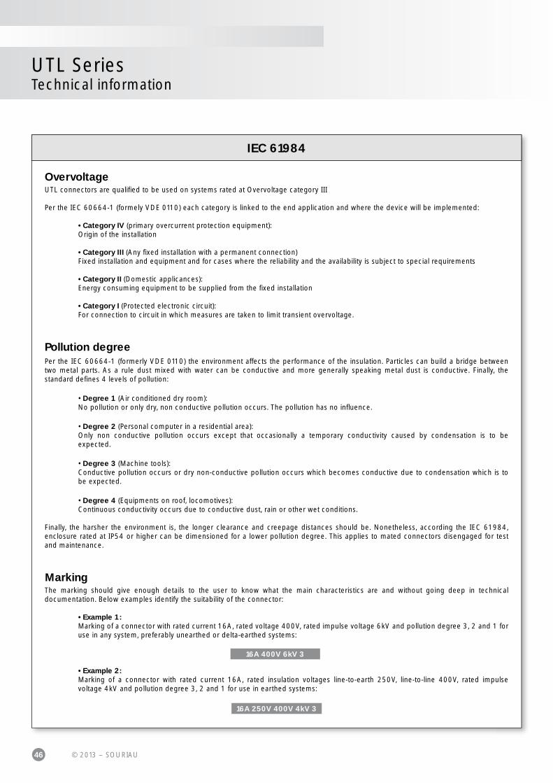
OvervoltageUTL connectors are qualifi ed to be used on systems rated at Overvoltage category III
Per the IEC 60664-1 (formely VDE 0110) each category is linked to the end application and where the device will be implemented: • Category IV (primary overcurrent protection equipment): Origin of the installation • Category III (Any fi xed installation with a permanent connection) Fixed installation and equipment and for cases where the reliability and the availability is subject to special requirements • Category II (Domestic applicances): Energy consuming equipment to be supplied from the fi xed installation • Category I (Protected electronic circuit): For connection to circuit in which measures are taken to limit transient overvoltage.
Pollution degreePer the IEC 60664-1 (formerly VDE 0110) the environment affects the performance of the insulation. Particles can build a bridge between two metal parts. As a rule dust mixed with water can be conductive and more generally speaking metal dust is conductive. Finally, thestandard defi nes 4 levels of pollution:
• Degree 1 (Air conditioned dry room): No pollution or only dry, non conductive pollution occurs. The pollution has no infl uence.
• Degree 2 (Personal computer in a residential area): Only non conductive pollution occurs except that occasionally a temporary conductivity caused by condensation is to be expected.
• Degree 3 (Machine tools): Conductive pollution occurs or dry non-conductive pollution occurs which becomes conductive due to condensation which is to be expected.
• Degree 4 (Equipments on roof, locomotives): Continuous conductivity occurs due to conductive dust, rain or other wet conditions.
Finally, the harsher the environment is, the longer clearance and creepage distances should be. Nonetheless, according the IEC 61984,enclosure rated at IP54 or higher can be dimensioned for a lower pollution degree. This applies to mated connectors disengaged for test and maintenance.
MarkingThe marking should give enough details to the user to know what the main characteristics are and without going deep in technicaldocumentation. Below examples identify the suitability of the connector:
• Example 1: Marking of a connector with rated current 16A, rated voltage 400V, rated impulse voltage 6kV and pollution degree 3, 2 and 1 for use in any system, preferably unearthed or delta-earthed systems:
16A 400V 6kV 3
• Example 2: Marking of a connector with rated current 16A, rated insulation voltages line-to-earth 250V, line-to-line 400V, rated impulse voltage 4kV and pollution degree 3, 2 and 1 for use in earthed systems:
16A 250V 400V 4kV 316A 250V 400V 4kV 3
16A 400V 6kV 3
IEC 61984
47© 2013 – SOURIAU
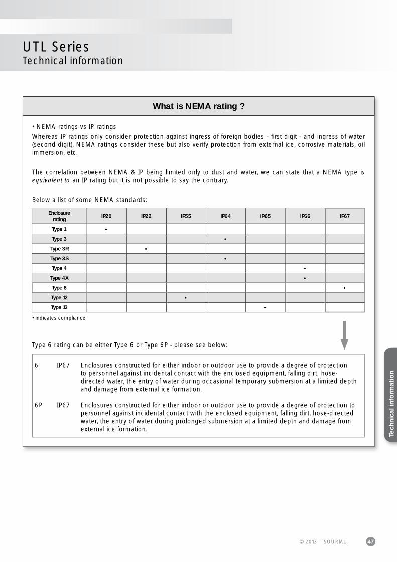
UTL SeriesTechnical information
Enclosurerating
IP20 IP22 IP55 IP64 IP65 IP66 IP67
Type 1 •
Type 3 •
Type 3R •
Type 3S •
Type 4 •
Type 4X •
Type 6 •
Type 12 •
Type 13 •
• indicates compliance
6 IP67 Enclosures constructed for either indoor or outdoor use to provide a degree of protection to personnel against incidental contact with the enclosed equipment, falling dirt, hose- directed water, the entry of water during occasional temporary submersion at a limited depth and damage from external ice formation.
6P IP67 Enclosures constructed for either indoor or outdoor use to provide a degree of protection to personnel against incidental contact with the enclosed equipment, falling dirt, hose-directed water, the entry of water during prolonged submersion at a limited depth and damage from external ice formation.
Type 6 rating can be either Type 6 or Type 6P - please see below:
• NEMA ratings vs IP ratings
Whereas IP ratings only consider protection against ingress of foreign bodies - first digit - and ingress of water (second digit), NEMA ratings consider these but also verify protection from external ice, corrosive materials, oil immersion, etc.
The correlation between NEMA & IP being limited only to dust and water, we can state that a NEMA type is equivalent to an IP rating but it is not possible to say the contrary.
Below a list of some NEMA standards:
What is NEMA rating ?
Tech
nica
l inf
orm
atio
n

UT
LS
erie
s
49© 2013 – SOURIAU
AppendicesUTL Series
#16 coaxial contacts - cabling notices ................................................................................... 50
Glossary of terms ........................................................................................................................... 57
Part number Index ......................................................................................................................... 58

50 © 2013 – SOURIAU
UTL SeriesAppendices
#16 coaxial contacts
Cabletype
Impe-dance
Contact type
Ø overjacket
Ø overdielectric
Inner cond size
Ø outer braid Male contact kit for coaxial
cable
Female contact kit for coaxial
cableinch mm inch mm
Ext. Ø mm
inch mm
RG161/U 75
Multipiece
0.09 2.29 0.057 1.45
RMDXK10D28 RCDXK1D28
RG179A/U 75 0.105 2.67 0.063 1.6 0.3 0.084 2.13 max
RG179B/U 75 0.105 2.67 0.063 1.6 0.3 0.084 2.13 max
RG187/U 75 0.11 2.79 max 0.06 1.52 0.3
RG188/U 50 0.11 2.79 max 0.06 1.52 0.51 0.078 1.98 max
RG174/U 50 0.11 2.92 0.06 1.52 0.48 0.088 2.24 max
AMPHENOL 21-598 50 0.105 2.67 0.06 1.52 0.48
RG196/U 50 0.08 2.03 max 0.034 0.086 0.3
RG178A/U 50 0.075 1.91 0.034 0.86 0.3 0.054 1.37 max
RG/188A/U 50
Monocrimp
0.110 2.79 0.06 1.52 0.51 0.078 1.98 max RMDX6036D28 RCDX6036D28
KX21TVT (europe)RG178 B/U
50 0.075 1.91 0.034 0.86 0.3 0.054 1.37 max RMDX6034D28 RCDX6034D28
RG178 / BU 50 0.075 1.91 0.034 0.86 0.3 0.054 1.37 max RMDX6050D28 RCDX6016D28
RG174/U 50 0.115 2.92 0.06 1.52 0.48 0.088 2.24 max RMDX6032D28 RCDX6032D28
RG188A/U 50 0.11 2.79 0.06 1.52 0.51 0.078 1.98 max RMDX6036D28 RCDX6036D28
RG316/U 50 0.107 2.72 0.6 1.52 0.51 0.078 2.05 max RMDX6036D28 RCDX6036D28
raychem 5024A3111 50 0.12 3.05 0.083 2.11 0.64 0.097 2.46 RMDX6052D28 RCDX6052D28
raychem 5026e1614 50 0.083 2.11 0.05 1.27 0.48 0.067 1.7 RMDX6036D28 RCDX6036D28
surprenant pn 8134 -Multipiece
0.1 2.54 0.058 1.47 0.3 RMDXK10D28 RCDXK1D28
PRD PN 247AS-C1123-001
-
Monocrimp
0.103 2.62 0.06 1.52 0.51 0.078 1.98 RMDX6018D28 RCDX6018D28
PRD PN 247AS-C1251 - 0.092 2.34 0.05 1.27 0.64 0.067 1.7 RMDX6018D28 RCDX6018D28
JUDD C15013010902 - 0.087 2.13 0.05 1.27 0.48 0.066 1.67 RMDX6036D28 RCDX6036D28
CDC PIN22939200 - 0.09 2.29 0.048 1.22 0.3 0.064 1.63 RMDX6046D28 RCDX6016D28
CDC PIN22939200 - 0.09 2.29 0.048 1.22 0.3 0.064 1.63 RMDX6050D28 RCDX6016D28
CDC PIN245670000 - 0.104 2.64 0.067 1.7 0.3 0.083 2.11 RMDX6050D28 RCDX6016D28
ampex - 0.114 2.9 0.075 1.91 0.38 0.09 1.29 RMDX6032D28 RCDX6032D28
TI PN 920580 - 0.7 1.78 0.038 0.96 0.48 0.054 1.37 RMDX6024D28 RCDX6024D28
Honeywell PN 58000062
- 0.12 3.05 0.077 1.960.41 solid
0.096 2.44 RMDX6026D28 RCDX6026D28
- - 0.104 2.64 0.067 1.7 0.3 2.11 RMDX6050D28 -
- - 0.09 2.29 0.048 1.22 0.3 1.63 RMDX6050D28 -
- - 0.114 2.9 0.075 1.91 0.38 1.29 RMDX6032D28 RCDX6032D28
- - 0.07 1.78 0.038 0.96 0.48 1.37 RMDX6024D28 RCDX6024D28
- - 0.12 3.05 0.077 1.96 0.41 2.44 RMDX6026D28 RCDX6026D28
Coaxial cable - Contact monocrimp and multipiece

51© 2013 – SOURIAU
UTL SeriesAppendices
Cabletype
Contact type
Inner AWG cond
Ø overjacket
(single wire)Inner cond size
Ø outerbraid Male
contact kit for coaxial cable
Femalecontact kit for coaxial cable
inch mmStranded defi nition
Ext. Ø mm
inch mm
2#24 stranded mil w 16878 type B
Multipiece
24 0.0491.24 max
7/.008 - - RMDXK10D28 RCDXK1D28
2 #24 solid mil-w-76 type LW 24 0.0471.12 max
1/.0201 - - RMDXK10D28 RCDXK1D28
2 #26 stranded mil w 76 type LWor mil w16878 type b&e
26 0.0431.09 max
7/.0063 0.16 - - RMDXK10D28 RCDXK1D28
2 #28 solid mil-w-81822/3 28 0.0280.71 max
- - RMDXK10D28 RCDXK1D28
TWISTED PAIR 1/.201 SOLID MIL w 76 TYPE lw or MIL W 16878
26 0.0441.12 max
1/.0201 0.511 - - RMDXK10D28 RCDXK1D28
twisted pair solid mil w 81822/3 28 0.0280.71 max
1/.0126 0.32 - - RMDXK10D28 RCDXK1D28
#28 7/.0036 per Hitachi specec-711 (13-2820)
Monocrimp
- 0.046 1.17 7/.0036 - - -RMDX6031D28 + YORX090
RCDX6031D28 + YORX090
20218201 - 0.028 0.71 - - - -RMDX6031D28 + YORX090
RCDX6031D28 + YORX090
#30 solid - 0.025 0.64 - - - -RMDX6015D28 + YORX090
RCDX6015D28 + YORX090
#26 7/.0063 26 0.028 0.71 7/.063 0.16 - -RMDX6031D28 + YORX090
RCDX6031D28 + YORX090
#26 19/.004 26 0.049 1.24 19/.004 - - -RMDX6019D28 + YORX090
RCDX6019D28 + YORX090
#24 7/.008 24 0.049 1.24 7/.008 - - -RMDX6019D28 + YORX090
RCDX6019D28 + YORX090
#24 19/.005 24 0.057 1.45 19/.005 - - -RMDX6019D28 + YORX090
RCDX6019D28 + YORX090
- 26 - 1.25 - - - 19x0.1RMDX6019D28 + YORX090
RCDX6019D28 + YORX090
- 24 - 1.25 - - - 7x0.2RMDX6019D28 + YORX090
RCDX6019D28 + YORX090
- 24 - 1.45 - - - 19x0.13RMDX6019D28 + YORX090
RCDX6019D28 + YORX090
- 26 - 0.7 - - - 7x0.16RMDX6031D28 + YORX090
RCDX6031D28 + YORX090
Twisted cable - Contact monocrimp and multipiece
Ap
pe
ndic
es

52 © 2013 – SOURIAU
Twisted pair cable multipiece contact cabling
UTL SeriesAppendices
#16 coaxial contacts
Cablereference
Contact type
Male contact
Female contact
Crimp tool
Die set
Stop bushing
Cable strip length
Inner conduc-tor crimp
Braid crimp
A B C g dim t dim g dim t dim2#24 stranded mil
w 16878 type B
Multipiece RMDXK10D28 RCDXK1D28 M10S1J - - See assembly notice
2 #24 solid mil-w-76 type LW
2 #26 strandedmil w 76 type LW or
mil w16878 type B & E
2 #28 solidmil-w-81822/3
twisted pair 1/.201 solid mil w 76 type LW
or mil w 16878
twisted pair solid mil w 81822/3
Male contact
Outer male contact
RMDX60-2Inner socketRFD26L-1
Outer hyringYOC074
Inner supporting sleeveRMDXB-055-3
Twisted pair adapterYORK-090
Conductor "Y"
Conductor "Z"
Strip lengths of cable
7.95±0.41
15.54±0.41
7.95±0.41
Outer hyringInner supporting sleeve
Twisted pair adapterLocking louver typical
Grounding louver typical
Step 1: Step 2: Step 3:
7.54
0.25±0.05
5.94±0.41
7.54±0.41
15.54±0.41
7.95±0.41When using solid wire fl atten conductor "X" and "Z" using N24FL-1 die as shown
Female contact
Step 1: Step 2: Step 3:
Outer hyringSupporting sleeve
Twisted pair adapter
Conductor "W"
Conductor "X"
Strip lengths of cable
6.35±0.41
13.49±0.41
7.95±0.41
Outer female contactRCDX60-2
Inner pinRMD26L-1
Outer hyringYOC074
Inner supporting sleeveRCDXB-055-1
Twisted pair adapterYORK-090
Note: all dimensions are in mm
53© 2013 – SOURIAU
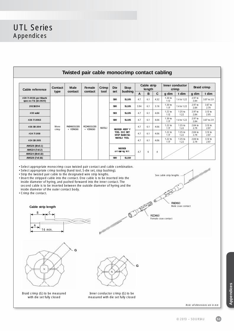
Twisted pair cable monocrimp contact cabling
UTL SeriesAppendices
Cable referenceContact
typeMale
contactFemale contact
Crimp tool
Die set
Stop bushing
Cable strip length
Inner conductor crimp
Braid crimp
A B C g dim t dim g dim t dim#28 7/.0036 per Hitachi spec ec-711 (13-2820)
Monocrimp
RMDX6031D28+ YORX090
RCDX6031D28+ YORX090
M10S1J
S80 SL105 4.7 6.1 4.321.30 to
1.121.4 to 1.22
2.97 to 2.84
3.07 to 2.9
20218204 S80 SL105 3.94 6.1 3.161.30 to
1.171.4 to 1.22
2.97 to 2.84
3.07 to 2.79
#30 solid S83 SL105 4.7 6.1 4.061.22 to
1.121.35 to 1.22
2.97 to 2.84
3.12 to 2.95
#26 7/.0063 S80 SL105 4.7 6.1 4.061.30 to
1.171.4 to 1.22
2.97 to 2.84
3.07 to 2.9
#26 19/.004M10SG8 ASSY'YTOOL DIE SETSTOP BUSHINGM10S1J TOOL
4.7 6.1 4.061.22 to
1.171.35 to 1.22
2.84 to 2.79
3.12 to 2.97
#24 7/.008 4.7 6.1 4.061.22 to
1.171.35 to 1.22
2.84 to 2.79
3.12 to 2.97
#24 19/.005 4.7 6.1 4.061.22 to
1.171.35 to 1.22
2.84 to 2.79
3.12 to 2.97
AWG26 (19x0.1)M10SG8
crimping kit 4.7 6 4AWG24 (7x0.2)
AWG24 (19x0.13)
AWG26 (7x0.16) S80 SL150
G
G
Braid crimp (G) to be measured with die set fully closed
Inner conductor crimp (G) to be measured with die set fully closed
RCDX60Female coax contact
RMDX60Male coax contact
See cable strip lengths
Cable strip length
A
B C
16 min.
• Select appropriate monocrimp coax twisted pair contact and cable combination.• Select appropriate crimp tooling (hand tool, S-die set, stop bushing).• Strip the twisted pair cable to the designated wire strip lengths.• Insert the stripped cable into the contact. One cable is to be inserted into the inside diameter of hyring, and pushed forwaerd into the inner contact. The second cable is to be inserted between the outside diameter of hyring and the inside diameter of the outer contact body.• Crimp the contact.
Note: all dimensions are in mm Ap
pe
ndic
es
54 © 2013 – SOURIAU
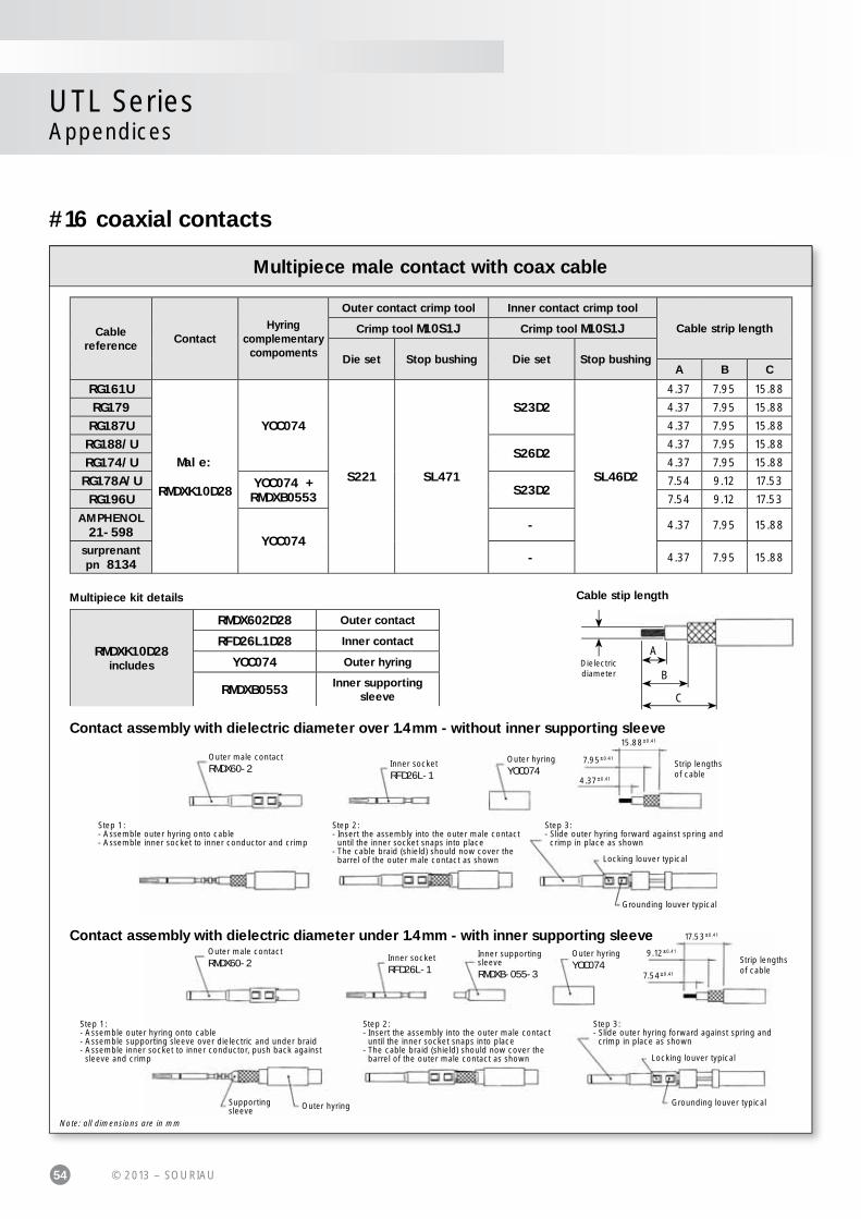
Multipiece male contact with coax cable
UTL SeriesAppendices
Multipiece kit details
RMDXK10D28 includes
RMDX602D28 Outer contact
RFD26L1D28 Inner contact
YOC074 Outer hyring
RMDXB0553 Inner supporting sleeve
Cable stip length
A
B
C
Dielectric diameter
Contact assembly with dielectric diameter over 1.4mm - without inner supporting sleeve
Outer male contactRMDX60-2 Inner socket
RFD26L-1
Outer hyringYOC074
Strip lengths of cable
15.88±0.41
4.37±0.41
7.95±0.41
Step 1:- Assemble outer hyring onto cable- Assemble inner socket to inner conductor and crimp
Step 2:- Insert the assembly into the outer male contact until the inner socket snaps into place- The cable braid (shield) should now cover the barrel of the outer male contact as shown
Step 3:- Slide outer hyring forward against spring and crimp in place as shown
Locking louver typical
Grounding louver typical
Contact assembly with dielectric diameter under 1.4mm - with inner supporting sleeveOuter male contactRMDX60-2 Inner socket
RFD26L-1
Outer hyringYOC074 Strip lengths
of cable
17.53±0.41
7.54±0.41
9.12±0.41Inner supporting sleeveRMDXB-055-3
Step 1:- Assemble outer hyring onto cable- Assemble supporting sleeve over dielectric and under braid- Assemble inner socket to inner conductor, push back against sleeve and crimp
Supporting sleeve Outer hyring
Step 2:- Insert the assembly into the outer male contact until the inner socket snaps into place- The cable braid (shield) should now cover the barrel of the outer male contact as shown
Step 3:- Slide outer hyring forward against spring and crimp in place as shown
Locking louver typical
Grounding louver typical
Note: all dimensions are in mm
#16 coaxial contacts
Cablereference
ContactHyring
complementarycompoments
Outer contact crimp tool Inner contact crimp tool
Cable strip lengthCrimp tool M10S1J Crimp tool M10S1J
Die set Stop bushing Die set Stop bushingA B C
RG161U
Male:
RMDXK10D28
YOC074
S221 SL471
S23D2
SL46D2
4.37 7.95 15.88
RG179 4.37 7.95 15.88
RG187U 4.37 7.95 15.88
RG188/US26D2
4.37 7.95 15.88
RG174/U 4.37 7.95 15.88
RG178A/U YOC074 + RMDXB0553 S23D2
7.54 9.12 17.53
RG196U 7.54 9.12 17.53
AMPHENOL 21-598
YOC074- 4.37 7.95 15.88
surprenant pn 8134 - 4.37 7.95 15.88

55© 2013 – SOURIAU
Multipiece female contact with coax cable
UTL SeriesAppendices
Contact assembly with dielectric diameter over 1.4mm - without inner supporting sleeve
Outer female contactRCDX60-2
Inner pinRMD26L-1
Outer hyringYOC074Strip lengths
of cable
11.13±0.41
4.37±0.41
Step 1:- Assemble outer hyring onto cable- Assemble inner pin to inner conductor and crimp
Step 2:- Insert the assembly into the outer female contact until the inner pin snaps into place- The cable braid (shield) should now cover the barrel of the outer female contact as shown
Step 3:- Slide outer hyring forward against spring and crimp in place as shown
Contact assembly with dielectric diameter under 1.4mm - with inner supporting sleeveOuter female contactRCDX60-2028
Inner pinRMD26L-1
Outer hyringYOC074
Strip lengths of cable
11.13±0.41
6.35±0.41
Supporting sleeveRCDXB-055-1
Supporting sleeveOuter hyring
Step 1:- Assemble outer hyring onto cable- Assemble supporting sleeve over dielectric and under braid- Assemble inner pin to inner conductor, push back against sleeve and crimp
Step 2:- Insert the assembly into the outer female contact until the inner pin snaps into place- The cable braid (shield) should now cover the barrel of the outer female contact as shown
Step 3:- Slide outer hyring forward against spring and crimp in place as shown
RCDXK1D28includes
RCDX602D28 Outer contact
RMD26L1D28 Inner contact
YOC074 Outer hyring
RCDXB0553 Inner supporting sleeve
Multipiece kit details Cable stip length
A
B
C
Dielectric diameter
Cablereference
ContactHyring
complementarycompoments
Outer contact crimp tool Inner contact crimp tool
Cable strip lengthCrimp tool M10S1J Crimp tool M10S1J
Die set Stop bushing Die set Stop bushingA B C
RG161U
Female:
RCDXK1D28
YOC074
S221 SL471
S23D2
SL46D2
4.37
-
11.13RG179 4.37 11.13RG187U 4.37 11.13RG188/U
S26D24.37 11.13
RG174/U 4.37 11.13RG178A/U YOC074 +
RCDXB0553 S23D26.35 11.13
RG196U 6.35 11.13AMPHENOL 21-598
YOC074- 4.37 11.13
surprenant pn 8134 - 4.37 11.13
Note: all dimensions are in mm Ap
pe
ndic
es

56 © 2013 – SOURIAU
Coax cable with monocrimp contact cabling
UTL SeriesAppendices
RCDX60Female coax contact
RMDX60Male coax contact
See cable strip lengths
Cable strip length
A
B
C
• Select appropriate cable and contact combination.• Select appropriate crimp tooling (hand tool, S-die set, stop bushing).• Strip coax cable to the designated wire strip lengths.• Insert the stripped coax into the rear of the contact.• Crimp the contact.
#16 coaxial contacts
Cablereference
Malecontact
Female contact
Crimp tool
Dieset
Stop bushing
Cable strip lengthInner conductor
crimpBraid crimp
A B C g dim t dim g dim t dimCDC PIN22939200 RMDX6046D28 RCDX6016D28
M10S1J
S80 SL105 4.19 5.97 8.51 1.30/1.17 1.40/1.22 2.77/2.64 3.02/2.84
CDC PIN22939200 RMDX6046D28 RCDX6016D28 S87 SL105 5.08 6.35 8.89 1.30/1.17 1.40/1.22 2.77/2.64 3.02/2.84
CDC PIN245670000 RMDX6050D28 RCDX6016D28 S80 SL105 5.08 6.35 8.89 1.30/1.17 1.40/1.22 2.97/2.84 3.12/2.95
KX21TVT (europe)RG178 B/U
RMDX6034D28 RCDX6034D28 S82 SL105 5.08 6.35 8.89 1.30/1.17 1.32/1.17 2.84/2.74 3.07/2.9
RG178 / BU RMDX6050D28 RCDX6016D28 S87 SL105 5.08 6.35 8.89 1.30/1.17 1.40/1.22 2.77/2.64 3.02/2.84
ampex RMDX6032D28 RCDX6032D28 S80 SL105 5.08 6.35 11.68 1.30/1.17 1.40/1.22 2.97/2.84 3.12/2.95
TI PN 920580 RMDX6024D28 RCDX6024D28 S82 SL105 5.08 6.35 8.89 1.35/1.19 1.42/1.27 2.87/2.74 3.07/2.9
RG174/U RMDX6032D28 RCDX6032D28 S80 SL105 5.08 6.35 11.68 1.30/1.17 1.40/1.22 2.97/2.84 3.12/2.95
Honeywell PN 58000062 RMDX6026D28 RCDX6026D28 S82 SL105 5.08 6.35 8.89 1.35/1.19 1.42/1.27 2.87/2.74 3.07/2.9
RG188A/U RMDX6036D28 RCDX6036D28 S80 SL105 5.08 6.35 11.68 1.30/1.17 1.40/1.22 2.97/2.84 3.12/2.95
RG316/U RMDX6036D28 RCDX6036D28 S80 SL105 5.08 6.35 11.68 1.30/1.17 1.40/1.22 2.97/2.84 3.12/2.95
PRD PN247AS-C1123-001
RMDX6018D28 RCDX6018D28 M10SG8 ASSY'YTOOL DIE SETSTOP BUSHINGM10S1J TOOL
5.08 6.35 8.89 1.22/1.17 1.35/1.22 2.92/2.79 3.12/2.97
PRD PN 247AS-C1251 RMDX6018D28 RCDX6018D28 5.08 6.35 8.89 1.22/1.17 1.35/1.22 2.92/2.79 3.12/2.97
raychem 5024A3111 RMDX6052D28 RCDX6052D28 S88 SL105 5.08 6.35 11.68 1.37/1.27 1.45/1.32 2.92/2.79
raychem 5026e1614 RMDX6036D28 RCDX6036D28 M10SG8 ASSY'YTOOL DIE SETSTOP BUSHINGM10S1J TOOL
5.08 6.35 8.89 1.22/1.17 1.35/1.22 2.92/2.79 3.12/2.97
JUDD C15013010902 RMDX6036D28 RCDX6036D28 5.08 6.35 8.89 1.22/1.17 1.35/1.22 2.92/2.79 3.12/2.97
inner cond. #30,braid diam 2.64
RMDX6050D28 - S80 SL105 5.1 6.35 8.9 - - - -
inner cond. #30,braid diam 2.29
RMDX6050D28 - S87 SL105 4.2 6.35 8.5 - - - -
inner cond. #28,braid diam 2.9
RMDX6032D28 RCDX6032D28 S80 SL105 5.1 6.35 11.7 - - - -
inner cond. #26,braid diam 1.78
RMDX6024D28 RCDX6024D28 S82 SL105 5.1 6.35 8.9 - - - -
inner cond. #26,braid diam 3.05
RMDX6026D28 RCDX6026D28 S82 SL105 5.1 6.35 8.9 - - - -
Note: all dimensions are in mm
57© 2013 – SOURIAU
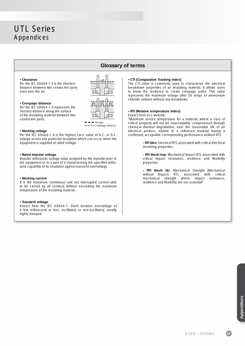
Glossary of terms
UTL SeriesAppendices
• ClearancePer the IEC 60664-1 it is the shortestdistance between two conductive partseven over the air.
• Creepage distancePer the IEC 60664-1 it represents theshortest distance along the surfaceof the insulating material between twoconductive parts.
• Working voltagePer the IEC 60664-1 it is the highest r.m.s. value of A.C. or D.C. voltage across any particular insulation which can occur when the equipment is supplied at rated voltage.
• Rated impulse voltageImpulse withstands voltage value assigned by the manufacturer to the equipment or to a part of it characterizing the specifi ed withs-tand capability of its insulation against transient overvoltage.
• Working currentIt is the maximum continuous and not interrupted current able to be carried by all contacts without exceeding the maximumtemperature of the insulating material.
• Transient voltageExtract from the IEC 60664-1: Short duration overvoltage of a few millisecond or less, oscillatory or non-oscillatory, usuallyhighly damped.
• CTI (Comparative Tracking Index)The CTI value is commonly used to characterize the electrical breakdown properties of an insulating material. It allows users to know the tendency to create creepage paths. This valuerepresents the maximum voltage after 50 drops of ammonium chloride solution without any breakdown.
• RTI (Relative temperature Index):Extract from ULs website:“Maximum service temperature for a material, where a class of critical property will not be unacceptably compromised through chemical thermal degradation, over the reasonable life of anelectrical product, relative to a reference material having aconfi rmed, acceptable corresponding performance defi ned RTI.
- RTI Elec: Electrical RTI, associated with critical electrical insulating properties.
- RTI Mech Imp: Mechanical Impact RTI, associated with critical impact resistance, resilience and fl exibility properties.
- RTI Mech Str: Mechanical Strength (Mechanical without Impact) RTI, associated with critical mechanical strength where impact resistance, resilience and fl exibility are not essential”
Air gapCreepage distance
Ap
pe
ndic
es

58 © 2013 – SOURIAU
UTL SeriesAppendices
Part number IndexMechanicsUTL0103G1P................. P. 14
UTL0103G1P03............... P. 14
UTL0103G1S................. P. 14
UTL0103G1S03............... P. 14
UTL1103G1P................. P. 14
UTL1103G1P03............... P. 14
UTL1103G1S................. P. 14
UTL1103G1S03............... P. 14
UTL6103G1P................. P. 14
UTL6103G1P03............... P. 14
UTL6103G1S................. P. 14
UTL6103G1S03............... P. 14
UTL7103G1P................. P. 14
UTL7103G1P03............... P. 14
UTL7103G1S................. P. 14
UTL7103G1S03............... P. 14
HarnessesHAUTL63G1PS1M.............. P. 14
HAUTL63G1PS2M.............. P. 14
HAUTL63G1SS1M.............. P. 14
HAUTL63G1SS1M.............. P. 14
HAUTL63G1SS2M.............. P. 14
HAUTL63G1SS3M.............. P. 14
HAUTL83G1SPS1M............. P. 14
HAUTL83G1SPS2M............. P. 14
HAUTL83G1SPS3M............. P. 14
HAUTL913G1SPS1M............ P. 14
HAUTL913G1SPS2M............ P. 14
HAUTL913G1SPS3M............ P. 14
AccessoriesSWSFILLERPLUG.............. P. 16
UTL103G1PDCG68............. P. 16
UTL103G1SDCG68............. P. 16
UTL10DCG................... P. 16
UTL610DCG.................. P. 16
ContactsRC14M25K................... P. 23
RC14M30K................... P. 23
RC16M23K................... P. 23
RC16M25K................... P. 23
RC20M12K................... P. 23
RC20M13K................... P. 23
RC24M9K.................... P. 23
RC28M1K.................... P. 23
RCDX6015D28................ P. 51
RCDX6016D28................ P. 50
RCDX6018D28................ P. 50
RCDX6019D28................ P. 51
RCDX6024D28................ P. 50
RCDX6026D28................ P. 50
RCDX602D28................. P. 55
RCDX6031D28................ P. 51
RCDX6032D28................ P. 50
RCDX6034D28................ P. 50
RCDX6036D28................ P. 50
RCDX6052D28................ P. 50
RCDXB0553.................. P. 55
RCDXK1D28.................. P. 50
RFD26L1D28................. P. 54
RM14M25K................... P. 23
RM14M30K................... P. 23
RM16M23K................... P. 23
RM16M25K................... P. 23
RM20M12K................... P. 23
RM20M13K................... P. 23
RM24M9K.................... P. 23
RM28M1K.................... P. 23
RMD26L1D28................. P. 55
RMDX6015D28................ P. 51
RMDX6018D28................ P. 50
RMDX6019D28................ P. 51
RMDX602D28................. P. 54
RMDX6024D28................ P. 50
RMDX6026D28................ P. 50
RMDX6031D28................ P. 51
RMDX6032D28................ P. 50
RMDX6034D28................ P. 50
RMDX6036D28................ P. 50
RMDX6046D28................ P. 50
RMDX6050D28................ P. 50
RMDX6052D28................ P. 50
RMDXB0553.................. P. 54
RMDXK10D28................. P. 50
SC14M1S18.................. P. 23
SC14ML1S18................. P. 23
SC14M1TK6.................. P. 23
SC14ML1TK6................. P. 23
SC16M1S18.................. P. 23
SC16M11S18................. P. 23
SC16ML1S18................. P. 23
SC16ML11S18................ P. 23
SC16M1TK6.................. P. 23
SC16M11TK6................. P. 23
SC16ML1TK6................. P. 23
SC16ML11TK6................ P. 23
SC20M1S18.................. P. 23
SC20ML1S18................. P. 23
SC20M1TK6.................. P. 23
SC20ML1TK6................. P. 23
SC24M1S18.................. P. 23
SC24ML1S18................. P. 23
SC24M1TK6.................. P. 23
SC24ML1TK6................. P. 23
SM14M1S18.................. P. 23
SM14ML1S18................. P. 23
SM14M1TK6.................. P. 23
SM14ML1TK6................. P. 23
SM16M1S18.................. P. 23
SM16M11S18................. P. 23
SM16ML1S18................. P. 23
SM16ML11S18................ P. 23
SM16M1TK6.................. P. 23
SM16M11TK6................. P. 23
SM16ML1TK6................. P. 23
SM16ML11TK6................ P. 23
SM20M1S18.................. P. 23
SM20ML1S18................. P. 23
SM20M1TK6.................. P. 23
SM20ML1TK6................. P. 23
SM24M1S18.................. P. 23
SM24ML1S18................. P. 23
SM24M1TK6.................. P. 23
SM24ML1TK6................. P. 23
YOC074..................... P. 54
ToolingM10S1J..................... P. 52
M10SG8..................... P. 53
RTM205..................... P. 33
RX2025GE1.................. P. 29
S16RCM14................... P. 29
S16RCM1425 ................ P. 29
S16RCM16................... P. 29
S16RCM1625................. P. 29
S16RCM20................... P. 29
S16SCM20................... P. 29
S16SCML1................... P. 29
S16SCML11.................. P. 29
S221....................... P. 54
S23D2...................... P. 54
S26D2...................... P. 54
S471....................... P. 54
S80........................ P. 53
S83........................ P. 53
S82........................ P. 56
S87........................ P. 56
SL105...................... P. 53
SL46D2..................... P. 54
Shandles................... P. 29


Connection Technologies
IND
UTL
CA
01
EN
© C
opyr
ight
SO
UR
IAU
2013
- A
ll in
form
atio
n in
thi
s do
cum
ent
pres
ents
onl
y ge
nera
l par
ticul
ars
and
shal
l not
form
par
t of
any
con
trac
t. A
ll rig
hts
rese
rved
to
SOU
RIA
U fo
r ch
ange
s w
ithou
t pr
ior
notifi
cat
ion
or p
ublic
ann
ounc
emen
t. A
ny d
uplic
atio
n is
pro
hibi
ted,
unl
ess
appr
oved
in w
ritin
g.