utility models self-propelled belt drive · pdf fileutility models self-propelled belt drive...
TRANSCRIPT
UTILITY MODELS SELF-PROPELLED BELT DRIVE
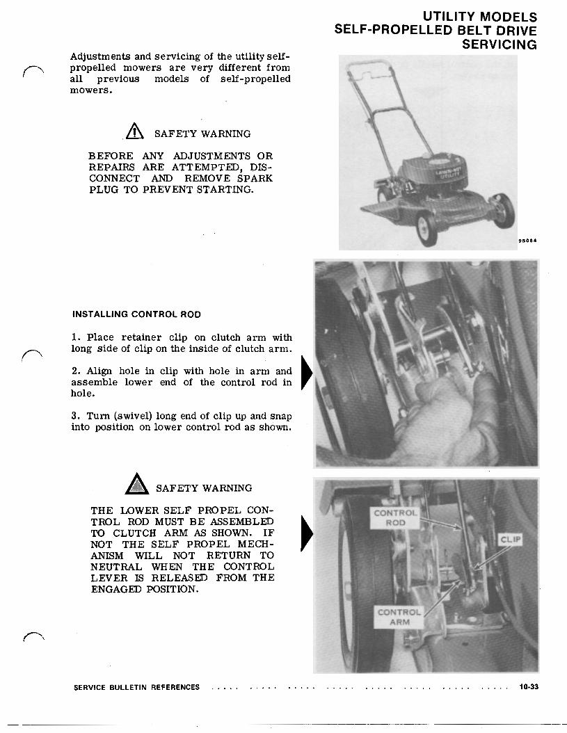
SERVICING Adjustments and servicing of the utility self- propelled mowers are very different from all previous models of self-propelled mowers.
SAFETY WARNING
BEFORE ANY ADJUSTMENTS OR
CONNECT AND REMOVE SPARK PLUG TO PREVENT STARTING.
REPAIRS ARE ATTEMPTED, DIS-
95064
INSTALLING CONTROL ROD
1. Place retainer clip on clutch arm with long side of clip on the inside of clutch arm.
2. Align hole in clip with hole in arm and assemble lower end of the control rod in hole.
3. Turn (swivel) long end of clip up and snap into position on lower control rod as shown.
THE LOWER SELF PROPEL CON- TROL ROD MUST BE ASSEMBLED TO CLUTCH ARM AS SHOWN. I F NOT THE SELF PROPEL MECH- ANISM WILL NOT RETURN TO NEUTRAL WHEN THE CONTROL LEVER IS RELEASED FROM THE ENGAGED POSITION.
SERVICE BULLETIN REFERENCES 10-33
UTILITY MODELS
SERVICING SELF-PROPELLED BELT DRIVE
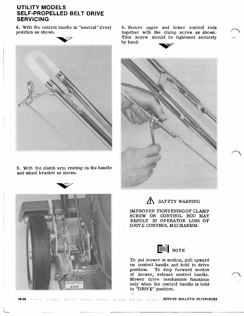
4. With the control handle in "neutral" (free) position a s shown.
5. With the clutch arm resting on the handle and wheel bracket as shown.
10-34
6. Secure upper and lower control rods together with the clamp screw as shown. This screw should be tightened securely by hand.
SAFETY WARNING
IMPROPER TIGHTENING OF CLAMP SCREW ON CONTROL ROD MAY RESULT IN OPERATOR LOSS OF DRIVE CONTROL MECHANISM.
To put mower in motion, pull upward on control handle and hold in drive position. To stop forward motion of mower, release control handle. Mower drive mechanism functions only when the control handle is held in "DRIVE" position.
SERVICE BULLETIN REFERENCES

DRIVE ROLLER ADJUSTMENT
1. With the control handle in "Neutral", place both rear wheel height adjusters in #1 (lowest) cutting position as shown. A gap of 3/16" should appear between the drive rollers and tires.
2. Loosen bolt and nut located in drive roller gap adjusting slot on each side of drive roller bracket.
3. Move the drive roller bracket up o r down to obtain the necessary 3/16'' drive roller gap. Hold bracket in position and tighten both bolts and nuts securely.
UTILITY MODELS
SERVICING SELF-PROPELLED BELT DRIVE
ENGINE REMOVAL OR REPLACEMENT
SAFETY WARNING
TO PREVENT STARTING OF EN- GINE, DISCONNECT AND REMOVE SPARK PLUG PRIOR TO REMOVING THE ENGINE.
1. Remove blade bolt, washer, blade stiffener, collar and three bolts securing muffler and remove muffler.
2. Remove three bolts securing engine to muffler plate and remove engine.
Do not remove muffler plate from housing when removing engine.
SERVICE BULLETIN REFERENCES 10-35
UTILITY MODELS
SERVICING SELF-PROPELLED BELT DRIVE
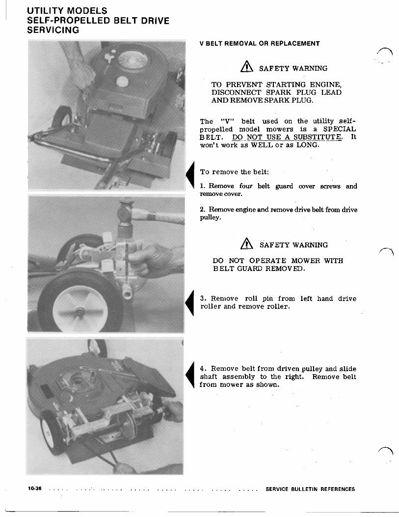
V BELT REMOVAL OR REPLACEMENT
SAFETY WARNING
TO PREVENT STARTING ENGINE, DISCONNECT SPARK PLUG LEAD AND REMOVE SPARK PLUG.
The "V" belt used on the utility self- propelled model mowers is a SPECIAL BELT. DO NOT USE A SUBSTITUTE. It won't work a s WELL o r a s LONG.
To remove the belt:
1. Remove four belt guard cover screws and remove cover.
2. Remove engine and remove drive belt from drive pulley.
SAFETY WARNING
DO NOT OPERATE MOWER WITH BELT GUARD REMOVED.
3. Remove roll pin from left hand drive roller and remove roller.
4. Remove belt from driven pulley and slide shaft assembly to the right. Remove belt from mower as shown.
10-36 SERVICE BULLETIN REFERENCES
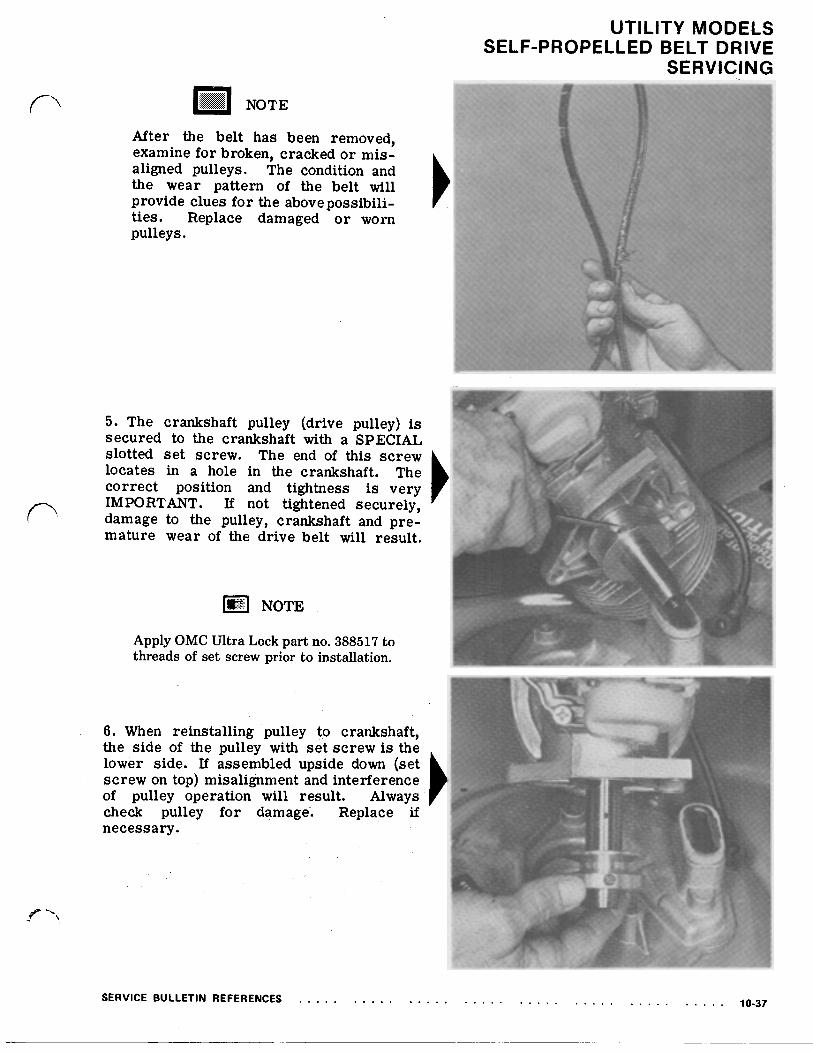
After the belt has been removed, examine for broken, cracked or mis- aligned pulleys. The condition and the wear pattern of the belt will provide clues for the above possibili- ties. Replace damaged o r worn pulleys.
5. The crankshaft pulley (drive pulley) is secured to the crankshaft with a SPECIAL slotted set screw. The end of this screw locates in a hole in the crankshaft. The correct position and tightness is very IMPORTANT. If not tightened securely, damage to the pulley, crankshaft and pre- mature wear of the drive belt will result.
Apply OMC Ultra Lock part no. 388517 to threads of set screw prior to installation.
UTILITY MODELS
SERVICING SELF-PROPELLED BELT DRIVE
6. When reinstalling pulley to crankshaft, the side of the pulley with s e t screw is the lower side. If assembled upside down (set screw on top) misalignment and interference of pulley operation will result. Always check pulley for damage-. Replace if necessary.
UTILITY MODELS
SERVICING SELF-PROPELLED BELT DRIVE
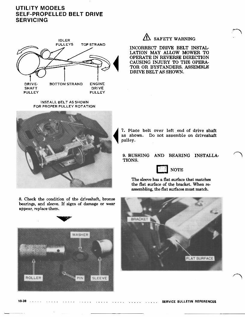
IDLER SAFETY WARNING PULLEYS TOP STRAND
INCORRECT DRIVE BELT INSTAL LATION MAY ALLOW MOWER TO OPERATE IN REVERSE DIRECTION
TOR OR BYSTANDERS. ASSEMBLE DRIVE BELT AS SHOWN.
CAUSING INJURY TO THE OPERA-
DRIVE- BOTTOM STRAND ENGINE SHAFT DRIVE PULLEY PULLEY
INSTALL BELT AS SHOWN FOR PROPER PULLEY ROTATION
8. Check the condition of the driveshaft, bronze bearings, and sleeve. If signs of damage or wear appear, replace them.
7. Place belt over left end of drive shaft 'as shown. Do not assemble on driveshaft pulley.
9. BUSHING AND BEARING INSTALLA- TIONS.
NOTE
The sleeve has a flat surface that matches the flat surface of the bracket. When re- assembling, the flat surfaces must match.
10-38 SERVICE BULLETIN REFERENCES
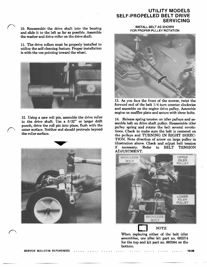
10. Reassemble the drive shaft into the bearing and slide it to the left as far as possible. Assemble the washer and drive roller on the drive shaft.
11. The drive rollers must be properly installed to utilize the self-cleaning feature. Proper installation is with the vee pointing toward the wheel.
12. Using a new roll pin, assemble the drive roller to the drive shaft. Use a 5/32” or larger drift punch, drive the roll pin into place, flush with the outer surface. Neither end should protrude beyond the roller surface.
UTILITY MODELS
SERVICING SELF-PROPELLED BELT DRIVE
INSTALL BELT AS SHOWN FOR PROPER PULLEY ROTATION
13. As you face the front of the mower, twist the forward end of the belt 1/4 turn counter clockwise and assemble on the engine drive pulley. Assemble engine on muffler plate and secure with three bolts.
14. Release spring tension on idler pulleys and as- semble belt on drive shaft pulley. Reassemble idler pulley spring and rotate the belt several revolu- tions. Check to make sure the belt is centered on the pulleys and TURNING IN RIGHT DIREC- TION. Note direction of arrow on large pulley in illustration above. Check and adjust belt tension if necessary. Refer to BELT TENSION ADJUSTMENT.
SERVICE BULLETIN REFERENCES
NOTE When replacing either of the belt idler assemblies, use idler kit part no. 682374 for the top and kit part no. 682564 on the bottom.
10-39

UTILITY MODELS
SERVICING SELF-PROPELLED BELT DRIVE
BELT TENSION ADJUSTMENT
1. Check drive belt installation. Drive belt must be installed between idler pulleys as shown.
2. Drive belt should be checked to insure that proper tension exists in order to pre- vent premature belt failure. Lift floating idler from the upper strand of "V" belt. Belt will then become loose. Set floating idler onto "V" belt and check clearance be- tween the two strands of the "V" belt. ,The distance between the two strands should not be less than 1/2" a s shown.
3 . To adjust belt tension; loosen four handle bracket mounting screws (two on each bracket) and two screws (one on each side) located on the sides of rear height adjuster bracket as shown. Slide entire self-propell- ing mechanism in direction necessary to obtain the proper "V" belt tension.
4. Care should be taken to insure that both sides of the self-propelling mechanism a r e positioned equally on the mower housing. This can be accomplished by measuring the distance from the front edge on the height adjuster brackets to the 1/4" diameter gage holes located directly in front of these brackets as shown. This distance must be the same for both sides. Before tightening screws make sure the distance between the strands of the "V" belt is not less than 1/2". Tighten the four handle bracket screws and the two side screws securely. Reassemble belt guard to- self-propel mechanism using screws previously removed.
SAFETY WARNING DO NOT OPERATE MOWER WITH BELT GUARD REMOVED.
10-40 SERVICE BULLETIN REFERENCES

LUBRICATION
10 HOURS
1. DRIVE ROLLER BEARINGS-Disassemble rotating shaft cover from self-propel mechanism by removing four screws. Unscrew plug from end of each drive roller (Point “A”). Fill exposed cavity
610721 OR EQUIVALENT. Replace plug and tighten until snug. Repeat procedure until lubri- cant appears on cross-shaft at Point “B”. Reas- semble rotating shaft cover to self-propel assembly.
with LAWN-BOY “A” GREASE, PART NO.
UTILITY MODELS
SERVICING SELF-PROPELLED BELT DRIVE
OLD STYLE LOWER IDLER ASSEMBLY
FLOATING IDLER PULLEY-Do not immerse the idler pulley in solvent. Use a rag containing solvent, clean the hole in the idler pulley and the shoulder bolt thoroughly. Useing a small amount of LAWN-BOY A GREASE or EQUIVALENT, re- lubricate the shoulder bolt and remount idler pulley assembly in the same order it was originally.
AS REQUIRED
1. CLUTCH LINKAGE-Apply several drops of light machine oil on clutch mechanism at all pivoting points.
SERVICE BULLETIN REFERENCES
PLASTIC BOLT-PULLEY-ARM-NUT The lower idler pulley on 8600 and 8601 models were plastic. It should not be lubricated after being removed and cleaned up. Never immerse plastic pulleys in solvent. Use a rag containing solvent to clean. If damaged and/or worn, replace with kit part no. 682564.
LOWER IDLER ASSEMBLY NEW STYLE
PART #682564 BOLT-PULLEY-ARM-NUT
LOWER IDLER PULLEY Permanently lubri- cated. No lubrication required.
10-41

UTILITY MODELS 4500,4501, 8600,8601 BLADE SERVICING
NOTE
BLADE ASSEMBLY
A totally new and different method of retain- ing the blade is used on the 20" utility model mowers.
The blade bolt, part no. 609960, is special with a SPECIFIC HARDNESS AND STRENGTH. The blade lockwasher, part no. 605339, is also special.
The lockwasher must be installed with TORQUE BLADE BOLT TO cupped surface and triangular points mounted 30-32 FT. LBS. toward the blade.
SAFETY WARNING
THE LOCKWASHER AND BLADE BOLT MUST BE REPLACED AFTER
STALLED FOUR (4) TIMES. THE LOCKING FEATURE OF THE LOCK- WASHER AND BLADE BOLT WILL HAVE DECREASED AND BLADE COULD LOOSEN IF REPLACEMENT IS NOT MADE.
BEING REMOVED AND REIN-
10-42 SERVICE BULLETIN REFERENCES

UTILITY MODELS 8602 AND LATER SELF-PROPELLED SERVICING On 4502,8602 and later models of Utility mowers, a blade nut has replaced the blade bolt previously used on earlier models.
SAFETY WARNING
THE BLADE NUT MUST BE RE- PLACED AFTER BEING REMOVED AND REINSTALLED FOUR (4) TIMES. THE LOCKING FEATURE OF THE BLADE NUT WILL HAVE DECREASED AND BLADE COULD LOOSEN IF REPLACEMENT IS NOT MADE.
1. Collar 4. Blade 2. Stiffener 5. Nut 3. Washer (20 and 21 inch
models only)
A blade collar that was damaged and bent when being removed from crankshaft should always be replaced. If not replaced, a vibration in the mower and a rough, uneven or ragged cutting may result. KEEP BLADE SHARP AND BALANCED
Before assembling collar on crankshaft, check to be sure it did not get bent or distorted when being removed. If so, replace it. Do not use, because, it will cause vibration.
If the blade nut is to be re-used, clean the threads thoroughly. Also clean threads on crank shaft. Apply OMC Ultra-Lock Part No. 388517 on the threads.
NOTE
When installing blade after sharpening and balance, torque blade nut to 45-50 ft. lbs.
SAFETY WARNING
ALWAYS USE ORIGINAL EQUIP- MENT REPLACEMENT BLADE AND
SURE COMPLIANCE WITH SAFETY
STALLING BLADE, BE SURE PARTS ARE REPLACED IN THE SAME SE- QUENCE IN WHICH THEY WERE REMOVED. ALWAYS REPLACE BLADE WITH CURVED EDGE UP (TOWARD HOUSING).
ATTACHMENT HARDWARE TO IN-
SPECIFICATIONS. WHEN REIN-
10-43