using the mindi power management simulator tool
TRANSCRIPT
© 2007 Microchip Technology Inc. DS01085A-page 1
AN1085
INTRODUCTIONMicrochip’s Mindi™ Simulator Tool aids in the designand analysis of various analog circuits used in PowerManagement and Linear applications.
This interactive simulator tool enables designers toquickly generate circuit diagrams, simulate circuits andspecify passive components for a variety of power,battery-charger and linear applications. Circuitsdeveloped using the Mindi™ simulation tool can bedownloaded to a personal computer (PC) orworkstation and can often be ported directly intosystem diagrams.
This application note describes how to use the PowerManagement circuit design and analysis portion of theMindi Design Tool, and serves as a tutorial forsimulating a Power Management application circuit.
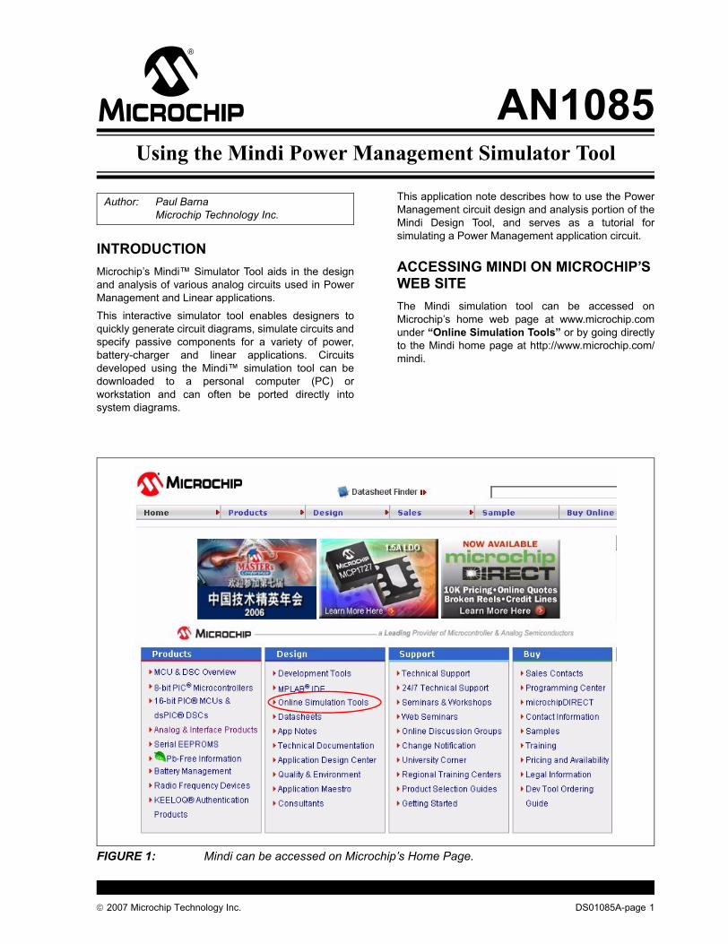
ACCESSING MINDI ON MICROCHIP’S WEB SITEThe Mindi simulation tool can be accessed onMicrochip’s home web page at www.microchip.comunder “Online Simulation Tools” or by going directlyto the Mindi home page at http://www.microchip.com/mindi.
FIGURE 1: Mindi can be accessed on Microchip’s Home Page.
Author: Paul BarnaMicrochip Technology Inc.
Using the Mindi Power Management Simulator Tool

AN1085
DS01085A-page 2 © 2007 Microchip Technology Inc.
The Mindi home page is shown in Figure 2. To enter theMindi Simulator Tool, select the “Click Here” button inthe upper left hand corner of the window.
FIGURE 2: Bring up the Mindi Simulator Tool by selecting “Click Here” on the Mindi Home Page.The first time Mindi is accessed, the user will beprompted to provide some basic registrationinformation.
Once registered, an account is created on the HostServer and users will be able to generate and analyzedesigns on the Mindi Design Tool web page. Customdesigns can also be saved to their PC, where they canbe accessed for future reference.
Once the user logs into Mindi, the “Application Circuit”menu is displayed indicating the Circuits that are avail-able for design and simulation, as shown in Figure 3.
FIGURE 3: Select the Application Circuit on the “Application Circuit” page
Note: If a “pop-up blocker” is enabled on theuser’s browser, then there may be a prob-lem with the registration process. Pleasebe sure to disable this feature when regis-tering on Mindi. On Internet Explorer, thismay be done by selecting the Pop-UpBlocker window under the Tools pull-downmenu.

© 2007 Microchip Technology Inc. DS01085A-page 3
AN1085
CIRCUIT SIMULATION STEPSThe Mindi Simulator Tool is divided into four sections or“circuit simulation steps”, making it easy to choose theright circuit for your application. Once an ApplicationCircuit is selected, the Mindi Simulator Tool will guidethe user through choosing a circuit configuration,generating a complete circuit solution and performingsimulations to analyze the circuit behavior.
The four circuit simulation steps are represented byfour page tabs at the top of the window display after theinitial Application Circuit is selected. They are:
1. Application Circuit.2. Input Requirements.3. Analyze.4. Bill Of Materials.
Figure 4 illustrates the four tabs in the Mindi SimulatorTool.
FIGURE 4: Four tabs step the user through a circuit design.
Application CircuitThe Application Circuit tab brings up the “ApplicationCircuit” page, shown in Figure 3. The Mindi simulatortool defaults to this page after the user logs on to thetool. On this page, one of the major Application Circuitscan be selected. For Power Management, there aretwo Application Circuits, “Battery Chargers” or “DC-to-DC Converters”.
After the user has selected one of these ApplicationCircuits, Mindi will display the next tab, InputRequirements.

AN1085
DS01085A-page 4 © 2007 Microchip Technology Inc.
Input RequirementsThe Input Requirements tab brings up the CircuitConfiguration shown in Figure 5 and Figure 6. The usercan select the appropriate circuit configuration andspecify operating parameters on this page.
FIGURE 5: Select the Circuit Configuration on the “Input Requirements” pageIn the example shown in Figure 5, the generalapplication, “Integrated DC/DC 1A Regulator” hasbeen selected. The list of Configuration Circuits can beviewed in the pull-down window on the “InputRequirements” tab.
When a Circuit Configuration is selected, a descriptionof the circuit is displayed, along with circuit inputrequirements and a block diagram of the circuitsolution, as shown in Figure 6.
FIGURE 6: All Circuit Configurations provide a Circuit Description, Block Diagram and user-defined Input Requirements.
© 2007 Microchip Technology Inc. DS01085A-page 5
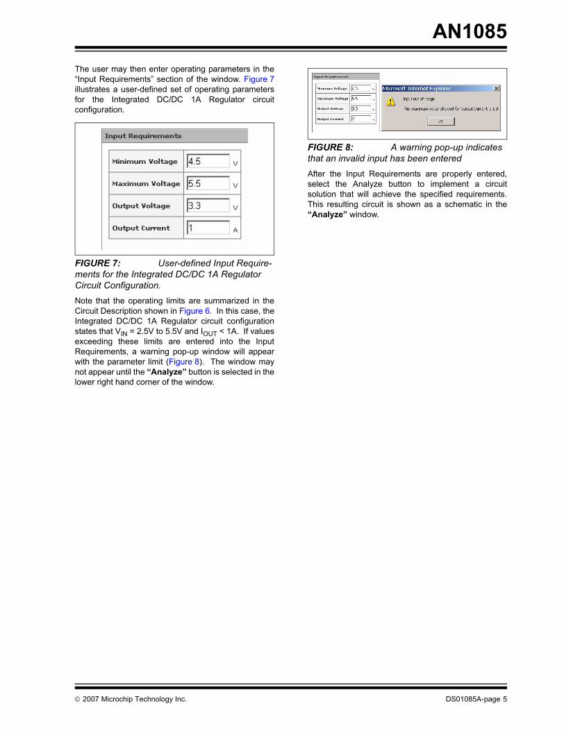
AN1085The user may then enter operating parameters in the“Input Requirements” section of the window. Figure 7illustrates a user-defined set of operating parametersfor the Integrated DC/DC 1A Regulator circuitconfiguration.
FIGURE 7: User-defined Input Require-ments for the Integrated DC/DC 1A Regulator Circuit Configuration.Note that the operating limits are summarized in theCircuit Description shown in Figure 6. In this case, theIntegrated DC/DC 1A Regulator circuit configurationstates that VIN = 2.5V to 5.5V and IOUT < 1A. If valuesexceeding these limits are entered into the InputRequirements, a warning pop-up window will appearwith the parameter limit (Figure 8). The window maynot appear until the “Analyze” button is selected in thelower right hand corner of the window.
FIGURE 8: A warning pop-up indicates that an invalid input has been enteredAfter the Input Requirements are properly entered,select the Analyze button to implement a circuitsolution that will achieve the specified requirements.This resulting circuit is shown as a schematic in the“Analyze” window.
AN1085
DS01085A-page 6 © 2007 Microchip Technology Inc.
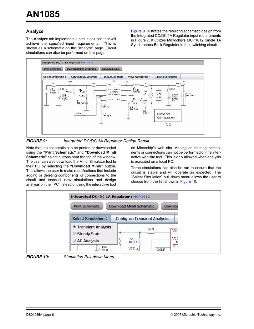
AnalyzeThe Analyze tab implements a circuit solution that willachieve the specified input requirements. This isshown as a schematic on the “Analyze” page. Circuitsimulations can also be performed on this page.
Figure 9 illustrates the resulting schematic design fromthe Integrated DC/DC 1A Regulator input requirementsin Figure 7. It utilizes Microchip’s MCP1612 Single 1ASynchronous Buck Regulator in the switching circuit.
FIGURE 9: Integrated DC/DC 1A Regulator Design Result.Note that the schematic can be printed or downloadedusing the “Print Schematic” and “Download MindiSchematic” select buttons near the top of the window.The user can also download the Mindi Simulator tool totheir PC by selecting the “Download Mindi” button.This allows the user to make modifications that includeadding or deleting components or connections to thecircuit and conduct new simulations and designanalysis on their PC instead of using the interactive tool
on Microchip’s web site. Adding or deleting compo-nents or connections can not be performed on the inter-active web site tool. This is only allowed when analysisis executed on a local PC.
Three simulations can also be run to ensure that thecircuit is stable and will operate as expected. The“Select Simulation” pull-down menu allows the user tochoose from the list shown in Figure 10.
FIGURE 10: Simulation Pull-down Menu.

© 2007 Microchip Technology Inc. DS01085A-page 7
AN1085TRANSIENT ANALYSISThe Transient Analysis simulation will analyze thecircuit response to an applied step to the load current.
Once this simulation is selected, the user will be able todefine the characteristics of the load step current bydouble-clicking on the LOAD symbol in the schematic,as shown in Figure 11.
FIGURE 11: Select the Current Load symbol to modify the Load Step Current.The user can then define the Load Step characteristicsin the Load Step pop-up window, as shown inFigure 12.
FIGURE 12: Current Load Step Pop-up Window.
The length of the simulation can be specified by select-ing the “Configure Transient Analysis” button.Figure 13 shows the configuration pop-up window for aTransient Analysis simulation. This pop-up windowallows the user to specify the length of time that theTransient Analysis simulation will run. Note that theactual time it takes Mindi to complete the simulation isaffected by the length of time specified in this window.
FIGURE 13: Configure Simulation pop-up window for Transient Analysis simulation.

AN1085
DS01085A-page 8 © 2007 Microchip Technology Inc.
Once the simulation time has been set, then the “RunTransient Analysis” button can be selected. While thesimulation is running, the “Run Transient Analysis”button will be grayed out, with the message “RunningTransient Analysis” displayed, as indicated inFigure 14. The button returns to its normal state whenthe simulation is complete.
FIGURE 14: The “Run Transient Analysis” message is displayed while the simulator is running.
The signal waveform can then be displayed byselecting the “View Waveforms” pull-down menu. Anexample of the waveform analysis is shown inFigure 15. This waveform shows the transientresponse of the regulated output voltage (blue wave-form) when the current load (purple waveform) isstepped from 0 Amps to 0.5 Amps with a rise time of100 usec. Many other signal waveforms are alsoavailable for viewing and can enabled or disabled in thewaveform viewer.
In more complicated circuits, the waveforms are groupinto four categories (output, switching, input, andsignal). By looking at the probe’s name, one can easilytell which waveform grouping the probe is located.
FIGURE 15: Waveform Viewer showing Current Load Step and Output Voltage Response.
Current Load Step
Output Voltage Response

© 2007 Microchip Technology Inc. DS01085A-page 9
AN1085STEADY STATE ANALYSISThe Steady State Analysis can be selected in theSimulation pull-down menu shown in Figure 10. Thisanalysis will generate circuit waveforms under steadystate conditions. The user can use this analysis tounderstand what is happening at various points in thecircuit while modifying Input Voltage and Load Current.
In Figure 16, VIN and ILOAD have been modified to 4.5Vand 1A, respectively. The waveform shown inFigure 17 illustrates the voltage at the LX pin of thedevice (LX, red waveform), the current coming out ofthe inductor (IL1, purple waveform) and the regulatedoutput voltage (VOUT, bold red waveform).
FIGURE 16: Modifying VIN and ILOAD for Steady State analysis.
FIGURE 17: Waveform Viewer showing Voltage output (VOUT), LX output (LX) and current out of the inductor (IL1) during Steady State Analysis.
LX
VOUT
IL1

AN1085
DS01085A-page 10 © 2007 Microchip Technology Inc.
AC ANALYSISThe AC Analysis can be selected in the Simulation pull-down menu shown in Figure 10. This analysis will gen-erate a Bode plot showing the small signal response ofthe system. The small signal response is generated byinjecting a small signal stimulus into the feedback loop
of the DC-DC converter device. The user can use thisanalysis to understand system DC gain, bandwidth,and overall stability.
When AC Analysis is selected, an AC Voltage Sourceand Bode Analyzer symbol will appear in theschematic, as shown in Figure 18. This indicates wherethe AC signal is injected in the feedback loop.
FIGURE 18: AC Voltage Source and Bode Analyzer shown on schematic during AC Analysis.The length of the simulation can be specified by select-ing the “Configure AC Analysis” button. Figure 20shows the configuration pop-up window for an ACanalysis simulation. This pop-up window allows theuser to specify the frequency range that the Analysiswill sweep through.
FIGURE 19: Configure AC Analysis Pop-up Window.
© 2007 Microchip Technology Inc. DS01085A-page 11
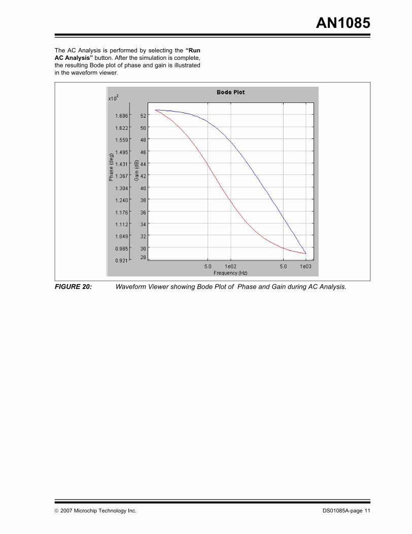
AN1085The AC Analysis is performed by selecting the “RunAC Analysis” button. After the simulation is complete,the resulting Bode plot of phase and gain is illustratedin the waveform viewer.
FIGURE 20: Waveform Viewer showing Bode Plot of Phase and Gain during AC Analysis.

AN1085
DS01085A-page 12 © 2007 Microchip Technology Inc.
Bill of Materials (BOM)The Bill of Materials tab displays a list ofcomponents used in the circuit solution. The BOMcompliments the schematic shown on theAnalyze tab. The BOM can be saved to the user’sPC by selecting the “Download Excel BOM”button, as shown in Figure 21.
FIGURE 21: Bill of Materials Tab.There are also two other buttons on this page. The“Order Device” button will link the user to theMicrochip product web page of the device used toimplement the simulator design. Among other things,the user can order a device sample or download thedata sheet, related app notes, etc., on this web page.The “Order Eval Board” button will link the user to theMicrochip eval board web page of a generic evaluationboard solution for the simulated circuit. This boardrepresents a circuit using default component valuesand can serve as a platform for evaluating the circuit onthe bench.
CONCLUSIONThe Mindi Simulator Tool allows system engineers toquickly design and evaluate power management andlinear circuits, saving time with circuit development andselecting the right components. In this application note,an overview of the Power Management circuitsavailable for simulation was provided and the keysimulation functions were discussed. The user wasthen stepped through a circuit simulation example.This should allow system engineers to quickly come upto speed with the Mindi Simulator Tool and benefit fromthe features that the tool provides.
© 2007 Microchip Technology Inc. DS01085A-page 13
Information contained in this publication regarding deviceapplications and the like is provided only for your convenienceand may be superseded by updates. It is your responsibility toensure that your application meets with your specifications.MICROCHIP MAKES NO REPRESENTATIONS ORWARRANTIES OF ANY KIND WHETHER EXPRESS ORIMPLIED, WRITTEN OR ORAL, STATUTORY OROTHERWISE, RELATED TO THE INFORMATION,INCLUDING BUT NOT LIMITED TO ITS CONDITION,QUALITY, PERFORMANCE, MERCHANTABILITY ORFITNESS FOR PURPOSE. Microchip disclaims all liabilityarising from this information and its use. Use of Microchipdevices in life support and/or safety applications is entirely atthe buyer’s risk, and the buyer agrees to defend, indemnify andhold harmless Microchip from any and all damages, claims,suits, or expenses resulting from such use. No licenses areconveyed, implicitly or otherwise, under any Microchipintellectual property rights.
Trademarks
The Microchip name and logo, the Microchip logo, Accuron, dsPIC, KEELOQ, KEELOQ logo, microID, MPLAB, PIC, PICmicro, PICSTART, PRO MATE, PowerSmart, rfPIC, and SmartShunt are registered trademarks of Microchip Technology Incorporated in the U.S.A. and other countries.
AmpLab, FilterLab, Linear Active Thermistor, Migratable Memory, MXDEV, MXLAB, PS logo, SEEVAL, SmartSensor and The Embedded Control Solutions Company are registered trademarks of Microchip Technology Incorporated in the U.S.A.
Analog-for-the-Digital Age, Application Maestro, CodeGuard, dsPICDEM, dsPICDEM.net, dsPICworks, ECAN, ECONOMONITOR, FanSense, FlexROM, fuzzyLAB, In-Circuit Serial Programming, ICSP, ICEPIC, Mindi, MiWi, MPASM, MPLAB Certified logo, MPLIB, MPLINK, PICkit, PICDEM, PICDEM.net, PICLAB, PICtail, PowerCal, PowerInfo, PowerMate, PowerTool, REAL ICE, rfLAB, rfPICDEM, Select Mode, Smart Serial, SmartTel, Total Endurance, UNI/O, WiperLock and ZENA are trademarks of Microchip Technology Incorporated in the U.S.A. and other countries.
SQTP is a service mark of Microchip Technology Incorporated in the U.S.A.
All other trademarks mentioned herein are property of their respective companies.
© 2007, Microchip Technology Incorporated, Printed in the U.S.A., All Rights Reserved.
Printed on recycled paper.
Note the following details of the code protection feature on Microchip devices:• Microchip products meet the specification contained in their particular Microchip Data Sheet.
• Microchip believes that its family of products is one of the most secure families of its kind on the market today, when used in the intended manner and under normal conditions.
• There are dishonest and possibly illegal methods used to breach the code protection feature. All of these methods, to our knowledge, require using the Microchip products in a manner outside the operating specifications contained in Microchip’s Data Sheets. Most likely, the person doing so is engaged in theft of intellectual property.
• Microchip is willing to work with the customer who is concerned about the integrity of their code.
• Neither Microchip nor any other semiconductor manufacturer can guarantee the security of their code. Code protection does not mean that we are guaranteeing the product as “unbreakable.”
Code protection is constantly evolving. We at Microchip are committed to continuously improving the code protection features of ourproducts. Attempts to break Microchip’s code protection feature may be a violation of the Digital Millennium Copyright Act. If such actsallow unauthorized access to your software or other copyrighted work, you may have a right to sue for relief under that Act.
Microchip received ISO/TS-16949:2002 certification for its worldwide headquarters, design and wafer fabrication facilities in Chandler and Tempe, Arizona, Gresham, Oregon and Mountain View, California. The Company’s quality system processes and procedures are for its PIC®
MCUs and dsPIC® DSCs, KEELOQ® code hopping devices, Serial EEPROMs, microperipherals, nonvolatile memory and analog products. In addition, Microchip’s quality system for the design and manufacture of development systems is ISO 9001:2000 certified.

DS01085A-page 14 © 2006 Microchip Technology Inc.
AMERICASCorporate Office2355 West Chandler Blvd.Chandler, AZ 85224-6199Tel: 480-792-7200 Fax: 480-792-7277Technical Support: http://support.microchip.comWeb Address: www.microchip.comAtlantaDuluth, GA Tel: 678-957-9614 Fax: 678-957-1455BostonWestborough, MA Tel: 774-760-0087 Fax: 774-760-0088ChicagoItasca, IL Tel: 630-285-0071 Fax: 630-285-0075DallasAddison, TX Tel: 972-818-7423 Fax: 972-818-2924DetroitFarmington Hills, MI Tel: 248-538-2250Fax: 248-538-2260KokomoKokomo, IN Tel: 765-864-8360Fax: 765-864-8387Los AngelesMission Viejo, CA Tel: 949-462-9523 Fax: 949-462-9608Santa ClaraSanta Clara, CA Tel: 408-961-6444Fax: 408-961-6445TorontoMississauga, Ontario, CanadaTel: 905-673-0699 Fax: 905-673-6509
ASIA/PACIFICAsia Pacific OfficeSuites 3707-14, 37th FloorTower 6, The GatewayHabour City, KowloonHong KongTel: 852-2401-1200Fax: 852-2401-3431Australia - SydneyTel: 61-2-9868-6733Fax: 61-2-9868-6755China - BeijingTel: 86-10-8528-2100 Fax: 86-10-8528-2104China - ChengduTel: 86-28-8665-5511Fax: 86-28-8665-7889China - FuzhouTel: 86-591-8750-3506 Fax: 86-591-8750-3521China - Hong Kong SARTel: 852-2401-1200 Fax: 852-2401-3431China - QingdaoTel: 86-532-8502-7355Fax: 86-532-8502-7205China - ShanghaiTel: 86-21-5407-5533 Fax: 86-21-5407-5066China - ShenyangTel: 86-24-2334-2829Fax: 86-24-2334-2393China - ShenzhenTel: 86-755-8203-2660 Fax: 86-755-8203-1760China - ShundeTel: 86-757-2839-5507 Fax: 86-757-2839-5571China - WuhanTel: 86-27-5980-5300Fax: 86-27-5980-5118China - XianTel: 86-29-8833-7250Fax: 86-29-8833-7256
ASIA/PACIFICIndia - BangaloreTel: 91-80-4182-8400 Fax: 91-80-4182-8422India - New DelhiTel: 91-11-4160-8631Fax: 91-11-4160-8632India - PuneTel: 91-20-2566-1512Fax: 91-20-2566-1513Japan - YokohamaTel: 81-45-471- 6166 Fax: 81-45-471-6122Korea - GumiTel: 82-54-473-4301Fax: 82-54-473-4302Korea - SeoulTel: 82-2-554-7200Fax: 82-2-558-5932 or 82-2-558-5934Malaysia - PenangTel: 60-4-646-8870Fax: 60-4-646-5086Philippines - ManilaTel: 63-2-634-9065Fax: 63-2-634-9069SingaporeTel: 65-6334-8870Fax: 65-6334-8850Taiwan - Hsin ChuTel: 886-3-572-9526Fax: 886-3-572-6459Taiwan - KaohsiungTel: 886-7-536-4818Fax: 886-7-536-4803Taiwan - TaipeiTel: 886-2-2500-6610 Fax: 886-2-2508-0102Thailand - BangkokTel: 66-2-694-1351Fax: 66-2-694-1350
EUROPEAustria - WelsTel: 43-7242-2244-39Fax: 43-7242-2244-393Denmark - CopenhagenTel: 45-4450-2828 Fax: 45-4485-2829France - ParisTel: 33-1-69-53-63-20 Fax: 33-1-69-30-90-79Germany - MunichTel: 49-89-627-144-0 Fax: 49-89-627-144-44Italy - Milan Tel: 39-0331-742611 Fax: 39-0331-466781Netherlands - DrunenTel: 31-416-690399 Fax: 31-416-690340Spain - MadridTel: 34-91-708-08-90Fax: 34-91-708-08-91UK - WokinghamTel: 44-118-921-5869Fax: 44-118-921-5820
WORLDWIDE SALES AND SERVICE
12/08/06