using multifiber beams to account for shear and torsion
TRANSCRIPT

HAL Id: hal-01079701https://hal.archives-ouvertes.fr/hal-01079701
Submitted on 25 Oct 2019
HAL is a multi-disciplinary open accessarchive for the deposit and dissemination of sci-entific research documents, whether they are pub-lished or not. The documents may come fromteaching and research institutions in France orabroad, or from public or private research centers.
L’archive ouverte pluridisciplinaire HAL, estdestinée au dépôt et à la diffusion de documentsscientifiques de niveau recherche, publiés ou non,émanant des établissements d’enseignement et derecherche français ou étrangers, des laboratoirespublics ou privés.
Using multifiber beams to account for shear and torsion.Applications to concrete structural elements
Jacky Mazars, Panagiotis Kotronis, Frédéric Ragueneau, Géraldine Casaux
To cite this version:Jacky Mazars, Panagiotis Kotronis, Frédéric Ragueneau, Géraldine Casaux. Using multifiber beams toaccount for shear and torsion. Applications to concrete structural elements. Computer Methods in Ap-plied Mechanics and Engineering, Elsevier, 2006, 195 (52), pp.7264-7281. �10.1016/j.cma.2005.05.053�.�hal-01079701�

Using multifiber beams to account for shear and torsionApplications to concrete structural elements
J. Mazars a, P. Kotronis a,*, F. Ragueneau b, G. Casaux b
a Laboratoire Sols, Solides, Structures (3S), Domaine Universitaire, BP 53, 38041 Grenoble Cedex 9, Franceb Laboratoire de Me´canique et Technologie, 94235 Cachan Cedex, France
The purpose of this work is to investigate solutions for an enhanced multifiber beam element accounting for shear and torsion. Higher order interpolations functions are used to avoid any shear locking phenomena and the cross section warping kinematics is extended to non-linear behavior using advanced constitutive laws. The efficiency of the proposed modeling strategies is tested with experimental results of concrete structural elements subjected to severe loading.
Keywords: Multifiber beams; Concrete
1. Introduction
In order to design and study the behavior of reinforced concrete (R/C) buildings in high seismicity areas, one usuallyfollows the capacity design procedure [1–3] and uses tools such as modal analysis or push-over analysis [4–6]. An alterna-tive choice is to perform non-linear time history calculations assuming an accurate description of materials, a 2D or 3Dspatial discretization and to apply transient loadings on the structure (natural or artificial ground motions, [4]). This is cur-rently the most refined tool of analysis for predicting the ultimate behavior of concrete structures.
However, due to excessive computational costs this approach is not commonly used in Earthquake Engineering. Non-linear dynamic analysis of complex civil engineering structures based on a detailed finite element model requires large-scalecomputations and involves delicate solution techniques. The necessity to perform parametric studies due to the stochasticcharacteristic of the input accelerations imposes simplified numerical modeling that reduces the computational cost. In thiswork, the latter is achieved by adopting a multifiber beam model for representing the global behavior of the structural com-ponents of a complex civil engineering structure. The constitutive laws remain however sufficiently general to take intoaccount all the different inelastic phenomena (cracking by damage, permanent deformation by plasticity and crack-closingby unilateral contact condition).
The classical approach when using multifiber beam elements is to neglect shear effects and to consider that sectionsremain plane and perpendicular to the neutral axis of the beam (Euler–Bernoulli hypothesis). The purpose of this articleis to study solutions for a multifiber beam element capable of reproducing shear (sections remain plane but not necessarilyperpendicular to the neutral axis—Timoshenko theory) or shear due to torsion. For the first case the possibility of usinghigher order interpolation functions to avoid any shear locking phenomena is investigated. For the second case, in order to
* Corresponding author. Tel.: +33 4 76 82 51 75; fax: +33 4 76 82 70 00.E-mail address: [email protected] (P. Kotronis).
1

account for non-linear torsion the cross section warping kinematics is studied in the framework of elasticity and extendedto non-linear behavior using advanced constitutive laws. The effects of warping on the damage kinematics and the crackpattern of the cross section are studied and their influences on the global behavior of structural members are analyzed.
The efficiency of the proposed modeling strategies is validated with experimental results on three concrete elements sub-mitted to severe loading. A cantilever-type R/C column specimen, a U-shaped R/C wall and a plain concrete beam subjectto pure torsion. Comparisons between experiments and computations give an insight into the approach.
2. Constitutive laws
Both steel and concrete are described within the thermodynamic framework for irreversible processes [7]. In order toreproduce correctly the behavior of reinforcement bars, we choose a classical plasticity model accounting for the non-linearkinematic hardening of Armstrong and Frederick [8]. A typical stress–strain response curve predicted by this model is givenin Fig. 1.
Constitutive laws for concrete are based on the principles of damage mechanics following the usual approach [7]: Afterchoosing the state variables and the expression of free energy, derivations give the state laws that lead to the constitutiveequations. Two different models are presented hereafter, the first adapted to monotonic loadings having one scalar damagevariable, and the second adapted to cyclic loadings having two scalar damage variables and including crack closure andpermanents effects.
2.1. Mazars damage model for concrete [9]
Concrete—like most of the geomaterials and ceramics—is perceived like brittle in tension and more ductile under com-pression loading. During experimental tests, a network of microscopic cracks nucleates perpendicularly to the direction ofextension, which coalesce until complete rupture. Whereas under uniaxial tension a single crack propagates, under com-pression and due to the presence of heterogeneities in materials (aggregate surrounded by a cement matrix) tensile trans-verse strains generate a self-equilibrated stress field orthogonal to the loading direction. A pure mode I (extension) is thusconsidered to describe the behavior in compression.
The influence of microcracking due to external loads is introduced via a single scalar damage variable D ranging from 0(undamaged material) to 1 (completely damaged material). The free energy w for this model takes the following form:
qw ¼ 1
2e : HðDÞ : e; ð1Þ
H(D) is the Hooke elasticity tensor depending on the actual value of D through the form H(D) = H0(1 � D), H0 being theelasticity tensor for the virgin material. From the state equations, r = qow/oe, the constitutive state law for a scalar damagemodel coupled to elasticity leads to
r ¼ ð1� DÞ K TrðeÞIþ 2G e� 1
3TrðeÞI
� �� �ð2Þ
or
e ¼ 1=Eð1� DÞ ð1þ mÞr� mTrðrÞI½ �; ð3Þ
-8×10⁸
-6×10⁸
-4×10⁸
-2×10⁸
0
2×10⁸
4×10⁸
6×10⁸
8×10⁸
-6×10⁻³ -4×10⁻³ -2×10⁻³ 0×100 2×10⁻³ 4×10⁻³ 6×10⁻³
stre
ss (
Pa)
strain
Fig. 1. Cyclic behavior for the steel model.
2

K and G are the bulk modulus and the shear modulus respectively, E and m the Young�s modulus and the Poisson�s ration. I
denotes the identity tensor. In order to introduce the non-symmetric behavior of concrete, the failure criterion is expressedin terms of the principal extensions. An equivalent strain is defined as
eeq ¼
ffiffiffiffiffiffiffiffiffiffiffiffiffiffiffiffiffiX3
i¼1
heii2þ
vuut ; ð4Þ
where h•i+ is the Macauley bracket and ei are the principal strains. The yield criterion of damage follows accounting forisotropic hardening j(D):
f ðe; dÞ ¼ eeq � jðDÞ. ð5ÞTwo evolution laws for damage are considered for tension and compression (index i refers either to traction or
compression):
Di ¼ 1� ed0ð1� AiÞeeq
� Ai expð�Biðeeq � ed0ÞÞ; ð6Þ
ed0 is the initial damage threshold; Ai and Bi are material parameters. The resulting damage to be introduced in the con-stitutive equation is a combination of those two scalar damage variables using the following weighting coefficients at and ac
[9]:
D ¼ abt Dt þ ab
c Dc. ð7ÞWe call r+ and r� (r = r+ + r�) the tensors in which appear only the positive and negative principal stress, respectively,
and et, ec the strain tensors defined as
et ¼ K�1 : rþ and ec ¼ K�1 : r�; ð8ÞK(d) is a fourth-order symmetric tensor interpreted as the secant stiffness matrix and it is a function of damage. The weightsat and ac are defined by the following expressions:
at ¼X3
1
H ietiðeti þ eciÞ
e2eq
; ac ¼X3
1
Hieciðeti þ eciÞ
e2eq
; ð9Þ
at and ac define the contribution of each type of damage. at (respectively ac) ranges from 0 (pure 3D compression state—respectively traction state) to 1 (pure 3D traction state—respectively compression state). Hi = 1 if ei = eci + eti P 0, other-wise Hi = 0. From Eq. (9) it can be verified that for uniaxial tension at = 1, ac = 0, D = Dt and vice versa for compression.b is a shear factor, generally equal to 1.06. Responses under compression and tension of this model are presented in Fig. 2.
2.2. La Borderie damage model for concrete [10]
A model suitable for cyclic loading has to take into account some observed phenomena such as decrease in materialstiffness due to cracking, stiffness recovery which occurs at crack closure and inelastic strains concomitant to damage.
0
1×10⁶
2×10⁶
3×10⁶
4×10⁶
5×10⁶
0 0.0002 0.0004 0.0006 0.0008 0.001 -0.004 -0.0035 -0.003 -0.0025 -0.002 -0.0015 -0.001 -0.0005 0
stre
ss (
Pa)
strain
E(1-d)
-4×10⁷
-3.5×10⁷
-3×10⁷
-2.5×10⁷
-2×10⁷
-1.5×10⁷
-1×10⁷
-5×10⁶
0
stre
ss (
Pa)
strain
Fig. 2. Response of the Mazars damage model for concrete in tension and compression.
3

σ
ε
cracking
decrease in stiffnessunder tension
crack closure
damage initiationunder compression
decrease in stiffnessunder compression
crack reopening
anelastic strains
Fig. 3. Uniaxial response of the La Borderie damage model for concrete under cyclic loading.
Due to the crack closure effect, damage is deactivated and inelastic strains in the direction of extension disappear whenpassing from the tension to compression. To simulate this behavior two different scalar variables are used, D1 for damagein tension and D2 for damage in compression [10]. Inelastic strains are taken into account thanks to an isotropic tensor.The Gibbs free energy of this model in its 3D formulation can be expressed as
v ¼ hriþ : hriþ2Eð1� D1Þ
þ hri� : hri�2Eð1� D2Þ
þ mE
r : r� Trðr2Þ� �
þ b1D1
Eð1� D1Þf ðrÞ þ b2D2
Eð1� D2ÞTrðrÞ; ð10Þ
f(r) is the crack closure function. h.i+ denotes the positive part of a tensor. E is the initial Young�s modulus and m the Pois-son ratio. b1 and b2 are material constants. From this, the state laws lead to the expression of the total strain:
e ¼ ee þ ein; ð11Þ
ee ¼ hriþEð1� D1Þ
þ hri�Eð1� D2Þ
þ mEðr� TrðrÞIÞ; ð12Þ
ein ¼ b1D1
Eð1� D1Þof ðrÞ
orþ b2D2
Eð1� D2ÞI; ð13Þ
with ee the elastic strains and ein the inelastic strains. One can notice that if D1 = D2 = D, Eq. (12) is the same as Eq. (3) andif ein is not considered (b1 = b2 = 0) the two models are the same.
Damage criteria are expressed as fi = Yi � Zi (i = 1 for tension or 2 for compression, Yi is the associated force to thedamage variable Di and Zi a threshold dependent on the hardening variables). The evolution laws for the damage variablesDi are written as
Di ¼ 1� 1
1þ AiðY i � Y 0iÞ½ �Bi; ð14Þ
Y0i = initial elastic threshold (Y0i = Zi(Di = 0)), Ai, Bi material constants. of(r)/or controls the crack-closure effectsdepending on the actual stress state as follows:
TrðrÞ 2 ½0;þ1Þ ! of ðrÞor
¼ I;
TrðrÞ 2 ½�rf ; 0Þ !of ðrÞ
or¼ 1� TrðrÞ
rf
� �I;
TrðrÞ 2 ð�1;�rfÞ !of ðrÞ
or¼ 0 � I;
8>>>>>><>>>>>>:
ð15Þ
rf being the crack closure stress.Fig. 3 gives a schematic stress–strain response of that model for a uniaxial traction–compression loading path.
3. Multifiber beam accounting for shear
In order to simulate—in a simplified manner—the 3D behavior of concrete elements under cyclic or dynamic loading, a3D multifiber Timoshenko beam element has been developed [11–13]. The element is displacement-based (see also [14] or[15] for an element with a forced based formulation) and can be implemented to any general-purpose finite element codewithout major modifications. The user defines at each fiber a material and the appropriate constitutive law. The element
4

takes into account deformations due to shear and has higher order interpolation functions to avoid any shear locking phe-nomena (cubic and quadratic Lagrangian polynomials are used for the transverse and rotational displacements respec-tively). The interpolation functions take the following form [16]:
fU sg ¼ ½N �fUg; ð16ÞfU sgT ¼ usðxÞ vsðxÞ wsðxÞ hsxðxÞ hsyðxÞ hszðxÞf g; ð17ÞfUgT ¼ u1 v1 w1 hx1 hy1 hz1 u2 v2 w2 hx2 hy2 hz2f g ð18Þ
being 1 and 2 the two nodes of the beam, x the axis of the beam, s the subscript defining ‘‘section variables’’, u, v, w thedisplacements and hx, hy, hz the rotations according to the x, y, z axis respectively (Fig. 4). [N] is the matrix containing theinterpolation functions
½N � ¼
N 1 0 0 0 0 0 N 2 0 0 0 0 0
0 N 3 0 0 0 N 4 0 N 5 0 0 0 N 6
0 0 N �3 0 �N �4 0 0 0 N �5 0 �N �6 0
0 0 0 N 1 0 0 0 0 0 N 2 0 0
0 0 �N �7 0 N �8 0 0 0 �N �9 0 N �10 0
0 N 7 0 0 0 N 8 0 N 9 0 0 0 N 10
2666666664
3777777775; ð19Þ
Fig. 4. Using a multifiber beam to model a R/C structural element.
5

N 1 ¼ 1� xL
; N 2 ¼xL
; N 3 ¼1
1þ /2
xL
3
� 3xL
2
� /xL
þ 1þ /
� �; ð20Þ
N 4 ¼L
1þ /xL
3
� 2þ /2
� �xL
2
þ 1þ /2
� �xL
� �; ð21Þ
N 5 ¼ �1
1þ /2
xL
3
� 3xL
2
� /xL
� �; ð22Þ
N 6 ¼L
1þ /xL
3
� 1� /2
� �xL
2
� /2
xL
� �; N 7 ¼
6
ð1þ /ÞLxL
2
� xL
� �; ð23Þ
N 8 ¼1
1þ /3
xL
2
� ð4þ /Þ xL
þ ð1þ /Þ
� �; N 9 ¼ �
6
ð1þ /ÞLxL
2
� xL
� �; ð24Þ
N 10 ¼1
1þ /3
xL
2
� ð2� /Þ xL
� �; ð25Þ
with N �i ¼ N ið/�Þ, / and /* the stiffness ratios due to flexion and shear according to
/ ¼ 12
L2
ZS
Ey2 dSZS
GdS
0BB@
1CCA and /� ¼ 12
L2
ZS
Ez2 dSZS
GdS
0BB@
1CCA ð26Þ
L being the length and S the section of the beam, E and G Young�s and shear moduli of the fiber.For slender structures / and /* equal zero and the resulting stiffness and mass matrices are reduced to the ones of the
Euler–Bernoulli beam theory. The interpolations functions depend on the materials properties and are calculated onlyonce, during the first step (a loop at the section level helps defining the properties of the material of each fiber. After that,the interpolations functions are kept constant). If {F} and {D} are the section ‘‘generalized’’ stresses and strains respec-tively, the section stiffness matrix [Ks] is calculated as [18]
fF g ¼ ½Ks�fDg with fF gT ¼ N T y T z Mx My Mzf g; ð27Þ
with N and T axial and shear forces respectively and M moments
fDgT ¼ ½u0sðxÞ� ½v0sðxÞ � hszðxÞ� ½w0sðxÞ þ hsyðxÞ� ½h0sxðxÞ� ½h0syðxÞ� ½h
0szðxÞ�
�; ð28Þ
½Ks� ¼
Ks11 0 0 0 Ks15 Ks16
Ks22 0 Ks24 0 0
Ks33 Ks34 0 0
Ks44 0 0
Ks55 Ks56
sym Ks66
2666666664
3777777775; ð29Þ
Ks11 ¼Z
SE dS; Ks15 ¼
ZS
EzdS; Ks16 ¼ �Z
SEy dS; Ks22 ¼ ky
ZS
GdS; ð30Þ
Ks24 ¼ �ky
ZS
GzdS; Ks33 ¼ kz
ZS
GdS; Ks34 ¼ kz
ZS
Gy dS; ð31Þ
Ks44 ¼Z
SG kzy2 þ kyz2� �
dS; Ks55 ¼Z
SEz2 dS; Ks56 ¼ �
ZS
EyzdS; ð32Þ
Ks66 ¼Z
SEy2 dS. ð33Þ
ky, kz shear correction factors dependent upon the material definition and cross section geometry [17].
4. Applications
4.1. Bending of a R/C column
The implementation of the element was made in the library FEDEAS [19] of the finite element code FEAP [20]. In orderto validate the performance of the proposed numerical strategy the 3D multifiber Timoshenko element is used hereafter tosimulate the inelastic behavior of a column under a general three dimensional load history, tested in the Joint Research
6
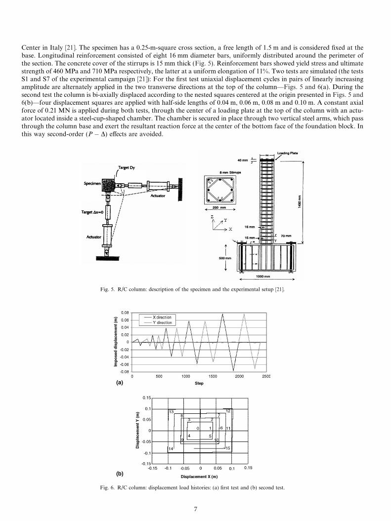
Center in Italy [21]. The specimen has a 0.25-m-square cross section, a free length of 1.5 m and is considered fixed at thebase. Longitudinal reinforcement consisted of eight 16 mm diameter bars, uniformly distributed around the perimeter ofthe section. The concrete cover of the stirrups is 15 mm thick (Fig. 5). Reinforcement bars showed yield stress and ultimatestrength of 460 MPa and 710 MPa respectively, the latter at a uniform elongation of 11%. Two tests are simulated (the testsS1 and S7 of the experimental campaign [21]): For the first test uniaxial displacement cycles in pairs of linearly increasingamplitude are alternately applied in the two transverse directions at the top of the column—Figs. 5 and 6(a). During thesecond test the column is bi-axially displaced according to the nested squares centered at the origin presented in Figs. 5 and6(b)—four displacement squares are applied with half-side lengths of 0.04 m, 0.06 m, 0.08 m and 0.10 m. A constant axialforce of 0.21 MN is applied during both tests, through the center of a loading plate at the top of the column with an actu-ator located inside a steel-cup-shaped chamber. The chamber is secured in place through two vertical steel arms, which passthrough the column base and exert the resultant reaction force at the center of the bottom face of the foundation block. Inthis way second-order (P � D) effects are avoided.
Fig. 5. R/C column: description of the specimen and the experimental setup [21].
Fig. 6. R/C column: displacement load histories: (a) first test and (b) second test.
7

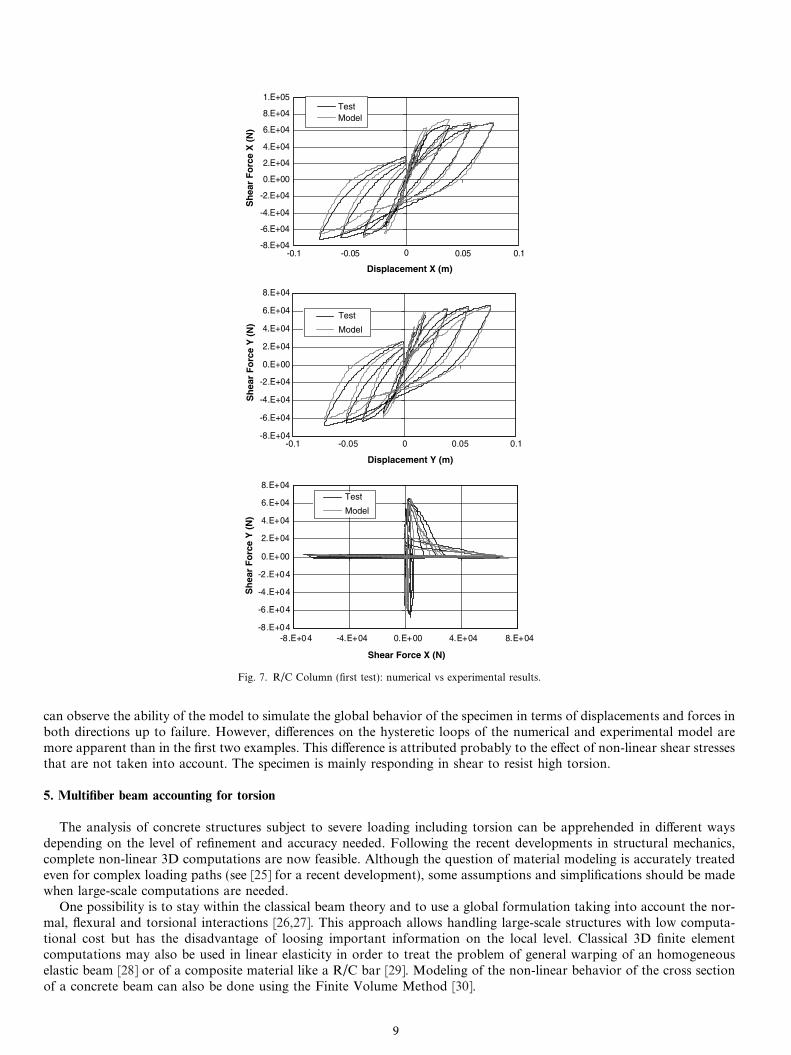
Ten multifiber Timoshenko beam elements having 2 Gauss points are used to model the column. Each section has 36fibers for concrete and 8 fibers for steel. Base slab is not simulated and the specimen is considered fixed at the base. 1Dconstitutive laws are adopted for concrete and steel based on damage mechanics and plasticity respectively (shear and tor-sion are considered linear) [10]. Confinement effects are not considered. In order to resolve the non-linear equations theiterative implicit Newton–Raphson solution procedure is followed, where the secant stiffness matrix is used insuring con-vergence in most cases. This choice leads to a linear rate of convergence instead of the quadratic rate of the classical New-ton–Raphson scheme [22], but is usually the choice when using constitutive laws based on damage mechanics [23]. Specificvalues for the materials are presented in Tables 1 and 2. Comparison of the numerical and experimental results for the eightlevels of loading is represented in Figs. 7 and 8. The model simulates correctly the global behavior of the mock-up in termsof displacements and forces in both directions. Calculation is not time consuming (less than one hour with a modern com-puter) and allows for parametrical studies.
In order to evaluate the effectiveness of the proposed beam element, a second analysis of the S7 test using a coarser meshis presented in Fig. 9. The number of fibers in the section is again equal to 36. Results are quite similar to the ones using adense mesh and the hysteretic cycles are well reproduced.
4.2. U-shaped wall submitted to cyclic loading
The second example concerns the experimental results of a R/C U-shaped wall tested at the reaction wall of the ELSAlaboratory at JRC Ispra [24]. The 3.6 m height—1.0 scaled—specimen is composed of the U-shaped wall, a lower slab andan upper slab and its design follows Eurocode 8 provisions (Fig. 10). The upper slab is used as the horizontal load appli-cation point while six vertical post-tensioning bars apply a normal force of 2 MN. These bars are disposed in such a waythat the force is applied close to the inertial center in order to avoid spurious bending on the structure. Torsional rotation isprohibited during the tests inducing important shear stresses in the specimen. The wall is loaded in both directions accord-ing to ‘‘the butterfly path’’ presented in Fig. 10.
Eleven multifiber Timoshenko beam elements are used for the numerical simulation of the U-shaped wall. 177 fiberssimulate the concrete and 46 fibers the steel. Two Gauss points are considered at each element. Base slab is not simulatedand the wall is considered fixed at the base. The behavior of the top slab is considered linear elastic and rotation of theupper part is prohibited in order to reproduce correctly the boundary conditions of the test. The uniaxial version of theLa Borderie damage constitutive law is used for concrete (shear and torsion are considered linear). In order to take intoaccount the influence of the stirrups the compression strength of the confined concrete is increased up to 30 MPa. Theproperties of the materials used for the calculations are presented in Tables 3 and 4.
Comparison of numerical and experimental results for the eight steps of loading is represented in Fig. 11 (A, B, C lettersrefer to Fig. 10). Again the secant Newton–Raphson scheme is used and the calculation takes only a couple of hours. One
Table 2R/C column: material parameters for steel
Steel
Young�s modulus (steel) 200000 MPaYield strength 460 MPaUltimate strength 710 MPaUltimate deformation 11%
Table 1R/C column: material parameters for concrete
La Borderie damage model
Young�s modulus 20000 MPaPoisson coefficient 0.2A1 6000 MPa�1
A2 5 MPa�1
B1 1B2 1.6b1 1 MPab2 �40 MPaY01 3.8 · 10�4 MPaY02 9 · 10�2 MParf 3.5 MPa
8
-8.E+04
-6.E+04
-4.E+04
-2.E+04
0.E+00
2.E+04
4.E+04
6.E+04
8.E+04
1.E+05
-0.1 -0.05 0 0.05 0.1
Displacement X (m)
Displacement Y (m)
Sh
ear
Fo
rce
X (
N)
TestModel
Test
Model
Test
Model
-8.E+04
-6.E+04
-4.E+04
-2.E+04
0.E+00
2.E+04
4.E+04
6.E+04
8.E+04
-0.1 -0.05 0 0.05 0.1
Sh
ear
Fo
rce
Y (
N)
-8 .E+04
-6 .E+04
-4 .E+04
-2 .E+04
0.E+00
2.E+04
4.E+04
6.E+04
8.E+04
-8.E+04 -4.E+04 0.E+00 4.E+04 8.E+04
Shear Force X (N)
Sh
ear
Fo
rce
Y (
N)
Fig. 7. R/C Column (first test): numerical vs experimental results.
can observe the ability of the model to simulate the global behavior of the specimen in terms of displacements and forces inboth directions up to failure. However, differences on the hysteretic loops of the numerical and experimental model aremore apparent than in the first two examples. This difference is attributed probably to the effect of non-linear shear stressesthat are not taken into account. The specimen is mainly responding in shear to resist high torsion.
5. Multifiber beam accounting for torsion
The analysis of concrete structures subject to severe loading including torsion can be apprehended in different waysdepending on the level of refinement and accuracy needed. Following the recent developments in structural mechanics,complete non-linear 3D computations are now feasible. Although the question of material modeling is accurately treatedeven for complex loading paths (see [25] for a recent development), some assumptions and simplifications should be madewhen large-scale computations are needed.
One possibility is to stay within the classical beam theory and to use a global formulation taking into account the nor-mal, flexural and torsional interactions [26,27]. This approach allows handling large-scale structures with low computa-tional cost but has the disadvantage of loosing important information on the local level. Classical 3D finite elementcomputations may also be used in linear elasticity in order to treat the problem of general warping of an homogeneouselastic beam [28] or of a composite material like a R/C bar [29]. Modeling of the non-linear behavior of the cross sectionof a concrete beam can also be done using the Finite Volume Method [30].
9

-8.E+04
-6.E+04
-4.E+04
-2.E+04
0.E+00
2.E+04
4.E+04
6.E+04
8.E+04
Sh
ear
Fo
rce
Y (
N)
TestModel
-8.E+04
-6.E+04
-4.E+04
-2.E+04
0.E+00
2.E+04
4.E+04
6.E+04
8.E+04
-8.E+04 -4.E+04 0.E+00 4.E+04 8.E+04
Sh
ear
Fo
rce
Y (
N)
TestModel
-8.E+04
-6.E+04
-4.E+04
-2.E+04
0.E+00
2.E+04
4.E+04
6.E+04
8.E+04
-0.15 -0.1 -0.05 0 0.05 0.1 0.15
Displacement X (m)
-0.15 -0.1 -0.05 0 0.05 0.1 0.15
Displacement Y (m)
Shear Force X (N)
Sh
ear
Fo
rce
X (
N)
TestModel
Fig. 8. R/C Column (second test): numerical vs experimental results.
In order to simulate correctly torsional behavior using multifiber beams, the influence in the crack pattern of the sectionhas to be considered. There are various ways:
• linear: generally used,• globally non-linear: with a non-linear relation connecting torque moment and rotation,• locally non-linear: by using a 3D local behavior on each fiber. This approach is difficult because very few concrete con-
stitutive relations are efficient and robust enough under cyclic or dynamic loading. Moreover, two possibilities appear:with or without section warping. The relevancy of considering complex kinematics of the section and 3D local consti-tutive relationships in the framework of a simplified approach is discussed in the following.
5.1. Linear elastic torsion and warping
The aim of the study is to obtain the strain field due to pure torsion for each fiber by solving the warping problem for asection composed of several materials (for example reinforced concrete). Initially the problem is solved within the linearelastic framework of the free torsion of Saint Venant.
10

Fig. 9. R/C Column (second test): results of the numerical model using different number of Timoshenko multifiber beam elements.
Let us consider a R/C section assuming that there is no discontinuity between steel and concrete. Under the hypothesisof small displacements, the solution of the problem is assumed as
uðx; y; zÞ ¼ a � uðy; zÞ; vðx; y; zÞ ¼ �a � x � z and wðx; y; zÞ ¼ a � x � y; ð34Þ
where u, v, w are the three components of the displacement vectors, (O,x,y,z) is the Cartesian frame reference (Fig. 12),u(y,z) the warping function of the section, a = (h2 � h1)/L,~x is the longitudinal axis of the beam (length L) and h1 and h2
denote the rotation of its two edges. Solution of the problem consists in defining the displacement field ~Uðu; v;wÞ under anexternal load ~Mx that respects the equilibrium equations, the boundary conditions and the constitutive equations (linearelasticity). The classical solution follows as
Duðy; zÞ ¼ 0. ð35Þ
5.2. Numerical implementation [31]
In order to solve this plane problem for a section composed of several materials, a warping-conduction analogy methodis used [32]. The problem of the calculation of the warping function for a section made up of several elastic materials (shearmodulus Gi) is transformed into a problem of 2D conduction in a plate made up of several materials (thermal conductivityki). Indeed, the solution of Laplacian equations is trivial in heat transfer. Thus, if the boundary conditions are known, theproblem can be solved with a usual finite element code.
The notations for the mechanical problem of torsion warping are: u(y,z) is the warping function—homogeneous with adisplacement squared—and Gi the shear modulus of the elastic material i.
For the thermal conduction problem, notations are as follows: T(y,z) is the temperature function, ki is the thermal con-ductivity of the isotropic material i and U(y,z) = kgradT(y,z) the thermal density flux.
For torsion one obtains Du(y,z) = 0 in the surface of each material. This equation corresponds to the equation of heatfor conduction in steady state DT(y,z) = 0. The shear modulus of the elastic material Gi is equivalent to ki, the thermalconductivity of the isotropic material.
In order to find the boundary conditions on external contour for torsion, one writes that there are no external forcesapplied to the contour of the section (external surface of the beam), with n, the unit vector leaving normal to contourdS, of component ny and nz. Continuity between two materials is expressed by insuring continuity of the functionu(y,z) and continuity of the forces on the border between two materials.
The conduction problem equivalent to the torsion warping function problem is as follows:
DT ðy; zÞ ¼ 0. ð36Þ
11
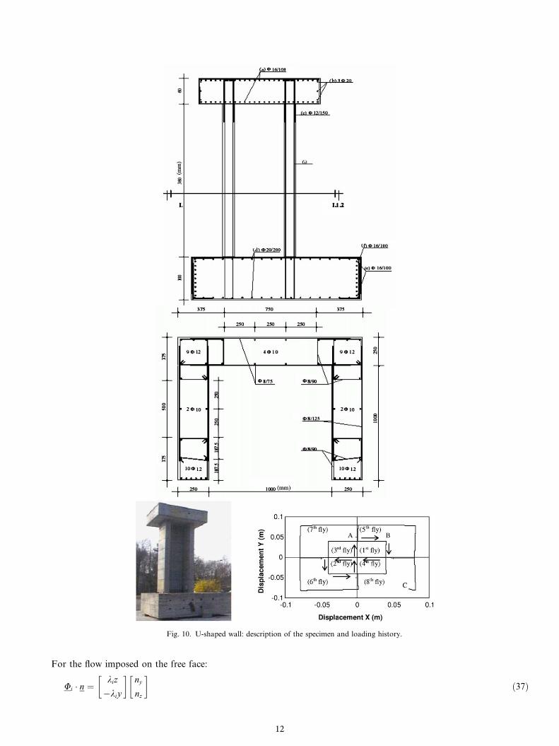
Fig. 10. U-shaped wall: description of the specimen and loading history.
For the flow imposed on the free face:
Ui � n ¼kiz
�kiy
� �ny
nz
� �ð37Þ
12

Table 3U-shaped wall: material parameters for concrete
La Borderie damage model
Young�s modulus 28900 MPaPoisson coefficient 0.25A1 6000 MPa�1
A2 5 MPa�1
A2 (confined) 6.7 MPa�1
B1 1B2 1.6b1 0.4 MPab1 (confined) 1 MPab2 �40 MPaY01 2.3 · 10�4 MPaY02 0.1 · 10�2 MParf 3.5 MPa
Table 4U-shaped wall: material parameters for steel
Steel
Young�s modulus (steel) 200000 MPaYield strength 515 MPaUltimate strength 615 MPaUltimate deformation 24%
-1.2E+06
-8.0E+05
-4.0E+05
0.0E+00
4.0E+05
8.0E+05
1.2E+06
-0.09 -0.06 -0.03 0 0.03 0.06 0.09
Displacement X (m)
Sh
ear
Fo
rce
X (
N)
Test
Model
-8.0E+ 05
-4.0E+ 05
0.0E+00
4.0E+05
8.0E+05
-0.09 -0.06 -0.03 0 0.03 0.06 0.09
Displacement Y (m)
Sh
ear
Fo
rce
Y (
N) Test
Model
C
B
A
A
CB
Fig. 11. U-shaped wall: numerical vs experimental results.
x
y
z
θ2θ1
L
2a
2b
Fig. 12. Beam model in torsion.
and ‘‘jump’’ of flow imposed between two materials:
ðUi � UjÞ � ni ¼ðki � kjÞzð�ki þ kjÞy
� �ni
y
niz
� �. ð38Þ
Thus, by applying these boundary conditions, the problem can be solved with any finite element code able to solve ther-mal conduction problems (the following computations are made using the finite element code CASTEM 2000).
13

This warping function calculation method is used to determine the torsion shear strains all over a beam section:
e ¼
01
2a
ouoy� z
� �1
2a
ouozþ y
� �
1
2a
ouoy� z
� �0 0
1
2a
ouozþ y
� �0 0
266666664
377777775
. ð39Þ
As in [28], the torque moment is obtained by integrating the stresses at the elastic torsion center:
Mx ¼Z
Sðyrxz � zrxyÞdS. ð40Þ
The multifiber framework is a natural integration domain allowing an easy numerical implementation of this approachinto any general-purpose finite element code.
5.3. Non-linear extension
The crack pattern initiated by torsion is assumed to remain constant during crack propagation after nucleation. Thestrain field along the cross section due to torsion and warping may initiate the non-linear behavior but the global shapeof the crack pattern is not be affected by local damage. The warping function is thus computed on the basis of a linearelastic material and is kept constant during the non-linear range.
6. Application
6.1. Torsion of plain concrete beams
The experimental studies used hereafter are from [33]. Several plain concrete beams have been tested in pure torsion. Thebeams are composed of three parts: two reinforced end parts (properly reinforced, so as to remain elastic) and one plainconcrete part in the middle (where cracking and failure occurred during the tests). A pure torsion loading is applied at bothends of the beams (Fig. 13). The beams are supported on two roller supports 1.30 apart, ensuring that the beam is free totwist and to elongate longitudinally. Two types of sections are investigated: a rectangular section specimen (R test) and aT-section specimen (T test) (Fig. 14).
Calculations of the warping functions are carried out for the two specimens. Non-linear calculations of the concrete sec-tions in pure torsion are also presented. It is thus possible to compute the stresses using the local scalar damage constitutiverelation [9]. The parameters used for the materials are fixed from the experimental compression and tension tests results of theR test. However, as the Young�s modulus was unknown it is taken equal to 25000 MPa allowing reproducing the experimen-tal initial stiffness and m, the Poisson ratio, equal to 0.2. The material parameters used for the computation are given in Table 5.
50cm 50cm60cm
Plain concrete
Fig. 13. Plain concrete beam under pure torsion.
10cm
20cm
20cm
10cm 5cm
5cm
Fig. 14. T and rectangular cross sections.
14

Table 5Plain concrete beam: material parameters for concrete
Mazars damage model
Young�s modulus 25000 MPaPoisson coefficient 0.2Initial threshold ed0 1 · 10�04
ACompression 1.4BCompression 1900Atension 0.8Btension 17000Shear correction b 1.06
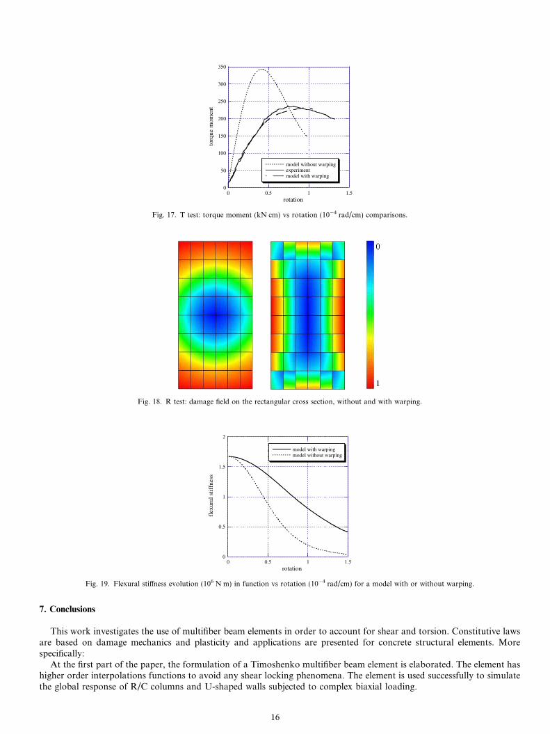
The calculated warping functions for both sections are presented in Fig. 15. In order to highlight the importance of thewarping function for the initial stiffness but also in the non-linear range, two types of analysis have been carried out: eitherby taking into account the warping function, or by neglecting it (i.e. by giving it a zero value all over the sections). For bothsections, the curves giving the evolution of the torque moments (by integrating the stresses upon the section) with the rota-tion angle are plotted in Figs. 16 and 17. Those results show the importance of considering the warping function in order toreproduce correctly the experimental results. The model without the warping function has an initial elastic stiffness higherthan the model considering warping. The maximum torque moment is also poorly evaluated. This can be explained by thefact that the warping function modifies a lot the strain distribution in the section before crack initiation, and thus the dam-age in the section, as shown in Fig. 18. Even though the estimation of the cross section shear strain field using warping isnecessary to describe correctly the maximum bearing capacity of a reinforced concrete member under torsional loading, thebasic assumption made in computing this warping function (constant) seems to be adequate.
The damage patterns in Fig. 18 show that the pattern without warping is similar to the one of a circular section (whereno warping occurs—damage is almost zero near the center of the section) and completely different from the one consideringwarping. This has a crucial consequence on the bending behavior of a beam subjected to both torsion and bending. InFig. 19, the evolution of its bending stiffness is studied, while applying a pure torsion loading and using two types of model:with and without warping. At crack initiation, both models give the same response in terms of stiffness. While cracks prop-agate in the cross section, the two different damage profiles induce a completely different behavior for bending.
Work is in progress in order to apply the proposed modeling strategy to a R/C section.
0
50
100
150
200
250
0 0.2 0.4 0.6 0.8 1
model without warpingexperimentmodel with warping
torq
ue m
omen
t
rotation
Fig. 16. R test: torque moment (kN cm) vs rotation (10�4 rad/cm) comparisons.
Fig. 15. Warping function obtained for the rectangular and T-cross sections.
15
0
50
100
150
200
250
300
350
0 0.5 1 1.5
model without warpingexperimentmodel with warping
torq
ue m
omen
t
rotation
Fig. 17. T test: torque moment (kN cm) vs rotation (10�4 rad/cm) comparisons.
Fig. 18. R test: damage field on the rectangular cross section, without and with warping.
0
0.5
1
1.5
2
0 0.5 1 1.5
model with warpingmodel without warping
flex
ural
stif
fnes
s
rotation
Fig. 19. Flexural stiffness evolution (106 N m) in function vs rotation (10�4 rad/cm) for a model with or without warping.
7. Conclusions
This work investigates the use of multifiber beam elements in order to account for shear and torsion. Constitutive lawsare based on damage mechanics and plasticity and applications are presented for concrete structural elements. Morespecifically:
At the first part of the paper, the formulation of a Timoshenko multifiber beam element is elaborated. The element hashigher order interpolations functions to avoid any shear locking phenomena. The element is used successfully to simulatethe global response of R/C columns and U-shaped walls subjected to complex biaxial loading.
16

For those simulations, shear stresses are considered linear and torsion and shear are uncoupled. However, the formu-lation of the Timoshenko element is presented in a general way and so the element is ready to be used, without any furtherdevelopment, with models able to couple shear and torsion. The implementation of a 3D robust constitutive model forconcrete under cyclic loading would certainly improve the results at the global but also at the local level.
It is necessary though to mention the fact that the behavior of R/C sections under shear (or torsion) is a result of theanisotropic response of the R/C section with cracks developed at a certain inclination with respect to the section�s plane.The use of isotropic damage models and Timoshenko kinematics (where shear stresses are considered constant in the sec-tion) limits the domain of application of the proposed strategy to a slenderness more or less close to 1. This is for exampleshown for the case of R/C concrete walls having very small slenderness (equal to 0.4) in [34]. A solution—always within thefamily of simplified models—is to use some type of truss-analogy models that transfer forces to the longitudinal and trans-verse reinforcements (Strut-and-Tie models [35], the Compression Field Theory [36], the Rotating-Angle-Softened Trussmodel [37], the Equivalent Reinforced Concrete [12,34,38]). The reader can find a detailed presentation of some truss-anal-ogy models in [39].
Furthermore, it is now well known that the use of local constitutive relationships provides results that are mesh-depen-dent in the post-cracking regime. Localized failure is caused by strain softening, which cannot be described by classicalmodels, because they lack a length scale. The use of a non-local damage model [40] or a local strain-gradient model[41,42] can provide a remedy in this particular problem.
At the second part of the paper it is shown that for a non-linear analysis with multifiber beams subject to torsion, theintroduction of warping is crucial in order to reproduce the torque—rotation evolution. Damage profiles are completelydifferent depending on considering or not warping and consequently the global behavior is modified: torsion and bendingstiffness, maximum torque, etc. In this paper the assumption made is that the warping function is constant, determined onelastic assumptions even during crack propagation. The model gives good results for rectangular sections as well as for T-sections in accordance with the experimental results. The next step will be to test the proposed strategy for R/C sectionsunder cyclic loading.
Acknowledgements
The authors would like to thank Pr. Boussias S. from the University of Patras and Pr. Karayannis C.G. from theDemocritus University of Thrace (Greece) for providing the experimental results. Part of this work was granted fromthe European program ICONS [43].
References
[1] T. Paulay, Capacity design of reinforced concrete ductile frames, in: Proceedings, Workshop on Earthquake-Resistant Reinforced Concrete BuildingConstruction, University of California at Berkeley, III, 1970, pp. 1043–1075.
[2] T. Paulay, M.J.N. Priestley, Seismic Design of Reinforced Concrete and Masonry Buildings, Wiley, John & Sons, Incorporated, 1992.[3] M.J.N. Priestley, Myths and Fallacies in Earthquake Engineering, Revisited. The Mallet Milne Lecture, IUSS Press, 2003.[4] A.K. Chopra, Dynamics of Structures: Theory and Applications to Earthquake Engineering, second ed., Prentice-Hall, 2001.[5] A.S. Elnashai, Advanced inelastic static (pushover) analysis for earthquake applications, J. Struct. Engrg. Mech. 12 (1) (2001) 51–69.[6] P. Fajfar, A nonlinear analysis method for performance-based seismic design, Earthquake Spectra 16 (3) (2000) 573–592.[7] J. Lemaitre, J.L. Chaboche, Mechanics of Solids Material, Cambridge University Press, 1990.[8] P.J. Armstrong, C.O. Frederick, A Mathematical Representation of the Multiaxial Bauschinger Effect, G.E.G.B. Report RD/B/N 731, 1966.[9] J. Mazars, A description of micro- and macroscale damage of concrete structures, J. Engrg. Fracture Mech. 25 (5/6) (1986) 729–737.
[10] Ch. La Borderie, Phenomenes unilateraux dans un materiau endommageable: modelisation et application a l�analyse de structures en beton, Ph.D.thesis, Univ. Paris VI, 1991.
[11] P. Kotronis, Cisaillement dynamique de murs en beton arme, Modeles simplifies 2D et 3D. Ph.D., LMT—Ecole Normale Superieure de Cachan,2000.
[12] P. Kotronis, J. Mazars, Simplified modelling strategies to simulate the dynamic behaviour of R/C walls, J. Earthquake Engrg. 9 (2) (2005) 285–306.[13] P. Kotronis, L. Davenne, J. Mazars, Poutre 3D multifibre Timoshenko pour la modelisation des structures en beton arme soumises a des chargements
severes, Rev. Francaise Genie Civil 8 (2–3) (2004) 329–343.[14] M. Petrangeli, P.E. Pinto, V. Ciampi, Fiber element for cyclic bending and shear of RC structures. I: Theory, J. Engrg. Mech. 125 (9) (1999) 994–1001.[15] E. Spacone, F.C. Filippou, F.F. Taucer, Fiber beam-column model for nonlinear analysis of R/C frames. I: Formulation, Earthquake Engrg. Struct.
Dynam. 25 (7) (1996) 711–725.[16] Z. Friedman, J.B. Kosmatka, An improved two-node Timoshenko beam finite element, Comput. Struct. 47 (3) (1993) 473–481.[17] G.R. Cowper, The shear coefficient in Timoshenko�s beam theory, ASME J. Appl. Mech. 33 (1966) 335–340.[18] J. Guedes, P. Pegon, A. Pinto, A fibre Timoshenko beam element in CASTEM 2000, Special publication Nr. I.94.31, J.R.C., I-21020, Ispra, Italy,
1994.[19] F.C. Filippou, Nonlinear static and dynamic analysis for evaluation of structures, in: 3rd European Conference on Structural Dynamics Eurodyn 96,
Florence, Italy, 1996, pp. 395–402.[20] R.L. Taylor, FEAP: A finite element analysis program, version 7.3 manual, University of California, Berkeley, 2000.
17

[21] S.N. Bousias, G. Verzeletti, M.N. Fardis, E. Guiterrez, Load-path effects in column biaxial bending and axial force, J. Eng. Mech. ASCE 121 (5)(1995) 596–605.
[22] M.A. CrisfieldNonlinear Finite Element Analysis of Solids and Structures, vol. I, John Wiley, Chichester, 1991.[23] J. Mazars, G. Pijaudier-Cabot, Continuum damage theory—application to concrete, ASCE J. Engrg. Mech. 115 (1989) 345–365.[24] P. Pegon, C. Plumier, A. Pinto, J. Molina, P. Gonzalez, P. Tognoli, O. Hubert, U-shaped-wall: description of the experimental set-up, Report, Joint
Research Center (J.R.C.), Ispra, Italy, 2000.[25] V. Kafka, Concrete under complex loading: mesomechanical model of deformation and of cumulative damage, Eur. J. Mech. A/Solids 23 (2004) 63–
75.[26] G.H. Powell, P.F. Chen, 3-D beam-column element with generalized plastic hinges, J. Engrg. Mech. Div. ASCE 112 (7) (1986) 627–641.[27] W.A. Thanoon, D.K. Paul, M.S. Jaafar, D.N. Trikha, Influence of torsion on the inelastic response of tree-dimensional r.c. frames, Finite Element
Anal. Des. 40 (2004) 611–628.[28] M. Schulz, F.C. Filippou, Generalized warping torsion formulation, J. Engrg. Mech. (1998) 339–347.[29] Z. Li, J.M. Ko, Y.Q. Ni, Torsional rigidity of reinforced concrete bars with arbitrary sectional shape, Finite Element Anal. Des. 35 (2000) 349–361.[30] C.G. Karayanis, Torsional analysis of flanged concrete elements with tension softening, Comput. Struct. 54 (1) (1995) 97–110.[31] G. Casaux, Modelisation tridimensionnelle du comportement sismique d�ouvrages en beton arme—Developpement de methodes simplifiees, Ph.D.
thesis LMT- Ecole Normale Superieure de Cachan, 2003.[32] J.M. Proix, N. Laurent, P. Hemon, G. Bertrand, Code Aster, manuel de reference, Fascicule R3.08: Elements mecaniques a fibre moyenne,
Document: R3.08.03, Calcul des caracteristiques d�une poutre de section transversale quelconque, 2000.[33] C.G. Karayannis, C.E. Chalioris, Experimental validation of smeared analysis for plain concrete in torsion, J. Struct. Engrg. 126 (6) (2000) 646–653.[34] J. Mazars, P. Kotronis, L. Davenne, A new modelling strategy for the behaviour of shear walls under dynamic loading, Earthquake Engrg. Struct.
Dynam. 31 (4) (2002) 937–954.[35] J. Schlaich, I. Schafer, M. Jennewein, Towards a consistent design of structural concrete, J. Prestress. Concr. Inst. 32 (3) (1987) 74–150.[36] M.P. Collins, D. Mitchell, Shear and torsion design of prestressed and non-prestressed concrete beams, J. Prestress. Concr. Inst. 25 (5) (1980) 32–100.[37] T.T.C. Hsu, Toward a unified nomenclature for reinforced concrete theory, J. Struct. Engrg. ASCE 122 (3) (1996) 275–283.[38] P. Kotronis, J. Mazars, L. Davenne, The equivalent reinforced concrete model for simulating the behaviour of shear walls under dynamic loading,
Engrg. Fracture Mech. 70 (7–8) (2003) 1085–1097.[39] ASCE-ACI Committee 445 on Shear and Torsion, Recent approaches to shear design of structural concrete, J. Struct. Engrg. 124 (12) (1998) 1375–
1417.[40] G. Pijaudier-Cabot, Z.P. Bazant, Nonlocal damage theory, J. Engrg. Mech. 113 (1987) 1512–1533.[41] R. Chambon, D. Caillerie, T. Matsushima, Plastic continuum with microstructure, local second gradient theories for geomaterials: localization
studies, Int. J. Solids Struct. 38 (2001) 8503–8527.[42] P. Kotronis, R. Chambon, J. Mazars, F. Collin, Local second gradient models and damage mechanics: application to concrete, in: 11th International
Conference on Fracture, Turin, Italy, 20–25 March, Org. ICF, cd paper no 5712, 2005.[43] J.M. Reynouard, M.N. Fardis (Eds.), R.T. Severn, R. Bairrao (Gen. Eds.), CAFEEL-ECOEST/ICONS, Thematic report N.5, Shear Walls
Structures, (LNEC, ISBN 972-49-1891-2) September, 2001.
18