using language to gain control of enterprise architecture · what the owner actually has in mind...
TRANSCRIPT
Using Language to Gain Control of Enterprise Architecture
Gary F. Simons, Leon A. Kappelman, & John A. Zachman
Gary F. Simons, Ph.D.
Chief Research Officer
SIL International
7500 W. Camp Wisdom Rd. Dallas, TX 75236
Leon A. Kappelman, Ph.D. (CONTACT AUTHOR)
Professor of Information Systems Director Emeritus, IS Research Center
Founding chair, SIM Enterprise Architecture Working Group
College of Business, University of North Texas
1155 Union Circle #305249, Denton, Texas 76203-5017
John A. Zachman
Zachman International
15954 Jackson Creek Pkwy, Ste B463
Monument, CO 80132 U.S.A.
An earlier version of this manuscript appears in The SIM Guide to Enterprise Architecture, Leon A.
Kappelman, editor, CRC Press, NY, NY 2010
Using Language to Gain Control of Enterprise Architecture On the Verge of Major Business Re-Engineering
Gary F. Simons, Leon A. Kappelman, & John A. Zachman
“Insanity is doing the same thing over and over again and expecting different results.” — Albert Einstein
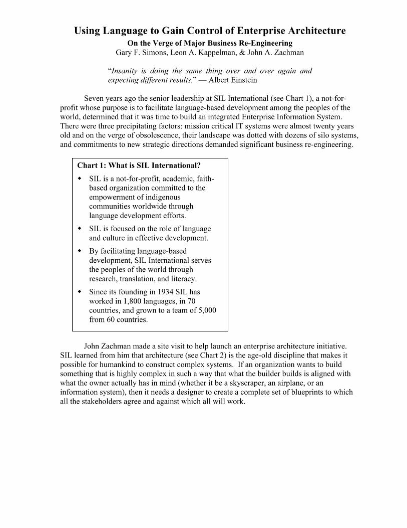
Seven years ago the senior leadership at SIL International (see Chart 1), a not-for-profit whose purpose is to facilitate language-based development among the peoples of the world, determined that it was time to build an integrated Enterprise Information System. There were three precipitating factors: mission critical IT systems were almost twenty years old and on the verge of obsolescence, their landscape was dotted with dozens of silo systems, and commitments to new strategic directions demanded significant business re-engineering.
John Zachman made a site visit to help launch an enterprise architecture initiative. SIL learned from him that architecture (see Chart 2) is the age-old discipline that makes it possible for humankind to construct complex systems. If an organization wants to build something that is highly complex in such a way that what the builder builds is aligned with what the owner actually has in mind (whether it be a skyscraper, an airplane, or an information system), then it needs a designer to create a complete set of blueprints to which all the stakeholders agree and against which all will work.
Chart 1: What is SIL International?
! SIL is a not-for-profit, academic, faith-based organization committed to the empowerment of indigenous communities worldwide through language development efforts.
! SIL is focused on the role of language and culture in effective development.
! By facilitating language-based development, SIL International serves the peoples of the world through research, translation, and literacy.
! Since its founding in 1934 SIL has worked in 1,800 languages, in 70 countries, and grown to a team of 5,000 from 60 countries.

Perhaps even more important in this age of increasingly rapid change is that
architecture is the discipline that makes it possible for an organization to maintain a highly complex system once it is operational. Before the functioning building or airplane or information system can safely, efficiently, and effectively be changed, it is necessary for the owner, designer, and builder to first make the changes on the blueprints and come to agreement that the proposed changes will achieve what the owner wants and can be implemented by the builder.
Nothing So Practical As Good Theory
“In the case of information and communication technologies … investments in associated intangible capital … are quite important indeed.” — Federal Reserve Chairman Ben Bernanke (MIT commencement, June 2006)
The Zachman Framework for Enterprise Architecture (see Chart 3 and Figure 1)
seemed to offer a good theory for what the blueprints of an enterprise should look like: primitive models (see Chart 4) in each of the cells formed by the intersection of rows for stakeholder perspectives (e.g., owner, designer, builder) with columns for interrogative abstractions (i.e., what, how, where, who, when, why).
As the SIL leadership set out to re-engineer the organization, they were inspired by
Zachman’s vision of an enterprise under control through a complete set of aligned blueprints. In an application of social psychologist Kurt Lewin’s famous maxim, “There is nothing so practical as a good theory,” they saw the practical value of the Zachman Framework and
Chart 2: What is Architecture? Architecture is the set of descriptive
representations that are required in order to create an object. Architecture is also the baseline for changing the object once it is created, IF you retain the descriptive representations used in its creation and IF you ensure that the descriptive representations are always maintained consistent with the created object (i.e., the instantiation). The Roman Coliseum is not architecture, it is the result of architecture, an implementation.
If the object you are trying to create is so simple that you can see it at a glance in its entirety and remember all at one time how all of its components fit together at excruciating levels of detail, you don’t need architecture. You can “wing it” and see if it works. It is only when the object you are trying to create is complex to the extent that you can’t see and remember all the details of the implementation at once, and only when you want to accommodate on-going change to the instantiated object, that architecture is imperative.
(Zachman 1987, 2001, 2007)

adopted it as their working theory. Conversely, there is nothing so good for the development of theory as good application in practice, and Zachman with his associate Stan Locke entered into a relationship with SIL to help SIL put theory into practice while SIL helped them refine theory through practice. Following Kotter’s i eight-stage process for managing major change, SIL formed a VP-level guidance team chaired by the Associate Executive Director for Administration. Trained and advised by Locke, this team has met regularly since 2000 to guide the process of architecting a re-engineered enterprise.
Chart 3: What is the Framework for Enterprise Architecture? The Framework for Enterprise Architecture (the “Zachman Framework”, see Figure 1)
is simply a schema, a classification scheme for descriptive representations of objects with enterprise names on the descriptions. It is represented in two dimensions as a table or matrix consisting of six columns and five rows. The schema is “normalized” so that no one fact can show up in more than one cell.
The columns (nicknamed “one” through “six” from left to right) answer the six
interrogatives — what, how, where, who, when, and why, respectively — and correspond to the universal set of descriptive representations for describing any and all complex industrial products (industry-specific variations in terminology notwithstanding): Bills of Materials, Functional Specifications, Drawings, Operating Instructions, Timing Diagrams, and Design Objectives. These are termed “abstractions” in the sense that out of the total set of relevant descriptive characteristics of the object, we “abstract” one of them at a time for producing a formal, explicit, description.
The rows (nicknamed from top to bottom “one” through “five”) represent the set of
descriptions labeled “perspectives” in the sense that each abstraction is created for different audiences: visionaries or planners, executives or owners, architects or designers, engineers or builders, and implementers or sub-contractors respectively. Each of the six abstractions has five different manifestations depending upon the perspective of the intended audience for whom it is created. These are the industrial product equivalents of Scoping Boundaries (“Concepts Package”), Requirements, Schematics (Engineering descriptions), Blueprints (Manufacturing Engineering descriptions), and Tooling configurations; and these correspond to the enterprise equivalents of boundary or scope, business model, logical model, physical or technology model, and tooling configurations.
Enterprise Architecture is the total set of intersections between the abstractions and
the perspectives that constitutes the total set of descriptive representations relevant for describing an enterprise: And the ENTERPRISE itself is the implementation, the instantiation, the end result of doing Enterprise Architecture, and is depicted in the framework as row six.
(Zachman 1987, 2001, 2007; Zachman & Sowa 1992)

Architecture Out of Control “The problem with communication ... is the illusion that it has been accomplished.” — George Bernard Shaw
SIL enjoyed excellent buy-in and participation by senior leadership and IT staff, and found that Zachman’s framework was a powerful tool for helping conceptualize what they were doing. But SIL also found that they lacked the tools to deliver all the blueprints. Only in Zachman’s leftmost column one of the framework (i.e., data) did they succeed in creating formal blueprints. The entity-relationship diagramsii commonly used by database designers are compatible with Zachman’s notion of a primitive thing-relationship-thing model. Thus SIL was able to achieve alignment and control in column one by using a popular entity-relationship modeling tool. But SIL found nothing comparable for the other five columns (process, location, organization, timing, and motivation).
Figure 1: The Zachman Framework for Enterprise Architecture
e.g. DATA
ENTERPRISE ARCHITECTURE - A FRAMEWORK
Builder
SCOPE(CONTEXTUAL)
MODEL(CONCEPTUAL)
ENTERPRISE
Designer
SYSTEMMODEL(LOGICAL)
TECHNOLOGYMODEL(PHYSICAL)
DETAILEDREPRESEN- TATIONS(OUT-OF- CONTEXT)
Sub-Contractor
FUNCTIONINGENTERPRISE
DATA FUNCTION NETWORK
e.g. Data Definition
Ent = FieldReln = Address
e.g. Physical Data Model
Ent = Segment/Table/etc.Reln = Pointer/Key/etc.
e.g. Logical Data Model
Ent = Data EntityReln = Data Relationship
e.g. Semantic Model
Ent = Business EntityReln = Business Relationship
List of Things Importantto the Business
ENTITY = Class ofBusiness Thing
List of Processes theBusiness Performs
Function = Class ofBusiness Process
e.g. Application Architecture
I/O = User ViewsProc .= Application Function
e.g. System Design
I/O = Data Elements/SetsProc.= Computer Function
e.g. Program
I/O = Control BlockProc.= Language Stmt
e.g. FUNCTION
e.g. Business Process Model
Proc. = Business ProcessI/O = Business Resources
List of Locations in which the Business Operates
Node = Major BusinessLocation
e.g. Business Logistics System
Node = Business LocationLink = Business Linkage
e.g. Distributed System
Node = I/S Function(Processor, Storage, etc)Link = Line Characteristics
e.g. Technology Architecture
Node = Hardware/SystemSoftware
Link = Line Specifications
e.g. Network Architecture
Node = AddressesLink = Protocols
e.g. NETWORK
Architecture
Planner
Owner
Builder
ENTERPRISEMODEL
(CONCEPTUAL)
Designer
SYSTEMMODEL
(LOGICAL)
TECHNOLOGYMODEL
(PHYSICAL)
DETAILEDREPRESEN-
TATIONS (OUT-OF
CONTEXT)
Sub-Contractor
FUNCTIONING
MOTIVATIONTIMEPEOPLE
e.g. Rule Specification
End = Sub-conditionMeans = Step
e.g. Rule Design
End = ConditionMeans = Action
e.g., Business Rule Model
End = Structural AssertionMeans =Action Assertion
End = Business ObjectiveMeans = Business Strategy
List of Business Goals/Strat
Ends/Means=Major Bus. Goal/Critical Success Factor
List of Events Significant
Time = Major Business Event
e.g. Processing Structure
Cycle = Processing CycleTime = System Event
e.g. Control Structure
Cycle = Component CycleTime = Execute
e.g. Timing Definition
Cycle = Machine CycleTime = Interrupt
e.g. SCHEDULE
e.g. Master Schedule
Time = Business EventCycle = Business Cycle
List of Organizations
People = Major Organizations
e.g. Work Flow Model
People = Organization UnitWork = Work Product
e.g. Human Interface
People = RoleWork = Deliverable
e.g. Presentation Architecture
People = UserWork = Screen Formate.g. Security Architecture
People = IdentityWork = Job
e.g. ORGANIZATION
Planner
Owner
to the BusinessImportant to the Business
What How Where Who When Why
John A. Zachman, Zachman International (810) 231-0531
SCOPE(CONTEXTUAL)
Architecture
e.g. STRATEGYENTERPRISE
e.g. Business Plan
TM
THE ENTERPRISE INSTANTIATION
THE ENTERPRISE ARCHITECTURE

It turns out that existing modeling techniques, although useful for other purposes, were not well suited since they did not produce primitive models for the single normalized cells of Zachman’s framework. Rather, they produced composite models combining elements from multiple rows or columns of the framework. An obvious alternative would be to use a general drawing program to simply draw the models. SIL tried this, but it did not work. Unlike the entity-relationship tool which was inherently compatible with the Zachman metamodel for column one and thus could not generate anything but a compatible model no matter who used it, a general drawing program is unconstrained and cannot guarantee conformity with the framework or consistency between practitioners.
Another advantage of the entity-relationship tool was that it is based on a single
underlying knowledge structure that kept the owner, designer, and builder views of the blueprints in alignment. With the general drawing tool, however, once drawings were created, it was virtually impossible to keep them maintained and aligned. In order to give guidance to system builders, some models were described in documents and spreadsheets rather than diagrams, but these were similarly unconstrained and subject to all the same
Chart 4: Primitive and Composite Models: Why things go bump in the night.
A “primitive” model is a model in one variable— the combination of one abstraction with one perspective — that is an artifact specific to one cell of the Zachman Framework. It is the raw material for doing engineering and architecture.
In contrast, a “composite” model is comprised of
more than one abstraction and/or more than one perspective. Implementations are the instantiation of composite, multi-variable models. Implementations are manufacturing, the creation of the end result. An instantiation, by definition is a composite. An enterprise, an information system, and a computer program are instantiations and therefore composites.
The question turns out to be, how did you create
the implementation instance? Was it engineered (architected) from primitive models or did you simply create the implementation ad hoc (i.e., it was implemented but NOT architected with primitives)? If you are not creating “enterprise-wide” primitives, you risk creating implementations that will not integrate into the enterprise as a whole. You can manufacture parts of the whole iteratively and incrementally; however, they must be engineered to fit together or they are not likely to fit together (be aligned or easily integrated). Enterprise-wide integration and alignment do not happen by accident. They must be engineered (architected).
(Zachman 1987, 2001, 2007)
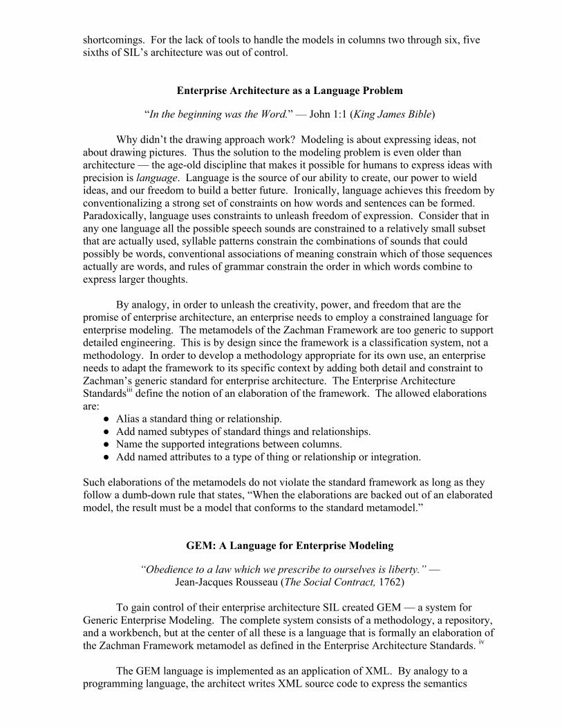
shortcomings. For the lack of tools to handle the models in columns two through six, five sixths of SIL’s architecture was out of control.
Enterprise Architecture as a Language Problem
“In the beginning was the Word.” — John 1:1 (King James Bible)
Why didn’t the drawing approach work? Modeling is about expressing ideas, not about drawing pictures. Thus the solution to the modeling problem is even older than architecture — the age-old discipline that makes it possible for humans to express ideas with precision is language. Language is the source of our ability to create, our power to wield ideas, and our freedom to build a better future. Ironically, language achieves this freedom by conventionalizing a strong set of constraints on how words and sentences can be formed. Paradoxically, language uses constraints to unleash freedom of expression. Consider that in any one language all the possible speech sounds are constrained to a relatively small subset that are actually used, syllable patterns constrain the combinations of sounds that could possibly be words, conventional associations of meaning constrain which of those sequences actually are words, and rules of grammar constrain the order in which words combine to express larger thoughts.
By analogy, in order to unleash the creativity, power, and freedom that are the
promise of enterprise architecture, an enterprise needs to employ a constrained language for enterprise modeling. The metamodels of the Zachman Framework are too generic to support detailed engineering. This is by design since the framework is a classification system, not a methodology. In order to develop a methodology appropriate for its own use, an enterprise needs to adapt the framework to its specific context by adding both detail and constraint to Zachman’s generic standard for enterprise architecture. The Enterprise Architecture Standardsiii define the notion of an elaboration of the framework. The allowed elaborations are:
● Alias a standard thing or relationship. ● Add named subtypes of standard things and relationships. ● Name the supported integrations between columns. ● Add named attributes to a type of thing or relationship or integration.
Such elaborations of the metamodels do not violate the standard framework as long as they follow a dumb-down rule that states, “When the elaborations are backed out of an elaborated model, the result must be a model that conforms to the standard metamodel.”
GEM: A Language for Enterprise Modeling
“Obedience to a law which we prescribe to ourselves is liberty.” — Jean-Jacques Rousseau (The Social Contract, 1762)
To gain control of their enterprise architecture SIL created GEM — a system for
Generic Enterprise Modeling. The complete system consists of a methodology, a repository, and a workbench, but at the center of all these is a language that is formally an elaboration of the Zachman Framework metamodel as defined in the Enterprise Architecture Standards. iv
The GEM language is implemented as an application of XML. By analogy to a
programming language, the architect writes XML source code to express the semantics

(owner view) and logic (designer view) of a system — including things, relationships, integrations, transformations, added detail, and prose definitions. The system compiles the XML source into the graphic primitive models for each cell of the framework. The system also compiles the XML source into “textual models” for each cell — HTML documents that provide human-readable descriptions.
For example, Figure 2 shows a fragment from the owner-level process model (that is,
the intersection of Row Two and Column Two) for the subsystem that maintains and produces Ethnologue: Languages of the World.v The Ethnologue is a 1,272-page reference book published by SIL that catalogs all known languages of the present-day world. Now in its fifteenth edition, the Ethnologue identifies 6,912 living languages, both spoken and signed.
In the GEM language, each type of thing and relationship used in the primitive thing-relationship-thing models has its own XML element. For example, the fragment in Figure 2 illustrates two kinds of things in the owner-level process model, <inventory> representing a process for maintaining an inventory of data entities and <publication> representing a process for producing a publication. These are two kinds of processes that recur in SIL’s enterprise, so Zachman’s generic notion of a Row Two process has been elaborated by defining these two subtypes. Each thing element has an ID attribute, which provides a unique identifier that can be used as the target of relationships. Each thing element also contains a <name> and <description> element for human-readable documentation. The XML element for a relationship is embedded in the thing it originates from and contains an IDREF attribute that expresses the unique identifier of the thing that is the target of the relationship. In Figure 2, <fedBy> is an example of a relationship. The instance <fedBy process=”c2.WorldLang”/> is embedded in the Ethnologue Edition process and points to the World Language Inventory process. It is therefore a formal statement of the fact, “The Ethnologue Edition publication process is fed by the output of the World Language Inventory
Figure 2: An example of GEM language source code
<columnTwo> <businessProcesses> <inventory id=”c2.WorldLang”> <name>World Language Inventory</name> <description>The process that maintains the most up-to-date information about the existence and status of every known language.</description> </inventory> <publication id=”c2.edition”> <name>Ethnologue Edition</name> <description>The process that produces a particular, published edition of the catalog of all known living languages of the world.</description> <fedBy process=”c2.WorldLang”/> <fedBy process=”c2.LangMaps”/> <producedAt location="c3.HQ"/> <timing cycle="c5.Edition"/> </publication> ... </businessProcesses> ... </columnTwo>

process.” Figure 3 shows the graphic representation of this model that is generated by GEM from the source fragment in Figure 2.
Relationships between things in different columns are called integrations and are
expressed in the same way. In Figure 2, <producedAt> integrates the process to the thing in the Column Three model that represents the location where it is produced and <timing> integrates the process to the thing in the Column Five model that represents the timing cycle for the process. Figure 4 shows the textual model generated by GEM for the <publication> element in Figure 2. It is an HTML document in which the targets of the relationships and integrations are active links to the definition of the referenced thing. This example illustrates an important feature of the GEM language, namely, that the reverse relationships and integrations are never expressed explicitly in the XML source code, but always inferred by the compiler that generates the textual model, thus avoiding redundancy and the potential for update anomaly. For instance, in Figure 4, the “Produced by” and “Consumed by” integrations were actually expressed in the source code of the Column Four model and the “Motivation” integration was actually expressed in the source code of the Column Six model.
Figure 5 summarizes the coverage of GEM for modeling the owner (Row Two)
perspective. This represents about one-third of the GEM language; the remainder is for modeling the things, relationships, and integrations of the designer perspective (Row Three), plus further details like attributes of data entities and states of timing cycles that are needed to fully specify the logical design of a subsystem. The rows of the table in Figure 5 correspond to the six columns of the Zachman Framework (labeled C1 through C6). The
Figure 3: The graphic model generated from Figure 2
Figure 4: The textual model generated from Figure 2
Ethnologue Edition A publication process. The process that produces a
particular, published edition of the catalog of all known living languages of the world.
Relationships Fed by: Language Map Inventory Fed by: World Language Inventory
Integrations Produced at: International Headquarters Consumed by: Public Produced by: VP Academic Affairs Office Timing: Ethnologue Edition Cycle Motivation: Publish Ethnologue
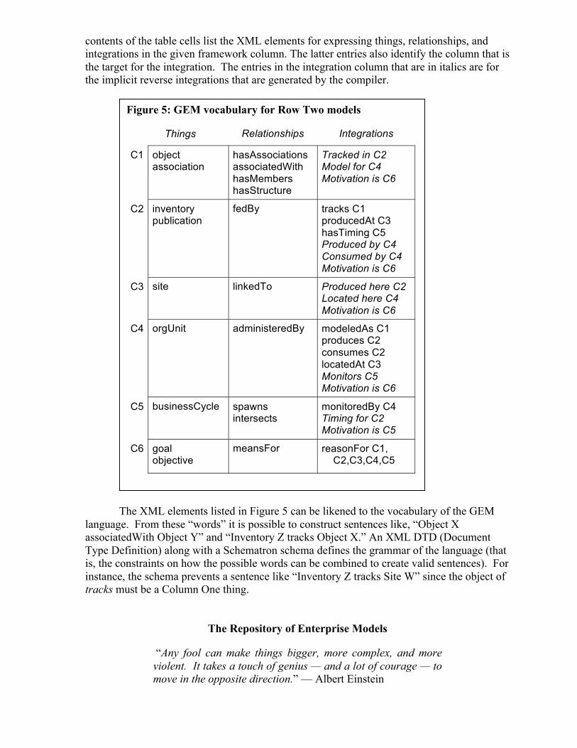
contents of the table cells list the XML elements for expressing things, relationships, and integrations in the given framework column. The latter entries also identify the column that is the target for the integration. The entries in the integration column that are in italics are for the implicit reverse integrations that are generated by the compiler.
The XML elements listed in Figure 5 can be likened to the vocabulary of the GEM
language. From these “words” it is possible to construct sentences like, “Object X associatedWith Object Y” and “Inventory Z tracks Object X.” An XML DTD (Document Type Definition) along with a Schematron schema defines the grammar of the language (that is, the constraints on how the possible words can be combined to create valid sentences). For instance, the schema prevents a sentence like “Inventory Z tracks Site W” since the object of tracks must be a Column One thing.
The Repository of Enterprise Models
“Any fool can make things bigger, more complex, and more violent. It takes a touch of genius — and a lot of courage — to move in the opposite direction.” — Albert Einstein
Figure 5: GEM vocabulary for Row Two models
Things Relationships Integrations
C1 object association
hasAssociations associatedWith hasMembers hasStructure
Tracked in C2 Model for C4 Motivation is C6
C2 inventory publication
fedBy tracks C1 producedAt C3 hasTiming C5 Produced by C4 Consumed by C4 Motivation is C6
C3 site linkedTo Produced here C2 Located here C4 Motivation is C6
C4 orgUnit administeredBy modeledAs C1 produces C2 consumes C2 locatedAt C3 Monitors C5 Motivation is C6
C5 businessCycle spawns intersects
monitoredBy C4 Timing for C2 Motivation is C5
C6 goal objective
meansFor reasonFor C1, C2,C3,C4,C5
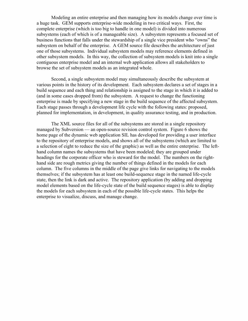
Modeling an entire enterprise and then managing how its models change over time is a huge task. GEM supports enterprise-wide modeling in two critical ways. First, the complete enterprise (which is too big to handle in one model) is divided into numerous subsystems (each of which is of a manageable size). A subsystem represents a focused set of business functions that falls under the stewardship of a single vice president who “owns” the subsystem on behalf of the enterprise. A GEM source file describes the architecture of just one of those subsystems. Individual subsystem models may reference elements defined in other subsystem models. In this way, the collection of subsystem models is knit into a single contiguous enterprise model and an internal web application allows all stakeholders to browse the set of subsystem models as an integrated whole.
Second, a single subsystem model may simultaneously describe the subsystem at
various points in the history of its development. Each subsystem declares a set of stages in a build sequence and each thing and relationship is assigned to the stage in which it is added to (and in some cases dropped from) the subsystem. A request to change the functioning enterprise is made by specifying a new stage in the build sequence of the affected subsystem. Each stage passes through a development life cycle with the following states: proposed, planned for implementation, in development, in quality assurance testing, and in production.
The XML source files for all of the subsystems are stored in a single repository
managed by Subversion — an open-source revision control system. Figure 6 shows the home page of the dynamic web application SIL has developed for providing a user interface to the repository of enterprise models, and shows all of the subsystems (which are limited to a selection of eight to reduce the size of the graphic) as well as the entire enterprise. The left-hand column names the subsystems that have been modeled; they are grouped under headings for the corporate officer who is steward for the model. The numbers on the right-hand side are rough metrics giving the number of things defined in the models for each column. The five columns in the middle of the page give links for navigating to the models themselves; if the subsystem has at least one build-sequence stage in the named life-cycle state, then the link is dark and active. The repository application (by adding and dropping model elements based on the life-cycle state of the build sequence stages) is able to display the models for each subsystem in each of the possible life-cycle states. This helps the enterprise to visualize, discuss, and manage change.

Figure 7 is a screenshot showing the result of clicking on the “Development” state
link for the Ethnologue subsystem that appears in Figure 6. The body of the page contains 35 links, each of which produces a different view of information in the single GEM language source file. The application is built with Apache Cocoon — an open-source web application framework that uses pipelines of XSLT scripts to transform the XML source file on-the-fly into the requested textual and graphic displays. The top half of the screen gives links to displays that summarize the models over all the columns of the Zachman Framework. The bottom half of the screen gives links to the individual cell models for the top three rows of the Zachman Framework. These are the rows that deal with the ideas that lie behind the subsystem before it is transformed into a technology solution. These are the models that are used by executive leaders and the staff sections they manage. This repository application is aimed at these users; another application, the GEM Workbench, is aimed at IT staff and encompasses all the rows of the Zachman Framework.
Figure 6: The GEM Repository of Enterprise Models

Figure 8 shows the first page of the HTML document generated as a result of clicking
the “model” link in Row Two and Column Two. It illustrates the content from Figure 4 in its full context. Each of the eighteen “list” and “model” links in the bottom half of Figure 7 generates a comparable document. The G icons in the second and third rows are also links; they generate the graphic form of the primitive cell model.
Figure 7: Framework for the Ethnologue System in Development State

Figure 9 shows all six of the graphic models generated for Row Two of the
development state of the Ethnologue subsystem. These graphs are created by transforming the XML source model into a graph specification in the DOT graphic description language which is then rendered on-the-fly by Graphviz — an open-source graph visualization package.
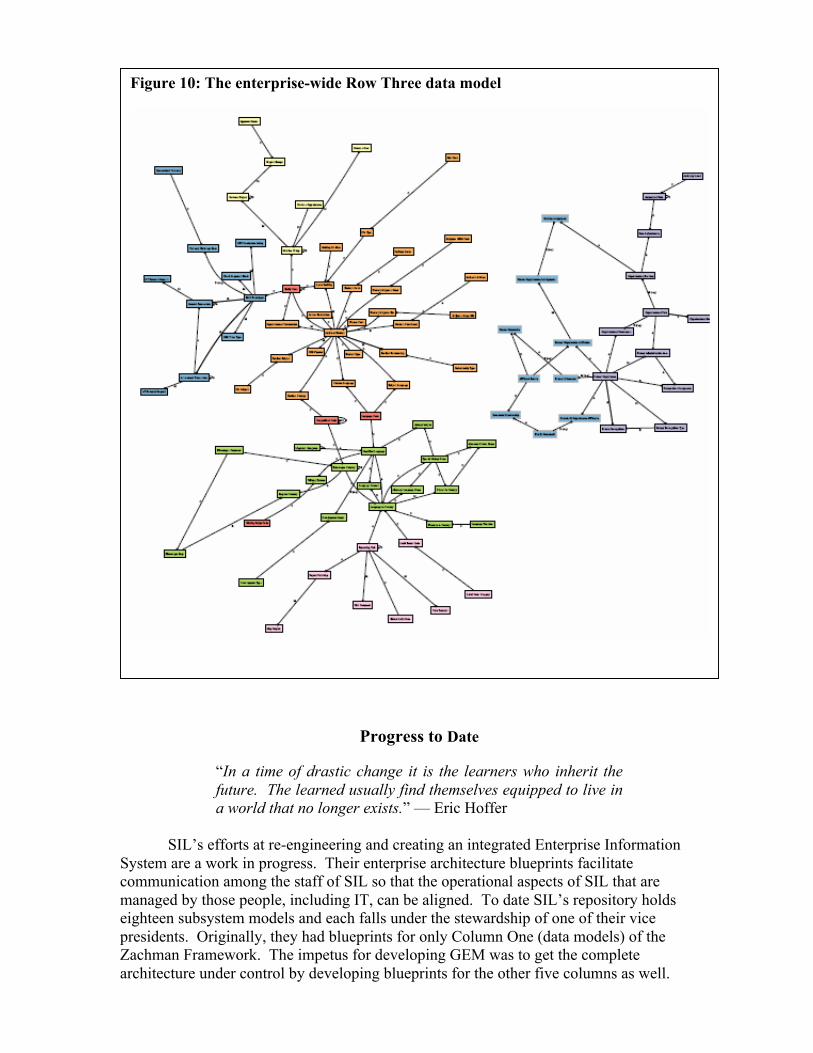
Since the XML source file for one subsystem is able to make reference to an element
defined in another subsystem, the repository application is able to assemble the entire enterprise model by aggregating the individual subsystem models. This is the effect of clicking on the links for Complete Enterprise at the bottom of Figure 6. The result is a screen comparable to Figure 7, but that generates the models for the entire enterprise by aggregating the individual subsystem models. For example, Figure 10 shows the Row Three data model for all the subsystems that are in production — in other words, it is the logical data model for the Enterprise Information System as it is currently in production. The entities are defined in eight different subsystems and the graphic color codes the entities by subsystem. This graph brings to light a current deficiency in the state of development — the six subsystems on the left side of the graph form a contiguous model, but the two subsystems on the right have yet to be integrated with the rest of the enterprise.
Figure 8: A primitive cell model (as text)

Figure 9: All Six Primitive Cell Models for Row Two (as graphs)
Progress to Date
“In a time of drastic change it is the learners who inherit the future. The learned usually find themselves equipped to live in a world that no longer exists.” — Eric Hoffer
SIL’s efforts at re-engineering and creating an integrated Enterprise Information System are a work in progress. Their enterprise architecture blueprints facilitate communication among the staff of SIL so that the operational aspects of SIL that are managed by those people, including IT, can be aligned. To date SIL’s repository holds eighteen subsystem models and each falls under the stewardship of one of their vice presidents. Originally, they had blueprints for only Column One (data models) of the Zachman Framework. The impetus for developing GEM was to get the complete architecture under control by developing blueprints for the other five columns as well.
Figure 10: The enterprise-wide Row Three data model

Figure 11 reports the progress to date in achieving this. This, as well as the entire GEM development effort, represents the work product of a small team consisting of an enterprise architect and a software engineer (both devoting less than half-time to the endeavor), plus a few domain specialists who have learned to do the GEM modeling for subsystems in their domain. The two rows of the table separate counts for the eight subsystems that are now part of the in-production integrated Enterprise Information System versus the ten that are in an earlier stage of planning or development. The second column in the table gives a sense of the size of the effort by reporting the number of data entities in the Column One models. (Note that a large number of the data entities for the subsystems in production are within build-sequence stages that are not yet in production; this is why the aggregated model in Figure 10 contains many fewer than 178 entities.) The remaining columns show the progress toward modeling the enterprise in all columns of the Zachman Framework: three-quarters of the subsystems are now modeled in two columns, just over half in three columns, one-third in five columns, and only one-sixth in all six columns.
Considering that most enterprises today are fortunate to have even the single data
column fully architected, let alone enterprise-wide, SIL stands at the vanguard of what may be a paradigm shift in how enterprises are managed. A change in thought and practice perhaps as significant as those brought about in the Industrial Age by Frederick Taylor’s “scientific management” and Joseph Juran’s “statistical quality control”.vi And with their enterprise architecture language, tools, methods, and process in place, and with significant organizational learning and success already experienced, SIL’s pace and momentum are on the rise.
Lessons Learned
“Someday, you’re going to wish you had all those models, enterprise-wide, horizontally and vertically integrated, at an excruciating level of detail.” — John Zachman
Even more than the benefits of creating new tools, processes, methods, innovations,
technologies, and intellectual capital while transforming their IT systems, SIL has learned some critical and universal lessons. Lessons, perhaps even basic truths, which shed light not only on the practice and value of enterprise architecture but also on some of the fundamental causes of seemingly intractable issues in IT management, such as the perennial quest for alignment.
Among these was the discovery that when the owner speaks directly with the builder
(skipping over the Row Three designer), the result is typically a localized stove-piped
Figure 11: Enterprise Architecture Progress and Control at SIL
GEM subsystems
Data entities
Modeled in at least n columns of the Zachman Framework
2 3 4 5 6 In production 8 178 5 4 3 3 1 Not in production 10 248 9 6 3 3 2
Totals 18 426 14 10 6 6 3 As per cent 78% 56% 33% 33% 17%

solution that is not architecturally optimal and thus difficult and costly to integrate and change. That is, the problem of immediate concern is solved but at the cost of adding more complexity to the overall enterprise than was actually necessary. Regrettably, the lack of staff that can function as Row Three architects has been a bottleneck in most of SIL’s projects, and it appears this shortage of the architecturally skilled is widespread. Row Three is a scarce but critical perspective.
The fact that someone has been successful as a software designer (Row Four) does
not mean they will be successful as an enterprise designer in Row Three. It takes someone who can straddle the owner’s perspective in Row Two and the builder’s perspective in Row Four — who can translate the owner’s view into a formal logical design that transcends any particular technology for implementing it. Technology designers tend to push a Row Four perspective into Row Three by solving the problem in terms of their preferred technology. The GEM language is giving SIL a way to train people to function in the Row Three role without getting drawn into the details of a Row Four technology solution.
Through GEM, SIL has also learned that having and maintaining “all those models”
is possible if they are automatically generated from a single source. When all the primitive models are generated on demand from a single source they always stay synchronized and in alignment, and enable the enterprise as implemented to be in alignment, In sum, SIL has found that elaborating Zachman’s Enterprise Architecture Standards to create a custom modeling language allows an enterprise to gain control of its architecture; but more importantly, to gain control of the actual data, processes, technologies, people, and other resources of which the architecture is a representation. Moreover, having a constrained formal language allows novice modelers to be productive and ensures that all modelers produce comparable results.
But more than all this, SIL has found that the most important result of their enterprise
architecture initiative was not the new Enterprise Information System (as they originally thought it would be), but an enterprise change management process that will make it possible for them to use their newly developed enterprise blueprints to manage the never ending cycle of changes to the enterprise. In other words, enterprise architecture is the key to SIL achieving the design objectives that keep nearly all IT managers up at night — alignment, simplicity, flexibility, speed, and agility.
In order to ensure that this is the result, SIL’s EA leadership team recently assigned
their Chief Architect two new highest priorities: (1) developing a plan for finishing the blueprints of all subsystems that are part of the in-production Enterprise Information System (including reverse engineering the models for the legacy subsystems and third-party systems that were integrated without blueprints), and (2) assisting the EA Program Manager to specify an enterprise change management process that is based on managing the complete blueprints.
Zachman’s theory remains confirmed by the practical experience of SIL International,
and SIL has realized tangible and intangible benefits as their enterprise architecture efforts are helping them to bridge the chasm between strategy and implementationvii. SIL has found that their architecture isn’t their organization any more than a map is the highway or the blueprints the building. But like maps and blueprints, enterprise architecture is a tool to help us efficiently and effectively get where we want to go, and to keep us from getting lost.

References
Chen, Peter P. (1976). “The Entity-Relationship Model: Toward a Unified View of Data,” ACM Transactions on Database Systems, vol. 1, no. 1, pp. 9-36.
Gordon, Raymond G., Jr. (ed.) (2005). Ethnologue: Languages of the World, (15th edn.).
Dallas: SIL International. Web edition at: http://www.ethnologue.com. Kappelman, Leon A. (2007). “Bridging the Chasm,” Architecture and Governance, vol. 3,
no. 2, http://www.architectureandgovernance.com/articles/09-lastword.asp. Kotter, John P. (1996). Leading Change. Harvard Business School Press. Ross, Jeanne (2003), “Creating a Strategic IT Architecture Competency: Learning in Stages,”
MISQ Executive, Volume 2, Issue 1. Zachman, John A. (1987). “A Framework for Information Systems Architecture,” IBM
Systems Journal, vol. 26, no. 3, IBM Publication G321-5298. http://www.zachman.com/resources/ea-articles-reference/49-1987-ibm-systems-journal-a-framework-for-information-systems-architecture
Zachman, John A. (2001). The Zachman Framework for Enterprise Architecture: A Primer for Enterprise Engineering and Manufacturing, Zachman International. (Out of Print)
Zachman, John A. (2006). “Enterprise Architecture Standards.” Zachman International. Zachman, John A. (2007). “Architecture Is Architecture Is Architecture,“ EIMInsight, vol. 1,
no. 1, March, Enterprise Information Management Institute. http://www.zachman.com/resources/ea-articles-reference/52-architecture-is-architecture-is-architecture-by-john-a-zachman
Zachman, John A. and Sowa, J. F. (1992). “Extending and Formalizing the Framework for
Information Systems Architecture,” IBM Systems Journal, vol. 31, no. 3, IBM Publication G321-5488. An earlier version of this manuscript appears in The SIM Guide to Enterprise Architecture, Leon A. Kappelman, editor, CRC Press, NY, NY 2010. http://www.zachman.com/resources/ea-articles-reference/50-1992-ibm-systems-journal-extending-and-formalizing-the-framework-for-information-systems-architecture