using external heat exchangers in biomass boiler systems
TRANSCRIPT

© Copyright 2021, J. Siegenthaler all rights reserved. The contents of this file shall not be copied or transmitted in any form without written permission of the author. All diagrams shown in this file on conceptual and not intended as fully detailed installation drawings. No warranty is made as the the suitability of any drawings or data for a particular application.
John Siegenthaler, P.E.Principal, Appropriate DesignsHolland Patent, NYwww.hydronicpros.com
presented by:
Sponsored by:
March 18, 20211:00 PMModerated by:Sue DoughertyClean Heating & Cooling [email protected]
Using external heat exchangers in biomass boiler systems with non-pressurized thermal storage.
flow switch
stainless steel !heat exchanger
to / from!other loads
HX flushing valves storage tank!(with varying temperature)
hot water
cold water
!mixing valve
electric tankless!water heater
to /
from
hea
t so
urce
(s)
swing check valve
circulator with check valve
circulator with check valve

Session description: Many cordwood gasification systems use unpressurized thermal storage tanks. A common approach is to use coiled copper tube heat exchangers suspended within these tanks. An alternative approach uses external brazed plate stainless steel heat exchangers. This webinar exams the advantages of the latter approach. It also shows how a single external heat exchanger can be used for both heat input to the thermal storage and heat extraction.
Learning objectives:
1. Understand differences between immersed coil and brazed plate heat exchangers.
2. Understand how to pipe brazed plate heat exchanger in combination with non-pressurized thermal storage tanks
3. Explain options for heating domestic water in systems using non-pressurized thermal storage and brazed plate heat exchangers.
4. Describe why counterflow is important for heat exchangers.
Using external heat exchangers in biomass boiler systems with non-pressurized thermal storage.

Design Assistance Manual for High Efficiency Low Emissions Biomass Boiler Systems
https://www.nyserda.ny.gov/-/media/Files/EERP/Renewables/Biomass/Design-Assistance-Biomass-Boiler.pdf
It’s available as a FREE downloadable PDF at:

Unpressurized thermal storage tanks

Unpressurized thermal storage tanksConsiderations:
• Water will evaporate - water level must be monitored• Air space above water accommodates water expansion• Many open tanks are “knock down” construction and are assembled on site• Typically lower cost ($/gallon) than pressurized tanks• Requires one or more heat exchangers to interface with boiler or distribution system• May require water treatment to control biological slime growth (use Fernox)
• Must use stainless steel or bronze circulators to handle open system water
courtesy of Hydroflexcourtesy of American Solartechnics

Open (unpressurized) buffer tanks
images courtesy of Hydroflex

To date, the most common method of adding and removing heat from an unpressurized tank has been to use coil heat exchangers
vent
air space
heat input coil
heat output
coil

Considerations for coil heat exchangers• All liquid-to-liquid heat exchangers involve two surfaces where convection heat transfer between a liquid and solid surface occur.
• In general, the convection coefficients created by “natural convection” along the outer surface of a coil heat exchanger are much lower (<10%) than those created by “forced convection” along the inner surface of the coil (due primarily to fluid velocity).
• The rate of convection depends on the “convection coefficient” between the liquid and the surface.
• Convection coefficients can be very complex to calculate. They depend on liquid velocity, fluid properties, geometry.
q = hA(∆T )where:q= rate of heat transfer (Btu/hr)h = convection coefficient (Btu/hr/ft2/ºF)A = surface area over which heat is moving (ft2)∆T = temperature difference between fluid “bulk” temperature and surface temperature (ºF)
• For a given rate of heat transfer, the surface area associated with natural convection is much larger than that required by forced convection.
vent
air space
forced convection(on inside of tubing)
natural convection on outsideof tube is factor limiting overall heat transfer
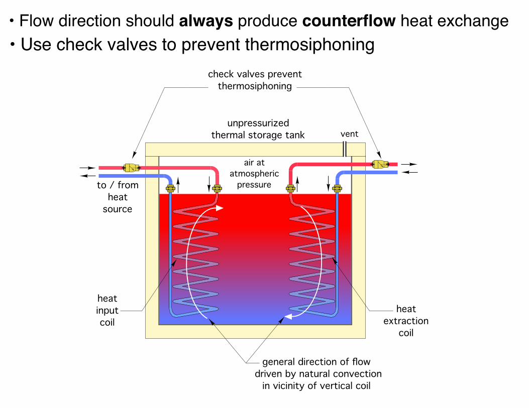
vent
to / from!heat
source
general direction of flow ! driven by natural convection!
in vicinity of vertical coil
heat !extraction !
coil
heat !input !coil
unpressurized thermal storage tank
check valves prevent thermosiphoning
air at atmospheric
pressure
• Flow direction should always produce counterflow heat exchange• Use check valves to prevent thermosiphoning

Limitations of internal coil heat exchangers
• They are expensive, typical copper coil ≥ $1000• Limited rate of heat transfer• Any maintenance requires opening tank - not easy
• Any maintenance may require major piping work inside tank
• Higher head loss requires more pumping power
• Very limited information for designers to accurately assess thermal performance over a range of temperature and flow conditions
versus alternative

Using EXTERNAL
heat exchangers

Brazed plate stainless steel heat exchangers
5”x12”
Images courtesy GEA FlatPlate
5”x20”
3”x5”

Brazed plate stainless steel heat exchangersAlways connect heat exchangers for counterflow
temperature temperature
Thi
Tho
Tci
Tco
∆T2
∆T1
hot fluid releasing heat
cool fluid absorbing heat
counterflow
Thi Tco
Tho Tci
Counterflow ALWAYS produces the highest “log mean temperature difference” (LMTD) across the heat exchanger. LMTD =
∆T1 − ∆T2
ln∆T1∆T2
⎛⎝⎜
⎞⎠⎟
The higher the LMTD, the greater the rate of heat transfer (all other factors the same).

http://flatplateselect.com
Sizing the brazed plate heat exchanger
Suggest a maximum approach temperature difference of 5 ºF under max. anticipated load.
FG5x12-305” wide x12” long -30 plates
Images courtesy GEA FlatPlate
from top of thermal storage(at lowest tank temperature)
load water out
load water inreturn to
thermal storage
max approach temp. difference
= 5 ºF
brazed platestainless steel
heat exchanger
Tin = Ttank/min. Tout = Ttank/min. − 5ºF( )
All heat exchanger create a “temperature penalty” between the material giving up heat, and the material receiving heat.
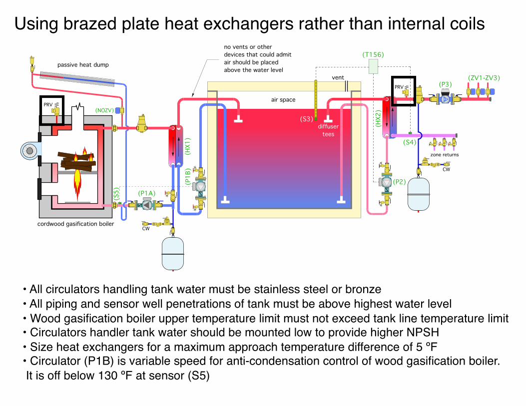
Using brazed plate heat exchangers rather than internal coils
vent
air space
no vents or other devices that could admitair should be placed above the water level
CW
(P2)
(HX2
)
(P1A)(P
1B)
(HX1
)
cordwood gasification boiler
passive heat dump
(NOZV)(S3)
(T156)
(P3)(ZV1-ZV3)
CW
(S4)zone returns
diffuser tees
(S5)
PRV
PRV
• All circulators handling tank water must be stainless steel or bronze• All piping and sensor well penetrations of tank must be above highest water level• Wood gasification boiler upper temperature limit must not exceed tank line temperature limit• Circulators handler tank water should be mounted low to provide higher NPSH• Size heat exchangers for a maximum approach temperature difference of 5 ºF• Circulator (P1B) is variable speed for anti-condensation control of wood gasification boiler. It is off below 130 ºF at sensor (S5)

Add and auxiliary boiler to previous system
• All circulators handling tank water must be stainless steel or bronze• All piping and sensor well penetrations of tank must be above highest water level• Wood gasification boiler upper temperature limit must not exceed tank line temperature limit• Circulators handler tank water should be mounted low to provide higher NPSH• Size heat exchangers for a maximum approach temperature difference of 5 ºF• Circulator (P1B) is variable speed for anti-condensation control of wood gasification boiler. It is off below 130 ºF at sensor (S5)
vent
air space
no vents or other devices that could admitair should be placed above the water level
CW
(P2)
(HX2
)
(P1A)
(P1B
)(H
X1)
cordwood gasification boiler
passive heat dump
(NOZV)(S3)
(T156)
(P3)(ZV1-ZV3)
CW(S4)
zone returns
diffuser tees
(S5)
modulating / condensing boiler (operates based on outdoor reset control)
diffuser tees
closely spaced
tees
PRV
supplytemperature
sensor

Add provision for domestic water heating to previous system
• Use indirect with large coil to enable max preheating& lowest aux boiler temperature• Aux boiler can “top off” temperature in indirect tank• ASSE 1017 setting no higher than 120 ºF
vent
air space
(S3)diffuser
tees
(P2)
(HX2
)
(T156)
(P3)(ZV1-ZV3)
CW(S4)
zone returns
modulating / condensing boiler
(operates based on outdoor reset control)
closely spaced
tees
PRV
supplytemperature
sensor
high capacity indirect tank
ASSE 1017 anti-scald valve
cold water
DHW
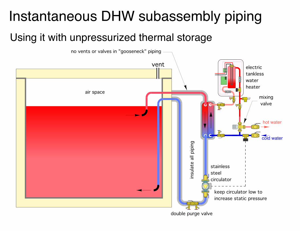
vent
!air space
hot water
cold water
!mixing valve
electric tankless!water heater
no vents or valves in "gooseneck" piping
keep circulator low to increase static pressure
stainless steel circulator
double purge valve
insu
late
all
pipi
ng
Instantaneous DHW subassembly pipingUsing it with unpressurized thermal storage

contactor
relay coil contacts
flow switch
electronics (PCB)
overtemp switch
element enclosure
240VAC input
setpoint adjustment
12KW unit, 50Amp / 240VAC
COLD
in
HOT
out
ETWH
hot water
cold water
isolation &!flushing valves
inlet!temperature !
sensor
heating!element
outlet!temperature !
sensor
flow !sensor
controls
240 VAC !electrical supply
PRV
Thermostatically controlled electric tankless water heaters
Image courtesy Eemax

thermostatically!controlled ETWH
240 VAC !electrical supply
relay!240 VAC coil!
in junction box
17
4
28
5
39
6
AB
120 VAC
N
storage to!HX circulator
PRV
Contactor inside Eemax EX012240Textra terminal on coil circuit of contactor
Using extra terminal on ETWH contactor to operate circulator
This eliminates the need for the flow switch.

flow switch
stainless steel !heat exchanger
to / from!other loads
HX flushing valves storage tank!(with varying temperature)
hot water
cold water
!mixing valve
electric tankless!water heater
to /
from
hea
t so
urce
(s)
swing check valve
circulator with check valve
circulator with check valve
Instantaneous DHW subassembly piping
NOTE: Check valve required on tank-to-HX circuit to prevent reverse flow during space heating

Add provision for domestic water heating to previous system
• Only one heat exchanger b/w tank water and domestic water
• Showing electric tankless aux heater - could also be a tank-type water heater
• Circulator (P4) must be stainless steel
• Combination isolation / flush valves on heat exchanger (HX3)
• Flow switch actives (P4) through a relay when DHW demand ≥ 0.7 gpm, of when demand ≤ 0.4 gpm
• ASSE 1017 setting no higher than 120 ºF
vent
air space
(P2)
(HX2
)
(S3)
(T156)
(P3)(ZV1-ZV3)
CW(S4)
zone returns
diffuser tees
modulating / condensing boiler
(operates based on outdoor reset control)
closely spaced
tees
PRV
supplytemperature
sensor
tankless electric water heater(or tank type water heater)
ASSE 1017 anti-scald valve
cold water
DHW
keep this length of pipe as short as possible and insulate
(P4)
(HX3
)

System using single external
heat exchanger
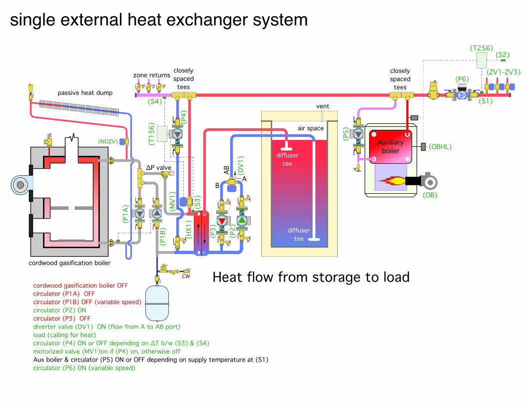
cordwood gasification boiler OFFcirculator (P1A) OFFcirculator (P1B) OFF (variable speed)circulator (P2) ONcirculator (P3) OFF diverter valve (DV1) ON (flow from A to AB port)load (calling for heat) circulator (P4) ON or OFF depending on ∆T b/w (S3) & (S4)motorized valve (MV1)on if (P4) on, otherwise offAux boiler & circulator (P5) ON or OFF depending on supply temperature at (S1)circulator (P6) ON (variable speed)
CW
(P1A
)
cordwood gasification boiler
passive heat dump
(NOZV)
(HX1
)(P
4)
(T15
6)
(S3)
(P1B
)
Heat flow from storage to load
Auxiliary boiler
(OB)
(OBHL)
(P6)
(S2)(T256)
(S1)
(ZV1-ZV3)
(P5)
(S4)
zone returnscloselyspacedtees
closelyspacedtees
(P2)
(P3)
AB
AB
(DV1
)
air space
diffuser tee
vent
diffuser tee∆P valve
(MV1
)
single external heat exchanger system

Single external heat exchanger system
multi-zone relay center
(X X)N
L
L Nzone 4 zone 5 zone 6
systempump zone 2 zone 3
zone thermostats(T1) (T2) (T3)
zone 1
zone valves(ZV2) (ZV3)(ZV1)
(P5)
aux boiler
T T
dedicatedcircuit
L1N
LN
serviceswitch
(LWCO2)
(S3)(S4)
(T156)
(T256)
(S1)
(S2)
24 VAC
L1 N
main switch(MS)
120 VAC
(X1)
(P4)
(P6)
(P2)(R2-1NC)
dedicatedcircuit
L1N
LN
serviceswitch
(LWCO1)
cordwoodgasification boiler
(P1B)
(P1A)
(S5)(P3)
(R1)
(R1-1)
(R2)
(DV1)
(NOZV)
(MV1)
See section 8 in Design Assistance Manual for complete description of operation.

RHNY IncentivesProgram System Type Installation Incentive Additional Incentive
Small Biomass Boiler
Advanced Cordwood Boiler with Thermal Storage
25% installed cost ($7,000 maximum) -
Recycling
$5,000/unit for old indoor/
outdoor wood boiler
or $2,500/unit for
old wood furnace
-
Small Pellet Boiler with Thermal Storage
≤120 kBtu/h (35 kW)
45% installed cost ($16,000 maximum)
Thermal Storage Adder
$5/gal for each gal above the
minimum thermal storage
requirement
-
≤300 kBtu/h (88 kW)
45% installed cost ($36,000 maximum) -
Large Biomass Boiler
Large Pellet Boiler with Thermal Storage
>300 kBtu/h (88 kW)
65% installed cost ($325,000 maximum)
Emission Control System
$40,000
Tandem Pellet Boiler with Thermal Storage
75% installed cost ($450,000 maximum)
Residential Pellet Stove Pellet Stove$1,500
($2,000 for income qualified residents)
-
Recycling
$500 (income qualified
residents only)
-

LMI Incentives - Boilers
Program System Type Market Rate Installation Incentive
LMI Installation Incentive
Small Biomass
Boiler
Advanced Cordwood Boiler with Thermal Storage
25% installed cost ($7,000 maximum)
65% installed cost ($18,000 maximum)
Small Pellet Boiler
with Thermal Storage
≤120 kBtu/h (35 kW)
45% installed cost ($16,000 maximum)
65% installed cost ($23,000 maximum)
For more information: • “Google” Renewable Heat NY• contact Sue Dougherty at NYSERDA [email protected]

All of these webinars will be posted on NYSERDA’s Renewable Heat NY website - under “training opportunities” link.
QUESTIONS ?
Thanks for attending this series of webinars.April 15 2021 1-2PMTitle: Creating A “Summer/Winter” Pellet Boiler SystemDescription: Many residential hydronics system include a provision for heating domestic water. When the pellet boiler is active it might be used for domestic water heating. However, it may not be practical to use the pellet boiler for DHW in summer. This webinar explains the options and shows how to create a system that can easily switch between a winter and summer mode.
May 13 2021 1-2 PMTitle: Piping Options For Multiple Thermal Storage TanksDescription: Some biomass boiler systems are installed in situations where it’s impractical to use a single large thermal storage tank. There are several multiple tank options that may be suitable. This webinar shows and describes several ways to configure a multiple tank array and explains tradeoffs in thermal performance. Example systems will be presented.
June 2021Title: Case study: A pellet boiler system for a highway garageDescription: Large slab-on-grade buildings are ideal candidates for combining a pellet boiler system with floor heating. This webinar will show the details for a system designed to heat a 13,000 square foot highway garage, including system piping, combustion air supply, thermal storage, controls, and a staged modulating/condensing auxiliary boiler system. The concepts shown are scaleable and repeatable for similar structures.
Additional webinars will be announced for fall 2021 (September, October, November)