using design patterns to develop high-performance object ...schmidt/pdf/stc-96.pdfsoftware...
TRANSCRIPT

Using Design Patterns to DevelopHigh-Performance Object-Oriented
Communication Software Frameworks
Douglas C. [email protected]
Department of Computer Science
Washington University, St. Louis 63130(TEL) 314-935-7538, (FAX) 314-935-7302
This paper appeared in the Proceedings of the 8th AnnualSoftware Technology Conference, Salt Lake City, Utah, April21–26, 1996.
1 Introduction
Developing extensible communication software that effec-tively utilizes concurrency on parallel platforms is a com-plex task. Despite dramatic increases in network and hostperformance, the design and implementation of communica-tion software remains a challenging problem. Moreover,the growing heterogeneity of hardware/software architec-tures and diversity of operating system platforms often makeit hard to directly reuse existing algorithms, detailed designs,interfaces, or implementations [1].
Two promising techniques for alleviating communicationsoftware complexity are design patterns and object-orientedframeworks. Design patterns capture the static and dy-namic structures and collaborations among components insuccessful solutions to problems that arise when buildingsoftware [2]. They help to enhance software quality by ad-dressing fundamental challenges in large-scale system de-velopment. These challenges include communication of ar-chitectural knowledge among developers; accommodatingnew design paradigms or architectural styles; resolving non-functional forces such as reusability, portability, and exten-sibility; and avoiding development traps and pitfalls that areusually learned only by experience.
An object-oriented communication framework is an inte-grated collection of components that cooperate to define areusable architecture for a family of related communicationsystems [3]. A framework provide a set of “semi-complete”applications that automate common communication softwaretasks (such as event demultiplexing, event handler dispatch-ing, connection establishment, routing, configuration of ap-plication services, and concurrency control [4]).
The emerging focus on design patterns and communicationframeworks in the object-oriented community offers softwaredevelopers both a language of discourse and a set of directlyreusable software components for capturing the essence ofsuccessful architectures, components, policies, services, andprogramming mechanisms. Once expressed in the pattern
form, reusable communication frameworks can be recast innew contexts to facilitate the widespread reuse of softwarearchitectures, detailed designs, algorithms, and implementa-tions.
The remainder of this paper is organized as follows: Sec-tion 2 outlines how patterns and frameworks have beenapplied to create a reusable object-oriented software archi-tecture for high-performance application-level Gateways;Section 3 outlines the components in a reusable communi-cation software framework used to build application-levelGateways; Section 4 examines the design patterns thatform the basis for the framework and Gateways; Section 5compares these patterns with those described in related work;and Section 6 presents concluding remarks.
2 A Reusable Object-Oriented Soft-ware Architecture for Application-level Gateways
This paper presents a case study illustrating how design pat-terns and frameworks are being applied in practice to facil-itate widespread reuse of software experience in productioncommunication systems. Patterns aid the development ofreusable components and frameworks in these systems bycapturing the structure and collaboration of participants in asoftware architecture at a higher level than (1) source codeand (2) object-oriented design models that focus on indi-vidual objects and classes. Thus, patterns enable widespreadreuse of software architecture, even when reuse of algorithms,implementations, interfaces, or detailed designs is not feasi-ble [1]. Likewise, frameworks can be viewed as concreterealizations of design patterns that facilitate direct reuse ofdesign and code. The particular system described in this casestudy is a reusable object-oriented software architecture forhigh-performance application-level Gateways.
2.1 System Overview
An application-level Gateway routes messages betweenPeers in a communication system (shown in Figure 1).The Gateway serves as a Mediator [5] that decouples co-
1

PEERS
NETWORK
GATEWAY
NETWORK
PEERS
1: send() 2: recv()3: route()4: send()
5: recv()
Figure 1: The Structure and Collaboration of Peers and theGateway
operating components in a software system and allows themto interact without having direct dependencies on each other[6]. Messages routed through a Gateway typically containpayloads such as commands, status messages, and bulk dataexchanged by Peers. These payloads are encapsulated inrouting messages.
This paper presents the object-oriented architecture anddesign of application-levelGateways in terms of the strate-gic design patterns and framework components used to guidetheir construction. Strategic design patterns have an exten-sive impact on the software architecture for solutions in a par-ticular domain. For example, the Router pattern described inSection 4.4 decouples input mechanisms from output mech-anisms to ensure that message processing is not disrupted orpostponed indefinitely when a Gateway experiences con-gestion or failure. This pattern greatly simplifies the designand quality of service in single-threaded Gateways that useconnection-oriented protocols such as TCP/IP or IPX/SPX.Application-level Gateway also utilize many tactical pat-terns (such as Factories and Iterators [5]). Tactical patternshave a relatively localized impact on a software architecturecompared with strategic patterns (which have more sweepingimplications on software architecture).
Due to stringent requirements for reliability, performance,and extensibility, application-level Gateways serve as ex-cellent exemplars for presenting the structure, participants,and consequences of design patterns that appear in manycommunication software systems. Figure 2 illustrates thestructure, associations, and internal and external collabo-rations among objects within a reusable software architec-ture for application-level Gateways.1 This architecture
1Relationships between componentsare illustrated throughout this paperusing Booch notation [7]. In these figures solid clouds indicate objects;nesting indicates composition relationships between objects; and undirectededges indicate some type of link exists between two objects. Dashed cloudsindicate classes; directed edges indicate inheritance relationships betweenclasses; and an undirected edge with a small circle at one end indicates either
is based on extensive experience developing connection-oriented Gateways for various commercial and academicprojects.
2.2 Impact of Patterns and Frameworks onSoftware Reuse
After building a range of communication systems, it be-came clear that the software architecture of application-levelGateways was largely independent of the protocols usedto route messages to Peers. This realization enabled thecomponents depicted in Figure 2 to be reused on many com-munication software projects. The ability to reuse these com-ponents so widely stems from two factors:
1. Understanding the strategic design patterns within thedomain of communication software – Some of these pat-terns have been documented individually in the patternsliterature (such as the Reactor [8], Connector [9], andthe Acceptor [10]). Section 4 describes several of thesepatterns in terms of an integrated system of design pat-terns that characterize the structure and collaborationof communication software patterns in the context ofapplication-level Gateways.
2. Implementing an object-oriented framework that imple-ments these common patterns – The systems describedin this paper were implemented with the ADAPTIVECommunication Environment (ACE) software [4]. TheACE framework implements a collection of design pat-terns that recur when building concurrent and reactive[8] communication software. ACE provides a rich setof reusable C++ wrappers, class categories, and frame-works that perform common communication softwaretasks (such as event demultiplexing, event handler dis-patching, connection establishment, routing, dynamicconfiguration of application services, and concurrencycontrol).
The design patterns and framework components describedin this paper have been used extensively throughout large-scale telecommunication and electronic medical imagingprojects [1, 11], as well as on academic research projects[4]. Both the patterns and the ACE components evolvedcontinuously over time via a continual process of “round tripgestalt” [7].
3 An Object-Oriented Framework forthe Gateway
This section describes how various communication compo-nents in the ACE framework were reused and extended toimplement the application-levelGateway architecture. Fol-lowing this overview,Section 4 examines the family of designpatterns that underly these reusable components.
a composition or uses relation between two classes; and a dashed directededge indicates template instantiation.
2

GATEWAYGATEWAY
CONNECTIONCONNECTION
REQUESTREQUEST CONNECTION
REQUEST
OUTGOING
MESSAGES
: Output: OutputChannelChannel
: Message: MessageQueueQueue: SOCK: SOCK
StreamStream
INCOMING
MESSAGES
: Acceptor: Acceptor
: SOCK: SOCKAcceptorAcceptor
: Connector: Connector
: SOCK: SOCKConnectorConnector
: Map: MapManagerManager
: Input: InputChannelChannel
: SOCK: SOCKStreamStream
: Routing: RoutingTableTable
: Map: MapManagerManager
: Output: OutputChannelChannel
: Message: MessageQueueQueue: SOCK: SOCK
StreamStream
: Input: InputChannelChannel
: SOCK: SOCKStreamStream
: Reactor: Reactor
PEERSPEERS
Figure 2: The Object-Oriented Gateway Software Archi-tecture
3.1 Applying ACE Components to the Gate-way
The primary ACE components used in the Gatewayinclude the Reactor [8], which encapsulates the UNIXselect event demultiplexingsystem call; SOCK Stream,SOCK Connector, and SOCK Acceptor [11], whichencapsulate the socket network programming interface; andMap Manager and Message Queue [4], which managecommunication messages efficiently. These components andtheir use in the Gateway are described below.
�Reactor: The Reactor [8] is a reusable object-orientedevent demultiplexing mechanism based on the Reactor pat-tern (outlined in Section 4.1). It channels all external eventstimuli in a Gateway to a single demultiplexing point. Thispermits single-threaded Gateways to wait on events han-dles, demultiplex events, and dispatch event handlers effi-ciently. An event indicates to a Gateway that somethingsignificant has occurred (e.g., the arrival of a new connectionor work request). The primary source of Gateway events isrouting messages that encapsulate various payloads (such ascommands, status messages, and bulk data). The Reactorprovides a coarse-grained form of concurrency control fora single-threaded Gateway. It serializes the invocation ofevent handlers at the level of event demultiplexing and dis-patching within a process. This eliminates the need for addi-tional synchronization mechanisms within a Gateway andalso minimizes context switching.
� Input Channel and Output Channel: These classesimplement the Router pattern (described in Section 4.4).Both classes inherit from a common ancestor: base classChannel (shown in Figure 3). This enables them to com-municate with Peers via an ACE SOCK Stream object
Channel
InputChannel
OutputChannel
SvcHandler
APPLICATION-
INDEPENDENT
APPLICATION-
SPECIFIC
Figure 3: Channel Inheritance Hierarchy
provided by the Channel base class. Input Channelsare responsible for routing incoming messages to their des-tination(s). The Reactor notifies an Input Channelwhen it detects an event on that channel’s SOCK Streamendpoint. TheInput Channel then receives and frames arouting message from that endpoint, consults the RoutingTable to determine the set of Output Channel des-tinations for the message, and asks the selected OutputChannels to forward the message to the appropriatePeerdestination(s).
An Output Channel is responsible for reliably deliv-ering routing messages to their destinations. It implements aflow control mechanism to buffer bursts of routing messagesthat cannot be sent immediately due to transient network con-gestion or lack of buffer space at a receiver. Flow controlensures that a source Peer does not send data faster than adestination Peer can buffer and process the data. For in-stance, if a destinationPeer runs out of buffer space the un-derlying TCP protocol instructs the associated Gateway’sOutput Channel to stop producing messages until thedestination Peer consumes the data.
A reusable ACE Message Queue object chains to-gether unsent messages in the order they must be deliv-ered when flow control mechanisms permit. Once the flowcontrol window opens up, the Reactor calls back to thehandle event method of the Output Channel. Thissignals the channel to start draining the Message Queueby sending messages to the Peer. If flow control occursagain this sequence of steps is repeated until all messages aredelivered.
� Routing Table: Input Channels use the RoutingTable to map addressing information contained in routingmessages sent by Peers to the appropriate set of OutputChannels. The Routing Table reuses the ACE MapManager collection class. A Map Manager is a param-eterized collection that efficiently maps external ids (e.g.,Peer routing addresses) onto internal ids (e.g., OutputChannels).
3

� Channel Connector and Channel Acceptor: TheChannel Connector and Channel Acceptor arereusable Factories [5] used by the Gateway to actively andpassively establish connections withPeers and produce theconnected Input Channels and Output Channelsdescribed above. These components are based on the Con-nector pattern (described in Section 4.2) and Acceptor pattern(described in Section 4.3).
To increase system flexibility, connections can be estab-lished in two ways:
1. From the Gateway to the Peers – which is typicallydone when the Gateway first starts up to establish theinitial system configuration of Peers.
2. From a Peer to theGateway– which is typically doneonce the system is running when a new Peer wants tosend or receive routing messages.
In a large system several hundred Peers may be connectedto a single Gateway. To expedite connection setup initi-ated from the Gateway to all these Peers, the Gatewayuses the asynchronous connection mechanisms provided bythe Channel Connector and its underlying ACE SOCKConnector [11]. When a SOCK Connector connectstwo socket endpoints via TCP it produces a SOCK Streamobject, which is used to exchange data between that Peerand the Gateway.
To decrease connection establishment latency, theGateway’s Channel Connector initiates all connec-tions asynchronously rather than connecting each Peer syn-chronously. Asynchrony helps decrease connection latencyover long delay paths (such as wide-area networks (WANs)build over satellites or long haul terrestrial links).
3.2 Motivation for Using ACE
To enhance performance and interoperability, as well as toreuse existing tracking station software and hardware, con-nections between the Gateway control facility applicationsand tracking stations are implemented using the TCP/IPcommunication protocol suite. In particular, the Gatewaydoes not higher-level distributed object computing tools likeCORBA [12] for its communication infrastructure. There areseveral reasons for this decision:
� The performance of CORBA implementations has gen-erally not been optimized to eliminate key sources ofcommunication overhead for transmitting bulk data overhigh-speed, long-delay networks [11, 13]. This over-head stems from non-optimized presentation layer con-versions, data copying, and memory management, inef-ficient receiver-side demultiplexing and dispatching op-erations, synchronous stop-and-wait flow control, andnon-adaptive retransmission timer schemes.
� CORBA is not well suited to handle the peer-to-peer,asynchronous behavior of the Gateway. In partic-ular, many CORBA implementations do not support
non-blocking method invocations (even for onewayoperations). The problem is that flow control mecha-nisms provided by the de facto CORBA transport proto-col (TCP) may indefinitely block a method that outputsmessages. TCP flow control ensures that a fast pro-ducer does not send data faster than a slower consumercan buffer and process the data. If the consumer runsout of buffer space TCP instructs the producer to stoptransmitting until the consumer removes the data fromthe OS buffer layer. Many versions of CORBA block asender when a TCP connection encounters flow control.Therefore, it is hard to write a robust, single-threadedapplication that will not hang indefinitely.
� Legacy communication applications and protocol stacksdo not conform to the CORBA interface nor its wireprotocol [14]. When combined with the output block-ing problem described above, the level of effort requiredto port legacy applications to CORBA clearly exceedsthe benefits of using a single OO communication infras-tructure.
Since the use of CORBA was infeasible, the ACE frameworkwas combined with the design patterns described below tobuild a robust, extensible, and high-performance Gateway.
4 A System of Design Patterns for theGateway
A design pattern is a recurring solution to a design problemwithin a particular domain (such as business data processing,telecommunications, graphical user interfaces, databases, ordistributed communication software). A design pattern de-scription typically conveys the following information [5]:
� The intent of the pattern
� The design forces that motivate the pattern
� The solution to these forces
� The related classes and their roles in the solution
� The responsibilities and dynamic collaborations amongclasses
� The positive and negative consequences of using thepattern
� Guidance for implementors of the pattern
� Example source code illustrating how the pattern is ap-plied
� References to related work.
A family of design patterns (also called a “pattern lan-guage” [15] or a “pattern system” [6]) is a set of relatedpatterns that collaborate to solve a broader set of problemsthat arise in a domain. A pattern family description illus-trates how the constituent patterns interact to form a web ofdesign solutions [6]. Figure 4 illustrates the key strategic and
4

ConnectorConnectorActiveActiveObjectObject
ReactorReactor
BuilderBuilderIteratorIterator AdapterAdapterTemplateTemplateMethodMethod
TACTICALTACTICAL
PATTERNSPATTERNS
STRATEGIC
PATTERNS
AcceptorAcceptor
RouterRouter
ProxyProxy
Figure 4: The Family of Patterns for the Gateway
tactical patterns in a family of patterns for singled-threaded,connection-oriented application-level Gateways. The fol-lowing four strategic patterns related to connection-oriented,application-level Gateways are examined in this section:
� The Reactor pattern – decouples event demultiplexingand event handler dispatching from services performedin response to events;
� The Connector pattern – decouples active service ini-tialization from the tasks service performed once theservice is initialized.
� The Acceptor pattern – decouples passive service ini-tialization from the tasks performed once the service isinitialized;
� The Router pattern – decouples input mechanisms fromoutput mechanisms to prevent blocking in a single-threaded Gateway.
These patterns form the family of patterns underlyingthe object-oriented software architecture of application-levelGateways described in Section 2. This paper focuseson these strategic patterns since they are crucial to the ar-chitecture, design, and implementation of communicationGateways. Moreover, these strategic patterns express de-sign expertise that can be reused across a broad range of com-munication software. This family of patterns was discoveredbased on extensive design and implementation experiencewith communication systems (including on-line transactionprocessing systems [16], telecommunication switch manage-ment systems [1], electronic medical imaging systems [11],and parallel communication subsystems [4]).
Due to space limitations, the strategic Gateway patternsare not described as thoroughly as the patterns in catalogssuch as [5, 6], nor are sample implementations provided.Likewise, the tactical patterns shown in Figure 4 are not de-scribed in detail either. In contrast to strategic patterns (which
Reactor
handle_events()register_handler(eh, type)remove_handler(eh, type) Event HandlerEvent Handler
handle_event(type)get_handle()
Ann
11
select (handles)foreach h in handles loop table[h]->handle_event (type)end loop
nn
11
APPLIC
ATIO
N
APPLIC
ATIO
N--SPECIFIC
SPECIFIC
APPLIC
ATIO
N
APPLIC
ATIO
N--IND
EPE
ND
EN
T
IND
EPE
ND
EN
T
HandlesHandles
11
11
ConcreteConcreteEventEvent
HandlerHandler
Figure 5: Structure and Participants in the Reactor Pattern
are often domain-specific and have sweeping design impli-cations), tactical patterns are generally domain-independentand have a relatively localized impact on a software architec-ture. For instance, Iterator [5] is a tactical pattern used in theGateway to allow Channels in the Routing Tableto be processed sequentially without violating data encap-sulation. Although this pattern is domain-independent andthus widely applicable, the problem it addresses does notimpact the application-level Gateway software architec-ture as strongly as the strategic patterns described in thispaper. Other tactical patterns used extensively throughoutthe Gateway include the following:
� Factory Methods – which decouple object creation fromobject use.
� Iterators – which decouple sequential access to a con-tainer from the representation of the container.
� Adapters – which encapsulate existing procedural inter-faces to make them object-oriented.
� Template Method – where an algorithm is written suchthat some steps are supplied by a derived class.
As described below, many of these tactic patterns form thebasis for the strategic patterns presented in this paper.
4.1 The Reactor Pattern
Intent: The Reactor pattern decouples event demultiplex-ing and event handler dispatching from the services per-formed in response to events.
Forces: The Reactor pattern resolves the following forcesthat impact the design of event-driven communication soft-ware:
1. The need to demultiplex multiple types of events frommultiple sources of events efficiently within a single
5

mainmainprogramprogram
REGISTER HANDLER
DISPATCH HANDLER(S)
RUN EVENT LOOP
EXTRACT HANDLE
INITIALIZE
callback :Concrete
Event_Handler
handle_events()
handle_event(event_type)
reactor :Reactor
get_handle()
Reactor()
register_handler(callback)
select()
: Handles
WAIT FOR EVENTS
INIT
IAL
IZA
TIO
NIN
ITIA
LIZ
AT
ION
MO
DE
MO
DE
EV
EN
T H
AN
DL
ING
EV
EN
T H
AN
DL
ING
MO
DE
MO
DE
Figure 6: Object Interaction Diagram for the Reactor Pattern
thread of control – A Reactor serializes application eventhandling within a process at the level of event demul-tiplexing. By using the Reactor pattern the need formore complicated threading, synchronization, or lock-ing within an application is often eliminated.
2. The need to extend application behavior without requir-ing changes to the event dispatching framework – TheReactor factors out the demultiplexing and dispatchingmechanisms (which are independent of an applicationand thus reusable) from the event handler processingpolicies (which are specific to an application).
Structure and Participants: Figure 5 illustrates the struc-ture and participants in the Reactor pattern. The Reactordefines an interface for registering, removing, and dispatch-ing Concrete Event Handler objects. An imple-mentation of this interface provides a set of application-independent mechanisms. These mechanisms perform eventdemultiplexing and dispatching of application-specific eventhandlers in response to events.
An Event Handler specifies an abstract interface usedby the Reactor to dispatch callback methods defined byobjects that register to handle input, output, signal, and time-out events of interest. Each Concrete Event Handlerselectively implements callback method(s) to process eventsin an application-specific manner.
Collaborations: Figure 6 illustrates the collaborations be-tween participants in the Reactor pattern. These collabora-tions are divided into the following two phases:
1. Initialization phase – where Concrete EventHandler objects are registered with the Reactor
2. Event handling phase – where methods on the objectsare called back to handle particular types of events.
Uses: Figure 7 outlines how the Reactor is used in aGateway. A Reactor object dispatches incoming routingmessages to the associated Input Channel, where theyare routed to Output Channels. The Reactor also en-sures that outgoing routingmessages are eventually deliveredon flow controlled Output Channels (described in Sec-tion 4.4). In addition, the Reactor dispatches events that
:: Reactor Reactor
REGISTEREDREGISTERED
OBJECTSOBJECTS
FR
AM
EW
OR
KF
RA
ME
WO
RK
LE
VE
LL
EV
EL
KE
RN
EL
KE
RN
EL
LE
VE
LL
EV
EL
AP
PL
ICA
TIO
NA
PP
LIC
AT
ION
LE
VE
LL
EV
EL
OS EVENT DEMULTIPLEXING INTERFACE
:Timer:TimerQueueQueue
: Signal: SignalHandlersHandlers
: Handle: HandleTableTable
: Event: EventHandlerHandler
: Output: OutputChannelChannel
: Event: EventHandlerHandler
: Output: OutputChannelChannel
: Event: EventHandlerHandler
: Input: InputChannelChannel
1: handle_event()1: handle_event()
4: send(msg)4: send(msg)
2: recv(msg)2: recv(msg)3: route(msg)3: route(msg)
Figure 7: Using the Reactor Pattern in the Gateway
indicate the completion status of connections actively initi-ated asynchronously (used by the Channel Connectordescribed in Section 4.2), as well as to accept passively ini-tiated connections (used by the Channel Acceptor de-scribed in Section 4.3).
The Reactor pattern has been used in many single-threadedevent-driven frameworks (such as the Motif, Interviews [17],System V STREAMS [18], the ASX object-oriented commu-nication framework [4], and implementations of DCE andCORBA). In addition, it forms as the foundation for the otherstrategic patterns for application-levelGateways presentedbelow.
4.2 The Connector Pattern
Intent: The Connector pattern decouples active2 serviceinitialization from the tasks performed once a service is ini-tialized.
Forces: The Connector pattern resolves the followingforces that impact the design of connection-oriented com-munication software (particularly clients) when using lower-level network programming interfaces (like sockets [19] andTLI [20]):
1. The need to reuse active connection establishment codefor each new service – The Connector pattern permitskey characteristics of services (such as the concurrencystrategy or the data format) to evolve independently andtransparently from the mechanisms used to establish theconnections. Since service characteristics change morefrequently than connection establishment mechanisms
2Communication software is typified by asymmetric roles for estab-lishing connections between clients and servers. In general, servers (whoplay a passive role) listen for clients (who play an active role) to initiateconnections.
6
ReactorReactor11nn
EventEventHandlerHandler
ConnectorConnectorconnect_svc_handler()activate_svc_handler()handle_output()connect(sh, addr)
SVC_HANDLERSVC_HANDLER
PEER_CONNECTORPEER_CONNECTOR
ConcreteConcreteConnectorConnector
Concrete_Svc_HandlerConcrete_Svc_Handler
SOCK_ConnectorSOCK_Connector11
ConcreteConcreteSvc HandlerSvc Handler
SOCK StreamSOCK Stream
open()
nn
RE
AC
TIV
ER
EA
CT
IVE
LA
YE
RL
AY
ER
CO
NN
EC
TIO
NC
ON
NE
CT
ION
LA
YE
RL
AY
ER
AP
PL
ICA
TIO
NA
PP
LIC
AT
ION
LA
YE
RL
AY
ER
handle_output()
AA
connect_svc_handlerconnect_svc_handler
(sh, addr); (sh, addr);1:1:
Svc HandlerSvc Handler
PEER_STREAMPEER_STREAM
open() AA
INITS
activate_svc_handleractivate_svc_handler
(sh); (sh);2:2:
nn
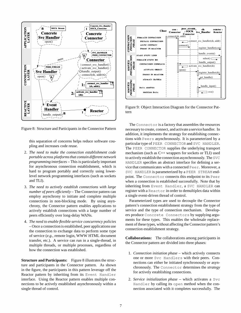
Figure 8: Structure and Participants in the Connector Pattern
this separation of concerns helps reduce software cou-pling and increases code reuse.
2. The need to make the connection establishment codeportable across platforms that contain different networkprogramming interfaces – This is particularly importantfor asynchronous connection establishment, which ishard to program portably and correctly using lower-level network programming interfaces (such as socketsand TLI).
3. The need to actively establish connections with largenumber of peers efficiently – The Connector pattern canemploy asynchrony to initiate and complete multipleconnections in non-blocking mode. By using asyn-chrony, the Connector pattern enables applications toactively establish connections with a large number ofpeers efficiently over long-delay WANs.
4. The need to enable flexible service concurrency policies– Once a connection is established, peer applications usethe connection to exchange data to perform some typeof service (e.g., remote login, WWW HTML documenttransfer, etc.). A service can run in a single-thread, inmultiple threads, or multiple processes, regardless ofhow the connection was established.
Structure and Participants: Figure 8 illustrates the struc-ture and participants in the Connector pattern. As shownin the figure, the participants in this pattern leverage off theReactor pattern by inheriting from its Event Handlerinterface. Using the Reactor pattern enables multiple con-nections to be actively established asynchronously within asingle thread of control.
ClientClient
FOREACH CONNECTIONFOREACH CONNECTION
INITIATE CONNECTION INITIATE CONNECTION
ASYNC CONNECT ASYNC CONNECT
INSERT IN REACTOR INSERT IN REACTOR
START EVENT LOOPSTART EVENT LOOP
FOREACH EVENT DOFOREACH EVENT DO
handle_events()
select()
CONNECTION COMPLETECONNECTION COMPLETE
INSERT IN REACTORINSERT IN REACTOR
con :con :ConnectorConnector
handle_input()
reactor :reactor :ReactorReactor
sh:sh:Svc_HandlerSvc_Handler
handle_output()
register_handler(sh)
get_handle()EXTRACT HANDLEEXTRACT HANDLE
DATA ARRIVESDATA ARRIVES
svc()PROCESS DATAPROCESS DATA
connect(sh, addr)
connect()
ACTIVATE OBJECTACTIVATE OBJECT
register_handler(con)
peer_stream_peer_stream_: SOCK: SOCK
ConnectorConnector
CO
NN
EC
TIO
NC
ON
NE
CT
ION
INIT
IAT
ION
INIT
IAT
ION
PH
AS
EP
HA
SE
SE
RV
ICE
SE
RV
ICE
INIT
IAL
IZA
TIO
NIN
ITIA
LIZ
AT
ION
PH
AS
EP
HA
SE
SE
RV
ICE
SE
RV
ICE
PR
OC
ES
SIN
GP
RO
CE
SS
ING
PH
AS
EP
HA
SE
activate_svc_handler(sh)
connect_svc_handler(sh, addr)
open()
Figure 9: Object Interaction Diagram for the Connector Pat-tern
The Connector is a factory that assembles the resourcesnecessary to create, connect, and activate a service handler. Inaddition, it implements the strategy for establishing connec-tions with Peers asynchronously. It is parameterized by aparticular type of PEER CONNECTOR and SVC HANDLER.The PEER CONNECTOR supplies the underlying transportmechanism (such as C++ wrappers for sockets or TLI) usedto actively establish the connection asynchronously. TheSVCHANDLER specifies an abstract interface for defining a ser-vice that communicates with a connected Peer. Moreover, aSVC HANDLER is parameterized by a PEER STREAM end-point. The Connector connects this endpoint to its Peerwhen a connection is established successfully. Note that byinheriting from Event Handler, a SVC HANDLER canregister with a Reactor in order to demultiplex data withina single event-driven thread of control.
Parameterized types are used to decouple the Connectorpattern’s connection establishment strategy from the type ofservice and the type of connection mechanism. Develop-ers produce Concrete Connectors by supplying argu-ments for these types. This enables the wholesale replace-ment of these types, without affecting the Connector pattern’sconnection establishment strategy.
Collaborations: The collaborations among participants inthe Connector pattern are divided into three phases:
1. Connection initiation phase – which actively connectsone or more Svc Handlers with their peers. Con-nections can either be initiated synchronously or asyn-chronously. The Connector determines the strategyfor actively establishing connections.
2. Service initialization phase – which activates a SvcHandler by calling its open method when the con-nection associated with it completes successfully. The
7

openmethod of the Svc Handler performs service-specific initialization.
3. Service processing phase – which performs theapplication-specific service processing using the dataexchanged between the Svc Handler and its con-nected peer. Depending on the open method of SvcHandler, this phase may employ the Reactor pattern(or some other type of concurrency mechanisms suchas Active Objects [21]) to process incoming events.For example, when commands arrive at a CommandHandler in the Gateway, the Reactor dispatchesEvent Handlers to frame the commands, determineoutgoing routes, and deliver the commands to their des-tinations.
Figure 9 illustrates the collaboration among participants inthe Connector pattern using asynchronous connection estab-lishment.
Uses: The Gateway uses the Connector pattern to sim-plify the task of connecting to a large number of Peers.During Gateway initialization, a list of Peer port ad-dresses are read from a configuration file. These addressesare bound to dynamically created Channels (which inheritfrom Svc Handler). All connections are then initiatedasynchronously and the connections are completed in paral-lel.
Figure 10 illustrates the relationship between participantsin the Connector pattern after four connections have beenestablished. Three other connections that have not yetcompleted are owned by the Connector. As shown inthis figure, the Connector maintains a table of the threeChannels whose connections are pending completion. Asconnections complete, the Connector removes the con-nected Channel from its table and activates it. Once ac-tivated, Input Channels register themselves with theReactor. Henceforth, when routing messages arrive,Input Channels receive and forward them to OutputChannels, which deliver the messages to their destina-tions (these activities are described in Section 4.4). InputChannels and Output Channels are objects residingin the Gateway. In contrast, the original source and theintended destination(s) of routing messages reside on otherhosts across the network.
In addition to establishing connections, a Gateway canuse the Connector in conjunction with the Reactor toensure that connections are restarted when errors occur. Thisenhances the Gateway’s fault tolerance by ensuring thatchannels are automatically reinitiated when they disconnectunexpectedly (e.g., if a Peer crashes or an excessive amountof data is queued at an Output Channel due to net-work congestion). If a connection fails unexpectedly, anexponential-backoff algorithm can be implemented using theReactor to restart the connection efficiently.
4.3 The Acceptor Pattern
: Connector
: ReactorPENDING
CONNECTIONS
ACTIVE
CONNECTIONS
: SvcHandler
: Channel
: SvcHandler
: Channel
: SvcHandler
: Channel
: SvcHandler
: Channel
: SvcHandler
: Channel
: SvcHandler
: Channel: Svc
Handler
: Channel
Figure 10: Using the Connector Pattern in the Gateway
ReactorReactor11
AcceptorAcceptor
SERVICE_HANDLER
PEER_ACCEPTOR
ConcreteConcreteAcceptorAcceptor
Concrete_Service_HandlerConcrete_Service_Handler
SOCK_AcceptorSOCK_Acceptor11ConcreteConcreteServiceServiceHandlerHandler
SOCK StreamSOCK Streamnn
RE
AC
TIV
ER
EA
CT
IVE
LA
YE
RL
AY
ER
CO
NN
EC
TIO
NC
ON
NE
CT
ION
LA
YE
RL
AY
ER
AP
PL
ICA
TIO
NA
PP
LIC
AT
ION
LA
YE
RL
AY
ER
ACTIVATES
sh = make_service_handler();sh = make_service_handler();
accept_service_handler (sh);accept_service_handler (sh);
activate_service_handler (sh);activate_service_handler (sh);
nn
EventEventHandlerHandler
AA
make_service_handler()accept_service_handler()activate_service_handler()open()accept()
ServiceServiceHandlerHandler
PEER_STREAMPEER_STREAM
open() AA
Figure 11: Structure and Participants in the Acceptor Pattern
8

Intent: The Acceptor pattern decouples passive service ini-tialization from the tasks performed once the service is ini-tialized.
Forces: The Acceptor pattern resolves the following forcesthat impact the design of connection-oriented communica-tion software (particularly servers) when using lower-levelnetwork programming interfaces (like sockets [19] and TLI[20]):
1. The need to reuse passive connection establishment codefor each new service – The Acceptor pattern permitskey characteristics of services (such as the concurrencystrategy or the data format) to evolve independently andtransparently from the mechanisms used to establish theconnections. Since service characteristics change morefrequently than connection establishment mechanismsthis separation of concerns helps reduce software cou-pling and increases code reuse.
2. The need to make the connection establishment codeportable across platforms that contain different networkprogramming interfaces – Parameterizing the Accep-tor’s mechanisms for accepting connections and per-forming services helps to improve portability by allow-ing the wholesale replacement of these mechanisms.This makes the connection establishment code portableacross platforms that contain different network program-ming interfaces (such as sockets but not TLI, or viceversa).
3. The need to enable flexible service concurrency policies– Once a connection is established, peer applications usethe connection to exchange data to perform some typeof service (e.g., remote login, WWW HTML documenttransfer, etc.). A service can run in a single-thread, inmultiple threads, or multiple processes, regardless ofhow the connection was established.
4. The need to ensure that a passive-mode I/O handle isnot accidentally used to read or write data – By stronglydecoupling the Connector from the Svc Handlerpassive-mode listener endpoints cannot accidentally beused incorrectly (e.g., to try to read or write data ona passive-mode listener socket used to accept connec-tions).
The Acceptor pattern is the “dual” of the Connector pat-tern described in Section 4.2. Unlike the Connector pattern(which establishes connections actively), the Acceptor pat-tern establishes connections passively.
Structure and Participants: Figure 11 illustrates thestructure and participants in the Acceptor pattern. This pat-tern leverages off the Reactor pattern’s Reactor to pas-sively establish multiple connections within a single threadof control. The Acceptor implements the strategy forestablishing connections with Peers. It is parameterizedby concrete types that conform to the interfaces of the for-mal template arguments SVC HANDLER (which performs a
ServerServer
REGISTER HANDLERREGISTER HANDLER
START EVENT LOOPSTART EVENT LOOP
CONNECTION EVENTCONNECTION EVENT
REGISTER HANDLERREGISTER HANDLER
FOR CLIENT FOR CLIENT I/OI/O
FOREACH EVENT DOFOREACH EVENT DO
EXTRACT HANDLEEXTRACT HANDLE
INITIALIZE PASSIVEINITIALIZE PASSIVE
ENDPOINTENDPOINT
acc :acc :AcceptorAcceptor
handle_event()
handle_close()
reactor :reactor :ReactorReactor
select()
sh:sh:Svc_HandlerSvc_Handler
handle_event()
register_handler(sh)
get_handle()EXTRACT HANDLEEXTRACT HANDLE
DATA EVENTDATA EVENT
CLIENT SHUTDOWNCLIENT SHUTDOWN
svc()PROCESS MSGPROCESS MSG
open()
CREATECREATE,, ACCEPT ACCEPT,,AND ACTIVATE OBJECTAND ACTIVATE OBJECT
SERVER SHUTDOWNSERVER SHUTDOWNhandle_close()
: SOCK: SOCKAcceptorAcceptor
handle_events()
get_handle()
register_handler(acc)
sh = make_svc_handler()accept_svc_handler (sh)activate_svc_handler (sh)
open()
EN
DP
OIN
TE
ND
PO
INT
INIT
IAL
IZA
TIO
NIN
ITIA
LIZ
AT
ION
PH
AS
EP
HA
SE
SE
RV
ICE
SE
RV
ICE
INIT
IAL
IZA
TIO
NIN
ITIA
LIZ
AT
ION
PH
AS
EP
HA
SE
SE
RV
ICE
SE
RV
ICE
PR
OC
ES
SIN
GP
RO
CE
SS
ING
PH
AS
EP
HA
SE
Figure 12: Object Interaction Diagram for the Acceptor Pat-tern
service in conjunction with a connected Peer) and PEERACCEPTOR (which is the underlying mechanism used topassively establish the connection). The Svc Handlershown in Figure 11 is a concrete type that defines the in-terface for an application-specific service. It inherits fromEvent Handler (shown in Figure 5), which allows it tobe dispatched by the Reactor when connection events oc-cur. In addition,Svc Handler is parameterized by aPEERSTREAM endpoint. The Acceptor associates this endpointwith its Peer when a connection is established successfully.
As with the Connector pattern, parameterized types areused to enhance portability since the Acceptor pattern’s con-nection establishment strategy is independent of the type ofservice and the type of IPC mechanism. Programmers supplyconcrete arguments for these types to produce a ConcreteAcceptor. Note that a similar degree of decoupling couldbe achieved via inheritance and dynamic binding by usingthe Abstract Factory or Factory Method patterns described in[5]. Parameterized types were used to implement this patternsince they improve run-time efficiency at the expense of ad-ditional compile-time and link-timetime and space overhead.
Collaboration: Figure 12 illustrates the collaborationamong participants in the Acceptor pattern. These collab-orations are divided into three phases:
1. Endpoint initialization phase – which creates a passive-mode endpoint (encapsulated by PEER ACCEPTOR)that is bound to a network address (such as an IP addressand port number). The passive-mode endpoint listensfor connection requests from peers. This endpoint isregistered with the Reactor, which then goes intoan event loop waiting on that endpoint for connectionrequests to arrive from peers.
2. Service activation phase – Since an Acceptor in-herits from an Event Handler the Reactor can
9
: Input: InputAcceptorAcceptor
:: Reactor Reactor
ACTIVE
CONNECTIONS
: SvcHandler
: Input: InputChannelChannel
: Svc: SvcHandlerHandler
: Output: OutputChannelChannel
: Svc: SvcHandlerHandler
: Output: OutputChannelChannel
: Svc: SvcHandlerHandler
: Input: InputChannelChannel
PASSIVE
LISTENERS: Output: OutputAcceptorAcceptor
Figure 13: Using the Acceptor Pattern in the Gateway
dispatch the Acceptor’s handle event methodwhen connection events arrive. When connectionsarrive, the Reactor calls back to the Acceptor’shandle event method. This Template Method [5]performs the Acceptor’s Svc Handler activationstrategy. This strategy assembles the resources neces-sary to create a new Concrete Svc Handler ob-ject, accept the connection into this object, and activatethe Svc Handler by calling its open method.
3. Service processing phase – once activated, the SvcHandler processes incoming event messages arrivingon thePEER STREAM. ASvc Handlerwill processincoming event messages using the Reactor pattern orsome other form of concurrent event handling such asthe Active Object pattern [21]. The concurrency strat-egy used by a Svc Handler is defined by its openmethod.
Uses: Figure 13 illustrates how the Acceptor pattern is usedby the Gateway. The Gateway uses this pattern when itplays the passive connection role. In this case, the Peersconnect to Gateway, which uses the Acceptor pattern todecouple the activity of connecting passively from the routingservice provided once the connection is established.
The intent and general architecture of the Acceptor patternis also found in network server management tools likeinetd[19] and listen [20]. These tools utilize a master acceptorprocess that listens for connections on a set of communica-tion ports. Each port is associated with a communication-related service (such as the standard Internet services ftp,telnet, daytime, and echo). When a service requestarrives on a monitored port, the acceptor process accepts therequest and dispatches an appropriate pre-registered handlerthat performs the service.
RoutingRoutingTableTable
find()
OutputOutputChannelChannel
send_msg()put()
InputInputChannelChannel
recv_msg()
1
nn
I/O
I/O
LA
YE
RL
AY
ER
RO
UT
ING
RO
UT
ING
LA
YE
RL
AY
ER
MessageMessageQueueQueue
EVENT SOURCE AND SINKEVENT SOURCE AND SINK
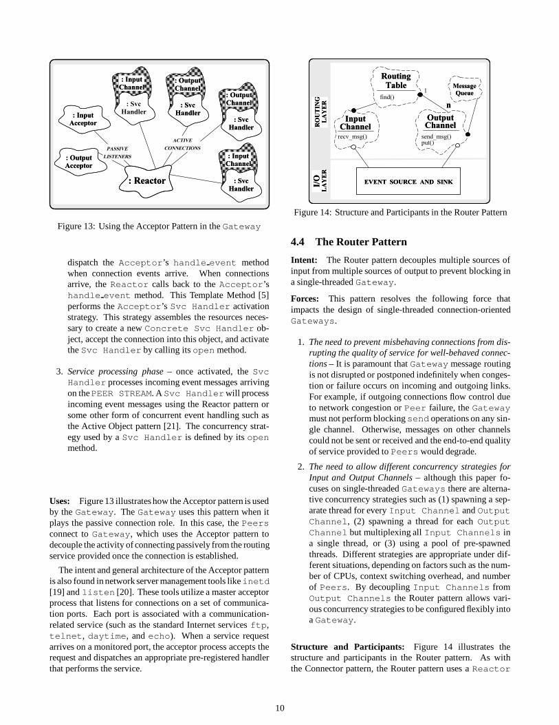
Figure 14: Structure and Participants in the Router Pattern
4.4 The Router Pattern
Intent: The Router pattern decouples multiple sources ofinput from multiple sources of output to prevent blocking ina single-threaded Gateway.
Forces: This pattern resolves the following force thatimpacts the design of single-threaded connection-orientedGateways.
1. The need to prevent misbehaving connections from dis-rupting the quality of service for well-behaved connec-tions – It is paramount that Gateway message routingis not disrupted or postponed indefinitely when conges-tion or failure occurs on incoming and outgoing links.For example, if outgoing connections flow control dueto network congestion or Peer failure, the Gatewaymust not perform blockingsend operations on any sin-gle channel. Otherwise, messages on other channelscould not be sent or received and the end-to-end qualityof service provided to Peers would degrade.
2. The need to allow different concurrency strategies forInput and Output Channels – although this paper fo-cuses on single-threaded Gateways there are alterna-tive concurrency strategies such as (1) spawning a sep-arate thread for every Input Channel and OutputChannel, (2) spawning a thread for each OutputChannel but multiplexing all Input Channels ina single thread, or (3) using a pool of pre-spawnedthreads. Different strategies are appropriate under dif-ferent situations, depending on factors such as the num-ber of CPUs, context switching overhead, and numberof Peers. By decoupling Input Channels fromOutput Channels the Router pattern allows vari-ous concurrency strategies to be configured flexibly intoa Gateway.
Structure and Participants: Figure 14 illustrates thestructure and participants in the Router pattern. As withthe Connector pattern, the Router pattern uses a Reactor
10

to allow multiple events on different connections to be de-multiplexed within a single thread of control. The InputChannels and Output Channels inherit indirectlyfrom Event Handler. This enables the Reactor todispatch their handle event methods when messages ar-rive and flow control conditions subside, respectively. AnInput Channel uses a Routing Table to map rout-ing messages onto one or moreOutput Channels. Sincethe Input Channels are separate from the OutputChannels their implementations may vary independently.This decoupling is important since it allows different concur-rency strategies to be used for input and output.
Although TCP connections are bi-directional, data sentfrom Peer to the Gateway use a different connection thandata sent from the Gateway to the Peer. There are sev-eral advantages to separating input connections from outputconnections in this manner. First, it simplifies the construc-tion of Gateway Routing Tables. Second, it allowsmore flexibility in connection configuration and concurrencystrategies. Finally, it enhances reliability if errors occur on aconnection (since Input and Output Channels can bereconnected independently).
Collaborations: Figure 15 illustrates the collaborationamong participants in the Router pattern. These collabo-rations may be divided into three phases:
1. Input processing – in this phase Input Channelsuse non-blocking I/O to incrementally reassemble in-coming TCP segments into complete routing messages;
2. Route selection – in this phase Input Channelsconsult a Routing Table to select the OutputChannels responsible for sending the routing mes-sages;
3. Output processing – in this phase the selected OutputChannels transmit the routing messages to their des-tination(s) without blocking the process.
Uses: Figure 16 illustrates how the Router pattern is used intheGateway. Input Channel andOutput Channelprocessing routes messages within a single thread of controlby using the Reactor object. The use of single-threadingeliminates the overhead of synchronization (since access toshared objects like the Routing Table need not be seri-alized) and context switching (since message routing occursin a single thread).
The primary challenge of building a reliable, single-threaded, connection-oriented Gateway revolves aroundavoiding blocking I/O. This is necessary to reliably man-age flow control on Output Channels. If the Gatewaywere to block indefinitely when sending on a congestedconnections incoming messages could not be routed, evenif those messages were destined for non-flow controlledOutput Channels.
Figure 16 illustrates the sequence of collaborations be-tween Router pattern participants in a single-threaded
: Routing: RoutingTableTable
recv_msg()
find ()
I/OI/OLayerLayer
: Input: InputChannelChannel
FIND DESTINATIONSFIND DESTINATIONS
ROUTE MSGROUTE MSG
main()main()
SEND MSGSEND MSG
((QUEUE IF FLOWQUEUE IF FLOW
CONTROLLEDCONTROLLED))
put()
wakeup()FLOW CONTROLFLOW CONTROL
ABATESABATES
DEQUEUE AND SENDDEQUEUE AND SEND
MSG MSG ((REQUEUE IFREQUEUE IF
FLOW CONTROLLEDFLOW CONTROLLED))
: Output: OutputChannelChannel
RECV MSGRECV MSG
send_msg()
INP
UT
PR
OC
ES
SIN
GP
HA
SE
RO
UT
ES
EL
EC
TIO
NP
HA
SE
OU
TP
UT
PR
OC
ES
SIN
GP
HA
SE
dequeue()
enqueue()
send_msg()
schedule_wakeup()
Figure 15: Object Interaction Diagram for the Router Pattern
Gateway. First, Input and Output Channel descrip-tors are set into non-blocking mode after the Connectoractivates them. Message are subsequently received in frag-ments byInput Channels. When anInput Channelsuccessfully receives and frames an entire message it usesthe Routing Table to determine the appropriate set ofOutput Channels. It then passes the message to theseOutput Channels, which try to send the message to thedestination Peer.
To avoid blocking, all send operations in OutputChannels must check to see flow control is enabled. Ifnot, an entire message can be sent successfully (depicted bythe Output Channel in the upper right-hand corner ofFigure 16). The Router pattern must use a different strategy,however, when a send encounters a flow controlled con-nection (depicted by the Output Channel in the lowerright-hand corner of Figure 16).
To handle flow control, the Output Channel insertsthe message it is trying to send into its Message Queue.It then instructs the Reactor to call back to the OutputChannel when the flow control conditions abate, and re-turns to the main event loop. When it is possible to try tosend again, the Reactor dispatches the handle eventmethod on the Output Channel, which then retries theoperation. This sequence of steps may be repeated multipletimes until the entire message is transmitted successfully.
Note that the Gateway always returns control to its mainevent loop immediately after every I/O operation, regardlessof whether it sent or received an entire message. This is theessence of the Router pattern – it never blocks on any singleI/O channel.
5 Related Work
[5, 6, 22] identify, name, and catalog many fundamentalobject-oriented design patterns. This section examines howthe patterns described in this paper relate to other patterns in
11

: Routing: RoutingTableTable
: Input: InputChannelChannel
7: put (msg)7: put (msg)
1: handle_event()1: handle_event()2: recv_msg(msg)2: recv_msg(msg)
3: find()3: find()
:: MessageMessageQueueQueue
: Output: OutputChannelChannel
5: nonblk_put(msg)5: nonblk_put(msg)6: send_msg(msg)6: send_msg(msg)
ROUTEROUTEIDID
SubscriberSubscriberSetSet
4: p
ut (m
sg)
4: p
ut (m
sg)
: Output: OutputChannelChannel
8: nonblk_put(msg)8: nonblk_put(msg)9: send_msg(msg)9: send_msg(msg)10: enqueue(msg)10: enqueue(msg)11: schedule_wakeup()11: schedule_wakeup()------------------------------12: wakeup()12: wakeup()13: dequeue(msg)13: dequeue(msg)14: send_msg(msg)14: send_msg(msg)
:: MessageMessageQueueQueue
Figure 16: Using the Router Pattern in the Gateway
the literature.The Reactor pattern is related to the Observer pattern [5].
In the Observer pattern, multiple dependents are updated au-tomatically when a subject changes. In the Reactor pattern,a single handler is dispatched automatically when an eventoccurs. Thus, For each event the Reactor dispatches a sin-gle handler (though there can be multiple sources of events).The Reactor pattern also provides a Facade [5]. The Fa-cade pattern presents an interface that shields applicationsfrom complex object relationships within a subsystem. TheReactor pattern shields applications from complex mecha-nisms that perform event demultiplexing and event handlerdispatching.
The mechanism the Reactor uses to dispatch EventHandlers is similar to the Factory Callback pattern [23].The intent of both patterns is to decoupling event receptionfrom event processing. The primary different is that the Fac-tory Callback is a creational pattern, whereas the Reactordispatching is a behavioral pattern.
The Connector pattern is a variation of the TemplateMethod and Factory Method patterns [5]. In the TemplateMethod pattern, an algorithm is written such that some stepsare supplied by a derived class. In the Factory Method pat-tern, a method in a subclass creates an associate that performsa particular task, but the task is decoupled from the protocolused to create the task. The Connector pattern is a Factorythat use Template Methods to create, connect, and activatehandlers for communication channels. In the Connector pat-tern, the connectmethod implements a standard algorithmfor initiating a connection and activating a handler when theconnection is established. The intent of the Connector patternis similar to the Client/Dispatcher/Serverpattern described in[6]. They both are concerned with separating active connec-tion establishment from the subsequent service. The primarydifference is that the Connector pattern addresses both syn-
chronous and asynchronous connection establishment.The Acceptor pattern can also be viewed as a variation of
the Template Method and Factory Method patterns [5]. TheAcceptor pattern is a connection factory that uses a templatemethod (handle event) to create handlers for communi-cation channels. The handle event method implementsthe algorithm that passively listens for connection requests,then creates and activates a handler when the connection isestablished. The handler performs a service using data ex-changed on the connection. Thus, the service is decoupledfrom the network programming interface and the transportprotocol used to establish the connection.
The Router pattern is a specialization of the Gateway pat-tern in [6]. The Gateway pattern decouples cooperating com-ponents of a software system and allows them to interactwithout having direct dependencies among each other. TheRouter pattern decouples the mechanisms used to processinput messages from the mechanisms used to process outputmechanisms to prevent blocking. In addition, this patternallows the use of different concurrency strategies for inputand output channels.
6 Concluding Remarks
This paper describes a system of design patterns and frame-work components used to build high-performance commu-nication Gateways. The design patterns presented in thispaper capture the collaboration between framework compo-nents that perform common communication software tasks(such as event demultiplexing, event handler dispatching,connection establishment, routing, configuration of applica-tion services, and concurrency control). The family of designpatterns and the ACE framework components described inthis paper have been reused by the author and his colleaguesin a number of production communication software systems.
In general, our experience applying reuse strategies basedon design patterns and frameworks has been positive. Forinstance, the ability to document the intent, structure, andbehavior of components in the ACE framework in termsof patterns has significantly reduced software developmenteffort for projects where it has been applied. An in-depth dis-cussion of our experiences and lessons learned using patternsappeared in [2].
The object-oriented ACE components described inthis paper are freely available via the WWW athttp://www.cs.wustl.edu/�schmidt/ACE.html.This distributioncontains complete source code, documenta-tion, and example test drivers for the C++ components devel-oped as part of the ADAPTIVE project [4] at the Universityof California, Irvine and Washington University.
References[1] D. C. Schmidt and P. Stephenson, “Experiences Using De-
sign Patterns to Evolve System Software Across Diverse OSPlatforms,” in Proceedings of the 9th European Conference
12

on Object-Oriented Programming, (Aarhus, Denmark), ACM,August 1995.
[2] D. C. Schmidt, “Experience Using Design Patterns to DevelopReuseable Object-Oriented Communication Software,” Com-munications of the ACM (Special Issue on Object-OrientedExperiences), vol. 38, October 1995.
[3] R. Johnson and B. Foote, “Designing Reusable Classes,”Journal of Object-Oriented Programming, vol. 1, pp. 22–35,June/July 1988.
[4] D. C. Schmidt, “ACE: an Object-Oriented Framework forDeveloping Distributed Applications,” in Proceedings of the6th USENIX C++ Technical Conference, (Cambridge, Mas-sachusetts), USENIX Association, April 1994.
[5] E. Gamma, R. Helm, R. Johnson, and J. Vlissides, DesignPatterns: Elements of Reusable Object-Oriented Software.Reading, MA: Addison-Wesley, 1995.
[6] F. Buschmann, R. Meunier, H. Rohnert, P. Sommerlad, andM. Stal, Pattern-Oriented Software Architecture - A System ofPatterns. Wiley and Sons, 1996.
[7] G. Booch, Object Oriented Analysis and Design with Ap-plications (2nd Edition). Redwood City, California: Ben-jamin/Cummings, 1993.
[8] D. C. Schmidt, “Reactor: An Object Behavioral Pattern forConcurrent Event Demultiplexing and Event Handler Dis-patching,” in Pattern Languages of Program Design (J. O.Coplien and D. C. Schmidt, eds.), Reading, MA: Addison-Wesley, 1995.
[9] D. C. Schmidt, “Connector: a Design Pattern for ActivelyInitializing Network Services,” C++ Report, vol. 8, January1996.
[10] D. C. Schmidt, “A Family of Design Patterns For FlexiblyConfiguring Network Services in Distributed Systems,” in In-ternational Conference on Configurable Distributed Systems,May 6–8 1996.
[11] D. C. Schmidt, T. H. Harrison, and E. Al-Shaer, “Object-Oriented Components for High-speed Network Program-ming,” in Proceedings of the 1st Conference on Object-Oriented Technologies and Systems, (Monterey, CA),USENIX, June 1995.
[12] Object Management Group,The Common Object Request Bro-ker: Architecture and Specification, 1.2 ed., 1993.
[13] D. C. Schmidt, T. H. Harrison, and I. Pyarali, “Experi-ence Developing an Object-Oriented Framework for High-Performance Electronic Medical Imaging using CORBA andC++,” in Proceedings of the “Software Technology Appliedto Imaging and Multimedia Applications mini-conference” atthe Symposium on Electronic Imaging in the InternationalSymposia Photonics West, SPIE, January 1996.
[14] Object Management Group,Universal Networked Objects,TCDocument 95-3-xx ed., Mar. 1995.
[15] J. O. Coplien, “A Development Process Generative PatternLanguage,” in Pattern Languages of Programs (J. O. Coplienand D. C. Schmidt, eds.), Reading, MA: Addison-Wesley, June1995.
[16] D. C. Schmidt, “Acceptor and Connector: Design Patternsfor Actively and Passively Initializing Network Services,” inWorkshop on Pattern Languages of Object-Oriented Programsat ECOOP ’95, (Aarhus, Denmark), August 1995.
[17] M. A. Linton, J. Vlissides, and P. Calder, “Composing UserInterfaces with InterViews,” IEEE Computer, vol. 22, pp. 8–22, February 1989.
[18] D. Ritchie, “A Stream Input–OutputSystem,” AT&T Bell LabsTechnical Journal, vol. 63, pp. 311–324, Oct. 1984.
[19] W. R. Stevens, UNIX Network Programming. EnglewoodCliffs, NJ: Prentice Hall, 1990.
[20] S. Rago, UNIX System V Network Programming. Reading,MA: Addison-Wesley, 1993.
[21] R. G. Lavender and D. C. Schmidt, “Active Object: an ObjectBehavioral Pattern for ConcurrentProgramming,” in Proceed-ings of the 2nd Annual Conference on the Pattern Languagesof Programs, (Monticello, Illinois), pp. 1–7, September 1995.
[22] J. O. Coplien and D. C. Schmidt, eds., Pattern Languages ofProgram Design. Reading, MA: Addison-Wesley, 1995.
[23] S. Berczuk, “A Pattern for Separating Assembly and Process-ing,” in Pattern Languages of Program Design (J. O. Coplienand D. C. Schmidt, eds.), Reading, MA: Addison-Wesley,1995.
13