user's manual nx -...
TRANSCRIPT
U S E R ' S M A N U A L
N XF R E Q U E N C Y C O N V E R T E R S
F O R S M O O T H C O N T R O L
RS-485 (Mult iprotocol )O P T I O N B O A R D
INDEX
1. GENERAL .............................................................................................. 4
2. RS-485 OPTION BOARD TECHNICAL DATA ............................................. 5
2.1 General .......................................................................................................... 5
3. RS-485 FIELDBUS BOARD LAYOUT AND CONNECTIONS.......................... 6
RS-485 NXOPTC2 option board ................................................................................. 6RS-485 NXOPTC8 option board ................................................................................. 73.3 Grounding ...................................................................................................... 8
3.3.1 Grounding by clamping the cable to the converter frame ...........................................83.3.2 Grounding only one point on the net......................................................................103.3.3 Grounding jumper X1 ..........................................................................................11
3.4 Bus terminal resistors ...................................................................................... 123.5 Bus Biasing ................................................................................................... 133.6 LED indications .............................................................................................. 14
4. INSTALLATION OF VACON NX RS-485 BOARD..................................... 15
5. COMMISSIONING ............................................................................... 17
5.1 Fieldbus board parameters.............................................................................. 17
6. MODBUS ............................................................................................ 20
6.1 Modbus RTU protocol, introduction................................................................... 206.1.1 Supported functions .............................................................................................226.1.2 Exception responses.............................................................................................24
6.2 Modbus interface........................................................................................... 266.2.1 Modbus registers .................................................................................................266.2.2 Process data .......................................................................................................266.2.3 Process data in....................................................................................................276.2.4 Process data out ..................................................................................................286.2.5 Parameters..........................................................................................................316.2.6 Actual values.......................................................................................................316.2.7 Example messages...............................................................................................32
6.3 Start-up test ................................................................................................... 34
7. METASYS N2 ...................................................................................... 35
7.1 Metasys N2 Protocol Introduction..................................................................... 357.2 Metasys N2 interface ..................................................................................... 35
7.2.1 Analogue Input (AI)..............................................................................................357.2.2 Binary Input (BI) ...................................................................................................367.2.3 Analogue Output (AO) .........................................................................................367.2.4 Binary Output (BO) ..............................................................................................367.2.5 Internal Integer (ADI) ............................................................................................37
7.3 N2 POINT MAP ............................................................................................ 38

RS-485 Option Board 3(44)
Vacon Oyj Tel. +358-201-2121 Fax: +358-201-2121 20524-hour service: +358-40-8371 150 Email: [email protected]
7.3.1 Analogue Inputs (AI) ............................................................................................387.3.2 Binary Inputs (BI)..................................................................................................397.3.3 Analogue Outputs (AO)........................................................................................397.3.4 Binary Outputs (BO).............................................................................................407.3.5 Internal Integers (ADI)...........................................................................................40
8. FAULT TRACKING................................................................................ 41
APPENDIX 1 .............................................................................................................. 42
RS-485 Option Board 4(44)
Vacon Oyj Tel. +358-201-2121 Fax: +358-201-2121 20524-hour service: +358-40-8371 150 Email: [email protected]
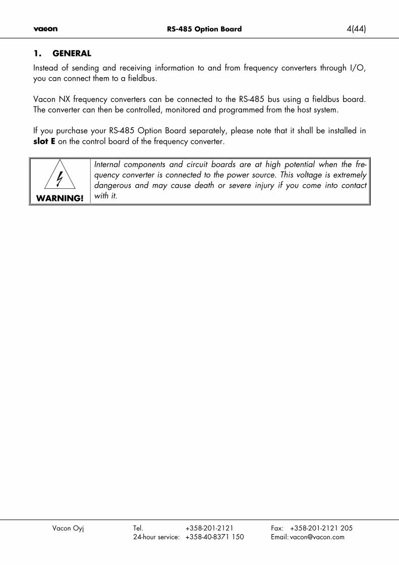
1. GENERAL
Instead of sending and receiving information to and from frequency converters through I/O,you can connect them to a fieldbus.
Vacon NX frequency converters can be connected to the RS-485 bus using a fieldbus board.The converter can then be controlled, monitored and programmed from the host system.
If you purchase your RS-485 Option Board separately, please note that it shall be installed inslot E on the control board of the frequency converter.
WARNING!
Internal components and circuit boards are at high potential when the fre-quency converter is connected to the power source. This voltage is extremelydangerous and may cause death or severe injury if you come into contactwith it.

RS-485 Option Board 5(44)
Vacon Oyj Tel. +358-201-2121 Fax: +358-201-2121 20524-hour service: +358-40-8371 150 Email: [email protected]
2. RS-485 OPTION BOARD TECHNICAL DATA
2.1 General
Interface NXOPTC2: Pluggable connector (5.08mm)NXOPTC8: 9-pin DSUB connector (female)
Data transfermethod
RS-485, half-duplex
Transfer cable Twisted pair (1 pair and shield)
Connections
Electrical isolation 500 VDCModbus RTUMetasys N2
As described in document “Modicon Modbus ProtocolReference Guide”Find it for example at: http://public.modicon.com/As described in Metasys N2 System Protocol Specifica-tion
Baud rate 300, 600, 1200, 2400, 4800, 9600, 19200 and38400 kbaud
Communications
Addresses 1 to 247Ambient operatingtemperature
–10°C…55°C
Storing temperature –40°C…60°CHumidity <95%, no condensation allowedAltitude Max. 1000 m
Environment
Vibration 0.5 G at 9…200 HzSafety Fulfils EN50178 standard
Table 1. RS-485 technical data
6(44) RS-485 Option Board
Vacon Oyj Tel. +358-201-2121 Fax: +358-201-2121 20524-hour service: +358-40-8371 150 Email: [email protected]
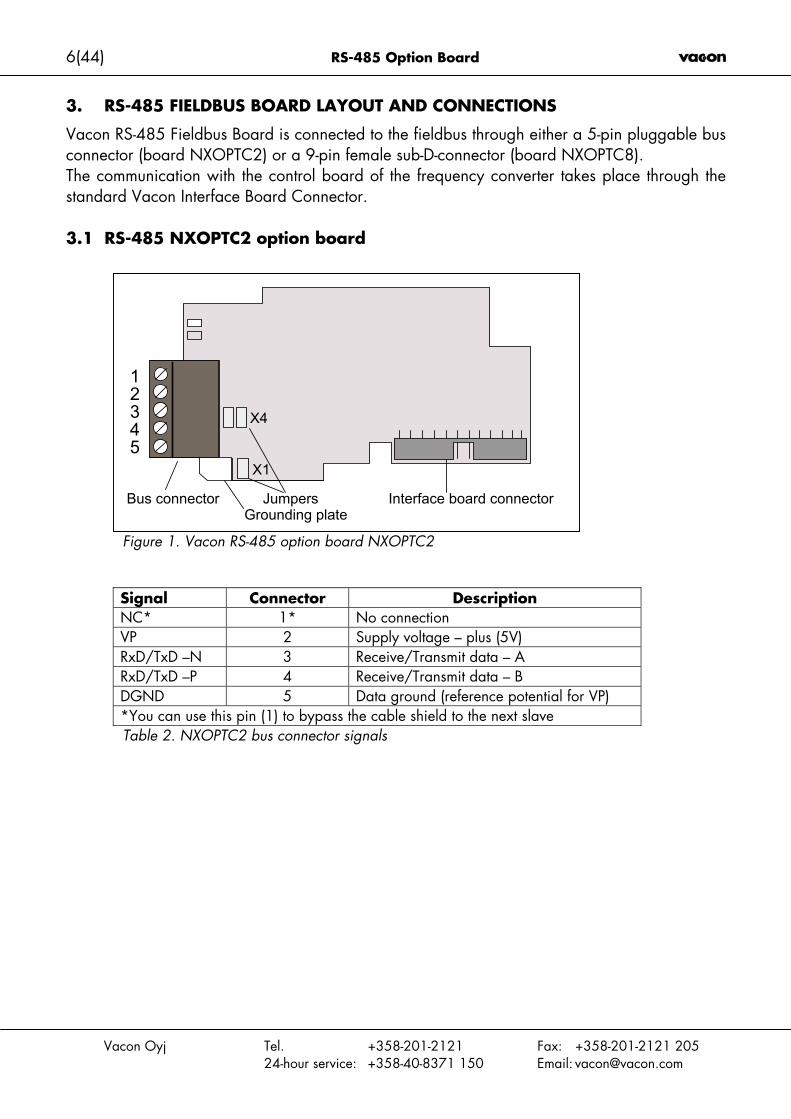
3. RS-485 FIELDBUS BOARD LAYOUT AND CONNECTIONS
Vacon RS-485 Fieldbus Board is connected to the fieldbus through either a 5-pin pluggable busconnector (board NXOPTC2) or a 9-pin female sub-D-connector (board NXOPTC8).The communication with the control board of the frequency converter takes place through thestandard Vacon Interface Board Connector.
3.1 RS-485 NXOPTC2 option board
Figure 1. Vacon RS-485 option board NXOPTC2
Signal Connector DescriptionNC* 1* No connectionVP 2 Supply voltage – plus (5V)RxD/TxD –N 3 Receive/Transmit data – ARxD/TxD –P 4 Receive/Transmit data – BDGND 5 Data ground (reference potential for VP)*You can use this pin (1) to bypass the cable shield to the next slaveTable 2. NXOPTC2 bus connector signals
X4
X1
Bus connector Jumpers Interface board connectorGrounding plate
12345

RS-485 Option Board 7(44)
Vacon Oyj Tel. +358-201-2121 Fax: +358-201-2121 20524-hour service: +358-40-8371 150 Email: [email protected]
3.2 RS-485 NXOPTC8 option board
Figure 2. Vacon RS-485 option board NXOPTC8
Signal Connector Description
Shield 1 Cable shieldRxD/TxD-N 3 Receive/ ADGND 5 Data ground (reference potential for VP)VP 6 Supply voltage – plus (5V)RxD/TxD-P 8 Receive/ Transmit data/ BTable 3. NXOPTC8 bus connector signals
X4
X1
Bus connector Jumpers Interface board connectorGrounding plate
12345
9 8 7 6

8(44) RS-485 Option Board
Vacon Oyj Tel. +358-201-2121 Fax: +358-201-2121 20524-hour service: +358-40-8371 150 Email: [email protected]
3.3 Grounding
3.3.1 Grounding by clamping the cable to the converter frame
This manner of grounding is the most effective and especially recommended when the dis-tances between the devices are relatively short or if the device is the last device on the net.
Note: Normally, the option board has already been installed in slot D or slot E of the controlboard. It is not necessary to detach the whole board for the grounding of the bus cable shield.Just detach the terminal block.
1 Strip about 5 cm of the cable and cut off the grey cable shield.Remember to do this for both bus cables (except for the last device). See pictures be-low.
2 Leave no more than 1 cm of the cable outside the terminal block and strip the datacables at about 0.5 cm to fit in the terminals. See pictures below.Note: Do this for both bus cables.
Figure 3.
Figure 4.
1 2 3 4 5
AB
Cut hereStrip this part

RS-485 Option Board 9(44)
Vacon Oyj Tel. +358-201-2121 Fax: +358-201-2121 20524-hour service: +358-40-8371 150 Email: [email protected]
3 Insert the data cables of both cables into terminals #3 (Line B) and #4 (Line A).
4 Strip the cable at such a distance from the terminal that you can fix it to the frame withthe grounding clamp. See
Figure 5.

10(44) RS-485 Option Board
Vacon Oyj Tel. +358-201-2121 Fax: +358-201-2121 20524-hour service: +358-40-8371 150 Email: [email protected]
3.3.2 Grounding only one point on the net
In this manner of grounding, the shield is connected to ground only at the last device on the netin the same way as described in chapter 3.3.1. Other devices of the net just pass the shield.We recommend you to use an Abico connector to fit the shields into the terminal.
1 Strip about 5 cm of the cable and cut off the grey cable shield. Remember to do thisfor both bus cables (except for the last device).
2 Leave no more than 1 cm of the cable outside the terminal block and strip the datacables at about 0.5 cm to fit in the terminals. See Figure 6.Note: Do this for both bus cables.
Figure 6.
3 Fix both the cables on the frame with the clamp. See Figure 7.
Figure 7.
1 2 3 4 5
ABShield
RS-485 Option Board 11(44)
Vacon Oyj Tel. +358-201-2121 Fax: +358-201-2121 20524-hour service: +358-40-8371 150 Email: [email protected]
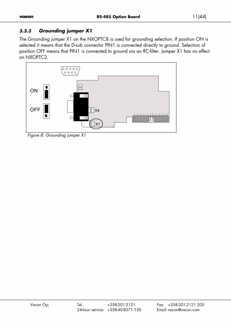
3.3.3 Grounding jumper X1
The Grounding jumper X1 on the NXOPTC8 is used for grounding selection. If position ON isselected it means that the D-sub connector PIN1 is connected directly to ground. Selection ofposition OFF means that PIN1 is connected to ground via an RC-filter. Jumper X1 has no effecton NXOPTC2.
Figure 8. Grounding jumper X1
X4
X1
ON
OFF
12345
9 8 7 6

12(44) RS-485 Option Board
Vacon Oyj Tel. +358-201-2121 Fax: +358-201-2121 20524-hour service: +358-40-8371 150 Email: [email protected]
3.4 Bus terminal resistors
If Vacon is the last device of the fieldbus line the bus termination must be set. Use jumper X4(ON position) or external termination resistors (e.g. in DSUB-9 connector). See Figure 9.
Figure 9. Using jumper X4 to set the bus termination.
X4
X1
12345
9 8 7 6
ON
OFF

RS-485 Option Board 13(44)
Vacon Oyj Tel. +358-201-2121 Fax: +358-201-2121 20524-hour service: +358-40-8371 150 Email: [email protected]
3.5 Bus Biasing
Bus biasing is required to ensure faultless communication between devices at RS-485 bus. Busbiasing makes sure that the bus state is at proper potential when no device is transmitting.Without biasing, faulty messages can be detected when the bus is in idle state. RS-485 busstate should be neather +0,200..+7V or –0,200..-7V. Illegal bus state is <200mV..-200mV.
Number of nodes Bias resistance2-5 1.8 kohm5-10 2.7 kohm11-20 12 kohm21-30 18 kohm31-40 27 kohm
Table 4. Bias resistor size vs number of node
Fail safe biasing in NXOPTC2 option boardConnect resistor biasing resistors between pins #2 and #4 as well as pins #3 and #5 asshown in picture.
Matters related to this are discussed in the application note Failsafe Biasing of DifferentialBuses (an-847.pdf) published by National Semiconductor (www.national.com).
DATA-
DATA+
5
1
2
3
4
5
14(44) RS-485 Option Board
Vacon Oyj Tel. +358-201-2121 Fax: +358-201-2121 20524-hour service: +358-40-8371 150 Email: [email protected]
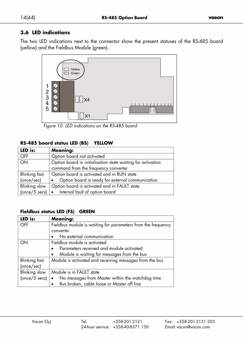
3.6 LED indications
The two LED indications next to the connector show the present statuses of the RS-485 board(yellow) and the Fieldbus Module (green).
Figure 10. LED indications on the RS-485 board
RS-485 board status LED (BS) YELLOWLED is: Meaning:OFF Option board not activatedON Option board in initialisation state waiting for activation
command from the frequency converterBlinking fast(once/sec)
Option board is activated and in RUN state• Option board is ready for external communication
Blinking slow(once/5 secs)
Option board is activated and in FAULT state• Internal fault of option board
Fieldbus status LED (FS) GREENLED is: Meaning:OFF Fieldbus module is waiting for parameters from the frequency
converter• No external communication
ON Fieldbus module is activated• Parameters received and module activated• Module is waiting for messages from the bus
Blinking fast(once/sec)
Module is activated and receiving messages from the bus
Blinking slow(once/5 secs)
Module is in FAULT state• No messages from Master within the watchdog time• Bus broken, cable loose or Master off line
X4
X1
12345
YellowGreen

RS-485 Option Board 15(44)
Vacon Oyj Tel. +358-201-2121 Fax: +358-201-2121 20524-hour service: +358-40-8371 150 Email: [email protected]
4. INSTALLATION OF VACON NX RS-485 BOARD
A Vacon NX frequency converter
B Remove the cable cover.
C Open the cover of the control unit.
16(44) RS-485 Option Board
Vacon Oyj Tel. +358-201-2121 Fax: +358-201-2121 20524-hour service: +358-40-8371 150 Email: [email protected]
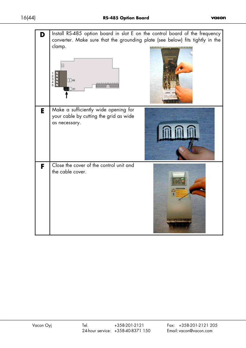
D Install RS-485 option board in slot E on the control board of the frequencyconverter. Make sure that the grounding plate (see below) fits tightly in theclamp.
E Make a sufficiently wide opening foryour cable by cutting the grid as wideas necessary.
F Close the cover of the control unit andthe cable cover.
X6
X1
12345

RS-485 Option Board 17(44)
Vacon Oyj Tel. +358-201-2121 Fax: +358-201-2121 20524-hour service: +358-40-8371 150 Email: [email protected]
5. COMMISSIONING
READ FIRST CHAPTER 8 'COMMISSIONING' IN VACON NX USER'S MANUAL (Documentnr. ud00701, please visit http://www.vacon.com/925.html).
Note! You must select Fieldbus as the active control place, if you wish to control the frequencyconverter through fieldbus. See Vacon NX User’s Manual, Chapter 7.3.3.1.
5.1 Fieldbus board parameters
The Vacon RS-485 board is commissioned with the control keypad by giving values to appro-priate parameters in menu M7 (for locating the expander board menu see Vacon NX User'sManual, Chapter 7).
Expander board menu (M7)The Expander board menu makes it possible for the user 1) to see what expander boards are connectedto the control board and 2) to reach and edit the parameters associated with the expander board.
Enter the following menu level (G#) with the Menu button right. At this level, you can browse throughslots A to E with the Browser buttons to see what expander boards are connected. On the lowermostline of the display you also see the number of parameter groups associated with the board.
If you still press the Menu button right once you will reach the parameter group level where there aretwo groups: Editable parameters and Monitored values. A further press on the Menu button right takesyou to either of these groups.
RS-485 parametersTo commission the RS-485 board, enter the level P7.5.1.# from the Parameters group (G7.5.1). Givedesired values to all RS-485 parameters (see Figure 11 and Table 5).
Figure 11. Changing the RS-485 board commissioning parameter values
Expander BoardG1 G5
READY
I/Oterm
NXOPTC5
READY
I/Oterm
G1 G2
Slave address
READY
I/Oterm
126 enter
CHANGE VALUE
CONFIRM CHANGE
Parameters
READY
I/Oterm
P1 P4
Slave address
READY
I/Oterm
126

18(44) RS-485 Option Board
Vacon Oyj Tel. +358-201-2121 Fax: +358-201-2121 20524-hour service: +358-40-8371 150 Email: [email protected]
# Name Default Range Description1 COMMUNICATION
PROTOCOL 1 1 – Modbus RTU2 – N2
Protocol
2 SLAVE ADDRESS 1 1…2473 BAUD RATE
6
1 – 300 baud2 – 600 baud3 – 1200 baud4 – 2400 baud5 – 4800 baud6 – 9600 baud7 – 19200 baud8 – 38400 baud
Communication speedWhen N2 protocol is used Baudrate mustbe set to 9600.
4 PARITY TYPE0
0 – None1 – Even2 – Odd
Describes what kind of parity checkingis used. When N2-protocol is used Paritytype must be set to 0 = None
5 COMMUNICATIONTIMEOUT
20 0—OFF1—300 s
See chapter Communication timeout be-low
6 OPERATE MODE 1 1 – Normal Reserved for later useTable 5. RS-485 parameters
The parameters of every device must be set before connecting to the bus. Especially the pa-rameters Communication Protocol, Slave Address and Baud Rate must be the same as in themaster configuration.
Communication timeoutThe RS-485 board initiates a communication error if communication is broken for as long as defined bythe Communication Timeout. Communication Timeout is disabled when given the value 0.
Communication statusTo see the present status of the RS-485 fieldbus, enter the Comm.Status page from Monitor menu(G7.5.2). See Figure 12 and Table 6 below.
Figure 12. Communication status
Monitor
READY
I/Oterm
V1 V1
READY
I/Oterm
0.841Comm. status
Error messagesGood messages

RS-485 Option Board 19(44)
Vacon Oyj Tel. +358-201-2121 Fax: +358-201-2121 20524-hour service: +358-40-8371 150 Email: [email protected]
Good messages0…999 Number of messages received without
communication errorsError messages
0…64 Number of messages received withCRC or parity errors
Table 6. RS-485 message indications
20(44) RS-485 Option Board
Vacon Oyj Tel. +358-201-2121 Fax: +358-201-2121 20524-hour service: +358-40-8371 150 Email: [email protected]
6. MODBUS
6.1 Modbus RTU protocol, introduction
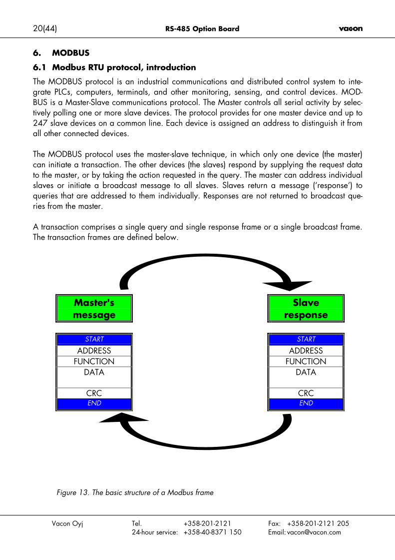
The MODBUS protocol is an industrial communications and distributed control system to inte-grate PLCs, computers, terminals, and other monitoring, sensing, and control devices. MOD-BUS is a Master-Slave communications protocol. The Master controls all serial activity by selec-tively polling one or more slave devices. The protocol provides for one master device and up to247 slave devices on a common line. Each device is assigned an address to distinguish it fromall other connected devices.
The MODBUS protocol uses the master-slave technique, in which only one device (the master)can initiate a transaction. The other devices (the slaves) respond by supplying the request datato the master, or by taking the action requested in the query. The master can address individualslaves or initiate a broadcast message to all slaves. Slaves return a message (‘response’) toqueries that are addressed to them individually. Responses are not returned to broadcast que-ries from the master.
A transaction comprises a single query and single response frame or a single broadcast frame.The transaction frames are defined below.
Master'smessage
Slaveresponse
START START
ADDRESS ADDRESSFUNCTION FUNCTION
DATA DATA
CRC CRCEND END
Figure 13. The basic structure of a Modbus frame
RS-485 Option Board 21(44)
Vacon Oyj Tel. +358-201-2121 Fax: +358-201-2121 20524-hour service: +358-40-8371 150 Email: [email protected]
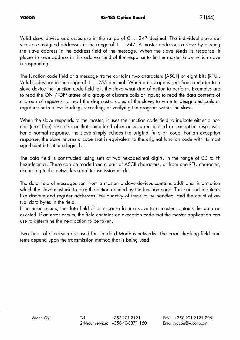
Valid slave device addresses are in the range of 0 ... 247 decimal. The individual slave de-vices are assigned addresses in the range of 1 ... 247. A master addresses a slave by placingthe slave address in the address field of the message. When the slave sends its response, itplaces its own address in this address field of the response to let the master know which slaveis responding.
The function code field of a message frame contains two characters (ASCII) or eight bits (RTU).Valid codes are in the range of 1 ... 255 decimal. When a message is sent from a master to aslave device the function code field tells the slave what kind of action to perform. Examples areto read the ON / OFF states of a group of discrete coils or inputs; to read the data contents ofa group of registers; to read the diagnostic status of the slave; to write to designated coils orregisters; or to allow loading, recording, or verifying the program within the slave.
When the slave responds to the master, it uses the function code field to indicate either a nor-mal (error-free) response or that some kind of error occurred (called an exception response).For a normal response, the slave simply echoes the original function code. For an exceptionresponse, the slave returns a code that is equivalent to the original function code with its mostsignificant bit set to a logic 1.
The data field is constructed using sets of two hexadecimal digits, in the range of 00 to FFhexadecimal. These can be made from a pair of ASCII characters, or from one RTU character,according to the network's serial transmission mode.
The data field of messages sent from a master to slave devices contains additional informationwhich the slave must use to take the action defined by the function code. This can include itemslike discrete and register addresses, the quantity of items to be handled, and the count of ac-tual data bytes in the field.If no error occurs, the data field of a response from a slave to a master contains the data re-quested. If an error occurs, the field contains an exception code that the master application canuse to determine the next action to be taken.
Two kinds of checksum are used for standard Modbus networks. The error checking field con-tents depend upon the transmission method that is being used.
22(44) RS-485 Option Board
Vacon Oyj Tel. +358-201-2121 Fax: +358-201-2121 20524-hour service: +358-40-8371 150 Email: [email protected]
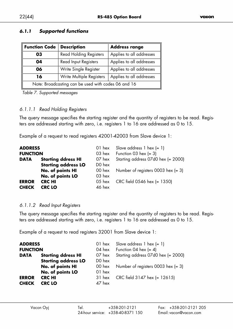
6.1.1 Supported functions
Function Code Description Address range
03 Read Holding Registers Applies to all addresses
04 Read Input Registers Applies to all addresses
06 Write Single Register Applies to all addresses
16 Write Multiple Registers Applies to all addresses
Note: Broadcasting can be used with codes 06 and 16
Table 7. Supported messages
6.1.1.1 Read Holding Registers
The query message specifies the starting register and the quantity of registers to be read. Regis-ters are addressed starting with zero, i.e. registers 1 to 16 are addressed as 0 to 15.
Example of a request to read registers 42001-42003 from Slave device 1:
ADDRESS 01 hex Slave address 1 hex (= 1)FUNCTION 03 hex Function 03 hex (= 3)
Starting ddress HI 07 hexStarting address LO D0 hex
Starting address 07d0 hex (= 2000)
No. of points HI 00 hex
DATA
No. of points LO 03 hexNumber of registers 0003 hex (= 3)
CRC HI 05 hexERRORCHECK CRC LO 46 hex
CRC field 0546 hex (= 1350)
6.1.1.2 Read Input Registers
The query message specifies the starting register and the quantity of registers to be read. Regis-ters are addressed starting with zero, i.e. registers 1 to 16 are addressed as 0 to 15.
Example of a request to read registers 32001 from Slave device 1:
ADDRESS 01 hex Slave address 1 hex (= 1)FUNCTION 04 hex Function 04 hex (= 4)
Starting ddress HI 07 hexStarting address LO D0 hex
Starting address 07d0 hex (= 2000)
No. of points HI 00 hex
DATA
No. of points LO 01 hexNumber of registers 0003 hex (= 3)
CRC HI 31 hexERRORCHECK CRC LO 47 hex
CRC field 3147 hex (= 12615)
RS-485 Option Board 23(44)
Vacon Oyj Tel. +358-201-2121 Fax: +358-201-2121 20524-hour service: +358-40-8371 150 Email: [email protected]
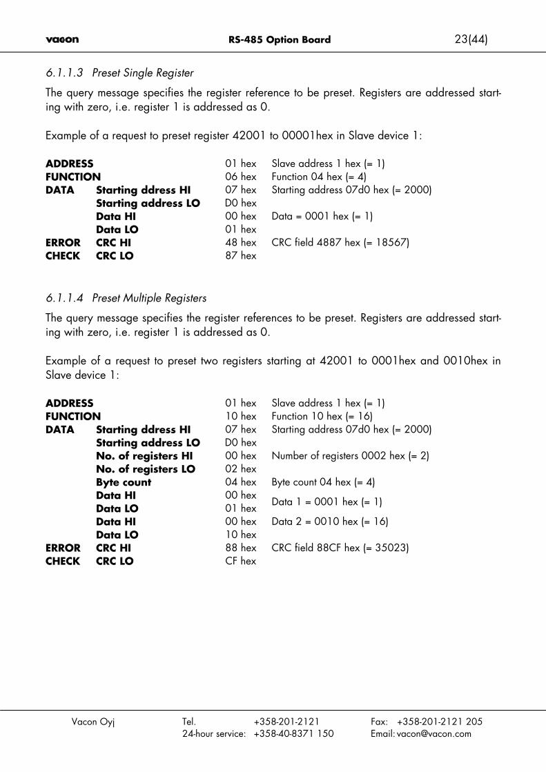
6.1.1.3 Preset Single Register
The query message specifies the register reference to be preset. Registers are addressed start-ing with zero, i.e. register 1 is addressed as 0.
Example of a request to preset register 42001 to 00001hex in Slave device 1:
ADDRESS 01 hex Slave address 1 hex (= 1)FUNCTION 06 hex Function 04 hex (= 4)
Starting ddress HI 07 hexStarting address LO D0 hex
Starting address 07d0 hex (= 2000)
Data HI 00 hex
DATA
Data LO 01 hexData = 0001 hex (= 1)
CRC HI 48 hexERRORCHECK CRC LO 87 hex
CRC field 4887 hex (= 18567)
6.1.1.4 Preset Multiple Registers
The query message specifies the register references to be preset. Registers are addressed start-ing with zero, i.e. register 1 is addressed as 0.
Example of a request to preset two registers starting at 42001 to 0001hex and 0010hex inSlave device 1:
ADDRESS 01 hex Slave address 1 hex (= 1)FUNCTION 10 hex Function 10 hex (= 16)
Starting ddress HI 07 hexStarting address LO D0 hex
Starting address 07d0 hex (= 2000)
No. of registers HI 00 hexNo. of registers LO 02 hex
Number of registers 0002 hex (= 2)
Byte count 04 hex Byte count 04 hex (= 4)Data HI 00 hexData LO 01 hex
Data 1 = 0001 hex (= 1)
Data HI 00 hex
DATA
Data LO 10 hexData 2 = 0010 hex (= 16)
CRC HI 88 hexERRORCHECK CRC LO CF hex
CRC field 88CF hex (= 35023)
24(44) RS-485 Option Board
Vacon Oyj Tel. +358-201-2121 Fax: +358-201-2121 20524-hour service: +358-40-8371 150 Email: [email protected]
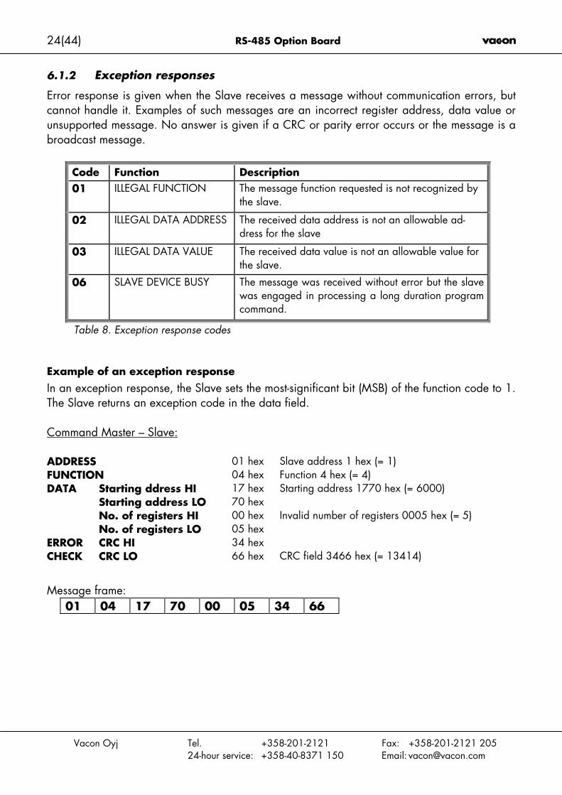
6.1.2 Exception responses
Error response is given when the Slave receives a message without communication errors, butcannot handle it. Examples of such messages are an incorrect register address, data value orunsupported message. No answer is given if a CRC or parity error occurs or the message is abroadcast message.
Code Function Description01 ILLEGAL FUNCTION The message function requested is not recognized by
the slave.
02 ILLEGAL DATA ADDRESS The received data address is not an allowable ad-dress for the slave
03 ILLEGAL DATA VALUE The received data value is not an allowable value forthe slave.
06 SLAVE DEVICE BUSY The message was received without error but the slavewas engaged in processing a long duration programcommand.
Table 8. Exception response codes
Example of an exception responseIn an exception response, the Slave sets the most-significant bit (MSB) of the function code to 1.The Slave returns an exception code in the data field.
Command Master – Slave:
ADDRESS 01 hex Slave address 1 hex (= 1)FUNCTION 04 hex Function 4 hex (= 4)
Starting ddress HI 17 hexStarting address LO 70 hex
Starting address 1770 hex (= 6000)
No. of registers HI 00 hex
DATA
No. of registers LO 05 hexInvalid number of registers 0005 hex (= 5)
CRC HI 34 hexERRORCHECK CRC LO 66 hex CRC field 3466 hex (= 13414)
Message frame:01 04 17 70 00 05 34 66

RS-485 Option Board 25(44)
Vacon Oyj Tel. +358-201-2121 Fax: +358-201-2121 20524-hour service: +358-40-8371 150 Email: [email protected]
Exception response.
Answer Slave – Master:
ADDRESS 01 hex Slave address 1 hex (= 1)FUNCTION 14 hex Most significant bit set to 1ERROR CODE 02 hex Error code 02 => Illegal Data Address
CRC HI AE hexERRORCHECK CRC LO C1 hex
CRC field AEC1 hex (= 44737)
Reply frame:01 14 02 AE C1

26(44) RS-485 Option Board
Vacon Oyj Tel. +358-201-2121 Fax: +358-201-2121 20524-hour service: +358-40-8371 150 Email: [email protected]
6.2 Modbus interface
Features of the Modbus-Vacon NX interface:• Direct control of Vacon NX ( e.g. Run, Stop, Direction, Speed reference, Fault reset)• Full access to all Vacon NX parameters• Monitor Vacon NX status (e.g. Output frequency, Output current, Fault code)
6.2.1 Modbus registers
The Vacon variables and fault codes as well as the parameters can be read and written fromModbus. The parameter addresses are determined in the application. Every parameter and ac-tual value have been given an ID number in the application. The ID numbering of the parame-ter as well as the parameter ranges and steps can be found in the application manual in ques-tion. The parameter value shall be given without decimals. If several parameters/actual valuesare read with one message, the adresses of the parameters/actual values must be consecutive.
All values can be read with function codes 3 and 4 (all registers are 3X and 4X reference).Modbus registers are mapped to drive ID’s as follows:
ID Modbus register Group R/W1 … 98 40001…40098 (30001…30098) Actual Values 30/199 40099 (30099) Fault Code 30/1101… 1999 40101…41999 (30101…31999) Parameters 30/12001…2099 42001…42099 (32001…32099) Process Data In 20/202101…2199 42101…42199 (32101…32199) Process Data Out 20/20Table 9. Index table
6.2.2 Process data
The process data fields are used to control the drive (e.g. Run, Stop , Reference, Fault Reset)and to quickly read actual values (e.g. Output frequency, Output current, Fault code). Thefields are structured as follows:
Process Data Slave -> Master (max 22 bytes)ID Modbus register Name Range/Type2101 32101, 42101 FB Status Word Binary coded2102 32102, 42102 FB General Status Word Binary coded2103 32103, 42103 FB Actual Speed 0…10000 %2104 32104, 42104 FB Process Data Out 1 See appendix 12105 32105, 42105 FB Process Data Out 2 See appendix 12106 32106, 42106 FB Process Data Out 3 See appendix 12107 32107, 42107 FB Process Data Out 4 See appendix 12108 32108, 42108 FB Process Data Out 5 See appendix 12109 32109, 42109 FB Process Data Out 6 See appendix 12110 32110, 42110 FB Process Data Out 7 See appendix 12111 32111, 42111 FB Process Data Out 8 See appendix 1Table 10.

RS-485 Option Board 27(44)
Vacon Oyj Tel. +358-201-2121 Fax: +358-201-2121 20524-hour service: +358-40-8371 150 Email: [email protected]
Process Data Master -> Slave (max 22 bytes)ID Modbus register Name Range/Type2001 32001, 42001 FB Control Word Binary coded2002 32002, 42002 FB General Control Word Binary coded2003 32003, 42003 FB Speed Reference 0…10000 %2004 32004, 42004 FB Process Data In 1 Integer 162005 32005, 42005 FB Process Data In 2 Integer 162006 32006, 42006 FB Process Data In 3 Integer 162007 32007, 42007 FB Process Data In 4 Integer 162008 32008, 42008 FB Process Data In 5 Integer 162009 32009, 42009 FB Process Data In 6 Integer 162010 32010, 42010 FB Process Data In 7 Integer 162011 32011, 42011 FB Process Data In 8 Integer 16Table 11.
The use of process data depends on the application. In a typical situation, the device is startedand stopped with the ControlWord (CW) written by the Master and the Rotating speed is setwith Reference (REF). With PD1…PD8 the device can be given other reference values (e.g.Torque reference). With the StatusWord (SW) read by the Master, the status of the device canbe seen. Actual Value (ACT) and PD1…PD8 show the other actual values.
6.2.3 Process data in
This register range is reserved for the control of the frequency converter. Process data in is lo-cated in range ID 2001…2099. The registers are updated every 10 ms. See Table 12.
ID Modbus register Name Range/Type2001 32001, 42001 FB Control Word Binary coded2002 32002, 42002 FB General Control Word Binary coded2003 32003, 42003 FB Speed Reference 0…10000 %2004 32004, 42004 FB Process Data In 1 Integer 162005 32005, 42005 FB Process Data In 2 Integer 162006 32006, 42006 FB Process Data In 3 Integer 162007 32007, 42007 FB Process Data In 4 Integer 162008 32008, 42008 FB Process Data In 5 Integer 162009 32009, 42009 FB Process Data In 6 Integer 162010 32010, 42010 FB Process Data In 7 Integer 162011 32011, 42011 FB Process Data In 8 Integer 16Table 12. Fieldbus basic input table
28(44) RS-485 Option Board
Vacon Oyj Tel. +358-201-2121 Fax: +358-201-2121 20524-hour service: +358-40-8371 150 Email: [email protected]
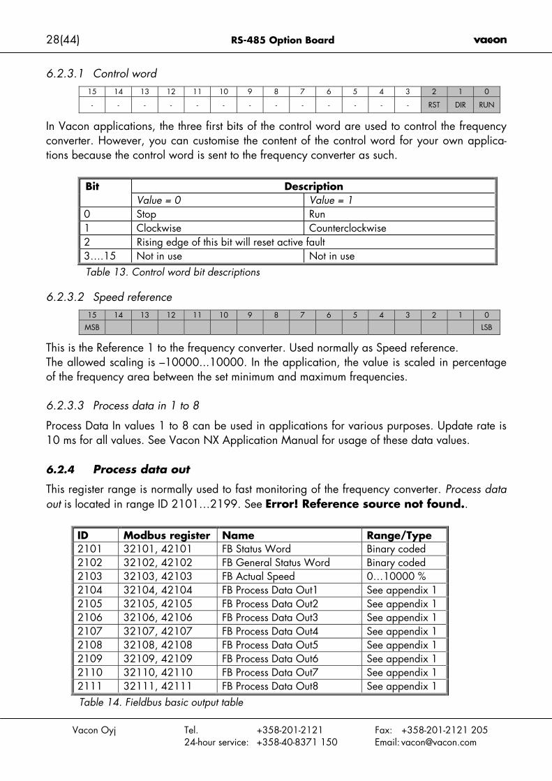
6.2.3.1 Control word15 14 13 12 11 10 9 8 7 6 5 4 3 2 1 0
- - - - - - - - - - - - - RST DIR RUN
In Vacon applications, the three first bits of the control word are used to control the frequencyconverter. However, you can customise the content of the control word for your own applica-tions because the control word is sent to the frequency converter as such.
DescriptionBitValue = 0 Value = 1
0 Stop Run1 Clockwise Counterclockwise2 Rising edge of this bit will reset active fault3….15 Not in use Not in useTable 13. Control word bit descriptions
6.2.3.2 Speed reference15 14 13 12 11 10 9 8 7 6 5 4 3 2 1 0
MSB LSB
This is the Reference 1 to the frequency converter. Used normally as Speed reference.The allowed scaling is –10000...10000. In the application, the value is scaled in percentageof the frequency area between the set minimum and maximum frequencies.
6.2.3.3 Process data in 1 to 8
Process Data In values 1 to 8 can be used in applications for various purposes. Update rate is10 ms for all values. See Vacon NX Application Manual for usage of these data values.
6.2.4 Process data out
This register range is normally used to fast monitoring of the frequency converter. Process dataout is located in range ID 2101…2199. See Error! Reference source not found..
ID Modbus register Name Range/Type2101 32101, 42101 FB Status Word Binary coded2102 32102, 42102 FB General Status Word Binary coded2103 32103, 42103 FB Actual Speed 0…10000 %2104 32104, 42104 FB Process Data Out1 See appendix 12105 32105, 42105 FB Process Data Out2 See appendix 12106 32106, 42106 FB Process Data Out3 See appendix 12107 32107, 42107 FB Process Data Out4 See appendix 12108 32108, 42108 FB Process Data Out5 See appendix 12109 32109, 42109 FB Process Data Out6 See appendix 12110 32110, 42110 FB Process Data Out7 See appendix 12111 32111, 42111 FB Process Data Out8 See appendix 1Table 14. Fieldbus basic output table
RS-485 Option Board 29(44)
Vacon Oyj Tel. +358-201-2121 Fax: +358-201-2121 20524-hour service: +358-40-8371 150 Email: [email protected]
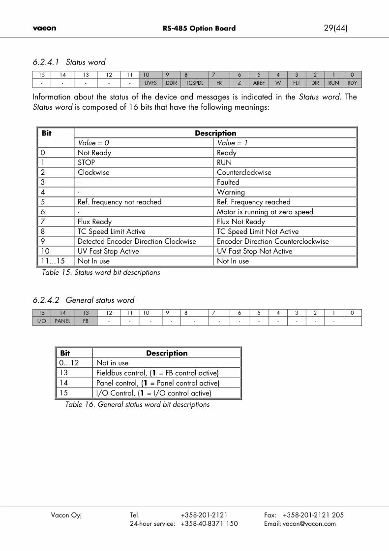
6.2.4.1 Status word15 14 13 12 11 10 9 8 7 6 5 4 3 2 1 0- - - - - UVFS DDIR TCSPDL FR Z AREF W FLT DIR RUN RDY
Information about the status of the device and messages is indicated in the Status word. TheStatus word is composed of 16 bits that have the following meanings:
DescriptionBitValue = 0 Value = 1
0 Not Ready Ready1 STOP RUN2 Clockwise Counterclockwise3 - Faulted4 - Warning5 Ref. frequency not reached Ref. Frequency reached6 - Motor is running at zero speed7 Flux Ready Flux Not Ready8 TC Speed Limit Active TC Speed Limit Not Active9 Detected Encoder Direction Clockwise Encoder Direction Counterclockwise10 UV Fast Stop Active UV Fast Stop Not Active11...15 Not In use Not In useTable 15. Status word bit descriptions
6.2.4.2 General status word15 14 13 12 11 10 9 8 7 6 5 4 3 2 1 0I/O PANEL FB - - - - - - - - - - - -
Bit Description0...12 Not in use13 Fieldbus control, (1 = FB control active)14 Panel control, (1 = Panel control active)15 I/O Control, (1 = I/O control active)
Table 16. General status word bit descriptions
30(44) RS-485 Option Board
Vacon Oyj Tel. +358-201-2121 Fax: +358-201-2121 20524-hour service: +358-40-8371 150 Email: [email protected]
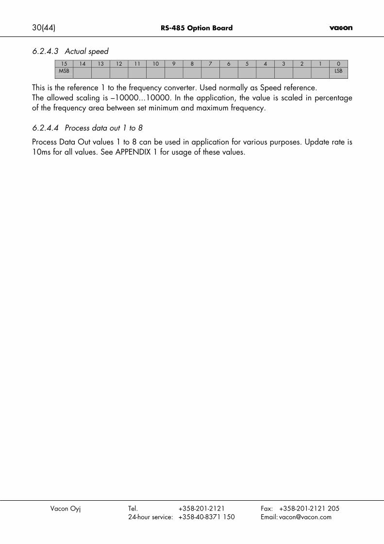
6.2.4.3 Actual speed15 14 13 12 11 10 9 8 7 6 5 4 3 2 1 0
MSB LSB
This is the reference 1 to the frequency converter. Used normally as Speed reference.The allowed scaling is –10000...10000. In the application, the value is scaled in percentageof the frequency area between set minimum and maximum frequency.
6.2.4.4 Process data out 1 to 8
Process Data Out values 1 to 8 can be used in application for various purposes. Update rate is10ms for all values. See APPENDIX 1 for usage of these values.
RS-485 Option Board 31(44)
Vacon Oyj Tel. +358-201-2121 Fax: +358-201-2121 20524-hour service: +358-40-8371 150 Email: [email protected]
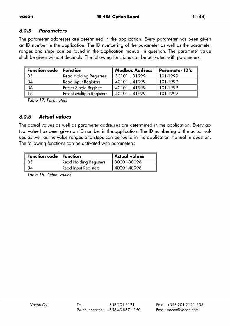
6.2.5 Parameters
The parameter addresses are determined in the application. Every parameter has been givenan ID number in the application. The ID numbering of the parameter as well as the parameterranges and steps can be found in the application manual in question. The parameter valueshall be given without decimals. The following functions can be activated with parameters:
Function code Function Modbus Address Parameter ID’s03 Read Holding Registers 30101…31999 101-199904 Read Input Registers 40101…41999 101-199906 Preset Single Register 40101…41999 101-199916 Preset Multiple Registers 40101…41999 101-1999Table 17. Parameters
6.2.6 Actual values
The actual values as well as parameter addresses are determined in the application. Every ac-tual value has been given an ID number in the application. The ID numbering of the actual val-ues as well as the value ranges and steps can be found in the application manual in question.The following functions can be activated with parameters:
Function code Function Actual values03 Read Holding Registers 30001-3009804 Read Input Registers 40001-40098Table 18. Actual values
32(44) RS-485 Option Board
Vacon Oyj Tel. +358-201-2121 Fax: +358-201-2121 20524-hour service: +358-40-8371 150 Email: [email protected]
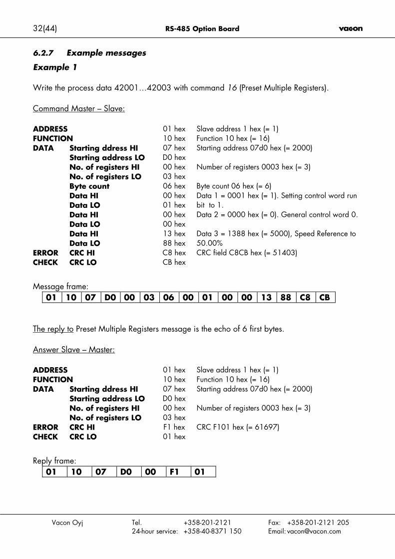
6.2.7 Example messages
Example 1
Write the process data 42001…42003 with command 16 (Preset Multiple Registers).
Command Master – Slave:
ADDRESS 01 hex Slave address 1 hex (= 1)FUNCTION 10 hex Function 10 hex (= 16)
Starting ddress HI 07 hexStarting address LO D0 hex
Starting address 07d0 hex (= 2000)
No. of registers HI 00 hexNo. of registers LO 03 hex
Number of registers 0003 hex (= 3)
Byte count 06 hex Byte count 06 hex (= 6)Data HI 00 hexData LO 01 hex
Data 1 = 0001 hex (= 1). Setting control word runbit to 1.
Data HI 00 hexData LO 00 hex
Data 2 = 0000 hex (= 0). General control word 0.
Data HI 13 hex
DATA
Data LO 88 hexData 3 = 1388 hex (= 5000), Speed Reference to50.00%
CRC HI C8 hexERRORCHECK CRC LO CB hex
CRC field C8CB hex (= 51403)
Message frame:01 10 07 D0 00 03 06 00 01 00 00 13 88 C8 CB
The reply to Preset Multiple Registers message is the echo of 6 first bytes.
Answer Slave – Master:
ADDRESS 01 hex Slave address 1 hex (= 1)FUNCTION 10 hex Function 10 hex (= 16)
Starting ddress HI 07 hexStarting address LO D0 hex
Starting address 07d0 hex (= 2000)
No. of registers HI 00 hex
DATA
No. of registers LO 03 hexNumber of registers 0003 hex (= 3)
CRC HI F1 hexERRORCHECK CRC LO 01 hex
CRC F101 hex (= 61697)
Reply frame:01 10 07 D0 00 F1 01

RS-485 Option Board 33(44)
Vacon Oyj Tel. +358-201-2121 Fax: +358-201-2121 20524-hour service: +358-40-8371 150 Email: [email protected]
Example 2
Read the Process Data 42103…42104 with command 4 (Read Input Registers).
Command Master – Slave:
ADDRESS 01 hex Slave address 1 hex (= 1)FUNCTION 04 hex Function 4 hex (= 4)
Starting ddress HI 08 hexStarting address LO 36 hex
Starting address 0836 hex (= 2102)
No. of registers HI 00 hex
DATA
No. of registers LO 02 hexNumber of registers 0002 hex (= 2)
CRC HI 93 hexERRORCHECK CRC LO A5 hex CRC field B321 hex (= 45857)
Message frame:01 04 08 36 00 02 93 A5
The reply to the Read Input Registers message contains the values of the read registers.
Answer Slave – Master:
ADDRESS 01 hex Slave address 1 hex (= 1)FUNCTION 04 hex Function 4 hex (= 4)
Byte count 02 hex Byte count 4 hex (= 4)Data HI 13 hexData LO 88 hex
Speed reference = 1388 hex (=5000 => 50.00%)
Data HI 09 hex
DATA
Data LO C4 hexOutput Frequency = 09C4 hex (=2500 =>25.00Hz)
CRC HI F0 hexERRORCHECK CRC LO E9 hex
CRC field B321 hex (= 45857)
Reply frame:01 04 02 13 88 09 C4 F0 E9

34(44) RS-485 Option Board
Vacon Oyj Tel. +358-201-2121 Fax: +358-201-2121 20524-hour service: +358-40-8371 150 Email: [email protected]
6.3 Start-up test
Frequency converter applicationChoose Fieldbus (Bus/Comm) as the active control place (see Vacon NX User's Manual, Chap-ter 7.3.3).
Master software
1. Set FB Control Word (MBaddr 42001) value to 1hex.
2. Frequency converter status is RUN.
3. Set FB Speed Reference (MBaddr 42003) value to 5000 (=50,00%).
4. The Actual value is 5000 and the frequency converter output frequency is 25,00 Hz.
5. Set FB Control Word (MBaddr 42001) value to 0hex.
6. Frequency converter status is STOP.
If FB Status Word (Addr 42101) bit 3 = 1 Status of frequency converter is FAULT.
RS-485 Option Board 35(44)
Vacon Oyj Tel. +358-201-2121 Fax: +358-201-2121 20524-hour service: +358-40-8371 150 Email: [email protected]
7. METASYS N2
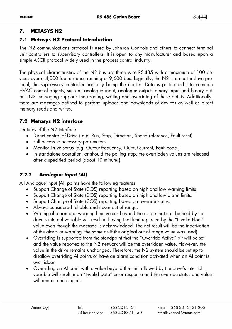
7.1 Metasys N2 Protocol Introduction
The N2 communications protocol is used by Johnson Controls and others to connect terminalunit controllers to supervisory controllers. It is open to any manufacturer and based upon asimple ASCII protocol widely used in the process control industry.
The physical characteristics of the N2 bus are three wire RS-485 with a maximum of 100 de-vices over a 4,000 foot distance running at 9,600 bps. Logically, the N2 is a master-slave pro-tocol, the supervisory controller normally being the master. Data is partitioned into commonHVAC control objects, such as analogue input, analogue output, binary input and binary out-put. N2 messaging supports the reading, writing and overriding of these points. Additionally,there are messages defined to perform uploads and downloads of devices as well as directmemory reads and writes.
7.2 Metasys N2 interface
Features of the N2 Interface:• Direct control of Drive ( e.g. Run, Stop, Direction, Speed reference, Fault reset)• Full access to necessary parameters• Monitor Drive status (e.g. Output frequency, Output current, Fault code )• In standalone operation, or should the polling stop, the overridden values are released
after a specified period (about 10 minutes).
7.2.1 Analogue Input (AI)
All Analogue Input (AI) points have the following features:• Support Change of State (COS) reporting based on high and low warning limits.• Support Change of State (COS) reporting based on high and low alarm limits.• Support Change of State (COS) reporting based on override status.• Always considered reliable and never out of range.• Writing of alarm and warning limit values beyond the range that can be held by the
drive’s internal variable will result in having that limit replaced by the “Invalid Float”value even though the message is acknowledged. The net result will be the inactivationof the alarm or warning (the same as if the original out of range value was used).
• Overriding is supported from the standpoint that the “Override Active” bit will be setand the value reported to the N2 network will be the overridden value. However, thevalue in the drive remains unchanged. Therefore, the N2 system should be set up todisallow overriding AI points or have an alarm condition activated when an AI point isoverridden.
• Overriding an AI point with a value beyond the limit allowed by the drive’s internalvariable will result in an “Invalid Data” error response and the override status and valuewill remain unchanged.
36(44) RS-485 Option Board
Vacon Oyj Tel. +358-201-2121 Fax: +358-201-2121 20524-hour service: +358-40-8371 150 Email: [email protected]
7.2.2 Binary Input (BI)
All Binary Input (BI) points have the following features:• Support Change of State (COS) reporting based on current state.• Support Change of State (COS) reporting based on alarm condition.• Support Change of State (COS) reporting based on override status.• Always considered reliable.
Overriding is supported from the standpoint that the “Override Active” bit will be set and thevalue reported to the N2 network will be the overridden value. However, the value in the driveremains unchanged. Therefore, the N2 system should be set up to disallow overriding BI pointsor have an alarm condition activated when a BI point is overridden.
7.2.3 Analogue Output (AO)
All Analogue Output (AO) points have the following features:• Support Change of State (COS) reporting based on override status.• Always considered reliable.• Overriding of the AO points is the method used to change a value. Overriding an AO
point with a value beyond the limit allowed by the drive’s internal variable will result inan ”Invalid Data” error response and the override status and value will remain un-changed. If the overridden value is beyond the drive’s parameter limit but within therange that will fit in the variable, an acknowledge response is given and the value willbe internally clamped to its limit.
• An AO point override copies the override value to the corresponding drive parameter.This is the same as changing the value on the keypad. The value is non-volatile and willremain in effect when the drive is turned off and back on. It also remains at this valuewhen the N2 network "releases" the point. The N2 system always reads the current pa-rameter value.
Note:On some N2 systems, the system will not poll the AO point when it is being overridden. In thiscase, the N2 system will not notice a change in value if the change is made with the keypad.To avoid this, set the point up as a ”local control” type and release it once it has been overrid-den. In this way, the N2 system will monitor the value when not being overridden.
7.2.4 Binary Output (BO)
All Binary Output (BO) points have the follwoing features:• Support Change of State (COS) reporting based on override status.• Always considered reliable.• Overriding BO points control the drive. These points are input commands to the drive.
When released, the drive's internal value remains at its last overridden value.

RS-485 Option Board 37(44)
Vacon Oyj Tel. +358-201-2121 Fax: +358-201-2121 20524-hour service: +358-40-8371 150 Email: [email protected]
7.2.5 Internal Integer (ADI)
All Internal Integer (ADI) points have the follwoing features:• Do not support Change of State (COS) reporting.• Can be overridden and the ”Override Active” bit will be set. However, the Internal
value is unchanged (Read Only).
38(44) RS-485 Option Board
Vacon Oyj Tel. +358-201-2121 Fax: +358-201-2121 20524-hour service: +358-40-8371 150 Email: [email protected]
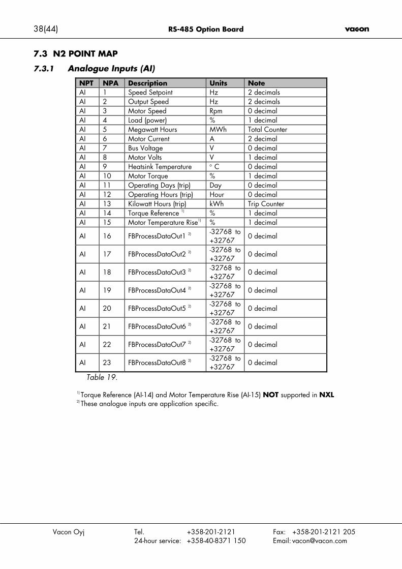
7.3 N2 POINT MAP
7.3.1 Analogue Inputs (AI)
NPT NPA Description Units NoteAI 1 Speed Setpoint Hz 2 decimalsAI 2 Output Speed Hz 2 decimalsAI 3 Motor Speed Rpm 0 decimalAI 4 Load (power) % 1 decimalAI 5 Megawatt Hours MWh Total CounterAI 6 Motor Current A 2 decimalAI 7 Bus Voltage V 0 decimalAI 8 Motor Volts V 1 decimalAI 9 Heatsink Temperature ° C 0 decimalAI 10 Motor Torque % 1 decimalAI 11 Operating Days (trip) Day 0 decimalAI 12 Operating Hours (trip) Hour 0 decimalAI 13 Kilowatt Hours (trip) kWh Trip CounterAI 14 Torque Reference 1) % 1 decimalAI 15 Motor Temperature Rise1) % 1 decimal
AI 16 FBProcessDataOut1 2) -32768 to+32767
0 decimal
AI 17 FBProcessDataOut2 2) -32768 to+32767 0 decimal
AI 18 FBProcessDataOut3 2) -32768 to+32767
0 decimal
AI 19 FBProcessDataOut4 2) -32768 to+32767 0 decimal
AI 20 FBProcessDataOut5 2) -32768 to+32767
0 decimal
AI 21 FBProcessDataOut6 2) -32768 to+32767 0 decimal
AI 22 FBProcessDataOut7 2) -32768 to+32767
0 decimal
AI 23 FBProcessDataOut8 2) -32768 to+32767 0 decimal
Table 19.
1) Torque Reference (AI-14) and Motor Temperature Rise (AI-15) NOT supported in NXL2) These analogue inputs are application specific.

RS-485 Option Board 39(44)
Vacon Oyj Tel. +358-201-2121 Fax: +358-201-2121 20524-hour service: +358-40-8371 150 Email: [email protected]
7.3.2 Binary Inputs (BI)
NPT NPA Description 0 = 1 =BI 1 Ready Not Ready ReadyBI 2 Run Stop RunBI 3 Direction Clockwise CounterclockwiseBI 4 Faulted Not Faulted FaultedBI 5 Warning Not Warning WarningBI 6 Ref. Frequency reached False TrueBI 7 Motor running zero speed False TrueBI 8 General 0 3) 0 1BI 9 General 1 3) 0 1BI 10 General 2 3) 0 1BI 11 General 3 3) 0 1BI 12 General 4 3) 0 1BI 13 General 5 3) 0 1BI 14 General 6 3) 0 1BI 15 General 7 3) 0 1
Table 20.
3) These binary inputs are application specific. They are read from the drives General Status Word.
7.3.3 Analogue Outputs (AO)
NPT NPA Description Units NoteAO 1 Comms Speed % 2 decimalsAO 2 Current Limit A 2 decimals
AO 3 Minimum Speed Hz 2 decimalsAO 4 Maximum Speed Hz 2 decimalsAO 5 Accel Time s 1 decimalAO 6 Decel Time s 1 decimalAO 7 FBProcessDataIN 1 4) -32768 to +32767 2 decimalsAO 8 FBProcessDataIN 2 4) -32768 to +32767 2 decimalsAO 9 FBProcessDataIN 3 4) -32768 to +32767 2 decimalsAO 10 FBProcessDataIN 4 4) -32768 to +32767 2 decimals
Table 21.
4) These Analogue Outputs are application specific.

40(44) RS-485 Option Board
Vacon Oyj Tel. +358-201-2121 Fax: +358-201-2121 20524-hour service: +358-40-8371 150 Email: [email protected]
7.3.4 Binary Outputs (BO)
NPT NPA Description 0 = 1 =BO 1 Comms Start/Stop Stop StartBO 2 Comms Forward/Reverse Forward ReverseBO 3 Reset Fault N/A ResetBO 4 FBFixedControlWord Bit_3 5) - -BO 5 FBFixedControlWord Bit_4 5) - -BO 6 FBFixedControlWord Bit_5 5) - -BO 7 FBFixedControlWord Bit_6 5) - -BO 8 FBFixedControlWord Bit_7 5) - -BO 9 FBFixedControlWord Bit_8 5) - -BO 10 FBFixedControlWord Bit_9 5) - -BO 11 FBFixedControlWord Bit_10 5) - -BO 12 FBFixedControlWord Bit_11 5) - -BO 13 FBFixedControlWord Bit_12 5) - -BO 14 FBFixedControlWord Bit_13 5) - -BO 15 FBFixedControlWord Bit_14 5) - -BO 16 FBFixedControlWord Bit_15 5) - -Table 22.
5) These Binary Outputs are application specific.
7.3.5 Internal Integers (ADI)
NPT NPA Description UnitsADI 1 Active Fault Code - Table 23.
RS-485 Option Board 41(44)
Vacon Oyj Tel. +358-201-2121 Fax: +358-201-2121 20524-hour service: +358-40-8371 150 Email: [email protected]
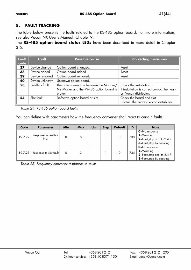
8. FAULT TRACKING
The table below presents the faults related to the RS-485 option board. For more information,see also Vacon NX User's Manual, Chapter 9.The RS-485 option board status LEDs have been described in more detail in Chapter3.6.
Faultcode
Fault Possible cause Correcting measures
37 Device change Option board changed. Reset38 Device added Option board added. Reset39 Device removed Option board removed. Reset40 Device unknown Unknown option board.53 Fieldbus fault The data connection between the Modbus/
N2 Master and the RS-485 option board isbroken
Check the installation.If installation is correct contact the near-est Vacon distributor.
54 Slot fault Defective option board or slot Check the board and slot.Contact the nearest Vacon distributor.
Table 24. RS-485 option board faults
You can define with parameters how the frequency converter shall react to certain faults:
Code Parameter Min Max Unit Step Default ID Note
P2.7.22Response to fieldbus
fault 0 3 1 0 733
0=No response1=Warning2=Fault,stop acc. to 2.4.73=Fault,stop by coasting
P2.7.23 Response to slot fault 0 3 1 0 734
0=No response1=Warning2=Fault,stop acc. to 2.4.73=Fault,stop by coasting
Table 25. Frequency converter responses to faults
42(44) RS-485 Option Board
Vacon Oyj Tel. +358-201-2121 Fax: +358-201-2121 20524-hour service: +358-40-8371 150 Email: [email protected]
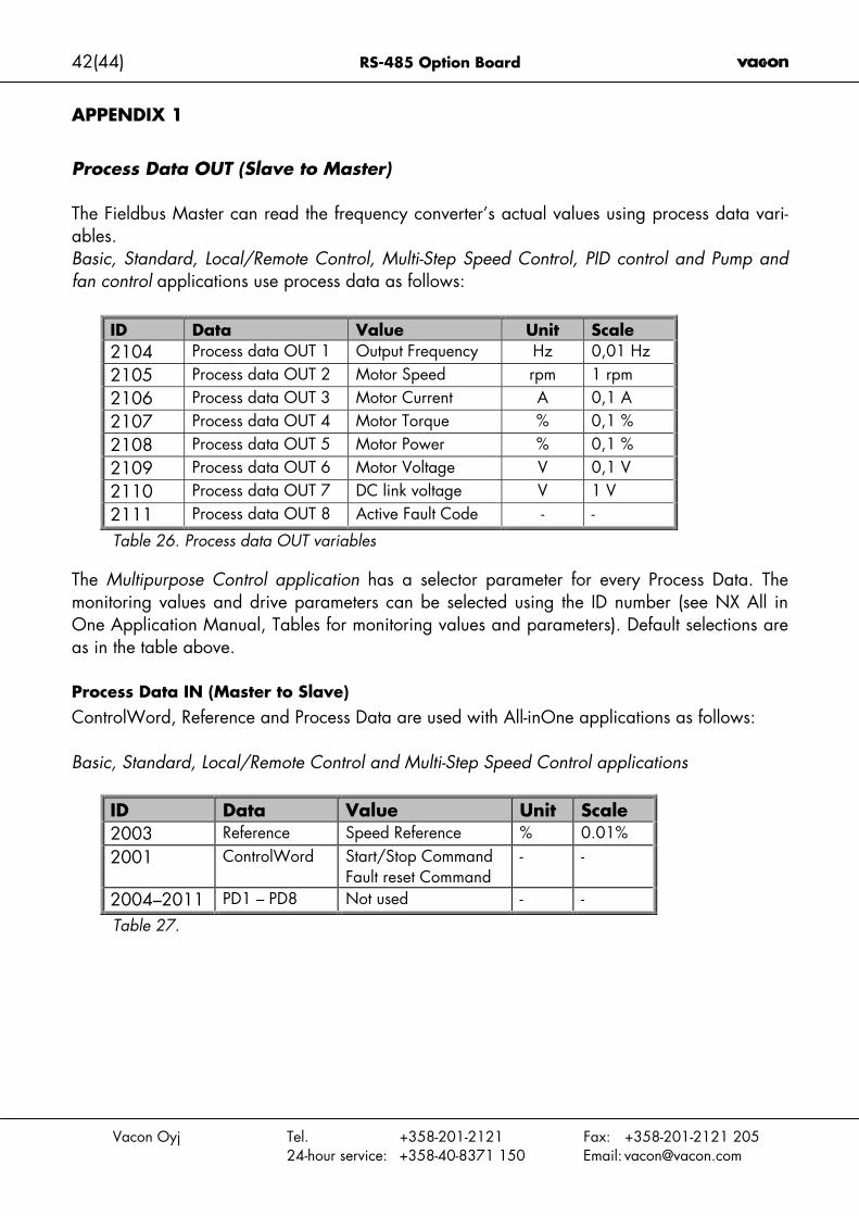
APPENDIX 1
Process Data OUT (Slave to Master)
The Fieldbus Master can read the frequency converter’s actual values using process data vari-ables.Basic, Standard, Local/Remote Control, Multi-Step Speed Control, PID control and Pump andfan control applications use process data as follows:
ID Data Value Unit Scale2104 Process data OUT 1 Output Frequency Hz 0,01 Hz2105 Process data OUT 2 Motor Speed rpm 1 rpm2106 Process data OUT 3 Motor Current A 0,1 A2107 Process data OUT 4 Motor Torque % 0,1 %2108 Process data OUT 5 Motor Power % 0,1 %2109 Process data OUT 6 Motor Voltage V 0,1 V2110 Process data OUT 7 DC link voltage V 1 V2111 Process data OUT 8 Active Fault Code - -
Table 26. Process data OUT variables
The Multipurpose Control application has a selector parameter for every Process Data. Themonitoring values and drive parameters can be selected using the ID number (see NX All inOne Application Manual, Tables for monitoring values and parameters). Default selections areas in the table above.
Process Data IN (Master to Slave)ControlWord, Reference and Process Data are used with All-inOne applications as follows:
Basic, Standard, Local/Remote Control and Multi-Step Speed Control applications
ID Data Value Unit Scale2003 Reference Speed Reference % 0.01%2001 ControlWord Start/Stop Command
Fault reset Command- -
2004–2011 PD1 – PD8 Not used - -
Table 27.

RS-485 Option Board 43(44)
Vacon Oyj Tel. +358-201-2121 Fax: +358-201-2121 20524-hour service: +358-40-8371 150 Email: [email protected]
Multipurpose Control application
ID Data Value Unit Scale2003 Reference Speed Reference % 0.01%2001 ControlWord Start/Stop Command
Fault reset Command- -
2004 Process Data IN1 Torque Reference % 0.1%2005 Process Data IN2 Free Analogia INPUT % 0.01%2006–2011 PD3 – PD8 Not Used - -
Table 28.
PID control and Pump and fan control applications
ID Data Value Unit Scale2003 Reference Speed Reference % 0.01%2001 ControlWord Start/Stop Command
Fault reset Command- -
2004 Process Data IN1 Reference for PID con-troller
% 0.01%
2005 Process Data IN2 Actual Value 1 to PIDcontroller
% 0.01%
2006 Process Data IN3 Actual Value 2 to PIDcontroller
% 0.01%
2007–2011 PD4–PD8 Not Used - -
Table 29

Vacon PlcP.O.Box 25
Runsorintie 765381 VAASA
FINLANDTel: +358-(0)201-2121
Fax: +358-(0)201-212 20524-hour service: +358-(0)40-8371 150
E-mail: [email protected]
ud97
2.do
c10
.3.2
004
14:4
6