user’s manual - sportsmith.netnordictrack... · how to order replacement parts ... slide the...
TRANSCRIPT

CAUTIONRead all precautions and instruc-tions in this manual before usingthis equipment. Keep this manualfor future reference.
Model No. NTE99021Serial No. _
Serial NumberDecal
QUESTIONS?If you have questions, or if thereare missing parts, we will guar-antee complete satisfactionthrough direct assistance fromour factory.
TO AVOID DELAYS, PLEASECALL DIRECT TO OUR TOLL-FREE CUSTOMER HOT LINE. Thetrained technicians on our cus-tomer hot line will provide imme-diate assistance, free of charge toyou.
CUSTOMER HOT LINE:
1-888-825-2588Mon.–Fri., 6 a.m.–6 p.m. MST
Visit our website at
www.nordictrack.comnew products, prizes,
fitness tips, and much more!
USER’S MANUAL

TABLE OF CONTENTS
IMPORTANT PRECAUTIONS . . . . . . . . . . . . . . . . . . . . . . . . . . . . . . . . . . . . . . . . . . . . . . . . . . . . . . . . . . . . .3BEFORE YOU BEGIN . . . . . . . . . . . . . . . . . . . . . . . . . . . . . . . . . . . . . . . . . . . . . . . . . . . . . . . . . . . . . . . . . . .4ASSEMBLY . . . . . . . . . . . . . . . . . . . . . . . . . . . . . . . . . . . . . . . . . . . . . . . . . . . . . . . . . . . . . . . . . . . . . . . . . . .5HOW TO USE THE ELLIPTICAL CROSSTRAINER . . . . . . . . . . . . . . . . . . . . . . . . . . . . . . . . . . . . . . . . . . . . .8MAINTENANCE AND TROUBLESHOOTING . . . . . . . . . . . . . . . . . . . . . . . . . . . . . . . . . . . . . . . . . . . . . . . . .20CONDITIONING GUIDELINES . . . . . . . . . . . . . . . . . . . . . . . . . . . . . . . . . . . . . . . . . . . . . . . . . . . . . . . . . . . .21PART LIST . . . . . . . . . . . . . . . . . . . . . . . . . . . . . . . . . . . . . . . . . . . . . . . . . . . . . . . . . . . . . . . . . . . . . . . . . . .22EXPLODED DRAWING . . . . . . . . . . . . . . . . . . . . . . . . . . . . . . . . . . . . . . . . . . . . . . . . . . . . . . . . . . . . . . . . .23HOW TO ORDER REPLACEMENT PARTS . . . . . . . . . . . . . . . . . . . . . . . . . . . . . . . . . . . . . . . . . . .Back CoverLIMITED WARRANTY . . . . . . . . . . . . . . . . . . . . . . . . . . . . . . . . . . . . . . . . . . . . . . . . . . . . . . . . . . .Back Cover
2
NordicTrack is a registered trademark of ICON Health & Fitness, Inc.

3
IMPORTANT PRECAUTIONSWARNING: To reduce the risk of serious injury, read the following important precau-
tions before using the elliptical crosstrainer.
1. Read all instructions in this manual beforeusing the elliptical crosstrainer.
2. It is the responsibility of the owner to ensurethat all users of the elliptical crosstrainerare adequately informed of all precautions.
3. The elliptical crosstrainer is intended for in-home use only. Do not use the ellipticalcrosstrainer in a commercial, rental, or insti-tutional setting.
4. Place the elliptical crosstrainer on a levelsurface, with a mat beneath it to protect thefloor or carpet. Keep the elliptical crosstrain-er indoors, away from moisture and dust.
5. Inspect and properly tighten all parts regu-larly. Replace any worn parts immediately.
6. Keep children under age 12 and pets awayfrom the elliptical crosstrainer at all times.
7. The elliptical crosstrainer should not be usedby persons weighing more than 250 pounds.
8. Wear appropriate exercise clothing whenusing the elliptical crosstrainer. Always wearathletic shoes for foot protection.
9. Always hold the handlebar or the upperbody arms when mounting, dismounting, orusing the elliptical crosstrainer.
10. Keep your back straight when using the ellip-tical crosstrainer; do not arch your back.
11. If you feel pain or dizziness while exercis-ing, stop immediately and cool down.
12. The pulse sensor is not a medical device.Various factors, including the user's move-ment, may affect the accuracy of heart ratereadings. The pulse sensor is intended onlyas an exercise aid in determining heart ratetrends in general.
13. When you stop exercising, allow the pedalsto slowly come to a complete stop. The ellip-tical crosstrainer does not have a freewheel; the pedals will continue to move untilthe flywheel stops.
14. Always unplug the power cord immediatelyafter use and before cleaning the ellipticalcrosstrainer.
15. The decal shown below has been placed onthe elliptical crosstrainer. If the decal ismissing or illegible, please call our CustomerService Department toll-free at 1-888-825-2588 to order a free replacement decal.Apply the decal in the location shown.
WARNING: Before beginning this or any exercise program, consult your physician.This is especially important for persons over the age of 35 or persons with pre-existing health prob-lems. Read all instructions before using. ICON assumes no responsibility for personal injury orproperty damage sustained by or through the use of this product.

4
BEFORE YOU BEGINCongratulations for selecting the new NordicTrack®
CXT 980 elliptical crosstrainer. The CXT 980 is anincredibly smooth exerciser that moves your feet in anatural elliptical path, minimizing the impact on yourknees and ankles. And the unique CXT 980 featuresadjustable resistance and incline to help you get themost from your exercise. Welcome to a whole newworld of natural, elliptical-motion exercise fromNordicTrack.
For your benefit, read this manual carefully beforeyou use the elliptical crosstrainer. If you have addi-
tional questions, please call our Customer ServiceDepartment toll-free at 1-888-825-2588, Mondaythrough Friday, 6 a.m. until 6 p.m. Mountain Time(excluding holidays). To help us assist you, pleasenote the product model number and serial numberbefore calling. The model number is NTE99021. Theserial number can be found on a decal attached to theelliptical crosstrainer (see the front cover of this man-ual for the location of the decal).
Before reading further, please familiarize yourself withthe parts that are labeled in the drawing below.
Upper Body Arm
Water Bottle Holder*
*No water bottle is included
Handgrip Pulse Sensor
FRONT
BACK
RIGHT SIDE
Pedal Disk
Power Cord
Wheel
Pedal
Bookrack
Console
Incline Ramp
Leveling Foot
Spring Arm

5
M8 SplitWasher (58)–4
M10 SplitWasher (22)–11
M10 Washer(63)–2
M8 Washer(33)–4
M8 x 19mmScrew (30)–4
M10 x 25mmScrew (102)–3
M10 x 43mm Screw (65)–4 M10 x 56mm Screw (60)–4 M10 x 33mm Carriage Bolt (61)–2
ASSEMBLY
Assembly requires two people. Place all parts of the elliptical crosstrainer in a cleared area and remove thepacking materials. Do not dispose of the packing materials until assembly is completed. In addition to the twoincluded allen wrenches, assembly requires a phillips screwdriver , an adjustablewrench , a rubber mallet , and pliers .
As you assemble the elliptical crosstrainer, use the drawings below to identify the small parts used in assembly.The number in parenthesis below each drawing refers to the key number of the part, from the PART LIST onpage 22. The second number refers to the quantity used in assembly. Note: Some small parts may have beenpre-attached for shipping. If a part is not in the parts bag, check to see if it has been pre-assembled.
2. Attach the Front Stabilizer (90) to the Frame (1) withthe four M10 x 43mm Screws (65) and four M10 SplitWashers (22). Make sure that the Front Stabilizer isturned so the Wheels (45) are not touching thefloor. 65
65
90
45
22
22 1
2
1. Identify the Rear Stabilizer (59), which has LevelingFeet (14) threaded into it. Attach the Rear Stabilizer tothe Frame with the four M10 x 56mm Screws (60) andfour M10 Split Washers (22).
22
1
60
22
59
14
160

6
3
5
V-shaped Groove
29
Grease
33
33
30
30
58
58
1Tubes
Tubes
3. Slide an M8 Split Washer (58) and an M8 Washer (33)onto an M8 x 19mm Screw (30). Tighten the Screwinto one end of an Incline Axle (29). Next, apply asmall amount of the included grease to the Incline Axle.
Align the indicated tubes on the Incline Ramp (5) withthe tubes on the Frame (1). Make sure that theIncline Ramp is turned so the V-shaped groovesare on top. Insert the Incline Axle (29) into the InclineRamp and the Frame. Note: It may be helpful to tapthe Incline Axle with a rubber mallet to insert it.
Slide an M8 Split Washer (58) and an M8 Washer (33)onto another M8 x 19mm Screw (30). Tighten theScrew into the open end of the Incline Axle (29).
44. Slide an M8 Split Washer (58) and an M8 Washer (33)onto an M8 x 19mm Screw (30). Tighten the Screwinto one end of the other Incline Axle (29). Next, applya small amount of grease to the Incline Axle.
Raise the Incline Ramp (5). Insert the Incline Axle (29)through one side of the Incline Ramp, through a 56mmSpacer (24), through the end of the motor screw,through another 56mm Spacer (24), and then throughthe other side of the Incline Ramp.
Slide an M8 Split Washer (58) and an M8 Washer (33)onto another M8 x 19mm Screw (30). Tighten theScrew into the open end of the Incline Axle (29).
5. While another person holds the Upright (2) near theFrame (1), connect the Wire Harness (85) to theExtension Wire Harness (51). Next, attach the Uprightto the Frame with three M10 x 25mm Screws (102)and three M10 Split Washers (22). Be careful toavoid pinching the wire harnesses.
52
22
22
22
1
5185
Make sure theWire Harnesses(51, 85) do notget pinched anddamaged duringthis step.
102 102
2924
Grease
MotorScrew
3330
58
533
3058

7
6. Connect the wire harness on the Console (87) to theExtension Wire Harness (51).
Attach the Console (87) to the Upright (2) with the fourConsole Screws (35) and the four Console Washers(93) packaged with the Console. Be careful to avoidpinching the wire harnesses.
Snap the bookrack onto the Console (87) in the locationshown.
687
WireHarness
Bookrack
35
93
9335
51
2
7. Identify the Left Pedal (41). Attach the Left Pedal to theLeft Spring Arm (3) with an M10 x 33mm Carriage Bolt(61), an M10 Washer (63), and an Adjustment Knob(77) as shown. Note: The Left Pedal can be attached inany of five positions (see HOW TO ADJUST THE PED-ALS on page 9).
Attach the Right Pedal (not shown) in the same way.Make sure that both Pedals are in the same position.
8. Apply a small amount of the included Teflon® lubricantto a paper towel. Rub a thin film of the lubricant ontothe Chrome Tubes (21). Next, slide the Left UpperBody Arm (7), which is marked with a sticker, onto theleft Chrome Tube. Slide the Right Upper Body Arm (75)onto the right Chrome Tube. Make sure that theUpper Body Arms are on the correct sides—theupper ends should bend in the direction shown bythe arrows. Next, slide an Axle Cover (74) onto thepost on each Upper Body Arm.
Apply grease to the Arm Axle (19). Insert the Arm Axleinto the right Axle Cover (74) and the Right Upper BodyArm (75). Next, insert the Arm Axle into the Upright (2)until the left end of the Arm Axle is flush with the leftside of the Upright. Then, insert the Arm Axle into theleft Axle Cover (74) and the Left Upper Body Arm (7).
Center the Arm Axle (19). Using the included pedaltool, tap two Push Nuts (15) about 1/8” onto each endof the Arm Axle. Make sure that the Push Nuts areturned as shown in the inset drawing. (Note: It may behelpful if another person holds a block of wood againstone end of the Arm Axle while you tap Push Nuts ontothe other end.) Then, press an Axle Cap (34) onto eachend of the Arm Axle.
8
9. Make sure that all parts of the elliptical crosstrainer are properly tightened. Note: Some hardware maybe left over after assembly is completed.
21
21
2
74
Post
Grease
74
19
34
34
15
15
7
75
Pedal Tool 15 19
41
63
3
61
77
7

8
INSTALLING THE RECEIVER FOR THE OPTIONAL CHEST PULSE SENSOR
If you purchase the optional chest pulse sensor (refer topage 19), follow the steps below to install the receiver andthe Y-connector included with the chest pulse sensor.
1. Remove the four indicated screws from the back of theConsole (87). Lift the top of the Console. Be carefulnot to disconnect any wires.
2. Peel the paper off the adhesive pad on the back of thereceiver (A). Orient the receiver exactly as shown, andpress it onto the Console (87) in the indicated location.
Connect the wire on the receiver (A) to the Y-connector(B) as shown. Unplug the indicated console wire (C)from the indicated jack (D), and plug the console wireinto the Y-connector. Then, plug the Y-connector intothe jack (D).
Refer to step 1 above. Reattach the top of the Console(87) with the four screws. Make sure that no wiresare pinched.
Note: Any other wires that are included with the chestpulse sensor may be discarded.
A
87
Screws
1
B
C
D
Cylinder
2
87
HOW TO PLUG IN THE POWER CORD
This productmust begrounded.If it shouldmalfunctionor breakdown,groundingprovides apath of leastresistance forelectriccurrent to reduce the risk of electric shock. This prod-uct is equipped with a cord having an equipment-grounding conductor and a grounding plug. Plug thepower cord into an appropriate outlet that is prop-
erly installed and grounded in accordance with alllocal codes and ordinances. This product is foruse on a nominal 120-volt circuit. Important: Theelliptical crosstrainer is not compatible with GFCI-equipped outlets.
DANGER: Improper connectionof the equipment-grounding conductor canresult in an increased risk of electric shock.Check with a qualified electrician or service-man if you are in doubt as to whether theproduct is properly grounded. Do not modifythe plug provided with the product—if it willnot fit the outlet, have a proper outlet installed by a qualified electrician.
Grounded Outlet Box
Grounding Plug
Grounded Outlet
Grounding Pin
HOW TO USE THE ELLIPTICAL CROSSTRAINER

9
A temporaryadapter maybe used toconnect thepower cordto a 2-polereceptacleas shown atthe right if aproperlygroundedoutlet is notavailable. The temporary adapter should be used onlyuntil a properly grounded outlet can be installed by aqualified electrician.
The green-colored rigid ear, lug, or the like extendingfrom the adapter must be connected to a permanentground such as a properly grounded outlet box cover.Whenever the adapter is used, it must be held inplace by a metal screw. Some 2-pole receptacleoutlet box covers are not grounded. Contact aqualified electrician to determine if the outlet boxcover is grounded before using an adapter.
HOW TO ADJUST THE PEDALS
The motion of thepedals is deter-mined by theirpositions on thespring arms.There are five dif-ferent pedal posi-tions. To adjustthe pedals, firstloosen the knobbeneath eachpedal. Slide thepedals forward orbackward to thedesired position,and then retightenthe knobs. Makesure that bothpedals are in the same position.
EXERCISING ON THE ELLIPTICAL CROSSTRAINER
To mount the elliptical crosstrainer, hold the handgrippulse sensor and step onto the pedal that is in thelowest position. Next, step onto the other pedal. Pushthe pedals until they begin to move with a continuousmotion. Note: The pedal disks can turn in eitherdirection. It is recommended that you turn thepedal disks in the direction shown by the arrowbelow. To give variety to your exercise, turn thepedal disks in the opposite direction.
To dismount the elliptical crosstrainer, wait until thepedals come to a complete stop. The ellipticalcrosstrainer does not have a free wheel; the ped-als will continue to move until the flywheel stops.When the pedals are stationary, step off the highestpedal first. Then, step off the lowest pedal.
HOW TO USE THE UPPER BODY ARMS
As you exercise,push and pull theupper body armsin order to workyour arms, back,and shoulders. Toexercise only yourlower body, holdthe handgrip pulsesensor as youexercise.
Pedal
Pedal Disk
HandgripPulse Sensor
Upper Body Arms
HandgripPulse
Sensor
Knob
Pedal
Grounded Outlet Box
Adapter
Lug
Metal Screw

10
FEATURES OF THE CONSOLE
The advanced console offers a selection of featuresdesigned to make your workouts more enjoyable andeffective. When the manual mode of the console isselected, the resistance of the elliptical crosstrainerand the angle of the incline ramp can be changed witha touch of a button. As you exercise, the console willprovide continuous exercise feedback. You can evenmeasure your heart rate using the handgrip pulse sen-sor. (For information about an optional chest pulse sen-sor, refer to page 19.)
The console also offers eight smart workout programs.Each program automatically changes the resistance ofthe elliptical crosstrainer and prompts you to increaseor decrease your pace as it guides you through aneffective workout.
In addition, the console features two heart rate work-out programs that automatically change the resistanceof the elliptical crosstrainer and prompt you to varyyour pace to keep your heart rate near a target heartrate as you exercise.
The console also features new iFIT.com interactivetechnology. IFIT.com technology is like having a per-
sonal trainer right in your home. Using the includedaudio cable, you can connect the elliptical crosstrainerto your home stereo, portable stereo, or computer andplay special iFIT.com CD programs (CDs are availableseparately). IFIT.com CD programs automatically con-trol the resistance of the elliptical crosstrainer andprompt you to vary your pace as a personal trainercoaches you through every step of your workout. High-energy music provides added motivation. Each CD fea-tures two programs designed by certified personaltrainers.
In addition, you can connect the elliptical crosstrainerto your VCR and TV and play iFIT.com video programs(videocassettes are available separately). Video pro-grams offer the same benefits as iFIT.com CD pro-grams, but add the excitement of working out with aclass and an instructor.
With the elliptical crosstrainer connected to your com-puter, you can also go to our new Web site atwww.iFIT.com and access audio programs and videoprograms directly from the internet.
To purchase iFIT.com CDs and videocassettes, calltoll-free 1-800-735-0768.
CONSOLE DIAGRAM
Note: If there isa sheet of clearplastic on theface of the con-sole, remove it.
Matrix
Training Zone Bar
Displays

11
HOW TO USE THE MANUAL MODE
Make sure that the power cord is plugged in.
Make sure that the power cord is properlyplugged in (see HOW TO PLUG IN THE POWERCORD on page 8).
Note: When thepower cord isplugged in, theelliptical cross-trainer may auto-matically cali-brate itself.During calibra-tion, the lettersCAL will appear in the left display and the indica-tors in the Training Zone bar will flash insequence. Calibration will last one to two minutes.
Press any button on the console or move thepedals to turn on the power.
When any button on the console is pressed orthe pedals are moved, the displays and variousindicators will light. Note: If the power cord wasjust plugged in, the power will already be on.
Select the manual mode.
When the power is turned on, the manual modewill be selected. If you have selected a smartprogram, a heart rate program, or the iFIT.commode, select themanual mode bypressing the SelectProgram buttonrepeatedly until atrack appears inthe matrix.
Begin exercising and adjust the resistance ofthe elliptical crosstrainer and the angle of theincline ramp as desired.
As you exercise,change the resis-tance of the ellipti-cal crosstrainer bypressing theResistance but-tons. There areten resistance levels; level 10 is the most chal-lenging. Note: After the Resistance buttons arepressed, it will take a moment for the pedals toreach the selected resistance level.
To vary the affectof your exercise onthe ellipticalcrosstrainer,increase ordecrease the angleof the incline rampby pressing the Ramp Angle buttons. There arefive ramp angles. Note: After the Ramp Anglebuttons are pressed, it will take a moment for theramp to reach the selected angle.
Watch your progress with the matrix, theTraining Zone bar, and the two displays.
The matrix —When the manualmode or theiFIT.com mode isselected, the matrixwill show a trackrepresenting 1/4mile. As you exercise, the indicators around thetrack will flash to indicate your position on thetrack. When you have completed a lap, a newlap will begin.
The Training Zonebar—The TrainingZone bar will showyour pace and theapproximate inten-sity level of yourexercise. For example, if three or four indicators inthe bar are lit, the bar shows that your pace isideal for fat burning. During smart programs andheart rate programs, the Training Zone bar will alsoprompt you to increase or decrease your pace.
The left display —The left display willshow the elapsedtime, the resistancelevel, your speed,and the angle of theincline ramp. Thedisplay will change from one number to the nextevery few seconds, as shown by the indicatorsaround the display. When a smart program or aheart rate program is selected, the display willshow the time remaining in the program ratherthan the elapsed time.
5
4
3
2
1
12
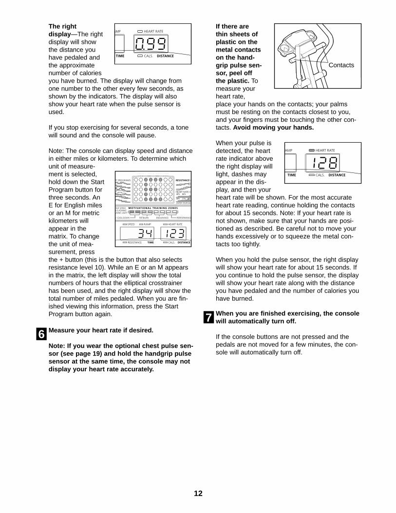
The rightdisplay —The rightdisplay will showthe distance youhave pedaled andthe approximatenumber of caloriesyou have burned. The display will change fromone number to the other every few seconds, asshown by the indicators. The display will alsoshow your heart rate when the pulse sensor isused.
If you stop exercising for several seconds, a tonewill sound and the console will pause.
Note: The console can display speed and distancein either miles or kilometers. To determine whichunit of measure-ment is selected,hold down the StartProgram button forthree seconds. AnE for English milesor an M for metrickilometers willappear in thematrix. To changethe unit of mea-surement, pressthe + button (this is the button that also selectsresistance level 10). While an E or an M appearsin the matrix, the left display will show the totalnumbers of hours that the elliptical crosstrainerhas been used, and the right display will show thetotal number of miles pedaled. When you are fin-ished viewing this information, press the StartProgram button again.
Measure your heart rate if desired.
Note: If you wear the optional chest pulse sen-sor (see page 19) and hold the handgrip pulsesensor at the same time, the console may notdisplay your heart rate accurately.
If there arethin sheets ofplastic on themetal contactson the hand-grip pulse sen-sor, peel offthe plastic. Tomeasure yourheart rate,place your hands on the contacts; your palmsmust be resting on the contacts closest to you,and your fingers must be touching the other con-tacts. Avoid moving your hands.
When your pulse isdetected, the heartrate indicator abovethe right display willlight, dashes mayappear in the dis-play, and then yourheart rate will be shown. For the most accurateheart rate reading, continue holding the contactsfor about 15 seconds. Note: If your heart rate isnot shown, make sure that your hands are posi-tioned as described. Be careful not to move yourhands excessively or to squeeze the metal con-tacts too tightly.
When you hold the pulse sensor, the right displaywill show your heart rate for about 15 seconds. Ifyou continue to hold the pulse sensor, the displaywill show your heart rate along with the distanceyou have pedaled and the number of calories youhave burned.
When you are finished exercising, the consolewill automatically turn off.
If the console buttons are not pressed and thepedals are not moved for a few minutes, the con-sole will automatically turn off.
76
Contacts

13
HOW TO USE A SMART PROGRAM
Make sure that the power cord is plugged in.
Refer to step 1 on page 11.
Press any button on the console or move thepedals to turn on the power.
Refer to step 2 on page 11.
Select one of the eight smart programs.
When the power isturned on, themanual mode willbe selected. Toselect a smart pro-gram, press theSelect Programbutton repeatedly until a P-1, P-2, P-3, P-4, P-5,P-6, P-7, or P-8 appears in the left display.
The profiles labeled P1 to P8 on the consoleshow the resistance and pace settings for thesmart programs. For example, profile P5 showsthat during program 5 both the resistance and thepace will gradually increase during the first half ofthe program, and then decrease during the lasthalf. Note: When you select a smart program, thematrix will show a simplified profile of the program.
Start the program.
To start the program, press the Start Programbutton or simply begin exercising. Each programis divided into several one-, two-, three-, and four-minute segments. One resistance setting and onepace setting are programmed for each segment.(The same resistance setting and/or pace settingmay be programmed for two or more consecutivesegments.)
The resistancesetting for the firstsegment will beshown in the flash-ing CurrentSegment columnof the matrix. Theresistance settingsfor the next five segments will be shown in thecolumns to the right. When only three secondsremain in the first segment, both the CurrentSegment column and the column to the right willflash, a series of tones will sound, and all resis-tance settings will move one column to the left.
The resistance setting for the second segmentwill then be shown in the flashing CurrentSegment column and the resistance of the ellipti-cal crosstrainer will automatically adjust to the sec-ond setting.
The pace settingsfor the program willbe shown by theTraining Zone bar.The lit indicators inthe bar will showyour actual pace. Ifan indicator to theright of the lit indi-cators flashes (seedrawing a),increase your pace.If an indicator to the left of any lit indicator flashes(see drawing b), decrease your pace. When noindicator is flashing, your pace matches the cur-rent pace setting. Important: The pace settingsare intended only to provide motivation. Youractual pace may be slower than the currentpace setting. Make sure to exercise at a pacethat is comfortable for you.
The program will continue until the resistance set-ting for the last segment is shown in the CurrentSegment column of the matrix and the left displayshows that no time remains in the program.
Note: During the program, you can adjust theangle of the incline ramp with the Ramp Angle but-tons. In addition, you can override the resistancesetting for the current segment, if desired, withthe Resistance buttons. However, when the nextsegment begins, the resistance will automaticallyadjust to the setting for the next segment. If youstop exercising for several seconds, a tone willsound and the program will pause. To restart theprogram, simply resume exercising.
Watch your progress with the two displays.
Refer to step 5 on page 11.
Measure your heart rate, if desired.
Refer to step 6 on page 12.
When the program is finished, the consolewill automatically turn off.
See step 7 on page 12.
7
6
5
4
3
2
1
Current Segment
a
b

14
HOW TO USE A HEART RATE PROGRAM
Each heart rate program helps you to keep your heartrate near a certain percentage of your maximum heartrate during your workout. (Your maximum heart rate isestimated by subtracting your age from 220. Forexample, if you are 30 years old, your maximum heartrate is 190.) Heart rate program 9 is designed to keepyour heart rate between 50% and 85% of your maxi-mum heart rate while you exercise; heart rate pro-gram 10 is designed to keep your heart rate between50% and 80% of your maximum heart rate.
Follow the steps below to use a heart rate program.
Make sure that the power cord is plugged in.
Refer to step 1 on page 11.
Press any button on the console or move thepedals to turn on the power.
Refer to step 2 on page 11.
Select one of the heart rate programs.
When the power isturned on, themanual mode willbe selected. Toselect a heart rateprogram, press theSelect Programbutton repeatedly until a P-9 or P-10 appears inthe left display.
The profiles labeled P9 and P10 on the consoleshow the resistance settings for the heart rateprograms. For example, profile P9 shows thatduring program 9 the resistance will graduallyincrease during the program and then decreasenear the end. Note: When you select a heart rateprogram, the matrix will show a simplified profileof the program.
Enter your age.
When a heart rateprogram is select-ed, the word AGEand the currentage setting willflash in the rightdisplay. You mustenter your age to use a heart rate program. Ifyou have already entered your age, press the
Enter Age button and go to step 5. If you havenot entered your age, press the + or – buttonrepeatedly (these are the buttons that selectresistance levels 9 and 10) to enter your age, andthen press the Enter Age button. Once you haveentered your age, your age will be saved inmemory.
Hold the handgrip pulse sensor.
To use a heart rate program, you must use thehandgrip pulse sensor (refer to step 6 on page12) or the optional chest pulse sensor (refer topage 19). If you use the handgrip pulse sensor, itis not necessary to hold the handgrips continu-ously during the program. However, you shouldhold the handgrips frequently for the program tooperate properly. Each time you hold the hand-grips, keep your hands on the metal contactsfor at least 30 seconds.
Start the program.
To start the program, press the Start Programbutton or simply begin exercising. Each heartrate program consists of twenty, one-minute seg-ments. One resistance setting and one heart ratesetting are programmed for each segment. (Thesame resistance setting and/or heart rate settingmay be programmed for two or more consecutivesegments.)
The resistance set-ting for the firstsegment will beshown in the flash-ing CurrentSegment column ofthe matrix. Theresistance settingsfor the next five segments will be shown in thecolumns to the right. When only three secondsremain in the first segment, both the CurrentSegment column and the column to the right willflash, a series of tones will sound, and all resis-tance settings will move one column to the left.The resistance setting for the second segmentwill then be shown in the flashing CurrentSegment column and the resistance of the ellipti-cal crosstrainer will automatically adjust to the sec-ond setting.
6
5
4
3
2
1
Current Segment

15
As you exercise, the Training Zone bar will helpyou to keep your heart rate near the heart ratesetting for the current segment. The lit indicatorsin the bar will showyour actual pace.When you hold thehandgrip pulsesensor (or wearthe optional chestpulse sensor), theconsole will period-ically compareyour heart rate tothe heart rate set-ting for the currentsegment; if neces-sary, an indicator in the bar will then flash toprompt you to increase or decrease your pace tobring your heart rate closer to the current heartrate setting. If an indicator to the right of the litindicators flashes (see drawing a above),increase your pace. If an indicator to the left ofany lit indicator flashes (see drawing b), decreaseyour pace. When no indicator is flashing, yourheart rate is near the current heart rate setting.Important: The heart rate settings are intend-ed only to provide motivation. Your actualheart rate may be slower than the currentheart rate setting. Make sure to exercise at apace that is comfortable for you.
The program will continue until the resistance set-ting for the last segment is shown in the CurrentSegment column of the matrix and the left displayshows that no time remains in the program.
Note: During the program, you can adjust the angleof the incline ramp with the Ramp Angle buttons. Inaddition, you can manually override the resistancesetting for the current segment, if desired, with theResistance buttons. However, when the next seg-ment begins, the resistance will automaticallyadjust to the setting for the next segment. If youstop exercising for six seconds or longer, a tonewill sound and the program will pause.
Watch your progress with the two displays.
Refer to step 5 on page 11.
When the program is finished, the console willautomatically turn off.
See step 7 on page 12.
HOW TO CONNECT YOUR CD PLAYER, VCR,OR COMPUTER
To use iFIT.com CDs , the elliptical crosstrainer mustbe connected to your portable CD player, portablestereo, home stereo, or computer with CD player. Seepages 15 to 17 for connecting instructions. To useiFIT.com videocassettes , the elliptical crosstrainermust be connected to your VCR. See page 17 for con-necting instructions. To use iFIT.com programsdirectly from our Web site , the elliptical crosstrainermust be connected to your home computer. See page17 for connecting instructions.
HOW TO CONNECT YOUR PORTABLE CD PLAYER
Note: If your CD player has separate LINE OUT andPHONES jacks, see instruction A below. If your CDplayer has only one jack, see instruction B.
A. Plug one end of the audio cable into the jackbeneath the console. Plug the other end of thecable into the LINE OUT jack on your CD player.Plug your headphones into the PHONES jack.
B. Plug one end of the audio cable into the jackbeneath the console. Plug the other end of thecable into a 1/8” Y-adapter (available at electronicsstores). Plug the Y-adapter into the PHONES jackon your CD player. Plug your headphones into theother side of the Y-adapter.
8
7
LINE OUT
PHONES LINE OUT
PHONES
AudioCable
Head-phones
A
PHONES
PHONES
AudioCable
1/8” Y-adapter
Headphones
B
a
b

16
HOW TO CONNECT YOUR PORTABLE STEREO
Note: If your stereo has an RCA-type AUDIO OUTjack, see instruction A below. If your stereo has a1/8” LINE OUT jack, see instruction B. If yourstereo has only a PHONES jack, see instruction C.
A. Plug one end of the audio cable into the jackbeneath the console. Plug the other end of thecable into the adapter. Plug the adapter into anAUDIO OUT jack on your stereo.
B. Plug one end of the audio cable into the jackbeneath the console. Plug the other end of thecable into the LINE OUT jack on your stereo. Donot use the adapter.
C. Plug one end of the audio cable into the jackbeneath the console. Plug the other end of thecable into a 1/8” Y-adapter (available at electronicsstores). Plug the Y-adapter into the PHONES jackon your stereo. Plug your headphones into theother side of the Y-adapter.
HOW TO CONNECT YOUR HOME STEREO
Note: If your stereo has an unused LINE OUT jack,see instruction A below. If the LINE OUT jack isbeing used, see instruction B.
A. Plug one end of the audio cable into the jackbeneath the console. Plug the other end of thecable into the adapter. Plug the adapter into theLINE OUT jack on your stereo.
B. Plug one end of the audio cable into the jackbeneath the console. Plug the other end of thecable into the adapter. Plug the adapter into anRCA Y-adapter (available at electronics stores).Next, remove the wire that is currently plugged intothe LINE OUT jack on your stereo and plug thewire into the unused side of the Y-adapter. Plug theY-adapter into the LINE OUT jack on your stereo.
AUDIO OUT
RIGHT
LEFT
PHONES
AudioCable
C
1/8” Y-adapter
Headphones
CD
VCR
AmpLINE OUT
LINE OUT
Audio CableAdapter
A
Audio Cable
Adapter
A, B
CD
VCR
AmpLINE OUT
AudioCable
RCAY-adapter
Wire removed fromLINE OUT jack
B
Adapter

17
HOW TO CONNECT YOUR COMPUTER
Note: If your computer has a 1/8” LINE OUT jack,see instruction A. If your computer has only aPHONES jack, see instruction B.
A. Plug one end of the audio cable into the jackbeneath the console. Plug the other end of thecable into the LINE OUT jack on your computer.
B. Plug one end of the audio cable into the jackbeneath the console. Plug the other end of thecable into a 1/8” Y-adapter (available at electronicsstores). Plug the Y-adapter into the PHONES jackon your computer. Plug your headphones or speak-ers into the other side of the Y-adapter.
HOW TO CONNECT YOUR VCR
Note: If your VCR has an unused AUDIO OUT jack,see instruction A below. If the AUDIO OUT jack isbeing used, see instruction B. If you have a TVwith a built-in VCR, see instruction B. If your VCRis connected to your home stereo, see HOW TOCONNECT YOUR HOME STEREO on page 16.
A. Plug one end of the audio cable into the jackbeneath the console. Plug the other end of thecable into the adapter. Plug the adapter into theAUDIO OUT jack on your VCR.
B. Plug one end of the audio cable into the jackbeneath the console. Plug the other end of thecable into the adapter. Plug the adapter into anRCA Y-adapter (available at electronics stores).Next, remove the wire that is currently plugged intothe AUDIO OUT jack on your VCR and plug thewire into the unused side of the Y-adapter. Plug theY-adapter into the AUDIO OUT jack on your VCR.
LINE OUT
AudioCable
A
PHONES
AudioCable
B
1/8” Y-adapter
Headphones/Speakers
AUDIO OUT
RIGHT
LEFT
VIDEO AUDIO
ANT. IN
RF OUTIN
OUT
CH3 4
Audio Cable
Adapter
A
VIDEO AUDIO
ANT. IN
RF OUTIN
OUT
CH3 4
Audio Cable Adapter
B
Wire removed fromAUDIO OUT jack
RCA Y-adapter

18
To use iFIT.com CDs or videocassettes, the ellipticalcrosstrainer must be connected to your portable CDplayer, portable stereo, home stereo, computer withCD player, or VCR. See HOW TO CONNECT YOURCD PLAYER, VCR, OR COMPUTER on page 15. Topurchase iFIT.com CDs and videocassettes, calltoll-free 1-800-735-0768.
Follow the steps below to use an iFIT.com CD orvideo program.
Make sure that the power cord is plugged in.
Refer to step 1 on page 11.
Press any button on the console or move thepedals to turn on the power.
Refer to step 2 on page 11.
Select the iFIT.com mode.
When the consoleis turned on, themanual mode willbe selected. Toselect the iFIT.commode, press theiFIT.com button.The indicator beside the button will light.
Insert the iFIT.com CD or videocassette.
If you are using an iFIT.com CD, insert the CDinto your CD player. If you are using an iFIT.comvideocassette, insert the videocassette into yourVCR.
Press the play button on your CD player orVCR.
A moment after the play button is pressed, yourpersonal trainer will begin guiding you throughyour workout. Simply follow your personal trainer’sinstructions.
The program will function in almost the same wayas a smart program (refer to step 4 on page 13).However, an electronic “chirping” sound will alertyou when the resistance and/or the pace setting isabout to change.
Note: If the resistance of the elliptical cross-trainer and/or the pace setting does notchange when a “chirp” is heard:
• Make sure that the indicator beside theiFIT.com button is lit.
• Adjust the volume of your CD player or VCR.If the volume is too high or too low, the con-sole may not detect the program signals.
• Make sure that the audio cable is properlyconnected and that it is fully plugged in.
Watch your progress with the two displays.
Refer to step 5 on page 11.
Measure your heart rate, if desired.
Refer to step 6 on page 12.
When the program is finished, the console willautomatically turn off.
See step 7 on page 12.
8
7
6
5
4
3
2
1
HOW TO USE IFIT.COM CD AND VIDEOPROGRAMS

19
HOW TO USE PROGRAMS DIRECTLY FROM OUR WEB SITE
Our Web site at www.iFIT.com allows you to playiFIT.com audio and video programs directly from theinternet. To use programs from our Web site, the ellip-tical crosstrainer must be connected to your homecomputer. See HOW TO CONNECT YOUR COMPUT-ER on page 17. In addition, you must have an internetconnection and an internet service provider. A list ofspecific system requirements will be found on our Website.
Follow the steps below to use a program from our Web site.
Make sure that the power cord is plugged in.
Refer to step 1 on page 11.
Press any button on the console or move thepedals to turn on the power.
Refer to step 2 on page 11.
Select the iFIT.com mode.
When the consoleis turned on, themanual mode willbe selected. Toselect the iFIT.commode, press theiFIT.com button.The indicator beside the button will light.
Go to your computer and start an internetconnection.
Start your Web browser, if necessary, and goto our Web site at www.iFIT.com.
Follow the desired links on our Web site toselect a program.
Read and follow the on-line instructions for usinga program.
Follow the on-line instructions to start theprogram.
When you start the program, an on-screen count-down will begin.
Return to the elliptical crosstrainer and beginexercising.
When the on-screen countdown ends, the pro-gram will begin. The program will function inalmost the same way as a Smart program (refer tostep 4 on page 13). However, an electronic “chirp-ing” sound will alert you when the resistanceand/or the pace setting is about to change.
Follow your progress with the two displays.
Refer to step 5 on page 11.
Measure your heart rate if desired.
Refer to step 6 on page 12.
When you are finished exercising, the consolewill automatically turn off.
Refer to step 7 on page 12.
THE OPTIONAL CHEST PULSE SENSOR
The optional chest pulse sensor provides hands-freeoperation and continuously monitors your heart rateduring your workouts. To purchase the optionalchest pulse sensor, call toll-free 1-800-734-2377.
11
10
9
8
7
6
5
4
3
2
1

20
Inspect and properly tighten all parts of the ellipticalcrosstrainer regularly. Replace any worn parts immedi-ately.
For smoothoperation of theellipticalcrosstrainer, theincline rampshould be keptclean. Using asoft cloth andmild detergent,clean dust andother residuefrom the inclineramp where the wheels make contact with it. Otherparts of the elliptical crosstrainer can also be cleanedin this way. Keep liquids off the console. Never useabrasives or solvents.
HOW TO ADJUST THE REED SWITCH
If the console does not display correct feedback, thereed switch should be adjusted. To adjust the reedswitch, the Side Shields (47, 48) and the Pedal Disks(40) must be removed. Remove the indicated Screws(72, 88) from both Side Shields and Pedal Disks. Pullthe Pedal Disks out of the Side Shields. Lift the SideShields off the elliptical crosstrainer.
Next, locate the Reed Switch (50). Turn the Flywheel(37) until the Magnet (55) is aligned with the ReedSwitch. Loosen, but do not remove, the indicatedScrew (72). Slide the Reed Switch slightly closer to oraway from the Magnet. Retighten the Screw. Rock theFlywheel forward and back just enough that theMagnet passes the Reed Switch repeatedly. Repeatuntil the console displays correct feedback. When theReed Switch is correctly adjusted, reattach the sideshields and the pedal disks.
HOW TO LEVEL THE ELLIPTICAL CROSSTRAINER
If the ellipticalcrosstrainerrocks slightlyduring use,turn one orboth of theleveling feetunder the rearstabilizer untilthe rockingmotion is elim-inated.
MAINTENANCE AND TROUBLESHOOTING
InclineRamp
Wheel
LevelingFeet
88
47
48
40
72
72
3750
55

21
CONDITIONING GUIDELINES
The following guidelines will help you to plan yourexercise program. Remember that proper nutritionand adequate rest are essential for successful results.
EXERCISE INTENSITY
Whether your goal is to burn fat or to strengthen yourcardiovascular system, the key to achieving thedesired results is to exercise with the proper intensity.The proper intensity level can be found by using yourheart rate as a guide. The chart below shows recom-mended heart rates for fat burning, maximum fatburning, and cardiovascular (aerobic) exercise.
To find the proper heart rate for you, first find your ageon the bottom line of the chart (ages are rounded offto the nearest ten years). Next, find the three numbersabove your age. The three numbers are your “trainingzone.” The lower two numbers are recommendedheart rates for fat burning; the highest number is therecommended heart rate for aerobic exercise.
Fat Burning
To burn fat effectively, you must exercise at a relative-ly low intensity level for a sustained period of time.
During the first few minutes of exercise, your bodyuses easily accessible carbohydrate calories for ener-gy. Only after the first few minutes of exercise doesyour body begin to use stored fat calories for energy.If your goal is to burn fat, adjust the intensity of yourexercise until your heart rate is near the lowest num-ber in your training zone as you exercise.
For maximum fat burning, adjust the intensity of yourexercise until your heart rate is near the middle num-ber in your training zone as you exercise.
Aerobic Exercise
If your goal is to strengthen your cardiovascular sys-tem, your exercise must be “aerobic.” Aerobic exer-cise is activity that requires large amounts of oxygenfor prolonged periods of time. This increases thedemand on the heart to pump blood to the muscles,and on the lungs to oxygenate the blood. For aerobicexercise, adjust the intensity of your exercise untilyour heart rate is near the highest number in yourtraining zone as you exercise.
WORKOUT GUIDELINES
Each workout should include the following three parts:
A warm-up , consisting of 5 to 10 minutes of stretchingand light exercise. A proper warm-up increases yourbody temperature, heart rate, and circulation in prepa-ration for exercise.
Training zone exercise , consisting of 20 to 30 min-utes of exercising with your heart rate in your trainingzone. (During the first few weeks of your exercise program, do not keep your heart rate in your trainingzone for longer than 20 minutes.)
A cool-down , with 5 to 10 minutes of stretching. Thiswill increase the flexibility of your muscles and willhelp to prevent post-exercise problems.
EXERCISE FREQUENCY
To maintain or improve your condition, complete threeworkouts each week, with at least one day of restbetween workouts. After a few months of regular exer-cise, you may complete up to five workouts each weekif desired. The key to success is to make exercise aregular and enjoyable part of your everyday life.
WARNING:• Before beginning this or any exercise pro-
gram, consult your physician. This is espe-cially important for persons over the age of35 or persons with pre-existing health prob-lems.
• The pulse sensor is not a medical device.Various factors may affect the accuracy ofheart rate readings. The pulse sensor isintended only as an exercise aid in deter-mining heart rate trends in general.

22
Note: # indicates a non-illustrated part. Specifications are subject to change without notice. See the back coverof this manual for information about ordering replacement parts.
1 1 Frame2 1 Upright3 1 Left Spring Arm4 1 Right Spring Arm5 1 Incline Ramp6 2 Crank Arm7 1 Left Upper Body Arm8 1 Large Pulley9 2 Frame Bearing
10 1 Plastic Crank Spacer11 1 Flat Delrin Washer12 1 Idler Bracket13 1 Power Cord14 2 Leveling Foot15 4 Push Nut16 1 M10 x 25mm Flat Head Bolt17 2 M8.5 Flat Washer18 2 Foam Grip19 1 Arm Axle20 2 Plastic Arm Sleeve21 2 Chrome Tube22 11 M10 Split Washer23 6 Arm Bushing24 2 56mm Spacer25 2 Frame Endcap26 2 M10 Nylon Locknut27 2 M10 Union Bolt Set28 1 Belt29 2 Incline Axle30 4 M8 x 19mm Screw31 10 Incline Bushing32 4 Incline Ramp Cap33 4 M8 Washer34 2 Pivot Axle Cap35 4 Console Screw36 1 Spring37 1 Flywheel38 2 Flywheel Bearing39 1 Flywheel Axle40 2 Pedal Disk41 1 Left Pedal 42 1 Right Pedal 43 12 M6 x 33mm Flat Head Screw44 2 Incline Wheel45 2 Stabilizer Wheel46 2 M8 Union Bolt Set47 1 Left Side Shield48 1 Right Side Shield49 2 M5 x 6mm Screw50 1 Reed Switch/Wire51 1 Extension Wire Harness52 1 Reed Switch Bracket53 2 Spring Bracket54 1 Reed Switch Clamp55 1 Magnet56 1 Left Rear Spring Bracket
57 1 Right Rear Spring Bracket58 4 M8 Split Washer59 1 Rear Stabilizer60 4 M10 x 56mm Screw61 2 M10 x 33mm Carriage Bolt62 2 Front Stabilizer Endcap63 2 M10 Washer64 2 Rear Stabilizer Endcap65 4 M10 x 43mm Screw66 1 “J” Bolt67 4 Spring Bracket Bushing68 1 Eyebolt69 1 “C” Magnet70 1 Adjustment Bracket71 3 M4 x 63.5mm Screw72 8 M4 x 16mm Screw73 10 M5 x 16mm Screw74 2 Axle Cover75 1 Right Upper Body Arm76 4 Pedal Bushing77 2 Adjustment Knob78 2 Snap Ring79 2 Spring Spacer80 4 M8 Nylon Locknut81 1 Adjustment Cable Assembly82 1 Resistance Motor83 2 Flange Screw84 1 M6 x 38mm Bolt85 1 Wire Harness86 12 M6 Nylon Locknut87 1 Console 88 4 M5 x 25mm Screw89 3 Stop Nut90 1 Front Stabilizer91 1 Side Shield Support92 12 M6 Washer93 4 Console Washer94 1 Incline Motor95 1 Reed Switch Lock96 1 Incline Reed Switch97 4 Tree Fastener98 1 Left Incline Shield99 1 Right Incline Shield
100 1 Incline Bolt101 2 Incline Spacer102 3 M10 x 25mm Screw103 1 Zip Tie104 3 #8 x 3/8” Screw105 1 Wiring Board106 1 Junction Box/Cover107 1 Grommet
# 1 Grease# 1 Teflon® Lubricant# 1 Push Nut Tool# 2 Allen Wrench# 1 User’s Manual
Key No. Qty. Description Key No. Qty. Description
PART LIST—Model No. NTE99021 R1202A
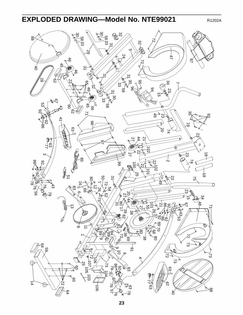
EXPLODED DRAWING—Model No. NTE99021 R1202A
23
85
13
88
40
76
25
76
3
51 75
18
87
40
41
1
683
109
9
898489
64
64 59
86
83
1116
80
261266
5254
5072
72
4772
23
2315
34
36 69
8970
8068
1738
80
8017 39 38
55
37
91
73
3131
8281
7
49
20
21
74
23
23
7419
49
2315
23
3448
8871
73
73
72
722
20
44
35 93
25
6060
43
43
2727
53
56
63
61
77
78
79
92
8692
8692
92
22
67
73
14
73
21
46
45
6290
62
46
45 4665
46
22
28
5
30
5831
31
32
3129
5830
33
33
32
32
5830
33 31
30
5831
33 96
95
94
98
99
4261
6377
78
7676
435779
86 92
4
9286
4353
9286
67
92
27
4427
18
103107
72 106
104
105
106
73
100
101
26101
97
71
24
102
1022222
22

Part No. 189553 R1202A Printed in China © 2002 ICON Health & Fitness, Inc.
HOW TO ORDER REPLACEMENT PARTSTo order replacement parts, simply call our Customer Service Department toll-free at 1-888-825-2588, Mondaythrough Friday, 6 a.m. until 6 p.m. Mountain Time (excluding holidays). To help us assist you, please be prepared to give the following information when calling:
• The MODEL NUMBER of the product (NTE99021)
• The NAME of the product (NordicTrack® CXT 980 elliptical crosstrainer)
• The SERIAL NUMBER of the product (see the front cover of this manual)
• The KEY NUMBER and DESCRIPTION of the part(s) from page 22 of this manual
LIMITED WARRANTY
WHAT IS COVERED—The entire NordicTrack® elliptical crosstrainer (“Product”) is warranted to be free of all defects in material andworkmanship.
WHO IS COVERED—The original purchaser or any person receiving the Product as a gift from the original purchaser.
HOW LONG IS IT COVERED—ICON Health & Fitness, Inc. (“ICON”), warrants the product for one year after the date of purchase.Labor is covered for one year.
WHAT WE DO TO CORRECT COVERED DEFECTS—We will ship to you, without charge, any replacement part or component, pro-viding the repairs are authorized by ICON first and are performed by an ICON trained and authorized service provider, or, at ouroption, we will replace the Product.
WHAT IS NOT COVERED—Any failures or damage caused by unauthorized service, misuse, accident, negligence, improper assem-bly or installation, alterations, modifications without our written authorization or by failure on your part to use, operate, and maintainas set out in your User’s Manual (“Manual”).
WHAT YOU MUST DO—Always retain proof of purchase, such as your bill of sale; store, operate, and maintain the Product as spec-ified in the Manual; notify our Customer Service Department of any defect within 10 days after discovery of the defect; as instruct-ed, return any defected part for replacement or, if necessary, the entire product, for repair.
USER’S MANUAL—It is VERY IMPORTANT THAT YOU READ THE MANUAL before operating the Product. Remember to do theperiodic maintenance requirements specified in the Manual to assure proper operation and your continued satisfaction.
HOW TO GET PARTS AND SERVICE—Simply call our Customer Service Department at 1-888-825-2588 and tell them your nameand address and the serial number of your Product. They will tell you how to get a part replaced, or if necessary, arrange for servicewhere your Product is located or advise you how to ship the Product for service. Before shipping, always obtain a ReturnAuthorization Number (RA No.) from our Customer Service Department; securely pack your Product (save the original shipping car-ton if possible); put the RA No. on the outside of the carton and insure the product. Include a letter explaining the product or prob-lem and a copy of your proof of purchase if you believe the service is covered by warranty.
ICON is not responsible or liable for indirect, special or consequential damages arising out of or in connection with the use or per-formance of the product or damages with respect to any economic loss, loss of property, loss of revenues or profits, loss of enjoy-ment or use, costs of removal, installation or other consequential damages of whatsoever nature. Some states do not allow the exclu-sion or limitation of incidental or consequential damages. Accordingly, the above limitation may not apply to you.
The warranty extended hereunder is in lieu of any and all other warranties and any implied warranties of merchantability or fitnessfor a particular purpose is limited in its scope and duration to the terms set forth herein. Some states do not allow limitations on howlong an implied warranty lasts. Accordingly, the above limitation may not apply to you.
No one is authorized to change, modify or extend the terms of this limited warranty. This warranty gives you specific legal rights andyou may have other rights which vary from state to state.
ICON HEALTH & FITNESS, INC., 1500 S. 1000 W., LOGAN, UT 84321-9813