user's guide cts6000 webcontrol - nilan user's guide cts6000 webcontrol valid for: ......
TRANSCRIPT
User's Guide
CTS6000 WebControl
Valid for: CTS6000, SW1.0094 Version 1.08, 01-05-2016
Contents
Contents ......................................................................................................................................... 2 List of figures .................................................................................................................................. 3 Introduction ..................................................................................................................................... 4
Introduction to CTS6000 ............................................................................................................. 4 Reading instructions ................................................................................................................... 4
Quick startup .................................................................................................................................. 5 Daily operation ............................................................................................................................... 6
Weekly program and yearly program .......................................................................................... 6 Room temperature ...................................................................................................................... 7 Alarm management ..................................................................................................................... 7 Historical graphs ......................................................................................................................... 8 Trend graphs .............................................................................................................................. 9 About the program ...................................................................................................................... 9 Restarting the system ................................................................................................................. 9 Logging out ................................................................................................................................. 9
CTS6000 WebControl settings ..................................................................................................... 10 System information ................................................................................................................... 10 Password .................................................................................................................................. 10 Rights ....................................................................................................................................... 10 Tabs .......................................................................................................................................... 10 Backing up system settings ....................................................................................................... 11 Restoring factory settings .......................................................................................................... 11 Updating software ..................................................................................................................... 11
System configuration .................................................................................................................... 13 PI diagram ................................................................................................................................ 13 System configuration................................................................................................................. 14 General regulation parameters .................................................................................................. 14 Regulation ................................................................................................................................. 14 Filter monitor ............................................................................................................................. 15 Component priority .................................................................................................................... 15 Fan settings .............................................................................................................................. 15 Pressure limits .......................................................................................................................... 15 Sensor offsets ........................................................................................................................... 15 VLT settings .............................................................................................................................. 15 VLT parameters ........................................................................................................................ 16 NETR unit settings .................................................................................................................... 16 Programming ............................................................................................................................ 16 Universal ports .......................................................................................................................... 16 Pre-cooling coil ......................................................................................................................... 16
Network settings ........................................................................................................................... 17 Network configuration ............................................................................................................... 17 RS232 configuration ................................................................................................................. 17 RS485 configuration ................................................................................................................. 18 Email alarm settings .................................................................................................................. 18
Appendices ................................................................................................................................... 19 Description of alarms ................................................................................................................ 19 Username and password for CTS6000 ..................................................................................... 21 Description of sensors and components.................................................................................... 22 Network settings on PC with Windows ...................................................................................... 23 Creating a separate xDSL connection ....................................................................................... 24
List of figures
Figure 1 Example of menu options ................................................................................................. 4 Figure 2 CTS6000 PCB with network port ...................................................................................... 5 Figure 3 Log-in window................................................................................................................... 5 Figure 4 Week program .................................................................................................................. 6 Figure 5 Year program.................................................................................................................... 6 Figure 6 Room temperature ............................................................................................................ 7 Figure 7 Event log .......................................................................................................................... 7 Figure 8 Historical graph ................................................................................................................. 8 Figure 9 Trend graph ...................................................................................................................... 9 Figure 10 Permissions .................................................................................................................. 10 Figure 11 Tabs ............................................................................................................................. 10 Figure 12 System settings ............................................................................................................ 11 Figure 13 Reset to factory defaults ............................................................................................... 11 Figure 14 Firmware update ........................................................................................................... 12 Figure 15 PI diagram .................................................................................................................... 13 Figure 16 System configuration .................................................................................................... 14 Figure 17 Regulation .................................................................................................................... 14 Figure 18 Fan configuration .......................................................................................................... 15 Figure 19 Programming ................................................................................................................ 16 Figure 20 Network configuration ................................................................................................... 17 Figure 21 RS485 configuration ..................................................................................................... 18 Figure 22 E-mail alarm settings .................................................................................................... 18 Figure 23 Network Connections .................................................................................................... 23 Figure 24 LAN Connection Properties .......................................................................................... 23 Figure 25 Internet Protocol (TCP/IP) Properties ........................................................................... 24
User's Guide for CTS6000 WebControl Version 1.07
Subject to alteration without notice. NILAN A/S Page 4 of 24
Introduction
Please check that the following documents have been supplied with the unit: Installation instructions User's Guide for CTS6000 WebControl (this document) Wiring diagram Warranty certificate
The purpose of this guide is to provide a clear, detailed description of the possibilities offered by CTS6000 WebControl. The guide may contain functions and facilities which are not available on your system. For technical information on the possibilities provided by CTS6000 WebControl, please refer to "Function Description for CTS6000 WebControl".
Introduction to CTS6000
CTS6000 is a control unit for commercial ventilation systems supplied by Nilan A/S. CTS6000 was developed in Denmark and is also produced there. CTS6000 is designed to meet future requirements on improving the possibility of optimizing ventilation systems and reducing running costs. As the name suggests, CTS6000 WebControl is an Internet-based monitoring program. The program is pre-installed in the unit and there is thus no need for software other than an Internet browser capable of running Java applications. If the unit is connected to the Internet, it is possible to log into the system from a PC anywhere in the world.
Reading instructions
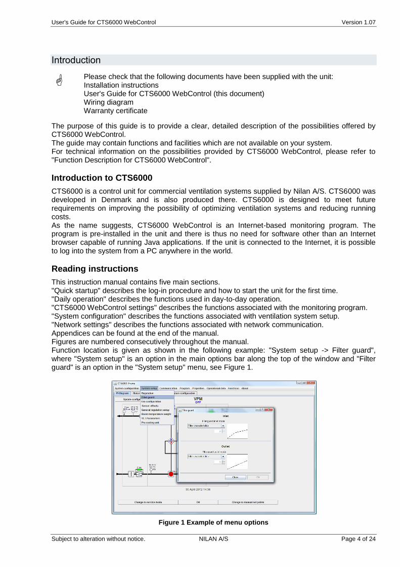
This instruction manual contains five main sections. "Quick startup" describes the log-in procedure and how to start the unit for the first time. "Daily operation" describes the functions used in day-to-day operation. "CTS6000 WebControl settings" describes the functions associated with the monitoring program. "System configuration" describes the functions associated with ventilation system setup. "Network settings" describes the functions associated with network communication. Appendices can be found at the end of the manual. Figures are numbered consecutively throughout the manual. Function location is given as shown in the following example: "System setup -> Filter guard", where "System setup" is an option in the main options bar along the top of the window and "Filter guard" is an option in the "System setup" menu, see Figure 1.
Figure 1 Example of menu options
User's Guide for CTS6000 WebControl Version 1.07
Subject to alteration without notice. NILAN A/S Page 5 of 24
Quick startup
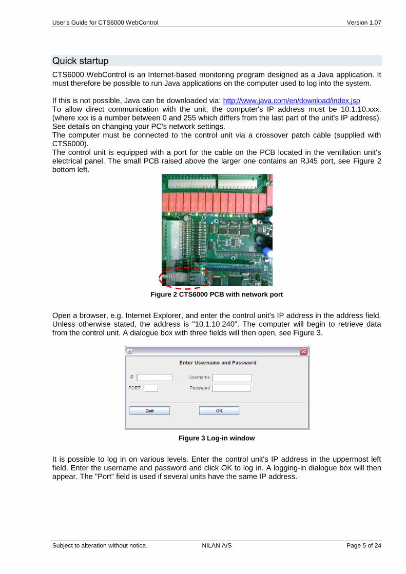
CTS6000 WebControl is an Internet-based monitoring program designed as a Java application. It must therefore be possible to run Java applications on the computer used to log into the system. If this is not possible, Java can be downloaded via: http://www.java.com/en/download/index.jsp To allow direct communication with the unit, the computer's IP address must be 10.1.10.xxx. (where xxx is a number between 0 and 255 which differs from the last part of the unit's IP address). See details on changing your PC's network settings. The computer must be connected to the control unit via a crossover patch cable (supplied with CTS6000). The control unit is equipped with a port for the cable on the PCB located in the ventilation unit's electrical panel. The small PCB raised above the larger one contains an RJ45 port, see Figure 2 bottom left.
Figure 2 CTS6000 PCB with network port
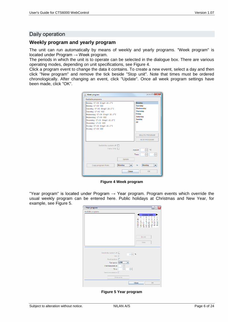
Open a browser, e.g. Internet Explorer, and enter the control unit's IP address in the address field. Unless otherwise stated, the address is "10.1.10.240". The computer will begin to retrieve data from the control unit. A dialogue box with three fields will then open, see Figure 3.
Figure 3 Log-in window
It is possible to log in on various levels. Enter the control unit's IP address in the uppermost left field. Enter the username and password and click OK to log in. A logging-in dialogue box will then appear. The "Port" field is used if several units have the same IP address.
User's Guide for CTS6000 WebControl Version 1.07
Subject to alteration without notice. NILAN A/S Page 6 of 24
Daily operation
Weekly program and yearly program
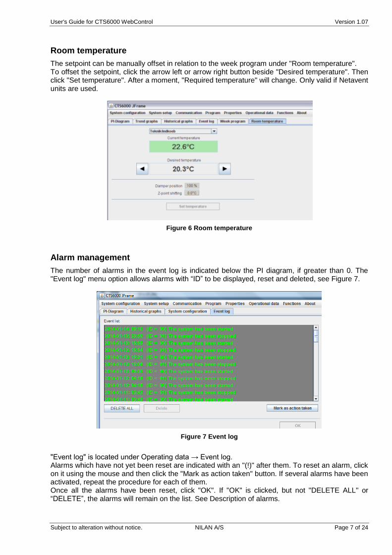
The unit can run automatically by means of weekly and yearly programs. "Week program" is located under Program → Week program. The periods in which the unit is to operate can be selected in the dialogue box. There are various operating modes, depending on unit specifications, see Figure 4. Click a program event to change the data it contains. To create a new event, select a day and then click "New program" and remove the tick beside "Stop unit". Note that times must be ordered chronologically. After changing an event, click "Update". Once all week program settings have been made, click "OK".
Figure 4 Week program
"Year program" is located under Program → Year program. Program events which override the usual weekly program can be entered here. Public holidays at Christmas and New Year, for example, see Figure 5.
Figure 5 Year program
User's Guide for CTS6000 WebControl Version 1.07
Subject to alteration without notice. NILAN A/S Page 7 of 24
Room temperature
The setpoint can be manually offset in relation to the week program under "Room temperature". To offset the setpoint, click the arrow left or arrow right button beside "Desired temperature". Then click "Set temperature". After a moment, "Required temperature" will change. Only valid if Netavent units are used.
Figure 6 Room temperature
Alarm management
The number of alarms in the event log is indicated below the PI diagram, if greater than 0. The "Event log" menu option allows alarms with “ID” to be displayed, reset and deleted, see Figure 7.
Figure 7 Event log
"Event log" is located under Operating data → Event log. Alarms which have not yet been reset are indicated with an "(!)" after them. To reset an alarm, click on it using the mouse and then click the "Mark as action taken" button. If several alarms have been activated, repeat the procedure for each of them. Once all the alarms have been reset, click "OK". If "OK" is clicked, but not "DELETE ALL" or “DELETE”, the alarms will remain on the list. See Description of alarms.
User's Guide for CTS6000 WebControl Version 1.07
Subject to alteration without notice. NILAN A/S Page 8 of 24
Historical graphs
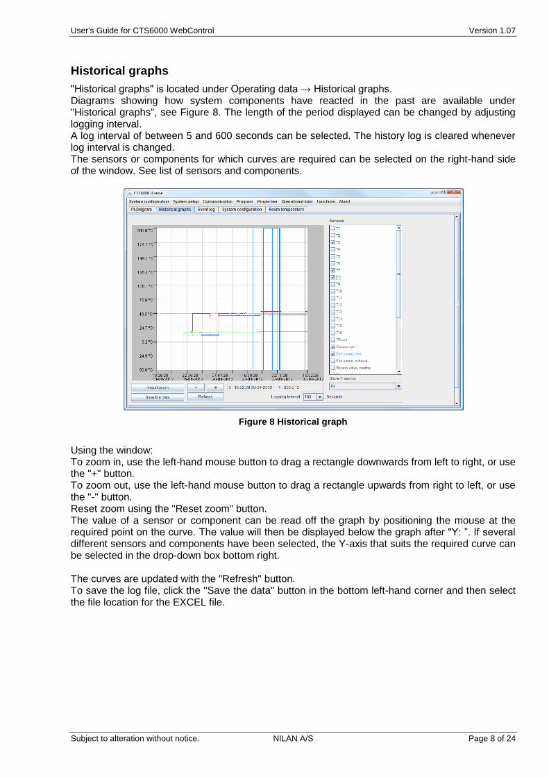
"Historical graphs" is located under Operating data → Historical graphs. Diagrams showing how system components have reacted in the past are available under "Historical graphs", see Figure 8. The length of the period displayed can be changed by adjusting logging interval. A log interval of between 5 and 600 seconds can be selected. The history log is cleared whenever log interval is changed. The sensors or components for which curves are required can be selected on the right-hand side of the window. See list of sensors and components.
Figure 8 Historical graph
Using the window: To zoom in, use the left-hand mouse button to drag a rectangle downwards from left to right, or use the "+" button. To zoom out, use the left-hand mouse button to drag a rectangle upwards from right to left, or use the "-" button. Reset zoom using the "Reset zoom" button. The value of a sensor or component can be read off the graph by positioning the mouse at the required point on the curve. The value will then be displayed below the graph after "Y: ”. If several different sensors and components have been selected, the Y-axis that suits the required curve can be selected in the drop-down box bottom right. The curves are updated with the "Refresh" button. To save the log file, click the "Save the data" button in the bottom left-hand corner and then select the file location for the EXCEL file.
User's Guide for CTS6000 WebControl Version 1.07
Subject to alteration without notice. NILAN A/S Page 9 of 24
Trend graphs
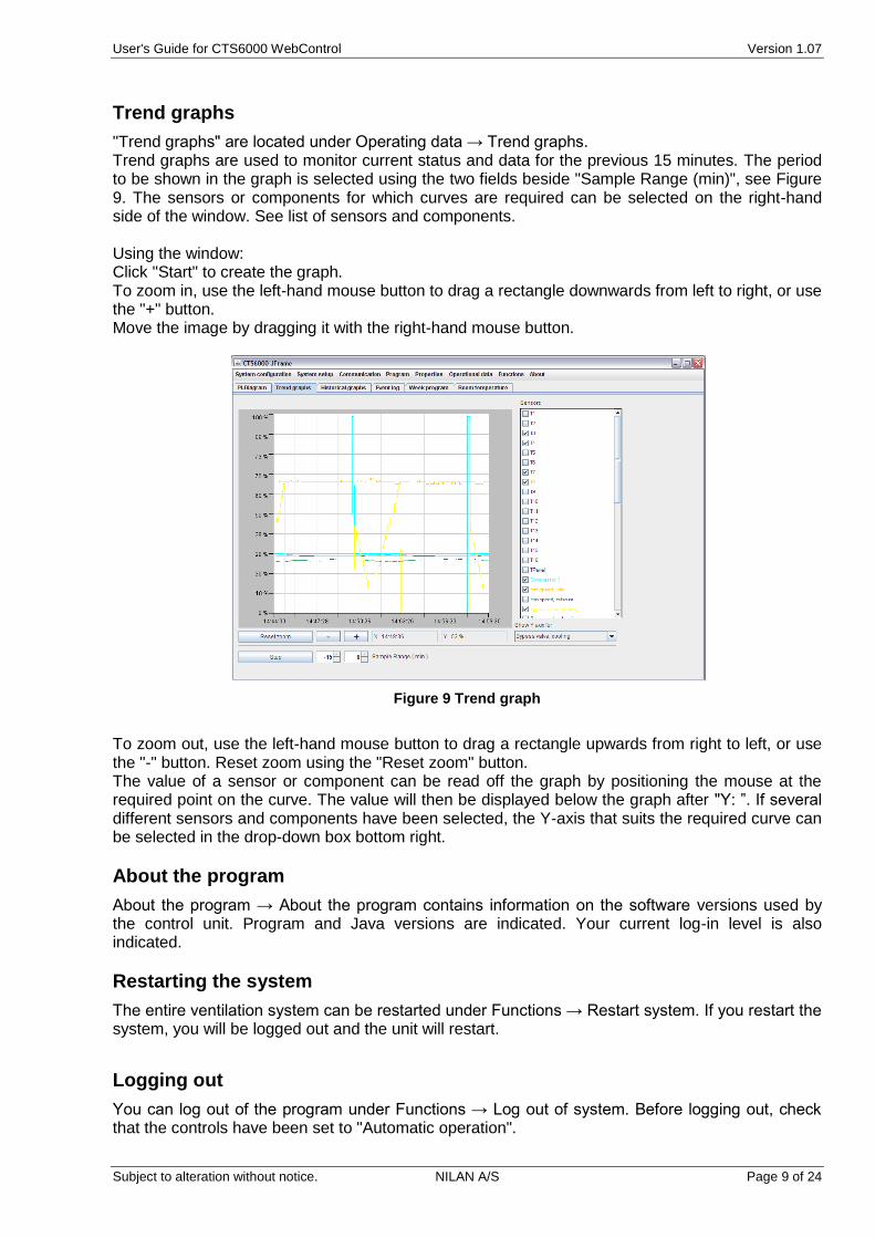
"Trend graphs" are located under Operating data → Trend graphs. Trend graphs are used to monitor current status and data for the previous 15 minutes. The period to be shown in the graph is selected using the two fields beside "Sample Range (min)", see Figure 9. The sensors or components for which curves are required can be selected on the right-hand side of the window. See list of sensors and components. Using the window: Click "Start" to create the graph. To zoom in, use the left-hand mouse button to drag a rectangle downwards from left to right, or use the "+" button. Move the image by dragging it with the right-hand mouse button.
Figure 9 Trend graph
To zoom out, use the left-hand mouse button to drag a rectangle upwards from right to left, or use the "-" button. Reset zoom using the "Reset zoom" button. The value of a sensor or component can be read off the graph by positioning the mouse at the required point on the curve. The value will then be displayed below the graph after "Y: ”. If several different sensors and components have been selected, the Y-axis that suits the required curve can be selected in the drop-down box bottom right.
About the program
About the program → About the program contains information on the software versions used by the control unit. Program and Java versions are indicated. Your current log-in level is also indicated.
Restarting the system
The entire ventilation system can be restarted under Functions → Restart system. If you restart the system, you will be logged out and the unit will restart.
Logging out
You can log out of the program under Functions → Log out of system. Before logging out, check that the controls have been set to "Automatic operation".
User's Guide for CTS6000 WebControl Version 1.07
Subject to alteration without notice. NILAN A/S Page 10 of 24
CTS6000 WebControl settings
System information
"System information" is located under System configuration → System information. The name of the ventilation unit can be entered here.
Password
You can change your log-in password under Functions → Password. See Log-in information.
Rights
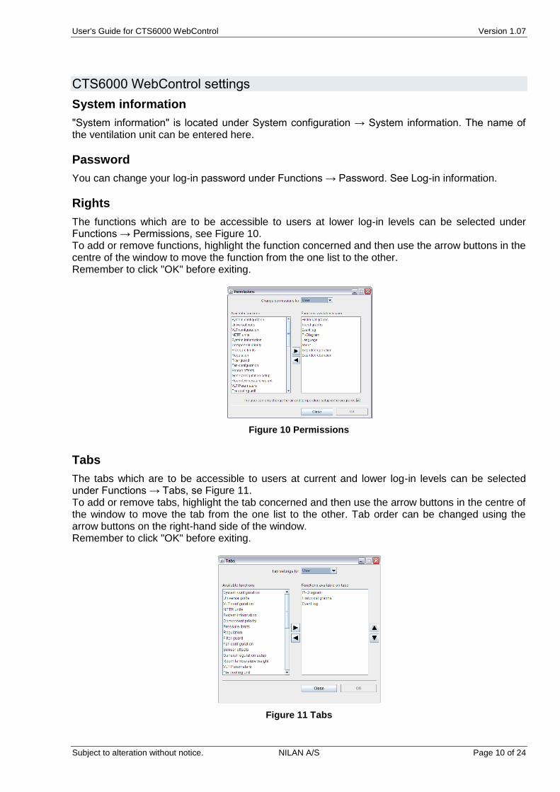
The functions which are to be accessible to users at lower log-in levels can be selected under Functions → Permissions, see Figure 10. To add or remove functions, highlight the function concerned and then use the arrow buttons in the centre of the window to move the function from the one list to the other. Remember to click "OK" before exiting.
Figure 10 Permissions
Tabs
The tabs which are to be accessible to users at current and lower log-in levels can be selected under Functions → Tabs, se Figure 11. To add or remove tabs, highlight the tab concerned and then use the arrow buttons in the centre of the window to move the tab from the one list to the other. Tab order can be changed using the arrow buttons on the right-hand side of the window. Remember to click "OK" before exiting.
Figure 11 Tabs
User's Guide for CTS6000 WebControl Version 1.07
Subject to alteration without notice. NILAN A/S Page 11 of 24
Backing up system settings
After making changes to the Week program or other settings, it is advisable to take a backup of the new settings. This can be done by selecting Functions → Backup and restore, see Figure 12. To save the current settings, click "Save system configuration". A new dialogue box will then appear, allowing you to specify a file name and location. To retrieve previously saved settings, click "Load system configuration" and select the required file. The system settings selected will then be restored. After retrieving stored settings, close the browser window completely before logging in again.
Figure 12 System settings
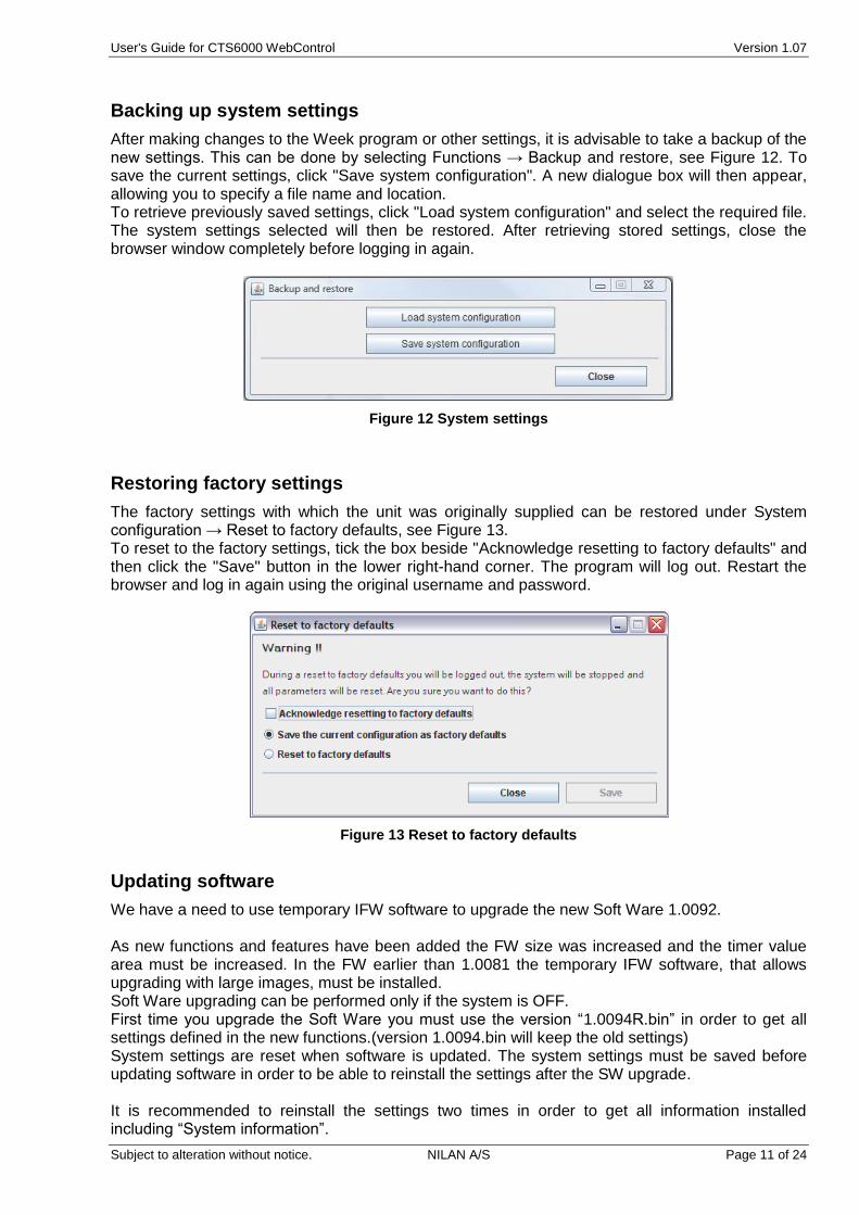
Restoring factory settings
The factory settings with which the unit was originally supplied can be restored under System configuration → Reset to factory defaults, see Figure 13. To reset to the factory settings, tick the box beside "Acknowledge resetting to factory defaults" and then click the "Save" button in the lower right-hand corner. The program will log out. Restart the browser and log in again using the original username and password.
Figure 13 Reset to factory defaults
Updating software
We have a need to use temporary IFW software to upgrade the new Soft Ware 1.0092. As new functions and features have been added the FW size was increased and the timer value area must be increased. In the FW earlier than 1.0081 the temporary IFW software, that allows upgrading with large images, must be installed. Soft Ware upgrading can be performed only if the system is OFF. First time you upgrade the Soft Ware you must use the version “1.0094R.bin” in order to get all settings defined in the new functions.(version 1.0094.bin will keep the old settings) System settings are reset when software is updated. The system settings must be saved before updating software in order to be able to reinstall the settings after the SW upgrade. It is recommended to reinstall the settings two times in order to get all information installed including “System information”.
User's Guide for CTS6000 WebControl Version 1.07
Subject to alteration without notice. NILAN A/S Page 12 of 24
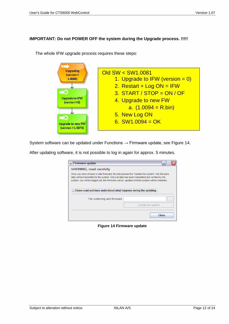
IMPORTANT: Do not POWER OFF the system during the Upgrade process. !!!!! The whole IFW upgrade process requires these steps:
System software can be updated under Functions → Firmware update, see Figure 14. After updating software, it is not possible to log in again for approx. 5 minutes.
Figure 14 Firmware update
Old SW < SW1.0081 1. Upgrade to IFW (version = 0)
2. Restart + Log ON = IFW
3. START / STOP = ON / OF
4. Upgrade to new FW
a. (1.0094 = R.bin)
5. New Log ON
6. SW1.0094 = OK
User's Guide for CTS6000 WebControl Version 1.07
Subject to alteration without notice. NILAN A/S Page 13 of 24
System configuration
The functions described in this section concern system components. Changes should therefore be made with care. If changes are to be made in any of the functions described, the system must first be stopped. The operator should also have direct physical access to the unit. This manual simply introduces the functions. For more detailed information, see "Installer’s Guide CTS6000 WebControl".
PI diagram
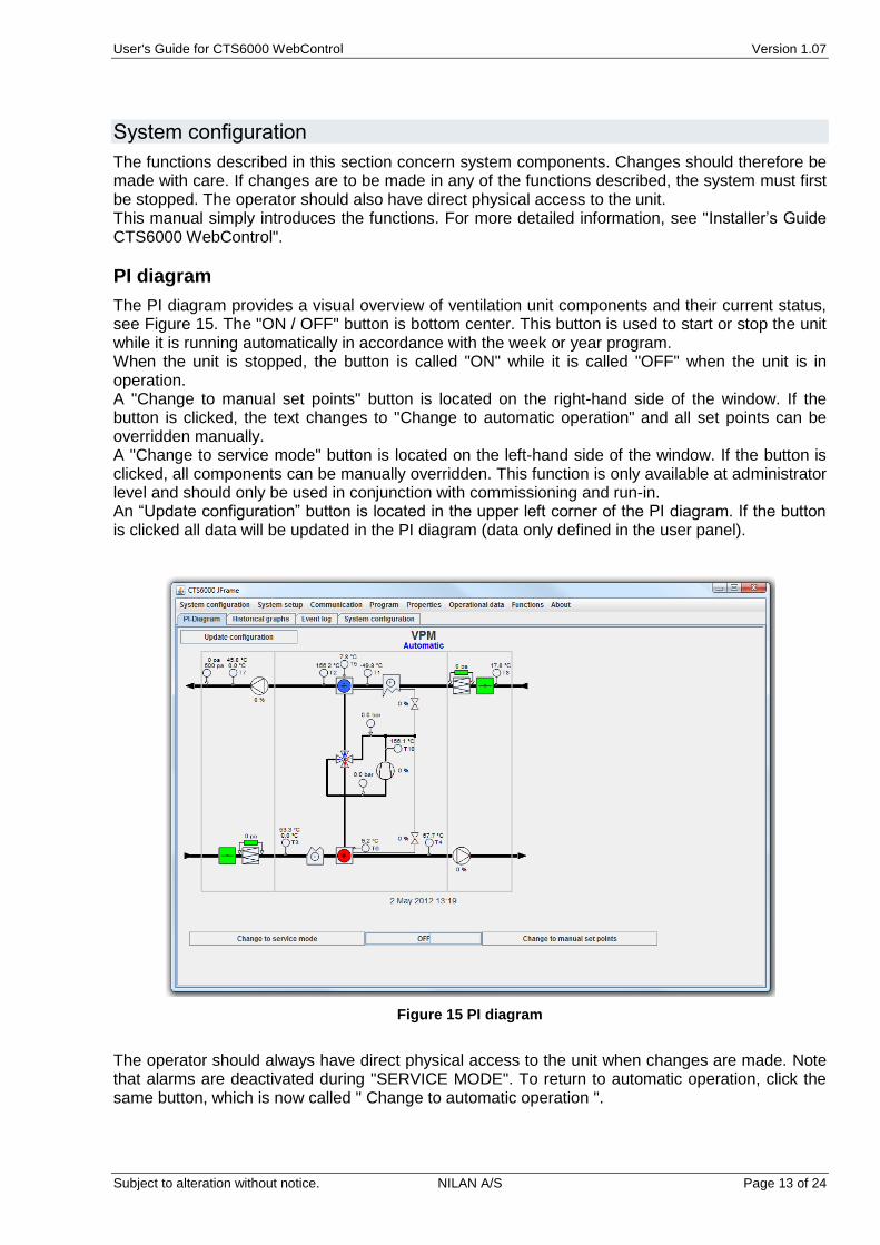
The PI diagram provides a visual overview of ventilation unit components and their current status, see Figure 15. The "ON / OFF" button is bottom center. This button is used to start or stop the unit while it is running automatically in accordance with the week or year program. When the unit is stopped, the button is called "ON" while it is called "OFF" when the unit is in operation. A "Change to manual set points" button is located on the right-hand side of the window. If the button is clicked, the text changes to "Change to automatic operation" and all set points can be overridden manually. A "Change to service mode" button is located on the left-hand side of the window. If the button is clicked, all components can be manually overridden. This function is only available at administrator level and should only be used in conjunction with commissioning and run-in. An “Update configuration” button is located in the upper left corner of the PI diagram. If the button is clicked all data will be updated in the PI diagram (data only defined in the user panel).
Figure 15 PI diagram
The operator should always have direct physical access to the unit when changes are made. Note that alarms are deactivated during "SERVICE MODE". To return to automatic operation, click the same button, which is now called " Change to automatic operation ".
User's Guide for CTS6000 WebControl Version 1.07
Subject to alteration without notice. NILAN A/S Page 14 of 24
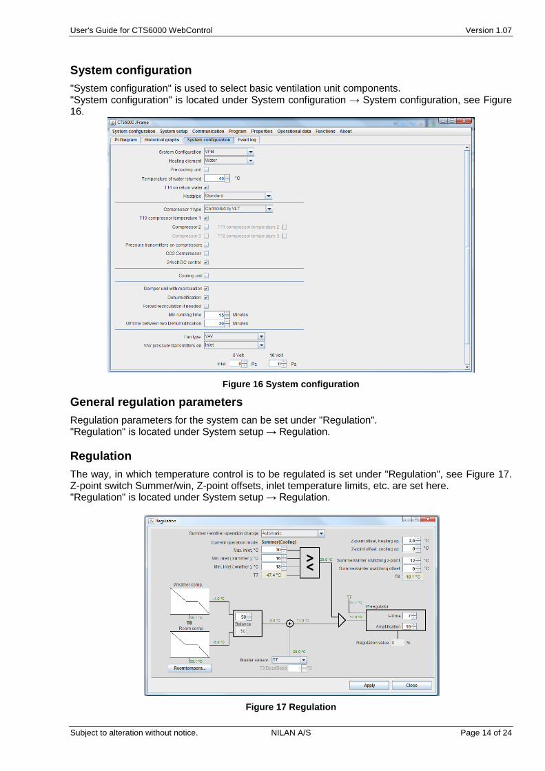
System configuration
"System configuration" is used to select basic ventilation unit components. "System configuration" is located under System configuration → System configuration, see Figure 16.
Figure 16 System configuration
General regulation parameters
Regulation parameters for the system can be set under "Regulation". "Regulation" is located under System setup → Regulation.
Regulation
The way, in which temperature control is to be regulated is set under "Regulation", see Figure 17. Z-point switch Summer/win, Z-point offsets, inlet temperature limits, etc. are set here. "Regulation" is located under System setup → Regulation.
Figure 17 Regulation
User's Guide for CTS6000 WebControl Version 1.07
Subject to alteration without notice. NILAN A/S Page 15 of 24
Filter monitor
The filters located in the fresh air intake and exhaust ducts gradually become dirty. This can be recorded in several ways. "Filter guard" is located under System setup → Filter guard.
Component priority
If the unit is equipped with an after-heating coil, it may be beneficial to utilize the coil before activating the heat pump in situations where heating is required. The order can be changed under "Component priority". "Component priority" is located under System configuration → Component priority.
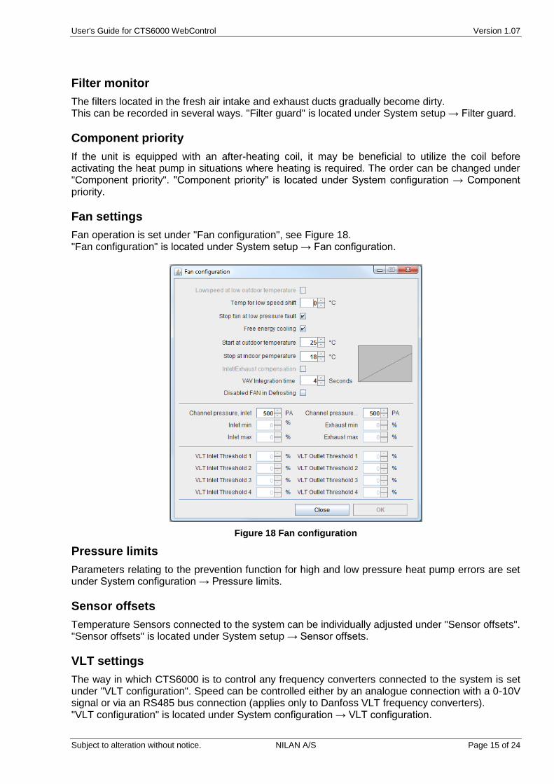
Fan settings
Fan operation is set under "Fan configuration", see Figure 18. "Fan configuration" is located under System setup → Fan configuration.
Figure 18 Fan configuration
Pressure limits
Parameters relating to the prevention function for high and low pressure heat pump errors are set under System configuration → Pressure limits.
Sensor offsets
Temperature Sensors connected to the system can be individually adjusted under "Sensor offsets". "Sensor offsets" is located under System setup → Sensor offsets.
VLT settings
The way in which CTS6000 is to control any frequency converters connected to the system is set under "VLT configuration". Speed can be controlled either by an analogue connection with a 0-10V signal or via an RS485 bus connection (applies only to Danfoss VLT frequency converters). "VLT configuration" is located under System configuration → VLT configuration.
User's Guide for CTS6000 WebControl Version 1.07
Subject to alteration without notice. NILAN A/S Page 16 of 24
VLT parameters
If the frequency converters connected to the system are controlled via an RS485 bus connection, it is possible to view and alter their parameters. "VLT parameters" is located under System setup → VLT parameters.
NETR unit settings
The ventilation unit can communicate with room temperature controllers via Netavent. These are added under System configuration → NETR units.
Programming
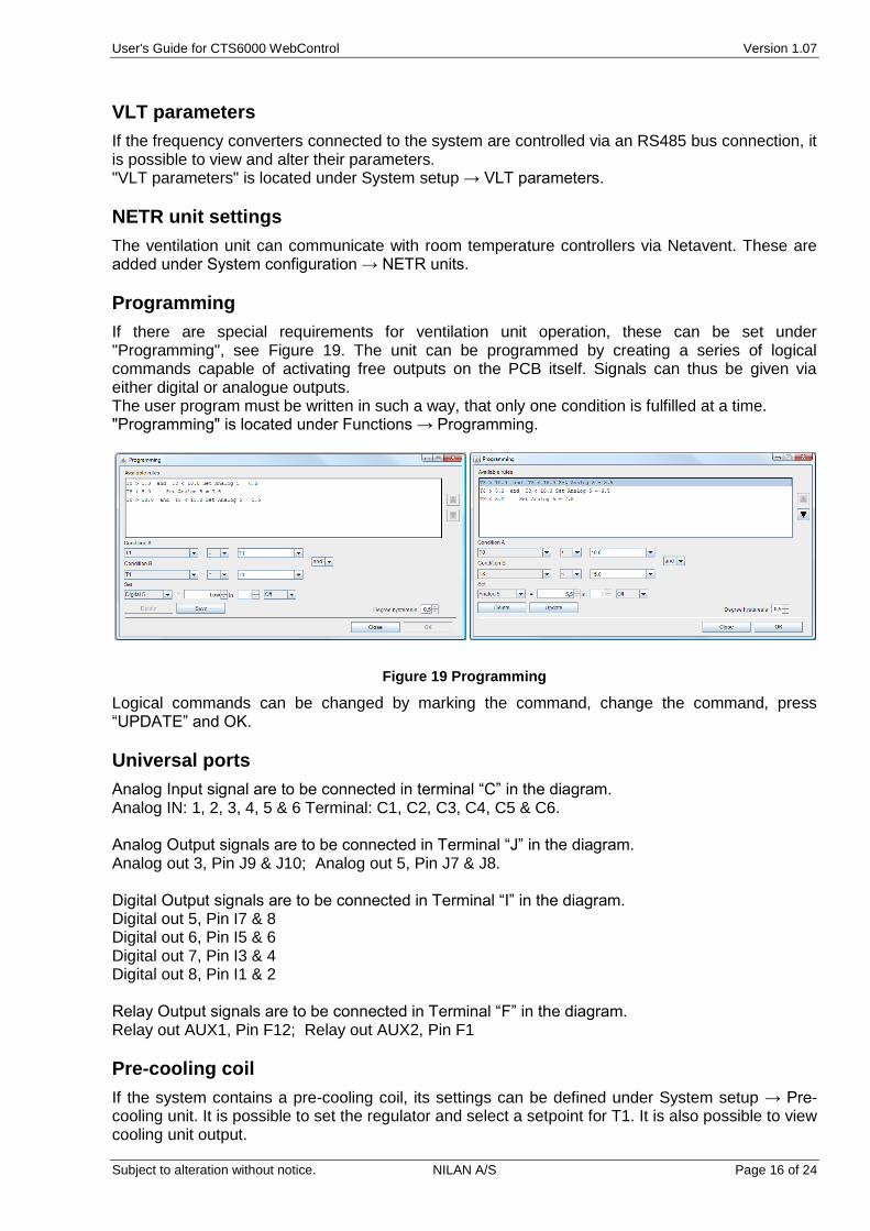
If there are special requirements for ventilation unit operation, these can be set under "Programming", see Figure 19. The unit can be programmed by creating a series of logical commands capable of activating free outputs on the PCB itself. Signals can thus be given via either digital or analogue outputs. The user program must be written in such a way, that only one condition is fulfilled at a time. "Programming" is located under Functions → Programming.
Figure 19 Programming
Logical commands can be changed by marking the command, change the command, press “UPDATE” and OK.
Universal ports
Analog Input signal are to be connected in terminal “C” in the diagram. Analog IN: 1, 2, 3, 4, 5 & 6 Terminal: C1, C2, C3, C4, C5 & C6. Analog Output signals are to be connected in Terminal “J” in the diagram. Analog out 3, Pin J9 & J10; Analog out 5, Pin J7 & J8. Digital Output signals are to be connected in Terminal “I” in the diagram. Digital out 5, Pin I7 & 8 Digital out 6, Pin I5 & 6 Digital out 7, Pin I3 & 4 Digital out 8, Pin I1 & 2 Relay Output signals are to be connected in Terminal “F” in the diagram. Relay out AUX1, Pin F12; Relay out AUX2, Pin F1
Pre-cooling coil
If the system contains a pre-cooling coil, its settings can be defined under System setup → Pre-cooling unit. It is possible to set the regulator and select a setpoint for T1. It is also possible to view cooling unit output.
User's Guide for CTS6000 WebControl Version 1.07
Subject to alteration without notice. NILAN A/S Page 17 of 24
Network settings
Network configuration
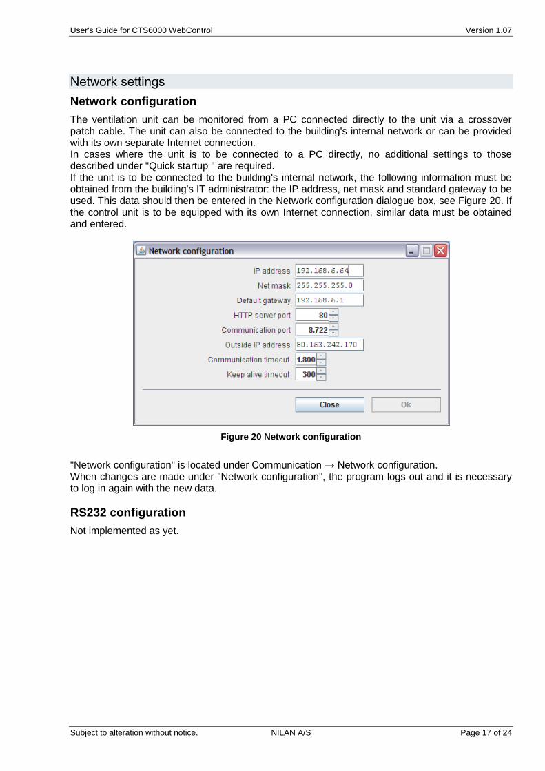
The ventilation unit can be monitored from a PC connected directly to the unit via a crossover patch cable. The unit can also be connected to the building's internal network or can be provided with its own separate Internet connection. In cases where the unit is to be connected to a PC directly, no additional settings to those described under "Quick startup " are required. If the unit is to be connected to the building's internal network, the following information must be obtained from the building's IT administrator: the IP address, net mask and standard gateway to be used. This data should then be entered in the Network configuration dialogue box, see Figure 20. If the control unit is to be equipped with its own Internet connection, similar data must be obtained and entered.
Figure 20 Network configuration
"Network configuration" is located under Communication → Network configuration. When changes are made under "Network configuration", the program logs out and it is necessary to log in again with the new data.
RS232 configuration
Not implemented as yet.
User's Guide for CTS6000 WebControl Version 1.07
Subject to alteration without notice. NILAN A/S Page 18 of 24
RS485 configuration
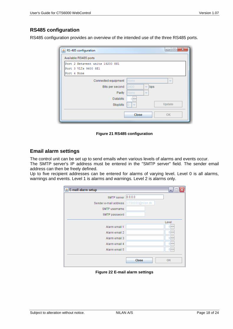
RS485 configuration provides an overview of the intended use of the three RS485 ports.
Figure 21 RS485 configuration
Email alarm settings
The control unit can be set up to send emails when various levels of alarms and events occur. The SMTP server's IP address must be entered in the "SMTP server" field. The sender email address can then be freely defined. Up to five recipient addresses can be entered for alarms of varying level. Level 0 is all alarms, warnings and events. Level 1 is alarms and warnings. Level 2 is alarms only.
Figure 22 E-mail alarm settings

User's Guide for CTS6000 WebControl Version 1.07
Subject to alteration without notice. NILAN A/S Page 19 of 24
Appendices
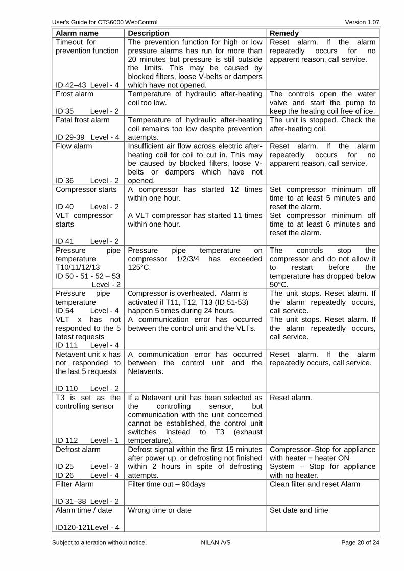
Description of alarms
Alarm name Description Remedy
Door open ID 32 Level - 4
Door to fans is open. Ventilation unit stops in order to prevent personal injury.
Close door and reset alarm.
Fire alarm ID 33 Level - 4
The unit is equipped with two fire thermostats: one in the inlet duct, the other in the exhaust duct. If temperature becomes excessive, the thermostats are activated.
Reset fire thermostats in unit and reset alarm.
Smoke alarm ID 30 Level - 4
Smoke detectors can be fitted in the unit. One of these smoke detectors has sensed smoke.
Check smoke detector and reset alarm.
Thermal relay ID 34 Level - 4
Motor protector has cut out; Klixon in compressor motor or fan motor has cut out; or error has occurred in frequency converter.
Reset motor protector or remedy error in frequency converter and reset alarm.
High pressure alarm ID 2 Level - 4
A high pressure alarm can be activated if there is insufficient air flow through the unit. This may be caused by blocked filters, loose V-belts or dampers which have not opened.
Reset alarm. If the alarm repeatedly occurs for no apparent reason, call service.
Low pressure alarm 1 ID 3 – 6 Level - 2
Low pressure alarm 1 can be activated if there is insufficient air flow through the unit. This may be caused by blocked filters, loose V-belts or dampers which have not opened.
The controls stop the compressor itself until the pressure switch is reset. Max. 5 times an hour, however.
Condenser high pressure ID 8 – 11 Level - 4
Upper limit(2) for cooling circuit pressure set under "Pressure limits" has been exceeded. The alarm can be activated by insufficient air flow through the unit. This may be caused by blocked filters, loose V-belts or dampers which have not opened.
Reset alarm. If the alarm repeatedly occurs for no apparent reason, call service.
Evaporator low pressure 1 ID 9 – 12 Level - 3
Lower limit(2) for cooling circuit pressure, which is set under "Pressure limits", has been exceeded. The alarm can be activated by insufficient air flow through the unit. This may be caused by blocked filters, loose V-belts or dampers which have not opened.
The controls stop the compressor until pressure is regained. Max. 5 times an hour, however.
Evaporator low pressure 2 ID 10–13 Level - 4
Evaporator low pressure 2 is activated if Evaporator low pressure 1 has been activated 5 times within the last hour.
Reset alarm. If the alarm repeatedly occurs for no apparent reason, call service.
Condenser overheated ID 20 Level - 4
Condenser temperature (T5) setting under "Pressure limits" too high. The alarm can be activated by insufficient air flow through the unit. This may be caused by blocked filters, loose V-belts or dampers which have not opened.
Reset alarm. If the alarm repeatedly occurs for no apparent reason, call service.
Evaporator too cold ID 21 Level - 4
Evaporator temperature (T6) setting under "Pressure limits" too low. The alarm can be activated by insufficient air flow through the unit. This may be caused by blocked filters, loose V-belts or dampers which have not opened.
Reset alarm. If the alarm repeatedly occurs for no apparent reason, call service.
User's Guide for CTS6000 WebControl Version 1.07
Subject to alteration without notice. NILAN A/S Page 20 of 24
Alarm name Description Remedy
Timeout for prevention function ID 42–43 Level - 4
The prevention function for high or low pressure alarms has run for more than 20 minutes but pressure is still outside the limits. This may be caused by blocked filters, loose V-belts or dampers which have not opened.
Reset alarm. If the alarm repeatedly occurs for no apparent reason, call service.
Frost alarm ID 35 Level - 2
Temperature of hydraulic after-heating coil too low.
The controls open the water valve and start the pump to keep the heating coil free of ice.
Fatal frost alarm ID 29-39 Level - 4
Temperature of hydraulic after-heating coil remains too low despite prevention attempts.
The unit is stopped. Check the after-heating coil.
Flow alarm ID 36 Level - 2
Insufficient air flow across electric after-heating coil for coil to cut in. This may be caused by blocked filters, loose V-belts or dampers which have not opened.
Reset alarm. If the alarm repeatedly occurs for no apparent reason, call service.
Compressor starts ID 40 Level - 2
A compressor has started 12 times within one hour.
Set compressor minimum off time to at least 5 minutes and reset the alarm.
VLT compressor starts ID 41 Level - 2
A VLT compressor has started 11 times within one hour.
Set compressor minimum off time to at least 6 minutes and reset the alarm.
Pressure pipe temperature T10/11/12/13 ID 50 - 51 - 52 – 53
Level - 2
Pressure pipe temperature on compressor 1/2/3/4 has exceeded 125°C.
The controls stop the compressor and do not allow it to restart before the temperature has dropped below 50°C.
Pressure pipe temperature ID 54 Level - 4
Compressor is overheated. Alarm is activated if T11, T12, T13 (ID 51-53) happen 5 times during 24 hours.
The unit stops. Reset alarm. If the alarm repeatedly occurs, call service.
VLT x has not responded to the 5 latest requests ID 111 Level - 4
A communication error has occurred between the control unit and the VLTs.
The unit stops. Reset alarm. If the alarm repeatedly occurs, call service.
Netavent unit x has not responded to the last 5 requests ID 110 Level - 2
A communication error has occurred between the control unit and the Netavents.
Reset alarm. If the alarm repeatedly occurs, call service.
T3 is set as the controlling sensor ID 112 Level - 1
If a Netavent unit has been selected as the controlling sensor, but communication with the unit concerned cannot be established, the control unit switches instead to T3 (exhaust temperature).
Reset alarm.
Defrost alarm ID 25 Level - 3 ID 26 Level - 4
Defrost signal within the first 15 minutes after power up, or defrosting not finished within 2 hours in spite of defrosting attempts.
Compressor–Stop for appliance with heater = heater ON System – Stop for appliance with no heater.
Filter Alarm ID 31–38 Level - 2
Filter time out – 90days Clean filter and reset Alarm
Alarm time / date ID120-121Level - 4
Wrong time or date Set date and time
User's Guide for CTS6000 WebControl Version 1.07
Subject to alteration without notice. NILAN A/S Page 21 of 24
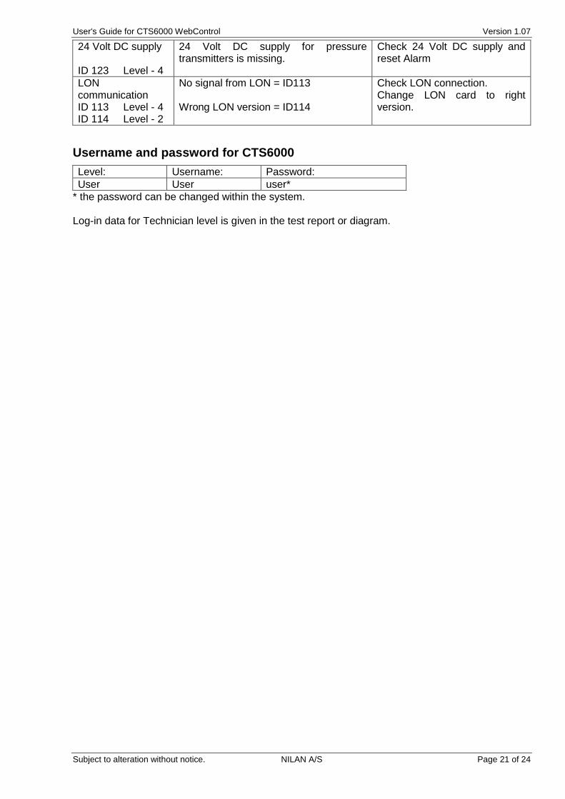
24 Volt DC supply ID 123 Level - 4
24 Volt DC supply for pressure transmitters is missing.
Check 24 Volt DC supply and reset Alarm
LON communication ID 113 Level - 4 ID 114 Level - 2
No signal from LON = ID113 Wrong LON version = ID114
Check LON connection. Change LON card to right version.
Username and password for CTS6000
Level: Username: Password:
User User user*
* the password can be changed within the system. Log-in data for Technician level is given in the test report or diagram.

User's Guide for CTS6000 WebControl Version 1.07
Subject to alteration without notice. NILAN A/S Page 22 of 24
Description of sensors and components
Sensor/component Description
Temperature sensor T1 Inlet sensor after heat pipe
T2 Inlet sensor after heat pump
T3 Exhaust sensor
T4 Discharge sensor
T5 Upper evaporator/condenser sensor
T6 Lower evaporator/condenser sensor
T7 Inlet sensor after inlet fan and after-heating coil (if any)
T8 Fresh air sensor
T9 Sensor in hydronic after-heating coil
T10 Pressure pipe sensor compressor 1
T11 Pressure pipe sensor compressor 2
T12 Pressure pipe sensor compressor 3
T13 Pressure pipe sensor compressor 4-5-6 (extern cooling unit)
T14 Temperature return water aux. heater
T15 Unused
T16 Unused
Tpanel (T17) Temperature sensor in control panel
Sensors Air flow in Air flow sensor in inlet duct
Air flow out Sensor for measuring air flow in exhaust duct
Humidity sensor Air humidity sensor in ventilated area
Pressure transmitter inlet Air pressure sensor in inlet duct
Pressure transmitter exhaust Air pressure sensor in exhaust duct
Pressure transmitter intake filter Sensor for measuring pressure drop across fresh air intake filter
Pressure transmitter exhaust filter Sensor for measuring pressure drop across exhaust filter
Pressure transmitter high pressure
Sensor for measuring pressure-side pressure in cooling circuit of main module
Pressure transmitter low pressure Sensor for measuring suction-side pressure in cooling circuit of main module
Pressure transmitter high pressure cooling module
Sensor for measuring pressure-side pressure in cooling circuit of cooling module
Pressure transmitter low pressure cooling module
Sensor for measuring suction-side pressure in cooling circuit of cooling module
Active components Compressors 1-3 Compressors in main unit
Compressors 4-6 Compressors in cooling module
Fan in Inlet fan
Fan out Exhaust fan
Bypass valve cooling Hot gas bypass valve, cooling
Bypass valve heating Hot gas bypass valve, heating
Modulating hot gas bypass valve Modulating hot gas bypass valve, in both cooling and heating
Four-way valve Valve for switching heat pump status between heating and cooling
Electric heating coil 7-step electric after-heating coil
Water valve Modulating water valve in hydronic after-heating coil
Water pump Circulation pump for hydronic after-heating coil
Damper in Shut-off damper in inlet duct
Damper out Shut-off damper in exhaust duct
Damper recirculation Damper for exhaust air recirculation
Damper supplementary Supplementary damper in exhaust duct
Passive components Heat pipe Passive heat recovery
User's Guide for CTS6000 WebControl Version 1.07
Subject to alteration without notice. NILAN A/S Page 23 of 24
Network settings on PC with Windows
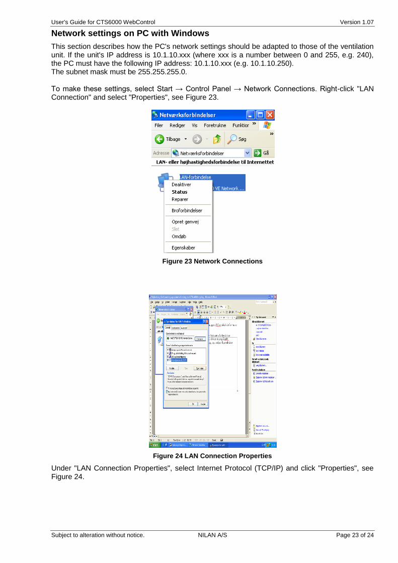
This section describes how the PC's network settings should be adapted to those of the ventilation unit. If the unit's IP address is 10.1.10.xxx (where xxx is a number between 0 and 255, e.g. 240), the PC must have the following IP address: 10.1.10.xxx (e.g. 10.1.10.250). The subnet mask must be 255.255.255.0. To make these settings, select Start → Control Panel → Network Connections. Right-click "LAN Connection" and select "Properties", see Figure 23.
Figure 23 Network Connections
Figure 24 LAN Connection Properties
Under "LAN Connection Properties", select Internet Protocol (TCP/IP) and click "Properties", see Figure 24.

User's Guide for CTS6000 WebControl Version 1.07
Subject to alteration without notice. NILAN A/S Page 24 of 24
Under "Internet Protocol (TCP/IP) Properties", select the "Alternative Configuration" tab, enter 10.1.10.250 in the IP address field and 255.255.255.0 in the subnet mask field, click "OK" and then "Close", see Figure 25.
Figure 25 Internet Protocol (TCP/IP) Properties
Note! When logging into a ventilation unit from a PC connected directly to the unit via a crossover patch cable, it will take a while after connecting the cable before the PC has registered that it is to choose the IP address entered under "Alternative Configuration".
Creating a separate xDSL connection
The following example illustrates how a separate ADSL connection can be created for the control unit. Contact your Internet Provider and order an ADSL connection for the address at which the unit is installed. The following must be included in the order:
- Static IP address - Port 8722 must be open for normal traffic
Once the connection has been activated, the control unit's network settings must be changed. To do so, log into the system from a PC connected directly to the control unit with a crossover cable as described in section 0. Then enter the following data under Communication → Network settings:
- IP address : 192.168.1.3 (LAN IP address) - Net mask : 255.255.255.0 - Standard gateway : 192.168.1.1 (Router IP address)
Click OK to save and log out. The control unit can now be connected to the router using a standard patch cable. This completes the setup, and the ventilation unit can be accessed from anywhere by entering the static IP address (WAN IP address) assigned by your Internet Provider in the address field of an Internet browser. For service purposes, it is possible to log into the system by connecting a computer to one of the other outputs on the router. Technicians can then log into the control unit by entering the LAN IP address in the address field of an Internet browser. To activate email alarms, the SMTP server IP address must be entered in the field in the email alarm settings window. Then enter a fictive email address as the unit's email address. Leave the username and password fields empty.