users guide and maintenance manual mitsubishi diesel ... · this manual contains information for...
TRANSCRIPT
Mitsubishi Diesel engine
S 12 R
Users guide and maintenance manual
Pub.No.
INTRODUCTIONThis manual contains information for operation, inspection and maintenance of the Mitsubishi Engines.
Please read this manual carefully to understand the operation, inspection and maintenance procedures in order to use the engine properly.
Failure to follow directions in this manual can lead to serious accidents.
99240-32120
INTRODUCTION
Limited WarrantyThe manufacturer, at its option, will repair or replace any parts returned intact to the manufacturer only when the manufacturer, upon inspection, determines to be defective in material and/or workmanship.The foregoing shall constitute the limited warranty provided by the manufacturer.The manufacturer will provide the limited warranty only to the user with whom the manufacturer concludes the original contract, and shall not provide the limited warranty to a user to whom the ownership of the product may be transferred.
• The manufacturer makes no warranties, either express or implied, except as provided in this manual, includ-ing without limitation thereof, warranties as to marketability, merchantability, fitness for a particular purpose or use, or against infringement of any patent.
• The manufacturer will not be liable for any damages or consequential damages, including without limitation thereof, damages or other costs resulting from any abuse, misuse, misapplication of the engine and devices supplied by the manufacturer.
• The manufacturer will not be liable for any damages or personal injuries resulting from any modification, without the manufacturer's written permission, of the engine and devices supplied by the manufacturer.
• The manufacturer will not be liable for any damages or production losses caused by the use of fuel, engine oil and/or long life coolant that are not recommended by the manufacturer.

INTRODUCTION
Important Information• To avoid potential hazard, accident prevention
activities must be planned methodically and con-ducted continually by considering all aspects of engine operation, maintenance and inspection.Everyone including managers and supervisors should actively participate, recognize one's role and organize oneself and one's work to ensure a safe environment.
• The foremost safety objective is to prevent acci-dents which could result in injury or death, or damage equipment.
• Observe all related federal/national and local codes and regulations to reduce the possibility of personal injury.
• The manufacturer cannot foresee all potential danger of the engine, potential danger resulting from human error and others, or danger caused by a specific environment in which the engine is used.Since there are many actions that cannot be per-formed or must not be performed, it is not possi-ble to indicate every caution in this manual or on warning labels. As such, it is extremely important to follow directions in this manual and also to take general safety measures when operating, main-taining and inspecting the engine.
• This manual has been prepared for people whose native language is English. When the engine is used by individuals whose native language is not English, the customer is requested to provide thorough safety guidance to the operators. Also add safety, caution and operating signs that describe the original warning label statements in the native language of the operators.
• The engine must be operated, maintained and inspected only by qualified persons who have thorough knowledge of engines and their danger and also received danger avoidance training.
• To prevent occurrence of an accident, do not attempt to carry out any operation other than those described in this manual, or to use the engine for any unapproved purpose.
• When the ownership of the engine is transferred, be sure to provide this manual with the engine to the new owner. Also inform the manufacturer of
the name and address of the new owner of the engine.
• This manual is copyrighted and all rights are reserved. The drawings and technical reference, including this manual, may not, in whole or in part, be duplicated, photocopied, translated, or reproduced in any electronic medium or machine readable form without prior written consent from the manufacturer.
• The contents in this manual are subject to change without notice for improvement of the engine.
• Your engine may differ from the photographs and figures in this manual.Please note that, depending on specifications, items described in this manual may differ from those on your engine in shape, or may not be installed on your engine.
• If you need more detailed information or have questions, contact a Mitsubishi dealer.
• If this manual is misplaced, obtain a new copy from a Mitsubishi dealer as soon as possible.
INTRODUCTION
WarningsThe following two methods are used to call the attention of the operators and maintenance personnel to the potential danger of the engine.• Warning statements in the manual• Warning labels affixed on the engine
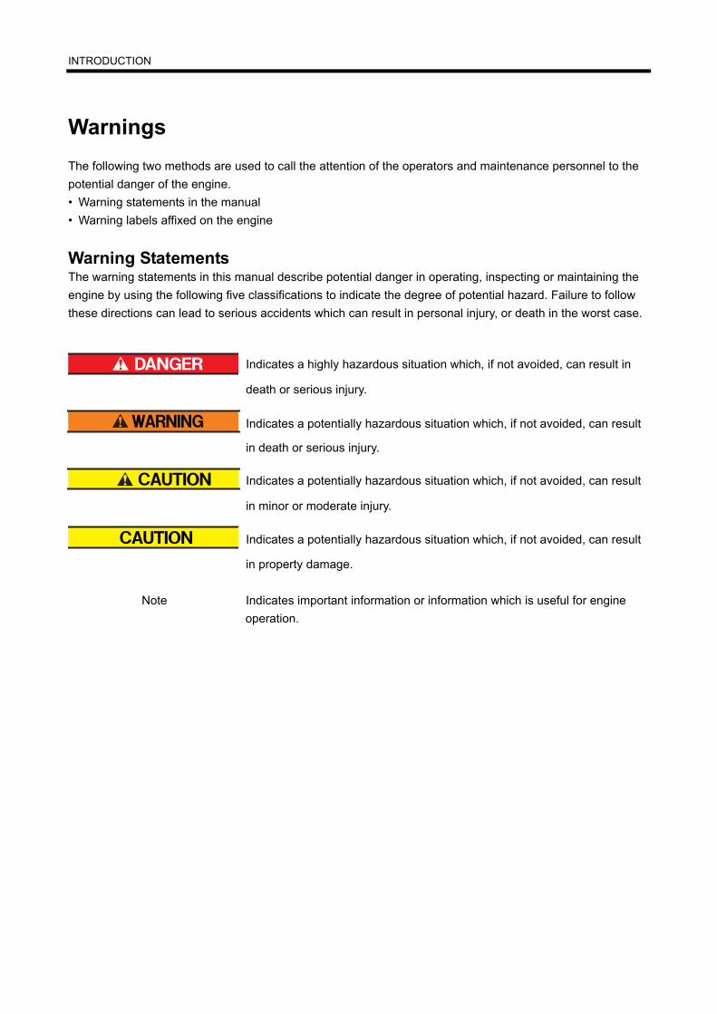
Warning StatementsThe warning statements in this manual describe potential danger in operating, inspecting or maintaining the engine by using the following five classifications to indicate the degree of potential hazard. Failure to follow these directions can lead to serious accidents which can result in personal injury, or death in the worst case.
Indicates a highly hazardous situation which, if not avoided, can result in
death or serious injury.
Indicates a potentially hazardous situation which, if not avoided, can result
in death or serious injury.
Indicates a potentially hazardous situation which, if not avoided, can result
in minor or moderate injury.
Indicates a potentially hazardous situation which, if not avoided, can result
in property damage.
Note Indicates important information or information which is useful for engine operation.

INTRODUCTION
Explanation of Terms
Abbreviations, Standards and Others• API = American Petroleum Institute• ASTM = American Society for Testing and Materials• JIS = Japanese Industrial Standards• MIL = Military Specifications and Standards (U.S.)• MSDS = Material Safety Data Sheet• SAE = Society of Automotive Engineers (U.S.)• LLC = Long Life Coolant
Units of MeasurementMeasurements are based on the International System of Units (SI), and they are converted to the metric sys-tem units in this manual based on the following conversion rates.
• Pressure: 1 MPa = 10.197 kgf/cm2
• Torque: 1 N⋅m = 0.10197 kgf⋅m• Force: 1 N = 0.10197 kgf• Horsepower: 1 kW = 1.341 HP = 1.3596 PS• Meter of mercury: 1 kPa = 0.7 cmHg• Meter of water: 1 kPa = 10.197 cmH2O (cmAq)• Engine speed: 1 min-1 = 1 rpm

CONTENTSChapter 1 BASIC SAFETY PRECAUTIONSWarning Fire and Explosion ...............1-1Keep flames away............................................ 1-1
Keep engine and surrounding area clean ........ 1-1
Never open crankcase until engine cools ........ 1-1
Check for fuel, oil and exhaust gas leaks......... 1-1
Use flameproof light ......................................... 1-1
Do not short electrical wires ............................. 1-1
Keep fire extinguishers and first-aid kit nearby 1-1
Warning Stay Clear of All Rotating and Moving Parts........................................1-2Install protective covers on rotating parts......... 1-2
Check surrounding area for safety ................... 1-2
Stay clear of all rotating and moving parts while en-
gine is operating............................................... 1-2
Lock out and Tag out ....................................... 1-2
Always stop engine before inspection and mainte-
nance ............................................................... 1-2
Always return turning tools to original position. 1-2
Warning Be Careful of Burns..............1-3Do not touch engine during operation or immediate-
ly after operation .............................................. 1-3
Open radiator filler cap carefully ...................... 1-3
Add coolant only after coolant temperature
drops ................................................................ 1-3
Do not dismount heat protection covers........... 1-3
Warning Be Careful of Exhaust Fume Poi-soning..................................................1-3Perform engine operation in a well-ventilated
site ................................................................... 1-3
Warning Protect Ears from Noises .....1-3Wear earplugs.................................................. 1-3
Warning Be Careful When Lifting Engine .................................................1-4Lifting engine carefully ..................................... 1-4
Do not climb onto engine ................................. 1-4
Always watch your footing................................ 1-4
Caution Be Careful of Handling Engine Oil and LLC...............................................1-4
Use only specified fuel, engine oil and
coolant (LLC).................................................... 1-4
Handle LLC carefully ........................................ 1-4
Properly dispose of drained oil and LLC .......... 1-4
Caution Service Battery ..................... 1-5Handle battery carefully ................................... 1-5
Caution When Abnormality Occurs.... 1-5If engine overheats, conduct cooling operation be-
fore stopping engine......................................... 1-5
If engine stops due to abnormality, exercise caution
when restarting................................................. 1-5
If engine oil pressure drops, stop engine immediate-
ly....................................................................... 1-5
If V-belt breaks, stop engine immediately ........ 1-5
Caution Other Cautions ..................... 1-6Never modify engine ........................................ 1-6
Never break seals ............................................ 1-6
Perform all specified pre-operation inspections and
periodic inspections.......................................... 1-6
Perform engine break-in................................... 1-6
Warm up engine before use............................. 1-6
Never operate engine under overload condition1-6
Conduct cooling operation before stopping
engine .............................................................. 1-6
Do not splash water on engine......................... 1-6
Conduct proper maintenance of air cleaner ..... 1-7
Observe safety rules at workplace ................... 1-7
Wear proper work clothes and protective gear. 1-7
Use appropriate tools for maintenance work.... 1-7
Do not operate starter for prolonged time ........ 1-7
Do not turn off battery switch while engine is operat-
ing .................................................................... 1-7
Cautions concerning transportation ................. 1-7
Caution About Warning Labels .......... 1-8Maintain and inspect warning labels ................ 1-8
Chapter 2 NAME OF PARTSEngine External Diagrams .................. 2-1Left View .......................................................... 2-1
Contents-1
CONTENTS
Right View........................................................ 2-1
Equipment and Instrument ..................2-2Starting and Shutdown Devices ....................... 2-2Manual stop lever ..................................................... 2-2
Stop Solenoid ........................................................... 2-2
Oil Pressure Unit....................................................... 2-3
Thermo Unit .............................................................. 2-3
Revolution Detection Pickup..................................... 2-3
Engine Protection Devices ..................2-4Oil Pressure Switch .................................................. 2-4
Oil Filter Alarm Switch .............................................. 2-4
Thermo Switch.......................................................... 2-4
Air Cleaner Indicator ................................................. 2-5
Using Turning Gear.......................................... 2-6
Chapter 3 OPERATIONPreparation for Operation of New or Over-hauled Engine......................................3-1Fuel System ..................................................... 3-1Pouring fuel............................................................... 3-1
Bleed the fuel system ............................................... 3-2
Fuel filters ................................................................. 3-2
Fuel injection pump................................................... 3-2
Priming pump cap tightening method ....................... 3-3
Lubricating System........................................... 3-4Pouring engine oil ..................................................... 3-4
Cooling System................................................ 3-5Pouring coolant......................................................... 3-5
Checking Battery.............................................. 3-6Electrolyte level......................................................... 3-6
Checking specific gravity of electrolyte..................... 3-6
Test Operation ................................................. 3-7Starting and stopping................................................ 3-7
Inspection ................................................................. 3-7
Normal Engine Operation....................3-8Preparations for
Operation (Pre-Start Inspection) ...................... 3-8External Inspection ................................................... 3-8
Draining Water from Fuel Tank........................ 3-9Checking Engine Oil Level........................................ 3-9
Checking Coolant Level.......................................... 3-10
Inspection of the air cleaner indicator ..................... 3-10
Inspection of Air Tank Air Pressure ........................ 3-11
Starting.............................................. 3-12Warming-up Operation................................... 3-12During warming-up operation ..................................3-12
External inspection during warming-up....................3-12
Operation ....................................................... 3-13Inspection during operation .....................................3-13
Stopping ......................................................... 3-14
Emergency Stop............................................. 3-14
Inspection After Stopping ............................... 3-14
Chapter 4 MAINTENANCECautions Concerning Maintenance..... 4-1Stop the engine before checking or adding fuel, oil or cool-
ant..............................................................................4-1
Handle electrolyte carefully........................................4-1
Handle LLC carefully. ................................................4-1
Always wear protective gear......................................4-1
Use recommended fuel, engine oil and coolant.........4-1
Perform all specified pre-start inspections and periodic in-
spections....................................................................4-1
Use only genuine Mitsubishi parts. ............................4-1
Fuel ..................................................... 4-2Recommended Fuel ......................................... 4-2
Handling Fuel ................................................... 4-2
Engine Oil ........................................... 4-4Recommended Engine Oil ............................... 4-4Selection of Oil Viscosity ...........................................4-4
Handling Engine Oil ......................................... 4-4
Coolant................................................ 4-5Recommended Coolant ................................... 4-5
Long Life Coolant (LLC) ................................... 4-5
Recommended LLC ......................................... 4-6
Features and Performance of
Recommended LLC ......................................... 4-6
Maintenance of LLC ......................................... 4-6Replacement timing of LLC .......................................4-6
LLC concentration......................................................4-6
Importance of LLC............................................ 4-7
Characteristics of LLC Additive and Important
Notes................................................................ 4-7
Examples of Abnormalities Caused by LLC..... 4-7Pitting on iron parts....................................................4-7
Contents-2

CONTENTS
Corrosion of aluminum parts..................................... 4-7
Pitting and clogging of radiator ................................. 4-7
Filters...................................................4-8Electrical Parts.....................................4-8Cautions in Operating Engine in Cold Weather Season..................................4-9Fuel .................................................................. 4-9
Engine Oil......................................................... 4-9
Coolant............................................................. 4-9
Battery.............................................................. 4-9
Maintenance After Cold Season ...................... 4-9
Chapter 5 PERIODIC MAINTENANCE CHARTHow to Use Periodic Maintenance Chart....................................................5-1Periodic Maintenance Chart............................. 5-1Periodic maintenance chart for regular-use engine .. 5-1
Periodic maintenance chart for emergency engine .. 5-1
Periodic maintenance chart for general-purpose
engine ....................................................................... 5-1
General Definition of Regular-Use Engine, Emer-
gency Engine and General-Purpose
Engine.............................................................. 5-2General definition of regular-use engine................... 5-2
General definition of emergency engine ................... 5-2
General definition of general-purpose engine........... 5-2
Periodic Maintenance Chart for Engine in Regular Use.........................................5-3Periodic Maintenance Chart for Emergency Engine .................................................5-5Periodic Maintenance Chart for General-Purpose Power Supply Engine............5-8
Chapter 6 PERIODIC INSPECTION AND MAINTENANCE PROCEDURESExternal View.......................................6-1External Inspection........................................... 6-1
Inspection of V-belt and Adjustment of
Belt Tension ..................................................... 6-2Inspecting the V-belt ................................................. 6-2
Adjusting the V-belt tension (Alternator side) ........... 6-2
Adjusting the V-belt tension (Water pump side) ....... 6-2
Inspection of Damper ....................................... 6-3External inspection of damper ...................................6-3
Damper temperature management............................6-3
Fuel System........................................ 6-4Inspection of Fuel Control Linkage Ball Joints . 6-4
Cleaning Fuel Tank .......................................... 6-4
Changing Fuel Filters ....................................... 6-5
Lubricating System ............................. 6-6Changing Engine Oil, Oil Filters and Bypass Oil Fil-
ter ..................................................................... 6-6Draining engine oil .....................................................6-6
Changing oil filters and bypass oil filter .....................6-6
Pouring engine oil ......................................................6-7
Inspection of Engine Oil for Mixing of Fuel and Wa-
ter ..................................................................... 6-7
Changing Governor Oil Filter ........................... 6-8
Cooling System................................... 6-9Changing Coolant ............................................ 6-9Draining coolant.........................................................6-9
Cleaning the cooling system......................................6-9
Pouring coolant........................................................6-10
Inspection and Cleaning Radiator Fins .......... 6-10
Inlet Exhaust System ........................ 6-11Inspection of Turbocharger ............................ 6-11
Draining Water From Exhaust Muffler ............ 6-11
Cleaning Pre-Cleaner..................................... 6-11
Cleaning and Inspecting Air Cleaner Element 6-12
Electrical System .............................. 6-13Inspection of Starters ..................................... 6-13
Inspection of Alternator .................................. 6-13
Checking Battery............................................ 6-14Electrolyte level........................................................6-14
Checking specific gravity of electrolyte....................6-14
Air Starter System............................. 6-15Draining Water and Cleaning Air Starter
Strainer........................................................... 6-15
Draining Water from Air Tank......................... 6-15
Inspection Safety Valve of Air Tank ............... 6-15
Draining Water from Air Starter Compressor . 6-16
Chapter 7 LONG-TERM STORAGELong-term storage............................... 7-1
Contents-3

CONTENTS
Storing Engine in Non-operable Condition for More
Than 3 Months ................................................. 7-1Preparation for Storage ............................................ 7-1
Maintenance during Storage..................................... 7-1
Using Engine after Storage....................................... 7-2
Starting the engine.................................................... 7-2
Storing Engine in Operable Condition for More Than
3 Months .......................................................... 7-2Operating Engine for Maintenance Purposes........... 7-2
Chapter 8 TRANSPORTATIONLifting Engine Carefully .................................... 8-1
Chapter 9 TROUBLESHOOTINGGeneral Precautions............................9-1Contact a Mitsubishi Dealer for Repair Service 9-1
Examination before Work................................. 9-1
Notes Regarding Contamination ...................... 9-1
Notes Regarding Parts Handling...................... 9-1
Work Safety...................................................... 9-1
How to Troubleshoot ...........................9-2Starters Do Not Crank or Crank Slowly, Resulting in Start
Failure....................................................................... 9-2
Starters Crank, But Engine Does Not Start .............. 9-2
Other Problems and Countermeasures ........... 9-3Engine Output is Low................................................ 9-3
Exhaust Smoke is White or Blue ............................. 9-3
Exhaust Smoke is Black or Dark Gray...................... 9-4
Fuel Consumption is High......................................... 9-4
Engine Oil Consumption is High ............................... 9-4
Engine Overheats ..................................................... 9-5
Engine Oil Pressure is Faulty ................................... 9-5
When Fuel Has Run Out .................................. 9-5
Chapter 10 MAIN SPECIFICATIONSMain Specifications............................10-1
List of Illustrationsfig.1-1 Warning labels .............................................1-8
fig.2-1 Left view.......................................................2-1
fig.2-2 Right view ....................................................2-1
fig.2-3 Start switch and stop switch.........................2-2
fig.2-4 Manual Stop Lever .......................................2-2
fig.2-5 Stop Solenoid...............................................2-2
fig.2-6 Oil pressure unit ...........................................2-3
fig.2-7 Thermo unit ..................................................2-3
fig.2-8 Revolution Detection Pickup ........................2-3
fig.2-9 Oil pressure switch.......................................2-4
fig.2-10 Oil filter alarm switch....................................2-4
fig.2-11 Thermo switch..............................................2-4
fig.2-12 Air cleaner indicator .....................................2-5
fig.2-13 Turning gear position(Engine in operation) ..2-6
fig.2-14 Turning gear position(Shaft pushed in) ........2-6
fig.2-15 Turning gear position(Turning shaft) ............2-6
fig.3-1 Using the priming pump ...............................3-2
fig.3-2 Fuel filters ....................................................3-2
fig.3-3 Fuel injection pump......................................3-2
fig.3-4 Priming pump cap tightening method...........3-3
fig.3-5 Priming pump cap packing...........................3-3
fig.3-6 Oil filler and oil level gage ............................3-4
fig.3-7 Pouring engine oil on valve mechanisms
and chamber ................................................3-4
fig.3-8 Coolant drain cock on the engine.................3-5
fig.3-9 Coolant drain cock on the water pump.........3-5
fig.3-10 Radiator coolant level...................................3-5
fig.3-11 Coolant level in reserve tank........................3-5
fig.3-12 Inspecting electrolyte level ...........................3-6
fig.3-13 Inspecting specific gravity of electrolyte.......3-6
fig.3-14 Checking valves for open/closed position....3-8
fig.3-15 Draining water from fuel tank .......................3-9
fig.3-16 Oil filler and oil level gage ............................3-9
fig.3-17 Radiator cap...............................................3-10
fig.3-18 Radiator coolant level.................................3-10
fig.3-19 Reserve tank coolant level .........................3-10
fig.3-20 Air cleaner indicator ...................................3-10
fig.3-21 Inspection of air tank air pressure..............3-11
fig.3-22 Manual stop lever.......................................3-14
fig.4-1 Recommended fuel ......................................4-2
fig.4-2 Recommended fuel according to air
temperature..................................................4-2
Contents-4
CONTENTS
fig.4-3 Recommended oil viscosity according to air tem-
perature....................................................... 4-4
fig.6-1 Inspecting the V-belt and adjusting the belt ten-
sion.............................................................. 6-2
fig.6-2 Inspecting the damper................................. 6-3
fig.6-3 Managing the damper temperature............. 6-3
fig.6-4 Inspection of the fuel control linkage for loose-
ness............................................................. 6-4
fig.6-5 Removing the fuel control linkage ............... 6-4
fig.6-6 Cleaning fuel tank ....................................... 6-4
fig.6-7 Changing fuel filters .................................... 6-5
fig.6-8 Fuel filter ..................................................... 6-5
fig.6-9 Oil filters and bypass oil filter ...................... 6-6
fig.6-10 Oil filter ........................................................ 6-6
fig.6-11 Oil filler and oil level gage ........................... 6-7
fig.6-12 Governor oil filter......................................... 6-8
fig.6-13 Changing governor oil filter ......................... 6-8
fig.6-14 Radiator cap................................................ 6-9
fig.6-15 Draining coolant (Engine main parts).......... 6-9
fig.6-16 Draining coolant (Water pump) ................... 6-9
fig.6-17 Radiator..................................................... 6-10
fig.6-18 Reserve tank ............................................. 6-10
fig.6-19 Cleaning radiator fins ................................ 6-10
fig.6-20 Inspection of turbocharger ........................ 6-11
fig.6-21 Draining water from exhaust muffler ......... 6-11
fig.6-22 Cleaning Pre-Cleaner................................ 6-11
fig.6-23 Removing air cleaner element .................. 6-12
fig.6-24 Cleaning air cleaner element .................... 6-12
fig.6-25 Inspecting air cleaner element .................. 6-12
fig.6-26 Air cleaner indicator .................................. 6-12
fig.6-27 Inspection of Starters ................................ 6-13
fig.6-28 Inspection of Alternator ............................. 6-13
fig.6-29 Inspecting electrolyte level ........................ 6-14
fig.6-30 Inspecting specific gravity of electrolyte.... 6-14
fig.6-31 Air starter strainer...................................... 6-15
fig.6-32 Draining water from air tank ...................... 6-15
fig.6-33 Inspection safety valve of air tank ............. 6-15
fig.6-34 Air starter compressor............................... 6-16
fig.8-1 Hangers for lifting ........................................ 8-1
fig.8-2 The center of gravity for the engine ............ 8-1
List of TablesTable 3-1 Specific gravity of electrolyte ...................3-6
Table 4-2 Fuel Use Limit Property Guideline...........4-3
Table 4-3 Water quality standards...........................4-5
Table 4-4 Recommended brands of LLC.................4-6
Table 4-5 Recommended LLC concentration (for refer-
ence only) ................................................4-6
Table 5-1 Periodic Maintenance Chart for Engine in
Regular Use.............................................5-3
Table 5-2 Periodic Maintenance Chart for Emergency
Engine .....................................................5-5
Table 5-3 Periodic Maintenance Chart for General-Pur-
pose Power Supply Engine .....................5-8
Table 6-1 Temperature Management with Thermo
Label........................................................6-3
Table 6-2 Specific gravity of electrolyte .................6-14
Table 7-1 Recommended Rust-preventive
Oil and Corrosion Inhibitor.......................7-1
Table 9-1 Starters Do Not Crank or Crank Slowly, Re-
sulting in Start Failure..............................9-2
Table 9-2 Starters Crank, But Engine Does Not Start9-2
Table 9-3 Engine Output is Low ..............................9-3
Table 9-4 Exhaust Smoke is White or Blue .............9-3
Table 9-5 Exhaust Smoke is Black or Dark Gray ....9-4
Table 9-6 Fuel Consumption is High .......................9-4
Table 9-7 Engine Oil Consumption is High..............9-4
Table 9-8 Engine Overheats....................................9-5
Table 9-9 Engine Oil Pressure is Faulty ..................9-5
Table 10-1 Main Specifications Table......................10-1
Contents-5

Chapter 1 BASIC SAFETY PRECAUTIONS
Warning Fire and Explosion
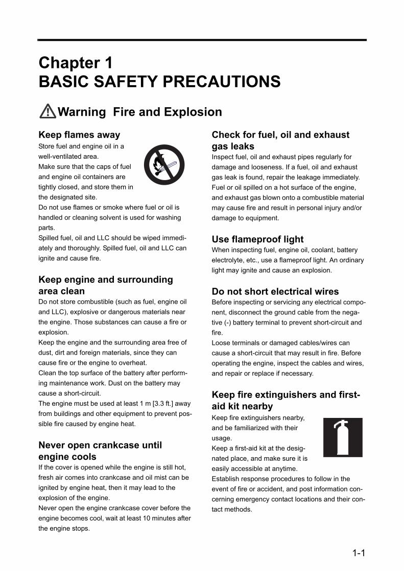
Keep flames awayStore fuel and engine oil in a well-ventilated area.Make sure that the caps of fuel and engine oil containers are tightly closed, and store them in the designated site.Do not use flames or smoke where fuel or oil is handled or cleaning solvent is used for washing parts.Spilled fuel, oil and LLC should be wiped immedi-ately and thoroughly. Spilled fuel, oil and LLC can ignite and cause fire.
Keep engine and surrounding area cleanDo not store combustible (such as fuel, engine oil and LLC), explosive or dangerous materials near the engine. Those substances can cause a fire or explosion.Keep the engine and the surrounding area free of dust, dirt and foreign materials, since they can cause fire or the engine to overheat.Clean the top surface of the battery after perform-ing maintenance work. Dust on the battery may cause a short-circuit.The engine must be used at least 1 m [3.3 ft.] away from buildings and other equipment to prevent pos-sible fire caused by engine heat.
Never open crankcase until engine coolsIf the cover is opened while the engine is still hot, fresh air comes into crankcase and oil mist can be ignited by engine heat, then it may lead to the explosion of the engine.Never open the engine crankcase cover before the engine becomes cool, wait at least 10 minutes after the engine stops.
Check for fuel, oil and exhaust gas leaksInspect fuel, oil and exhaust pipes regularly for damage and looseness. If a fuel, oil and exhaust gas leak is found, repair the leakage immediately.Fuel or oil spilled on a hot surface of the engine, and exhaust gas blown onto a combustible material may cause fire and result in personal injury and/or damage to equipment.
Use flameproof lightWhen inspecting fuel, engine oil, coolant, battery electrolyte, etc., use a flameproof light. An ordinary light may ignite and cause an explosion.
Do not short electrical wiresBefore inspecting or servicing any electrical compo-nent, disconnect the ground cable from the nega-tive (-) battery terminal to prevent short-circuit and fire.Loose terminals or damaged cables/wires can cause a short-circuit that may result in fire. Before operating the engine, inspect the cables and wires, and repair or replace if necessary.
Keep fire extinguishers and first-aid kit nearbyKeep fire extinguishers nearby, and be familiarized with their usage.Keep a first-aid kit at the desig-nated place, and make sure it is easily accessible at anytime.Establish response procedures to follow in the event of fire or accident, and post information con-cerning emergency contact locations and their con-tact methods.
1-1

Chapter 1 BASIC SAFETY PRECAUTIONS
Warning Stay Clear of All Rotating and Moving Parts
Install protective covers on rotat-ing partsMake sure the protective covers of the engine are correctly installed. Repair any damaged or loose covers.When the engine is coupled to other equipment or the radiator, install pro-tective covers on the exposed connecting belt and coupling. Never remove protective covers for rotating parts such as the damper cover, camshaft cover or rocker cover while the engine is operating.
Check surrounding area for safetyBefore starting the engine, check to make sure no one is near the engine and tools are not left on or near the engine. Verbally notify persons within the immediate area when starting the engine.When the starter device is posted with a sign that prohibits startup operation, do not operate the engine.
Stay clear of all rotating and mov-ing parts while engine is operat-ingDo not approach rotating and moving parts (output shaft, flywheel, fan belts and pulleys) of the engine while the engine is in operation.Rotating parts can entangle your body or tools and result in serious injury.Keep items that can be easily entangled by rotating parts away from the engine.If your body or tool contacts rotating and moving parts, serious injury may occur as a result.
Lock out and Tag outBe sure to lock out and tag out before starting inspection and maintenance.Lockout and tagout are effective methods of cutting off machines and equipment from energy sources.To lock out and tag out, pull out the key from the starter switch, turn off the battery switch, and post a tag on the starter switch indicating “Do Not Oper-ate.” The starter key switch should be kept by the person performing the inspection and maintenance.For the air starter system, close the main valve of the air tank, and post a tag indicating “Do Not Open the Valve.”
Always stop engine before inspection and maintenanceBe sure to stop the engine before conducting inspection and maintenance. Never attempt to adjust the engine parts while the engine is running. Conducting inspection and maintenance on an operating engine can result in a serious accident of entanglement by rotating parts.
Always return turning tools to original positionBe sure to remove all turning tools used during maintenance and inspection.Starting the engine with the turning tools inserted or turning gears engaged may not only cause engine damage but personal injury as well.
1-2

Chapter 1 BASIC SAFETY PRECAUTIONS
Warning Be Careful of Burns
Do not touch engine during oper-ation or immediately after opera-tionDo not touch the main and exhaust parts of the engine during operation or immediately after operation to prevent burns.To conduct maintenance and inspection, wait until the engine cools sufficiently as indicated with the temperature gage.
Open radiator filler cap carefullyNever open the radiator filler cap while the engine is operating or immediately after it is stopped.The engine coolant is hot during engine operation and immediately after operation. If the radiator filler cap is opened when the coolant is at operating tem-perature, steam and hot coolant may blow out, causing skin burns as a result.When opening the cap, stop the engine and allow the coolant temperature to drop sufficiently. Cover the cap with a cloth or use thick rubber glove, and then slowly open the cap.When closing the cap, be sure to tighten securely.
Add coolant only after coolant temperature dropsDo not add coolant immediately after the engine stops. Wait until the coolant temperature lowers sufficiently to prevent burns.
Do not dismount heat protection coversThe high-temperature exhaust components are installed with heat protection covers. Do not dis-mount these heat protection covers. If they must be removed during inspection and maintenance, be sure to reinstall them after completing the inspec-tion and maintenance.
Warning Be Careful of Exhaust Fume Poisoning
Perform engine operation in a well-ventilated siteExhaust gas from the engine contains carbon monoxide and other harmful substances.Do not operate the engine in an enclosed area (inside a ware-house, tunnel, etc.) or in a site where all sides are blocked, since exhaust fumes can cause gas poi-soning.If the engine must be operated in an enclosed area, discharge the exhaust gas to the outside and pro-vide adequate ventilation.Connect an exhaust duct to the exhaust pipe to lead exhaust gas to the outside, and make sure exhaust gas does not leak from the duct joints.Make sure the exhaust gas does not blow in the direction of plants or animals.
Warning Protect Ears from Noises
Wear earplugsBe sure to wear earplugs when entering into the engine room. The earplugs can be quite use-ful to protect ears from various engine noises.
1-3

Chapter 1 BASIC SAFETY PRECAUTIONS
Warning Be Careful When Lifting Engine
Lifting engine carefullyTo lift the engine, use slings capa-ble of supporting the weight of the engine.Attach appropriate slings to the hangers on the engine.Keep the engine balanced during lifting by consid-ering the center of gravity of the engine.Keep the angle formed by slings attached to hang-ers within 60°. If the angle exceeds this limit, exces-sive load is applied on the hangers and may damage the hangers.If wire ropes contact the engine, place a cloth or other soft padding to prevent damage to the engine and wire ropes.
Do not climb onto engineNever climb onto the engine.To work on parts located on the upper section, use a ladder, stand, etc.Climbing on the engine can not only damage entire parts, but also cause parts to fall off and result in injury.
Always watch your footingUse a stable work platform to stand on when working on the upper part of the engine and other hard-to-reach places.Standing on a decrepit stand or parts box may result in personal injury.Do not put obstacles on the stand.
Caution Be Careful of Handling Engine Oil and LLC
Use only specified fuel, engine oil and coolant (LLC)Use fuel, oil and LLC specified in this manual, and handle them carefully.Use of any other fuel, oil or LLC, and improper han-dling may cause various engine problems and mal-functions.Obtain the MSDSs issued by the fuel, oil and LLC suppliers, and follow the directions on the MSDSs for proper handling.
Handle LLC carefullyWear safety mask and rubber gloves when han-dling LLC. Avoid contact with skin and eyes to pre-vent personal injury. Should LLC be accidentally swallowed, induce vomiting immediately and seek medical attention. Should LLC enter eyes, flush immediately with plenty of water and seek medical attention. If LLC is spilled on skin or clothes, wash immediately with lot of water.Keep flammable materials away from LLC to pre-vent fire. Never use flames or generate sparks near LLC since flames or sparks can cause fire.Drained LLC is harmful. Do not dispose of into con-ventional sewage. Contact a Mitsubishi dealer for the disposal of drained LLC.
Properly dispose of drained oil and LLCDo not dispose of engine oil, used cleaning oil or LLC into conventional sewage.Prepare drip pan or other containers to receive oil and LLC drained from the engine. Do not drain them directly onto the ground.For disposal of drained oil and LLC, consult a Mit-subishi dealer.
1-4
Chapter 1 BASIC SAFETY PRECAUTIONS
Caution Service Bat-tery
Handle battery carefully• Batteries release flammable
hydrogen gas and oxygen. Never use flames or generate sparks near the battery since flames or sparks can cause an explosion.
• Do not use the battery when the fluid surface is lower than the minimum required level. Using a battery with a low electrolyte level can result in an explosion.
• Do not short the battery terminals with a tool or other metal object.
• When disconnecting battery cables, remove the cable from the negative (-) terminal first. When reconnecting cables, attach the cable to the posi-tive (+) terminal first.
• Charge the battery in a well-ventilated area, with all filling hole plugs removed.
• Make sure the cable clamps are securely installed on the battery terminals. A loose cable clamp can cause sparks that may result in an explosion.
• Before servicing electrical components or con-ducting electric welding, set the battery switch to the [OFF] position or disconnect the cable from the negative (-) battery terminal to cut off the electrical current.
• Electrolyte contains dilute sulfuric acid. Careless handling of the battery can cause loss of sight and burns.
• Wear safety goggles and rubber gloves when working with the battery (replenishment of fluid, charging, etc.)
• If electrolyte is spilled on skin or clothes, wash immediately with lots of water. Then, use soap to clean thoroughly.
• If electrolyte enters eyes, flush immediately with lots of fresh water and see a physician as soon as possible.
• Should you accidentally swallow electrolyte, gar-gle with plenty of water, then drink lots of water. Consult a physician immediately.
Caution When Abnor-mality Occurs
If engine overheats, conduct cool-ing operation before stopping engineIf the engine overheats, do not stop the engine immediately. Abrupt stopping of an overheated engine may cause the coolant temperature to rise, resulting in seizing of the engine. If the engine over-heats, operate the engine at low idling speed (cool-ing operation), and stop the engine after the coolant temperature lowers sufficiently.Do not add coolant immediately after stopping the engine. Adding coolant to a hot engine may cause damage to the cylinder head from sudden change in temperature. Add coolant gradually after the engine cools to room temperature.
If engine stops due to abnormal-ity, exercise caution when restart-ingIf the engine stops due to an abnormality, do not restart the engine immediately. If the engine stops with an alarm, check and correct the cause of the problem before restarting. Operating the engine without correcting the problem may result in serious engine problems.
If engine oil pressure drops, stop engine immediatelyIf the engine oil pressure decreases, stop the engine immediately, and inspect the lubricating sys-tem including the oil level and pump. Operating the engine with low oil pressure may cause seizing of bearings and other parts.
If V-belt breaks, stop engine immediatelyIf the V-belt breaks, stop the engine immediately. Continued operation of the engine without the V-belt will cause the alternator to stop working.Continued operation of the engine without the V-belt in place causes coolant to change into steam and blow out, thus resulting in burns.
1-5
Chapter 1 BASIC SAFETY PRECAUTIONS
Caution Other Cautions
Never modify engineUnauthorized modification of the engine will void the maker's warranty.Modification of the engine may not only cause engine damage but may result in personal injury as well.If there is a need to modify the engine, please con-tact a Mitsubishi dealer.
Never break sealsTo ensure proper engine operation, the fuel control links are attached with seals that prevent accidental change of the injection volume and rotation speed settings. Operating the engine without these seals in place can result in the following problems, and also invalidates the warranty.• Rapid wear of moving and rotating parts• Engine damage such as seizing of engine parts• Increased consumption of fuel and lubricating oil• Degradation of engine performance due to
improper balance between fuel injection volume and governor operation.
Perform all specified pre-opera-tion inspections and periodic inspectionsConduct the pre-operation inspections and periodic inspections as described in this manual.Failure to conduct the specified inspections may cause various engine problems and damage to parts, as well as serious accidents.
Perform engine break-inBreak in a new engine by operating it with a light load and at a speed lower than normal during the first 50 hours of operation.Operating a new engine under high load or severe conditions during the break-in period can shorten the service life of the engine.
Warm up engine before useIf the auxiliary devices for the starter (water heater, engine oil priming pump etc.) are not installed, let the engine idle for 5 to 10 minutes before using the engine for work.Warm-up operation circulates lubricants in the engine and contributes to a longer service life and economical operation.Do not conduct warm-up operation for an extended period of time. Prolonged warm-up operation causes carbon build-up in the cylinders that leads to incomplete combustion.
Never operate engine under over-load conditionIf the engine shows an overload condition such as the emmision of exhaust smoke, decrease the load immediately so that the engine operates at appro-priate output and load.Overloading the engine causes not only high fuel consumption but also excessive carbon deposits inside the engine. Carbon deposits cause various problems and can shorten the service life of the engine. Conduct cooling operation before stopping engineBefore stopping the engine, let it idle at low speed for 5 to 6 minutes to cool.Stopping the engine immediately after high-speed operation can cause engine parts to heat up and shorten the service life of the engine.During cooling operation, check the engine for abnormalities. Do not splash water on engineDo not allow rainwater, etc., to enter the engine through the air inlet or exhaust openings.Do not wash the engine while it is in operation, since the engine may suck in the cleaning fluid (water). If the engine is started with water inside the combustion chambers, water hammer action can damage the engine and result in serious accidents.
1-6

Chapter 1 BASIC SAFETY PRECAUTIONS
Conduct proper maintenance of air cleanerThe major cause of abnormal wear on engine parts is dust entering with intake air. Worn parts result in an increase of oil consumption, decrease of output, and starting difficulties. Conduct maintenance of the air cleaner according to the following directions to ensure optimum air filtering performance.• Do not conduct maintenance of the air cleaner
while the engine is operating.Without the air cleaner in place, the turbocharger can suck foreign particles into the engine, decrease the load immediately so that the engine operates at appropriate output and load.
• When removing the air cleaner, do not allow dust attached on the air cleaner to enter into the engine.
• If equipped with a dust indicator, conduct mainte-nance only when the clog warning sign appears. While servicing the air cleaer, do not let dust enter into the air cleaner, damage or deform the element.
Observe safety rules at workplaceObserve the safety rules established at your work-place when operating and maintaining the engine.Do not operate the engine if you are feeling ill. Operation of the engine with reduced awareness may cause accidental operations that may result in accidents. In such case, you should inform your supervisor of your condition.When working in a team of two or more persons, use specified hand signals to communicate among the workers.
Wear proper work clothes and protective gearWear the work clothes specified by your workplace.Wear a hardhat, face shield, safety shoes, dust pro-tective mask, gloves and other protective gear as needed.When handling compressed air, wear safety gog-gles, hardhat, gloves and other necessary protec-tive gear. Compressed air may cause personal injury when not wearing the proper protective gear.
Use appropriate tools for mainte-nance workUse appropriate tools according to the type of maintenance work, and use them correctly.If tools are damaged, replace with new tools.
Do not operate starter for pro-longed timeDo not use the starter for more than 10 seconds at a time. If the engine does not start, wait for at least 30 seconds before cranking again.Continuous operation of the starter will cause drain-ing of the battery as well as the starter to seize.
Do not turn off battery switch while engine is operatingDo not turn off the battery switch while the engine is in operation.Turning off the battery switch while the engine is in operation not only stops the instrument operations but also damages the electronic devices on the secondary side.
Cautions concerning transporta-tionWhen transporting the engine using a truck, con-sider the engine weight, width and height to ensure safety. Abide by the pertinent laws and regulations.
1-7

Chapter 1 BASIC SAFETY PRECAUTIONS
Caution About Warning Labels
Maintain and inspect warning labelsMake sure all warning labels are legible.If the description and/or illustration on a warning label cannot be seen clearly, clean or replace the label.To clean warning labels, use a cloth, water and soap. Do not use solvents, gasoline or other chemicals to clean warning labels. Cleaning with chemicals may cause the labels to peel off.If warning labels are damaged or missing, replace with new labels.If a part of the engine with warning label is replaced with new part, also attach new warning label to the new part.To obtain replacement warning labels, contact a Mitsubishi dealer.
fig.1-1 Warning labels
1-8

Chapter 2 NAME OF PARTSEngine External DiagramsThe external diagram is for standard type of the engine.The installed equipment and shapes differ on the engine type.
Left View
Right Viewfig.2-1 Left view
Thermostat caseOil cooler Fuel filters
Rear hangerFront hangerTurbochargers
Water drain cock
Fuel feed pump
Starters
Oil filters Fuel return pipe jointFuel inlet pipe joint
Bypass oil filter
Damper
Fan
Breather
RearFront
Fuel injection pump
Air inlet
Governor
Thermostat case
Alternator
Water pump
Oil pump
Oil panOil cooler
Fuel filtersExhaust gas outlet
Turbochargers
Fuel injection pump
Water drain cock
Fuel feed pumpOil filler
Oil level gage
Water inlet� pipe joint
Rear hanger
Air inlet
Front hanger
Rear Front
fig.2-2 Right view
2-1

Chapter 2 NAME OF PARTS
Equipment and InstrumentStarting and Shutdown DevicesThe shape and type of the starting and shutdown devices may vary from those described below depending on the engine specifications.
Start SwitchWhen the start switch on the operation panel is pressed, starting air is supplied to the air starter sys-tem and cranks the engine.
Stop SwitchWhen the stop switch on the operation panel is pressed, the shutdown cylinder operates and moves the control shaft of the fuel injection pump to the no-injection position to shut down the engine operation. Manual stop leverUse the manual stop lever to shut down the engine in the event of an emergency. If the starter switch fails to stop engine operation, use the manual stop lever.When the lever is moved in the [STOP] direction, the engine stops operation.Note: Should the engine continue operating even
after the manual stop lever is operated, cut off the fuel supply to stop the engine.
Stop SolenoidThe stop solenoid operates for normal shutdown of engine operation. The stop solenoid moves the rack of the fuel injection pump to stop fuel injection, thus shutting down the engine operation.The "RUN-ON" type solenoid sets the start switch to the "OFF" position by de-energizing the stop sole-noid and pushing the rod out by internal spring power which makes the rack of the fuel injection pump move to the non-injection direction.
fig.2-3 Start switch and stop switch
���������
STOP
fig.2-4 Manual Stop Lever
fig.2-5 Stop Solenoid
2-2

Chapter 2 NAME OF PARTS
InstrumentsThis section describes about devices which transmit signals to necessary instruments of the engine in opera-tion. Please read carefully and understand functions of each device. Oil Pressure UnitThe oil pressure unit is installed above the oil filter for the detection of engine oil pressure.
Thermo UnitThe thermo unit is installed under the thermostat cover for the detection of the temperature of engine coolant.Operating temperature range: 50 to 120 C [122 to 248 F]
Revolution Detection PickupThe revolution detection pickup is installed on the fly-wheel housing for the detection of engine speed.
Oil pressure unit
fig.2-6 Oil pressure unit
Thermo unit
fig.2-7 Thermo unit
fig.2-8 Revolution Detection Pickup
°
°
2-3

Chapter 2 NAME OF PARTS
Engine Protection DevicesThe engine protection devices activate an alarm when an abnormality occurs in the engine in order to protect the engine and prevent serious problems and accidents. When a protection device is activated, stop the engine, examine the cause of the abnormality, and take corrective measures.If the cause of the problem is unknown, contact a Mitsubishi dealer.Protection devices installed on the engine and their types (setting values) and shapes vary depending on the engine specifications. The following describes the typical protection devices installed in a Mitsubishi engine. Oil Pressure SwitchThe oil pressure switch turns on and generates an alarm when the pressure of engine lubricating oil drops below the preset level. The switch is activated when the oil pressure becomes the entire engine speed range.
Oil Filter Alarm SwitchThe oil filter alarm switch turns on and generates an alarm when oil filters become clogged. The switch is activated when the pressure difference before and after oil filters reaches the limit.Immediately replace to new oil filter when the alarm is generated and at the same time replace the engine oil.
Thermo SwitchA thermo switch is installed to avoid overheating.The thermo switch generates alarm sound when the coolant temperature reaches specified level.
Oil pressure switch
fig.2-9 Oil pressure switch
Oil filter alarm switch
fig.2-10 Oil filter alarm switch
Thermo switch
fig.2-11 Thermo switch
2-4
Chapter 2 NAME OF PARTS
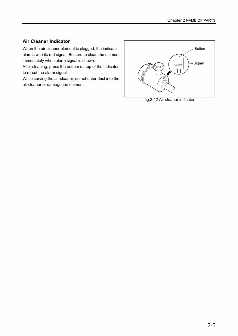
Air Cleaner IndicatorWhen the air cleaner element is clogged, the indicator alarms with its red signal. Be sure to clean the element immediately when alarm signal is shown.After cleaning, press the bottom on top of the indicator to re-set the alarm signal.While serving the air cleaner, do not enter dust into the air cleaner or damage the element.
fig.2-12 Air cleaner indicator
������
�����
2-5

Chapter 2 NAME OF PARTS
Using Turning Gear
Before starting the engine, return (pull out) the turning gear to the original position. Starting the engine with the turning gear pushed in not only damages the ring gear but also may result in personal injury.
1 Loosen the two bolts, and remove the plate from the shaft groove.
2 Push in the shaft fully to engage it with the ring gear.
3 Turn the shaft using a socket wrench and a ratchet handle.
4 After turning, pull out the shaft, insert the plate in the shaft groove, and tighten the bolts.
Make sure the plate is securely inserted in the shaft groove.
fig.2-13 Turning gear position(Engine in operation)
Bolt
Bolt
Shaft
Plate
fig.2-14 Turning gear position(Shaft pushed in)
fig.2-15 Turning gear position(Turning shaft)
Ratchet
Socket
2-6

Chapter 3 OPERATION
Chapter 3 OPERATIONPreparation for Operation of New or Overhauled EngineBefore operating a new or overhauled engine, do the following inspection. For second operation onward, do the following normal operation outlined on page 3-8 "Normal Engine Operation".
Fuel System
When handling fuel, make sure there are no flames near the engine. Wipe any spilled fuel completely. Spilled fuel can ignite and cause fire.
Do not remove the strainer when filling the fuel tank.Use fuel specified in "Fuel" (4-2).
Pouring fuel1 Make sure the insides of the fuel tank and fuel pipes are clean.2 Pour fuel into the fuel tank.3 Remove the fuel feed pipe and drain plug from the fuel inlet of the engine, and check the discharged fuel
for dust particles.4 Reinstall the drain plug and fuel feed pipe.5 Add fuel until the fuel level gage indicates "FULL."
3-1

Chapter 3 OPERATION
Bleed the fuel system
When fuel overflows from the air vent plug, wipe thoroughly with a cloth. Spilled fuel is a fire hazard.After bleeding, lock the priming pump cap securely. If the cap is not locked tightly, the priming pump can be damaged, causing fuel leakage that may lead to a fire. To lock the prim-ing pump cap, follow the procedure described on the following page.
Closing all air vent plugs before locking the priming pump cap disallows the priming pump cap from returning to the original position due to internal pressure.
Bleed air from the location closest to the fuel tank that are the fuel filters, then the fuel injection pump.
Fuel filters1 Loosen the air vent plug on the fuel filter of the
double-filter system by rotating about 1.5 turns.2 Loosen the priming pump cap by turning coun-
terclockwise and move it up and down.3 When there are no air bubbles in the fuel flowing
from the air vent plug, tighten the air vent plug to the specified torque.
4 Repeat the same procedure with the right fuel filter.
5 Repeat the same procedure with the fuel filters located on the other side of the engine.
Fuel injection pump1 Loosen the air vent cock on the fuel injection
pump by rotating about 1.5 turns.2 Move the priming pump cap up and down
repeatedly. When there are no air bubbles in the fuel flowing from the air vent cock, press down the priming pump cap and turn the cap clock-wise.
3 Tighten the air vent cock on the fuel injection pump.
fig.3-1 Using the priming pump
[Unlock ] [Prime] [Lock]
Turn counterclockwise
Move cap up and down
Turn conterclockwise while pressing
fig.3-2 Fuel filters
Air vent plug
Tightening torque7.8 to 9.8 N⋅m�(0.8 to 1.0 kgf⋅m
Air vent plug
fig.3-3 Fuel injection pump
3-2

Chapter 3 OPERATION
Priming pump cap tightening method1 Turn the priming pump cap by hand until the
force required to turn the cap increases sud-denly.
2 With the cap at the position described above, place a mark on the cap.
3 Then, use a wrench or another appropriate tool to tighten the priming pump cap 90±10°.
4 Check the cap to make sure that the head pack-ing is not protruding.
Note: If the head packing is protruding, loosen the priming pump cap, check the packing to make sure it is not damaged, then retighten the priming pump cap.If the head packing is damaged, the priming pump or feed pump must be replaced. Con-tact a Mitsubishi dealer.
If the priming pump cap is not tightened firmly, internal threads can wear quickly due to friction caused by engine vibrations, resulting in sudden ejection of the priming pump cap to cause a fuel spill.On the other hand, if the priming pump cap is tight-ened with excessive force (turned 120° or more), the head of the priming pump can become dam-aged.To prevent such problems, be sure to turn the cap the specified angle (90±10°).
fig.3-4 Priming pump cap tightening method
�������� ������ �������������� �����������
��� ������ ��� ������� ����������������� � ���
������ ���� ���
�� ���
fig.3-5 Priming pump cap packing
���� �����
3-3

Chapter 3 OPERATION
Lubricating SystemPouring engine oil
1 Remove the cap from the oil filler located on the left side of the engine.
2 Pour engine oil of the specified type.
Note: Regarding engine oil, refer to "Engine Oil" (4-4).
3 Check the oil pan and other parts for oil leaks. Repair any oil leakage found.
4 Operate the engine oil priming pump to circulate oil in the engine.
5 Remove the rocker cover, and make sure that oil is supplied to the valve mechanisms.
6 Stop the priming pump. After about 30 minutes, add engine oil until the oil level reaches the Maximum line on the oil level gage.
7 Reinstall the cap on the oil filler.8 The oil level should be between the MAXIMUM
and MINIMUM marks on the oil level gage.If the oil level is low, add engine oil of the speci-fied type.
9 Check the oil pan and other parts for oil leaks.Repair any oil leakage found.10 Crank the engine for about 10 seconds or less using the starters, and wait for about 1 minute.
Repeat the above cranking operation several times to circulate oil throughout the engine.
To crank the engine, shut off the fuel supply to the engine (keep the control rack of the fuel injection pump in the OFF position) and operate the starters.When conducting the above cranking operation, also check the items to be inspected for the cooling system by cranking.
11 Check the oil level with the oil level gage again, and add oil if necessary.
fig.3-6 Oil filler and oil level gage
Oil filler Oil level gage
fig.3-7 Pouring engine oil on valve mechanismsand chamber
Camshaft�oil bath
Specified engine oil:Class CD or CF
Engine oil capacityOil pan: 150 L [39.63 U.S. gal.]
(API Service Classification)
(entire engine: 200 L [52.84 U.S.gal.])
3-4
Chapter 3 OPERATION
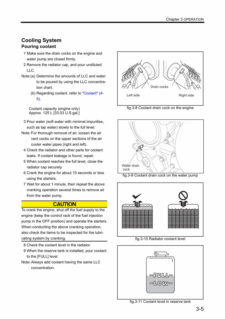
Cooling SystemPouring coolant
1 Make sure the drain cocks on the engine and water pump are closed firmly.
2 Remove the radiator cap, and pour undiluted LLC.
Note:(a) Determine the amounts of LLC and water to be poured by using the LLC concentra-tion chart.
(b) Regarding coolant, refer to "Coolant" (4-5).
3 Pour water (soft water with minimal impurities, such as tap water) slowly to the full level.
Note: For thorough removal of air, loosen the air vent cocks on the upper sections of the air cooler water pipes (right and left).
4 Check the radiator and other parts for coolant leaks. If coolant leakage is found, repair.
5 When coolant reaches the full level, close the radiator cap securely.
6 Crank the engine for about 10 seconds or less using the starters.
7 Wait for about 1 minute, then repeat the above cranking operation several times to remove air from the water pump.
To crank the engine, shut off the fuel supply to the engine (keep the control rack of the fuel injection pump in the OFF position) and operate the starters.When conducting the above cranking operation, also check the items to be inspected for the lubri-cating system by cranking.
8 Check the coolant level in the radiator.9 When the reserve tank is installed, pour coolant
to the [FULL] level.Note: Always add coolant having the same LLC
concentration.
fig.3-8 Coolant drain cock on the engine
����� ����
�� ��� ���� ���
fig.3-9 Coolant drain cock on the water pump
Water drain cock
fig.3-10 Radiator coolant level
fig.3-11 Coolant level in reserve tank
Coolant capacity (engine only)Approx. 125 L [33.03 U.S.gal.]
3-5
Chapter 3 OPERATION
Checking Battery
If electrolyte is spilled on the eyes, skin or clothes, wash immediately with plenty of water. If electrolyte enters the eyes, flush immediately with lots of fresh water and see a physician.Do not use flames near the battery. When handling the battery, be careful of sparks generated by accidental shorting.Regarding other cautions in handling the battery, refer to "Caution Service Battery" (1-5).
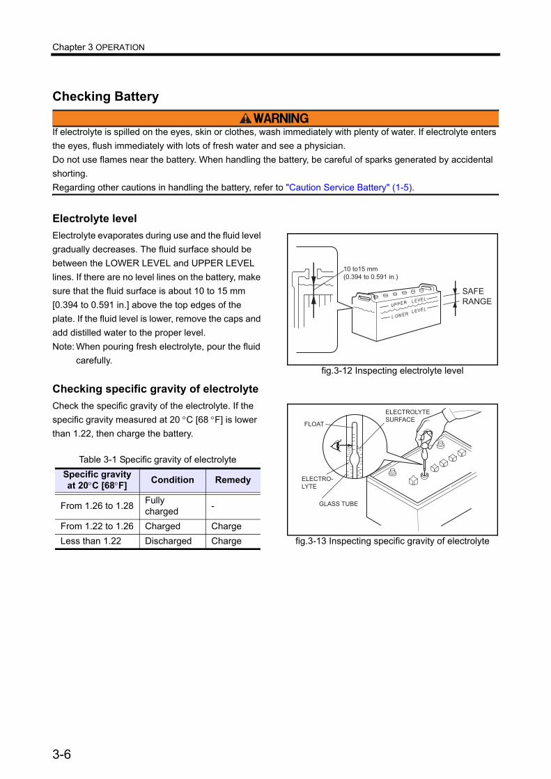
Electrolyte levelElectrolyte evaporates during use and the fluid level gradually decreases. The fluid surface should be between the LOWER LEVEL and UPPER LEVEL lines. If there are no level lines on the battery, make sure that the fluid surface is about 10 to 15 mm [0.394 to 0.591 in.] above the top edges of the plate. If the fluid level is lower, remove the caps and add distilled water to the proper level.Note: When pouring fresh electrolyte, pour the fluid
carefully.
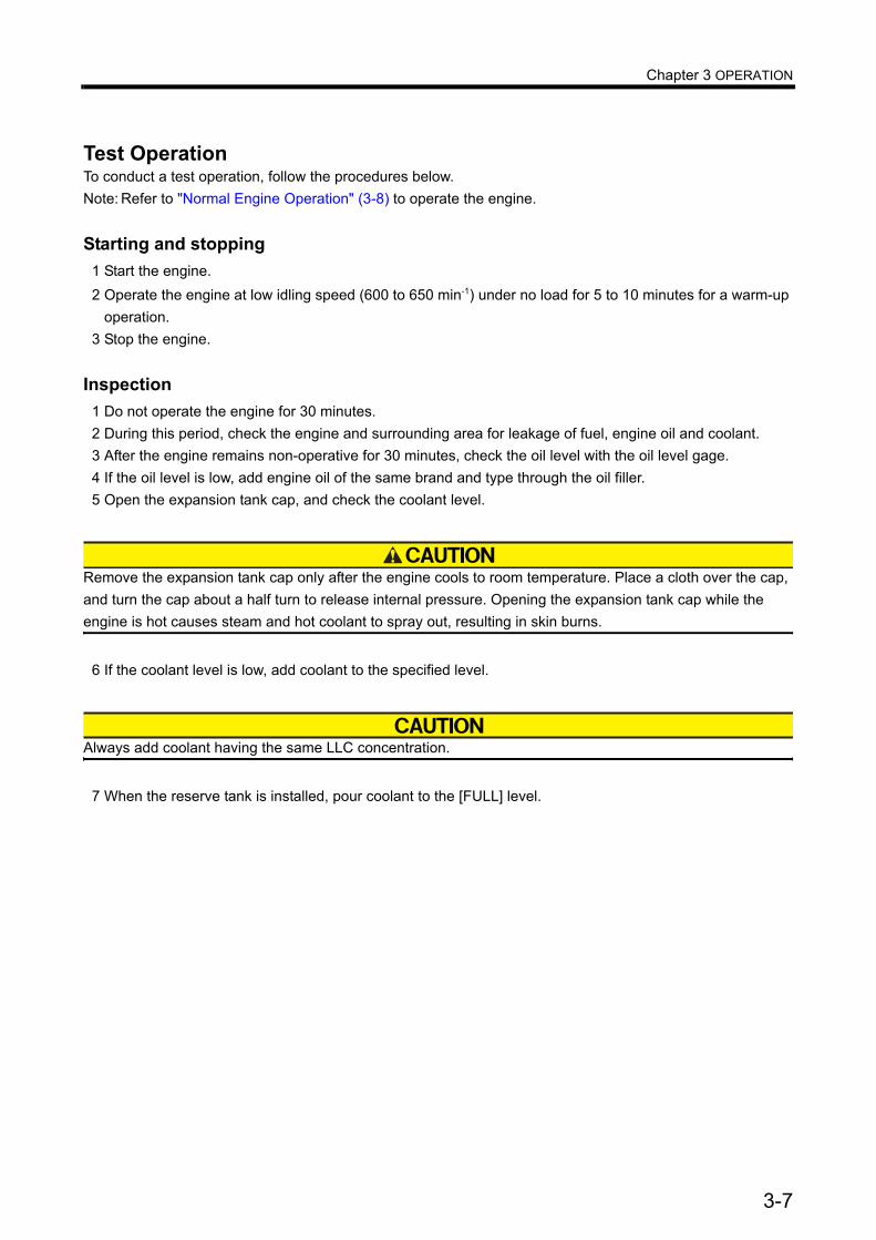
Checking specific gravity of electrolyte Check the specific gravity of the electrolyte. If the specific gravity measured at 20 °C [68 °F] is lower than 1.22, then charge the battery.
Table 3-1 Specific gravity of electrolyteSpecific gravity at 20°C [68°F] Condition Remedy
From 1.26 to 1.28 Fully charged -
From 1.22 to 1.26 Charged ChargeLess than 1.22 Discharged Charge
fig.3-12 Inspecting electrolyte level
�����
� ����
�����
�����
� ��� ��
����� �� � �� ����
����
�����
fig.3-13 Inspecting specific gravity of electrolyte
�����
�����������
�����
��������
����
��� ���
3-6
Chapter 3 OPERATION
Test OperationTo conduct a test operation, follow the procedures below.Note: Refer to "Normal Engine Operation" (3-8) to operate the engine.
Starting and stopping1 Start the engine.2 Operate the engine at low idling speed (600 to 650 min-1) under no load for 5 to 10 minutes for a warm-up
operation.3 Stop the engine.
Inspection1 Do not operate the engine for 30 minutes.2 During this period, check the engine and surrounding area for leakage of fuel, engine oil and coolant.3 After the engine remains non-operative for 30 minutes, check the oil level with the oil level gage.4 If the oil level is low, add engine oil of the same brand and type through the oil filler.5 Open the expansion tank cap, and check the coolant level.
Remove the expansion tank cap only after the engine cools to room temperature. Place a cloth over the cap, and turn the cap about a half turn to release internal pressure. Opening the expansion tank cap while the engine is hot causes steam and hot coolant to spray out, resulting in skin burns.
6 If the coolant level is low, add coolant to the specified level.
Always add coolant having the same LLC concentration.
7 When the reserve tank is installed, pour coolant to the [FULL] level.
3-7
Chapter 3 OPERATION
Normal Engine OperationThe following describes the procedures for operating the engine in normal operating condition.
Should an engine abnormality be observed during operation, stop the engine and correct the problem, or con-tact a Mitsubishi dealer.
Preparations for Operation (Pre-Start Inspection)Always conduct the following inspection before starting the engine.
External Inspection
A fire can be caused by combustible materials placed near hot engine parts (exhaust manifolds and other exhaust gas passages) or battery, fuel leaks, and oil leaks. Check the engine exterior carefully. If an abnor-mality is found, be sure to repair or contact a Mitsubishi dealer.Before starting the engine, clean the top surface of the battery with wet cloth.
Inspect the engine exterior as described below.
1 Make sure there is no combustible material near the engine or battery. Also, check to make sure the engine and battery are clean.If combustible materials or waste are found near the engine or battery, remove them.
2 Check the entire engine for leakage of fuel, engine oil coolant. If leaks are found, repair leakage or contact a Mitsubishi dealer.
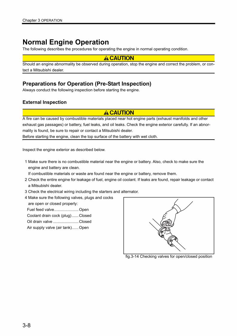
3 Check the electrical wiring including the starters and alternator.4 Make sure the following valves, plugs and cocks
are open or closed properly:Fuel feed valve......................OpenCoolant drain cock (plug) ......ClosedOil drain valve .......................ClosedAir supply valve (air tank)......Open
fig.3-14 Checking valves for open/closed position
3-8
Chapter 3 OPERATION
Draining Water from Fuel Tank
When handling fuel, make sure there are no flames or heat source in the area.Wipe any spilled fuel completely. Spilled fuel can ignite and cause fire.
Do not remove the strainer when filling the fuel tank.Use fuel specified in "Fuel" (4-2).
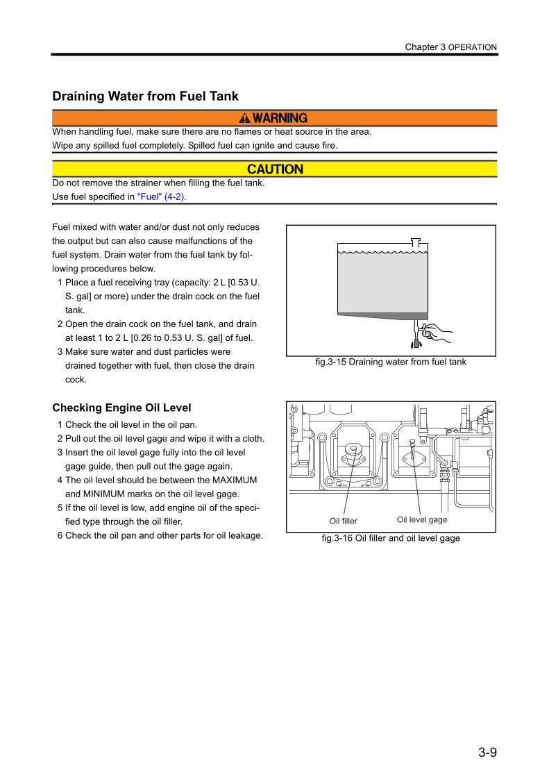
Fuel mixed with water and/or dust not only reduces the output but can also cause malfunctions of the fuel system. Drain water from the fuel tank by fol-lowing procedures below.
1 Place a fuel receiving tray (capacity: 2 L [0.53 U. S. gal] or more) under the drain cock on the fuel tank.
2 Open the drain cock on the fuel tank, and drain at least 1 to 2 L [0.26 to 0.53 U. S. gal] of fuel.
3 Make sure water and dust particles were drained together with fuel, then close the drain cock.
Checking Engine Oil Level
1 Check the oil level in the oil pan.2 Pull out the oil level gage and wipe it with a cloth.3 Insert the oil level gage fully into the oil level
gage guide, then pull out the gage again.4 The oil level should be between the MAXIMUM
and MINIMUM marks on the oil level gage.5 If the oil level is low, add engine oil of the speci-
fied type through the oil filler.6 Check the oil pan and other parts for oil leakage.
fig.3-15 Draining water from fuel tank
fig.3-16 Oil filler and oil level gage
Oil filler Oil level gage
3-9

Chapter 3 OPERATION
Checking Coolant Level
Remove the radiator cap only after the engine cools to room temperature. Place a cloth over the cap, and turn the cap about a half turn or stand the lever to upright position to release internal pressure. Opening the radiator cap while the engine is hot causes steam and hot coolant to spray out, resulting in skin burns.
1 Open the radiator cap and check the coolant level.
2 If the coolant level is low, add coolant to the specified level.
Always add coolant having the same LLC concen-tration.
Note:(a) Determine the amounts of LLC and water to be poured by using the LLC concentra-tion chart.
(b) Regarding coolant, refer to "Coolant" (4-5).3 If the reserve tank is installed, pour coolant to the
reserve tank up to the [FULL] line.
Inspection of the air cleaner indicator1 Check the air cleaner indicator for the element
clog.2 If the element clogs, the red signal mark is visi-
ble.3 Immediately clean the air cleaner element when
the signal turns red.Note: Regarding cleaning of the air cleaner element,
refer to "Cleaning and Inspecting Air Cleaner Element" (6-12).
fig.3-17 Radiator cap
���� ��� ��� �
�� � � ���
���� �� ����
������ �����
fig.3-18 Radiator coolant level
fig.3-19 Reserve tank coolant level
fig.3-20 Air cleaner indicator
������
�����
3-10

Chapter 3 OPERATION
Inspection of Air Tank Air PressureCheck the air pressure gage to see if the air pres-sure in the air tank conforms to the standard.Air tank internal pressure standard: 2.94 MPa (30 kgf/cm2) [426 psi]
fig.3-21 Inspection of air tank air pressure
Air pressure gages
3-11
Chapter 3 OPERATION
StartingThe starting method varies depending on the appli-cation and specifications. Start the engine accord-ing to the specified procedure.
Before starting the engine, check to make sure no one is near the engine and tools are not left on or near the engine. In loud voice, notify peo-ple in the area when starting the engine.
Never load the engine at starting time. (Disengage the clutch if it is installed.)
Warming-up Operation
Do not approach rotating parts while in opera-tion.Entanglement by rotating parts can cause seri-ous injury.
Do not conduct warm-up operation for an extended period of time.Prolonged warm-up operation causes carbon buildup in the cylinders that leads to incomplete combustion.Do not turn the battery switch to OFF. Turning the battery switch to OFF while the engine is in warm-up operation causes malfunctioning of instruments and deteriorates the diodes and transistors in the alternator.Never turn the key to START position. If so, starter may be damaged.During warming-up operation, do not load the engine if exhaust smoke is black. Overloading the engine (indicated by black smoke) not only causes high fuel consumption but also excessive carbon deposits inside the engine, thus it can reduce the service life of the engine.
After the engine starts, operate at no load min. rated speed speed for 5 to 10 minutes to warm up.
During warming-up operationDuring warming-up operation, check if the oil pres-sure is in the range of standard value.Also, make sure the oil pressure gage is operating properly.Note: The oil pressure gage indicates higher pres-
sure than normal immediately after the engine starts since the oil temperature is low. This does not denote an abnormality. The pressure gradually lowers to the normal level as the oil temperature rises.
External inspection during warming-upCheck the external view of the engine to make sure there is no fuel, oil, cooling water or exhaust gas leakage from joints.
3-12
Chapter 3 OPERATION
Operation
Do not approach rotating parts while in opera-tion. Entanglement by rotating parts can cause serious injury.
Do not touch any part of the engine while it is oper-ating or immediately after it is shut down. A hot engine can cause burns.
Provide adequate ventilation in the engine room. If air supplied to the engine room is restricted, the room temperature increases and can affect engine output and performance.During the first 50 hours of operation, break-in the engine by operating it with light load and at lower speed than normal.Operating the engine under high load or severe conditions during the break-in period can shorten the service life of the engine.Do not turn the battery switch to OFF when the engine is in operation. Turning the battery switch to OFF while the engine is in operation not only stops the battery charge but also causes malfunctioning of instruments and deteriorates the diodes and transistors in the alternator.Never turn the key to the START position while the engine is operating. The starter may be damaged.
After the warm-up operation, start operating the engine with load.
Inspection during operationCheck for leakages.Inspect the exterior of the engine to make sure there is no leakage from joints.Check to make sure the engine does not produce abnormal noise or vibrations.Inspect the engine for abnormal operating sound and vibrations such as knocking.Check to make sure the exhaust gas is normal color.Check the color of the exhaust gas discharged from the exhaust pipe.Note: Regarding abnormal exhaust gas conditions,
refer to "Other Problems and Countermea-sures" (9-3).
Check to make sure the instruments and gages indicate normal values.
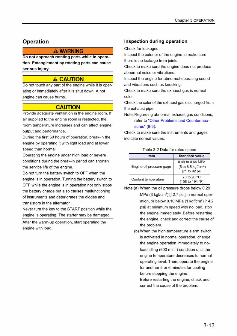
Note:(a) When the oil pressure drops below 0.29 MPa (3 kgf/cm2) [42.7 psi] in normal oper-ation, or below 0.10 MPa (1 kgf/cm2) [14.2 psi] at minimum speed with no load, stop the engine immediately. Before restarting the engine, check and correct the cause of the problem.
(b) When the high temperature alarm switch is activated in normal operation, change the engine operation immediately to no-load idling (600 min-1) condition until the engine temperature decreases to normal operating level. Then, operate the engine for another 5 or 6 minutes for cooling before stopping the engine.Before restarting the engine, check and correct the cause of the problem.
Table 3-2 Data for rated speedItem Standard value
Engine oil pressure gage0.49 to 0.64 MPa (5 to 6.5 kgf/cm2)
[71 to 92 psi]
Coolant temperature 70 to 90 °C [158 to 194 °F]
3-13

Chapter 3 OPERATION
Stopping
Stopping the engine abruptly while engine parts are hot due to high-speed operation can be a cause for heat up of the engine parts and shorten the service life of the engine. Before stopping the engine, let it operate at low idle speed for 5 to 6 minutes to cool down operation. Stopping the engine immediately after high-speed operation can cause engine parts to be heated up and result in bad effects.During cooling operation, check the engine for abnormalities.Do not accelerate the engine prior to shutting it down.Do not restart the engine immediately after it shuts down due to an abnormality. If an alarm is generated when the engine stops, locate the cause of the problem and correct the problem before restarting the engine.Continuing engine operation without correcting the problem can result in a serious accident.
For stopping the engine, follow the instructions since stopping procedure varies depending upon the models and its installed equipment. Emergency Stop
When stopping the engine by pulling the speed con-trol lever, continue pulling the lever until the engine stops completely. If not, the engine may start again
To stop the engine with emergency lever, pull the manual lever to the arrow direction and continue pulling the lever until the engine stops completely.
Inspection After StoppingInspect the engine parts to make sure there is no fuel, oil or coolant leakage. If a fuel or oil leak is found, repair the leakage or contact a Mitsubishi dealer.
fig.3-22 Manual stop lever
STOP
3-14
Chapter 4 MAINTENANCECautions Concerning MaintenanceStop the engine before checking or adding fuel, oil or coolant.
Be sure to stop the engine before checking and adding fuel, engine oil or coolant.Make sure the coolant temperature is suffi-ciently low before checking coolant. Do not check coolant immediately after the engine stops.Do not attempt to adjust the parts while the engine is operating.Failure to follow the above directions may cause fire, skins burns or entanglement by rotating parts.
Handle electrolyte carefully.
Should electrolyte enter eyes or contact the skin or clothes, flush immediately with plenty of water.Should electrolyte enter eyes, wash immediately with water and seek medical attention.
Handle LLC carefully.
Should LLC be accidentally swallowed, induce vomiting immediately and seek medical attention.Should LLC enter eyes, flush immediately with plenty of water and seek medical attention.LLC is a potent alkaline solution. Do not drink or allow it to enter your eyes.
Always wear protective gear.
Wear protective gear such as a hardhat, face shield, work clothes, safety shoes, dust protective mask, etc.Be sure to wear protective goggles and other pro-tective devices when handling compressed air. Compressed air can cause personal injury if han-dled carelessly.
Use recommended fuel, engine oil and coolant.
Use fuel, engine oil and coolant specified in this manual, and handle them with utmost caution.When adding engine oil, use oil of the same brand. Do not mix oils of different brands.
Perform all specified pre-start inspec-tions and periodic inspections.
Conduct the pre-start inspection and periodic inspection as specified in this manual.Failure to conduct pre-start inspections and peri-odic inspections may cause various engine prob-lems and damage to parts as well as serious accidents.
Use only genuine Mitsubishi parts.
When replacing new parts, use only genuine Mit-subishi parts.To obtain new parts, contact a Mitsubishi dealer.
4-1
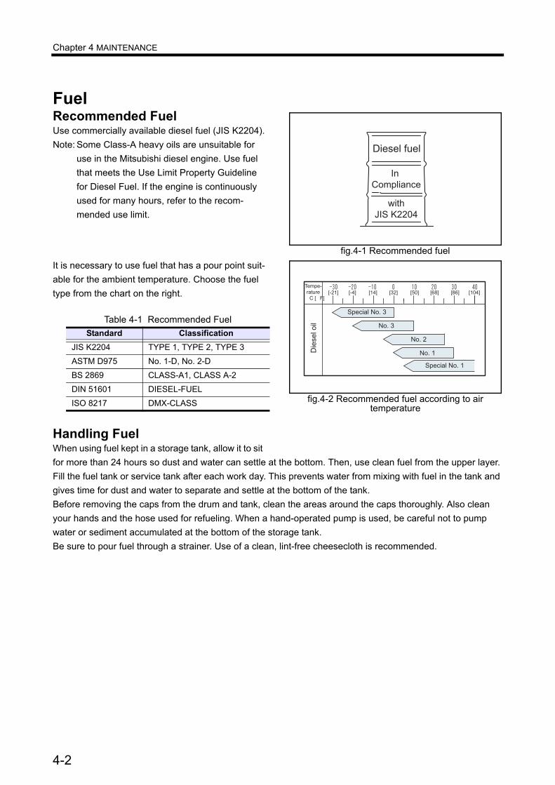
Chapter 4 MAINTENANCE
FuelRecommended FuelUse commercially available diesel fuel (JIS K2204).Note: Some Class-A heavy oils are unsuitable for
use in the Mitsubishi diesel engine. Use fuel that meets the Use Limit Property Guideline for Diesel Fuel. If the engine is continuously used for many hours, refer to the recom-mended use limit.
It is necessary to use fuel that has a pour point suit-able for the ambient temperature. Choose the fuel type from the chart on the right.
Handling FuelWhen using fuel kept in a storage tank, allow it to sit for more than 24 hours so dust and water can settle at the bottom. Then, use clean fuel from the upper layer.Fill the fuel tank or service tank after each work day. This prevents water from mixing with fuel in the tank and gives time for dust and water to separate and settle at the bottom of the tank.Before removing the caps from the drum and tank, clean the areas around the caps thoroughly. Also clean your hands and the hose used for refueling. When a hand-operated pump is used, be careful not to pump water or sediment accumulated at the bottom of the storage tank.Be sure to pour fuel through a strainer. Use of a clean, lint-free cheesecloth is recommended.
Table 4-1 Recommended FuelStandard Classification
JIS K2204 TYPE 1, TYPE 2, TYPE 3
ASTM D975 No. 1-D, No. 2-D
BS 2869 CLASS-A1, CLASS A-2
DIN 51601 DIESEL-FUEL
ISO 8217 DMX-CLASS
fig.4-1 Recommended fuel
Diesel fuel
In �Compliance
with�JIS K2204
fig.4-2 Recommended fuel according to air temperature
Tempe-�rature��C [�F]
[-21]� [-4]� [14]� [32]� [50]� [68]� [86]� [104]
Special No. 3
No. 3
No. 2
No. 1
Special No. 1
Die
sel o
il
4-2

Chapter 4 MAINTENANCE
Table 4-2 Fuel Use Limit Property GuidelineProperty Recommend use limit Current use limit Remarks
Flash point As stipulated by regulation
JIS K2204, 2205Diesel fuel: 50°C or higherClass-A heavy oil: 60 °C [140 °F] or higher
Distillation
First distillation point 170 °C [338 °F] or higher 170 °C [338 °F] or
higherJIS K2254
90% distillation point
330 to 380 °C[626 to 716 °F]
330 to 380 °C [626 to 716 °F]
Pour point More than 6°C [10.8 °F] below ambient tempera-ture JIS K2269
Cloud point Below ambient temperature
Carbon residue (10% residual oil) 0.4 weight % or lower 1.0 weight % or lower JIS K2270
Cetane number 45 or higher
Cetane index (new) 45 or higher JIS K2280-1996
Kinetic viscosity
2.0 mm2/s [0.0031 in2] or higher (30 °C [86 °F])8.0 mm2/s [0.0124 in2] or lower (50 °C [122 °F])10.5 mm2/s [0.0163 in2] or lower (40 °C [104 °F])16.0 mm2/s [0.0248 in2] or lower (30 °C [86 °F])
Sulfur content 0.2 weight % or lower 1.0 weight % or lowerJISK25410.05 weight % (same as diesel fuel) is rec-ommended.
Water and sediment 0.1 volume % or lower JIS K2275
Ash 0.03 weight % or lower JIS K2272
Copper plate corrosion (100°C [212°F], 3 hrs.) No.3 or lower No.3 or lower
ASTM - No.3JIS K2513 - Discoloration No.3
Specific gravity (15°C [59°F]) 0.83 to 0.87 0.80 to 0.87
Coking test
Should not be carbonized more than 75% at 250 °C [482 °F]
Should not be carbon-ized 100% at 250 °C [482 °F]
Fed791B (U.S.)250 °C [482 °F] X 24Hr230 °C [446 °F] X 24Hr180 °C [356 °F] X 48Hr
Should not be evapo-rated more than 55% at 230 °C [446 °F]
Should not be turn to tar at 180 °C [356 °F]
Aromatics content(HPLC method) 38 weight % or lower 38 weight % or lower JIS K 2536
Total of aromatic content
Asphaltene 0.1 weight % or lower 0.1 weight % or lower ICP analysis (U.K.)
Particulate contaminant 5.0 mg/l or lower 5.0 mg/l or lowerJIS B9931Including foreign substance in the fuel pipe lines
4-3
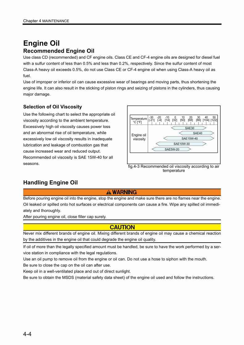
Chapter 4 MAINTENANCE
Engine OilRecommended Engine OilUse class CD (recommended) and CF engine oils. Class CE and CF-4 engine oils are designed for diesel fuel with a sulfur content of less than 0.5% and less than 0.2%, respectively. Since the sulfur content of most Class-A heavy oil exceeds 0.5%, do not use Class CE or CF-4 engine oil when using Class-A heavy oil as fuel.Use of improper or inferior oil can cause excessive wear of bearings and moving parts, thus shortening the engine life. It can also result in the sticking of piston rings and seizing of pistons in the cylinders, thus causing major damage.
Selection of Oil ViscosityUse the following chart to select the appropriate oil viscosity according to the ambient temperature.Excessively high oil viscosity causes power loss and an abnormal rise of oil temperature, while excessively low oil viscosity results in inadequate lubrication and leakage of combustion gas that cause increased wear and reduced output.Recommended oil viscosity is SAE 15W-40 for all seasons.
Handling Engine Oil
Before pouring engine oil into the engine, stop the engine and make sure there are no flames near the engine.Oil leaked or spilled onto hot surfaces or electrical components can cause a fire. Wipe any spilled oil immedi-ately and thoroughly.After pouring engine oil, close filler cap surely.
Never mix different brands of engine oil. Mixing different brands of engine oil may cause a chemical reactionby the additives in the engine oil that could degrade the engine oil quality.
If oil of more than the legally specified amount must be handled, be sure to have the work performed by a ser-vice station in compliance with the legal regulations.Use an oil pump to remove oil from the engine or oil can. Do not use a hose to siphon with the mouth.Be sure to close the cap on the oil can after use.Keep oil in a well-ventilated place and out of direct sunlight.Be sure to obtain the MSDS (material safety data sheet) of the engine oil used and follow the instructions.
fig.4-3 Recommended oil viscosity according to air temperature
��� ��� ��� �� �� �� �� ���
����
����
�������
�������
������
�� ����������� ����
����� ��� ��� !� ��"
�����# ����# ����#����# ����# �$%�# �%$�#�����#�����
4-4

Chapter 4 MAINTENANCE
Coolant
Recommended CoolantWater used in the engine cooling system must be soft water. The water quality must meet the following requirements.Water quality should meet with recommended limit, however, within limit is acceptable.
Note: Figures in parentheses are the standard value. In addition to the items specified above, turbidity is spec-ified to be below 15 mg/liter.
Long Life Coolant (LLC)
Should LLC be accidentally swallowed, induce vomiting immediately and seek medical attention.If LLC should enter eyes, flush immediately with plenty of water and seek medical attention.
Be sure to use long life coolant (LLC) as coolant, because it prevents not only freezing of coolant but also rusting of the cooling system.Use an all-season, non-amine type LLC.
Table 4-3 Water quality standards
Item Chemical symbol Unit Recommended Limit
Main adverse effectCorrosion and rust
Scale formation
pH (25°C [77°F]) - - 6.5 to 8.5 6.5 to 8.5 O OElectrical conductiv-ity (25°C [77°F]) - /cm <250 <400 O O
Total hardness CaCO3 ppm < 95 < 100 - OM alkalinity CaCO3 ppm < 70 < 150 - OChlorine ion Cl ppm < 100 < 100 O -
Sulfuric acid ion SO2 4- ppm < 50 < 100 O -
Total iron Fe ppm < 1.0 < 1.0 - OSilica SiO2 ppm - < 50 - OResidue from evap-oration - ppm < 250 < 400 - O
µ
4-5

Chapter 4 MAINTENANCE
Recommended LLCRecommended brands of LLC are shown in the chart below.
Note: When using an LLC other than the above, fre-quent inspections are required since the ser-vice life may be shorter.
Features and Performance of Rec-ommended LLC• Use LLC with no amine content.• Use LLC with no silicate or borate.• Use LLC that is close to neutral on the pH scale
and slightly alkaline.• Use LLC that contains balanced chemical addi-
tives as substitutes for amines.• Use LLC that offers long life (with 30% LLC con-
centration and service life of more than 1 year).
Maintenance of LLC
Coolant (containing LLC) drained from an engine is toxic, and must not be disposed of into regular sew-age. For disposal of used coolant, consult a Mitsubishi dealer.
Replacement timing of LLCWhen a coolant mixed with the LLC recommended by our company is used, replace coolamt every 12000 hours or 2 years, whichever comes first, in a regular-use or general-purpose engine. In an emer-gency engine, replace coolant every 2 years.
LLC concentrationWhen determining the LLC concentration, provide a margin of 5°C [41°F] below the expected lowest temperature in your region. Maintain the LLC con-centration between 30 and 60% throughout the year.LLC of less than 30% concentration does not pro-vide sufficient corrosion protection. If the LLC con-centration is as low as several percent, it may promote corrosion.LLC of more than 60% concentration can adversely affect its freeze protection characteristic and cause the engine to overheat easily. When adding coolant without changing all coolant, do not add plain water. Always use coolant having the same LLC concentration.
Note: For determining the accurate LLC concentra-tion, refer to the instructions for the LLC used.
Table 4-4 Recommended brands of LLCManufacturer Brand
Nippon Oil Corporation Super Coolant X
Mitsubishi Fuso Truck & Bus Corporation
Fuso Diesel Long Life Coolant
TEXACO Code 7998
Table 4-5 Recommended LLC concentration (for reference only)
Lowest ambient temperature
(°C [°F])
up to -15 [5]
up to -24
[-11]
up to -36
[-32]
up to -43
[-45]LLC concentra-tion (%) 30 40 50 55
4-6

Chapter 4 MAINTENANCE
Importance of LLCToday's trend is toward smaller and more light-weight engines offering greater output, lower fuel consumption and lower exhaust emission level.Conditions to which engine coolant is subjected are becoming severer due to longer operating hours, higher coolant temperature and higher coolant cir-culating speed.Many different materials (such as steel, aluminum, copper, solder and rubber) are used in the cooling system, and they are also subjected to the severe conditions described above.These materials differ in ionizing tendency, and this difference promotes corrosion through the medium of engine coolant.To prevent the above problem, it is necessary to use LLC (long life coolant).
Characteristics of LLC Additive and Important NotesLLC contains several chemicals in such proportions as to produce chemical reactions that suppress corrosion (ionization) of engine parts in contact with the coolant.LLC loses its effectiveness after many months of use.Moreover, if the chemicals are not well propor-tioned to match the metals used in the cooling sys-tem, certain chemicals in the LLC become rapidly used up and result in dissolving of metals.Moreover, other corrosion preventing chemicals react with dissolving metals and further accelerate corrosion. This condition can result in more corro-sion than when plain soft water is used. This prob-lem is often caused by the use of inappropriate LLC.
Examples of Abnormalities Caused by LLC
Pitting on iron partsAmines are generally effective in suppressing the rusting of ferrous metals, but they are said to cause problems for copper parts.Dissolved copper (copper corrosion) in the cooling system deposits on iron parts, and copper deposits produce galvanic or local-cell action, thus corroding and pitting iron that has a higher ionizing tendency.
Corrosion of aluminum partsSilicate is highly effective in protecting aluminum against rusting. However, it is unstable in a solution in which pH is 9 or lower, and can turn to gel and precipitate in the solution. For this reason, the pH is usually specified to be about 10 to ensure a high alkaline level.This means, after silicate is used up, the high alka-linity causes chemical attacks on aluminum. To pre-vent this problem, proper maintenance of the coolant is required.(Example)Rapid wear of mechanical seals in the water pump due to secondary effects of silicate gel formed.Corrosion of aluminum parts after silicate is con-sumed.
Pitting and clogging of radiatorAs LLC's general performance deteriorates or when its concentration in the coolant is too low, its anti-corrosion performance lowers and results in the corrosion of metals.Brass and solder tend to corrode faster than other metals, and corrosion of these metals is said to cause water leakage and clogs.(Example)Holes and clogs in radiator
4-7
Chapter 4 MAINTENANCE
FiltersFilters remove impurities such as dust particles from fuel, engine oil and air starter system. While it is important to use clean fuel, engine oil and air supply, filters must be changed regularly to ensure maximum engine performance and extend the ser-vice life of the engine.Refer to "Periodic Maintenance Chart" (5-1) for the procedure for changing filters. The interval of changing filters can be shortened depending on the usage and operating conditions as well as quality of fuel and oil in use.When replacing filters, use genuine Mitsubishi parts.Do not wash and reuse cartridge-type filters.Always use new filters.When filters are changed, inspect the removed fil-ters for metal particles. If metal particles are found, consult a Mitsubishi dealer.
Electrical PartsDo not splash water on electrical parts. Water can cause electrical leakage and short-circuiting, result-ing in equipment damage. Wet electrical parts can also cause electric shock.When cleaning the engine, keep water away from electrical parts. If malfunctioning of electrical parts is suspected, consult a Mitsubishi dealer.Also, do not use disassembled or reassembled electrical parts.
4-8

Chapter 4 MAINTENANCE
Cautions in Operating Engine in Cold Weather SeasonWhen the ambient temperature is low, fuel and engine oil become thick and coolant can freeze, thus making it difficult to start the engine or causing damage to the cylinder heads. To prevent these problems, observe the following directions.
Fuel
When handling fuel, make sure there are no flames near engine.Wipe any spilled fuel completely. Spilled fuel can ignite and cause fire.
Use appropriate fuel according to the ambient tem-perature.Note: Regarding fuel, refer to "Fuel" (4-2).
Engine OilReplace engine oil suitable to the ambient tempera-ture.Note: Regarding engine oil, refer to "Engine Oil" (4-
4).
Coolant
Remove the radiator cap only after the engine cools to room temperature. Place a cloth over the cap, and turn the cap about a half turn to release pres-sure. Opening the radiator cap while the engine is hot causes steam and hot coolant to blow out, resulting in skin burns.
Freezing of coolant due to cold temperatures can damage the crankcase. Be sure to use all-season long life coolant that prevent freezing of cooling water and rusting of the engine cooling system.Note: Regarding coolant, refer to "Coolant" (4-5).
Battery
Never use flames near the battery, and be care-ful to handle battery since flames can cause an explosion.
If electrolyte is spilled on skin or clothes, wash immediately with lots of water. If electrolyte gets into your eyes, flush immediately with lots of fresh water and consult a physician as soon as possible.For other cautions to handle battery, refer to "Cau-tion Service Battery" (1-5)
When the ambient temperature drops to a very low level, the charging rate becomes low even if the specific gravity of electrolyte remains the same. Therefore, in a cold area the battery may not pro-vide sufficient power to start the engine immedi-ately. Furthermore, electrolyte becomes easier to freeze when its specific gravity is low. Therefore, it is recommended to additionally charge the battery to increase the specific gravity of electrolyte and the charging rate.Note: For the inspection of specific gravity of elec-
trolyte, refer to "Checking specific gravity of electrolyte" (3-6).
Maintenance After Cold SeasonAfter a cold season ends, change fuel, engine oil and coolant to those suitable for the outside tem-perature in accordance with the specifications described in this manual.
4-9

Chapter 5 PERIODIC MAINTENANCE CHARTHow to Use Periodic Maintenance ChartPeriodic inspection not only extends the service life of the engine but also serves to ensure safe opera-tion. Be sure to conduct inspections and mainte-nance according to the periodic maintenance chart.The maintenance chart shows the standard service intervals. Whenever you notice the abnormalities mentioned below, make sure the service must be performed to the defective part of the engine, regardless recommended service intervals in the “Periodic Maintenence Chart”; abnormal noise, black exhaust smoke, white exhaust smoke, abnor-mally high temperature of exhaust gas, abnormal vibration in engine, fuel, oil or exhaust gas leakage.Note: Appropriate service intervals vary depending
on the usage and operating conditions as well as consumption of fuel, oil and coolant. Check the operating record of the engine to determine the most appropriate service inter-vals. (Feel free to consult a Mitsubishi dealer regarding service intervals.)
Perform service items listed under the service inter-val. Service items with shorter intervals should also be included in the longer interval service.Items marked with ¤ in the maintenance chart require special tools or large equipment. For the servicing of these items, consult a Mitsubishi dealer.
Periodic Maintenance ChartAppropriate service intervals vary depending on the engine specifications. Perform all daily inspection and maintenance items in an accordance with the following 3 categories.
Periodic maintenance chart for regular-use engineWhen the engine is used as a regular use engine, perform the periodic inspection and maintenance in accordance with the "Periodic Maintenance Chart for Engine in Regular Use".
Periodic maintenance chart for emer-gency engineWhen the engine is used as an emergency engine, perform the periodic inspection and maintenance in accordance with the "Periodic Maintenance Chart for Emergency Engine".Due to the nature of application, an emergency engine is subject to demanding operating condi-tions such as a quick startup and immediate supply of power. In addition, it must operate reliably in the event of an emergency. Therefore, be sure to per-form the daily inspection and also conduct the fol-lowing operation for maintenance purposes.
Once every week: Operate the engine under no load (for 3 to 5 minutes).(When operating the engine for the adjustment of peripheral devices, limit the operating time to 10 minutes.)Once every month: Operate the engine under load (for 15 to 30 minutes with more than 1/2 load).If the engine cannot be operated under load every month, operate the engine under load (more than 1/2 load) for more than 2 hours.During the engine maintenance operation, check the ease of startup, oil pressure, and exhaust color and vibration.
Periodic maintenance chart for general-purpose engineIf the engine is used for different purposes other than the above usage, do maintenance according to the “Periodic Maintenance Chart for General-Purpose Power Supply Engine”.
5-1
Chapter 5 PERIODIC MAINTENANCE CHART
General Definition of Regular-Use Engine, Emergency Engine and General-Purpose Engine
General definition of regular-use engineAn engine operated with a constant base load for the purpose of generating electric power, which is used independently or in combination with commer-cial power supply.An engine operated under a fluctuating load throughout a day for supplying rated electric power in lieu of commercial power.
General definition of emergency engineAn engine used for emergency power generation such as main power supply and commercial power supply.
General definition of general-purpose engineAn engine used for a purpose other than power generation - for example, to drive a pump, as the main engine for a ship, and for an industrial vehicle - and operated under constant or cylically varying load and speed.
5-2

Chapter 5 PERIODIC MAINTENANCE CHART
Periodic Maintenance Chart for Engine in Regular UseTable 5-1 Periodic Maintenance Chart for Engine in Regular Use (1 / 2)
Service item PageEvery 50 ser-vice hours or every month
Draining Water from the Fuel Tank ∗
First 50 service hours for new or reconditioned engine
Retightening the Bolts and Nuts ∗
Changing Engine Oil, Oil Filters and Bypass Oil Filter(It is recommenced to analyze the engine oil properties at the same time.)(The oil filters must be changed when the filter alarm lights.)
6-6
Every 250 ser-vice hours or every year
Changing Engine Oil, Oil Filters and Bypass Oil Filter (It is recommenced to analyze the engine oil properties at the same time.)(The oil filters must be changed when the filter alarm lights.)
6-6
Changing Governor Oil Filter 6-8First 250 ser-vice hours for new or recondi-tioned engine
Inspection and Adjustment of Valve Clearances(Also inspect the valve mechanisms at the same time.) ∗
Every 1000 ser-vice hours
Inspection of V-belt and Adjustment of Belt Tension 6-2Changing Fuel Filters 6-5
Every 2000 ser-vice hours
Changing V-belt 6-2Inspection of Fuel Control Linkage Ball Joints 6-4Inspection and Adjustment of Valve Clearances(Also check the valve mechanisms at the same time.) ∗
Inspection and Adjustment of Fuel Injection Timing ∗
Changing Fuel Injection Nozzle Tips (Check the spray condition and adjust the fuel injection pressure after replacement.)
∗
Checking Movement of the Rack (during operation) of the Fuel Injection Pump (including the governor) ∗
Every 4000 ser-vice hours
Overhaul the Top End of the EngineRemove the cylinder head, and inspect and service the combustion cham-bers.• Inspect the connecting rod• Visually inspect top surfaces of each piston• Inspect the cylinder liner surfaces
∗
Inspection of Damper 6-3Inspection of Turbocharger 6-11Inspection of Starters 6-13Inspection of Alternator 6-13Checking the Protective Devices for Proper Operation ∗
Replacing the Unit Seals and Oil Seals in the Water Pump ∗
Checking the LLC Concentration in the Coolant ∗
Items marked with ∗ require special tools or large equipment. For servicing of these items, consult a Mit-subishi dealer.
5-3
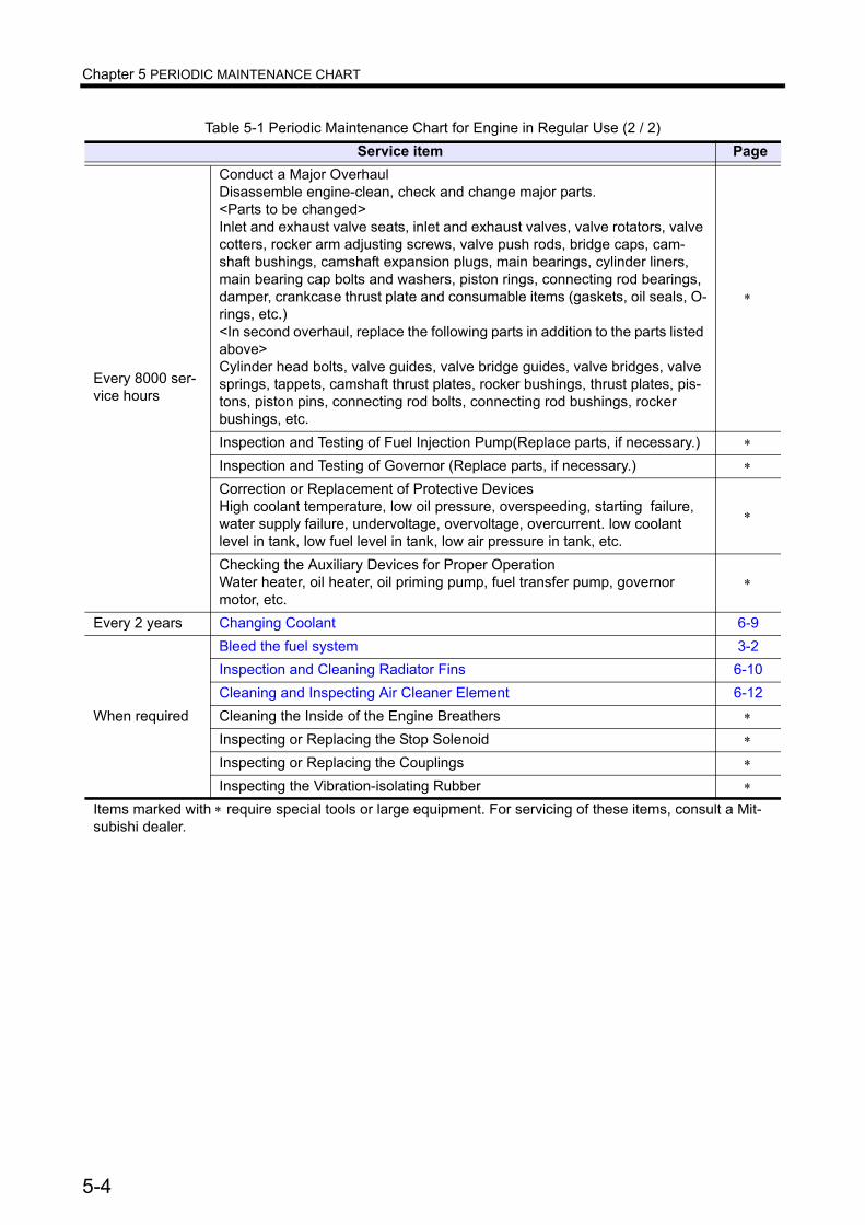
Chapter 5 PERIODIC MAINTENANCE CHART
Every 8000 ser-vice hours
Conduct a Major OverhaulDisassemble engine-clean, check and change major parts.<Parts to be changed>Inlet and exhaust valve seats, inlet and exhaust valves, valve rotators, valve cotters, rocker arm adjusting screws, valve push rods, bridge caps, cam-shaft bushings, camshaft expansion plugs, main bearings, cylinder liners, main bearing cap bolts and washers, piston rings, connecting rod bearings, damper, crankcase thrust plate and consumable items (gaskets, oil seals, O-rings, etc.)<In second overhaul, replace the following parts in addition to the parts listed above>Cylinder head bolts, valve guides, valve bridge guides, valve bridges, valve springs, tappets, camshaft thrust plates, rocker bushings, thrust plates, pis-tons, piston pins, connecting rod bolts, connecting rod bushings, rocker bushings, etc.
∗
Inspection and Testing of Fuel Injection Pump(Replace parts, if necessary.) ∗
Inspection and Testing of Governor (Replace parts, if necessary.) ∗
Correction or Replacement of Protective DevicesHigh coolant temperature, low oil pressure, overspeeding, starting failure, water supply failure, undervoltage, overvoltage, overcurrent. low coolant level in tank, low fuel level in tank, low air pressure in tank, etc.
∗
Checking the Auxiliary Devices for Proper OperationWater heater, oil heater, oil priming pump, fuel transfer pump, governor motor, etc.
∗
Every 2 years Changing Coolant 6-9
When required
Bleed the fuel system 3-2Inspection and Cleaning Radiator Fins 6-10Cleaning and Inspecting Air Cleaner Element 6-12Cleaning the Inside of the Engine Breathers ∗
Inspecting or Replacing the Stop Solenoid ∗
Inspecting or Replacing the Couplings ∗
Inspecting the Vibration-isolating Rubber ∗
Table 5-1 Periodic Maintenance Chart for Engine in Regular Use (2 / 2)Service item Page
Items marked with ∗ require special tools or large equipment. For servicing of these items, consult a Mit-subishi dealer.
5-4

Chapter 5 PERIODIC MAINTENANCE CHART
Periodic Maintenance Chart for Emergency EngineTable 5-2 Periodic Maintenance Chart for Emergency Engine (1 / 3)
Service item Page
Every week
Conducting External Inspection.(Check for leakage of fuel, oil and coolant.) 3−8
Checking the Fuel Level in the Fuel Tank 3−1
Checking Engine Oil Level 3-9Checking Coolant Level 3-10Inspection of Air Tank Air Pressure 3-11Check air cooler for water leaks. ∗
Conducting an Engine Maintenance Operation(Operate the engine under no load for 5 to 10 minutes.)Check for ease of starting, color of exhaust smoke, abnormal vibration, abnormal noise, abnormal smell and gauge indication" (oil pressure gauge, coolant temperature gauge, oil temperature gauge, exhaust temperature gauge, tachometer, etc.)"
∗
Every month
Inspection of Fuel Control Linkage Ball Joints 6-4Clean fuel filter (wire element type) - turn handle one or two times. −
Inspection of Engine Oil for Mixing of Fuel and Water 6-7Electrolyte level 6-14Check oil level in air compressor - add oil. −
Draining Water from Air Tank 6-15Conducting Engine Maintenance Operation(Operate the engine with more than 1/2 load for 15 to 30 minutes.)Check for ease of starting, color of exhaust smoke, abnormal vibration, abnormal noise, abnormal smell and gauge indication(oil pressure gauge, coolant temperature gauge, oil temperature gauge, exhaust temperature gauge, tachometer. etc.) Check fuel injection pump and hydraulic and electronic governor rack movement."
∗
Every 6 months
Checking LLC Concentration in the Coolant ∗
Cleaning the Inside of the Coolant Tank ∗
Every year
Basic block
Inspection of V-belt and Adjustment of Belt Tension 6-2Inspection of External Bolts and Nuts for Tightness, and Retighten If Necessary ∗
Inspection of Damper 6-3Inspection and Adjustment of Valve Clearance(Inspect the parts related to valve mechanism at the same time.) ∗
Inspection of Vibration-isolating Rubber ∗
Inspection of Foundation Bolts ∗
Inspection or Replacement of Couplings ∗
Fuel system
Drain water and sediment from fuel tank. ∗
Drain water from fuel filter (wire element type). ∗
Inspection and Adjustment of Fuel Injection Nozzle Spray Condition and Spray Pressure ∗
Inspection and Adjustment of Fuel Injection Timing ∗
Items marked with ¤ require special tools or large equipment. For servicing of these items, consult a Mit-subishi dealer.
5-5
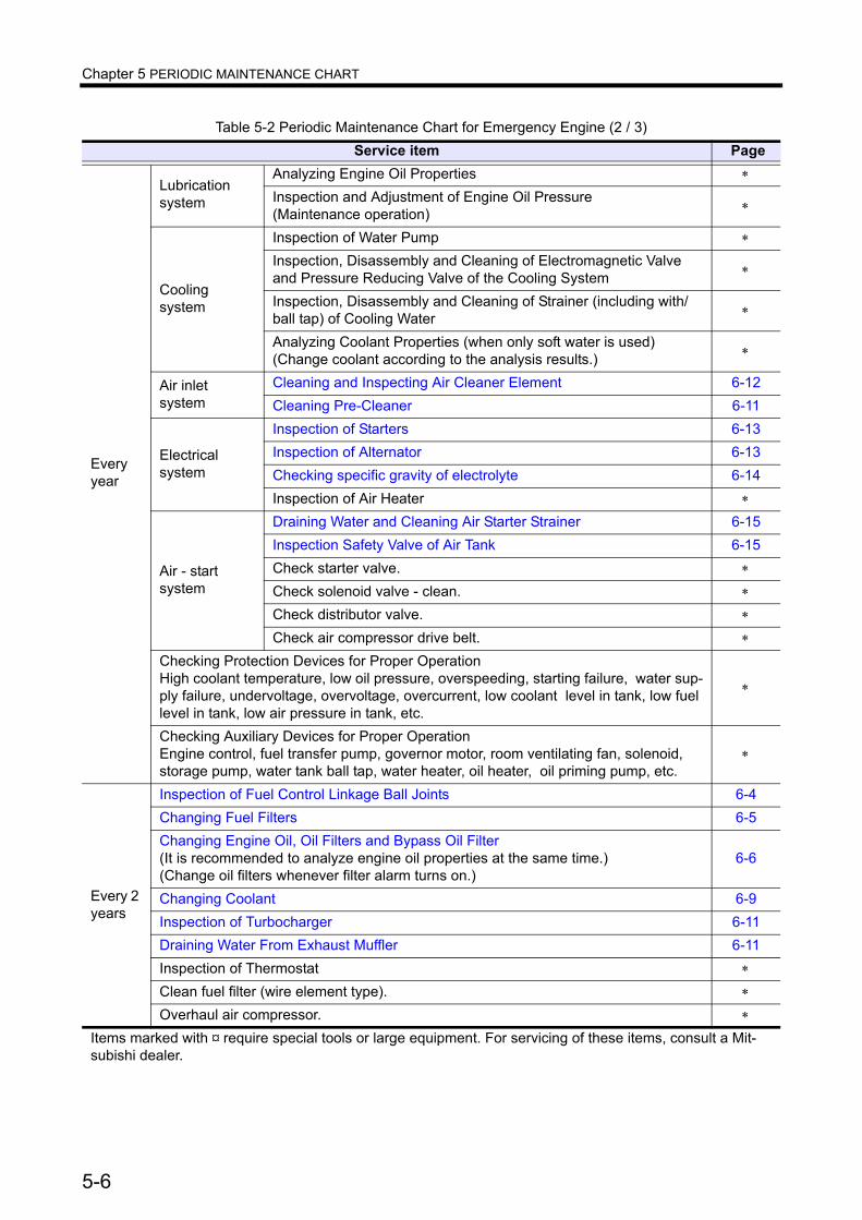
Chapter 5 PERIODIC MAINTENANCE CHART
Every year
Lubricationsystem
Analyzing Engine Oil Properties ∗
Inspection and Adjustment of Engine Oil Pressure(Maintenance operation) ∗
Cooling system
Inspection of Water Pump ∗
Inspection, Disassembly and Cleaning of Electromagnetic Valve and Pressure Reducing Valve of the Cooling System ∗
Inspection, Disassembly and Cleaning of Strainer (including with/ball tap) of Cooling Water ∗
Analyzing Coolant Properties (when only soft water is used)(Change coolant according to the analysis results.) ∗
Air inlet system
Cleaning and Inspecting Air Cleaner Element 6-12Cleaning Pre-Cleaner 6-11
Electricalsystem
Inspection of Starters 6-13Inspection of Alternator 6-13Checking specific gravity of electrolyte 6-14Inspection of Air Heater ∗
Air - startsystem
Draining Water and Cleaning Air Starter Strainer 6-15Inspection Safety Valve of Air Tank 6-15Check starter valve. ∗
Check solenoid valve - clean. ∗
Check distributor valve. ∗
Check air compressor drive belt. ∗
Checking Protection Devices for Proper OperationHigh coolant temperature, low oil pressure, overspeeding, starting failure, water sup-ply failure, undervoltage, overvoltage, overcurrent, low coolant level in tank, low fuel level in tank, low air pressure in tank, etc.
∗
Checking Auxiliary Devices for Proper OperationEngine control, fuel transfer pump, governor motor, room ventilating fan, solenoid, storage pump, water tank ball tap, water heater, oil heater, oil priming pump, etc.
∗
Every 2 years
Inspection of Fuel Control Linkage Ball Joints 6-4Changing Fuel Filters 6-5Changing Engine Oil, Oil Filters and Bypass Oil Filter(It is recommended to analyze engine oil properties at the same time.) (Change oil filters whenever filter alarm turns on.)
6-6
Changing Coolant 6-9Inspection of Turbocharger 6-11Draining Water From Exhaust Muffler 6-11Inspection of Thermostat ∗
Clean fuel filter (wire element type). ∗
Overhaul air compressor. ∗
Table 5-2 Periodic Maintenance Chart for Emergency Engine (2 / 3)Service item Page
Items marked with ¤ require special tools or large equipment. For servicing of these items, consult a Mit-subishi dealer.
5-6
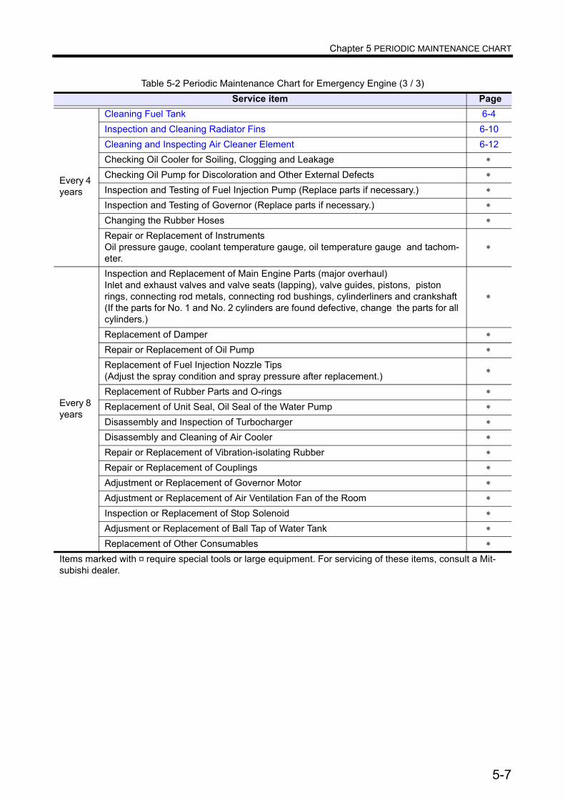
Chapter 5 PERIODIC MAINTENANCE CHART
Every 4 years
Cleaning Fuel Tank 6-4Inspection and Cleaning Radiator Fins 6-10Cleaning and Inspecting Air Cleaner Element 6-12Checking Oil Cooler for Soiling, Clogging and Leakage ∗
Checking Oil Pump for Discoloration and Other External Defects ∗
Inspection and Testing of Fuel Injection Pump (Replace parts if necessary.) ∗
Inspection and Testing of Governor (Replace parts if necessary.) ∗
Changing the Rubber Hoses ∗
Repair or Replacement of InstrumentsOil pressure gauge, coolant temperature gauge, oil temperature gauge and tachom-eter.
∗
Every 8 years
Inspection and Replacement of Main Engine Parts (major overhaul)Inlet and exhaust valves and valve seats (lapping), valve guides, pistons, piston rings, connecting rod metals, connecting rod bushings, cylinderliners and crankshaft (If the parts for No. 1 and No. 2 cylinders are found defective, change the parts for all cylinders.)
∗
Replacement of Damper ∗
Repair or Replacement of Oil Pump ∗
Replacement of Fuel Injection Nozzle Tips(Adjust the spray condition and spray pressure after replacement.) ∗
Replacement of Rubber Parts and O-rings ∗
Replacement of Unit Seal, Oil Seal of the Water Pump ∗
Disassembly and Inspection of Turbocharger ∗
Disassembly and Cleaning of Air Cooler ∗
Repair or Replacement of Vibration-isolating Rubber ∗
Repair or Replacement of Couplings ∗
Adjustment or Replacement of Governor Motor ∗
Adjustment or Replacement of Air Ventilation Fan of the Room ∗
Inspection or Replacement of Stop Solenoid ∗
Adjusment or Replacement of Ball Tap of Water Tank ∗
Replacement of Other Consumables ∗
Table 5-2 Periodic Maintenance Chart for Emergency Engine (3 / 3)Service item Page
Items marked with ¤ require special tools or large equipment. For servicing of these items, consult a Mit-subishi dealer.
5-7
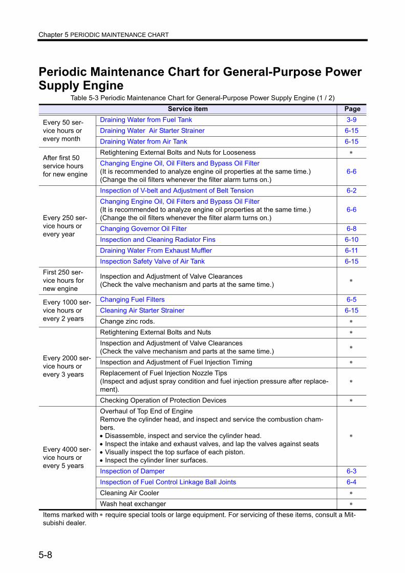
Chapter 5 PERIODIC MAINTENANCE CHART
Periodic Maintenance Chart for General-Purpose Power Supply Engine
Table 5-3 Periodic Maintenance Chart for General-Purpose Power Supply Engine (1 / 2)Service item Page
Every 50 ser-vice hours or every month
Draining Water from Fuel Tank 3-9Draining Water Air Starter Strainer 6-15Draining Water from Air Tank 6-15
After first 50 service hours for new engine
Retightening External Bolts and Nuts for Looseness ∗
Changing Engine Oil, Oil Filters and Bypass Oil Filter(It is recommended to analyze engine oil properties at the same time.)(Change the oil filters whenever the filter alarm turns on.)
6-6
Every 250 ser-vice hours or every year
Inspection of V-belt and Adjustment of Belt Tension 6-2Changing Engine Oil, Oil Filters and Bypass Oil Filter(It is recommended to analyze engine oil properties at the same time.)(Change the oil filters whenever the filter alarm turns on.)
6-6
Changing Governor Oil Filter 6-8Inspection and Cleaning Radiator Fins 6-10Draining Water From Exhaust Muffler 6-11Inspection Safety Valve of Air Tank 6-15
First 250 ser-vice hours for new engine
Inspection and Adjustment of Valve Clearances(Check the valve mechanism and parts at the same time.) ∗
Every 1000 ser-vice hours or every 2 years
Changing Fuel Filters 6-5Cleaning Air Starter Strainer 6-15Change zinc rods. ∗
Every 2000 ser-vice hours or every 3 years
Retightening External Bolts and Nuts ∗
Inspection and Adjustment of Valve Clearances(Check the valve mechanism and parts at the same time.) ∗
Inspection and Adjustment of Fuel Injection Timing ∗
Replacement of Fuel Injection Nozzle Tips(Inspect and adjust spray condition and fuel injection pressure after replace-ment).
∗
Checking Operation of Protection Devices ∗
Every 4000 ser-vice hours or every 5 years
Overhaul of Top End of EngineRemove the cylinder head, and inspect and service the combustion cham-bers.• Disassemble, inspect and service the cylinder head.• Inspect the intake and exhaust valves, and lap the valves against seats• Visually inspect the top surface of each piston.• Inspect the cylinder liner surfaces.
∗
Inspection of Damper 6-3Inspection of Fuel Control Linkage Ball Joints 6-4Cleaning Air Cooler ∗
Wash heat exchanger ∗
Items marked with ∗ require special tools or large equipment. For servicing of these items, consult a Mit-subishi dealer.
5-8

Chapter 5 PERIODIC MAINTENANCE CHART
Every 8000 ser-vice hours
Conducting Major OverhaulDisassemble engine-clean, check and change major parts. ∗
Inspection and Testing of Fuel Injection Pump(Replace parts, if necessary.) ∗
Inspection and Testing of Governor (Replace parts, if necessary.) ∗
Correction or Replacement of Protective DevicesHigh coolant temperature, low oil pressure, overspeeding, starting failure, water supply failure, undervoltage, overvoltage, overcurrent. low coolant level in tank, low fuel level in tank, low air pressure in tank, etc.
∗
Checking the Auxiliary Devices for Proper OperationWater heater, oil heater, oil priming pump, fuel transfer pump, governor motor, etc.
∗
Every 2 years Changing Coolant 6-9
When requiredBleed the fuel system 3-2Cleaning Pre-Cleaner 6-11Cleaning and Inspecting Air Cleaner Element 6-12
Table 5-3 Periodic Maintenance Chart for General-Purpose Power Supply Engine (2 / 2)Service item Page
Items marked with ∗ require special tools or large equipment. For servicing of these items, consult a Mit-subishi dealer.
5-9

Chapter 6 PERIODIC INSPECTION AND MAINTE-NANCE PROCEDURES
External ViewExternal Inspection
A fire can be caused by combustible materials placed near hot engine parts (exhaust manifolds and other exhaust gas passages) or battery, fuel leaks, and oil leaks. Check the engine exterior carefully. If an abnor-mality is found, be sure to repair or contact a Mitsubishi dealer.Before starting the engine, clean the top surface of the battery with wet cloth.
Inspect the engine exterior as described below.1 Make sure there is no combustible material near the engine or battery. Also, check to make sure the
engine and battery are clean.If combustible materials or waste are found near the engine or battery, remove them.
2 Check the entire engine for leakage of fuel, engine oil or coolant. If leaks are found, repair leakage or con-tact a Mitsubishi dealer.
3 Check the electrical wiring including the starters.
6-1

Chapter 6 PERIODIC INSPECTION AND MAINTENANCE PROCEDURES
Inspection of V-belt and Adjustment of Belt Tension
If damage or surface separation is found on the V-belt during inspection, replace the V-belt.Keep oil and grease away from the belt, since they may cause the belt to slip and shorten the service life.Excessive V-belt tension can cause rapid wear of the alternator bearing and shorten the service life of the belt. Adjust the belt tension accurately by following the procedures below.
Inspecting the V-belt1 Inspect the external appearance of the V-belt. If damage or surface separation is found on the V-belt,
replace the V-belt with a new belt.2 When force (approx. 98 to 147 N [10 to 15 kgf]) applied to the center section of the V-belt causes the belt
to deflect 10 to 15 mm [0.39 to 0.59 in.], the belt tension is appropriate.3 To adjust the belt tension, turn the adjusting rod.
Adjusting the V-belt tension (Alternator side)
1 Remove the alternator front cover and belt cover.
2 Loosen all retaining bolts on the alternator and adjusting rod.
3 Loosen the upper and lower lock nuts on the adjusting rod.
Note: Note that the lower nut on the adjusting rod has left-hand threads.
4 Turn the adjusting rod to adjust the V-belt ten-sion.
5 After the tension adjustment, tighten the upper and lower lock nuts.
6 Tighten all the retaining bolts on the alternator and adjusting rod.7 Reinstall the alternator front cover and belt cover.
Adjusting the V-belt tension (Water pump side)1 Remove the belt cover.2 Loosen all the retaining bolts on the tension pulley sliding plate.3 Loosen the lock nuts on the adjusting rod and tighten the bolts to have belt tension.4 Retighten all the retaining bolts on the tension pulley sliding plate.5 Reinstall the belt cover.
fig.6-1 Inspecting the V-belt and adjusting the belt tension
Adjusting rod
Lock bolt
6-2

Chapter 6 PERIODIC INSPECTION AND MAINTENANCE PROCEDURES
Inspection of DamperExternal inspection of damper
When installing a damper protective cover to the engine, do not use a cover that encloses the damper.Installation of a closed cover can cause damper damage due to heat.
Check the vibration damper for oil leakage, scratches, deformation, discoloration and peeling of paint.Check carefully for swelling on the cover (use a scale), oil leaks from the shim, discoloration and peeling of paint due to heat.Note: If the vibration damper is defective, consult a
Mitsubishi dealer.
Damper temperature managementFor proper operation, heat of the vibration damper must be dissipated from its surface to prevent excessive damper heating. Mitsubishi inspects each engine before shipment to ensure proper operating temperature of the vibration damper. However, the vibration damper temperature varies depending on ambient conditions. Therefore, observe the following suggestions and provide sufficient ventilation for the vibration damper and equipment.In the case of viscous damper of regular use engine, make sure the temperature of the outside damper sur-face does not exceed 90 °C [194 °F] after the engine is operated at the rated output for 1 hour, and emer-gency engine for 100 °C [212 °F]. In the case of viscous rubber damper of regular use engine, make sure the temperature does not exceed 80 °C [176 °F], and emergency engine for 90 °C [194 °F]. It is recommended to use the thermo label for temperature management of the vibration damper in regular use engine.
When installing a safety cover over the vibration damper, check ventilation carefully and make sure the damper temperature remains below the above temperature with the cover in place.
Table 6-1 Temperature Management with Thermo Label
Parts name Parts No.Temperature measuring
rangeThermo label 75-95
32522-0410075 to 95 °C[167 to 203 °F]
Thermo label 100-120
32522-04200100 to 120 °C[212 to 248 °F]
Thermo label 50-70
32522-0430050 to 70 °C [122 to 158 °F]
fig.6-2 Inspecting the damper
Cover
fig.6-3 Managing the damper temperature
6-3
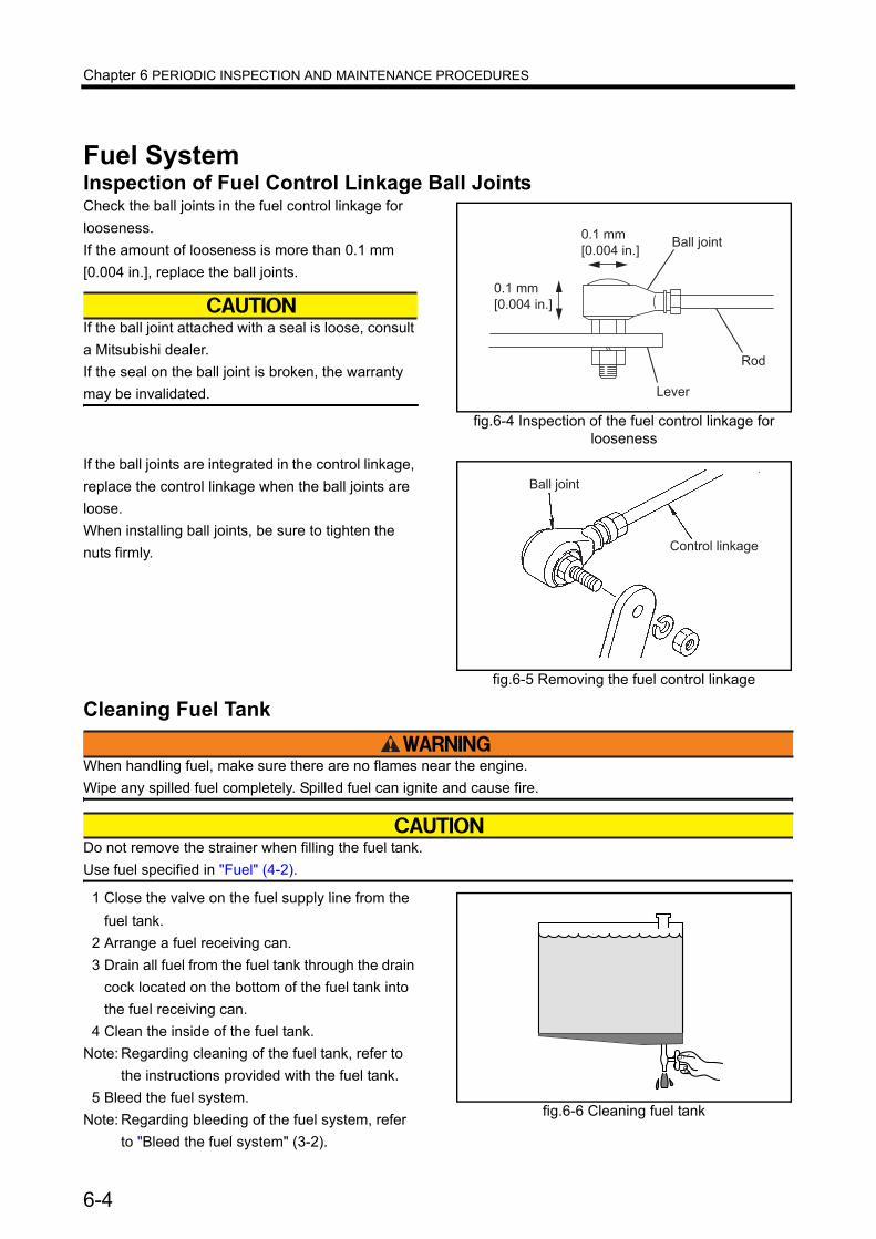
Chapter 6 PERIODIC INSPECTION AND MAINTENANCE PROCEDURES
Fuel SystemInspection of Fuel Control Linkage Ball JointsCheck the ball joints in the fuel control linkage for looseness.If the amount of looseness is more than 0.1 mm [0.004 in.], replace the ball joints.
If the ball joint attached with a seal is loose, consult a Mitsubishi dealer.If the seal on the ball joint is broken, the warranty may be invalidated.
If the ball joints are integrated in the control linkage, replace the control linkage when the ball joints are loose.When installing ball joints, be sure to tighten the nuts firmly.
Cleaning Fuel Tank
When handling fuel, make sure there are no flames near the engine.Wipe any spilled fuel completely. Spilled fuel can ignite and cause fire.
Do not remove the strainer when filling the fuel tank.Use fuel specified in "Fuel" (4-2).
1 Close the valve on the fuel supply line from the fuel tank.
2 Arrange a fuel receiving can.3 Drain all fuel from the fuel tank through the drain
cock located on the bottom of the fuel tank into the fuel receiving can.
4 Clean the inside of the fuel tank.Note: Regarding cleaning of the fuel tank, refer to
the instructions provided with the fuel tank.5 Bleed the fuel system.
Note: Regarding bleeding of the fuel system, refer to "Bleed the fuel system" (3-2).
fig.6-4 Inspection of the fuel control linkage for looseness
���� �����
�
�� ��
��� ��
������ ����
��� ��
������ ����
fig.6-5 Removing the fuel control linkage
Ball joint
Control linkage
fig.6-6 Cleaning fuel tank
6-4
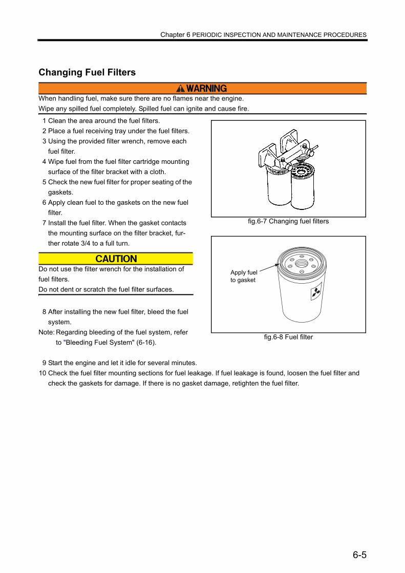
Chapter 6 PERIODIC INSPECTION AND MAINTENANCE PROCEDURES
Changing Fuel Filters
When handling fuel, make sure there are no flames near the engine.Wipe any spilled fuel completely. Spilled fuel can ignite and cause fire.
1 Clean the area around the fuel filters.2 Place a fuel receiving tray under the fuel filters.3 Using the provided filter wrench, remove each
fuel filter.4 Wipe fuel from the fuel filter cartridge mounting
surface of the filter bracket with a cloth.5 Check the new fuel filter for proper seating of the
gaskets.6 Apply clean fuel to the gaskets on the new fuel
filter.7 Install the fuel filter. When the gasket contacts
the mounting surface on the filter bracket, fur-ther rotate 3/4 to a full turn.
Do not use the filter wrench for the installation of fuel filters.Do not dent or scratch the fuel filter surfaces.
8 After installing the new fuel filter, bleed the fuel system.
Note: Regarding bleeding of the fuel system, refer to "Bleeding Fuel System" (6-16).
9 Start the engine and let it idle for several minutes.10 Check the fuel filter mounting sections for fuel leakage. If fuel leakage is found, loosen the fuel filter and
check the gaskets for damage. If there is no gasket damage, retighten the fuel filter.
fig.6-7 Changing fuel filters
fig.6-8 Fuel filter
Apply fuelto gasket
6-5

Chapter 6 PERIODIC INSPECTION AND MAINTENANCE PROCEDURES
Lubricating SystemChanging Engine Oil, Oil Filters and Bypass Oil Filter
To drain oil or change oil filters, wear gloves. Hot engine oil and parts may cause burns.
When changing engine oil, change the oil filters and bypass oil filter at the same time.It is recommended to analyze engine oil properties at the same time.
Also change the oil filters whenever the filter alarm turns on.
Draining engine oilTo ensure thorough drainage, drain engine oil while it is still warm after engine operation.Note: Do not suck out the engine oil when draining.
Changing oil filters and bypass oil filter1 Clean the area around the oil filters.2 Place an oil-receiving tray under the oil filters.3 Using the provided filter wrench, remove each
oil filter.Note: Check the filter elements in the removed oil
filter for metal particles. If metal particles are found, consult a Mitsubishi dealer. Also change the oil filters whenever the filter alarm turns on.
4 Wipe oil from the oil filter mounting surface on the filter alarm bracket with a cloth.
5 Check the new oil filter for proper seating of the gaskets.
6 Apply clean engine oil to the gaskets on the new oil filter.
7 Install the oil filter. When the gasket contacts the mounting surface on the filter bracket, further rotate 3/4 to a full turn.
Do not use the filter wrench for the installation of oil filters.Do not dent or scratch the oil filter cartridge sur-faces.
fig.6-9 Oil filters and bypass oil filter
Oil filter
By-pass oil filter
fig.6-10 Oil filter
Apply engine oil �to packing
6-6
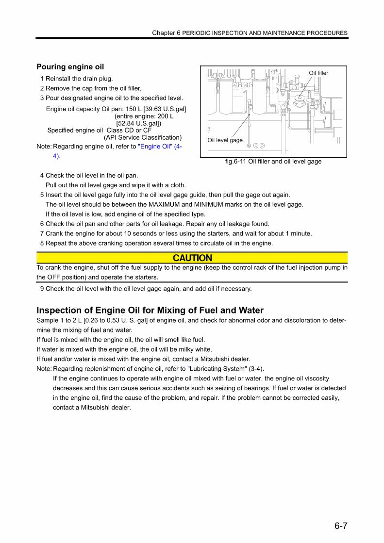
Chapter 6 PERIODIC INSPECTION AND MAINTENANCE PROCEDURES
Pouring engine oil1 Reinstall the drain plug.2 Remove the cap from the oil filler.3 Pour designated engine oil to the specified level.
Note: Regarding engine oil, refer to "Engine Oil" (4-4).
4 Check the oil level in the oil pan.Pull out the oil level gage and wipe it with a cloth.
5 Insert the oil level gage fully into the oil level gage guide, then pull the gage out again.The oil level should be between the MAXIMUM and MINIMUM marks on the oil level gage.If the oil level is low, add engine oil of the specified type.
6 Check the oil pan and other parts for oil leakage. Repair any oil leakage found.7 Crank the engine for about 10 seconds or less using the starters, and wait for about 1 minute.8 Repeat the above cranking operation several times to circulate oil in the engine.
To crank the engine, shut off the fuel supply to the engine (keep the control rack of the fuel injection pump inthe OFF position) and operate the starters.
9 Check the oil level with the oil level gage again, and add oil if necessary.
Inspection of Engine Oil for Mixing of Fuel and WaterSample 1 to 2 L [0.26 to 0.53 U. S. gal] of engine oil, and check for abnormal odor and discoloration to deter-mine the mixing of fuel and water.If fuel is mixed with the engine oil, the oil will smell like fuel.If water is mixed with the engine oil, the oil will be milky white.If fuel and/or water is mixed with the engine oil, contact a Mitsubishi dealer.Note: Regarding replenishment of engine oil, refer to "Lubricating System" (3-4).
If the engine continues to operate with engine oil mixed with fuel or water, the engine oil viscosity decreases and this can cause serious accidents such as seizing of bearings. If fuel or water is detected in the engine oil, find the cause of the problem, and repair. If the problem cannot be corrected easily, contact a Mitsubishi dealer.
fig.6-11 Oil filler and oil level gage
Oil filler
Oil level gage
Engine oil capacity Oil pan: 150 L [39.63 U.S.gal](entire engine: 200 L [52.84 U.S.gal])
Specified engine oil Class CD or CF(API Service Classification)
6-7
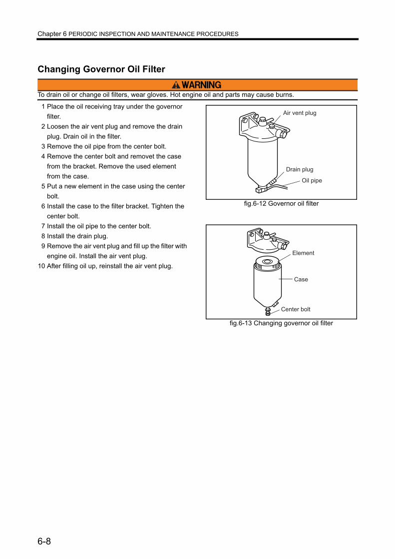
Chapter 6 PERIODIC INSPECTION AND MAINTENANCE PROCEDURES
Changing Governor Oil Filter
To drain oil or change oil filters, wear gloves. Hot engine oil and parts may cause burns.
1 Place the oil receiving tray under the governor filter.
2 Loosen the air vent plug and remove the drain plug. Drain oil in the filter.
3 Remove the oil pipe from the center bolt.4 Remove the center bolt and removet the case
from the bracket. Remove the used element from the case.
5 Put a new element in the case using the center bolt.
6 Install the case to the filter bracket. Tighten the center bolt.
7 Install the oil pipe to the center bolt.8 Install the drain plug.9 Remove the air vent plug and fill up the filter with
engine oil. Install the air vent plug.10 After filling oil up, reinstall the air vent plug.
fig.6-12 Governor oil filter
��� ���� ��
�� �� ��
�� ����
fig.6-13 Changing governor oil filter
������ ����
�����
����
6-8
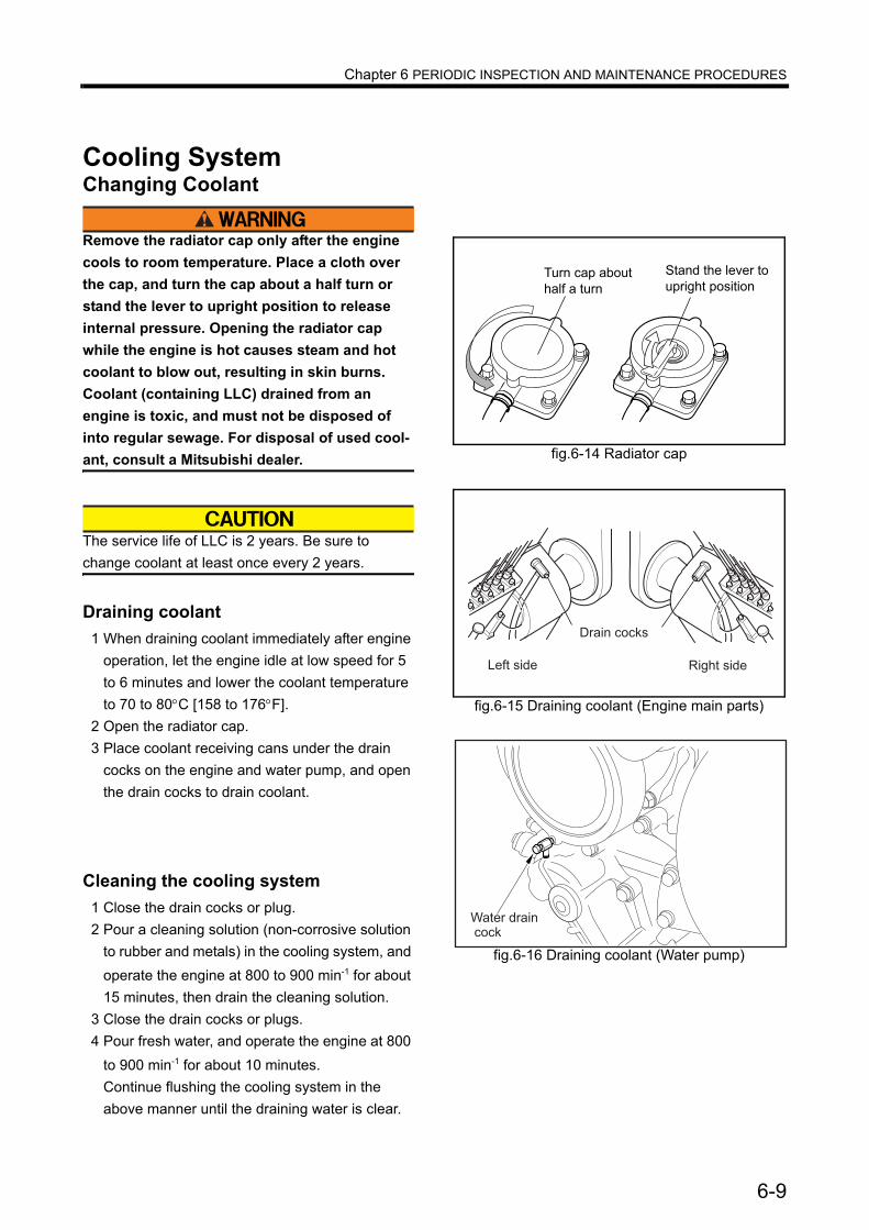
Chapter 6 PERIODIC INSPECTION AND MAINTENANCE PROCEDURES
Cooling SystemChanging Coolant
Remove the radiator cap only after the engine cools to room temperature. Place a cloth over the cap, and turn the cap about a half turn or stand the lever to upright position to release internal pressure. Opening the radiator cap while the engine is hot causes steam and hot coolant to blow out, resulting in skin burns.Coolant (containing LLC) drained from an engine is toxic, and must not be disposed of into regular sewage. For disposal of used cool-ant, consult a Mitsubishi dealer.
The service life of LLC is 2 years. Be sure to change coolant at least once every 2 years.
Draining coolant1 When draining coolant immediately after engine
operation, let the engine idle at low speed for 5 to 6 minutes and lower the coolant temperature to 70 to 80°C [158 to 176°F].
2 Open the radiator cap.3 Place coolant receiving cans under the drain
cocks on the engine and water pump, and open the drain cocks to drain coolant.
Cleaning the cooling system1 Close the drain cocks or plug.2 Pour a cleaning solution (non-corrosive solution
to rubber and metals) in the cooling system, and operate the engine at 800 to 900 min-1 for about 15 minutes, then drain the cleaning solution.
3 Close the drain cocks or plugs.4 Pour fresh water, and operate the engine at 800
to 900 min-1 for about 10 minutes.Continue flushing the cooling system in the above manner until the draining water is clear.
fig.6-14 Radiator cap
���� ��� ��� �
�� � � ���
���� �� ����
������ �����
fig.6-15 Draining coolant (Engine main parts)
����� ����
�� ��� ���� ���
fig.6-16 Draining coolant (Water pump)
Water drain cock
6-9
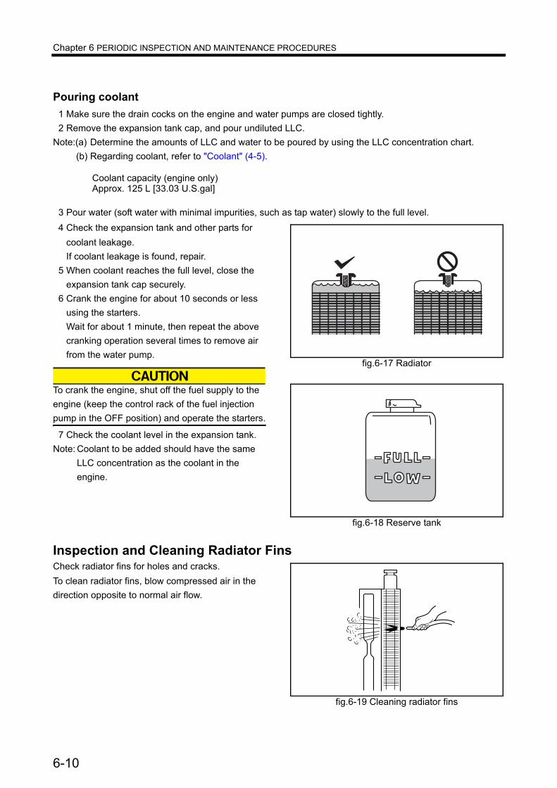
Chapter 6 PERIODIC INSPECTION AND MAINTENANCE PROCEDURES
Pouring coolant1 Make sure the drain cocks on the engine and water pumps are closed tightly.2 Remove the expansion tank cap, and pour undiluted LLC.
Note:(a) Determine the amounts of LLC and water to be poured by using the LLC concentration chart.(b) Regarding coolant, refer to "Coolant" (4-5).
3 Pour water (soft water with minimal impurities, such as tap water) slowly to the full level.4 Check the expansion tank and other parts for
coolant leakage.If coolant leakage is found, repair.
5 When coolant reaches the full level, close the expansion tank cap securely.
6 Crank the engine for about 10 seconds or less using the starters.Wait for about 1 minute, then repeat the above cranking operation several times to remove air from the water pump.
To crank the engine, shut off the fuel supply to the engine (keep the control rack of the fuel injection pump in the OFF position) and operate the starters.
7 Check the coolant level in the expansion tank.Note: Coolant to be added should have the same
LLC concentration as the coolant in the engine.
Inspection and Cleaning Radiator FinsCheck radiator fins for holes and cracks.To clean radiator fins, blow compressed air in the direction opposite to normal air flow.
fig.6-17 Radiator
fig.6-18 Reserve tank
fig.6-19 Cleaning radiator fins
Coolant capacity (engine only)Approx. 125 L [33.03 U.S.gal]
6-10

Chapter 6 PERIODIC INSPECTION AND MAINTENANCE PROCEDURES
Inlet Exhaust SystemInspection of Turbocharger
Make sure the engine is cool before inspecting the turbocharger. Also check that the compressor wheel is not rotating before inspection.
Disconnect the pipe from the air inlet side.Hold the compressor wheel nut by hand and turn the wheel to feel for looseness and listen for abnor-mal noise. Replace the bearings if the wheel is noisy or loose.Note: For replacement of the bearing, consult a Mit-
subishi dealer.
If the color of exhaust gas is abnormal, also achieve inspection for the turbocharger.
Draining Water From Exhaust Muffler
Do not touch the exhaust muffler immediately after the engine stops operation because it remains extremely hot for a while. Conduct work after the exhaust muffler cools.
Remove the drain plug and allow water to drain from the exhaust muffler.
Cleaning Pre-Cleaner
Do not service the air cleaner while the engine is running. Maintenance of the air cleaner while the engine is in operation can cause dust to enter the engine and result in rapid wear of parts, leading to a shorter service life.
Remove dust from the inlet side of the pre-cleaner installed to the silencer of the turbocharger. Be sure to keep the pre-cleaner clean to ensure optimum engine performance.
1 Remove the pre-cleaner from the silencer, and hand-wash the pre-cleaner with a mild detergent.
2 Rinse the pre-cleaner with clean water.3 After drying thoroughly, reinstall the pre-cleaner to the silencer.
Note: If the pre-cleaner is cracked or damaged, replace.
fig.6-20 Inspection of turbocharger
fig.6-21 Draining water from exhaust muffler
Drain plug
fig.6-22 Cleaning Pre-Cleaner
�����
������
���
�����
�������
������ ���������
6-11
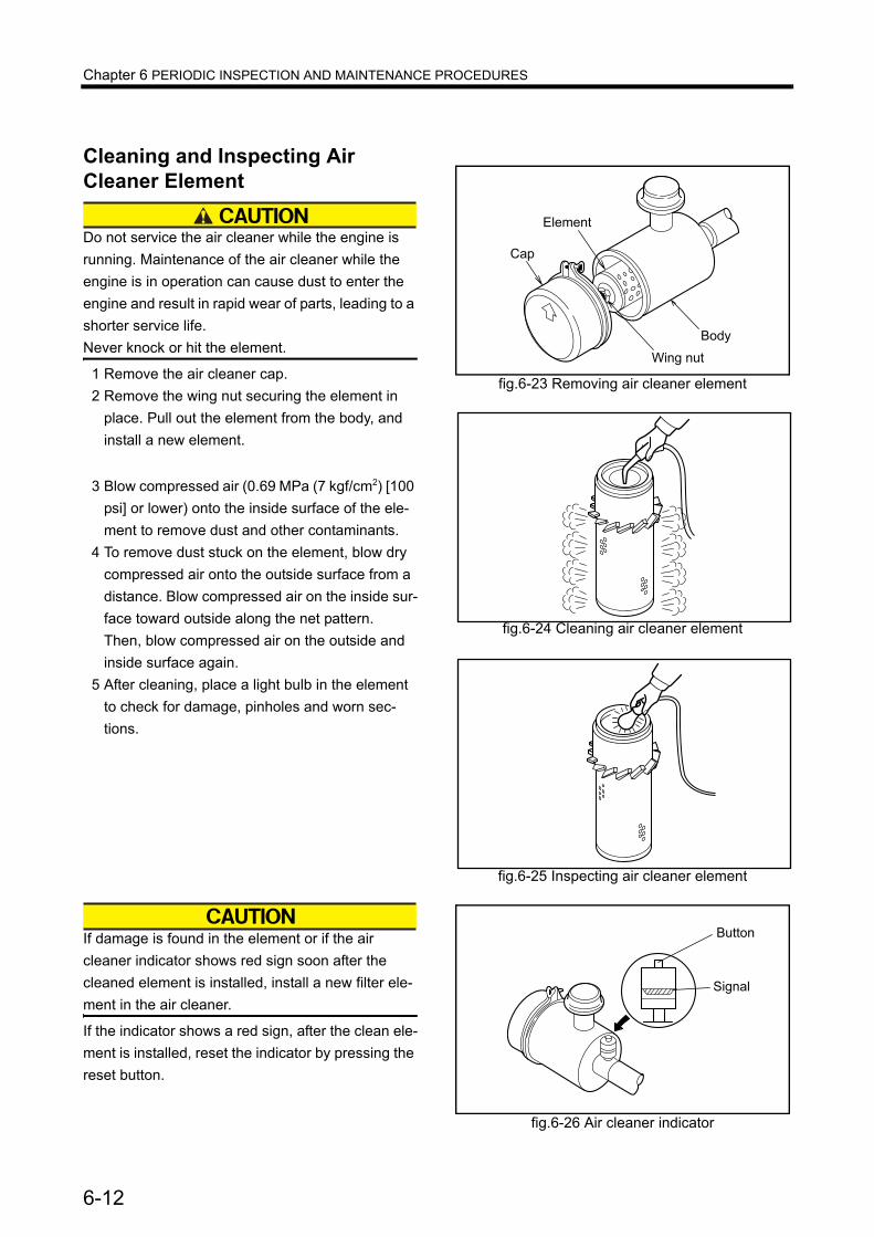
Chapter 6 PERIODIC INSPECTION AND MAINTENANCE PROCEDURES
Cleaning and Inspecting Air Cleaner Element
Do not service the air cleaner while the engine is running. Maintenance of the air cleaner while the engine is in operation can cause dust to enter the engine and result in rapid wear of parts, leading to a shorter service life.Never knock or hit the element.
1 Remove the air cleaner cap.2 Remove the wing nut securing the element in
place. Pull out the element from the body, and install a new element.
3 Blow compressed air (0.69 MPa (7 kgf/cm2) [100 psi] or lower) onto the inside surface of the ele-ment to remove dust and other contaminants.
4 To remove dust stuck on the element, blow dry compressed air onto the outside surface from a distance. Blow compressed air on the inside sur-face toward outside along the net pattern.Then, blow compressed air on the outside and inside surface again.
5 After cleaning, place a light bulb in the element to check for damage, pinholes and worn sec-tions.
If damage is found in the element or if the air cleaner indicator shows red sign soon after the cleaned element is installed, install a new filter ele-ment in the air cleaner.
If the indicator shows a red sign, after the clean ele-ment is installed, reset the indicator by pressing the reset button.
fig.6-23 Removing air cleaner element
���
�������
��
��� ���
fig.6-24 Cleaning air cleaner element
fig.6-25 Inspecting air cleaner element
fig.6-26 Air cleaner indicator
������
�����
6-12
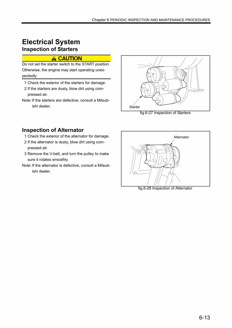
Chapter 6 PERIODIC INSPECTION AND MAINTENANCE PROCEDURES
Electrical SystemInspection of Starters
Do not set the starter switch to the START position. Otherwise, the engine may start operating unex-pectedly.
1 Check the exterior of the starters for damage.2 If the starters are dusty, blow dirt using com-
pressed air.Note: If the starters are defective, consult a Mitsub-
ishi dealer.
Inspection of Alternator1 Check the exterior of the alternator for damage.2 If the alternator is dusty, blow dirt using com-
pressed air.3 Remove the V-belt, and turn the pulley to make
sure it rotates smoothly.Note: If the alternator is defective, consult a Mitsub-
ishi dealer.
fig.6-27 Inspection of StartersStarter
fig.6-28 Inspection of Alternator
Alternator
6-13

Chapter 6 PERIODIC INSPECTION AND MAINTENANCE PROCEDURES
Checking Battery
If electrolyte is spilled on the eyes, skin or clothes, wash immediately with plenty of water. If electrolyte enters the eyes, flush immediately with lots of fresh water and see a physician.Do not use flames near the battery. When handling the battery, be careful of sparks generated by accidental shorting.Regarding other cautions in handling the battery, refer to "Caution Service Battery" (1-5).
Electrolyte levelElectrolyte evaporates during use and the fluid level gradually decreases. The fluid surface should be between the LOWER LEVEL and UPPER LEVEL lines. If there are no level lines on the battery, make sure that the fluid surface is about 10 to 15 mm [0.394 to 0.591 in.] above the top edges of the plate. If the fluid level is lower, remove the caps and add distilled water to the proper level.Note: When pouring fresh electrolyte, pour the fluid
carefully.
Checking specific gravity of electrolyte Check the specific gravity of the electrolyte. If the specific gravity measured at 20 °C [68 °F] is lower than 1.22, then charge the battery.
Table 6-2 Specific gravity of electrolyteSpecific gravity at 20°C [68°F] Condition Remedy
From 1.26 to 1.28 Fully charged -
From 1.22 to 1.26 Charged ChargeLess than 1.22 Discharged Charge
fig.6-29 Inspecting electrolyte level
�����
� ����
�����
�����
� ��� ��
����� �� � �� ����
����
�����
fig.6-30 Inspecting specific gravity of electrolyte
�����
�����������
�����
��������
����
��� ���
6-14

Chapter 6 PERIODIC INSPECTION AND MAINTENANCE PROCEDURES
Air Starter SystemDraining Water and Cleaning Air Starter Strainer
1 Close the starter valve handle of the air starter tank.
2 Remove the drain plug of air starter strainer and drain water from the air strainer.
3 Remove the cap and remove the filter from the cap.
4 Clean the filter with diesel fuel, then blow com-pressed air to dry.
5 Reinatall the air strainer as it is.6 Open the air starter handle slowly.
Draining Water from Air Tank
Slowly open the starting air handle of the air tank. If the handle is opened quickly, the engine can start abruptly and cause an unexpected accident.
1 Close the starting air handle of the air tank.2 Open the drain valve handle located under the
drain valve on the front side of the tank to drain accumulated water from the tank.
Note: The amount of drained water can vary depending on the relative humidity and air consumption.
3 Close the drain valve handle after draining water.4 Open the starting air handles slowly.
Inspection Safety Valve of Air TankCheck to make sure the safety valve opens to relieve pressure when the air pressure in the tank rises abnormally.
fig.6-31 Air starter strainer
Filter
Air starter inlet
Cap
PlugSpringPacking
Air starter outlet
fig.6-32 Draining water from air tank
Drain valve�handle
Starting �air handles
fig.6-33 Inspection safety valve of air tank
Safety valve
6-15
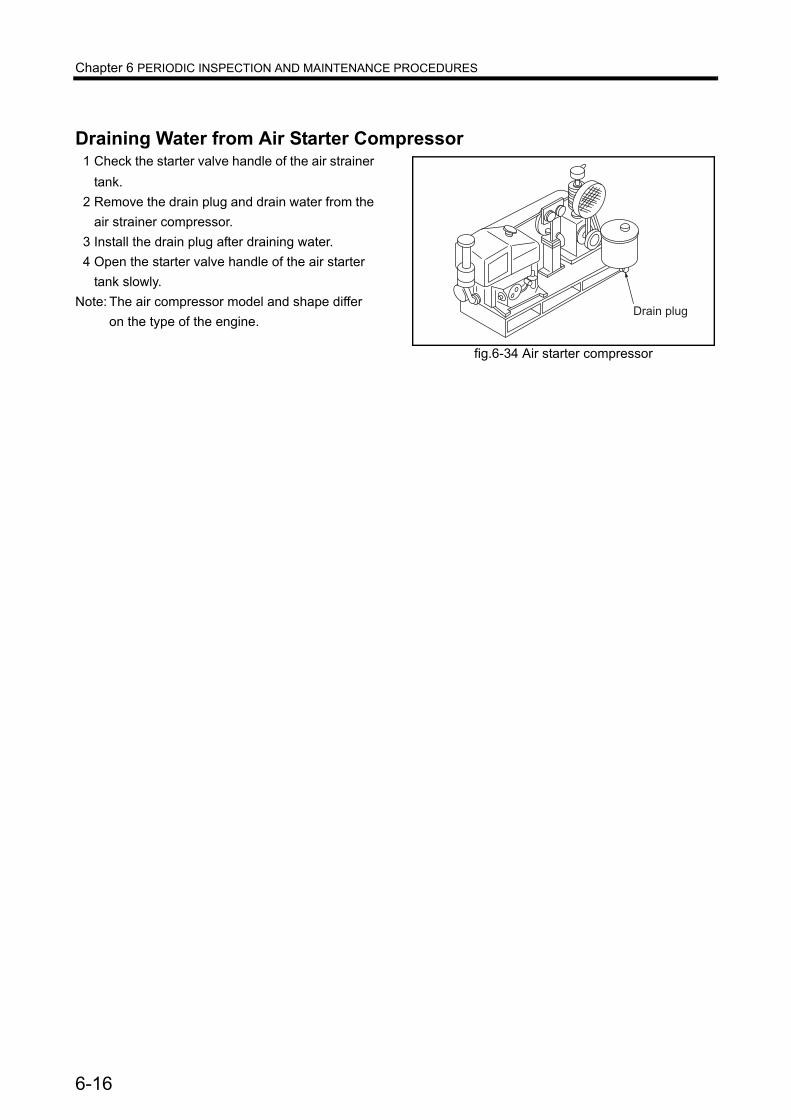
Chapter 6 PERIODIC INSPECTION AND MAINTENANCE PROCEDURES
Draining Water from Air Starter Compressor1 Check the starter valve handle of the air strainer
tank.2 Remove the drain plug and drain water from the
air strainer compressor.3 Install the drain plug after draining water.4 Open the starter valve handle of the air starter
tank slowly.Note: The air compressor model and shape differ
on the type of the engine.
fig.6-34 Air starter compressor
Drain plug
6-16

7-1
Chapter 7 LONG-TERM STORAGELong-term storageThe following describes the method to store the engine in a non-operable condition for more than three months and the method for storing the engine in an operable condition for more than three months.If the engine is not properly prepared for a long-term storage of more than three months, internal engine parts can rust and become damaged. Be sure to follow the directions below when storing the engine for an extended period of time.
Storing Engine in Non-operable Condition for More Than 3 MonthsPreparation for Storage
1 Drain engine oil, and pour rust-preventive oil (NP-10-1 to NP-10-3) into the engine.
2 Prepare a fuel mixture containing 50% rust-pre-ventive oil (NP-9), and pour it into the fuel tank.
3 Operate the engine at a speed of 800 to 1000 min-1 (idling) for 5 to 10 minutes under no load.
4 Immediately after stopping the engine, spray volatile corrosion inhibitor (V.C.I.) through the inlet side to prevent rust on the air intake sys-tem.
5 With the engine not in operation, drain the fuel mixture from the fuel tank.
6 Apply rust-preventive oil (NP-3) liberally on the exposed sections of the machine.
7 Seal air inlet, exhaust outlet, breather and other openings with adhesive cloth tape.
8 Loosen the V-belt.9 Wrap adhesive cloth tape on the terminals of the
starters and alternator, and seal the openings. Cover these sections with polyethylene sheet or processed polyethylene paper, and place desic-cants in the polyethylene covers.
10 Disconnect cables from the battery terminals, and charge the battery. Clean the terminals, apply a thin coat of grease, and store them in a cool and dry room.
11 Cover the entire engine.
Note:(a) Store the engine in a well-ventilated indoor location.
(b) Coolant does not need to be drained since it contains long life coolant. (Add long life coolant to increase the concentration between 30 and 60%.)
(c) Post a sign at an easily noticeable location to warn that the rust-preventive oil in the engine must be replaced with engine oil and the fuel tank must be filled with fuel before operating the engine.
(d) New engine oil may be used in place of rust-preventive oil (NP-10-1 to NP-10-3).
Maintenance during StorageCharge the battery once a month.After checking proper electrolyte level in the bat-tery, charge the battery.
Table 7-1 Recommended Rust-preventive Oil and Corrosion Inhibitor
JIS No. Recommended product Application
K2246
NP-3Nippon Oil Corpo-rationAnti Rust P-1400
Prevention of rust on exposed machine sur-faces
NP-9Nippon Oil Corpo-rationAnti Rust P-2100
Prevention of rust on fuel system
NP-10-2
Nippon Oil Corpo-rationAnti Rust P-230
Prevention of rust on lubri-cating sys-tem
Z1519 -
Ryoukou KagakuV.C.I.Dianavolatile corrosion inhibitor
Prevention of rust on air intake sys-tem
Chapter 7 LONG-TERM STORAGE
Using Engine after Storage1 Remove the cover from the engine.2 Connect a fully charged battery.3 Remove the covers from the starters and alter-
nator.4 Adjust the tension of the V-belt.
Note: Regarding adjustment of V-belt tension, refer to "Inspection of V-belt and Ajustment of Belt
Tension" (6-2)5 Remove sealing tapes from the openings of the
engine.6 Drain rust-preventive oil, and pour appropriate
engine oil.Note: Regarding engine oil, refer to "Engine Oil" (4-
4).7 Fill the fuel tank with fuel, and bleed the fuel
system.Note: Regarding bleeding of the fuel system, refer
to "Bleeding the fuel system" (3-2).8 Inspect all sections of the engine.9 Remove the rocker covers, and pour oil on the
valve mechanisms.10 Crank the engine for about 10 seconds, and
repeat the cranking operation 3 times at an interval of about 1 minute.
To crank the engine, shut off the fuel supply to the engine and operate the starters.
11 Make sure the engine oil pressure rises.
Starting the engine1 Start the engine.
With regards to starting the engine, refer to "Prepa-ration for Operation (Pre-Start Inspection)" (3-8).
2 Conduct a warm-up operation to circulate oil throughout the engine.
3 Apply load and increase the engine speed to the rated speed.
Storing Engine in Operable Con-dition for More Than 3 MonthsWhen the engine is not operated during storage of more than three months, internal engine parts can rust and lose oil film. As a result, the engine can seize when it is started after storage. To prevent this, the engine must be operated periodically for maintenance purposes during storage.
Operating Engine for Maintenance Pur-posesOperate the engine for maintenance purposes at least once a month by following the directions below.
1 With no fuel supplied to the engine (press the engine stop button to shut off fuel injection), operate the starters twice at intervals of about 15 seconds and check the engine oil pressure gage to make sure the oil pressure increases.
2 After the engine starts, operate under no load for 5 to 10 minutes.
7-2
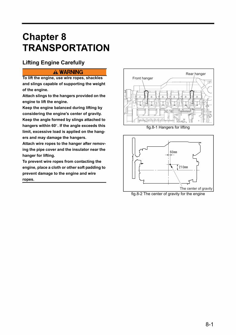
8-1
Chapter 8 TRANSPORTATIONLifting Engine Carefully
To lift the engine, use wire ropes, shackles and slings capable of supporting the weight of the engine.Attach slings to the hangers provided on the engine to lift the engine.Keep the engine balanced during lifting by considering the engine's center of gravity.Keep the angle formed by slings attached to hangers within 60°. If the angle exceeds this limit, excessive load is applied on the hang-ers and may damage the hangers.Attach wire ropes to the hanger after remov-ing the pipe cover and the insulator near the hanger for lifting.To prevent wire ropes from contacting the engine, place a cloth or other soft padding to prevent damage to the engine and wire ropes.
fig.8-1 Hangers for lifting
Front hangerRear hanger
fig.8-2 The center of gravity for the engineThe center of gravity


Chapter 9 TROUBLESHOOTINGGeneral Precautions
Contact a Mitsubishi Dealer for Repair ServiceRepairing a malfunctioning engine may require special equipment or potentially dangerous work, except for relatively simple procedures such as the change and addition of fuel, engine oil and coolant. In the event of the engine generates a malfunction, contact a Mitsubishi dealer.
Examination before WorkBefore troubleshooting, examine possible causes of the problem and try to see if the same problem has occurred in the past.Check the parts that may be causing the problem in the most efficient order.When disassembling a component, pay close attention to the disassembly sequence so that you can reassemble the component efficiently.
Notes Regarding ContaminationDust and foreign particles are the most common cause of rapid wear of parts.When disassembling a component, take measures to prevent dust and foreign particles from entering the component being disassembled.
Notes Regarding Parts HandlingHandle parts carefully.When replacing parts, use only genuine parts by referring to the parts catalog.
Work SafetyBe sure to use wrenches of correct size. Using a wrench of a wrong size not only damages nuts but can also cause personal injury.Use correct tools and perform work with utmost caution.Be sure to estimate the weight of the part being dis-mounted. If the removed part is too heavy, it may fall during lifting, causing damage to the part as well as personal injury.
9-1

Chapter 9 TROUBLESHOOTING
9-2
How to TroubleshootStarters Do Not Crank or Crank Slowly, Resulting in Start Failure
Starters Crank, But Engine Does Not Start
Table 9-1 Starters Do Not Crank or Crank Slowly, Resulting in Start FailureProblem Cause Remedy
Start failure
Electrical system
Blown fuse Change fuse.Faulty wire connection between bat-tery and starter switch Connect wire correctly.
Faulty wire connection between bat-tery, starters and starter switch Connect wire correctly.
Insufficiently charged batteryInspect and adjust V-belt tension. Refer to "Inspection of V-belt and Adjustment of Belt Tension" (6-2).
Specific gravity of battery fluid too low Charge battery.Faulty battery Install new battery.Faulty starter or starter relay Consult a Mitsubishi dealer.
Lubricating system Oil viscosity too high Use appropriate engine oil. Refer to
"Engine Oil" (4-4).
Fuel system
Air in fuel system Bleed fuel system.Refer to "Fuel Sys-tem" (3-1).
Low fuel level Add fuel.
Clogged fuel filters Change fuel filters.Refer to "Changing Fuel Filters" (6-5).
Faulty fuel feed pump Consult a Mitsubishi dealer.Faulty fuel injection pump Consult a Mitsubishi dealer.
Engine mechanical
Faulty moving parts(Interference between valves and pistons, or for-eign items in cylinders)
Consult a Mitsubishi dealer.
Table 9-2 Starters Crank, But Engine Does Not StartProblem Cause Remedy
Engine does not start
Fuel system
Empty fuel tank Add fuel, and bleed fuel system. Refer to "Fuel System" (3-1).
Damaged fuel pipe Consult a Mitsubishi dealer.
Loose fuel pipe connection Tighten connection. Consult a Mitsubishi dealer
Improper fuel Use proper fuel. Refer to "Fuel" (4-2).
Dust or water mixed in fuel Remove dust or water from fuel tank. Refer to "Cleaning Fuel Tank" (6-4).
Clogged fuel filters Replace fuel filters. Refer to "Changing Fuel Filters" (6-5).
Faulty fuel feed pump Consult a Mitsubishi dealer.Faulty fuel injection pump Consult a Mitsubishi dealer.
Air intake system Clogged air cleaner
Clean pre-cleaner. Refer to "Cleaning and Inspecting Air Cleaner Element" (6-12).
Engine mechanical
Compression pressure low (damaged cylinder liner, piston or piston ring, or faulty valve seat or nozzle packing seal)
Consult a Mitsubishi dealer.
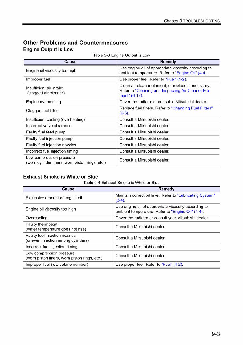
Chapter 9 TROUBLESHOOTING
9-3
Other Problems and CountermeasuresEngine Output is Low
Exhaust Smoke is White or Blue
Table 9-3 Engine Output is LowCause Remedy
Engine oil viscosity too high Use engine oil of appropriate viscosity according to ambient temperature. Refer to "Engine Oil" (4-4).
Improper fuel Use proper fuel. Refer to "Fuel" (4-2).
Insufficient air intake (clogged air cleaner)
Clean air cleaner element, or replace if necessary. Refer to "Cleaning and Inspecting Air Cleaner Ele-ment" (6-12).
Engine overcooling Cover the radiator or consult a Mitsubishi dealer.
Clogged fuel filter Replace fuel filters. Refer to "Changing Fuel Filters" (6-5).
Insufficient cooling (overheating) Consult a Mitsubishi dealer.Incorrect valve clearance Consult a Mitsubishi dealer.Faulty fuel feed pump Consult a Mitsubishi dealer.Faulty fuel injection pump Consult a Mitsubishi dealer.Faulty fuel injection nozzles Consult a Mitsubishi dealer.Incorrect fuel injection timing Consult a Mitsubishi dealer.Low compression pressure (worn cylinder liners, worn piston rings, etc.) Consult a Mitsubishi dealer.
Table 9-4 Exhaust Smoke is White or BlueCause Remedy
Excessive amount of engine oil Maintain correct oil level. Refer to "Lubricating System" (3-4).
Engine oil viscosity too high Use engine oil of appropriate viscosity according to ambient temperature. Refer to "Engine Oil" (4-4).
Overcooling Cover the radiator or consult your Mitsubishi dealer.Faulty thermostat (water temperature does not rise) Consult a Mitsubishi dealer.
Faulty fuel injection nozzles(uneven injection among cylinders) Consult a Mitsubishi dealer.
Incorrect fuel injection timing Consult a Mitsubishi dealer.Low compression pressure (worn piston liners, worn piston rings, etc.) Consult a Mitsubishi dealer.
Improper fuel (low cetane number) Use proper fuel. Refer to "Fuel" (4-2).

Chapter 9 TROUBLESHOOTING
9-4
Exhaust Smoke is Black or Dark Gray
Fuel Consumption is High
Engine Oil Consumption is High
Table 9-5 Exhaust Smoke is Black or Dark GrayCause Remedy
Improper fuel Use proper fuel. Refer to "Fuel" (4-2).Incorrect valve clearance Consult a Mitsubishi dealer.Faulty fuel feed pump Consult a Mitsubishi dealer.Low compression pressure (worn piston liners, worn piston rings, etc.) Consult a Mitsubishi dealer.
Insufficient intake air (improper ventilation, clogged air cleaner)
Clean air cleaner element, or replace if necessary. Refer to "Cleaning and Inspecting Air Cleaner Ele-ment" (6-12).
Incorrect fuel injection timing Consult a Mitsubishi dealer.Faulty fuel injection nozzles Consult a Mitsubishi dealer.Faulty fuel injection pump Consult a Mitsubishi dealer.
Table 9-6 Fuel Consumption is HighCause Remedy
Faulty fuel feed pump Consult a Mitsubishi dealer.Faulty fuel injection pump Consult a Mitsubishi dealer.Incorrect fuel injection timing Consult a Mitsubishi dealer.Improper fuel Use proper fuel. Refer to "Fuel" (4-2).Low compression pressure (worn piston liners, worn piston rings, etc.) Consult a Mitsubishi dealer.
Insufficient intake air (improper ventilation, clogged air cleaner)
Clean air cleaner element, or replace if necessary. Refer to "Cleaning and Inspecting Air Cleaner Ele-ment" (6-12).
Table 9-7 Engine Oil Consumption is HighCause Remedy
Excessive amount of engine oil Maintain correct oil level. Refer to "Lubricating System" (3-4).
Engine oil viscosity too lowUse engine oil of appropriate viscosity according to ambient tem-perature. Refer to "Engine Oil" (4-4).
Engine oil leakage Consult a Mitsubishi dealer.Worn cylinder liners, worn piston rings Consult a Mitsubishi dealer.Worn valve stem seals Consult a Mitsubishi dealer.

Chapter 9 TROUBLESHOOTING
9-5
Engine Overheats
Engine Oil Pressure is Faulty
Note:(a) If the problem cannot be corrected easily or when a problem other than those listed above occurs, consult a Mitsubishi dealer.
(b) When ordering replacement parts, provide the engine serial number. When requesting repair, pro-vide the engine serial number and service hour meter reading.
When Fuel Has Run OutWhen fuel runs out during engine operation, causing the engine to stop, follow the procedures below to restart the engine.
1 Return the starter switch to the OFF position.2 Add fuel to the fuel tank.
Note: Regarding filling of the fuel tank, refer to "Draining Water from Fuel Tank" (3-9).3 Bleed the fuel system.
Note: Regarding bleeding of the fuel system, refer to "Bleed the fuel system" (3-2).4 Restart the engine.
Note: Regarding starting of the engine, refer to "Preparations for Operation (Pre-Start Inspection)" (3-8).
Table 9-8 Engine OverheatsCause Remedy
Radiator, heat exchanger leakage Consult a Mitsubishi dealer.Low coolant level Add coolant.Faulty water pump Consult a Mitsubishi dealer.Faulty thermostat Consult a Mitsubishi dealer.
Table 9-9 Engine Oil Pressure is FaultyCause Remedy
Insufficient amount of engine oil Maintain correct oil level. Refer to "Lubricating System" (3-4).
Engine oil viscosity too low Use engine oil of appropriate viscosity according to ambient tempera-ture.Refer to "Engine Oil" (4-4).
Clogged oil filter Replace oil filters. Refer to "Changing Engine Oil, Oil Filters and Bypass Oil Filter" (6-6).
Faulty oil pump Consult a Mitsubishi dealer.Faulty relief valve Consult a Mitsubishi dealer.Faulty oil pressure sensor Consult a Mitsubishi dealer.

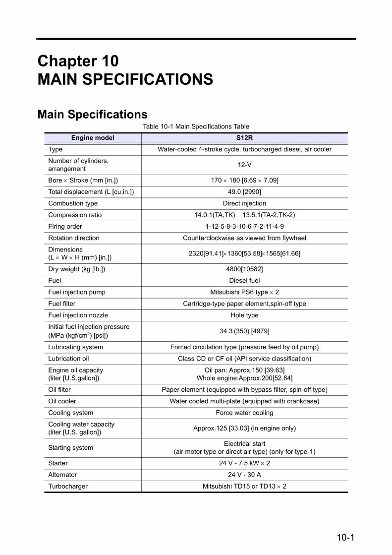
10-1
Chapter 10 MAIN SPECIFICATIONS
Main SpecificationsTable 10-1 Main Specifications Table
Engine model S12R
Type Water-cooled 4-stroke cycle, turbocharged diesel, air cooler
Number of cylinders, arrangement 12-V
Bore × Stroke (mm [in.]) 170 × 180 [6.69 × 7.09]
Total displacement (L [cu.in.]) 49.0 [2990]
Combustion type Direct injection
Compression ratio 14.0:1(TA,TK) 13.5:1(TA-2,TK-2)
Firing order 1-12-5-8-3-10-6-7-2-11-4-9
Rotation direction Counterclockwise as viewed from flywheel
Dimensions (L × W × H (mm) [in.]) 2320[91.41]×1360[53.58]×1565[61.66]
Dry weight (kg [lb.]) 4800[10582]
Fuel Diesel fuel
Fuel injection pump Mitsubishi PS6 type × 2
Fuel filter Cartridge-type paper element,spin-off type
Fuel injection nozzle Hole type
Initial fuel injection pressure (MPa (kgf/cm2) [psi])
34.3 (350) [4979]
Lubricating system Forced circulation type (pressure feed by oil pump)
Lubrication oil Class CD or CF oil (API service classification)
Engine oil capacity (liter [U.S.gallon])
Oil pan: Approx.150 [39.63]Whole engine:Approx.200[52.84]
Oil filter Paper element (equipped with bypass filter, spin-off type)
Oil cooler Water cooled multi-plate (equipped with crankcase)
Cooling system Force water cooling
Cooling water capacity (liter [U.S. gallon]) Approx.125 [33.03] (in engine only)
Starting system Electrical start(air motor type or direct air type) (only for type-1)
Starter 24 V - 7.5 kW × 2
Alternator 24 V - 30 A
Turbocharger Mitsubishi TD15 or TD13 × 2
