user’s manual - asuspcb1.… · asus p2b user’s manual 3 asus contact information asustek...
TRANSCRIPT

R
P2BPentium® II Motherboard
USER’S MANUAL

2 ASUS P2B User’s Manual
USER'S NOTICE
Product Name: ASUS P2BManual Revision: 1.02+ E307Release Date: March 1999
No part of this manual, including the products and software described in it, may be repro-duced, transmitted, transcribed, stored in a retrieval system, or translated into any language inany form or by any means, except documentation kept by the purchaser for backup purposes,without the express written permission of ASUSTeK COMPUTER INC. (“ASUS”).
ASUS PROVIDES THIS MANUAL “AS IS” WITHOUT WARRANTY OF ANY KIND,EITHER EXPRESS OR IMPLIED, INCLUDING BUT NOT LIMITED TO THE IMPLIEDWARRANTIES OR CONDITIONS OF MERCHANTABILITY OR FITNESS FOR A PAR-TICULAR PURPOSE. IN NO EVENT SHALL ASUS, ITS DIRECTORS, OFFICERS,EMPLOYEES OR AGENTS BE LIABLE FOR ANY INDIRECT, SPECIAL, INCIDEN-TAL, OR CONSEQUENTIAL DAMAGES (INCLUDING DAMAGES FOR LOSS OFPROFITS, LOSS OF BUSINESS, LOSS OF USE OR DATA, INTERRUPTION OF BUSI-NESS AND THE LIKE), EVEN IF ASUS HAS BEEN ADVISED OF THE POSSIBILITYOF SUCH DAMAGES ARISING FROM ANY DEFECT OR ERROR IN THIS MANUALOR PRODUCT.
Product warranty or service will not be extended if: (1) the product is repaired, modified oraltered, unless such repair, modification of alteration is authorized in writing by ASUS; or (2)the serial number of the product is defaced or missing.
Products and corporate names appearing in this manual may or may not be registered trade-marks or copyrights of their respective companies, and are used only for identification orexplanation and to the owners’ benefit, without intent to infringe.
• Intel, LANDesk, and Pentium are registered trademarks of Intel Corporation.• IBM and OS/2 are registered trademarks of International Business Machines.• Symbios is a registered trademark of Symbios Logic Corporation.• Windows and MS-DOS are registered trademarks of Microsoft Corporation.• Adobe and Acrobat are registered trademarks of Adobe Systems Incorporated.
The product name and revision number are both printed on the product itself. Manual revi-sions are released for each product design represented by the digit before and after the periodof the manual revision number. Manual updates are represented by the third digit in the manualrevision number.
For previous or updated manuals, BIOS, drivers, or product release information, contact ASUSat http://www.asus.com.tw or through any of the means indicated on the following page.
SPECIFICATIONS AND INFORMATION CONTAINED IN THIS MANUAL ARE FUR-NISHED FOR INFORMATIONAL USE ONLY, AND ARE SUBJECT TO CHANGE ATANY TIME WITHOUT NOTICE, AND SHOULD NOT BE CONSTRUED AS A COM-MITMENT BY ASUS. ASUS ASSUMES NO RESPONSIBILITY OR LIABILITY FORANY ERRORS OR INACCURACIES THAT MAY APPEAR IN THIS MANUAL, INCLUD-ING THE PRODUCTS AND SOFTWARE DESCRIBED IN IT.
Copyright © 1999 ASUSTeK COMPUTER INC. All Rights Reserved.

ASUS P2B User’s Manual 3
ASUS CONTACT INFORMATIONASUSTeK COMPUTER INC. (Asia-Pacific)MarketingAddress: 150 Li-Te Road, Peitou, Taipei, Taiwan 112Telephone: +886-2-2894-3447Fax: +886-2-2894-3449Email: [email protected]
Technical SupportTel (English): +886-2-2894-3447 ext. 706Tel (Chinese): +886-2-2894-3447 ext. 111Fax: +886-2-2895-9254Email: [email protected]: news2.asus.com.twWWW: www.asus.com.twFTP: ftp.asus.com.tw/pub/ASUS
ASUS COMPUTER INTERNATIONAL (America)MarketingAddress: 6737 Mowry Avenue, Mowry Business Center, Building 2
Newark, CA 94560, USAFax: +1-510-608-4555Email: [email protected]
Technical SupportFax: +1-510-608-4555BBS: +1-510-739-3774Email: [email protected]: www.asus.comFTP: ftp.asus.com.tw/pub/ASUS
ASUS COMPUTER GmbH (Europe)MarketingAddress: Harkort Str. 25, 40880 Ratingen, BRD, GermanyTelephone: 49-2102-445011Fax: 49-2102-442066Email: [email protected]
Technical SupportHotline: 49-2102-499712BBS: 49-2102-448690Email: [email protected]: www.asuscom.deFTP: ftp.asuscom.de/pub/ASUSCOM
4 ASUS P2B User’s Manual
CONTENTS
I. INTRODUCTION............................................................................... 7
How this Manual is Organized ........................................................... 7Item Checklist ..................................................................................... 7
II. FEATURES ........................................................................................ 8
Features of the ASUS P2B Motherboard ............................................ 8The ASUS P2B Motherboard .......................................................... 9
III. HARDWARE SETUP .................................................................... 10
Layout of the ASUS P2B Motherboard ............................................ 10Installation Steps ............................................................................... 12Jumpers ............................................................................................. 12
Jumper Settings ............................................................................. 13System Memory (DIMM) ................................................................. 17
SPD Support ................................................................................ 17DIMM Memory Installation Procedures: .................................... 18
Central Processing Unit (CPU) ......................................................... 19Universal Retention Mechanism ................................................. 19Heatsinks ..................................................................................... 19
Installing the Processor ................................................................. 20ASUS Smart Thermal Solutions ................................................. 22Recommended Heatsinks for Slot 1 Processors .......................... 23
Expansion Cards ............................................................................... 24Expansion Card Installation Procedure ....................................... 24Assigning IRQs for Expansion Cards ......................................... 24Assigning DMA Channels for ISA Cards ................................... 25ISA Cards and Hardware Monitor ............................................... 25
External Connectors .......................................................................... 26Power Connection Procedures .......................................................... 33Power Connection Procedures .......................................................... 33
ASUS P2B User’s Manual 5
CONTENTSIV. BIOS SETUP ................................................................................... 34
Managing and Updating Your BIOS ................................................. 34Upon First Use of the Computer System....................................... 34Updating BIOS Procedures ........................................................... 35Managing and Updating Your Motherboard’s BIOS ..................... 36
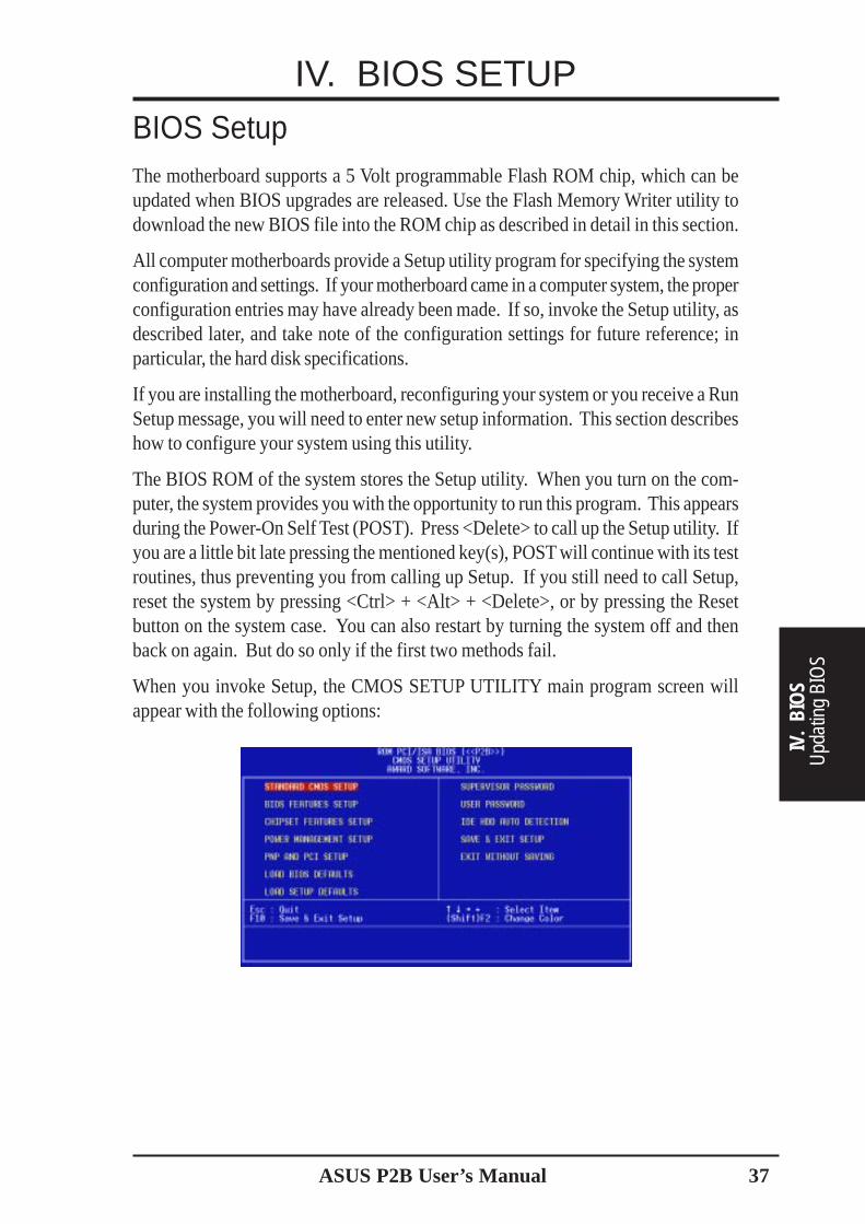
BIOS Setup ....................................................................................... 37Load Defaults .............................................................................. 38
Standard CMOS Setup .................................................................. 38Details of Standard CMOS Setup: .............................................. 38
BIOS Features Setup ..................................................................... 41Details of BIOS Features Setup .................................................. 41
Chipset Features Setup .................................................................. 44Details of Chipset Features Setup ............................................... 44
Power Management Setup ............................................................. 47Details of Power Management Setup .......................................... 47
PNP and PCI Setup ........................................................................ 50Details of PNP and PCI Setup ..................................................... 50
Load BIOS Defaults ...................................................................... 52Load Setup Defaults ...................................................................... 52Supervisor Password and User Password ...................................... 53IDE HDD Auto Detection ............................................................. 54Save & Exit Setup ......................................................................... 55Exit Without Saving ...................................................................... 55
V. SUPPORT SOFTWARE ................................................................. 56
Desktop Management Interface (DMI) ............................................. 56Introducing the ASUS DMI Configuration Utility ...................... 56System Requirements .................................................................. 56Using the ASUS DMI Configuration Utility ............................... 57
VI. APPENDIX ..................................................................................... 59
The ASUS CIDB Chassis Intrusion Sensor Module ......................... 59The ASUS S370 CPU Card .............................................................. 61ASUS PCI-L101 Fast Ethernet Card ................................................ 63Glossary ............................................................................................ 65
6 ASUS P2B User’s Manual
FCC & DOC COMPLIANCEFederal Communications Commission StatementThis device complies with FCC Rules Part 15. Operation is subject to the followingtwo conditions:
• This device may not cause harmful interference, and• This device must accept any interference received, including interference that
may cause undesired operation.
This equipment has been tested and found to comply with the limits for a Class Bdigital device, pursuant to Part 15 of the FCC Rules. These limits are designed toprovide reasonable protection against harmful interference in a residential installa-tion. This equipment generates, uses and can radiate radio frequency energy and, ifnot installed and used in accordance with manufacturer's instructions, may causeharmful interference to radio communications. However, there is no guarantee thatinterference will not occur in a particular installation. If this equipment does causeharmful interference to radio or television reception, which can be determined byturning the equipment off and on, the user is encouraged to try to correct the inter-ference by one or more of the following measures:
• Re-orient or relocate the receiving antenna.• Increase the separation between the equipment and receiver.• Connect the equipment to an outlet on a circuit different from that to which
the receiver is connected.• Consult the dealer or an experienced radio/TV technician for help.
WARNING! Any changes or modifications to this product not expressly ap-proved by the manufacturer could void any assurances of safety or performanceand could result in violation of Part 15 of the FCC Rules.
Canadian Department of Communications StatementThis digital apparatus does not exceed the Class B limits for radio noise emissionsfrom digital apparatus set out in the Radio Interference Regulations of the Cana-dian Department of Communications.
This Class B digital apparatus complies with Canadian ICES-003.
Cet appareil numérique de la classe B est conforme à la norme NMB-003 du Canada.

ASUS P2B User’s Manual 7
I. INTRODUCTION
I. IN
TRO
DUCT
ION
Man
ual /
Che
cklis
tHow this Manual is OrganizedThis manual is divided into the following sections:
I. Introduction: Manual information and checklistII. Features: Information and specifications concerning this productIII. Hardware Setup: Instructions on setting up the motherboardIV. BIOS Setup: Instructions on setting up the BIOS softwareV. Support Software: Information on the included support softwareVI. Appendix Optional items and general reference
Item ChecklistPlease check that your package is complete. If you discover damaged or missingitems, please contact your retailer.
(1) ASUS Motherboard
(1) Universal Retention Mechanism for SECC/SECC2/SEPP
(1) IDE ribbon cable for master and slave drives
(1) Floppy ribbon cable for (1) 5.25inch floppy and (2) 3.5inch floppies
(1) Bag of spare jumper caps
(1) Support CD with drivers and utilities
(1) User’s manual
S-P2FAN or P2T-Cable for Slot 1 processors
IrDA-compliant infrared module (optional)
ASUS PCI-L101 Wake-on-LAN 10/100 Ethernet Card (optional)
ASUS P2B User’s Manual8
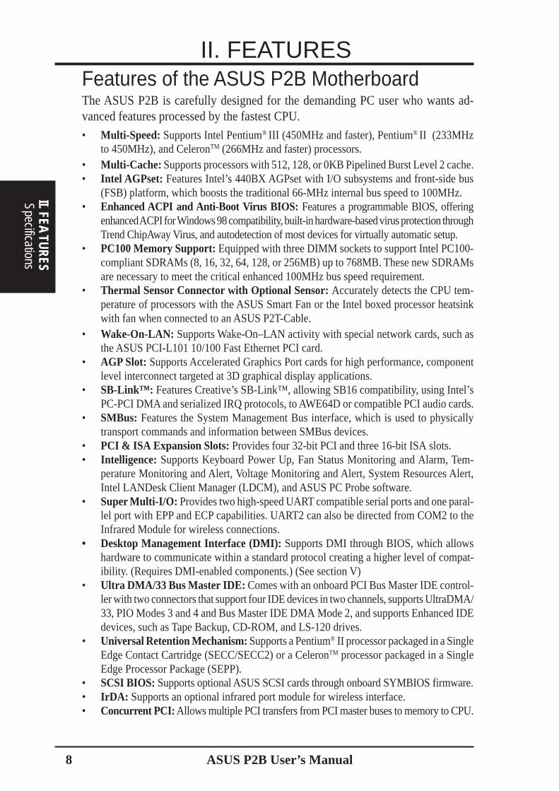
Features of the ASUS P2B MotherboardThe ASUS P2B is carefully designed for the demanding PC user who wants ad-vanced features processed by the fastest CPU.
• Multi-Speed: Supports Intel Pentium® III (450MHz and faster), Pentium® II (233MHzto 450MHz), and CeleronTM (266MHz and faster) processors.
• Multi-Cache: Supports processors with 512, 128, or 0KB Pipelined Burst Level 2 cache.• Intel AGPset: Features Intel’s 440BX AGPset with I/O subsystems and front-side bus
(FSB) platform, which boosts the traditional 66-MHz internal bus speed to 100MHz.• Enhanced ACPI and Anti-Boot Virus BIOS: Features a programmable BIOS, offering
enhanced ACPI for Windows 98 compatibility, built-in hardware-based virus protection throughTrend ChipAway Virus, and autodetection of most devices for virtually automatic setup.
• PC100 Memory Support: Equipped with three DIMM sockets to support Intel PC100-compliant SDRAMs (8, 16, 32, 64, 128, or 256MB) up to 768MB. These new SDRAMsare necessary to meet the critical enhanced 100MHz bus speed requirement.
• Thermal Sensor Connector with Optional Sensor: Accurately detects the CPU tem-perature of processors with the ASUS Smart Fan or the Intel boxed processor heatsinkwith fan when connected to an ASUS P2T-Cable.
• Wake-On-LAN: Supports Wake-On–LAN activity with special network cards, such asthe ASUS PCI-L101 10/100 Fast Ethernet PCI card.
• AGP Slot: Supports Accelerated Graphics Port cards for high performance, componentlevel interconnect targeted at 3D graphical display applications.
• SB-Link™: Features Creative’s SB-Link™, allowing SB16 compatibility, using Intel’sPC-PCI DMA and serialized IRQ protocols, to AWE64D or compatible PCI audio cards.
• SMBus: Features the System Management Bus interface, which is used to physicallytransport commands and information between SMBus devices.
• PCI & ISA Expansion Slots: Provides four 32-bit PCI and three 16-bit ISA slots.• Intelligence: Supports Keyboard Power Up, Fan Status Monitoring and Alarm, Tem-
perature Monitoring and Alert, Voltage Monitoring and Alert, System Resources Alert,Intel LANDesk Client Manager (LDCM), and ASUS PC Probe software.
• Super Multi-I/O: Provides two high-speed UART compatible serial ports and one paral-lel port with EPP and ECP capabilities. UART2 can also be directed from COM2 to theInfrared Module for wireless connections.
• Desktop Management Interface (DMI): Supports DMI through BIOS, which allowshardware to communicate within a standard protocol creating a higher level of compat-ibility. (Requires DMI-enabled components.) (See section V)
• Ultra DMA/33 Bus Master IDE: Comes with an onboard PCI Bus Master IDE control-ler with two connectors that support four IDE devices in two channels, supports UltraDMA/33, PIO Modes 3 and 4 and Bus Master IDE DMA Mode 2, and supports Enhanced IDEdevices, such as Tape Backup, CD-ROM, and LS-120 drives.
• Universal Retention Mechanism: Supports a Pentium® II processor packaged in a SingleEdge Contact Cartridge (SECC/SECC2) or a CeleronTM processor packaged in a SingleEdge Processor Package (SEPP).
• SCSI BIOS: Supports optional ASUS SCSI cards through onboard SYMBIOS firmware.• IrDA: Supports an optional infrared port module for wireless interface.• Concurrent PCI: Allows multiple PCI transfers from PCI master buses to memory to CPU.
II. FEATURES
SpecificationsII. FEA
TURES
ASUS P2B User’s Manual 9
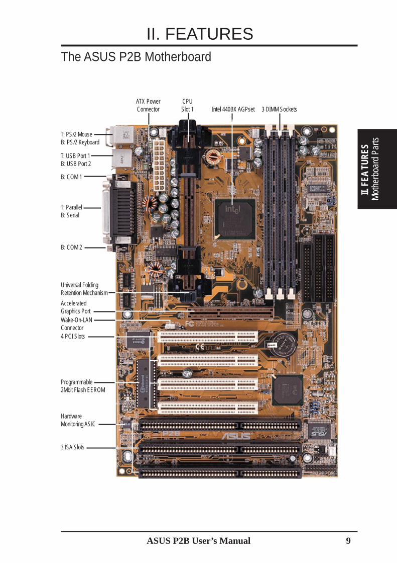
The ASUS P2B Motherboard
II. FEATURES
II. F
EATU
RES
Mot
herb
oard
Par
ts
T: USB Port 1B: USB Port 2
B: COM 1
B: COM 2
Programmable2Mbit Flash EEROM
3 ISA Slots
T: PS/2 MouseB: PS/2 Keyboard
T: ParallelB: Serial
3 DIMM SocketsIntel 440BX AGPsetCPUSlot 1
ATX PowerConnector
4 PCI Slots
Universal FoldingRetention Mechanism
AcceleratedGraphics PortWake-On-LANConnector
HardwareMonitoring ASIC

ASUS P2B User’s Manual10
III. HARDWARE SETUPLayout of the ASUS P2B Motherboard
Board LayoutIII. H
/W SETU
P
FLO
PP
Y
SE
CO
ND
AR
Y ID
E
PR
IMA
RY
IDE
CR2032 3VLithium Cell(BIOS Power)
CPU_FAN
DIM
M S
ocke
t 1 (
64/7
2 bi
t, 16
8 pi
n m
odul
e)
DIM
M S
ocke
t 2 (
64/7
2 bi
t, 16
8 pi
n m
odul
e)
DIM
M S
ocke
t 3 (
64/7
2 bi
t, 16
8 pi
n m
odul
e)
Accelerated Graphics Port
PCI Slot 4
ISA Slot 3
Intel PIIX4EPCIset
Intel440BXAGPset
Fla
sh E
EP
RO
M(P
rogr
amab
le B
IOS
)
PWR_FAN
CHA_FAN
HardwareMonitor
AT
X P
ower
Con
enct
or
CP
U S
lot 1
Panel Connectors
Infrared ConnectorIDE LED
USB
PS/2
TOP:
USB 1BOTTOM:
USB 2
Multi-I/O
R
Wake-On-LANConnector
BU
S F
RE
Q
BF2
BF3
BF1
BF0
CLRTC
BUS FREQ
FS1
FS2
FS0
ISA Slot 1
ISA Slot 2
PCI Slot 3
PCI Slot 2
PCI Slot 1
CO
M 1
Par
alle
l Por
t
CO
M 2
TOP:
MouseBOTTOM:
Keyboard
Key
boar
d P
ower
ASUSASIC
SMB Connector
SBLINK
JTPWR
CHASIS
JTCPU
ASUS P2B User’s Manual 11
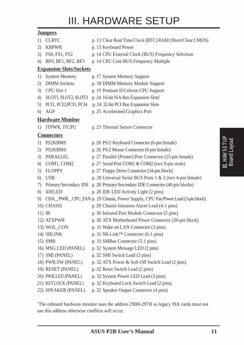
III. HARDWARE SETUPJumpers1) CLRTC p. 13 Clear Real Time Clock (RTC) RAM (Short/Clear CMOS)2) KBPWR p. 13 Keyboard Power3) FS0, FS1, FS2 p. 14 CPU External Clock (BUS) Frequency Selection4) BF0, BF1, BF2, BF3 p. 14 CPU Core:BUS Frequency Multiple
Expansion Slots/Sockets1) System Memory p. 17 System Memory Support2) DIMM Sockets p. 18 DIMM Memory Module Support3) CPU Slot 1 p. 19 Pentium II/Celeron CPU Support4) SLOT1, SLOT2, SLOT3 p. 2416-bit ISA Bus Expansion Slots*
5) PCI1, PCI2,PCI3, PCI4 p. 24 32-bit PCI Bus Expansion Slots6) AGP p. 25 Accelerated Graphics Port
Hardwar e Monitor1) JTPWR, JTCPU p. 23 Thermal Sensor Connector
Connectors1) PS2KBMS p. 26 PS/2 Keyboard Connector (6-pin female)2) PS2KBMS p. 26PS/2 Mouse Connector (6-pin female)3) PARALLEL p. 27 Parallel (Printer) Port Connector (25-pin female)4) COM1, COM2 p. 27Serial Port COM1 & COM2 (two 9-pin male)5) FLOPPY p. 27Floppy Drive Connector (34-pin block)6) USB p. 28 Universal Serial BUS Ports 1 & 2 (two 4-pin female)7) Primary/Secondary IDE p. 28 Primary/Secondary IDE Connector (40-pin blocks)8) IDELED p. 28 IDE LED Activity Light (2 pins)9) CHA_, PWR_, CPU_FAN p. 29 Chassis, Power Supply, CPU Fan Power Lead (3-pin block)10) CHASIS p. 29 Chassis Intrusion Alarm Lead (4-1 pins)
11) IR p. 30 Infrared Port Module Connector (5 pins)12) ATXPWR p. 30 ATX Motherboard Power Connector (20-pin block)13) WOL_CON p. 31 Wake on LAN Connector (3 pins)14) SBLINK p. 31 SB-Link™ Connector (6-1 pins)15) SMB p. 31 SMBus Connector (5-1 pins)16) MSG.LED (PANEL) p. 32 System Message LED (2 pins)17) SMI (PANEL) p. 32 SMI Switch Lead (2 pins)18) PWR.SW (PANEL) p. 32 ATX Power & Soft-Off Switch Lead (2 pins)19) RESET (PANEL) p. 32 Reset Switch Lead (2 pins)20) PWR.LED (PANEL) p. 32 System Power LED Lead (3 pins)21) KEYLOCK (PANEL) p. 32 Keyboard Lock Switch Lead (2 pins)22) SPEAKER (PANEL) p. 32 Speaker Output Connector (4 pins)
*The onboard hardware monitor uses the address 290H-297H so legacy ISA cards must notuse this address otherwise conflicts will occur.
Boar
d La
yout
III. H
/W S
ETU
P
ASUS P2B User’s Manual12
III. HARDWARE SETUP
Jumpers
III. H/W
SETUP
Installation StepsBefore using your computer, you must complete the following steps:
1. Set Jumpers2. Install Memory Modules3. Install the Central Processing Unit (CPU)4. Install Expansion Cards5. Connect Ribbon Cables, Cabinet Wires, and Power Supply6. Setup the BIOS Software
Jumpers
WARNING! Computer motherboards and expansion cards contain very delicateIntegrated Circuit (IC) chips. To protect them against damage from static electric-ity, you should follow some precautions whenever you work on your computer.
1. Unplug your computer when working on the inside.2. Use a grounded wrist strap before handling computer components. If you do
not have one, touch both of your hands to a safely grounded object or to ametal object, such as the power supply case.
3. Hold components by the edges and try not to touch the IC chips, leads orconnectors, or other components.
4. Place components on a grounded antistatic pad or on the bag that came withthe component whenever the components are separated from the system.

ASUS P2B User’s Manual 13
III. HARDWARE SETUP
III. H
/W S
ETU
PJu
mpe
rs
Jumper Settings
1. Clear Real Time Clock (RTC) RAM (CLRTC)The CMOS RAM is powered by the onboard button cell battery. To clear theRTC data: (1) Turn off your computer and unplug your AC power, (2) Short thetwo points labeled CLRTC, (3) Turn on your computer, (4) Hold down<Delete> during bootup and enter BIOS setup to re-enter user preferences.
Short small solder points to clear CMOS
P2B Clear RTC RAM
CLRTC
R
2. Keyboard Power Up (KBPWR)This allows you to disable or enable the keyboard power up function. Set toEnable if you want to use your keyboard (by pressing <Spacebar>) to power upyour computer. This feature requires an ATX power supply that can supply atleast 300mA on the +5VSB lead and the new ACPI BIOS support. The default isset to Disable because not all computers have the appropriate ATX power sup-ply. Your computer will not function if you set this to Enable and if you do nothave the right ATX power supply.
R
Disable
1 2 3KBPWR
Enable
1 2 3
P2B Keyboard Power Up

ASUS P2B User’s Manual14
III. HARDWARE SETUP
Jumpers
III. H/W
SETUP
3. CPU Bus Frequency (FS0, FS1, FS2)This option tells the clock generator what frequency to send to the CPU, DRAM, andAGPset. This allows the selection of the CPU’s External frequency (or BUS Clock).The BUS Clock multiplied by the BUS Ratio equals the CPU’s Internal frequency (theadvertised CPU speed).
4. CPU Core:BUS Frequency Multiple (BF0, BF1, BF2, BF3)This option sets the frequency ratio between the Internal frequency of the CPUand the CPU’s External frequency. These must be set in conjunction with the CPUBus Frequency.
BF
2B
F1
BF
3
CPU Core:BUS Frequency Multiple
P2B CPU
R
BF
0
BF
2B
F1
BF
3
BF
0
BF
2B
F1
BF
3
BF
0
BF
2B
F1
BF
3
BF
0
BF
2B
F1
BF
3
BF
0
BF
2B
F1
BF
3
BF
0
BF
2B
F1
BF
3
BF
0
2.0x (2/1) 2.5x (5/2) 3.0X (3/1) 3.5X (7/2) 4.0X (4/1) 4.5X (9/2) 5.0X (5/1)
FS
1F
S2
FS
0
123
FS
1F
S2
FS
0
123
FS
1F
S2
FS
0
123
21
321
321
321
321
321
3F
S1
FS
2
FS
0
123
FS
1F
S2
FS
0
123
FS
1F
S2
FS
0
103MHz33.4MHz
CPU External Clock (BUS) Frequency Selection
CPUPCI
66.8MHz33.4MHz
75MHz37.5MHz
83.3MHz41.65MHz
100.2MHz33.3MHz
112MHz37.3MHz
BF
2B
F1
BF
3
BF
0
BF
2B
F1
BF
3
BF
0
BF
2B
F1
BF
3
BF
0
BF
2B
F1
BF
3
BF
0
BF
2B
F1
BF
3
BF
0
BF
2B
F1
BF
3
BF
0
5.5x (11/2) 6.0x (6/1) 6.5X (13/2) 7.0X (7/1) 7.5X (15/2) 8.0X (8/1)
21
321
321
321
321
3
123
FS
1F
S2
FS
0
133MHz33.3MHz/44.3MHz
WARNING! Frequencies above 100MHz exceed the specifications for the on-board Intel Chipset and are not guaranteed to be stable.
ASUS P2B User’s Manual 15
III. HARDWARE SETUP
III. H
/W S
ETU
PJu
mpe
rs
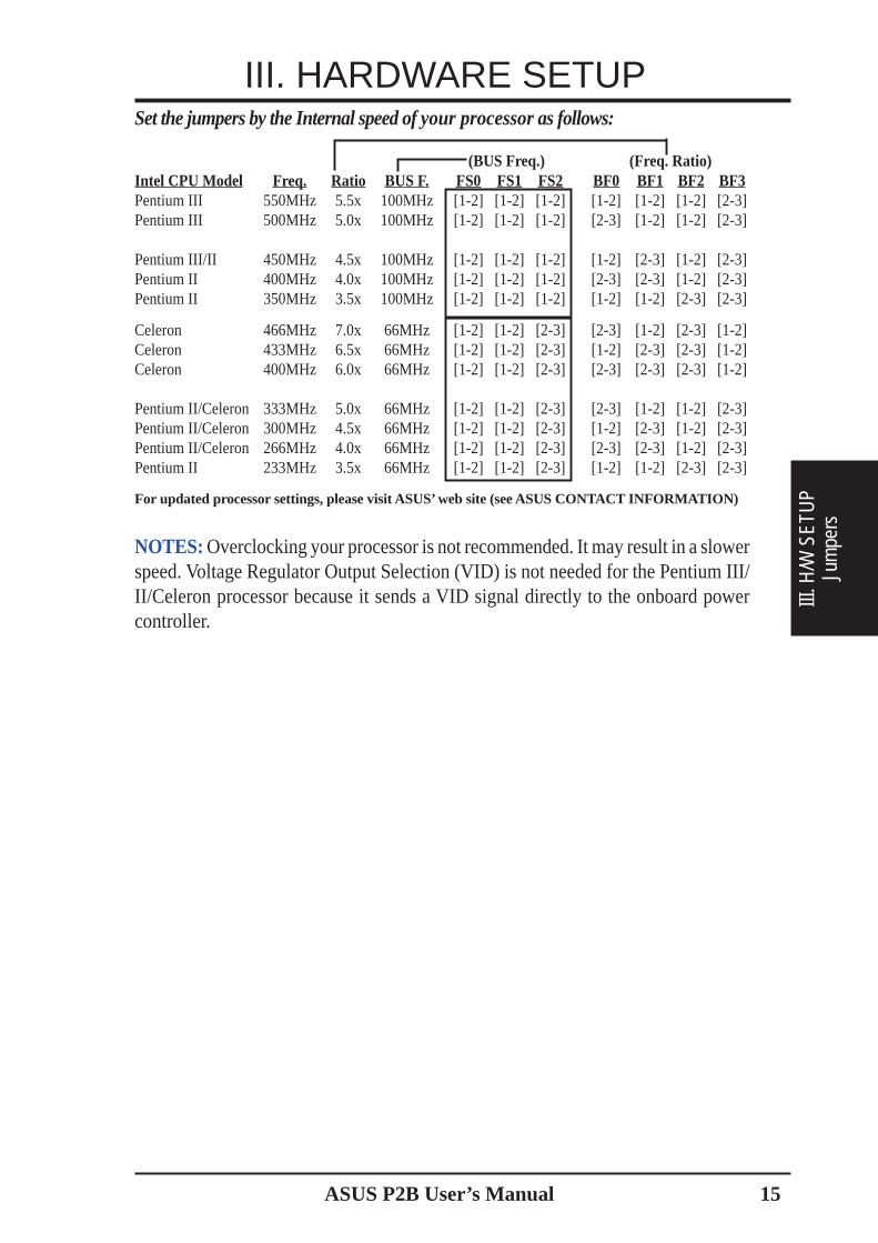
Set the jumpers by the Internal speed of your processor as follows:
(BUS Freq.) (Freq. Ratio)Intel CPU Model Freq. Ratio BUS F. FS0 FS1 FS2 BF0 BF1 BF2 BF3Pentium III 550MHz 5.5x 100MHz [1-2] [1-2] [1-2] [1-2] [1-2] [1-2] [2-3]Pentium III 500MHz 5.0x 100MHz [1-2] [1-2] [1-2] [2-3] [1-2] [1-2] [2-3]
Pentium III/II 450MHz 4.5x 100MHz [1-2] [1-2] [1-2] [1-2] [2-3] [1-2] [2-3]Pentium II 400MHz 4.0x 100MHz [1-2] [1-2] [1-2] [2-3] [2-3] [1-2] [2-3]Pentium II 350MHz 3.5x 100MHz [1-2] [1-2] [1-2] [1-2] [1-2] [2-3] [2-3]
Celeron 466MHz 7.0x 66MHz [1-2] [1-2] [2-3] [2-3] [1-2] [2-3] [1-2]Celeron 433MHz 6.5x 66MHz [1-2] [1-2] [2-3] [1-2] [2-3] [2-3] [1-2]Celeron 400MHz 6.0x 66MHz [1-2] [1-2] [2-3] [2-3] [2-3] [2-3] [1-2]
Pentium II/Celeron 333MHz 5.0x 66MHz [1-2] [1-2] [2-3] [2-3] [1-2] [1-2] [2-3]Pentium II/Celeron 300MHz 4.5x 66MHz [1-2] [1-2] [2-3] [1-2] [2-3] [1-2] [2-3]Pentium II/Celeron 266MHz 4.0x 66MHz [1-2] [1-2] [2-3] [2-3] [2-3] [1-2] [2-3]Pentium II 233MHz 3.5x 66MHz [1-2] [1-2] [2-3] [1-2] [1-2] [2-3] [2-3]
For updated processor settings, please visit ASUS’ web site (see ASUS CONTACT INFORMATION)
NOTES: Overclocking your processor is not recommended. It may result in a slowerspeed. Voltage Regulator Output Selection (VID) is not needed for the Pentium III/II/Celeron processor because it sends a VID signal directly to the onboard powercontroller.

ASUS P2B User’s Manual16
(This page was intentionally left blank.)
III. HARDWARE SETUP
Jumpers
III. H/W
SETUP

ASUS P2B User’s Manual 17
III. H
/W S
ETU
PSy
stem
Mem
ory
Install memory in any combination as follows:
DIMM Location 168-pin DIMM Total Memory
Socket 1 (Rows 0&1) SDRAM 8, 16, 32, 64, 128, 256MB x1
Socket 2 (Rows 2&3) SDRAM 8, 16, 32, 64, 128, 256MB x1
Socket 3 (Rows 4&5) SDRAM 8, 16, 32, 64, 128, 256MB x1
Total System Memory (Max 768MB) =
III. HARDWARE SETUPSystem Memory (DIMM)NOTE: No hardware or BIOS setup is required after adding or removing memory.
This motherboard uses only Dual Inline Memory Modules (DIMMs). Sockets areavailable for 3.3Volt (power level) unbuffered Synchronous Dynamic Random Ac-cess Memory (SDRAM). One side (with memory chips) of the DIMM takes up onerow on the motherboard.
To utilize the chipset’s Error Checking and Correction (ECC) feature, you must use aDIMM module with 9 chips per side (standard 8 chips/side + 1 ECC chip) and makethe proper settings through Chipset Features Setup in BIOS SETUP.
Memory speed setup is recommended through SDRAM Configuration under “ChipsetFeatures Setup” in BIOS SETUP.
NOTE: At the time this User’s Manual was written, 256MB DIMMs are only avail-able as registered memory.
SPD SupportThis motherboard supports SPD DIMMs, and it is recommended that SPD DIMMsbe used.
General DIMM Notes• For the system CPU bus to operate above 100MHz, use only PC100-compli-
ant DIMMs. When this motherboard operates at 100MHz, most system will noteven boot if non-compliant modules are used because of the strict timing issuesinvolved under this speed. If your DIMMs are not PC100-compliant, set theCPU bus frequency (FS) to 66MHz for system stability.
• ASUS motherboards support SPD (Serial Presence Detect) DIMMs. This is thememory of choice for best performance vs. stability.
• SDRAM chips are generally thinner with higher pin density than EDO (Ex-tended Data Output) chips.
• BIOS shows SDRAM memory on bootup screen.• Single-sided DIMMs come in 16, 32, 64,128MB; double-sided come in 32, 64, 128, 256MB.

ASUS P2B User’s Manual18
System M
emory
III. H/W
SETUP
III. HARDWARE SETUPDIMM Memory Installation Procedures:
Insert the module(s) as shown. Because the number of pins are different on eitherside of the breaks, the module will only fit in the orientation as shown. DRAMSIMM modules have the same pin contacts on both sides. SDRAM DIMMs havedifferent pin contacts on each side and therefore have a higher pin density.
Lock
P2B 168-Pin DIMM Memory Sockets
20 Pins 60 Pins 88 PinsR
FRONT
The DIMMs must be 3.3Volt unbuffered SDRAMs. To determine the DIMM type,check the notches on the DIMMs (see figure below).
The notches on the DIMM will shift between left, center, or right to identify the typeand also to prevent the wrong type from being inserted into the DIMM slot on themotherboard. You must tell your retailer the correct DIMM type before purchasing.This motherboard supports four clock signals.
168-Pin DIMM Notch Key Definitions (3.3V)
DRAM Key Position Voltage Key Position
UnbufferedRFUBuffered
Reserved3.3V
5.0V

ASUS P2B User’s Manual 19
III. HARDWARE SETUP
CPU
III. H
/W S
ETUP
Central Processing Unit (CPU)NOTE: The following pictures are provided for reference purposes only. The ap-pearance of your retention mechanism and fan may be different from the followingexamples.
Your motherboard provides a Slot 1 connector for a Pentium® III processor pack-aged in a Single Edge Contact Cartridge (SECC2), a Pentium® II processor pack-aged in SECC/SECC2, or a Celeron™ processor packaged in a Single Edge Proces-sor Package (SEPP). An ASUS S370 CPU card can allow Socket 370 processors tobe used on any ASUS motherboard with the Slot 1 connector (See ASUS S370 CPUCard in APPENDIX for instructions on using this card).
HeatsinksThe recommended heatsinks (see section on recommended heatsinks for PentiumIII / II processors for more information) for the boxed Pentium III / II and Celeronprocessors are those with three-pin fans that can be connected to the fan connectorson the motherboard.
WARNING! Be sure that there is sufficient air circulation across the processor’sheatsink by regularly checking that your CPU fan is working. Without sufficientcirculation, the processor could overheat and damage both the processor and themotherboard. You may install an auxiliary chassis fan, if necessary.
Pentium II processor packaged in an SECC withheatsink and fan (top view)
Pentium III (in an SECC2) with heatsink and fanNOTE: The SEPP fan (for Celeron processors) issimilar to SECC2 fan except that the clampingdesign is different.
Your motherboard comes preinstalledwith a Universal Retention Mechanism(URM). The URM supports Pentium III /II and Celeron processors.
Universal Retention Mechanism (URM)
Universal Retention Mechanism

20 ASUS P2B User’s Manual
III. HARDWARE SETUP
CPU
III. H/W SETUP
2. Attach the Heatsink
NOTE: If provided, you should follow the heatsink attachment instructionsthat came with your heatsink or processor. The following steps are providedonly as a general guide and may not reflect those for your heatsink.
The URM is now ready for the installationof your processor.
Installing the Processor
1. Unlock the URM’s Folding Support Arms:The folding support arms of the URM arelocked when shipped.
Using the SECC fan with the Pentium® IIPush the two lock arms one direction to clampthe heatsink onto the processor and the otherdirection to release.
Using the SECC2 fan with the Pentium® IIIInsert the four heatsink’s pins through theholes of the SECC2. Place the metal clip onthe ends of the pins and slide until it locksinto place.
Unlocked FoldingSupport Arms
Locked FoldingSupport Arms
To unlock the support arms, simply flip themup to an upright position.
Lock Arm Lock Arm
Four Pins and metal clip
NOTE: The SEPP heatsink and fan (for Intel Celeron processors) is similar tothe SECC2 heatsink and fan except that the clamping design is different.
ASUS P2B User’s Manual 21
III. HARDWARE SETUP
CPU
III. H
/W S
ETUP
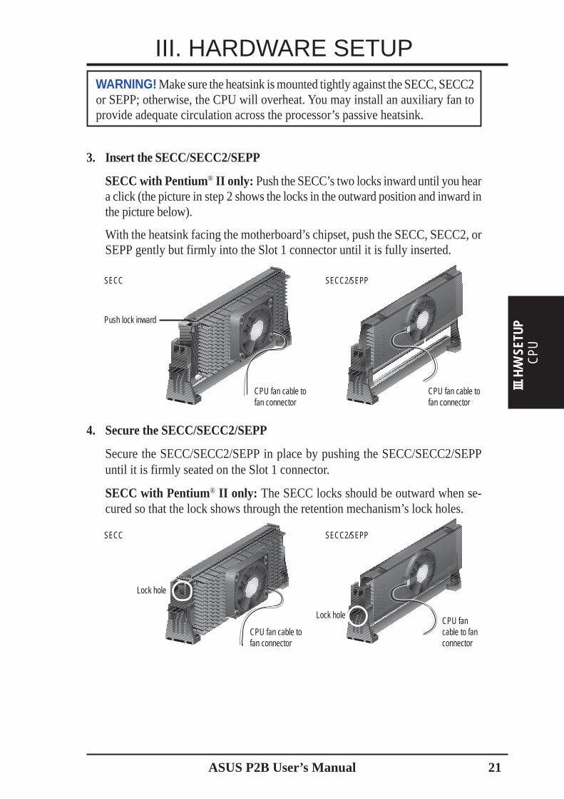
3. Insert the SECC/SECC2/SEPP
SECC with Pentium® II only: Push the SECC’s two locks inward until you heara click (the picture in step 2 shows the locks in the outward position and inward inthe picture below).
With the heatsink facing the motherboard’s chipset, push the SECC, SECC2, orSEPP gently but firmly into the Slot 1 connector until it is fully inserted.
4. Secure the SECC/SECC2/SEPP
Secure the SECC/SECC2/SEPP in place by pushing the SECC/SECC2/SEPPuntil it is firmly seated on the Slot 1 connector.
SECC with Pentium® II only: The SECC locks should be outward when se-cured so that the lock shows through the retention mechanism’s lock holes.
SECC2/SEPP
Push lock inward
SECC
SECC SECC2/SEPP
CPU fan cable tofan connector
CPU fan cable tofan connector
CPU fan cable tofan connector
CPU fancable to fanconnector
Lock hole
WARNING! Make sure the heatsink is mounted tightly against the SECC, SECC2or SEPP; otherwise, the CPU will overheat. You may install an auxiliary fan toprovide adequate circulation across the processor’s passive heatsink.
Lock hole

22 ASUS P2B User’s Manual
III. HARDWARE SETUP
CPU
III. H/W SETUP
ASUS Smart Thermal Solutions
ASUS provides two smart solutions to Slot 1 CPU thermal problems: the ASUSSmart Fan or ASUS S-P2FAN and the ASUS P2T-Cable.
ASUS S-P2FAN
The optional ASUS Smart Fan or ASUS S-P2FAN is aCPU fan for a Pentium® II processor packaged in an SECC.Unlike other CPU thermal solutions, the ASUS S-P2FANhas an integrated thermal sensor located near the centerof the CPU heat source. The sensor is optimized by ASUSto give the most accurate reading of the CPU tempera-ture, thus provides the best protection to your computersystem.
To Use the ASUS S-P2FANSee 2. Attach the Heatsink on the preceding page for the relevant procedures. Notethat the S-P2FAN comes with a rock arm design for easy FAN/CPU installation.ASUS P2T-Cable
The optional ASUS P2T-Cable can beused for a Pentium® III/II processor pack-aged in an SECC2/SECC or a Celeron™processor packaged in an SEPP.
NOTE: The ASUS P2T-Cable can onlybe used in a Slot 1 motherboard with a2-pin thermal sensor connector.
To Use the ASUS P2T-Cable
NOTE: The following procedures assume that you have properly attached aheatsink onto an SECC/SECC2/SEPP.
1. Simply peel off the tab from the sensor and then stick the sensor near the middleedge of the Intel boxed processor heatsink with fan (middle) or to either theupper or lower edge of the Celeron™ heatsink (right), as indicated.
Sensor Connector Plug
Sensor
CPU Fan Cable(3 colored wires)
Thermal Cable(2 black wires)
Tab
Sensor← OR STICK ABOUT HERE

ASUS P2B User’s Manual 23
III. HARDWARE SETUP
CPU
III. H
/W S
ETUP
Recommended Heatsinks for Slot 1 Processors
The recommended heatsinks for the Slot 1 processors are those with three-pin fans,such as the ASUS Smart Fan, that can be connected to the motherboard’s CPU fanconnector. These heatsinks dissipate heat more efficiently and with an optional hard-ware monitor, they can monitor the fan’s RPM and use the alert function with theIntel LANDesk Client Manager (LDCM) or the ASUS PC Probe software.
SECC Heatsink & Fan SECC2 Heatsink & Fan
NOTE: The SEPP heatsink and fan (for Intel Celeron processors) is similar to theSECC2 heatsink and fan except that the clamping design is different.
WARNING! Do not insert the sensor between the processor and heatsink, other-wise, it will cause damage to the P2T-Cable.
IMPORTANT! ASUS guarantees accurate readings only for the ASUS SmartFan and the Intel boxed processor heatsink with fan because both have similarheat distribution and heatsink material.
2. Connect the P2T-Cable to the CPU thermal sensor connector (JTCPU).
P2B-F Thermal Sensor Connectors
R
JTPWR
Power Supply Thermal Sensor Connector
JTCPU
CPU Thermal Sensor Connector
NOTE: If you have a power supply with thermal monitoring, connect its ther-mal sensor cable to JTPWR.
24 ASUS P2B User’s Manual
III. HARDWARE SETUP
Expansion Cards
III. H/W SETUP
Expansion Cards
Expansion Card Installation Procedure1. Read the documentation for your expansion card and make any necessary hard-
ware or software settings for your expansion card, such as jumpers.
2. Remove your computer system’s cover and the bracket plate on the slot youintend to use. Keep the bracket for possible future use.
3. Carefully align the card’s connectors and press firmly.
4. Secure the card on the slot with the screw you removed above.
5. Replace the computer system’s cover.
6. Set up the BIOS if necessary(such as IRQ xx Used By ISA: Yes in PNP AND PCI SETUP)
7. Install the necessary software drivers for your expansion card.
Assigning IRQs for Expansion CardsSome expansion cards need to use an IRQ to operate. Generally, an IRQ must beexclusively assigned to one use. In a standard design, there are 16 IRQs availablebut most of them are already in use, leaving 6 IRQs free for expansion cards. If yourmotherboard has PCI audio onboard, an extra IRQ will be used, leaving 5 IRQsfree. If your motherboard has ISA audio onboard, an extra 3 IRQs will be used,leaving 3 IRQs free.
Both ISA and PCI expansion cards may require to use IRQs. System IRQs are avail-able to cards installed in the ISA expansion bus first, then any remaining IRQs areavailable to PCI cards. Currently, there are two types of ISA cards. The original ISAexpansion card design, now referred to as legacy ISA cards, requires that you con-figure the card’s jumpers manually and then install it in any available slot on the ISAbus. You may use the Microsoft Diagnostics (MSD.EXE) utility located in the Win-dows directory to see a map of your used and free IRQs. If you use Windows 95, theResources tab under Device Manager displays the resource settings being used bya particular device (to gain access, double-click the System icon under the ControlPanel program). Ensure that no two devices share the same IRQs or your computerwill experience problems when those two devices are in use at the same time.
WARNING! Unplug your power supply when adding or removing expansioncards or other system components. Failure to do so may cause severe damage toboth your motherboard and expansion cards.
ASUS P2B User’s Manual 25
III. HARDWARE SETUPTo simplify this process, this motherboard complies with the Plug and Play (PnPspecification, which was developed to allow automatic system configuration when-ever a PnP-compliant card is added to the system. For PnP cards, IRQs are assignedautomatically from those available.
If the system has both legacy and PnP ISA cards installed, IRQs are assigned to PnPcards from those not used by legacy cards. The PCI and PNP configuration sectionof the BIOS setup utility can be used to assign which IRQs are being used by legacycards. For older legacy cards that do not work with the BIOS, you may contact yourvendor for an ISA Configuration Utility.
An IRQ number is automatically assigned to PCI expansion cards after those usedby legacy and PnP ISA cards. In the PCI bus design, the BIOS automatically assignsan IRQ to a PCI slot that contains a card requiring an IRQ. To install a PCI card, youneed to set the INT (interrupt assignment). Since all the PCI slots on this mother-board use an INTA #, set the jumpers on your PCI cards to INT A.
Assigning DMA Channels for ISA CardsSome ISA cards, both legacy and PnP, may also need to use a DMA (Direct MemoryAccess channel. DMA assignments for this motherboard are handled the same wayas the IRQ assignment process described earlier. You can select a DMA channel inthe PCI and PnP configuration section of the BIOS Setup utility.
IMPORTANT: To avoid conflicts, reserve the necessary IRQs and DMAs for legacyISA cards (under PNP AND PCI SETUP of the BIOS SOFTWARE, choose Yes in IRQxx Used By ISA and DMA x Used By ISA for those IRQs and DMAs you want to reserve.
ISA Cards and Hardware MonitorThe onboard hardware monitor uses the address 290H-297H so legacy ISA cardsmust not use this address or else conflicts will occur.
DM
A C
h. /
AGP
Slot
III. H
/W S
ETU
P
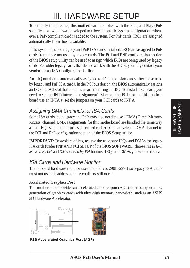
Accelerated Graphics PortThis motherboard provides an accelerated graphics port (AGP) slot to support a newgeneration of graphics cards with ultra-high memory bandwidth, such as an ASUS3D Hardware Accelerator.
P2B Accelerated Graphics Port (AGP)
R

26 ASUS P2B User’s Manual
External Connectors
WARNING! Some pins are used for connectors or power sources. These areclearly distinguished from jumpers in the Motherboard Layout. Placing jumpercaps over these connector pins will cause damage to your motherboard.
IMPORTANT: Ribbon cables should always be connected with the red stripe toPin 1 on the connectors. Pin 1 is usually on the side closest to the power connec-tor on hard drives and CD-ROM drives, but may be on the opposite side onfloppy disk drives. Check the connectors before installation because there maybe exceptions. IDE ribbon cables must be less than 46 cm (18 in.), with thesecond drive connector no more than 15 cm (6 in.) from the first connector.
1. PS/2 Keyboard Connector (6-pin Female)This connection is for a standard keyboard using an PS/2 plug (mini DIN). Thisconnector will not allow standard AT size (large DIN) keyboard plugs. Youmay use a DIN to mini DIN adapter on standard AT keyboards.
PS/2 Keyboard (6-pin Female)
2. PS/2 Mouse Connector (6-pin Female)The system will direct IRQ12 to the PS/2 mouse if one is detected. If not de-tected, expansion cards can use IRQ12. See “PS/2 Mouse Control” in BIOSFeatures Setup of the BIOS SOFTWARE.
PS/2 Mouse (6-pin Female)
Connectors
III. H/W
SETUP
III. HARDWARE SETUP
ASUS P2B User’s Manual 27
III. HARDWARE SETUP
DM
A C
hann
els
III. H
/W S
ETU
P C
onne
ctor
sIII
. H/W
SET
UP
3. Parallel Port Connector (25-pin Female)You can enable the parallel port and choose the IRQ through “Onboard ParallelPort” in Chipset Features Setup of the BIOS SOFTWARE. NOTE: Serial print-ers must be connected to the serial port.
Parallel (Printer) Port (25-pin Female)
4. Serial Port COM1 and COM2 Connectors (Two 9-pin Male)The two serial ports can be used for pointing devices or other serial devices. See“Onboard Serial Port” in Chipset Features Setup of the BIOS SOFTWARE.
COM 1 COM 2Serial Ports (9-pin Male)
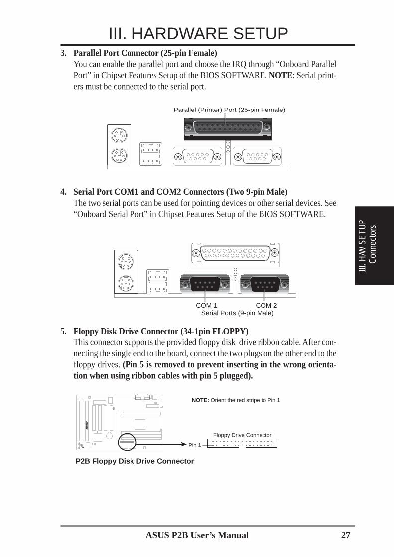
5. Floppy Disk Drive Connector (34-1pin FLOPPY)This connector supports the provided floppy disk drive ribbon cable. After con-necting the single end to the board, connect the two plugs on the other end to thefloppy drives. (Pin 5 is removed to prevent inserting in the wrong orienta-tion when using ribbon cables with pin 5 plugged).
P2B Floppy Disk Drive Connector
NOTE: Orient the red stripe to Pin 1
R
Floppy Drive Connector
Pin 1

28 ASUS P2B User’s Manual
Connectors
III. H/W
SETUP
III. HARDWARE SETUP6. Universal Serial BUS Ports 1 & 2 (Two 4-pin Female)
Two USB ports are available for connecting USB devices.
Universal Serial Bus (USB) 2
USB 1
7. Primary / Secondary IDE Connectors (Two 40-1pin IDE)These connectors support the provided IDE hard disk ribbon cable. After connect-ing the single end to the board, connect the two plugs at the other end to your harddisk(s). If you install two hard disks, you must configure the second drive to Slavemode by setting its jumper accordingly. Refer to the documentation of your harddisk for the jumper settings. BIOS now supports SCSI device or IDE CD-ROMbootup (see “HDD Sequence SCSI/IDE First” & “Boot Sequence” in the BIOSFeatures Setup of the BIOS SOFTWARE) (Pin 20 is removed to prevent in-serting in the wrong orientation when using ribbon cables with pin 20 plugged).TIP: You may configure two hard disks to be both Masters using one ribboncable on the primary IDE connector and another ribbon cable on the secondaryIDE connector. You may install one operating system on an IDE drive and an-other on a SCSI drive and select the boot disk through BIOS Features Setup.
P2B IDE ConnectorsPrimary IDE Connector
PIN 1
Secondary IDE Connector
NOTE: Orient the red stripe to PIN 1
R
8. IDE Device Activity LED (2-pin IDELED)This connector supplies power to the cabinet’s IDE device activity LED. Readand write activity by devices connected to the Primary or Secondary IDE con-nectors will cause the LED to light up.
P2B IDE Activity LED
TIP: If the case-mounted LED does not light, try reversing the 2-pin plug.
IDELED
R

ASUS P2B User’s Manual 29
III. HARDWARE SETUP
Con
nect
ors
III. H
/W S
ETU
P
9. Chassis / CPU / Power Supply Fan Connectors (3-pin FAN)These connectors support cooling fans of 500mA (6 Watts) or less. Orientate thefans so that the heat sink fins allow airflow to go across the onboard heat sink(s)instead of the expansion slots. Depending on the fan manufacturer, the wiring andplug may be different. The red wire should be positive, while the black should beground. Connect the fan’s plug to the board taking into consideration the polarityof the connector. NOTE: The “Rotation” signal is to be used only by a spe-cially designed fan with rotation signal. The Rotations per Minute (RPM)can be monitored using ASUS PC Probe Utility or Intel LDCM Utility.
WARNING! The CPU and/or motherboard will overheat if there is no airflowacross the CPU and onboard heatsinks. Damage may occur to the motherboardand/or the CPU fan if these pins are incorrectly used. These are not jumpers,do not place jumper caps over these pins.
P2B 12Volt Cooling Fan Power
Power Supply FanCPU Fan PowerChassis Fan Power
GN
D
Rot
atio
n+
12VR
10. Chassis Intrusion Alarm Lead (4-1 pin CHASIS)This requires an external detection mechanism such as a chassis intrusion moni-tor/sensor or microswitch. The sensor is triggered when a high level signal issent to the CHASIS lead. This occurs when the side panel is opened or drive baydoors are opened.
NOTE: When the chassis is opened, connect/short the Chassis Signal pin to the+5VSB pin. When the chassis is opened, connect/short the Chassis Signal pin tothe Ground pin.
R
P2B Chassis Intrusion Alarm Lead
+5VSBChassis Signal
Ground
30 ASUS P2B User’s Manual
III. HARDWARE SETUP
Connectors
III. H/W
SETUP
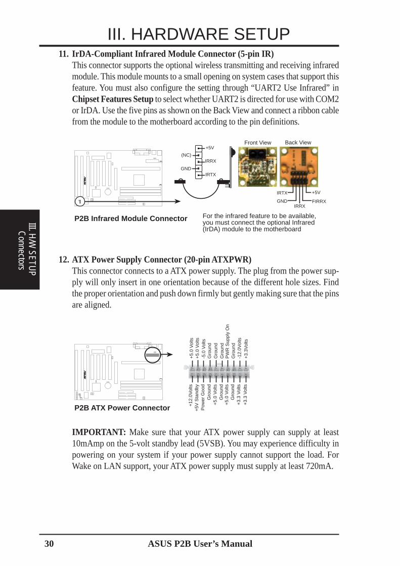
11. IrDA-Compliant Infrared Module Connector (5-pin IR)This connector supports the optional wireless transmitting and receiving infraredmodule. This module mounts to a small opening on system cases that support thisfeature. You must also configure the setting through “UART2 Use Infrared” inChipset Features Setup to select whether UART2 is directed for use with COM2or IrDA. Use the five pins as shown on the Back View and connect a ribbon cablefrom the module to the motherboard according to the pin definitions.
Front View
+5VIRTX
IRRXFIRRXGND
Back View
P2B Infrared Module Connector For the infrared feature to be available,you must connect the optional Infrared(IrDA) module to the motherboard
+5V
IRRX
IRTX
(NC)
GND
R
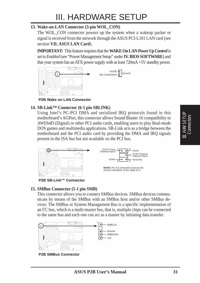
12. ATX Power Supply Connector (20-pin ATXPWR)This connector connects to a ATX power supply. The plug from the power sup-ply will only insert in one orientation because of the different hole sizes. Findthe proper orientation and push down firmly but gently making sure that the pinsare aligned.
P2B ATX Power Connector
R
+3.
3Vol
ts-1
2.0V
olts
Gro
und
PW
R S
uppl
y O
nG
roun
dG
roun
dG
roun
d-5
.0 V
olts
+5.
0 V
olts
+5.
0 V
olts
Pow
er G
ood
+12
.0V
olts
+3.
3 V
olts
+3.
3 V
olts
Gro
und
+5.
0 V
olts
Gro
und
+5.
0 V
olts
Gro
und
+5V
Sta
ndby
IMPORTANT: Make sure that your ATX power supply can supply at least10mAmp on the 5-volt standby lead (5VSB). You may experience difficulty inpowering on your system if your power supply cannot support the load. ForWake on LAN support, your ATX power supply must supply at least 720mA.
ASUS P2B User’s Manual 31
III. HARDWARE SETUP
Con
nect
ors
III. H
/W S
ETU
P
13. Wake-on-LAN Connector (3-pin WOL_CON)The WOL_CON connector powers up the system when a wakeup packet orsignal is received from the network through the ASUS PCI-L101 LAN card (seesection VII. ASUS LAN Card ).
IMPORTANT: This feature requires that the WAKE On LAN Power Up Control isset to Enabled (see “Power Management Setup” under IV. BIOS SOFTWARE ) andthat your system has an ATX power supply with at least 720mA +5V standby power.
P2B Wake on LAN Connector
+5VSB(No Connection)
Ground
R
14. SB-Link™ Connector (6-1 pin SBLINK)Using Intel’s PC-PCI DMA and serialized IRQ protocols found in thismotherboard’s AGPset, this connector allows Sound Blaster 16 compatibility toAWE64D (Digital) or other PCI audio cards, enabling users to play Real-modeDOS games and multimedia applications. SB-Link acts as a bridge between themotherboard and the PCI audio card by providing the DMA and IRQ signalspresent in the ISA bus but not available on the PCI bus.
R
P2B SB-Link™ Connector
PC/PCI GrantSideband Signal
5 6
PC/PCI RequestSideband Signal
1DGND
2
DGND Serial IRQ
NOTE: Pin 3 is removed to ensure thecorrect orientation of the cable on it.
4
15. SMBus Connector (5-1 pin SMB)This connector allows you to connect SMBus devices. SMBus devices commu-nicate by means of the SMBus with an SMBus host and/or other SMBus de-vices. The SMBus or System Management Bus is a specific implementation ofan I2C bus, which is a multi-master bus, that is, multiple chips can be connectedto the same bus and each one can act as a master by initiating data transfer.
P2B SMBus Connector
R
SMBCLK
GroundSMBDATA
+5V
1

32 ASUS P2B User’s Manual
III. HARDWARE SETUP
Connectors
III. H/W
SETUP
16. Message LED Lead (MSG.LED)This indicates whether a message has been received from a fax/modem. TheLED will remain lit when there is no signal and blink when there is data transferor waiting in the inbox. This function requires ACPI OS and driver support.
17. SMI Suspend Switch Lead (SMI)This allows the user to manually place the system into a suspend mode or “Green”mode where system activity will be instantly decreased to save electricity andexpand the life of certain components when the system is not in use. This 2-pinconnector (see the figure below) connects to the case-mounted suspend switch.If you do not have a switch for the connector, you may use the “Turbo Switch”since it does not have a function. SMI is activated when it detects a short to openmoment and therefore leaving it shorted will not cause any problems. This mayrequire one or two pushes depending on the position of the switch.
18. ATX Power Switch / Soft Power Switch (PWR.SW)The system power is controlled by a momentary switch connected to this lead.Pushing the button once will switch the system between ON and SLEEP. Push-ing the switch while in the ON mode for more than 4 seconds will turn thesystem off. The system power LED shows the status of the system’s power.
19. Reset Switch Lead (RESET)This 2-pin connector connects to the case-mounted reset switch for rebootingyour computer without having to turn off your power switch. This is a preferredmethod of rebooting to prolong the life of the system’s power supply.
20. System Power LED (PWR LED)This 3-pin connector connects the system power LED, which lights when thesystem is powered on and blinks when it is in sleep mode.
21. Keyboard Lock Switch Lead (KEYLOCK)This 2-pin connector connects to the case-mounted key switch to allow key-board locking.
22. Speaker Connector (SPEAKER)This 4-pin connector connects to the case-mounted speaker.
P2B System Panel Connections
PLED
Ground
MLED
PWR_SW
* Requires an ATX power supply.
+5 V
KEYLOCK
+5V
SPKR
Keyboard Lock
SpeakerConnector
Power LED
Ground
+5 V
Reset SW
SMI Lead
MessageLED
ATX PowerSwitch*
ExtSMI#
+3VSB
ResetConGroundGround
Ground
R
ASUS P2B User’s Manual 33
III. HARDWARE SETUP
Pow
er C
onne
ctio
nsIII
. H/W
SET
UP
Power Connection Procedures1. After all connections are made, close the system case cover.
2. Be sure that all switches are off (in some systems, marked with ).
3. Connect the power supply cord into the power supply located on the back ofyour system case according to your system user’s manual.
4. Connect the power cord into a power outlet that is equipped with a surge protector.
5. You may then turn on your devices in the following order:a. Your monitorb. External SCSI devices (starting with the last device on the chain)c. Your system power. For ATX power supplies, you need to switch on the power
supply as well as press the ATX power switch on the front of the case.
6. The power LED on the front panel of the system case will light. For ATX powersupplies, the system LED will light when the ATX power switch is pressed. TheLED on the monitor may light up or switch between orange and green after thesystem’s if it complies with “green” standards or if it has a power standby feature.The system will then run power-on tests. While the tests are running, additionalmessages will appear on the screen. If you do not see anything within 30 secondsfrom the time you turn on the power, the system may have failed a power-on test.Recheck your jumper settings and connections or call your retailer for assistance.
7. During power-on, hold down <Delete> to enter BIOS setup. Follow the instruc-tions in BIOS SETUP.
* Powering Off your computer: You must first exit or shut down your operatingsystem before switching off the power switch. For ATX power supplies, you canpress the ATX power switch after exiting or shutting down your operating system.If you use Windows 95, click the Start button, click Shut Down, and then clickShut down the computer? The power supply should turn off after Windowsshuts down.
NOTE: The message “You can now safely turn off your computer” will not ap-pear when shutting down with ATX power supplies.
34 ASUS P2B User’s Manual
Managing and Updating Your BIOSUpon First Use of the Computer System
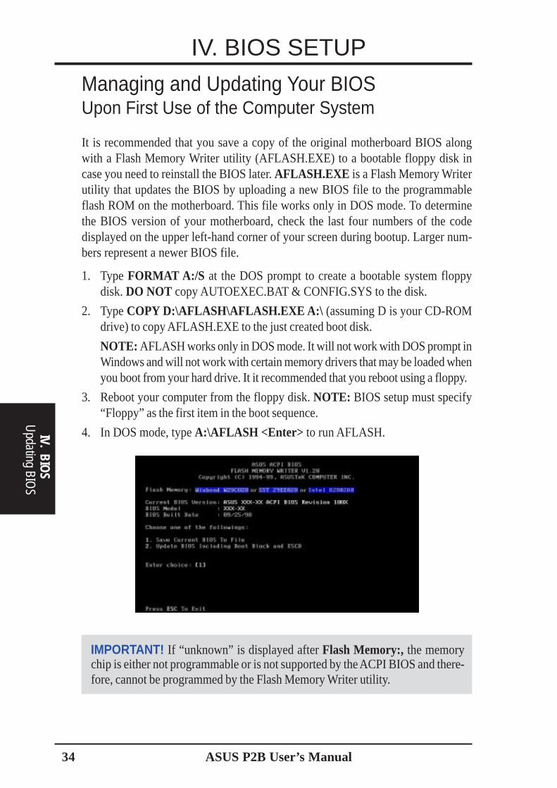
It is recommended that you save a copy of the original motherboard BIOS alongwith a Flash Memory Writer utility (AFLASH.EXE) to a bootable floppy disk incase you need to reinstall the BIOS later. AFLASH.EXE is a Flash Memory Writerutility that updates the BIOS by uploading a new BIOS file to the programmableflash ROM on the motherboard. This file works only in DOS mode. To determinethe BIOS version of your motherboard, check the last four numbers of the codedisplayed on the upper left-hand corner of your screen during bootup. Larger num-bers represent a newer BIOS file.
1. Type FORMAT A:/S at the DOS prompt to create a bootable system floppydisk. DO NOT copy AUTOEXEC.BAT & CONFIG.SYS to the disk.
2. Type COPY D:\AFLASH\AFLASH.EXE A:\ (assuming D is your CD-ROMdrive) to copy AFLASH.EXE to the just created boot disk.
NOTE: AFLASH works only in DOS mode. It will not work with DOS prompt inWindows and will not work with certain memory drivers that may be loaded whenyou boot from your hard drive. It it recommended that you reboot using a floppy.
3. Reboot your computer from the floppy disk. NOTE: BIOS setup must specify“Floppy” as the first item in the boot sequence.
4. In DOS mode, type A:\AFLASH <Enter> to run AFLASH.
IMPORTANT! If “unknown” is displayed after Flash Memory:, the memorychip is either not programmable or is not supported by the ACPI BIOS and there-fore, cannot be programmed by the Flash Memory Writer utility.
IV. BIOS SETUP
IV. BIOS
Updating BIO
S

ASUS P2B User’s Manual 35
5. Select 1. Save Current BIOS to File from the Main menu and press <Enter>.The Save Current BIOS To File screen appears.
6. Type a filename and the path, for example, A:\XXX-XX.XXX and then press <Enter>.
Updating BIOS ProceduresWARNING! Only update your BIOS if you have problems with your mother-board and you know that the new BIOS revision will solve your problems. Care-less updating can result in your motherboard having more problems!
1. Download an updated ASUS BIOS file from the Internet (WWW or FTP) (seeASUS CONTACT INFORMATION on page 3 for details) and save to the diskyou created earlier.
2. Boot from the disk you created earlier.3. At the “A:\” prompt, type AFLASH and then press <Enter>.4. At the Main Menu, type 2 and then press <Enter>. The Update BIOS Includ-
ing Boot Block and ESCD screen appears.5. Type the filename of your new BIOS and the path, for example, A:\XXX-
XX.XXX , and then press <Enter>.NOTE: To cancel this operation, press <Enter>.
IV. BIOS SETUP
IV.
BIO
S U
pdat
ing
BIO
S

36 ASUS P2B User’s Manual
IV. BIOS
Updating BIO
S
IV. BIOS SETUP6. When prompted to confirm the BIOS update, press Y to start the update.
7. The utility starts to program the new BIOS information into the flash ROM. Theboot block will be updated automatically only when necessary. This will mini-mize the chance that a failed update will prevent your system from booting up.When the programming is finished, Flashed Successfully will be displayed.
8. Follow the onscreen instructions to continue.
WARNING! If you encounter problems while updating the new BIOS, DO NOTturn off your system since this might prevent your system from booting up. Justrepeat the process, and if the problem still persists, update the original BIOS fileyou saved to disk above. If the Flash Memory Writer utility was not able to suc-cessfully update a complete BIOS file, your system may not be able to boot up. Ifthis happens, your system will need servicing.
ASUS P2B User’s Manual 37
IV. BIOS SETUPBIOS Setup
IV.
BIO
S U
pdat
ing
BIO
S
The motherboard supports a 5 Volt programmable Flash ROM chip, which can beupdated when BIOS upgrades are released. Use the Flash Memory Writer utility todownload the new BIOS file into the ROM chip as described in detail in this section.
All computer motherboards provide a Setup utility program for specifying the systemconfiguration and settings. If your motherboard came in a computer system, the properconfiguration entries may have already been made. If so, invoke the Setup utility, asdescribed later, and take note of the configuration settings for future reference; inparticular, the hard disk specifications.
If you are installing the motherboard, reconfiguring your system or you receive a RunSetup message, you will need to enter new setup information. This section describeshow to configure your system using this utility.
The BIOS ROM of the system stores the Setup utility. When you turn on the com-puter, the system provides you with the opportunity to run this program. This appearsduring the Power-On Self Test (POST). Press <Delete> to call up the Setup utility. Ifyou are a little bit late pressing the mentioned key(s), POST will continue with its testroutines, thus preventing you from calling up Setup. If you still need to call Setup,reset the system by pressing <Ctrl> + <Alt> + <Delete>, or by pressing the Resetbutton on the system case. You can also restart by turning the system off and thenback on again. But do so only if the first two methods fail.
When you invoke Setup, the CMOS SETUP UTILITY main program screen willappear with the following options:
38 ASUS P2B User’s Manual
IV. BIOS SETUP
IV. BIOS
Standard CM
OS
Load DefaultsThe “Load BIOS Defaults” option loads the minimum settings for troubleshooting.“Load Setup Defaults”, on the other hand, is for loading optimized defaults forregular use. Choosing defaults at this level, will modify all applicable settings.
A section at the bottom of the above screen displays the control keys for this screen.Take note of these keys and their respective uses. Another section just below the controlkeys section displays information on the currently highlighted item in the list.
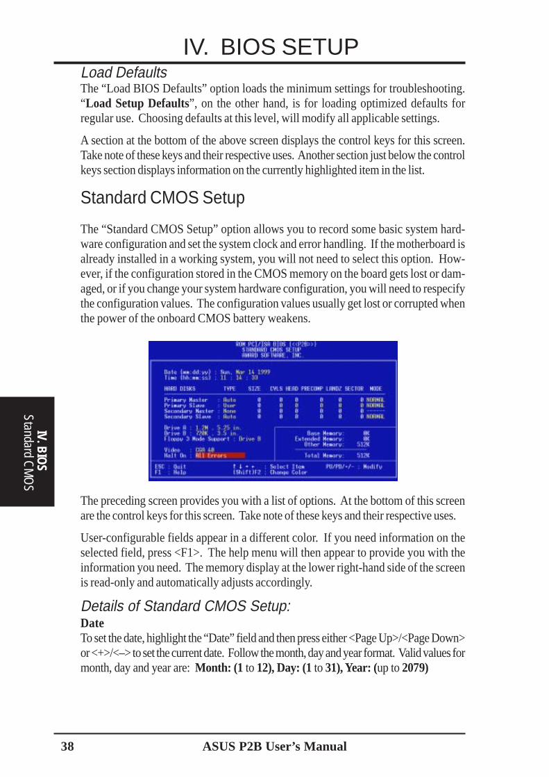
Standard CMOS Setup
The “Standard CMOS Setup” option allows you to record some basic system hard-ware configuration and set the system clock and error handling. If the motherboard isalready installed in a working system, you will not need to select this option. How-ever, if the configuration stored in the CMOS memory on the board gets lost or dam-aged, or if you change your system hardware configuration, you will need to respecifythe configuration values. The configuration values usually get lost or corrupted whenthe power of the onboard CMOS battery weakens.
The preceding screen provides you with a list of options. At the bottom of this screenare the control keys for this screen. Take note of these keys and their respective uses.
User-configurable fields appear in a different color. If you need information on theselected field, press <F1>. The help menu will then appear to provide you with theinformation you need. The memory display at the lower right-hand side of the screenis read-only and automatically adjusts accordingly.
Details of Standard CMOS Setup:DateTo set the date, highlight the “Date” field and then press either <Page Up>/<Page Down>or <+>/<–> to set the current date. Follow the month, day and year format. Valid values formonth, day and year are: Month: (1 to 12), Day: (1 to 31), Year: (up to 2079)

ASUS P2B User’s Manual 39
IV. BIOS SETUP
IV. B
IOS
Sta
ndar
d C
MO
S
TimeTo set the time, highlight the “Time” field and then press either <Page Up>/<Page Down> or<+>/<–> to set the current time. Follow the hour, minute and second format. Valid values forhour, minute and second are: (Hour: (00 to 23), Minute: (00 to 59), Second: (00 to 59).
NOTE: You can bypass the date and time prompts by creating an AUTOEXEC.BATfile. For information on how to create this file, please refer to the MS-DOS manual.
Hard DisksThis field records the specifications for all non-SCSI hard disk drives installed in yoursystem. The onboard PCI IDE connectors provide Primary and Secondary channelsfor connecting up to four IDE hard disks or other IDE devices. Each channel cansupport up to two hard disks; the first of which is the “master” and the second is the“slave”.
Specifications for SCSI hard disks need not to be entered here since they operateusing device drivers and are not supported by the motherboard BIOS software. If themotherboard has SCSI onboard, see the SCSI section for information on configuringSCSI devices. If you are using SCSI controller cards, refer to their respective docu-mentations on how to configure and setup SCSI devices.
For IDE hard disk drive setup, you can:• Use the Auto setting for detection during bootup.• Use the IDE HDD AUTO DETECTION in the main menu to automatically
enter the drive specifications.• Enter the specifications yourself manually by using the “User” option.
The entries for specifying the hard disk type include CYLS (number of cylinders),HEAD (number of read/write heads), PRECOMP (write precompensation), LANDZ(landing zone), SECTOR (number of sectors) and MODE . The SIZE field auto-matically adjusts according to the configuration you specify. The documentation thatcomes with your hard disk should provide you with the information regarding thedrive specifications.
The MODE entry is for IDE hard disks only, and can be ignored for MFM and ESDIdrives. This entry provides three options: Normal, Large, LBA, or Auto (see below).Set MODE to the Normal for IDE hard disk drives smaller than 528MB; set it to LBAfor drives over 528MB that support Logical Block Addressing (LBA) to allow largerIDE hard disks; set it to Large for drives over 528MB that do not support LBA. Largetype of drive can only be used with MS-DOS and is very uncommon. Most IDEdrives over 528MB support the LBA mode.
40 ASUS P2B User’s Manual
IV. BIOS SETUP
IV. BIOS
Standard CM
OS
Auto detection of hard disks on bootupFor each field: Primary Master, Primary Slave, Secondary Master, and SecondarySlave, you can select Auto under the TYPE and MODE fields. This will enable autodetection of your IDE hard disk during bootup. This will allow you to change yourhard disks (with the power off) and then power on without having to reconfigure yourhard disk type. If you use older hard disks that do not support this feature, then youmust configure the hard disk in the standard method as described earlier by the “User”option.
NOTE: After the IDE hard disk drive information has been entered into BIOS, newIDE hard disk drives must be partitioned (such as with FDISK) and then formattedbefore data can be read from and write on. Primary IDE hard disk drives must have itspartition set to active (also possible with FDISK).
NOTE: SETUP Defaults are noted in parenthesis next to each function heading.
Drive A / Drive BThese fields record the types of floppy disk drives installed in your system. Theavailable options for drives A and B are: 360K, 5.25 in.; 1.2M, 5.25 in.; 720K, 3.5 in.;1.44M, 3.5 in.; 2.88M, 3.5 in.; None
To enter the configuration value for a particular drive, highlight its correspondingfield and then select the drive type using the <Page Up>/<Page Down> or <+>/<->keys.
Floppy 3 Mode SupportThis is the Japanese standard floppy drive. The standard stores 1.2MB in a 3.5inchdiskette. This is normally disabled but you may choose from either: Drive A, Drive B,Both, and Disabled.
VideoSet this field to the type of video display card installed in your system. The optionsare EGA/VGA, CGA 40, CGA 80, and MONO (for Hercules or MDA).
If you are using a VGA or any higher resolution card, choose EGA/VGA.
Halt OnThis field determines which types of errors will cause the system to halt. Choose fromAll Errors; No Errors; All, But Keyboard, All, But Diskette; and All, But Disk/Key.
ASUS P2B User’s Manual 41
IV. BIOS SETUP
IV. B
IOS
BIO
S Fe
atur
es
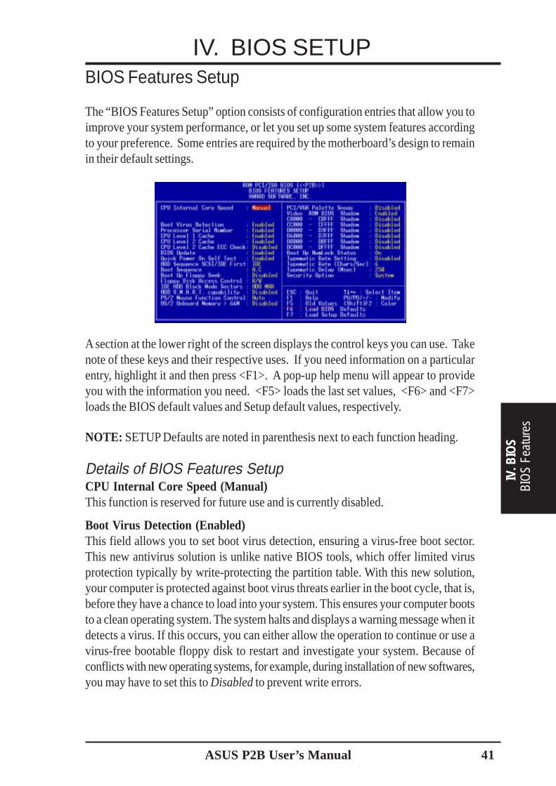
BIOS Features Setup
The “BIOS Features Setup” option consists of configuration entries that allow you toimprove your system performance, or let you set up some system features accordingto your preference. Some entries are required by the motherboard’s design to remainin their default settings.
A section at the lower right of the screen displays the control keys you can use. Takenote of these keys and their respective uses. If you need information on a particularentry, highlight it and then press <F1>. A pop-up help menu will appear to provideyou with the information you need. <F5> loads the last set values, <F6> and <F7>loads the BIOS default values and Setup default values, respectively.
NOTE: SETUP Defaults are noted in parenthesis next to each function heading.
Details of BIOS Features SetupCPU Internal Core Speed (Manual)This function is reserved for future use and is currently disabled.
Boot Virus Detection (Enabled)This field allows you to set boot virus detection, ensuring a virus-free boot sector.This new antivirus solution is unlike native BIOS tools, which offer limited virusprotection typically by write-protecting the partition table. With this new solution,your computer is protected against boot virus threats earlier in the boot cycle, that is,before they have a chance to load into your system. This ensures your computer bootsto a clean operating system. The system halts and displays a warning message when itdetects a virus. If this occurs, you can either allow the operation to continue or use avirus-free bootable floppy disk to restart and investigate your system. Because ofconflicts with new operating systems, for example, during installation of new softwares,you may have to set this to Disabled to prevent write errors.

42 ASUS P2B User’s Manual
IV. BIOS SETUP
IV. BIOS
BIOS Features
Processor Serial Number (Enabled)The Processor Serial Number is a unique electronic number that is added to everyPentium III processor to help verify the identity of the user across the Internet. Set thisfield to Enabled when you need increased security for doing business online (e-com-merce). Otherwise, set it to Disabled for greater anonymity when surfing the Internet.
CPU Level 1 Cache / CPU Level 2 Cache (Enabled)These fields allow you to choose from the default of Enabled or choose Disabled toturn on or off the CPU’s Level 1 and Level 2 built-in cache.
CPU Level 2 Cache ECC Check (Disabled)This function controls the ECC check capability in the CPU level 2 cache.
BIOS Update (Enabled)This functions as an update loader integrated into the BIOS to supply the processorwith the required data. The BIOS will load the update on all processors during systembootup in the default position of Enabled.
Turbo Mode (Disabled)Leave on default setting for best performance.
Quick Power On Self Test (Enabled)This field speeds up the Power-On Self Test (POST) routine by skipping retesting asecond, third, and forth time. Setup default setting for this field is Enabled. A com-plete test of the system is done on each test.
HDD Sequence SCSI/IDE First (IDE)When using both SCSI and IDE hard disk drives, IDE is always the boot disk usingdrive letter C (default setting of IDE ). This new feature allows a SCSI hard disk driveto be the boot disk when set to SCSI. This allows multiple operating systems to beused on both IDE and SCSI drives or the primary operating system to boot using aSCSI hard disk drive.
Boot Sequence (A,C)This field determines where the system looks first for an operating system. Optionsare A, C; C, A; A, CDROM, C; CDROM, C, A; CDROM, A, C; D, A; E, A; F, A; C only;LS/ZIP, C; LAN, A, C; and LAN, C, A. The setup default setting is to check first thefloppy disk and then the hard disk drive, that is, A, C.
Boot Up Floppy Seek (Disabled)When enabled, the BIOS will seek drive A once.
Floppy Disk Access Control (R/W)This allows protection of files from the computer system to be copied to floppy disksby allowing the setting of Read Only to only allow reads from the floppy disk drivebut not writes. The setup default R/W allows both reads and writes.
IDE HDD Block Mode Sectors (HDD MAX)This field enhances hard disk performance by making multi-sector transfers insteadof one sector per transfer. Most IDE drives, except older versions, can utilize thisfeature. Selections are HDD MAX, Disabled, 2, 4, 8, 16, and 32.
ASUS P2B User’s Manual 43
IV. BIOS SETUP
IV. B
IOS
BIO
S Fe
atur
es
HDD S.M.A.R.T. capability (Disabled)This allows the enabling or disabling of the S.M.A.R.T. (Self-Monitoring, Analysisand Reporting Technology) system which utilizes internal hard disk drive monitoringtechnology. This feature is normally disabled because system resources used in thisfeature may decrease system performance.PS/2 Mouse Function Control (Auto)The default of Auto allows the system to detect a PS/2 mouse on bootup. If detected,IRQ12 will be used for the PS/2 mouse. IRQ12 will be reserved for expansion cardsif a PS/2 mouse is not detected. Enabled will always reserve IRQ12, whether onbootup a PS/2 mouse is detected or not.OS/2 Onboard Memory > 64M (Disabled)When using OS/2 operating systems with installed DRAM of greater than 64MB,you need to set this option to Enabled otherwise leave this on Disabled.......................................................................................................................................PCI/VGA Palette Snoop (Disabled)Some display cards that are nonstandard VGA such as graphics accelerators or MPEGVideo Cards may not show colors properly. The setting Enabled should correct thisproblem. Otherwise leave this on the setup default setting of Disabled.Video ROM BIOS Shadow (Enabled)This field allows you to change the video BIOS location from ROM to RAM. Relo-cating to RAM enhances system performance, as information access is faster than theROM.C8000-CBFFF to DC000-DFFFF (Disabled)These fields are used for shadowing other expansion card ROMs. If you install otherexpansion cards with ROMs on them, you will need to know which addresses theROMs use to shadow them specifically. Shadowing a ROM reduces the memoryavailable between 640K and 1024K by the amount used for this purpose.Boot Up NumLock Status (On)This field enables users to activate the Number Lock function upon system boot.Typematic Rate Setting (Disabled)When enabled, you can set the two typematic controls listed next. Setup default set-ting is Disabled.Typematic Rate (Chars/Sec) (6)This field controls the speed at which the system registers repeated keystrokes. Op-tions range from 6 to 30 characters per second. Setup default setting is 6; othersettings are 8, 10, 12, 15, 20, 24, and 30.Typematic Delay (Msec) (250)This field sets the time interval for displaying the first and second characters. Fourdelay rate options are available: 250, 500, 750, and 1000.Security Option (System)When you specify a Supervisor Password and/or User Password (explained later inthis section), the Security Option field determines when the system prompts for thepassword. The default setting is System, where the system prompts for the User Pass-word every time you start your system. The other option is Setup, where the systemgoes through its startup routine unless the Setup utility is called, when the systemprompts for the Supervisor Password.
44 ASUS P2B User’s Manual
IV. BIOS SETUP
IV. BIOS
Chipset Features
Chipset Features Setup
The “Chipset Features Setup” option controls the configuration of the board’s chipset.Control keys for this screen are the same as for the previous screen.
NOTE: SETUP Defaults are noted in parenthesis next to each function heading.
Details of Chipset Features SetupSDRAM Configuration (By SPD)This sets the optimal timings for items 2-5. Leave on default setting.
SDRAM CAS LatencyThis controls the latency between SDRAM read command and the time that the dataactually becomes available. Leave on default setting.
SDRAM RAS to CAS DelayThis controls the latency between SDRAM active command and the read/write com-mand. Leave on default setting.
SDRAM RAS Precharge TimeThis controls the idle clocks after issuing a precharge command to SDRAM. Leaveon default setting.
DRAM Idle TimerThis controls the idle clocks before closing an opened SDRAM page. Leave on de-fault setting.
SDRAM MA Wait State (Normal)This controls the leadoff clocks for CPU read cycles. Leave on default setting.
Snoop Ahead (Enabled)Enabled will allow PCI streaming. Leave on default setting.
Host Bus Fast Data Ready (Disabled)Leave on default setting.
16-bit I/O Recovery Time (1 BUSCLK) / 8-bit I/O Recovery Time (1 BUSCLK)Timing for 16-bit and 8-bit ISA cards, respectively. Leave on default setting.
ASUS P2B User’s Manual 45
IV. BIOS SETUP
IV. B
IOS
Chi
pset
Fea
ture
s
Graphics Aperture Size (64MB)Memory-mapped, graphics data structures can reside in a Graphics Aperture. Leaveon default setting.
Video Memory Cache Mode (UC)USWC (uncacheable, speculative write combining) is a new cache technology for thevideo memory of the processor. It can greatly improve the display speed by cachingthe display data. You must leave this on the default setting of UC (uncacheable) ifyour display card cannot support this feature or else your system may not boot.
PCI 2.1 Support (Enabled)This function allows you to enable or disable PCI 2.1 features including passive release anddelayed transaction. Leave Enabled (default setting) for PCI 2.1 compliancy.
Memory Hole At 15M–16M (Disabled)Enabling this feature reserves 15MB to 16MB memory address space to ISA expan-sion cards that specifically require this setting. This makes the memory from 15MBand up unavailable to the system. Expansion cards can only access memory up to16MB. The default is Disabled.
DRAM are xx bits wideIf all your DIMMs have ECC (e.g., 8 chips + 1 ECC chip), they are considered 72bitsand the following will be displayed:
If your DIMMs do not have ECC (e.g. 8 chips), they are considered 64 bits and thefollowing will be displayed instead:
Data Integrity Mode (Non-ECC)Non-ECC has byte-wise write capability but no provision for protecting data integrity inthe DRAM array. EC-Only data errors are detected but not corrected. ECC with hardwarescrubbing allows a detection of single-bit and multiple-bit errors and recovery of single-biterrors. (See section III for more information on DRAM memory modules.)
....................................................................................................................................
Onboard FDC Controller (Enabled)When Enabled, this field allows you to connect your floppy disk drives to the onboardfloppy disk drive connector instead of a separate controller card. If you want to use adifferent controller card to connect the floppy disk drives, set this field to Disabled.

46 ASUS P2B User’s Manual
IV. BIOS SETUPOnboard FDC Swap A & B (No Swap)This field allows you to reverse the hardware drive letter assignments of your floppy diskdrives. Two options are available: No Swap and Swap AB. If you want to switch drive letterassignments through the onboard chipset, set this field to Swap AB.
Onboard Serial Port 1 (3F8H/IRQ4)Settings are 3F8H/IRQ4, 2F8H/IRQ3, 3E8H/IRQ4, 2E8H/IRQ10, and Disabled forthe onboard serial connector.
Onboard Serial Port 2 (2F8H/IRQ3)Settings are 3F8H/IRQ4, 2F8H/IRQ3, 3E8H/IRQ4, 2E8H/IRQ10, and Disabled forthe onboard serial connector.
Onboard Parallel Port (378H/IRQ7)This field sets the address of the onboard parallel port connector. You can select either:3BCH / IRQ 7, 378H / IRQ 7, 278H / IRQ 5, Disabled. If you install an I/O card with aparallel port, ensure that there is no conflict in the address assignments. The PC cansupport up to three parallel ports as long as there are no conflicts for each port.
Parallel Port Mode (ECP+EPP)This field allows you to set the operation mode of the parallel port. The setting Nor-mal, allows normal-speed operation but in one direction only; EPP allows bidirec-tional parallel port operation at maximum speed; ECP allows the parallel port to oper-ate in bidirectional mode and at a speed faster than the maximum unidirectional datatransfer rate; ECP+EPP allows normal speed operation in a two-way mode.
ECP DMA Select (3)This selection is available only if you select ECP or ECP+EPP in the Parallel PortMode. Select either DMA Channel 1, 3, or Disable.
UART2 Use Infrared (Disabled)When enabled, this field activates the onboard infrared feature and sets the second serialUART to support the infrared module connector on the motherboard. If your systemalready has a second serial port connected to the onboard COM2 connector, it will nolonger work if you enable the infrared feature. By default, this field is set to Disabled,which leaves the second serial port UART to support the COM2 serial port connector.See IrDA-compliant infrared module connector under section III.
Onboard PCI IDE Enable (Both)You can select to enable the primary IDE channel, secondary IDE channel, both, ordisable both channels (for systems with only SCSI drives).
IDE Ultra DMA Mode (Auto)This field autodetects Ultra DMA capability (for improved transfer speeds and data integ-rity) for compatible IDE devices. Set to Disable to suppress Ultra DMA capability.
IDE 0 Master/Slave PIO/DMA Mode, IDE 1 Master/Slave PIO/DMA Mode (Auto)Each channel (0 and 1) has both a master and a slave making four IDE devicespossible. Because each IDE device may have a different Mode timing (0, 1, 2, 3, 4),it is necessary for these to be independent. The default setting of Auto will allowautodetection to ensure optimal performance
IV. BIOS
Chipset Features

ASUS P2B User’s Manual 47
IV. BIOS SETUP
IV. B
IOS
Pow
er M
anag
emen
t
Power Management Setup
The “Power Management Setup” option allows you to reduce power consumption.This feature turns off the video display and shuts down the hard disk after a period ofinactivity.
NOTE: SETUP Defaults are noted in parenthesis next to each function heading.
Details of Power Management SetupPower Management (User Define)This field acts as the master control for the power management modes. Max Savingputs the system into power saving mode after a brief period of system inactivity; MinSaving is almost the same as Max Saving except that this time the system inactivityperiod is longer; Disable disables the power saving features; User Define allows youto set power saving options according to your preference.
IMPORTANT: Advanced Power Management (APM) should be installed to keepthe system time updated when the computer enters suspend mode activated by theBIOS Power Management. For DOS environments, you need to add the statement,DEVICE=C:\DOS\POWER.EXE, in you CONFIG.SYS. For Windows 3.x and Win-dows 95, you need to install Windows with the APM feature. A battery and powercord icon labeled “Power” will appear in the “Control Panel.” Choose “Advanced” inthe Power Management Field.
Video Off Option (Suspend -> Off )This field determines when to activate the video off feature for monitor power management.The settings are Suspend -> Off and Always On.

48 ASUS P2B User’s Manual
IV. BIOS SETUP
IV. BIOS
Power M
anagement
Video Off Method (DPMS OFF)This field defines the video off features. The following options are available: DPMSOFF, DPMS Reduce ON, Blank Screen, V/H SYNC+Blank, DPMS Standby, and DPMSSuspend. The DPMS (Display Power Management System) features allow the BIOSto control the video display card if it supports the DPMS feature. Blank Screen onlyblanks the screen (use this for monitors without power management or “green” fea-tures. If set up in your system, your screen saver will not display with Blank Screenselected). V/H SYNC+Blank blanks the screen and turns off vertical and horizontalscanning........................................................................................................................................
PM TimersThis section controls the time-out settings for the Power Management scheme. Thefields included in this section are “HDD Power Down”, which places the hard diskinto its lowest power consumption mode, and the Suspend mode which suspends theCPU.
The system automatically “wakes up” from any power saving mode when there issystem activity such as when a key is pressed from the keyboard, or when there isactivity detected from the enabled IRQ channels.
HDD Power Down (Disable)Shuts down any IDE hard disk drives in the system after a period of inactivity. Thistime period is user-configurable to 1–15 Min or Disable. This feature does not affectSCSI hard drives.
Suspend Mode (Disable)Sets the period of time after which the suspend mode activates: 30 sec, 1 Min, 2 Min,4 Min, 8 Min, 20 Min, 30 Min, 40 Min, 1 Hour, and Disable........................................................................................................................................
Power Up ControlThis section determines the ways the system can be controlled when it is started orrestarted, when modem activity is detected, or when power to the computer is inter-rupted and reapplied. The Soft-Off mode refers to powering off the system through amomentary button switch (ATX switch) or through the software as opposed to dis-connecting the AC power by way of a rocker switch or other means.
PWR Button < 4 Secs (Soft Off)When set to Soft Off, the ATX switch can be used as a normal system power-off buttonwhen pressed for less than 4 seconds. Suspend allows the button to have a dual func-tion where pressing less than 4 seconds will place the system in sleep mode. Regard-less of the setting, holding the ATX switch for more than 4 seconds will power off thesystem.

ASUS P2B User’s Manual 49
IV. BIOS SETUP
IV. B
IOS
Pow
er M
anag
emen
t
PWR Up On Modem Act (Enabled)This allows either settings of Enabled or Disabled for powering up the computer (turns theATX power supply on) when the modem receives a call while the computer is Soft Off.NOTE: The computer cannot receive or transmit data until the computer and applica-tions are fully running, thus connection cannot be made on the first try. Turning anexternal modem off and then back on while the computer is off causes an initializationstring that will also cause the system to power on.
AC PWR Loss Restart (Disabled)This allows you to set whether you want your system to boot up after the power hasbeen interrupted. Disabled leaves your system off after reapplying power and En-abled boots up your system after reapplying power.
Wake On LAN (Disabled)This allows you to remotely power up your system through your network by sendinga wake-up frame or signal. With this feature, you can remotely upload/download datato/from systems during off-peak hours. Set to Enabled to set this feature.IMPORTANT: This feature requires the ASUS PCI-L101 LAN Card and an ATXpower supply with at least 720mA +5V standby power.
Automatic Power Up (Disabled)This allows you to have an unattended or automatic power up of your system. You mayconfigure your system to power up at a certain time of the day by selecting Everyday,which will allow you to set the time or at a certain time and day by selecting By Date......................................................................................................................................
Fan Monitor (xxxxRPM)The onboard hardware monitor is able to detect the Chassis Fan Speed, CPU FanSpeed, and the Power Supply Fan Speed in Rotations Per Minute (RPM). Set to Ig-nore if one of these are not used so that error messages will not be given......................................................................................................................................
Thermal Monitor (xxxC/xxxF)The onboard hardware monitor is able to detect the CPU and MB (motherboard) tem-peratures. Set to Ignore only if necessary......................................................................................................................................
Voltage Monitor (xx.xV)The onboard hardware monitor is able to detect the voltages put out by the voltageregulators. Set to Ignore only if necessary.
NOTE: If any of the monitored items are out of range, an error message will appear:“Hardware Monitor found an error, enter POWER MANAGEMENT SETUP for de-tails”. You will then be prompted to “Press F1 to continue, DEL to enter SETUP”.
50 ASUS P2B User’s Manual
IV. BIOS SETUP
Plug & Play / PCI
IV. BIOS
PNP and PCI Setup
The “PNP and PCI Setup” option configures the PCI bus slots. All PCI bus slots onthe system use INTA#, thus all installed PCI cards must be set to this value.
NOTE: SETUP Defaults are noted in parenthesis next to each function heading.
Details of PNP and PCI SetupPNP OS Installed (No)This field allows you to use a Plug-and-Play (PnP) operating system to configure thePCI bus slots instead of using the BIOS. Thus interrupts may be reassigned by the OSwhen Yes is selected. When a non-PnP OS is installed or to prevent reassigning ofinterrupt settings, select the default setting of No.
Slot 1/2/3/4/5 IRQ (Auto)These fields set how IRQ use is determined for each PCI slot. The default setting for eachfield is Auto, which uses auto-routing to determine IRQ use. The other options are manualsettings of NA, 3, 4, 5, 7, 9, 10, 11, 12, 14, or 15 for each slot.
PCI Latency Timer (32 PCI Clock)The default setting of 32 PCI Clock enables maximum PCI performance for this moth-erboard.
IRQ xx Used By ISA (No/ICU)These fields indicate whether or not the displayed IRQ for each field is being used bya legacy (non-PnP) ISA card. Two options are available: No/ICU and Yes. The firstoption, the default value, indicates either that the displayed IRQ is not used or an ISAConfiguration Utility (ICU) is being used to determine if an ISA card is using thatIRQ. If you install a legacy ISA card that requires a unique IRQ, and you are notusing an ICU, you must set the field for that IRQ to Yes. For example: If you install alegacy ISA card that requires IRQ 10, then set IRQ10 Used By ISA to Yes.......................................................................................................................................
ASUS P2B User’s Manual 51
IV. BIOS SETUP
IV. B
IOS
Plu
g &
Play
/ PC
I
DMA x Used By ISA (No/ICU)These fields indicate whether or not the displayed DMA channel for each field isbeing used by a legacy (non-PnP) ISA card. Available options include: No/ICU andYes. The first option, the default setting, indicates either that the displayed DMAchannel is not used or an ICU is being used to determine if an ISA card is using thatchannel. If you install a legacy ISA card that requires a unique DMA channel, andyou are not using an ICU, you must set the field for that channel to Yes.
ISA MEM Block BASE (No/ICU)This field allows you to set the base address and block size of a legacy ISA card thatuses any memory segment within the C800H and DFFFH address range. If you havesuch a card, and you are not using an ICU to specify its address range, select a baseaddress from the six available options; the ISA MEM Block SIZE field will thenappear for selecting the block size. If you have more than one legacy ISA card in yoursystem that requires to use this address range, you can increase the block size to either8K, 16K, 36K, or 64K. If you are using an ICU to accomplish this task, leave ISAMEM Block BASE to its default setting of No/ICU.
SYMBIOS SCSI BIOS (Auto)[Auto] allows the motherboard’s BIOS to detect whether you have a Symbios SCSIcard. If a Symbios SCSI card is detected, the motherboard’s Symbios BIOS will beenabled; if no Symbios SCSI card is detected, the onboard Symbios SCSI BIOS willbe disabled.
[Disabled] will disable the motherboard’s Symbios SCSI BIOS so that the BIOS onan external Symbios SCSI card can be used. (If your Symbios SCSI card does nothave a BIOS, the Symbios SCSI card will not function.)
USB IRQ (Enabled)Enabled reserves an IRQ# for the USB to work, Disabled does not allow the USB tohave an IRQ# and therefore prevents the USB from functioning. If you are not usingany USB devices, you may set this feature to Disabled to save an extra IRQ# forexpansion cards.
VGA BIOS Sequence (PCI/AGP)If your computer has both PCI and AGP VGA cards, this field allows you to selectwhich of the cards will act as your primary card. The default, PCI/AGP, allows yourPCI card to take precedent when detected. AGP/PCI uses the AGP card as your pri-mary card.

52 ASUS P2B User’s Manual
IV. BIOS SETUP
Load Defaults
IV. BIOS
Load BIOS Defaults
The “Load BIOS Defaults” option allows you to load the troubleshooting defaultvalues permanently stored in the BIOS ROM. These default settings are non-optimaland disable all high performance features. To load these default settings, highlight“Load BIOS Defaults” on the main screen and then press <Enter>. The system dis-plays a confirmation message on the screen. Press <Y> and then <Enter> to confirm.Press <N> and then <Enter> to abort. This feature does not affect the fields on theStandard CMOS Setup screen.
Load Setup Defaults
The “Load Setup Defaults” option allows you to load the default values to the systemconfiguration fields. These default values are the optimized configuration settings forthe system. To load these default values, highlight “Load Setup Defaults” on the mainscreen and then press <Enter>. The system displays a confirmation message on thescreen. Press <Y> and then <Enter> to confirm. Press <N> and then <Enter> toabort. This feature does not affect the fields on the Standard CMOS Setup screen.

ASUS P2B User’s Manual 53
IV. BIOS SETUPSupervisor Password and User Password
These two options set the system passwords. “Supervisor Password” sets a pass-word that will be used to protect the system and the Setup utility; “User Password”sets a password that will be used exclusively on the system. By default, the systemcomes without any passwords. To specify a password, highlight the type you wantand then press <Enter>. A password prompt appears on the screen. Taking note thatthe password is case sensitive, and can be up to 8 alphanumeric characters long, typein your password and then press <Enter>. The system confirms your password byasking you to type it again. After setting a password, the screen automatically re-verts to the main screen.
To implement password protection, specify in the “Security Option” field of theBIOS Features Setup screen when the system will prompt for the password. If youwant to disable either password, press <Enter> instead of entering a new passwordwhen the “Enter Password” prompt appears. A message confirms the password hasbeen disabled.
Forgot the password?If you forgot the password, you can clear the password by erasing the CMOS RealTime Clock (RTC) RAM. The RAM data containing the password information ispowered by the onboard button cell battery. To erase the RTC RAM, see the CLRTCjumper in the Jumper Settings section.
IV. B
IOS
Pass
wor
ds
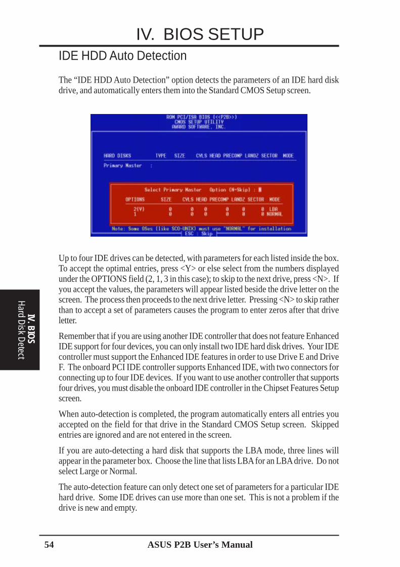
54 ASUS P2B User’s Manual
IV. BIOS SETUP
IV. BIOS
Hard D
isk Detect
IDE HDD Auto Detection
The “IDE HDD Auto Detection” option detects the parameters of an IDE hard diskdrive, and automatically enters them into the Standard CMOS Setup screen.
Up to four IDE drives can be detected, with parameters for each listed inside the box.To accept the optimal entries, press <Y> or else select from the numbers displayedunder the OPTIONS field (2, 1, 3 in this case); to skip to the next drive, press <N>. Ifyou accept the values, the parameters will appear listed beside the drive letter on thescreen. The process then proceeds to the next drive letter. Pressing <N> to skip ratherthan to accept a set of parameters causes the program to enter zeros after that driveletter.
Remember that if you are using another IDE controller that does not feature EnhancedIDE support for four devices, you can only install two IDE hard disk drives. Your IDEcontroller must support the Enhanced IDE features in order to use Drive E and DriveF. The onboard PCI IDE controller supports Enhanced IDE, with two connectors forconnecting up to four IDE devices. If you want to use another controller that supportsfour drives, you must disable the onboard IDE controller in the Chipset Features Setupscreen.
When auto-detection is completed, the program automatically enters all entries youaccepted on the field for that drive in the Standard CMOS Setup screen. Skippedentries are ignored and are not entered in the screen.
If you are auto-detecting a hard disk that supports the LBA mode, three lines willappear in the parameter box. Choose the line that lists LBA for an LBA drive. Do notselect Large or Normal.
The auto-detection feature can only detect one set of parameters for a particular IDEhard drive. Some IDE drives can use more than one set. This is not a problem if thedrive is new and empty.
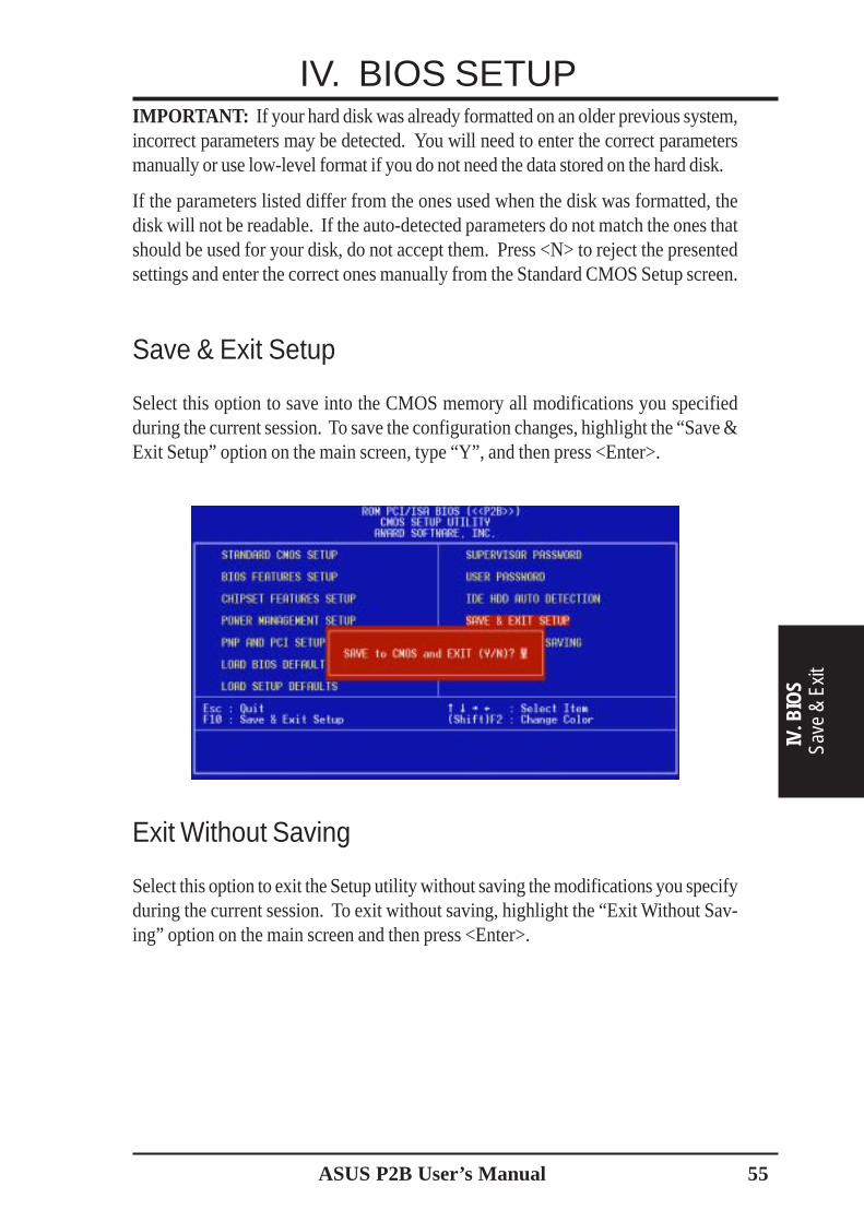
ASUS P2B User’s Manual 55
IMPORTANT: If your hard disk was already formatted on an older previous system,incorrect parameters may be detected. You will need to enter the correct parametersmanually or use low-level format if you do not need the data stored on the hard disk.
If the parameters listed differ from the ones used when the disk was formatted, thedisk will not be readable. If the auto-detected parameters do not match the ones thatshould be used for your disk, do not accept them. Press <N> to reject the presentedsettings and enter the correct ones manually from the Standard CMOS Setup screen.
Save & Exit Setup
Select this option to save into the CMOS memory all modifications you specifiedduring the current session. To save the configuration changes, highlight the “Save &Exit Setup” option on the main screen, type “Y”, and then press <Enter>.
Exit Without Saving
Select this option to exit the Setup utility without saving the modifications you specifyduring the current session. To exit without saving, highlight the “Exit Without Sav-ing” option on the main screen and then press <Enter>.
IV. BIOS SETUP
IV. B
IOS
Save
& E
xit

56 ASUS P2B User’s Manual
V. SOFTW
ARED
MI Introduction
Introducing the ASUS DMI Configuration UtilityThis motherboard supports DMI within the BIOS level and provides a DMI Configu-ration Utility to maintain the Management Information Format Database (MIFD).DMI is able to auto-detect and record information pertinent to a computer’s systemsuch as the CPU type, CPU speed, and internal/external frequencies, and memorysize. The onboard BIOS will detect as many system information as possible and storethose collected information in a 4KB block in the motherboard’s Flash EPROM andallow the DMI to retrieve data from this database. Unlike other BIOS software, theBIOS on this motherboard uses the same technology implemented for Plug and Playto allow dynamic real-time updating of DMI information versus creating a new BIOSimage file and requiring the user to update the whole BIOS. This DMI ConfigurationUtility also allows the system integrator or end user to add additional information intothe MIFD such as serial numbers, housing configurations, and vendor information.Those information not detected by the motherboard BIOS and has to be manuallyentered through the DMI Configuration Utility and updated into the MIFD. ThisDMI Configuration Utility provides the same reliability as PnP updating and willprevent the refreshing failures associated with updating the entire BIOS.
System RequirementsThe DMI Configuration Utility (DMICFG2.EXE) must be used in real mode in orderfor the program to run, the base memory must be at least 180K. Memory managerslike HIMEM.SYS (required by windows) must not be installed. You can boot upfrom a system diskette without AUTOEXEC.BAT and CONFIG.SYS files, “REM”HIMEM.SYS in the CONFIG.SYS, or press <F5> during bootup to bypass yourAUTOEXEC.BAT and CONFIG.SYS files.
V. SUPPORT SOFTWAREDesktop Management Interface (DMI)

ASUS P2B User’s Manual 57
V. S
OFT
WAR
EU
sing
DM
I Util
ity
V. SUPPORT SOFTWAREUsing the ASUS DMI Configuration Utility
NOTE: The following screen displays are provided as examples only and may notreflect the screen contents on your system.
Edit DMI (or delete)
Use the ←→ (left-right) cursors to move the top menu items and the ↑↓ (up-down)cursor to move between the left hand menu items. The bottom of the screen willshow the available keys for each screen. Press enter at the menu item to enter theright hand screen for editing. “Edit component” appears on top. The reversed colorfield is the current cursor position and the blue text are available for editing. Theorange text shows auto-detected information and are not available for editing. Theblue text “Press [ENTER] for detail” contains a second pop-up menu is available,use the + - (plus-minus) keys to change the settings. Enter to exit and save, ESC toexit and not save.
If the user has made changes, ESC will prompt you to answer Y or N. Enter Y to goback to the left-hand screen and save, enter N to go back to left-hand screen and notsave. If editing has not been made, ESC will send you back to the left hand menuwithout any messages.
NotesA heading, *** BIOS Auto Detect ***, appears on the right for each menu item onthe left side that has been auto detected by the system BIOS.
A heading, *** User Modified ***, will appear on the right for menu items thathave been modified by the user.

58 ASUS P2B User’s Manual
V. SOFTW
AREU
sinAg DM
I Utility
V. SUPPORT SOFTWARESave MIFD
You can save the MIFD (normally only saved to flash ROM) to a file by entering thedrive and path here. If you want to cancel save, you may press ESC and a message“Bad File Name” appears here to show it was not saved.
Load MIFD
You can load the disk file to memory by entering a drive and path and file name here.
Load BIOS Defaults
You can load the BIOS defaults from a MIFD file and can clear all user modified andadded data. You must reboot your computer in order for the defaults to be saved backinto the Flash BIOS.

ASUS P2B User’s Manual 59
VI. APPENDIXThe ASUS CIDB Chassis Intrusion Sensor ModuleThe optional ASUS CIDB is a module for providing audio alarm and logging whenthere is an intrusion into the chassis of a computer system. The module detects a chas-sis intrusion by either light striking its photo sensor or by contact when its switchconnectors are shorted by chassis-mounted momentary toggle switches. An intrusionmemory function allows detection by BIOS and LDCM on the next bootup.
Buzzer to sound the alarm
Photo sensor to detect intrusion by light
Intrusion memory
Photo sensor sensitivity adjustment
Chassis connectorextension cable
Battery for the memory
Connector to dock with the motherboard’s chassis connector
Two switch connectors to detect intrusion by chassismounted micro switches
Using the ASUS CIDB1. You must have an ASUS motherboard with a chassis connector.2. Connect the CIDB directly to the chassis connector or use the provided extension
cable and mount the CIDB to the chassis using a double-sided foam adhesive tape.
CAUTION! The CIDB component pins and metallic points must not come incontact with another metallic surface or else shorting will occur!
3. Check the hardware settings:• JP1 jumper should be enabled to use the photo sensor• MS1 and MS2 connectors should be connected to momentary toggle switches
mounted on the chassis to use the contact method for triggering alarms.• SW jumper should be enabled to allow the hardware monitoring compo-
nents to receive signals from the CIDB.4. To stop the alarm from sounding, use the LDCM software or place a jumper on
(or short manually) the CLR jumper momentarily.5. If you have an updated BIOS with intrusion support, booting the computer after
an intrusion will require a password which is configured through BIOS.
VI. A
PPEN
DIX
ASUS
CID
B M
odule
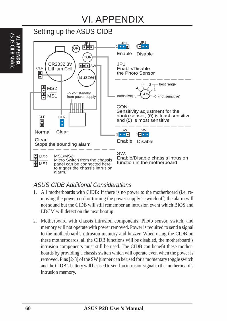
ASUS P2B User’s Manual60
VI. APPENDIX
Normal Clear
Clear:Stops the sounding alarm
CLR CLR
Enable Disable
JP1:Enable/Disablethe Photo Sensor
JP1 JP11 1
MS1
MS2 MS1/MS2:Micro Switch from the chassispanel can be connected hereto trigger the chassis intrusionalarm.
Enable Disable
SW:Enable/Disable chassis intrusionfunction in the motherboard
SW SW1 1
Setting up the ASUS CIDB
CON:Sensitivity adjustment for thephoto sensor, (0) is least sensitiveand (5) is most sensitive
CON1
234
5 0 (not sensitive)
best range
(sensitive)
CR2032 3VLithium Cell
Buzzer
MS1
CLR
JP1
CON
OR
SW
MS2+5 volt standbyfrom power supply
ASUS CIDB Additional Considerations1. All motherboards with CIDB: If there is no power to the motherboard (i.e. re-
moving the power cord or turning the power supply’s switch off) the alarm willnot sound but the CIDB will still remember an intrusion event which BIOS andLDCM will detect on the next bootup.
2. Motherboard with chassis intrusion components: Photo sensor, switch, andmemory will not operate with power removed. Power is required to send a signalto the motherboard’s intrusion memory and buzzer. When using the CIDB onthese motherboards, all the CIDB functions will be disabled, the motherboard’sintrusion components must still be used. The CIDB can benefit these mother-boards by providing a chassis switch which will operate even when the power isremoved. Pins [2-3] of the SW jumper can be used for a momentary toggle switchand the CIDB’s battery will be used to send an intrusion signal to the motherboard’sintrusion memory.
VI. APPENDIXASUS CIDB M
odule

ASUS P2B User’s Manual 61
VI. APPENDIXThe ASUS S370 CPU CardThe optional ASUS S370 CPU card allows Slot 1 motherboards to accept socket 370processors. The ASUS S370 CPU card gives Slot 1 motherboard owners an inexpen-sive way to upgrade their Pentium II computers using lower costing socket 370 pro-cessors. Since socket 370 processors are based on the Pentium II design, the onlydifference is the connector and the amount of internal cache within the processor.
The following picture shows the ASUS S370 CPU card with a plastic retainer at-tached to the edge. The retainer is used to hold the ASUS S370 CPU card in placeusing the motherboard’s Slot 1 retention mechanism.
Using the ASUS S370The general procedure for using the ASUS S370 CPU card:
1. Check the voltage setting for your socket 370 processor using the jumpers onthe card if necessary. For current socket 370 processors, the default setting shouldbe used. See the reverse side of the ASUS S370 CPU card or the next page forvoltage settings.
2. Install the socket 370 processor. Installation of socket 370 processors is exactlylike socket 7 processors. Lift the brown lever to 90° to install the processor andlower the brown lever to lock the processor.
3. Insert the ASUS S370 CPU card into Slot 1 on the motherboard. The two finson the sides of the ASUS S370 CPU card must catch on the retention mecha-nism so that it locks in place.
4. Connect the socket 370 processor’s fan connector to the motherboard.5. Make sure that no wires or objects come in contact with the fan.
FinFin
Slot 1 Compatible Connector
ASUS S370 CPU Card Retainer
VI. A
PPEN
DIX
ASUS
S37
0 CP
U Ca
rd

ASUS P2B User’s Manual62
VI. APPENDIXSetting up the ASUS S370
So
cket 3
70
JP1JP2JP3JP4JP5
CPU Voltage
Screw Hole Screw Hole
Brown Lever
Socket 370 CPU Voltage
1.80Volts
1 2 3JP5JP4
JP2JP1
JP3
1.85Volts
1 2 3JP5JP4
JP2JP1
JP3
1.90Volts
1 2 3JP5JP4
JP2JP1
JP3
1.95Volts
1 2 3JP5JP4
JP2JP1
JP3
2.05Volts
1 2 3JP5JP4
JP2JP1
JP3
2.00Volts
1 2 3JP5JP4
JP2JP1
JP3
2.10Volts
1 2 3JP5JP4
JP2JP1
JP3
2.20Volts
1 2 3JP5JP4
JP2JP1
JP3
2.30Volts
1 2 3JP5JP4
JP2JP1
JP3
2.40Volts
1 2 3JP5JP4
JP2JP1
JP3
2.50Volts
1 2 3JP5JP4
JP2JP1
JP3
CPU Def.
1 2 3JP5JP4
JP2JP1
JP3
2.60Volts
1 2 3JP5JP4
JP2JP1
JP3
Reserved
1 2 3JP5JP4
JP2JP1
JP3
ASUS S370 Jumper SettingsSetting the CPU voltage is not necessary for current socket 370 processors. If re-quired, your socket 370 processor should have its voltage requirement printed on itssurface or documentation. If no voltage is indicated or you are not sure, use the“CPU Def.” setting as shown below.
WARNING! Exceeding your socket 370 processor’s required voltage can dam-age your processor permanently! Make sure that the jumpers are as shown for“CPU Def.” unless otherwise specified before powering on your motherboard.
VI. APPENDIXASUS S370 CPU Card

ASUS P2B User’s Manual 63
VI. APPENDIXASUS PCI-L101 Fast Ethernet Card
LAN ActivityOutput Signal
RJ45
LED
s
Motherboard typeWake on LANOutput Signal
ASUS
Other
IntelChipset
If you are using the ASUS PCI-L101 on an ASUS motherboard, leave the jumper onits defaut setting of “ASUS.” If you are using another brand of motherboard, set thejumper to “Other.” Connect the Wake on LAN (WOL) output signal to themotherboard’s WOL_CON in order to utilize the wake on LAN feature of the moth-erboard. Connect the LAN activity output signal (LAN_LED) to the system cabinet’sfront panel LAN_LED in order to display the LAN data activity.
VI. A
PPEN
DIX
ASUS
LAN
Car
d
ASUS P2B User’s Manual64
VI. APPENDIXFeatures• Intel 82558 Ethernet LAN Controller (Fully integrated 10BASE-T/100BASE-TX)• Wake-On-LAN Remote Control Function Supported• PCI Bus Master Complies to PCI Local Bus Rev. 2.1 specifications• Consists of MAC & PHY (10/100Mbps) interfaces• Complies to IEEE 802.3 10BASE-T and IEEE 802.3u 100BASE-TX interfaces• Fully supports 10BASE-T & 100BASE-TX operations through a single RJ45 port• Supports 32-bit Bus Master Technology / PCI Rev. 2.1• Enhancements on ACPI & APM• Adheres to PCI Bus Power Management Interface Rev. 1.0, ACPI Rev. 1.0, and
Device Class Power Management Rev. 1.0• IEEE 802.3u auto-negotiation for 10Mbps/100Mbps Network Data Transfer
Rates.• Provides LED indicators for monitoring network conditions• Plug and Play
Software Driver Support• NetWare ODI Drivers - Novell Netware 3.x, 4.x, DOS, OS/2 Client• NDIS 2.01 Drivers - Microsoft LAN Manager, Microsoft Windows 3.11, IBM
LAN Server• NDIS 3.0 Drivers - Microsoft Windows NT, Microsoft Windows 95, Microsoft
Windows 3.11
Question and AnswerQ: What is Wake-On-LAN ?A: The Wake-On-LAN feature provides the capability to remotely power on sys-
tems supporting Wake-On-LAN by simply sending a wake-up frame. With thisfeature, remotely uploading/downloading data to/from systems during off-peakhours will be feasible.
Q: What can Wake-On-LAN do for you ?A: Wake-On-LAN is a remote management tool with advantages that can reduce
system management workload, provide flexibility to the system administrator’sjob, and then of course save you time-consuming efforts and costs.
Q: What components does Wake-On-LAN require to be enable?A: To enable Wake-On-LAN function, your system requires Ethernet LAN adapter
card that can activate Wake-On-LAN function, a client with Wake-On-LAN capa-bility, and software such as LDCM Rev. 3.10 or up that can trigger wake-up frame.
VI. APPENDIXASUS LAN Card

ASUS P2B User’s Manual 65
VI. APPENDIX
VI. A
PPEN
DIX
Glos
sary
GlossaryAGP (Accelerated Graphics Port)An interface specification that enables high-performance 3D graphics on mainstreamPCs. AGP offers a higher throughput than PCI by providing the graphics controllerwith direct access to system memory.
Bus Bus Frequency Bus Speed
PCI 33MHz 133MB/sAGP 1X 66MHz 200-300MB/sAGP 2X 133MHz 528MB/sAGP 4X 266MHz 1 GB/s
AUTOEXEC.BATAUTOEXEC.BAT is a special-purpose file that is automatically executed by DOSwhenever the computer is turned ON or restarted. This file contains important com-mands that help configure the system to work with certain software and devices.Windows 95 and later has its own startup files and may not use or may ignore partsof the AUTOEXEC.BAT file.
BIOS (Basic Input/Output System)BIOS is a set of routines that affect how the computer transfers data between com-puter components, such as memory, disks, and the display adapter. The BIOS in-structions are built into the computer’s read-only memory. BIOS parameters can beconfigured by the user through the BIOS Setup program. The BIOS can be updatedusing the provided utility to copy a new BIOS file into the EEPROM.
Bit (Binary Digit)Represents the smallest unit of data used by the computer. A bit can have one of twovalues: 0 or 1.
BootBoot means to start the computer operating system by loading it into system memory.When the manual instructs you to “boot” your system (or computer), it means toturn ON your computer. “Reboot” means to restart your computer. When using Win-dows 95 or later, selecting “Restart” from “Start | Shut Down...” will reboot yourcomputer.
Bus Master IDEPIO (Programmable I/O) IDE requires that the CPU be involved in IDE access andwaiting for mechanical events. Bus master IDE transfers data to/from the memorywithout interrupting the CPU. Bus master IDE driver and bus master IDE hard diskdrives are required to support bus master IDE mode.
ASUS P2B User’s Manual66
VI. APPENDIX
VI. APPENDIXGlossary
Byte (Binary Term)One byte is a group of eight contiguous bits. A byte is used to represent a singlealphanumeric character, punctuation mark, or other symbol.
COM PortCOM is a logical device name used by to designate the computer serial ports. Point-ing devices, modems, and infrared modules can be connected to COM ports. EachCOM port is configured to use a different IRQ and address assignment.
CPU (Central Processing Unit)The CPU, sometimes called “Processor,” actually functions as the “brain” of thecomputer. It interprets and executes program commands and processes data storedin memory. Currently, there are socket 370 (for Pentium Celeron-PPGA), socket 7(for Pentium, AMD, Cyrix, IBM), slot 1 (for Pentium II and III), and slot 2 (forXeon) processors.
Device DriverA device driver is a special set of instructions that allows the computer’s operating sys-tem to communicate with devices such as VGA, audio, ethernet, printer, or modem.
DOS (Disk Operating System)DOS is the foundation on which all other programs and software applications oper-ate, including Windows. DOS is responsible for allocating system resources such asmemory, CPU time, disk space, and access to peripheral devices. For this reason,DOS constitutes the basic interface between you and your computer.
HardwareHardware is a general term referring to the physical components of a computer sys-tem, including peripherals such as printers, modems, and pointing devices.
IDE (Integrated Drive Electronics)IDE devices integrate the drive control circuitry directly on the drive itself, elimi-nating the need for a separate adapter card (in the case for SCSI devices). UltraDMA/33 IDE devices can achieve up to 33MB/Sec transfer.
LPT Port (Line Printer Port)Logical device name reserved by DOS for the computer parallel ports. Each LPTport is configured to use a different IRQ and address assignment.
MMXA set of 57 new instructions based on a technique called Single Instruction, MultipleData (SIMD), which is built into the new Intel Pentium PP/MT (P55C) and PentiumII (Klamath) CPU as well as other x86-compatible microprocessors. The MMX in-structions are designed to accelerate multimedia and communications applications,such as 3D video, 3D sound, video conference.
ASUS P2B User’s Manual 67
VI. APPENDIX
VI. A
PPEN
DIX
Glos
sary
PCI Bus (Peripheral Component Interconnect Local Bus)PCI bus is a specification that defines a 32-bit data bus interface. PCI is a standardwidely used by expansion card manufacturers.
PeripheralsPeripherals are devices attached to the computer via I/O ports. Peripheral devicesallow your computer to perform an almost limitless variety of specialized tasks.
POST (Power On Self Test)When you turn on the computer, it will first run through the POST, a series of soft-ware-controlled diagnostic tests. The POST checks system memory, the mother-board circuitry, the display, the keyboard, the diskette drive, and other I/O devices.
PS/2 PortPS/2 ports are based on IBM Micro Channel Architecture. This type of architecturetransfers data through a 16-bit or 32-bit bus. A PS/2 mouse and/or keyboard may beused on ATX motherboards.
RAID (Redundant Array of Independent Disks)RAID can be set up to provide mirroring (for fault tolerance), parity (for data guard-ing), or striping (for data distribution over several drives for increased performance).A RAID card is required to setup a RAID system.
RAM (Random Access Memory)There are several different types of RAM such as DRAM (Dynamic RAM), EDODRAM (Extended Data Output DRAM), SDRAM (Synchronous DRAM).
ROM (Read Only Memory)ROM is nonvolatile memory used to store permanent programs (called firmware)used in certain computer components. Flash ROM (or EEPROM) can be repro-grammed with new programs (or BIOS).
SCSI (Small Computer System Interface)High speed parallel interface defined by the X3T9.2 committee of the AmericanNational Standards Institute (ANSI) for connecting many peripheral devices.
System DiskA system disk contains the core file of an operating system and is used to boot up theoperating system.
Ultra DMA/33Ultra DMA/33 is a new specification to improve IDE transfer rates. Unlike tradi-tional PIO mode, which only uses the rising edge of IDE command signal to transferdata, the DMA/33 uses both rising edge and falling edge. Hence, the data transferrate is double of the PIO mode 4 or DMA mode 2. (16.6MB/s x2 = 33MB/s).

ASUS P2B User’s Manual68
VI. APPENDIX
VI. APPENDIXGlossary
USB (Universal Serial Bus)A new 4-pin serial peripheral bus that allows plug and play computer peripheralssuch as keyboard, mouse, joystick, scanner, printer and modem/ISDN to be auto-matically configured when they are attached physically without having to installdrivers or reboot. With USB, the traditional complex cables from back panel of yourPC can be eliminated.