user manual xpl rail 4m - r3a30 -...
TRANSCRIPT

User manual XPL Rail 4M - R3A30
I2SE GmbH
January 17, 2017
1/20

CONTENTS CONTENTS
Contents
1 Your XPL Rail 4M - R3A30 41.1 Notes regarding this manual . . . . . . . . . . . . . . . . . . . . . . . . . . . . . . . . . . . . . . 41.2 Proper Use . . . . . . . . . . . . . . . . . . . . . . . . . . . . . . . . . . . . . . . . . . . . . . . 41.3 I2SE on the Internet . . . . . . . . . . . . . . . . . . . . . . . . . . . . . . . . . . . . . . . . . . 5
2 Function 5
3 Installation 63.1 Important safety instructions . . . . . . . . . . . . . . . . . . . . . . . . . . . . . . . . . . . . . . 63.2 Installation of the device . . . . . . . . . . . . . . . . . . . . . . . . . . . . . . . . . . . . . . . . 6
4 Putting into service 84.1 Putting into service the Powerline connection by means of the push button method . . . . . . . . . 94.2 Putting into service the Powerline connection using software . . . . . . . . . . . . . . . . . . . . . 104.3 Configuration of the XPL Rail device . . . . . . . . . . . . . . . . . . . . . . . . . . . . . . . . . . 10
4.3.1 Locating the device in the network . . . . . . . . . . . . . . . . . . . . . . . . . . . . . . . 104.3.2 Startscreen . . . . . . . . . . . . . . . . . . . . . . . . . . . . . . . . . . . . . . . . . . . 114.3.3 Physical IO channel configuration . . . . . . . . . . . . . . . . . . . . . . . . . . . . . . . 124.3.4 Virtual Channels . . . . . . . . . . . . . . . . . . . . . . . . . . . . . . . . . . . . . . . . 124.3.5 Network configuration . . . . . . . . . . . . . . . . . . . . . . . . . . . . . . . . . . . . . . 144.3.6 Powerline . . . . . . . . . . . . . . . . . . . . . . . . . . . . . . . . . . . . . . . . . . . . 154.3.7 Maintenance . . . . . . . . . . . . . . . . . . . . . . . . . . . . . . . . . . . . . . . . . . 15
5 Interface for third-party software 16
6 LED States 176.1 PLC . . . . . . . . . . . . . . . . . . . . . . . . . . . . . . . . . . . . . . . . . . . . . . . . . . . 176.2 IP . . . . . . . . . . . . . . . . . . . . . . . . . . . . . . . . . . . . . . . . . . . . . . . . . . . . 176.3 LED for each physical channel . . . . . . . . . . . . . . . . . . . . . . . . . . . . . . . . . . . . . 17
7 Touch Button 17
8 Application Examples 18
9 Maintenance and Cleaning 18
10 Technical Data 18
11 Legal Notes 1911.1 Licenses . . . . . . . . . . . . . . . . . . . . . . . . . . . . . . . . . . . . . . . . . . . . . . . . 1911.2 Disposal . . . . . . . . . . . . . . . . . . . . . . . . . . . . . . . . . . . . . . . . . . . . . . . . 20
2/20

CONTENTS CONTENTS
Revisions
Revision Released Changes3 January 17, 2017 Add notes about IO channel states and Powerline Ethernet adapter
limitations2 December 19, 2016 synchronized product name spellings, configuration backup/restore
mentioned, powerline page documented1 May 30, 2016 initial release
Copyright c©2015-2016 I2SE GmbHAll rights reserved. This operating instruction may not be reproduced in any way, whether in whole or in part, orcopied or processed using any electronic, mechanical or chemical method without the prior written approval of thepublisher.Any information in this document has been compiled with great care, but may not be deemed an assurance ofproduct characteristics. I2SE shall be liable solely to the degree specified in the terms of sale and delivery.Distribution and reproduction of the documentation and software supplied with this product and the use of its contentis subject to prior written approval by I2SE.I2SE reserves the right to make changes due to technical progress.BrandsHomePlug R© is a registered trademark of HomePlug Powerline Alliance.Linux R© is a registered trademark of Linus Torvalds.Ubuntu R© is a registered trademark of Canonical Ltd.iPhone R©, iPad R©, iPod R©, Mac R© und Mac OS X R© are registered trademarks of Apple Computer, Inc.Windows R© and Microsoft R© are registered trademarks of Microsoft Corp.Fritz!Box R© and Fritz!Powerline are registered trademarks of AVM GmbH.devolo and dLAN R© are registered trademarks of devolo AG.
All other names mentioned may be trademarks or registered trademarks of their respective owners. I2SE reservesthe right to modify the mentioned data without notice and assumes no liability for technical inaccuracies and/oromissions.I2SE GmbHFriedrich-Ebert-Str. 6104109 LeipzigGermany
http://www.i2se.com/
3/20

1 YOUR XPL RAIL 4M - R3A30
1 Your XPL Rail 4M - R3A30
Thank you very much for your trust. We are happy that you have choosen an XPL Rail device. With only a few stepsyour device is ready for use and can perform your control applications.
1.1 Notes regarding this manual
Please read this manual carefully before commissioning your XPL Rail device.Keep this manual and / or the installation guide for later reference.The manual is to be considered as a part of the device and has to be passed together with it if you hand it to otherpersons.Used Symbols:
Attention! A hazard is pointed out.
Note. This section contains additional important information.
1.2 Proper Use
The device is part of the supply network. The applicable standards and guidelines of the specific country areto be fulfilled while planning and installation. The device may only be operated in 230V/50Hz mains circuits. Onlyelectrically qualified persons are allowed to work on mains circuits. The usual regulations for prevention of accidentsare to be followed. To prevent electrical shock you have to disconnect mains from the circuit you are working on.Not following those installation instructions may lead to fire or danger for life.Do only operate the device indoor and prevent the influence of moisture, dust as well as sun- and other headradiation. Only load the device up to the specified limits. Exceeding those limits may damage the device and canlead to fire or danger for life.The devices are not to be used for electrically safe disconnection from mains.The device may not be opened by the user. Opening the device exposes you to the danger of electric shock.The device is free of maintanance for the operator. In the case the device is damaged disconnect it from it’s supplyand hand it over to trained service staff.A damage may be:
• the power cord is damaged
• the device had contact to moisture
• the device does not operate after correct installation
• the case of the device is broken
For electrical connection to the device terminals please note the specified lead types and stripping lengths in thedatasheet.
Please note the regulatory requirements for installations in distribution boards.
4/20
1.3 I2SE on the Internet 2 FUNCTION
1.3 I2SE on the Internet
More information about our products and about Powerline Communication can be found on our websitewww.i2se.com.On the product page for your device you can find product description, documentation as well as updated firmware.If you have further ideas about our products please contact us via E-Mail at [email protected].
2 Function
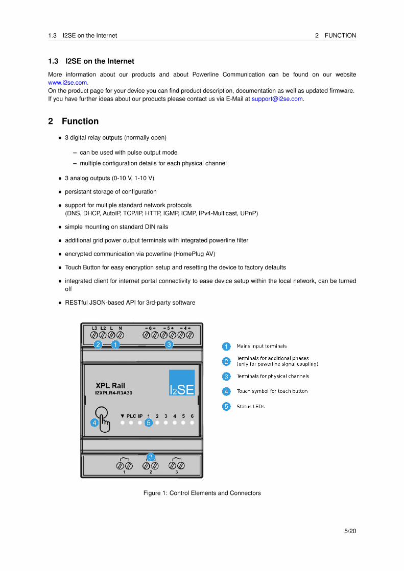
• 3 digital relay outputs (normally open)
– can be used with pulse output mode
– multiple configuration details for each physical channel
• 3 analog outputs (0-10 V, 1-10 V)
• persistant storage of configuration
• support for multiple standard network protocols(DNS, DHCP, AutoIP, TCP/IP, HTTP, IGMP, ICMP, IPv4-Multicast, UPnP)
• simple mounting on standard DIN rails
• additional grid power output terminals with integrated powerline filter
• encrypted communication via powerline (HomePlug AV)
• Touch Button for easy encryption setup and resetting the device to factory defaults
• integrated client for internet portal connectivity to ease device setup within the local network, can be turnedoff
• RESTful JSON-based API for 3rd-party software
Figure 1: Control Elements and Connectors
5/20

3 INSTALLATION
3 Installation
3.1 Important safety instructions
The following safety instructions must be read carefully and clearly understood prior to the assembly of the device.Please keep these safety instructions for future reference.
• The installation and assembly may only be carried out by a qualified electrician.
• This device, which is supplied with mains power, has to be secured by means of a max. B16Acircuit breaker. In case of a multi-phase connection, such a circuit breaker has to be provided for eachconnected outer conductor. These circuit breakers are to be installed directly next to each other.
• This device is designed for installation on DIN rails which provide fire protection as per DIN EN 60950-1.
• The device may only be installed in dry areas.
• Do not insert any objects in the slots and openings on the housing.
• Make sure that the device is not exposed to heat sources which may lead to overheating.
• Ensure adequate ventilation at the site of installation.
• The device may only be connected in the range of overvoltage category 3 or lower.
• The device may not be opened by the user. The interior of the housing does not contain any parts to bemaintained.
• Do not operate the device in supply networks which do not comply with the specifications on the type plate.
3.2 Installation of the device
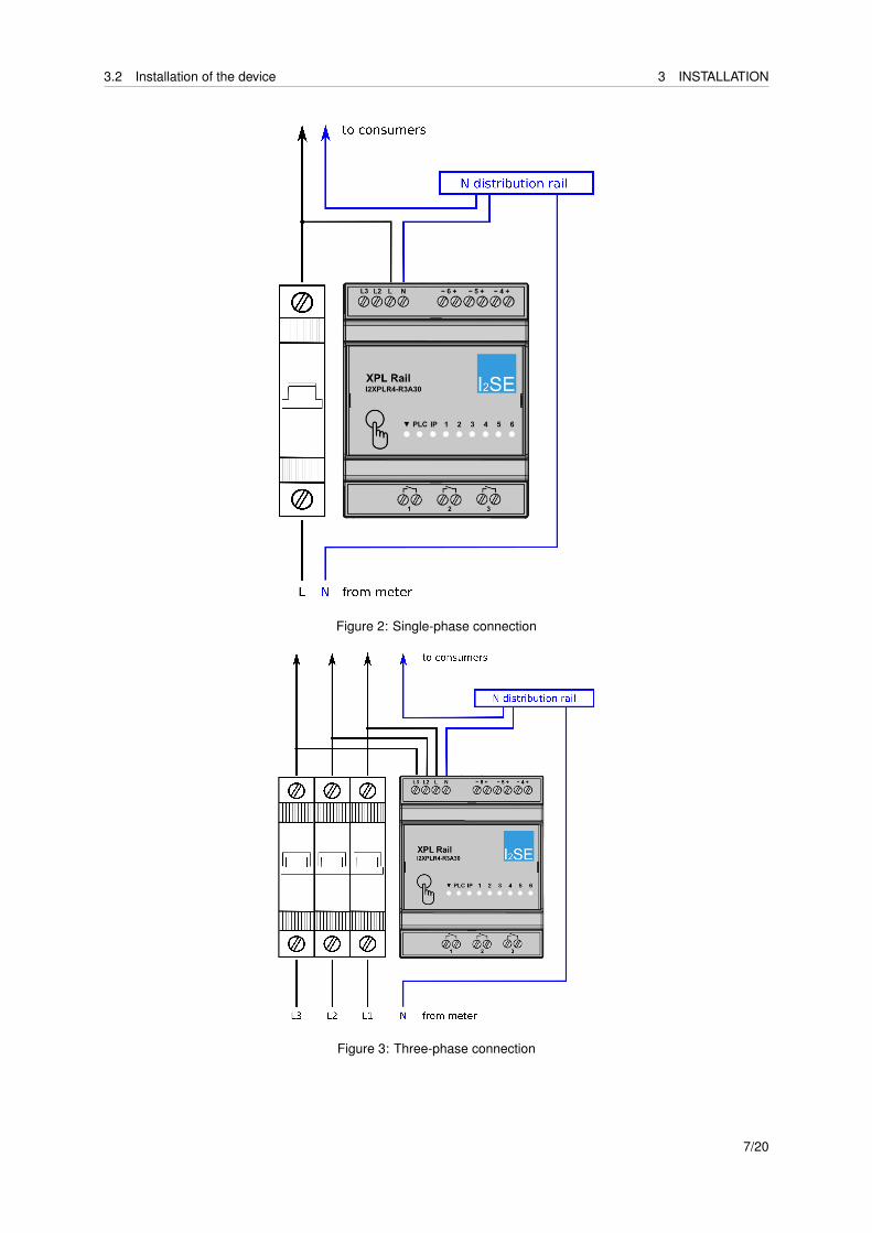
Place the DIN rail mounted device on the DIN rail and snap it. Make sure that the catch spring is completely snappedin and the device is firmly attached to the rail.Strip the wire ends of the mains supply line to a length of 8mm without damaging the plain core. Please observethe allowed line cross-sections.Wire the mains supply with the 230V mains voltage in accordance with the following circuit diagrams. In case of asingle-phase connection (see Figure 2) only L and N are to be connected. In case of a three-phase connection (seeFigure 3), all phases are to be connected, whereas the connection of phases 2 and 3 is only used to communicatevia several phases. Only connection L is used for power supply besides communication.
Only electrically qualified persons may connect the relay outputs.After the electrical connection has been established, all connections must be protected from accidental contactusing a cover before the power can be switched on.
6/20
3.2 Installation of the device 3 INSTALLATION
Figure 2: Single-phase connection
Figure 3: Three-phase connection
7/20

4 PUTTING INTO SERVICE
4 Putting into service
Before an XPL Rail can be completely put into service, it may be necessary in most cases to parametrize the deviceor the terminals following the installation, depending on the customer situation. For this purpose, a computer (ornotebook) with browser (for example Microsoft Internet Explorer, Mozilla Firefox, Google Chrome or Apple Safari) isrequired for the configuration of the device. For this purpose, the computer must be capable of accessing the XPLRail via the Powerline connection. It is recommended to use a standard-type Powerline Ethernet adapter. Theseadapters are available with different characteristics (for example only with LAN or with LAN and Wi-Fi, differentspeeds) at various providers. XPL Rail devices are compatible with any adapter manufactured as per HomePlug AVstandard, i.e. they are compatible with any adapters designed for a speed of at least 200MBit. It is a prerequisitefor the next steps to successfully put into service such a Powerline Ethernet adapter. Please read the suppliedinstruction of the Powerline Ethernet adapter manufacturer as well. The easiest way is to connect the PowerlineEthernet adapter with a wall-mounted socket and to connect it to the existing router (see Figure 4) by means of anetwork cable. A direct connection between the computer and the Powerline Ethernet adapter can be establishedas well (see Figure 5).
Figure 4: Connection between notebook and XPL Rail via router and Powerline Ethernet adapter
Figure 5: Direct connection between notebook and XPL Rail via router and Powerline Ethernet adapter
Then, follow the steps as described in Putting into service the Powerline connection by means of push button
8/20

4.1 Putting into service the Powerline connection by means of the push button method4 PUTTING INTO SERVICE
method or Putting into service the Powerline connection using software. Both methods have advantagesand disadvantages. The first method is recommended if the manufacturer of the Powerline Ethernet adapter doesnot supply any software, or the software is not (yet) installed or can or shall not be used. If such a softwareis available and ready-to-use, it is recommended to use it as it can usually graphically represent the Powerlinenetwork. Furthermore, the user can get a better understanding of the Powerline network.The following solutions are, among others, available for the respective products of the manufacturers:
• AVM GmbH: FRITZ!Powerline for Powerline adapter of the same-named series
• Devolo AG: devolo Cockpit for devolo’s dLAN R© products
By default, HomeplugAV-compatible individual devices supplied are encrypted with the standard password Home-PlugAV. Thus, these individual devices can be immediately combined with HomeplugAV-compatible devices of othermanufacturers which have this standard password as well. The disadvantage of this standard password is that itdoes not provide any confidentiality and it enables a crosstalk between network packages, for example, in apartmentbuildings. It is strongly recommended to configure an individual encryption for the own Powerline network. Pleaseread the instruction of your Powerline Ethernet adapter for further information.Notes:
• The use of the Powerline Ethernet adapter is only necessary to access the configuration interface of an XPLRail by means of a computer and browser. Depending on the application, the Powerline Ethernet adapter isthen no longer required and can be removed (for example, if no network connection is required or desiredand only XPL Rail are to be coupled together).
• Please note that the number of nodes in a Powerline network may be restricted by the Powerline Ethernetadapter. For the exact number, refer to the manufacturer’s documentation.
In order to simplify the selection of a suitable Powerline Ethernet adapter, we selected some examples. Theseadapters are compatible with the XPL Rail family and support at least 64 nodes in the Powerline network:
• Allnet ALL1681205
• Devolo dLAN 1200+
• TP-LINK TL-PA8010P AV1200
• Netgear PLP1200-100PES
• AVM FRITZ!Powerline 1000E
4.1 Putting into service the Powerline connection by means of the push button method
The connection between the Powerline Ethernet adapter and the XPL Rail is established as follows:
1. Place your finger on the touch symbol on the front panel for 5 to 8 seconds until the PLC LED lights up inorange. After removing the finger, a potential already stored Powerline password will be deleted. The devicewill generate a random password and stores it internally. The PLC LED light ups in red and shows the newcondition as no Powerline connection to another device is established.
2. A pushbutton or the like has to be pressed on the Powerline Ethernet adapter, which establishes the con-nection to the router or the computer, in order to start the coupling process. Depending on the manufacturer,this pushbutton can have different names. Please read the operating instruction of your Powerline Ethernetadapter. Usually, this process is indicated by means of a flashing LED.
3. Now, place your finger on the touch symbol on the XPL Rail for 1 to 3 seconds. As soon as the PLC LEDlights up green, the finger can be removed and the PLC LED starts flashing. This indicates that the XPL Railhas started to join an existing network.
It may take up to one minute until the joining to the Powerline network is completed following the last step on theXPL Rail. This depends, among others, on the signal quality of the Powerline network. If no connection could beestablished to a Powerline network, the PLC LED on the XPL Rail lights up red again. Please note that the PLCLED can also light up red for a few seconds after successfully joining a network. Subsequently, however, it shouldbe permanently lit green.Notes:
9/20

4.2 Putting into service the Powerline connection using software 4 PUTTING INTO SERVICE
• The time between pressing the pushbutton on the Powerline Ethernet adapter and removing the finger fromthe touch symbol on the XPL Rail may not exceed 2 minutes.
• Furthermore, it is only possible to add one single device to the Powerline network at a time. This process isto be repeated if several XPL rails are to be put into service.
4.2 Putting into service the Powerline connection using software
You can also add the device by means of DAK (Device Access Key, often also called device password or security ID)to an existing Powerline network or couple it with a Powerline Ethernet adapter. The DAK is indicated on the devicelabel of the XPL Rail. It consists of 4 x 4 letters, separated by hyphens, for example: COSE-NOW-LAXU-VAYU.Note this DAK and install the device in the power grid.
Figure 6: Example label for XPL Rail 4M - R3A30
After the device has been put into service, you can add the device to the existing Powerline network using thesoftware of your Powerline Ethernet adapter (for example FRITZ!Powerline or devolo Cockpit). In doing so, the DAKis to be entered. Please refer to the documentation of your Powerline Ethernet adapter for further information aboutthis process.
4.3 Configuration of the XPL Rail device
4.3.1 Locating the device in the network
here are several possibilities to access the configuration interface if the XPL Rail is connected to the router of alocal network by means of a Powerline Ethernet adapter. The configuration interface is provided by an integratedweb server and can be controlled using a browser (for example Internet Explorer, Mozilla Firefox, Google Chromeor Apple Safari). The IP address of the XPL Rail is to be entered in the browser’s address bar in order to open theinterface. By default, the XPL Rail is set to DHCP, i.e. the IP address is dynamically assigned by the router. If anXPL Rail has been set to a static IP address it is sufficient to directly enter the static IP address in order to open theconfiguration interface. Otherwise, there are four ways to find out the IP address of the device:
• via portal connection
1. Open the internet address http://give-me-the.link in the browser.
2. You will get a list of devices in your local network which have been already logged on the portal.
3. Here, you can now click on a link in order to access the configuration interface of the respective device.
4. Please note that this will only work if:
– XPL Rail and browser are connected to the internet via the same router,
10/20

4.3 Configuration of the XPL Rail device 4 PUTTING INTO SERVICE
– the internet access is not blocked by a firewall or the like,– the portal connection in the XPL Rail is not deactivated.
• via UPnP (Universal Plug-and-Play)
1. Open the Windows explorer and search for the ,,Network” symbol.
2. By clicking on the symbol, all devices in the network are listed.
3. All XPL Rail devices found are indicated by means of a symbol. In the as-delivered state, the name ofthe symbol indicates the default host name, which consists of the prefix ,,xplr4-r3a30-” and the last fourcharacters of the MAC address 2. Open the configuration interface by double-clicking this symbol.
4. Please note that this will only work if the UPnP is not blocked by the Windows firewall. In case of doubt,please contact your network and/or system administrator.
Figure 7: UPnP symbol in the network environment
• via DNS resolutionOpen the internet address http://xplr4-r3a30-<mac>/ in the browser. Replace the character string<mac>by the last four characters of the MAC address 2 (for example: if the MAC address 2 is00:01:87:ab:cd:ef, then the internet address is http://xplr4-r3a30-cdef/). xplr4-r3a30-<mac>is thedefault host name of your device. If the router assigns an IP address to your device, it will previously sendthis host name. If supported by your router, the IP address assigned by the router can be assigned to thisname by means of which the browser can then directly access the configuration interface. If you changed thedefault host name, you will have to use your selected host name. Please note that this will only work, if therouter provides this functionality (this applies to most of the models manufactured in 2012 or later, often thiseven applies to previous series).
• via the web interface of your router.Routers (for example FRITZ!Box, Speedport...) often also provide a web interface, containing a list of allknown network devices. Partially, a login is required for the router interface. Please refer to the documentationof your router for further information.
4.3.2 Startscreen
On the startscreen of the configuration website you see a schematical drawing of the device including the coloureddevice LEDs that represent the state of the device and it’s IO channels.If a relay channel is configured without coupling to a virtual channel you can change the state of that channel bytoggling the corresponding switch on the startscreen.For analog output channels the current output is displayed. If it is configured without coupling to a virtual channelyou can change the output value of that channel by typing in the value in an input box.
11/20

4.3 Configuration of the XPL Rail device 4 PUTTING INTO SERVICE
4.3.3 Physical IO channel configuration
On this page you can setup each physical channel individually. A physical channel is a pair of clamps. The labelingof the tabs correspond to the number of the channel.
• Label:can be used to assign an up to 16 characters long name to each channel i.e. ,,livingroom”
• Type:configured the channel as Disabled, Analog input, Digital input, Digital output or S0 input.
• Mode:Depending on the selected Type you have different options:
– Normal - default setting without any of the below specials
– Single pulse - generates an pulse signal on outputs
• Level:selection between Direct und Inverted while Direct passes the signal without change and Invertedinverts the state.
• Delay On time:delays the signal for off-on transitions
• Delay Off time:delays the signal for on-off transitions
• Pulse width:the value of the pulse length
• Assign Virtual Channel/Virtual Channel ID:see chapter Virtual Channels (subsubsection 4.3.4)
Note:
• The actual state of an IO channel is kept in volatile memory, so it may be lost under certain conditions (poweroutage, firmware update, software reset, reset to factory defaults).
Timing Examples for a digital output (DO)
4.3.4 Virtual Channels
Using Virtual Channel inputs and outputs can be coupled across multiple devices. It is distinguished betweenanalog virtual channels and digital virtual channels. Each of this channels is addressed with an ID as integerbetween 1 and 65535.
An analog virtual channel with ID 1 is not linked to digital virtual channel with ID 1. Both can exist inparallel without interference.
12/20
4.3 Configuration of the XPL Rail device 4 PUTTING INTO SERVICE
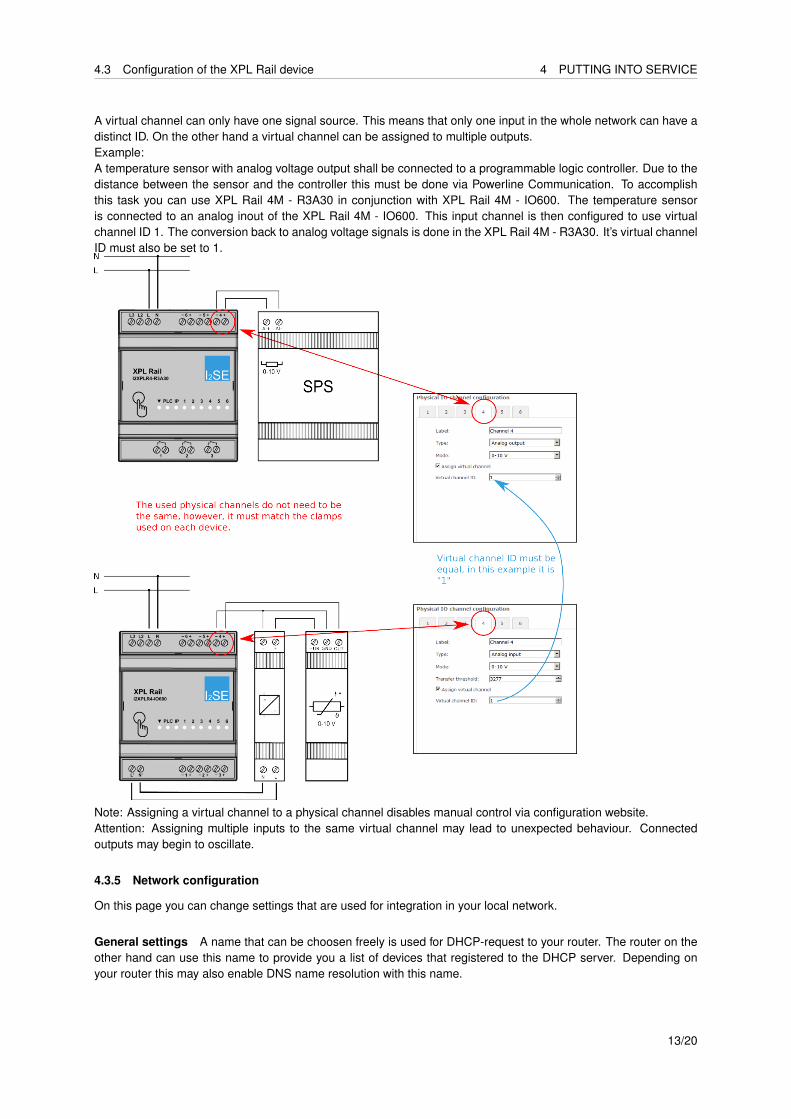
A virtual channel can only have one signal source. This means that only one input in the whole network can have adistinct ID. On the other hand a virtual channel can be assigned to multiple outputs.Example:A temperature sensor with analog voltage output shall be connected to a programmable logic controller. Due to thedistance between the sensor and the controller this must be done via Powerline Communication. To accomplishthis task you can use XPL Rail 4M - R3A30 in conjunction with XPL Rail 4M - IO600. The temperature sensoris connected to an analog inout of the XPL Rail 4M - IO600. This input channel is then configured to use virtualchannel ID 1. The conversion back to analog voltage signals is done in the XPL Rail 4M - R3A30. It’s virtual channelID must also be set to 1.
Note: Assigning a virtual channel to a physical channel disables manual control via configuration website.Attention: Assigning multiple inputs to the same virtual channel may lead to unexpected behaviour. Connectedoutputs may begin to oscillate.
4.3.5 Network configuration
On this page you can change settings that are used for integration in your local network.
General settings A name that can be choosen freely is used for DHCP-request to your router. The router on theother hand can use this name to provide you a list of devices that registered to the DHCP server. Depending onyour router this may also enable DNS name resolution with this name.
13/20

4.3 Configuration of the XPL Rail device 4 PUTTING INTO SERVICE
IPv4 You can select between static IP address and DHCP on this page. When DHCP is selected but no DHCPserver can be found on the network the device selects an IP address according to the Auto-IP-Standard in the range169.254.0.0/16. This allows you to directly connect the device with your PC to get to the configuration website.
It is advisable to temporarily change the Windows firewall settings to allow ,,Network Discovery” in orderto find Auto-IP configured devices via UPnP.For more details regarding this settings talk to your network or system administrator.
Multicast Virtual channels are transmitted via UDP/IP multicast. All devices that shall operate in cooperation witheach other need to have the same multicast address and the same UDP port configured. Usually it is not neededto change the factory defaults (Multicast address: 239.255.255.250; UDP port: 4109). Only change those settingswhen advised to do so by your local network administrator or customer service.
IP discovery client The device connects to an internet server (discovery server) to make finding it in the localnetwork easier, the transmitted data include: the internal IP address, MAC address, hostname and device type. Noother personal data is transmitted.The time interval for the connections to the discovery server can be configured via the parameter Requestinterval and has a default value of 60 seconds. This means that the device connects to the discovery serveronce every minute.
Your network carrier may charge you for this periodic transmission if the included traffic of your internetplan is exceeded.If other discovery mechanisms (see Locating the device in the network (subsubsection 4.3.1)) can be used you canalso disable the IP discovery client completely.
4.3.6 Powerline
This page offers an overview of the powerline network. The first item in the list gives technical details of thecurrent XPL Rail device. Further list items show details of connected powerline devices, e.g. powerline chipset,firmware versions and data rates. It is possible that not all devices of other manufacturers provide all the requestedinformation. The web frontend of other discovered XPL Rail devices can be reached by clicking on the correspondinglist item.Futhermore, this page offers the possibility to add new powerline devices via DAK (Device Access Key) or pushbutton simple connect. Furthermore this page allows setting a new powerline key for the local device or resettingthe powerline configuration to factory defaults.
4.3.7 Maintenance
On this page you can find important device identifiers like model number, serial number but also information aboutthe used firmware version.Furthermore you can update the device firmware on this page. Please regularly check for updates on the manufac-turers website. These updates may fix existing malfunctions of the device as well as add new features.It is also possible to download a backup of the IO channel configuration or to upload such a backup file to restorean IO channel configuration. This helps e.g. to deploy customized IO channel configurations over multiple devices.Via two buttons you may also initiate the following two actions:
1. Reset: forces the device to execute a restart and sets every temporary settings to their initial on state.
2. Blink: Blinks all LEDs of the device for approximately 10 seconds. This function may be used to find a devicein the cabinet where it is mounted amongs multiple other devices of the same type.
14/20

5 INTERFACE FOR THIRD-PARTY SOFTWARE
5 Interface for third-party software
The device offers a programming interface (API) for third party software. This interface is an REST-conform API thatprovides and processes JSON encoded data.Reading and setting parameters is always possible via this interface. But it is not possible to write to physical outputchannels that are assigned to virtual channels. Write requests to such channels are silently ignored.Details about that interface are documented in a separate documentation.
15/20
7 TOUCH BUTTON
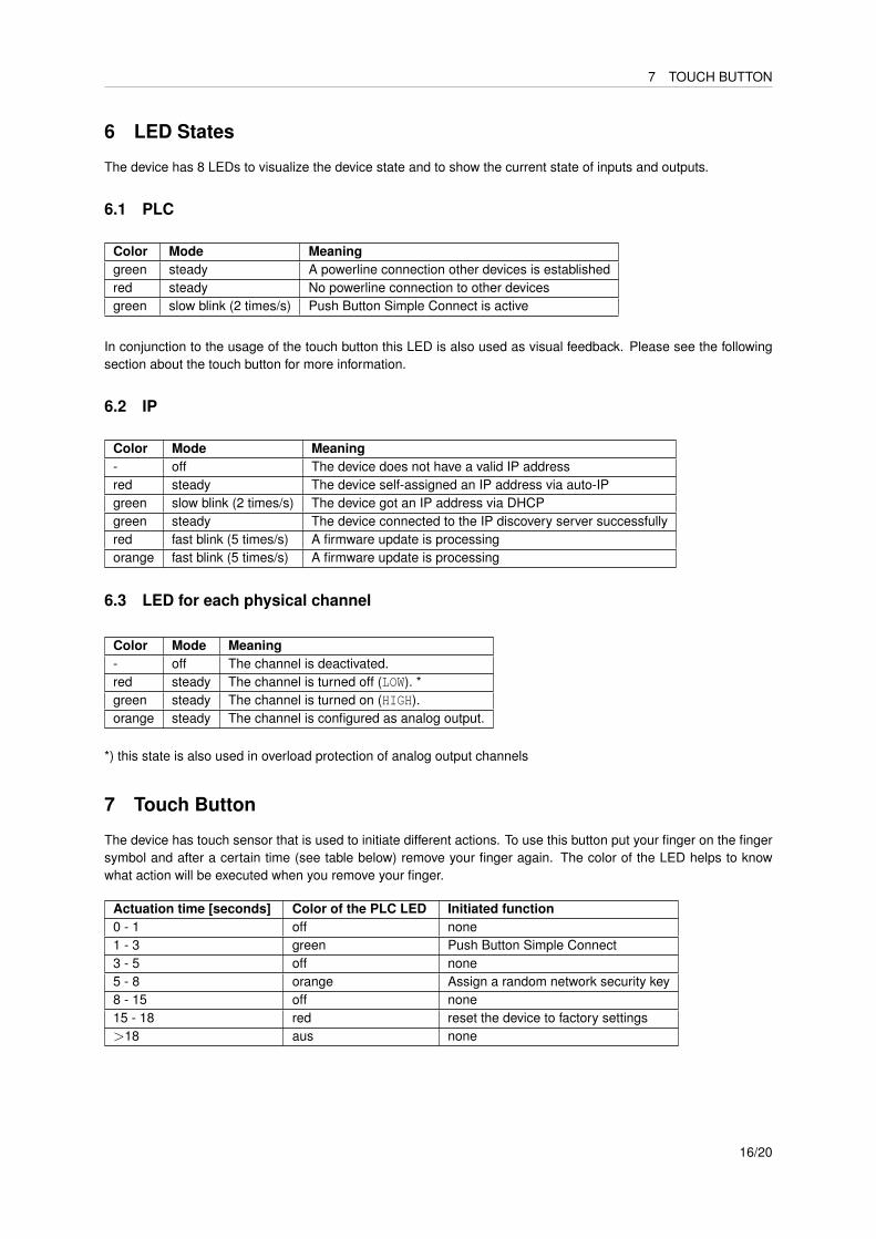
6 LED States
The device has 8 LEDs to visualize the device state and to show the current state of inputs and outputs.
6.1 PLC
Color Mode Meaninggreen steady A powerline connection other devices is establishedred steady No powerline connection to other devicesgreen slow blink (2 times/s) Push Button Simple Connect is active
In conjunction to the usage of the touch button this LED is also used as visual feedback. Please see the followingsection about the touch button for more information.
6.2 IP
Color Mode Meaning- off The device does not have a valid IP addressred steady The device self-assigned an IP address via auto-IPgreen slow blink (2 times/s) The device got an IP address via DHCPgreen steady The device connected to the IP discovery server successfullyred fast blink (5 times/s) A firmware update is processingorange fast blink (5 times/s) A firmware update is processing
6.3 LED for each physical channel
Color Mode Meaning- off The channel is deactivated.red steady The channel is turned off (LOW). *green steady The channel is turned on (HIGH).orange steady The channel is configured as analog output.
*) this state is also used in overload protection of analog output channels
7 Touch Button
The device has touch sensor that is used to initiate different actions. To use this button put your finger on the fingersymbol and after a certain time (see table below) remove your finger again. The color of the LED helps to knowwhat action will be executed when you remove your finger.
Actuation time [seconds] Color of the PLC LED Initiated function0 - 1 off none1 - 3 green Push Button Simple Connect3 - 5 off none5 - 8 orange Assign a random network security key8 - 15 off none15 - 18 red reset the device to factory settings>18 aus none
16/20

10 TECHNICAL DATA
8 Application Examples
Figure 8: Coniguration of physical channel 3 as digital output to completely power off the dimmable power supplythat is controlled by physical output 4 (analog output)
9 Maintenance and Cleaning
The device does not need maintenance. If it is defective and needs to be repaired send it back to your seller or themanufacturer.
10 Technical Data
All technical data is documented in the datasheet.
17/20

11 LEGAL NOTES
11 Legal Notes
11.1 Licenses
The device firmware includes software components with the following licenses:
Copyright : 1997 - 2014 Freescale Semiconductor, Inc.All Rights Reserved.
Redistribution and use in source and binary forms, with or without modification,are permitted provided that the following conditions are met:
o Redistributions of source code must retain the above copyright notice, this listof conditions and the following disclaimer.
o Redistributions in binary form must reproduce the above copyright notice, thislist of conditions and the following disclaimer in the documentation and/orother materials provided with the distribution.
o Neither the name of Freescale Semiconductor, Inc. nor the names of itscontributors may be used to endorse or promote products derived from thissoftware without specific prior written permission.
THIS SOFTWARE IS PROVIDED BY THE COPYRIGHT HOLDERS AND CONTRIBUTORS "AS IS" ANDANY EXPRESS OR IMPLIED WARRANTIES, INCLUDING, BUT NOT LIMITED TO, THE IMPLIEDWARRANTIES OF MERCHANTABILITY AND FITNESS FOR A PARTICULAR PURPOSE AREDISCLAIMED. IN NO EVENT SHALL THE COPYRIGHT HOLDER OR CONTRIBUTORS BE LIABLE FORANY DIRECT, INDIRECT, INCIDENTAL, SPECIAL, EXEMPLARY, OR CONSEQUENTIAL DAMAGES(INCLUDING, BUT NOT LIMITED TO, PROCUREMENT OF SUBSTITUTE GOODS OR SERVICES;LOSS OF USE, DATA, OR PROFITS; OR BUSINESS INTERRUPTION) HOWEVER CAUSED AND ONANY THEORY OF LIABILITY, WHETHER IN CONTRACT, STRICT LIABILITY, OR TORT(INCLUDING NEGLIGENCE OR OTHERWISE) ARISING IN ANY WAY OUT OF THE USE OF THISSOFTWARE, EVEN IF ADVISED OF THE POSSIBILITY OF SUCH DAMAGE.
http: www.freescale.commail: [email protected]
Copyright (c) 2001-2004 Swedish Institute of Computer Science.All rights reserved.
Redistribution and use in source and binary forms, with or without modification,are permitted provided that the following conditions are met:
1. Redistributions of source code must retain the above copyright notice,this list of conditions and the following disclaimer.
2. Redistributions in binary form must reproduce the above copyright notice,this list of conditions and the following disclaimer in the documentationand/or other materials provided with the distribution.
3. The name of the author may not be used to endorse or promote productsderived from this software without specific prior written permission.
THIS SOFTWARE IS PROVIDED BY THE AUTHOR ‘‘AS IS’’ AND ANY EXPRESS OR IMPLIEDWARRANTIES, INCLUDING, BUT NOT LIMITED TO, THE IMPLIED WARRANTIES OFMERCHANTABILITY AND FITNESS FOR A PARTICULAR PURPOSE ARE DISCLAIMED. IN NO EVENTSHALL THE AUTHOR BE LIABLE FOR ANY DIRECT, INDIRECT, INCIDENTAL, SPECIAL,EXEMPLARY, OR CONSEQUENTIAL DAMAGES (INCLUDING, BUT NOT LIMITED TO, PROCUREMENTOF SUBSTITUTE GOODS OR SERVICES; LOSS OF USE, DATA, OR PROFITS; OR BUSINESS
18/20

11.2 Disposal 11 LEGAL NOTES
INTERRUPTION) HOWEVER CAUSED AND ON ANY THEORY OF LIABILITY, WHETHER INCONTRACT, STRICT LIABILITY, OR TORT (INCLUDING NEGLIGENCE OR OTHERWISE) ARISINGIN ANY WAY OUT OF THE USE OF THIS SOFTWARE, EVEN IF ADVISED OF THE POSSIBILITYOF SUCH DAMAGE.
This file is part of the lwIP TCP/IP stack.
Author: Adam Dunkels <[email protected]>
11.2 Disposal
Do not dispose off the device in the domestic waste. Electronic devices need to be disposed off according to locallaws.
19/20