user manual - w&h
TRANSCRIPT

DemineralizerDemineralisierer
DemineralisateurDemineralizzatore
För fast vattenanslutningDemineralisaattoriDesmineralizador
Dem 32 - 201 10 REV. 4
User Manual
Dem 32
DEMINERALIZER
User Manual
DEMINERALISIERER Bedienungsanleitung
DEMINERALISATEURManuel d’utilisation
DEMINERALIZZATORE Manuale Utente
FÖR FAST VATTENANSLUTNINGBruksanvisning
DEMINERALISAATTORIKäyttöopas
DESMINERALIZADORManual del Usuario
Es
paño
l
Suom
i
Ita
liano
Fr
ança
is
D
euts
ch
En
glis
h
Sv
ensk
a

Dem 32 1
Eng
lish
Dem 32
DEMINERALIZER
USER MANUAL
Dear User, We would like to thank you for purchasing our demineralizer Dem 32. We are pleased to provide the following information concerning the use of this equipment. We remind you that in order to use the demineralizer correctly, it is necessary to read this manual carefully. All our products comply with the current safety norms and do not involve any risk for the operator when used according to the instructions provided. Whilst wishing you every success in your work, please note that the reproduction of this manual is illegal and that, owing to continuous research and technological development, the equipment specifications could change without prior notice.
W&H STERILIZATION S.r.l.

2 Dem 32
TABLE OF CONTENTS
INTRODUCTION......................................................................................................................................3
GENERAL RECOMMENDATIONS ..................................................................................................... 3 RESIN CARTRIDGES – SAFETY PRECAUTIONS............................................................................ 4 INFORMATION ON WARRANTY........................................................................................................ 5
PACKAGE CONTENTS..................................... ......................................................................................6
GENERAL NOTES ON DELIVERY..................................................................................................... 6 PACKAGE SIZE AND WEIGHT .......................................................................................................... 6 DELIVERY CONTENT......................................................................................................................... 7
INSTALLATION AND USE.................................. ....................................................................................8
SYMBOLS ON THE NAMEPLATE...................................................................................................... 8 MOUNTING OF THE RESIN CARTRIDGES ...................................................................................... 9 INSTALLATION ................................................................................................................................. 10 REPLACEMENT OF THE RESIN CARTRIDGES............................................................................. 12 PRECAUTIONS TO AVOID WATER CONTAMINATION ................................................................. 12 OPERATION OF THE DEMINERALIZER ......................................................................................... 12
MAINTENANCE......................................... ............................................................................................14
EXTERNAL CLEANING .................................................................................................................... 14 MAINTENANCE OF THE WATER BLOCK® SAFETY VALVE ......................................................... 14 REGULAR CHECK OF THE WATER BLOCK® AND ONE-WAY VALVES....................................... 14 SPARE PART LIST ........................................................................................................................... 15
TECHNICAL INFORMATION .................................. ..............................................................................16
MAINTENANCE INSTRUCTIONS FOR THE SAFETY VALVE (WATER BLOCK ®) ...........................17
Dem 32 3
Eng
lish
INTRODUCTION
This manual provides instructions for:
- Safe and efficient operation of the equipment - Correct installation
- Continuous and scheduled maintenance.
� The sizes mentioned in this manual are subject to change without notice.
� Drawings and any other documents delivered with the equipment belong to the manufacturer, who reserves all rights; they cannot be made available to third parties.
� The reproduction of texts or images used in this manual, either in total or in part, is illegal. GENERAL RECOMMENDATIONS • The equipment should be used in compliance with the procedures described in this manual and
never for other purposes.
• The user is responsible for installing, operating and servicing the equipment in accordance with the instructions listed in this manual.
• Only use genuine manufacturer resin cartridges dedicated for this product.
• Do not drink the water produced by Dem 32.
• Do not block or crush the inlet or outlet tubes of the equipment or the sterilizer.
• In case the equipment is not operated according to the instructions in this manual or is not properly maintained, the manufacturer cannot be held responsible for any fault, damage or malfunctioning of the equipment.
• When used in conjunction with a sterilizer, replace resin cartridges immediately once the water conductivity value exceeds 15-20 µS (warning message appears on most sterilizers) to avoid serious damage to the sterilizer.
• The demineralizer has been designed and tested to be connected directly to the tap water supply.
Connections to other water treatment systems e.g deionizer or water softener could lead to anomalies and or reduction of the cartridges lifespan.
Intended use : This manual is an integral part of the product and must be kept close to the equipment for easy and quick reference. The equipment is to be used only for the purpose for which it is designed. Dem 32: Device designed for the demineralization of drinking water and manual
or automated supply to steam sterilizers.

4 Dem 32
RESIN CARTRIDGES – SAFETY PRECAUTIONS
Contact Hazards
Eye contact Irritation of the eyes (R36).
Skin contact Slight irritation of the skin.
First Aid procedures
Skin contact Take off any contaminated clothes.
Remove resin beads and clean the affected area with water.
Eye contact Flush eyes immediately with large amounts of water and remove resin beads.
Precautions in case material is spilled
Precautions for people Keep people away from the area of spillage.
Resin beads on the floor may cause floor to be slippery. Take care not to slip.
Cleaning methods Sweep the floor and transfer resin beads to a plastic container for recovery or disposal according to the appropriate guidelines.
Notes for disposal
The used product is a special non hazardous waste. The product must be disposed of in accordance with current local, regional and country regulations. The CER number for saturated or used ion-exchange resins used for the production of drinking or service water is: 19 09 05.

Dem 32 5
Eng
lish
INFORMATION ON WARRANTY
The manufacturer grants warranty on your product, if used in accordance with the instructions described in this manual, for a period of 12 months for mechanical and electrical components. The warranty starts from the date of delivery to the customer, which must be proven by returning the warranty form duly filled in and signed. In case of dispute, the date on the delivery note relating to the equipment serial number will be valid. The warranty does not cover defects or damage caused by:
� Incorrect installation � Inadequate maintenance � Tampering or unauthorized modifications � Incorrect use of the equipment � Non-compliance with the instructions included in this manual
The replacement of equipment or the extension of the warranty period because of breakdown is excluded. Repair under warranty is carried out at judgment of the manufacturer and does not include packing and shipment costs.

6 Dem 32
PACKAGE CONTENTS
GENERAL NOTES ON DELIVERY
Upon delivery of the equipment, check the condition of the package and keep it in case of future needs. Open the package and check that:
- the contents correspond to the delivery note - there is no evidence of any damage.
In the event of damage or missing items, inform the carrier and the supplier immediately.
PACKAGE SIZE AND WEIGHT
Gross weight: 8,5 kg Dimensions (mm)

Dem 32 7
Eng
lish
DELIVERY CONTENT
Item Description
1. Demineralizer
2. 2 resin cartridges + 2 sealing rings
3. Special key to replace cartridges
4. Water feeding pipe with tap water fitting (4m, Ø 6x4 mm)
5. Water Block valve (including filter and setting key)
6. Water gun with spiral tube
7. Inlet tube (2 m, Ø ¼”)
8. Drain tube (3 m, 8x6 mm)
9. Interface cable
10. 2 angled connectors (1 for a tube Ø ¼” and 1 for a tube Ø 8x6 mm)
11. Screws and dowels for fixing the unit on a wall
12. Warranty certificate, declaration of conformity CE and user manual
1
2
3
4 5
7
8
9
10
12
11
6

8 Dem 32
INSTALLATION AND USE
SYMBOLS ON THE NAMEPLATE
Model name Serial number
Working pressure
Country of manufacture
Read the manual carefully
Product code Working voltage
Power consumption
Year
Serial number datamatrix
CE label
Manufacturer
Recycling symbol
The equipment is fitted with a protective mechanical device allowing only one-way water flow; in accordance with EN 1717

Dem 32 9
Eng
lish
MOUNTING OF THE RESIN CARTRIDGES
1. Remove the filter head cover.
2. Remove the tubes from the two quick connectors (IN/OUT) on the unit head and lift the entire cartridge assembly from the demineralizer base.
3. Unscrew the two resin cartridge holders (by hand or with the use of the special key).
4. Remove the cartridges’ bag and place them into the holders (with the cone-shaped side facing downwards and the word “UP” at the top).
5. Place the o-rings in the groove of the resin cartridge holders and tighten holders by hand (use only moderate force if you use the special key).
6. Place the cartridge assembly back into the demineralizer base and fix it into place with the use of the positioning rings.
7. Reconnect the tubes to the IN and OUT connectors (make sure that the IN connector is on the left hand side).
8. Attach the filter head cover.
IN
1
2
2
4
OUT
5
2
4
5
7

10 Dem 32
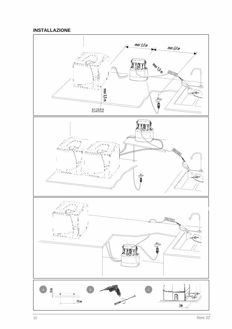
INSTALLATION
b c
a
a

Dem 32 11
Eng
lish
Manual use
Automated fill of sterilizer
WARNING Use only original spare parts. The Water Block® valve is fitted with a special one-way valve that prevents water from flowing back and potentially polluting the main waterline. For this reason the Water Block valve should be mounted vertically .
WARNING Check that all the tubes are connected correctly. Before connecting the tubes, check that they are correctly cut at 90° with no uncut parts.
1 2 3
Interface cable
Drain tube
Inlet tube
4 5

12 Dem 32
REPLACEMENT OF THE RESIN CARTRIDGES
When used with a sterilizer, replace the resin cartridges when the water conductivity reaches a value of 15 µS. Most sterilizers generate a display message once the water quality drops below this threshold.
1. Close the inlet tap
2. Release the pressure by using the spray gun (check that the spiral tube’s connecting tap is open during this operation).
3. Follow the steps as described in chapter “MOUNTING OF THE RESIN CARTRIDGES”.
4. Re-open the inlet tap.
PRECAUTIONS TO AVOID WATER CONTAMINATION
ATTENTION In accordance with EN1717, in order to avoid water quality degradation and bacterial growth due to a tailback of water in the tubes, the entire system must be drained before leaving it unused for a longer period of time.
OPERATION OF THE DEMINERALIZER Once installed and fitted correctly, the demineralizer is able to supply demineralized water immediately. As shown in the Installation section, the demineralizer can be used in two ways: Manual use : the water pistol can be used to manually fill the sterilizer water tank and also to rinse instruments;
Automatic use : 1 or 2 sterilizers that are suitable for use with the device ( see sterilizer user manual) can automatically be supplied. When the quantity of water in the sterilizer’s clean water tank is below the minimum levels, the sterilizer powers the external device (at 24Vdc) via the interface cable and water is automatically supplied to the sterilizer. During the filling of water, the sterilizer’s on board conductivity metre monitors the water conductivity. When the filter resins or the upstream treatment system are becoming over-consumed, the conductivity value increases and when the maximum level is reached a corresponding warning message is displayed on the sterilizer’s touch screen.

Dem 32 13
Eng
lish
The quantity of demineralized water produced per set of resin cartridges depends on the quality and hardness of the city water in your area. Refer to the table below for further details:
ATTENTION The demineralizer is equipped with a (Water Block®) safety valve that cuts off the water flow after a pre-adjusted volume (5 liters) in order to prevent a large spillage of water in case of a broken tube or connection. When you take water from the demineralizer with the use of the spray gun and the volume goes beyond 5 liters, the Water Block® valve will cut off the water supply. To reset the Water Block® valve see chapter “Maintenance instructions for the safety valve”. To avoid a water cutoff, release the water gun once every 30 seconds if quantities of more than 5 liters are taken from the demineralizer. WARNING The Water Block serves as an anti-flooding device. Blocking only takes place if there is considerable leakage (such as a cut in the tube between the Water Block and the demineralizer). Blocking does not take place if there is a small leak in the product’s hydraulic system.
WARNING It is recommended that the connection tap between the spray gun’s spiral tube and the Dem 32 be closed if the gun is not being used.
0
50
100
150
200
250
300
0 200 400 600 800 1000 1200
Conductivity of the tap water ( µS/cm )
Litre
s pr
oduc
ed

14 Dem 32
MAINTENANCE
EXTERNAL CLEANING
Clean with a damp cloth using non-abrasive and non-corrosive detergents (neutral pH value).
MAINTENANCE OF THE WATER BLOCK ® SAFETY VALVE The inlet filter of the Water Block® valve should be cleaned on a regular basis, depending on the city water quality and frequency of usage of the demineralizer.
REGULAR CHECK OF THE WATER BLOCK ® AND ONE-WAY VALVES
ATTENTION
To ensure compliance with EN1717, have the Water Block® and the one-way valve checked at least once a year; in case a sterilizer is attached to the demineralizer, this could be done during the scheduled maintenance visits for the sterilizer.
It is further recommended to check all related devices fitted to the steriliser to ensure that the hydraulic connection between demineralizer and sterilizer corresponds to category 2, in accordance with EN 1717.

Dem 32 15
Eng
lish
SPARE PART LIST
Nr. Description Code
1 FILTER HEAD COVER A812109X
2 FILTER HEAD A812104X
3 CARTRIDGE HOLDER A812103X
4 RESIN CARTRIDGE KIT (4 CARTRIDGES + 4 SEALING RINGS + 4 O-RINGS) A812100X
5 SPECIAL KEY FOR CARTRIDGE HOLDERS A812101X
6 WATER GUN A812106X
7 SPIRAL TUBE A812105X
8 TAP A812107X
9 WATER FEEDING PIPE WITH TAP WATER FITTING (4 m, Ø 6X4mm) A812102X
10 SAFETY VALVE (WATER BLOCK®) WITH FILTER AND ADJUSTING KEY A812005X
11 ONE WAY VALVE A812108X
12 O-RING A813014X
13 CENTERING RING A813006X
14 INLET TUBE Ø 1/4” (2 m) W230004X
15 DRAIN TUBE Ø 8x6mm (3 m) W230009X
16 ELECTRIC VALVE 24VDC U382016X
17 INTERFACE CABLE A812004X
18a FITTING FOR TUBE Ø ¼” W321213X
18b FITTING FOR TUBE Ø 8X6 mm W321212X
19 OPTIONAL - DRAIN TUBE MOUNTING KIT WITH T FITTING A812110X
20 OPTIONAL - SPIRAL TUBE EXTENSION (2 m) WITH FITTING A812111X
21 OPTIONAL –DEM 32 KIT FOR SECOND AUTOCLAVE A812115X
X 4

16 Dem 32
TECHNICAL INFORMATION
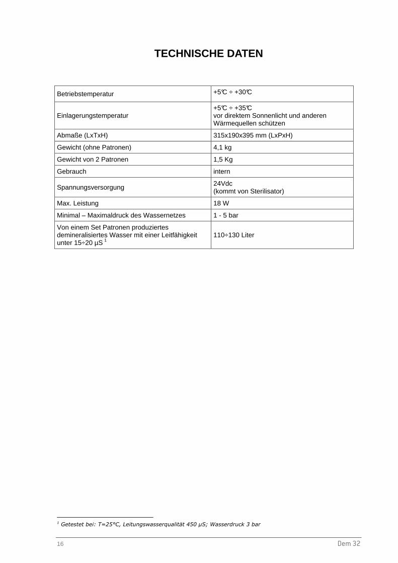
Operating temperature +5°C ÷ +30°C
Storage temperature +5°C ÷ +35°C avoid direct sunlight and all sources of heat
Size 315x190x395 mm (WxDxH)
Weight (without cartridges) 4.1 kg
Weight of 2 cartridges 1.5 kg
Use internal
Working voltage 24Vdc (powered by sterilizer)
Maximum power consumption 18 W
Inlet tap water pressure range 1 - 5 bar
Amount of demineralized water produced with one set of cartridges with a conductivity value lower than 15÷20 µS 1
110÷130 liters
1 Tested at: T=25°C; tap water quality 450 µS; water pressure 3 bar

Dem 32 17
Eng
lish
MAINTENANCE INSTRUCTIONS FOR THE SAFETY VALVE (WATER BLOCK ®)
WATER BLOCK (WB) SAFETY VALVE Indispensable device for washing machines, dishwashers and demineralizers as, under the conditions defined in the technical features described below, it prevents a flow of water greater than that for which it has been set by the adjustment pointer. This avoids continuous leaking. The Water Block also has a special non-return valve (antipollution). The device should be installed vertically (see fig. 2) and following the instructions carefully. TECHNICAL FEATURES
- Burst pressure: 500 N/cm²
- Max. static pressure: 100 N/cm²
- Max. controllable volume: about 50 lt.
- Min. operating capacity: 2 lt/min.
- Max. operating capacity: 30 lt/min
- Max. water temperature: 70° C
USER INSTRUCTIONS WATER BLOCK should be installed between the tap and the supply hose of the demineralizer (fig. 2). Using the enclosed plastic key, turn pointer ‘P’ (fig. 1) anticlockwise to the required setting (example, position 1,5). CAUTION: For use on other fixtures, set the pointer to a position suitable for that particular application, considering that each number on the scale corresponds to a controlled volume of approx. 4-6 litres. In case of installation on fixtures which foresee dispensing of drinking water for alimentary use it is advisable to let flow at least 10 litres of water inside the device before the connection, so as remove eventual impurities banked during the storage. INSTALLATION 1. Manually screw the WB to the tap having suitable thread (3/4” gas),
inserting the filter ‘E’ with its convex side facing upwards (fig. 2). The WB will not operate properly if the filter is not installed correctly. If the WB is tightened or loosened with the aid of a wrench, the same must be applied to the appropriately octagonally shaped part of the housing ‘A’.
2. Screw the supply hose ‘C’ to the lower end of the WB. If the supply hose is equipped with a filter, the latter must be substituted by a flat rubber washer ‘F’. If the said hose has to be tightened or loosened with the aid of a wrench, the same must be applied to the appropriately octagonally shaped part of the WB housing ‘B’ so as to hold it firmly while performing this operation. If a failure occurs causing a continuous water leak, the WB will shut off when the volume of water flowing through equals the amount to which it was previously set with the pointer ‘P’. To reset the Water Block again after it has shut off, turn the tap off and carry out the necessary repair work. Remove the supply hose ‘C’ from the Water Block and press the coloured plunger ‘H’ which is located inside the lower housing of the device itself (fig. 1). It may be difficult to press this plunger if there is high pressure at the inlet side of the WB. In this case, slacken the device from the tap: the plunger ‘H’ can then be pressed with ease. Repeat the operation as described in the section headed ‘Installation’.
CAUTION: To avoid any possible damage that may be caused by water freezing inside the WB after its installation, the ambient temperature should never be below 2° C. We decline all responsibility deriving from the incorrect use of the WB or from its use for applications and/or solutions not expressly foreseen by the above instructions. MAINTENANCE: Depending on the conditions and frequency of usage of the water block, it is recommended to clean out the inlet filter ‘E’ periodically and to replace the seal ‘F’.We reserve the right to modify any features without prior notice.
Fig. 1
Produced by ELTEK s.p.a. Tel. 0142 335511 Fax 0142 335555 15033 Casale Monf. (Italy) [email protected]

Dem 32 1
Deu
tsch
Dem 32
DEMINERALISIERER
BEDIENUNGSANLEITUNG
Sehr geehrte/r Frau/Herr Doktor, Sie haben den Dem 32 Demineralisierer gekauft – herzlichen Dank für Ihr Vertrauen in unser Produkt! Der Hersteller steht für Fragen betreffend Dem 32 Demineralisierer jederzeit gerne zur Verfügung. Ebenso möchten wir betonen, dass es für eine korrekte Benutzung des Demineralisierers Dem 32 unbedingt notwendig ist, diese Bedienungsanleitung aufmerksam zu lesen. Unsere Produkte erfüllen die generell gültigen Vorschriften über Sicherheit und sie stellen keine Gefahr für den Benutzer dar, wenn sie gemäß den angeführten Anweisungen benutzt werden. Wir wünschen Ihnen eine erfolgreiche Verwendung und weisen Sie darauf hin, dass die Reproduktion dieser Bedienungsanleitung verboten ist. Wir behalten uns technische Änderungen vor.
W&H STERILIZATION S.r.l.

2 Dem 32
INHALTSVERZEICHNIS
EINLEITUNG............................................................................................................................................3
GENERELLE EMPFEHLUNGEN ........................................................................................................ 3 ALLGEMEINE SICHERHEITSHINWEISE........................................................................................... 4 HINWEISE ZUR GARANTIE ............................................................................................................... 5
LIEFERUNG.............................................................................................................................................6
GENERELLE HINWEISE ZUR LIEFERUNG ...................................................................................... 6 GRÖSSE UND GEWICHT DER VERPACKUNG................................................................................ 6 LIEFERUMFANG................................................................................................................................. 7
INSTALLATION UND GEBRAUCH ............................. ...........................................................................8
BEDEUTUNG DER SYMBOLE DES TYPENSCHILDES ................................................................... 8 MONTAGE DER HARZPATRONEN ................................................................................................... 9 INSTALLATION ................................................................................................................................. 10 WECHSELN DER HARZPATRONEN............................................................................................... 12 VORBEUGENDE MASSNAHMEN BEI LÄNGEREN STANDZEITEN.............................................. 12 BETRIEB DES DEMINERALISIERERS ............................................................................................ 12
INSTANDHALTUNG........................................ ......................................................................................14
EXTERNE REINIGUNG .................................................................................................................... 14 INSTANDHALTUNG DES SICHERHEITSVENTILS (Water Block®) ................................................ 14 REGELMÄSSIGE KONTROLLE DER RÜCKLAUF-VORRICHTUNGEN......................................... 14 ERSTATZTEILE ................................................................................................................................ 15
TECHNISCHE DATEN...........................................................................................................................16
SICHERHEITSVENTIL (WATER BLOCK®) BEDIENUNGSANLEITUNG..... ......................................17

Dem 32 3
Deu
tsch
EINLEITUNG Dieses Handbuch gibt Ihnen Informationen und Anweisungen über:
- die sichere und effiziente Benutzung des Dem 32 Demineralisierers
- die kontinuierliche und regelmäßige Wartung. - die korrekte Installation
� Alle Größen, die im Handbuch spezifiziert werden, sind unverbindlich.
� Die in dieser Bedienungsanleitung enthaltenen Zeichnungen und Dokumente gehören dem Hersteller der sich alle Rechte vorbehält. Sie dürfen Dritten nicht zur Verfügung gestellt werden.
� Der Nachdruck von Text oder Abbildungen aus dieser Bedienungsanleitung ist verboten.
GENERELLE EMPFEHLUNGEN • Der Dem 32 Demineralisierer ist ausschließlich für die in dieser Bedienungsanleitung enthaltene
Zweckbestimmung einzusetzen.
• Der Benutzer ist für die korrekte Installation, die richtige Benutzung und die regelmäßige Wartung des Apparats verantwortlich.
• Benutzen Sie nur original Harzpatronen.
• Das vom Dem 32 Demineralisierer produzierte Wasser ist nicht als Trinkwasser geeignet.
• Achten Sie darauf die Zu- und Abwasserschläuche bei der Montage und während des Betriebes nicht zu beschädigen.
• Bei Nichtbeachtung der Installations-, Bedienungs- und Wartungsbeschreibungen wie aufgeführt in dieser Bedienungsanleitung, erlischt jeglicher Garantie- und Regressanspruch.
• Wird der Dem 32 Demineralisierer zum Befüllen von Sterilisatoren verwendet, sollten umgehend die Harzpatronen getauscht werden sobald die Wasserqualität den Wert von 15-20µS/cm übersteigt, da ansonsten die Sterilisatoren schwer beschädigt werden können.
• Dem 32 wurde für den direkten Anschluss an das Festwasser entwickelt und getestet.
Durch einen indirekten Anschluss über Wasseraufbereitungsanlagen wie z.B. Entsalzungs- oder anderen Wasserenthärtungsanlagen kann es zu Störungen kommen und / oder zu einer Reduzierung der Lebensdauer der Harzpatronen führen.
Diese Bedienungsanleitung ist ein integraler Bestandteil des Produktes und soll in der Nähe des Apparats aufbewahrt werden, um einfach und schnell als Referenz zur Verfügung zu stehen. Dem 32: Gerät für das Demineralisieren von Leitungswasser und die manuelle
oder automatische Wasserzufuhr an Sterilisatoren.

4 Dem 32
ALLGEMEINE SICHERHEITSHINWEISE
Gefahren durch Kontakt der Harze
Augenkontakt Reizung der Augen (R36).
Hautkontakt Leichte Reizung der Haut.
Erste Hilfe - Maßnahmen
Augenkontakt Mit sauberem Wasser ausspülen und dabei vorsichtig die Harzkristalle entfernen.
Hautkontakt Verschmutzte Bekleidung ausziehen. Harzkristalle entfernen, und die betroffene Stelle mit sauberem Wasser ausspülen.
Vorsichtsmaßnahmen bei auslaufendem Wasser oder verschütteten Harzkristallen
Allgemeine Vorsichtsmaßnahmen Um Unfälle (Sturz) bei ausgelaufenem Wasser oder Harzkristallen zu vermeiden, sollte die Stelle vorsichtig gereinigt werden, da erhöhte Rutschgefahr durch das Wasser bzw. die Harzkristalle besteht.
Reinigung Den Boden aufwischen und die vom Wasser getränkten Harzkristalle in einem Behälter für eine eventuelle Wiederver-wendung aufbewahren, oder entsorgen.
Bemerkungen für die Entsorgung der Harze (Harzpatronen)
Gebrauchte Harzpatronen sind ein nicht gefährlicher Sondermüll. Sie müssen nach den lokalen, regionalen und staatlichen Vorschriften entsorgt werden.
Die CER Nummer für durchnässte oder gebrauchte Ionenaustauschharze, die für die Produktion von Trink – oder demineralisiertem Wasser bestimmt sind, lautet: 19 09 05.

Dem 32 5
Deu
tsch
HINWEISE ZUR GARANTIE Der Hersteller gewährt für dieses Gerät eine Garantie von 12 Monaten auf mechanische und elektronische Teile, wenn die in dieser Bedienungsanleitung beschriebenen Anweisungen befolgt werden. Die Garantie beginnt mit dem Auslieferungsdatum an den Kunden und durch die Rückgabe der ausgefüllten Garantiekarte. Im Falle eines Streitfalles, ist das Datum auf dem Lieferschein für das betreffende Gerät gültig. Der Hersteller kann keine Garantie gewähren bei:
■ fehlerhafter Installation ■ unangemessener Wartung ■ Manipulation oder nicht autorisierten Änderungen ■ unkorrekter Benutzung des Dem 32 ■ Nichteinhaltung der in dieser Bedienungsanleitung enthaltenen Anweisungen
Ein Austausch des Dem 32 während der Garantiezeit sowie eine Verlängerung der Garantie sind ausgeschlossen. Die Reparatur unter Garantie wird nach Beurteilung des Herstellers durchgeführt und schließt die Verpackungs- und Transportkosten nicht ein.

6 Dem 32
LIEFERUNG
GENERELLE HINWEISE ZUR LIEFERUNG Kontrollieren Sie bitte beim Eingang des Produktes die Verpackung auf Unversehrtheit und bewahren Sie diese für eventuelle Versendungen auf. Öffnen Sie die Verpackung und kontrollieren Sie, dass
- die Lieferung dem Begleitschein entspricht; - es keine offensichtlichen Beschädigungen gibt.
Wenn die Lieferung beschädigt ist oder Teile fehlen, informieren Sie unmittelbar Ihren Spediteur, Ihr Dentaldepot oder den Hersteller. GRÖSSE UND GEWICHT DER VERPACKUNG Bruttogewicht: 8,5 Kg Größen in mm

Dem 32 7
Deu
tsch
LIEFERUMFANG
Nr. Beschreibung 1. Demineralisierer
2. 2 Stück Harzpatronen + Dichtungsringe
3. Schlüssel für das Auswechseln der Harzpatronen
4. Wasserschlauch mit Hahnansatz (4m, Ø 6x4 mm)
5. Sicherheitsventil (Water Block) mit Filter und Stellschlüssel
6. Spiralschlauch mit Sprühpistole
7. Eingangsschlauch (2 m, Ø ¼”)
8. Ablassschlauch (3 m, 8x6 mm)
9. Schnittstellenkabel
10. 2 Stück Verbindungselemente (1 für Ø ¼” Schlauch, 1 für Ø 8x6 mm Schlauch)
11. Schrauben und Dübel zum Fixieren an der Wand
12. Garantiezertifikat, Konformitätserklärung CE und Bedienungsanleitung
1
2
3
4 5
7
8
9
10
12
11
6

8 Dem 32
INSTALLATION UND GEBRAUCH
BEDEUTUNG DER SYMBOLE DES TYPENSCHILDES
Name des Produktes SN
Druckbereich des Leitungswassers
Herstellungsland
Gebrauchsanweisung sorgfältig lesen
Produkt-Code Spannung
Leistung
SN datamatrix
CE Symbol
Hersteller
Recycling Symbol
Gerät ist mit mechanischen Teilen ausgestattet, welche die Flussrichtung des Wassers nur in eine Richtung erlauben; gemäß Norm EN 1717

Dem 32 9
Deu
tsch
MONTAGE DER HARZPATRONEN
1. Entfernen Sie die Kopfabdeckung.
2. Entfernen Sie die beiden Wasserschläuche vom Einheitenkopf (IN/OUT) und heben Sie die ganze Kopfbaugruppe nach oben ab.
3. Schrauben Sie die beiden Patronenhalter mit der Hand oder mit Hilfe des Spezialschlüssels ab.
4. Entfernen Sie die Plastikverpackung der Harzpatronen und geben Sie die neuen Harzpatronen mit der konischen Seite nach unten in die Patronenhalter, mit der Aufschrift “UP” nach oben.
5. Setzen Sie die Dichtungsringe in die dafür vorgesehenen Nuten im oberen Bereich der Patronenhalter und schrauben Sie die Halter mit der Hand wieder fest.
6. Schieben Sie die beiden Positionierringe and den Patronenhaltern hoch und setzen Sie die Kopfbaugruppe wieder in die Einheitenbasis ein.
7. Schließen Sie nun die beiden Wasserschläuche wieder an (Achtung: IN Verbindung links; OUT Verbindung rechts).
8. Geben Sie die Kopfabdeckung wieder auf das Gerät.
IN
1
2
2
4
OUT
5
2
4
5
7
10 Dem 32
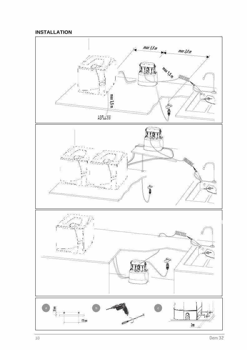
INSTALLATION
a b c
a

Dem 32 11
Deu
tsch
Manuelle Nutzung
Automatische Befüllung eines Sterilisators
ACHTUNG Benutzen Sie ausschließlich Originalersatzteile. Das Sicherheitsventil (Water Block®) ist mit einem Einwegventil ausgestattet, welches den Rückfluss von Flüssigkeiten in das Wasserversorgungsnetz und somit auch eine mögliche Verunreinigung verhindert. Zu diesem Zweck muss das Sicherheitsventil senkrecht eingebaut werden.
ACHTUNG Darauf achten, dass alle Schläuche gut angeschlossen sind. Bevor die Schläuche angeschlossen werden, stets darauf achten dass sie schön rechtwinkelig abgeschnitten (gekürzt) werden.
Schnittstellenkabel
Ablassschlauch
Eingangsschlauch
1 2 3
4 5

12 Dem 32
WECHSELN DER HARZPATRONEN Falls Sie das demineralisierte Wasser für einen Sterilisator verwenden, sollten Sie die Harzpatronen umgehend austauschen, sobald die Wasserqualität einen Wert (Wasserleitfähigkeit) von 15-20 µS erreicht hat.
1. Schließen Sie den Wasserhahn
2. Den Druck im System durch Betätigen der Sprühpistole entlasten
3. Führen Sie alle Schritte durch wie erwähnt im Kapitel “MONTAGE DER HARZPATRONEN”.
4. Der Wasserhahn kann wieder geöffnet werden
VORBEUGENDE MASSNAHMEN BEI LÄNGEREN STANDZEITEN
ACHTUNG Nach den Anforderungen der europäischen Norm EN 1717, sollte das im System verbleibende Wasser entleert werden, falls es für einen längeren Zeitraum nicht benutzt wird um eine Vermehrung der Bakterien durch stehendes Wasser in den Schläuchen und im Demineralisierer zu vermeiden.
BETRIEB DES DEMINERALISIERERS Nach der ordnungsgemäßen Installation des Demineralisierers, kann dieser sofort demineralisiertes Wasser liefern. Wie im Installationsblatt angezeigt, kann LisaDem32 für 2 verschiedene Varianten genutzt werden:
Manuell: Die Sprühpistole kann zum manuellen Befüllen eines Sterilisators oder zum Spülen von Instrumenten benützt werden. Automatisch: Es können gleichzeitig 1 oder 2 Sterilisatoren betrieben und mit demineralisiertem Wasser versorgt werden. Der Sterilisator überprüft bei jeder Aktivierung des LisaDem32 die Wasserqualität und gewährleistet somit einen sicheren Betrieb. Bei schlechter Wasserqualität wird dies sofort am Touch Screen angezeigt.
Dem 32 13
Deu
tsch
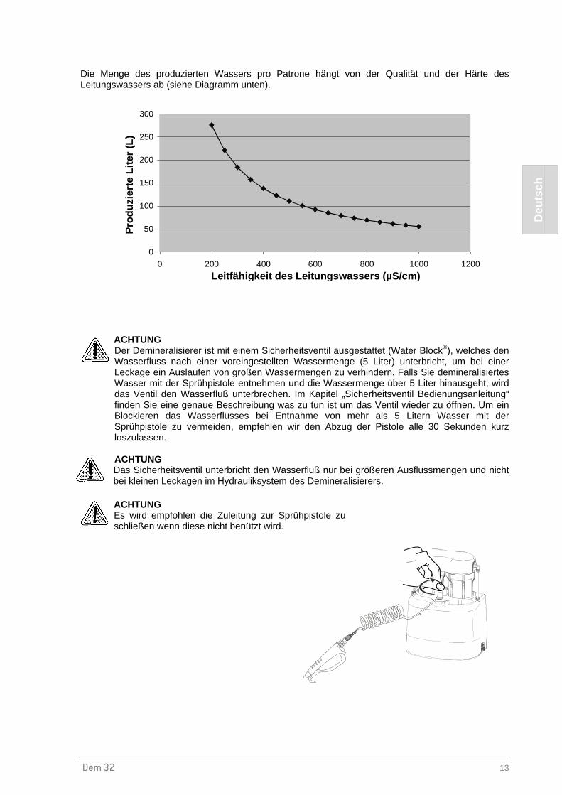
Die Menge des produzierten Wassers pro Patrone hängt von der Qualität und der Härte des Leitungswassers ab (siehe Diagramm unten).
ACHTUNG Der Demineralisierer ist mit einem Sicherheitsventil ausgestattet (Water Block®), welches den Wasserfluss nach einer voreingestellten Wassermenge (5 Liter) unterbricht, um bei einer Leckage ein Auslaufen von großen Wassermengen zu verhindern. Falls Sie demineralisiertes Wasser mit der Sprühpistole entnehmen und die Wassermenge über 5 Liter hinausgeht, wird das Ventil den Wasserfluß unterbrechen. Im Kapitel „Sicherheitsventil Bedienungsanleitung“ finden Sie eine genaue Beschreibung was zu tun ist um das Ventil wieder zu öffnen. Um ein Blockieren das Wasserflusses bei Entnahme von mehr als 5 Litern Wasser mit der Sprühpistole zu vermeiden, empfehlen wir den Abzug der Pistole alle 30 Sekunden kurz loszulassen. ACHTUNG Das Sicherheitsventil unterbricht den Wasserfluß nur bei größeren Ausflussmengen und nicht bei kleinen Leckagen im Hydrauliksystem des Demineralisierers.
ACHTUNG Es wird empfohlen die Zuleitung zur Sprühpistole zu schließen wenn diese nicht benützt wird.
0
50
100
150
200
250
300
0 200 400 600 800 1000 1200
Leitfähigkeit des Leitungswassers (µS/cm)
Pro
duzi
erte
Lite
r(L
)

14 Dem 32
INSTANDHALTUNG
EXTERNE REINIGUNG Reinigen Sie den Kopf des Demineralisators mit einem feuchten Tuch und einem neutralen Reinigungsmittel (neutraler pH-Wert). INSTANDHALTUNG DES SICHERHEITSVENTILS (Water Block ®) Der Einlassfilter des Water Blocks® sollte regelmäßig gereinigt wrden, abhängig von der Wasserqualität und der Häufigkeit der Nutzung des Demineralisierers. REGELMÄSSIGE KONTROLLE DER RÜCKLAUF-VORRICHTUNGEN
ACHTUNG
Um die Konformität mit der Norm EN1717 zu bewahren, müssen diese Vorrichtungen (Waterblock und Rückschlagventil) mindestens einmal im Jahr kontrolliert werden; ggf. bei den Wartungseingriffen des Kundendienstes für den Sterilisator.
Des Weiteren wird empfohlen, eventuelle weitere im Sterilisator vorhandenen Vorrichtungen zu überprüfen, damit am Hydraulikanschluss zwischen Demineralisierungsanlage und Sterilisator immer mindestens der in der EN 1717 vorgegebenen Flüssigkeitskategorie 2 entsprochen wird.

Dem 32 15
Deu
tsch
ERSTATZTEILE
Nr. Beschreibung Code
1 KOPFABDECKUNG A812109X
2 FILTERKOPF A812104X
3 PATRONENHALTER A812103X
4 PATRONENSATZ (4 HARZPATRONEN + 4 DICHTUNGSRINGE + 4 O-RINGE) A812100X
5 SPEZIALSCHLÜSSEL FÜR PATRONENHALTER A812101X
6 SPRÜHPISTOLE A812106X
7 SPIRALSCHLAUCH A812105X
8 WASSERHAHN A812107X
9 WASSERSCHLAUCH MIT ANSCHLÜSSEN (4 m, Ø 6X4mm) A812102X
10 SICHERHEITSVENTIL (WATER BLOCK®) MIT FILTER UND SPEZIALSCHLÜSSEL A812005X
11 EINWEGVENTIL A812108X
12 O-RING A813014X
13 ZENTRIERRING A813006X
14 EINGANGSSCHLAUCH Ø 1/4” (2 m) W230004X
15 ABLASSSCHLAUCH Ø 8x6mm (3 m) W230009X
16 ELEKTRISCHES VENTIL 24VDC U382016X
17 SCHNITTSTELLENKABEL A812004X
18a ANSCHLUSSSTÜCK FÜR Ø ¼” SCHLAUCH W321213X
18b ANSCHLUSSSTÜCK FÜR Ø 8X6 mm SCHLAUCH W321212X
19 OPTIONAL – MONTAGEKIT FÜR ABLASSSCHLAUCH MIT T-STÜCK A812110X
20 OPTIONAL – VERLÄNGERUNGSSCHLAUCH (2 m) MIT ANSCHLUSSTEIL A812111X
21 OPTIONAL – DEM 32 SATZ ZUM ANSCHLUSS EINES ZWEITEN AUTOKLAVEN A812115X
X 4
16 Dem 32
TECHNISCHE DATEN
Betriebstemperatur +5°C ÷ +30°C
Einlagerungstemperatur +5°C ÷ +35°C vor direktem Sonnenlicht und anderen Wärmequellen schützen
Abmaße (LxTxH) 315x190x395 mm (LxPxH)
Gewicht (ohne Patronen) 4,1 kg
Gewicht von 2 Patronen 1,5 Kg
Gebrauch intern
Spannungsversorgung 24Vdc (kommt von Sterilisator)
Max. Leistung 18 W
Minimal – Maximaldruck des Wassernetzes 1 - 5 bar
Von einem Set Patronen produziertes demineralisiertes Wasser mit einer Leitfähigkeit unter 15÷20 µS 1
110÷130 Liter
1 Getestet bei: T=25°C, Leitungswasserqualität 450 µS; Wasserdruck 3 bar

Dem 32 17
Deu
tsch
SICHERHEITSVENTIL (WATER BLOCK®) BEDIENUNGSANLEITUNG
SICHERHEITSVENTIL WATER BLOCK (WB) Dies ist ein unentbehrliches Zubehör für Wasch- und Geschirrspülmaschinen sowie Demineralisatoren. Wie in den technischen Eigenschaften beschrieben wurde, soll im Folgendem das Durchlaufen von größeren Wassermengen als auf dem Anzeiger eingestellt vermieden werden, wodurch ständiges Überlaufen verhindert wird. Das Gerät verfügt außerdem über ein spezielles Rückschlagventil (schützt vor Wasserverschmutzung). Für eine optimale Funktionsweise wird geraten, die Montage in vertikaler Position durchzuführen, wie in Abb. 2 dargestellt, wobei die folgenden Angaben sorgfältig eingehalten werden müssen. TECHNISCHE EIGENSCHAFTEN - Platzdruck: 500 N/cm² - max. statischer Druck: 100 N/cm² - max. kontrollierte Wasserdurchflussmenge: 50 l ca. - min. Durchflußmenge: 2 l/min. - max. Durchflußmenge: 30 l/min. - max. Wassertemperatur: 70° C MONTAGEANLEITUNG Der WATER BLOCK wird zwischen den Wasserhahn und dem Zulaufschlauch des Haushaltsgerätes (Abb. 2) montiert. Unter Zuhilfenahme des mitgelieferten Schlüssels wird der Anzeiger P im entgegengesetzten Uhrzeigersinn so lange gedreht bis die gewünschte Position erreicht wird. Bei Waschmaschinen wird der Anzeiger P auf die Nr. 8 voreingestellt (Abb. 1), während bei Anwendung auf Geschirrspülmaschinen der Anzeiger P auf die Nr. 1.5 gestellt wird (Abb. 1). ACHTUNG: Bei Einsatz auf anderen Geräten wird der Anzeiger auf die, der Anwendung entsprechend geeigneten Position gestellt, wobei zu beachten ist, daß jede Zahlenangabe auf der Skala einem kontrollierten Volumen von 4 bis 6 Litern Wasser entspricht. Bei Installation auf Getränkeautomaten und Trinkwasserspendern wird zur Entfernung von etwaigen, während der Lagerung angesammelten, Verschmutzungen im Gerät empfohlen, das Netzwasser mindesten 10 Minuten lang durch das Gerät laufen zu lassen. EINBAU 1. Den WATER BLOCK manuell am Wasserhahn (3/4” Gas) anschrauben, wobei
das Sieb E mit der Wölbung nach oben wie in Abb. 2 dargestellt eingelegt wird. Eine falsche Montage des Siebs verhindert eine korrekte Funktionsweise des WATER BLOCKS. Im Falle von An- und Abschrauben mit Werkzeugen muß das entsprechende Achteck A benutzt werden.
2. Der Wasserzulaufschlauch C wird an der unteren Seite des WATER BLOCKS
angeschraubt. Wenn der Wasserzulaufschlauch ein Sieb beinhaltet, muß dieses vorher entfernt und durch eine Flachdichtung F ersetzt werden. Im Falle von An- und Abschrauben mit Werkzeugen muß das entsprechende Sechseck B zur Blockierung des WATER BLOCKS während des Arbeitsgangs benutzt werden. Im Falle eines Defekts, der ein ständiges Wasserleck hervorruft, schließt der WATER BLOCK im Anschluß den Durchfluß der Wassermenge die vorher auf dem Anzeiger P eingestellt wurde. Zur Wiederherstellung der Funktion des WATER BLOCKS nach Auslösung des Blockiersystems wird der Wasserhahn geschlossen und der Defekt behoben. Dann wird der Wasserzulaufschlauch C vom WATER BLOCK abgeschraubt und der Stift H gedrückt, der sich auf der Unterseite des Gerätes (Abb. 1) befindet. Wenn der Wassereingangsdruck hoch ist kann es passieren, daß der Knopf schwer zu drücken ist. In diesem Fall wird der WATER BLOCK leicht vom Wasserhahn abgeschraubt. Der Knopf H kann ganz leicht eingedrückt werden. Daraufhin werden die Arbeitsgänge unter dem Kapitel Einbau wiederholt.
HINWEISE: Um möglichen Beschädigungen durch Gefrierung des Wasser im WATER BLOCK nach der Installierung vorzubeugen, darf die Umgebungstemperatur nie unter 2° C sinken. Wir lehnen jegliche Verantwortung / Haftung für unsachgemäße, falsche oder im folgendem nicht ausdrücklich aufgeführte Anwendung des Gerätes ab. WARTUNG: Aufgrund der äußeren Bedingungen und der Benutzungshäufigkeit wird empfohlen von Zeit zu Zeit das Eingangssieb E zu reinigen und die Dichtung F auszuwechseln. Wir behalten uns vor, die technischen Eigenschaften ohne Voranmeldung zu ändern.
Abb. 1
Abb. 2
Produced by ELTEK s.p.a. Tel. 0142 335511 Fax 0142 335555 15033 Casale Monf. (Italy) [email protected]

Dem 32 1
Fra
nçai
s
Dem 32
DEMINERALISATEUR
MANUEL D'UTILISATION
Cher Docteur, Nous voulons avant tout vous remercier pour la confiance que vous nous avez accordée en achetant notre appareil Dem 32. Le fabricant est à votre entière disposition pour vous fournir toute information complémentaire concernant votre équipement. Nous vous informons qu’il est nécessaire au préalable, de lire attentivement ce mode d’emploi pour l'installation et l'utilisation correcte de l’appareil. Tous nos produits sont conformes aux normes de sécurité en vigueur et ne présentent aucun risque pour l’utilisateur s’ils sont utilisés conformément aux instructions fournies. Nous vous rappelons également que la reproduction de ce manuel est formellement interdite et que, étant constamment à la recherche d'améliorations, nous nous réservons le droit de modifier les caractéristiques techniques de l’appareil sans préavis.
W&H STERILIZATION S.r.l.

2 Dem 32
SOMMAIRE
INTRODUCTION......................................................................................................................................3
RECOMMANDATION GÉNÉRALE ..................................................................................................... 3 RESINES – MESURES DE SECURITE.............................................................................................. 4 INFORMATION SUR LA GARANTIE .................................................................................................. 5
VERIFICATION A LA LIVRAISON........................... ...............................................................................6
RECOMMANDATIONS ....................................................................................................................... 6 DIMENSIONS ET POIDS DU COLIS .................................................................................................. 6 LISTE DES COMPOSANTS................................................................................................................ 7
INSTALLATION ET UTILISATION DE L’APPAREIL ................. ............................................................8
SIGNIFICATION DES SYMBOLES ET DONNÉES DE LA PLAQUE SIGNALÉTIQUE ..................... 8 MISE EN PLACE DES CARTOUCHES DE RESINE.......................................................................... 9 INSTALLATION ................................................................................................................................. 10 REMPLACEMENT DE LA CARTOUCHE DE RESINE..................................................................... 12 MESURE DE PREVENTION EN CAS D'ARRET PROLONGE ........................................................ 12 FONCTIONNEMENT DE L’APPAREIL ............................................................................................. 12
ENTRETIEN ...........................................................................................................................................14
NETTOYAGE EXTERNE................................................................................................................... 14 ENTRETIEN DE LA VANNE DE SECURITE WATER BLOCK® ....................................................... 14 CONTROLE PERIODIQUE DES SYSTEMES ANTI-REFLUX ......................................................... 14 PIÈCES DE RECHANGE .................................................................................................................. 15
CARACTERISTIQUES TECHNIQUES........................... .......................................................................16
INSTRUCTIONS DE MAINTENANCE DE LA VANNE DE SECURITE (WATE R BLOCK ®) ...............17

Dem 32 3
Fra
nçai
s
INTRODUCTION
Ce mode d'emploi fournit les informations nécessaires afin de vous garantir :
- une installation correcte - une utilisation sûre et optimale de l'équipement
- un entretien régulier et efficace.
� Dimensions non contractuelles
� Les schémas et tous les autres documents fournis avec l'équipement appartiennent au fabricant qui se réserve tous les droits et ne peuvent être mis à la disposition de tiers.
� La reproduction en tout ou partie du texte et des illustrations est interdite RECOMMANDATION GÉNÉRALE • L'équipement doit être utilisé conformément aux recommandations de ce manuel et jamais pour
d'autres utilisations non indiquées dans le manuel.
• L’utilisateur est responsable de l’installation, de l’utilisation et de l’entretien régulier de l’appareil décrits dans le manuel.
• Utiliser exclusivement les cartouches de résine originales.
• Ne pas boire l'eau produite par le Dem 32.
• Ne pas obstruer ni écraser le tuyau d'alimentation en eau courante.
• Si l'équipement n'est pas utilisé correctement ou si l'entretien n’est pas effectué, le fabriquant ne peut être tenu pour responsable des dysfonctionnements et détériorations de l'appareil.
• Si l'équipement est connecté à un/deux stérilisateur, lorsque la conductibilité de l'eau dépasse 15-20 µS, le remplacement des cartouches de résine est indispensable. Dans le cas contraire le(s) stérilisateur(s) en serait(ent) endommagé(s).
• Le déminéralisateur a été conçu et testé pour être connecté directement à l’eau courante. Le branchement à d’autres systèmes de traitement d’eau, comme un déionisateur ou un adoucisseur d’eau, pourrait causer des anomalies et/ou réduire la durée de vie des résines.
Utilisation appropriée : Le présent manuel fait partie intégrante du produit et doit être conservé à proximité de l'équipement pour consultation.
Dem 32: Appareil conçu pour la déminéralisation de l'eau courante et le remplissage manuel et automatique d'un ou de deux stérilisateurs.

4 Dem 32
RESINES – MESURES DE SECURITE
Effets et mesures en cas de contact
Contact avec les yeux Irritation des yeux (R36).
Contact avec la peau Légère irritation de la peau.
Mesures d'urgence
Contact avec les yeux Rincer abondamment à l'eau courante et retirer les particules de résine.
Contact avec la peau Retirer les vêtements contaminés. Retirer les particules de résine et rincer abondamment la partie contaminée à l'eau courante.
Mesures en cas de fuite ou dispersion du produit
Précautions pour les personnes Eloigner les personnes du produit. Le sol humide et imprégné de particules de résine rend le sol glissant. Attention au risque de chutes.
Nettoyage Eponger et collecter le produit dans un container en plastique pour être récupéré ou jeté aux ordures conformément aux mesures en vigueur.
Notes concernant les déchets
Les résines usées ne sont pas spécialement dangereuses. Le produit doit être mis aux ordures / recyclé conformément aux mesures locales, régionales ou nationales en vigueur.
Le numéro CER pour des résines à échange d'ions, saturées ou usées pour la production d'eau potable ou de service est : 19 09 05.

Dem 32 5
Fra
nçai
s
INFORMATION SUR LA GARANTIE
Le fabricant garantit les composants mécaniques et électriques de ses produits pendant une période de 12 mois , s’ils sont utilisés conformément aux instructions de ce manuel. La garantie prend effet à compter de la date de livraison chez le client, attestée par le renvoi du coupon de garantie dûment rempli et signé. En cas de litige, seule la date indiquée sur le bon de livraison indiquant le numéro de série de l’appareil, sera valide. La garantie ne couvre pas les défauts ou les dommages causés par :
� une installation incorrecte � un entretien inadapté � toute modification de l'appareil non autorisée � une utilisation inappropriée de l'équipement � le non respect des instructions de ce manuel
Le remplacement de l'équipement ou une prolongation de la garantie pour cause de pannes sont exclus. Toute réparation sous garantie est effectuée sous appréciation du fabricant et n'inclue pas les coûts liés à l'emballage et l'expédition du produit.

6 Dem 32
VERIFICATION A LA LIVRAISON
RECOMMANDATIONS Dès réception, contrôler l'état de l’emballage et le conserver pour d’éventuelles expéditions. Ouvrir l’emballage et vérifier:
- que la fourniture correspond bien au bon de livraison - qu'il n'y ait aucun dommage apparent.
En cas de dommages ou de pièce(s) manquante(s), informer immédiatement et en détail le transporteur, le dépôt dentaire ou l'importateur.
DIMENSIONS ET POIDS DU COLIS
Poids total : 8,5 kg Les dimensions sont en mm

Dem 32 7
Fra
nçai
s
LISTE DES COMPOSANTS
Description
1. Dem 32 (têtes + support cartouches + joints d’étanchéité+ anneau de centrage)
2. Jeu de cartouches de résine + joints d'étanchéité
3. Clé de serrage
4. Tuyau d’alimentation en eau courante (4m, Ø 6x4 mm)
5. Vanne de sécurité Water Block® (avec filtre et clé de réglage)
6. Tuyau spirale et pistolet de distribution
7. Tuyau d’alimentation (2 m, Ø ¼”)
8. Tuyau de vidange (3 m, 8x6 mm)
9. Câble interface (avec ferrite à une extrémité)
10. Jeu de raccord 90° (n.1 pour tuyau Ø ¼” et n.1 pour tuyau Ø 8x6 mm)
11. Chevilles et vis pour fixation
12. Carte de garantie, déclaration de conformité CE et mode d’emploi
1
2
3
4 5
7
8
9
10
12
11
6

8 Dem 32
INSTALLATION ET UTILISATION DE L’APPAREIL
SIGNIFICATION DES SYMBOLES ET DONNÉES DE LA PLAQUE SIGNALÉTIQUE
Nom de l'appareil Numéro de série
Pression d'alimentation
Lieu de fabrication
Lire le mode d'emploi avec attention
Code produit Tension d’alimentation
Puissance absorbée
Numéro de série datamatrix
Symbole CE
Fabricant
Symbole de mise au
rebut
Appareil équipé d'un système de protection mécanique qui ne permet la circulation du fluide que dans un seul sens

Dem 32 9
Fra
nçai
s
MISE EN PLACE DES CARTOUCHES DE RESINE
1. Retirer le couvercle.
2. Déconnecter les tuyaux des raccords rapides (ENTREE/SORTIE) et extraire l’ensemble supports cartouches.
3. Dévisser les supports cartouches (à l’aide de la clé si nécessaire), retirer les cartouches usées.
4. Déballer les cartouches neuves et les insérer dans les supports (partie conique vers le bas et l'indication “UP” vers le haut).
5. Positionner les joints toriques sur l'extrémité des supports cartouches, visser et serrer les supports manuellement. En cas d’utilisation de la clé : serrer modérément.
6. Insérer et positionner l’ensemble supports cartouches dans le socle à l’aide des anneaux de centrage.
7. Connecter les tuyaux d’entrée (gauche) et de sortie (droite) aux têtes.
8. Remettre le couvercle.
ENTREE
1
2
2
4
SORTIE
5
2
4
5
7

10 Dem 32
INSTALLATION
a b c
a

Dem 32 11
Fra
nçai
s
Remplissage manuelle
Remplissage automatique
ATTENTION Utiliser exclusivement des pièces de rechange d'origine. La vanne de sécurité Water Block® est équipée d’un clapet anti-retour spécial qui empêche le reflux de liquide dans le réseau et par conséquent la pollution de l’eau courante.
Le système Water Block ® doit impérativement être monté verticalement. ATTENTION Contrôler que tous les tuyaux soient connectés correctement. Avant de connecter les tuyaux, contrôler qu’ils soient coupés à 90° sans bavures.
Câble avec ferrite
Tuyau de vidange
Tuyau d’alimentation
1 2 3
4 5
12 Dem 32
REMPLACEMENT DE LA CARTOUCHE DE RESINE
Lorsque l'équipement est connecté à un/deux stérilisateurs, remplacer le jeu de cartouches de résine lorsqu'un message est affiché à l’écran indiquant que la conductibilité de l'eau dépasse une valeur de 15-20 µS.
1. Eteindre le robinet d’alimentation.
2. Décharger la pression du produit en utilisant le pistolet (faites attention que le robinet du tuyau spirale soit ouvert pendant cette opération).
3. Suivre les instructions décrites dans le chapitre précédent " MISE EN PLACE DES CARTOUCHES DE RESINE"
4. Rouvrir le robinet d’alimentation. MESURE DE PREVENTION EN CAS D'ARRET PROLONGE
ATTENTION Conformément aux recommandations de la norme EN1717, en cas d'arrêt prolongé de l'appareil (plus de 10 jours), il est recommandé de purger complètement le circuit hydraulique. Ceci évitera la croissance bactérienne dans le déminéralisateur et dans les réservoirs du stérilisateur en raison de la stagnation de l'eau.
FONCTIONNEMENT DE L’APPAREIL
Après avoir été correctement installé, l’appareil est prêt à fournir l'eau nécessaire au fonctionnement du stérilisateur (voir mode d'emploi du stérilisateur). Comme illustré dans la section Installation, le deminéralisateur peut être employé en deux modes: Emploi manuel : l’usage du pistolet permet le remplissage manuel des réservoirs d’eau et le rinçage des instruments; Emploi automatique : peut alimenter 1 ou 2 stérilisateurs compatibles avec le produit ( voir le manuel d’utilisation du stérilisateur). Quand la quantité d’eau dans le réservoir d’eau propre du stérilisateur est inférieur au niveau minimum, le stérilisateur aliment le produit ( à une tension de 24Vdc) par moyen du câble d’interface et l’eau supplémentaire est fourni automatiquement. Pendant l’alimentation de l’eau, la sonde de conductivité du stérilisateur contrôle le taux de conductivité de l’eau. Quand les résines ou bien le système sont usés, la valeur de la conductivité augmente et quand les niveaux maximums sont atteints, un message d’avertissement apparaît sur l’écran du stérilisateur.

Dem 32 13
Fra
nçai
s
La quantité d’eau produite par jeu de cartouches de résines est fonction de la qualité et de la dureté de l’eau courante comme illustré par le diagramme ci-dessous.
0
50
100
150
200
250
300
0 200 400 600 800 1000 1200
Conductivité de l’eau courante(µS/cm)
Lit
res
pro
du
its
ATTENTION En actionnant le pistolet de distribution en continu, le déminéralisateur fournira environ 5 litres d’eau déminéralisée pendant une durée variable en fonction de la pression du réseau d’eau courante (débit).
Ensuite le système de sécurité Water Block® interviendra bloquant le débit d’eau. Pour éviter cet inconvénient, il est conseillé de ne pas actionner le robinet en continu mais de le relâcher brièvement toutes les 30 secondes.
En cas d’intervention du système de sécurité Water Block®, il est nécessaire de le réinitialiser. Pour ce faire, consulter la section : Instruction de maintenance de la vanne de sécurité. (WATER BLOCK)
ATTENTION Le système de sécurité Water Block® a pour fonction de bloquer l’arrivée d’eau en cas de débit anormalement élevé (rupture nette et accidentelle du tuyaux d’alimentation du déminéralisateur) évitant ainsi l’inondation du local. Pour cette raison, le système n’interviendra pas en cas de fuites sur le circuit hydraulique.
ATTENTION Nous recommandons de fermer le robinet connecteur entre le tuyau spirale et le Dem 32 si le pistolet n’est pas utilisé.

14 Dem 32
ENTRETIEN
NETTOYAGE EXTERNE
Nettoyer les surfaces externes de l’appareil avec un chiffon humide et un détergent non abrasif et non corrosif (pH neutre).
ENTRETIEN DE LA VANNE DE SECURITE WATER BLOCK ®
En fonction de la qualité de l'eau courante et de la fréquence d'utilisation de l’appareil, nous recommandons de nettoyer à intervalles réguliers le filtre à l’entrée de la vanne (voir périodicité dans le document fournit avec ce manuel).
CONTROLE PERIODIQUE DES SYSTEMES ANTI-REFLUX
ATTENTION Il est nécessaire de faire contrôler les systèmes anti-reflux (Water block® et clapet anti-retour) au moins une fois par an ou à l'occasion d'une intervention sur le stérilisateur par un technicien qualifié selon les prescriptions du manuel technique du Dem32.
Par ailleurs, il est recommandé d’inspecter les autres dispositifs pouvant être présents sur le stérilisateur, de manière à s’assurer qu’il est toujours possible de garantir au moins un fluide de catégorie 2 (qui ne présente pas de risque pour la santé des personnes) conformément aux indications de la norme EN 1717, au niveau de la connexion hydraulique déminéralisateur / stérilisateur.

Dem 32 15
Fra
nçai
s
PIÈCES DE RECHANGE
Nr. Description Référence
1 COUVERCLE A812109X
2 TÊTES DE CARTOUCHES A812104X
3 SUPPORT CARTOUCHE A812103X
4 CARTOUCHES DE RESINE + JOINTS D'ETANCHEITE A812100X
5 CLE DE SERRAGE A812101X
6 PISTOLET DISTRIBUTEUR A812106X
7 TUYAU SPIRALE A812105X
8 ROBINET SORTIE D'EAU A812107X
9 TUYAU D’ALIMENTATION EN EAU COURANTE (4M, Ø 6X4MM) A812102X
10 SYSTEME DE SECURITE WATER BLOCK ® (+ FILTRE ET CLE DE REGLAGE) A812005X
11 CLAPET ANTI-RETOUR A812108X
12 JOINT TORIQUE A813014X
13 ANNEAU DE CENTRAGE A813006X
14 TUYAU D’ALIMENTATION Ø 1/4” (2 m) W230004X
15 TUYAU DE VIDANGE Ø 8x6mm (3 m) W230009X
16 ELECTROVANNE 24Vdc U382016X
17 CABLE INTERFACE (AVEC FERRITE A UNE EXTREMITE) A812004X
18a RACCORD POUR TUYAU Ø ¼” W321213X
18b RACCORD POUR TUYAU Ø 8X6 mm W321212X
19 OPTION – RACCORDEMENT SIPHON POUR VIDANGE DIRECTE A812110X
20 OPTION - RALLONGE POUR TUYAU SPIRALE (2 m) AVEC CONNECTEUR A812111X
21 OPTION – KIT CONNEXION POUR SECOND STÉRILISATEUR A812115X
X 4
16 Dem 32
CARACTERISTIQUES TECHNIQUES
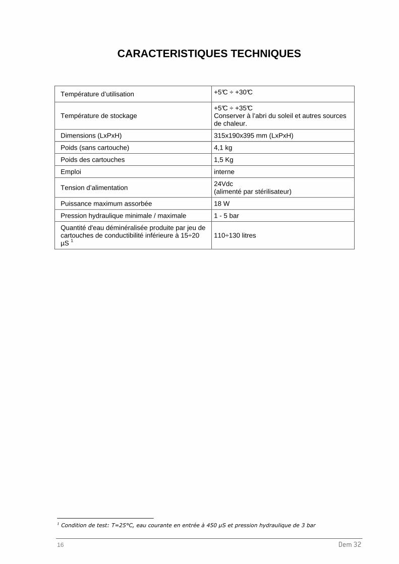
Température d’utilisation +5°C ÷ +30°C
Température de stockage +5°C ÷ +35°C Conserver à l’abri du soleil et autres sources de chaleur.
Dimensions (LxPxH) 315x190x395 mm (LxPxH)
Poids (sans cartouche) 4,1 kg
Poids des cartouches 1,5 Kg
Emploi interne
Tension d’alimentation 24Vdc (alimenté par stérilisateur)
Puissance maximum assorbée 18 W
Pression hydraulique minimale / maximale 1 - 5 bar
Quantité d'eau déminéralisée produite par jeu de cartouches de conductibilité inférieure à 15÷20 µS 1
110÷130 litres
1 Condition de test: T=25°C, eau courante en entrée à 450 µS et pression hydraulique de 3 bar

Dem 32 17
Fra
nçai
s
INSTRUCTIONS DE MAINTENANCE DE LA VANNE DE SECURITE (WATER BLOCK ®)
VANNE DE SECURITE WATER BLOCK (WB) Dispositif indispensable pour machines à laver, lave-vaisselle, déminéralisateurs, etc. car si le débit d'eau est supérieur à celui réglé sur l’indicateur (rupture de tuyau), il bloque le passage de l’eau. Il est doté également d’un clapet anti-retour (anti-pollution). Pour un fonctionnement optimal, le dispositif doit être monté en position verticale, conformément à la fig.2, en suivant soigneusement la notice de montage. CARACTERISTIQUES TECHNIQUES - Pression de rupture: 500 N/cm²
- Pression statique maximal: 100 N/cm²
- Volume maximum contrôlé: 50 l environ.
- Débit minimum de fonctionnement:2 l/min.
- Débit maximum de fonctionnement:30 l/min
- Température maximal de l’eau: 70° C
INSTRUCTIONS Le WATER BLOCK doit être monté entre le robinet d'arrivée d'eau courante et le tuyau d’alimentation du déminéralisateur (fig. 2). Vérifier la position de l'indicateur P qui doit être réglé sur le repère 1,5 . Si nécessaire et à l'aide de la clé fournie, tourner l’indicateur P dans le sens anti-horaire jusqu’à trouver la position exacte. ATTENTION: Pour l’emploi sur des appareils différents, tourner l’indicateur dans la position la plus appropriée en tenant compte du fait que chaque numéro de l’échelle correspond à un volume de 4 à 6 litres. En cas d’installation sur des appareils prévus pour une distribution d’eau potable à l’usage alimentaire, il est conseillé, afin d’éliminer les éventuelles impuretés accumulées durant le stockage, de faire passer au moins 10 litres d’eau du réseau à l’intérieur du dispositif avant le raccordement. MONTAGE 1. Visser manuellement le WB sur le robinet (filetage 3/4” gaz), en
prenant soin d'insérer le filtre E avec la partie bombée orientée vers le haut (fig. 2). Le montage incorrect du filtre empêcherait le bon fonctionnement du WB. En cas de serrage avec un outil, prendre appui sur la partie octogonale A.
2. Visser le tuyau d’alimentation C sur la partie inférieure du WB. Si le tuyau est doté d’un filtre, ce dernier doit être enlevé et remplacé par un joint plat en caoutchouc F. En cas de serrage avec un outil, prendre appui sur la partie hexagonale B pour éviter la rotation du WB pendant l’opération. Si le débit d'eau est supérieur à celui préréglé sur l'indicateur P (fuite), le WB bloque le passage de l’eau. Pour réactiver son fonctionnement, il faut fermer le robinet d'arrivée d’eau, trouver la source du problème, dévisser le tuyau d’alimentation C du WB et appuyer sur le bouton H situé à côté de l’indicateur (fig. 1). En cas de pression élevée, cette opération peut s’avérer difficile. Dans ce cas dévisser légèrement le WB du robinet ce qui facilitera le réarmement du bouton H. Répéter ensuite les opérations indiquées dans le paragraphe “Montage”.
REMARQUE: Pour prévenir d’éventuels dommages causés par le gel de l’eau présente dans le WB après installation, la température ambiante d’utilisation ne doit jamais être inférieure à 2° C. Nous déclinons toute responsabilité liée à une utilisation incorrecte du WB et pour des applications non prévues dans ces instructions. ENTRETIEN: Selon les conditions et la fréquence d’utilisation, nous vous recommandons de nettoyer régulièrement le filtre d’entrée E et de remplacer le joint F. Nous réservons le droit de modifier les caractéristiques sans préavis.
Fig. 1
Produced by ELTEK s.p.a. Tel. 0142 335511 Fax 0142 335555 15033 Casale Monf. (Italy) [email protected]

Dem 32 1
Italia
no
Dem 32
DEMINERALIZZATORE
MANUALE UTENTE
Egregio Dottore, è nostra intenzione, innanzitutto, ringraziarLa per la fiducia che ci ha accordato acquistando il nostro demineralizzatore Dem 32. La informiamo che il produttore rimane a sua completa disposizione per fornire notizie e delucidazioni in merito a tutto quanto concerne questo apparato. Le ricordiamo altresì che, per un corretto uso del demineralizzatore, è strettamente necessario che questo manuale venga letto attentamente prima di utilizzare l’apparato. Infatti, i nostri prodotti rispondono alle norme generali vigenti relative alla sicurezza e non presentano pericolo per l’operatore, se utilizzati secondo le istruzioni prescritte. Nell’augurarLe un proficuo lavoro, Le ricordiamo che è vietata la riproduzione di questo manuale e che, a seguito della continua ricerca e sviluppo tecnologici, le caratteristiche tecniche dell’apparato potrebbero essere modificate senza preavviso.
W&H STERILIZATION S.r.l.

2 Dem 32
INDICE
INTRODUZIONE ......................................................................................................................................3
RACCOMANDAZIONI GENERALI...................................................................................................... 3 RESINE - PRECAUZIONI PER LA SICUREZZA ................................................................................ 4 INDICAZIONI SULLA GARANZIA ....................................................................................................... 5
COMPOSIZIONE DELLA FORNITURA .......................... ........................................................................6
NOTE GENERALI ALLA CONSEGNA ................................................................................................ 6 DIMENSIONI E PESO DELL’IMBALLO .............................................................................................. 6 CONTENUTO DELL’IMBALLO............................................................................................................ 7
INSTALLAZIONE ED UTILIZZO ................................. ............................................................................8
SIGNIFICATO DEI SIMBOLI E DEI DATI RIPORTATI SULLA TARGHETTA.................................... 8 MONTAGGIO DELLE CARTUCCE RESINE ...................................................................................... 9 INSTALLAZIONE............................................................................................................................... 10 SOSTITUZIONE CARTUCCIA RESINE............................................................................................ 12 PRECAUZIONI PER EVITARE IL RISTAGNO DELL’ACQUA.......................................................... 12 FUNZIONAMENTO DEL DEMINERALIZZATORE ........................................................................... 12
MANUTENZIONE...................................................................................................................................14
PULIZIA ESTERNA ........................................................................................................................... 14 MANUTENZIONE DELLA VALVOLA DI SICUREZZA (WATER BLOCK®) ...................................... 14 CONTROLLO PERIODICO DEI DISPOSITIVI DI PROTEZIONE ANTIRIFLUSSO ......................... 14 PARTI DI RICAMBIO......................................................................................................................... 15
CARATTERISTICHE TECNICHE............................... ...........................................................................16
ISTRUZIONI DI MANUTENZIONE VALVOLA DI SICUREZZA (WATER BLOC K®) ...........................17

Dem 32 3
Italia
no
INTRODUZIONE
Il presente manuale ha lo scopo di fornire istruzioni per:
- la corretta installazione; - l’utilizzo sicuro ed efficiente dell'apparato; - la continua e regolare manutenzione.
� Tutte le dimensioni indicate nel manuale non sono vincolanti.
� I disegni e qualsiasi altro documento contenuti in questo manuale sono di proprietà del produttore, che se ne riserva tutti i diritti e non possono essere messi a disposizione di terzi.
� È vietata la riproduzione anche parziale del testo o delle illustrazioni.
RACCOMANDAZIONI GENERALI • L'apparato deve essere usato in ottemperanza alle procedure contenute nel manuale e mai per
scopi diversi da quelli in esso previsti.
• L'utente è responsabile per quanto concerne l'installazione, il corretto utilizzo e la regolare manutenzione dell'apparato secondo le istruzioni riportate in questo manuale.
• Utilizzare solo cartucce specifiche e ricambi originali per questo prodotto.
• Non bere l’acqua prodotta da Dem 32.
• Non otturare o schiacciare i tubi dell’acqua in ingresso e in uscita dall’apparato.
• Qualora l'apparato non fosse fatto funzionare in modo corretto oppure non venga effettuata una adeguata manutenzione, il fabbricante non può essere considerato responsabile di eventuali guasti, rotture, o del cattivo funzionamento dell’apparato stesso.
• Quando in abbinamento con una sterilizzatrice, al superamento del valore di conducibilità di 15-20 µS, sostituire immediatamente le cartucce delle resine. In caso contrario la sterilizzatrice potrebbe danneggiarsi.
• Il demineralizzatore è stato progettato e testato per essere connesso direttamente al rubinetto del
acqua corrente. Connessioni con altri sistemi di trattamento delle acque ad esempio deionizzatori o addolcitore d'acqua potrebbero causare anomalie e/o portare ad una riduzione della durata delle cartucce.
Destinazione d'uso : Il presente manuale costituisce parte integrante del prodotto e deve essere conservato presso l'apparato per una facile e rapida consultazione. Il Dem 32 è da destinarsi solo all'impiego per il quale è stato concepito. Dem 32: Apparato concepito per la demineralizzazione dell’ac qua potabile della
rete idrica, per l’alimentazione manuale e automatica di alcuni sterilizzatori a vapore.

4 Dem 32
RESINE - PRECAUZIONI PER LA SICUREZZA
Pericolo per contatto
Contatto con gli occhi Irritante per gli occhi (R36).
Contatto con la pelle Leggermente irritante per la pelle.
Interventi di primo soccorso
Contatto con la pelle Togliersi di dosso gli strumenti contaminati.
Rimuovere le particelle e lavare la zona interessata con acqua.
Contatto gli occhi Lavare immediatamente e abbondantemente con acqua e rimuovere tutte le particelle.
Provvedimenti in caso di dispersione accidentale
Precauzioni per le persone Tenere lontano le persone.
Rende sdrucciolevole il pavimento: fare attenzione per evitare cadute.
Metodi di bonifica Raccogliere il prodotto e trasferirlo in adeguati imballi di materiale plastico per il suo recupero o smaltimento, secondo quanto indicato.
Note per lo smaltimento
Il prodotto usato è un rifiuto speciale non pericoloso. Il prodotto deve essere smaltito nel rispetto della normativa vigente, sia essa locale, regionale o nazionale. Il numero CER per le resine a scambio ionico sature od esauste usate per la preparazione di acqua potabile od acqua per uso industriale è: 19 09 05.

Dem 32 5
Italia
no
INDICAZIONI SULLA GARANZIA Il produttore garantisce la qualità dei propri apparati se utilizzati in accordo con le istruzioni fornite in questo manuale, per un periodo di 12 mesi per le parti meccaniche, che per quelle elettriche. La garanzia ha inizio dalla data di consegna dell'apparato al cliente, comprovata dalla restituzione del tagliando di garanzia debitamente compilato e firmato. In caso di contestazione, verrà ritenuta valida la data indicata sul Documento di trasporto che riporta il numero di matricola dell'apparato. La garanzia non copre difetti o danni derivanti da:
■ Installazione inadeguata ■ Manutenzione impropria ■ Manomissioni e modifiche non autorizzate ■ Uso scorretto dell'apparato ■ Non rispetto delle indicazioni fornite in questo manuale
È esclusa la sostituzione dell'apparato ed il prolungamento della garanzia a causa dei guasti intervenuti. La riparazione in garanzia viene effettuata ad insindacabile giudizio del produttore e non comprende le spese di imballaggio e trasporto.

6 Dem 32
COMPOSIZIONE DELLA FORNITURA NOTE GENERALI ALLA CONSEGNA Al ricevimento del prodotto controllare che l'imballo sia integro (conservarlo per eventuali spedizioni). Aprire l'imballo e controllare che:
- la fornitura corrisponda al documento di accompagnamento; - non vi siano danni evidenti.
In caso di danni o parti mancanti, informare immediatamente e in modo dettagliato lo spedizioniere, il deposito dentale o il distributore. DIMENSIONI E PESO DELL’IMBALLO Peso lordo: 8,5 Kg Dimensioni in mm

Dem 32 7
Italia
no
CONTENUTO DELL’IMBALLO
Voce Descrizione
1. Apparato demineralizzatore (teste + porta cartucce + O-ring + anelli di centraggio)
2. N. 2 cartucce resine + guarnizione
3. Chiave per sostituzione cartuccia resine
4. Tubo rete idrica con attacco per rubinetto e raccordi per collegamento (4 m, Ø 6x4mm)
5. Valvola sicurezza (Water Block®) con filtro e chiave di regolazione
6. Tubo spiralato con pistola
7. N.1 tubo di carico (2 m, Ø ¼”)
8. Tubo di scarico (3 m, Ø 8x6 mm)
9. N.1 cavo interfaccia con ferrite antidisturbo
10. N.2 Raccordi ad angolo (n.1 per tubo Ø ¼” e n.1 per tubo Ø 8x6 mm)
11. Tasselli e viti per fissaggio a parete
12. Certificato di garanzia, Dichiarazione di Conformità CE e Manuale utente
1
2
3
4 5
7
8
9
10
12
11
6

8 Dem 32
INSTALLAZIONE ED UTILIZZO SIGNIFICATO DEI SIMBOLI E DEI DATI RIPORTATI SULLA TARGHETTA
Nome modello Numero di serie
Pressione operativa
Luogo di fabbricazione
Leggere attentamente il manuale
Codice prodotto Tensione operativa
Potenza assorbita
Anno
SN datamatrix
Marchio CE
Luogo di fabbricazione
Riferimento
direttiva per
smaltimento rifiuti
Apparato dotato di dispositivo di protezione che consente il flusso in una sola direzione, in accordo alla norma EN 1717

Dem 32 9
Italia
no
MONTAGGIO DELLE CARTUCCE RESINE
1. Rimuovere il coperchio delle testate.
2. Rimuovere i tubi dai collegamenti ad innesto rapido ed estrarre la coppia di porta cartucce.
3. Svitare i vasi porta cartucce (se necessario usare l’apposita chiave).
4. Rimuovere il sacchetto protettivo delle cartucce e inserirle nei vasi (parte conica verso il basso e scritta “UP” in alto).
5. Posizionare gli O-Ring sull’imbocco dei vasi porta cartucce e avvitare i vasi (in caso di utilizzo della chiave usare forza moderata).
6. Inserire i vasi nel basamento e centrare correttamente con gli anelli di fissaggio.
7. Ripristinare i tubi sui raccordi IN e OUT della testa (verificare che il raccordo IN sia posizionato a sinistra).
8. Posizionare il coperchio delle testate.
IN
1
2
2
4
OUT
5
2
4
5
7
10 Dem 32
INSTALLAZIONE
a b c
a

Dem 32 11
Italia
no
Utilizzo manuale
Utilizzo automatico con sterilizzatrice
ATTENZIONE Utilizzare solo ricambi originali. La valvola di sicurezza (Water Block®) è dotata di una speciale valvola unidirezionale che impedisce il ritorno di liquidi nella rete idrica ed un possibile conseguente suo inquinamento. A questo scopo la valvola WB deve essere montata in posizione v erticale .
ATTENZIONE Verificare che tutti i tubi siano collegati correttamente. Prima di collegare i tubi verificare che siano tagliati correttamente: taglio a 90° e senza sbavature.
1 2 3
Cavo con ferrite
Tubo scarico acqua
Tubo carico acqua
4 5

12 Dem 32
SOSTITUZIONE CARTUCCIA RESINE Quando utilizzato per una/due sterilizzatrici, sostituire le cartucce al raggiungimento di un valore di conducibilità dell’acqua di 15-20 µS.
1. Chiudere il rubinetto di ingresso acqua.
2. Scaricare la pressione del prodotto utilizzando la pistola in dotazione (controllare che durante questa operazione il rubinetto di collegamento del tubo spiralato sia aperto).
3. Seguire quanto descritto nel precedente paragrafo: MONTAGGIO DELLE CARTUCCE RESINE
4. Riaprire il rubinetto di ingresso acqua. PRECAUZIONI PER EVITARE IL RISTAGNO DELL’ACQUA
ATTENZIONE In conformità alla norma EN 1717, per evitare il degrado della qualità dell’acqua e la crescita di batteri dovuti al ristagno di acqua nelle tubazioni, nel demineralizzatore stesso e nei serbatoi della sterilizzatrice, è necessario svuotare l’intero sistema prima di lasciarlo inutilizzato per lungo tempo.
FUNZIONAMENTO DEL DEMINERALIZZATORE Una volta installato ed allacciato correttamente, il demineralizzatore è in grado di fornire immediatamente l'acqua demineralizzata. Come illustrato nella sezione Installazione, il demineralizzatore può essere utilizzato con una duplice funzione: Utilizzo manuale : l’utilizzo della pistola permette di effettuare il caricamento manuale di serbatoi ed anche lavare strumentazione; Utilizzo automatico : alimentazione automatica di 1 o 2 sterilizzatrici idonee al collegamento con il prodotto (vedere manuale d’uso della sterilizzatrice). Quando nella sterilizzatrice il livello dell’acqua nel serbatoio di carico è inferiore alla soglia minima, la sterilizzatrice alimenta (tensione 24Vdc) attraverso il cavo di interfaccia l’unità esterna che fornisce automaticamente l’acqua di rabbocco. Durante il carico dell’acqua, la sonda di conducibilità a bordo sterilizzatrice monitora il grado di conducibilità dell'acqua. Con l’esaurimento delle resine del filtro o del sistema di trattamento a monte, il valore di conducibilità aumenta e, raggiunta la soglia massima, sul display della sterilizzatrice appare il messaggio di superamento del valore di conducibilità consigliato.
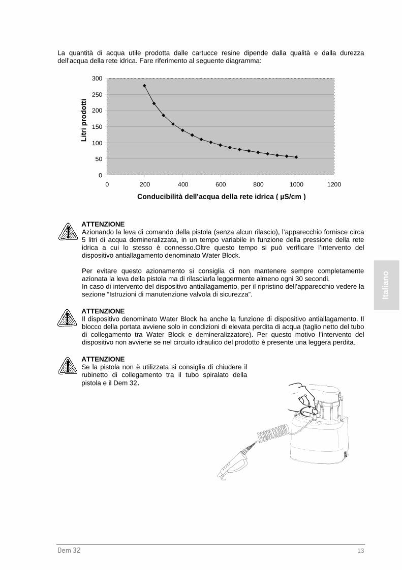
Dem 32 13
Italia
no
La quantità di acqua utile prodotta dalle cartucce resine dipende dalla qualità e dalla durezza dell’acqua della rete idrica. Fare riferimento al seguente diagramma:
0
50
100
150
200
250
300
0 200 400 600 800 1000 1200
Conducibilità dell'acqua della rete idrica ( µS/cm )
Litr
i pro
dott
i
ATTENZIONE Azionando la leva di comando della pistola (senza alcun rilascio), l’apparecchio fornisce circa 5 litri di acqua demineralizzata, in un tempo variabile in funzione della pressione della rete idrica a cui lo stesso è connesso.Oltre questo tempo si può verificare l’intervento del dispositivo antiallagamento denominato Water Block. Per evitare questo azionamento si consiglia di non mantenere sempre completamente azionata la leva della pistola ma di rilasciarla leggermente almeno ogni 30 secondi. In caso di intervento del dispositivo antiallagamento, per il ripristino dell’apparecchio vedere la sezione “Istruzioni di manutenzione valvola di sicurezza”.
ATTENZIONE Il dispositivo denominato Water Block ha anche la funzione di dispositivo antiallagamento. Il blocco della portata avviene solo in condizioni di elevata perdita di acqua (taglio netto del tubo di collegamento tra Water Block e demineralizzatore). Per questo motivo l’intervento del dispositivo non avviene se nel circuito idraulico del prodotto è presente una leggera perdita.
ATTENZIONE Se la pistola non è utilizzata si consiglia di chiudere il rubinetto di collegamento tra il tubo spiralato della pistola e il Dem 32.

14 Dem 32
MANUTENZIONE
PULIZIA ESTERNA Pulire la testa con panno inumidito con detergente non abrasivo e non corrosivo (pH neutro). MANUTENZIONE DELLA VALVOLA DI SICUREZZA (WATER BLOC K®) In funzione della qualità dell’acqua e della frequenza di utilizzo dell’apparato demineralizzatore, si raccomanda di pulire periodicamente il filtro di entrata della valvola secondo quanto definito nel foglio di istruzioni allegato a questo manuale. CONTROLLO PERIODICO DEI DISPOSITIVI DI PROTEZIONE A NTIRIFLUSSO
ATTENZIONE In conformità a quanto richiesto dalla norma EN 1717, far controllare questi dispositivi (Waterblock e valvola di non ritorno) almeno ogni anno eventualmente in concomitanza degli interventi di manutenzione da parte del servizio assistenza della sterilizzatrice. Inoltre si raccomanda di verificare eventuali altri dispositivi presenti sulla sterilizzatrice in modo da garantire che nel punto di connessione idraulica tra demineralizzatore e sterilizzatrice venga sempre garantita almeno la categoria 2 del fluido, secondo le indicazioni della EN 1717.

Dem 32 15
Italia
no
PARTI DI RICAMBIO
Nr. Descrizione Codice
1 COPERTURA TESTATE A812109X
2 COPPIA TESTATA FILTRI A812104X
3 VASO PORTA CARTUCCIA A812103X
4 N. 2 RICAMBI CARTUCCE (N.4 CARTUCCE + ANELLI DI TENUTA + OR) A812100X
5 CHIAVE PER SOSTITUZIONE CARTUCCIA RESINE A812101X
6 PISTOLA A812106X
7 TUBO SPIRALATO A812105X
8 RUBINETTO A812107X
9 TUBO RETE IDRICA CON ATTACCO PER RUBINETTO E RACCORDO (4 M, Ø 6X4MM) A812102X
10 VALVOLA SICUREZZA (WATER BLOCK®) CON FILTRO E CHIAVE DI REGOLAZIONE A812005X
11 VALVOLA DI NON RITORNO A812108X
12 O-R A813014X
13 ANELLO DI CENTRAGGIO A813006X
14 TUBO DI CARICO Ø 1/4” (2 m) W230004X
15 TUBO DI SCARICO Ø 8x6mm (3 m) W230009X
16 ELETTROVALVOLA 24Vdc U382016X
17 CAVO INTERFACCIA (con ferrite antidisturbo) A812004X
18a RACCORDO PER TUBO Ø ¼” W321213X
18b RACCORDO PER TUBO Ø 8X6 mm W321212X
19 OPTIONAL - BRACCIALE PER SCARICO CON ATTACCO A T A812110X
20 OPTIONAL - PROLUNGA TUBO SPIRALATO (2 m) CON ATTACCO A812111X
21 OPTIONAL – KIT DEM 32 SECONDA AUTOCLAVE A812115X
X 4

16 Dem 32
CARATTERISTICHE TECNICHE
Temperatura di esercizio +5°C ÷ +30°C
Temperatura di immagazzinamento +5°C ÷ +35°C tenere al riparo dalla luce diretta del sole e da altre fonti di calore
Dimensioni 315x190x395 mm (LxPxH)
Peso (senza cartuccia) 4,1 kg
Peso cartucce 1,5 Kg
Utilizzo interno
Tensione di alimentazione 24Vdc (fornita dalla sterilizzatrice)
Potenza massima assorbita 18 W
Pressione minima e massima della rete idrica 1 - 5 bar
Quantità di acqua demineralizzata prodotta dalle cartucce con valore di conducibilità non superiore a 15÷20 µS 1
110÷130 litri
1 Condizioni di test: T=25°C, Acqua potabile in entrata a 450 µS e pressione della rete di 3 bar
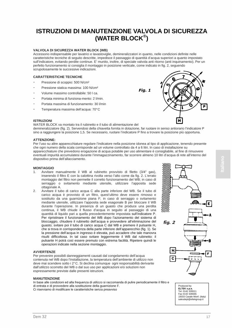
Dem 32 17
Italia
no
ISTRUZIONI DI MANUTENZIONE VALVOLA DI SICUREZZA (WATER BLOCK ®)
VALVOLA DI SICUREZZA WATER BLOCK (WB) Accessorio indispensabile per lavatrici e lavastoviglie, demineralizzatori in quanto, nelle condizioni definite nelle caratteristiche tecniche di seguito descritte, impedisce il passaggio di quantità d’acqua superiori a quanto impostato sull’indicatore, evitando perdite continue. E’ munito, inoltre, di speciale valvola anti ritorno (anti inquinamento). Per un perfetto funzionamento si consiglia il montaggio in posizione verticale, come indicato in fig. 2, seguendo scrupolosamente le successive indicazioni. CARATTERISTICHE TECNICHE
- Pressione di scoppio: 500 N/cm²
- Pressione statica massima: 100 N/cm²
- Volume massimo controllabile: 50 l ca.
- Portata minima di funziona-mento: 2 l/min.
- Portata massima di funzionamento: 30 l/min
- Temperatura massima dell’acqua: 70° C ISTRUZIONI WATER BLOCK va montato tra il rubinetto e il tubo di alimentazione del demineralizzatore (fig. 2). Servendosi della chiavetta fornita in dotazione, far ruotare in senso antiorario l’indicatore P sino a raggiungere la posizione 1,5. Se necessario, ruotare l’indicatore P fino a trovare la posizione più opportuna. ATTENZIONE: Per l’uso su altre apparecchiature regolare l’indicatore nella posizione idonea al tipo di applicazione, tenendo presente che ogni numero della scala corrisponde ad un volume controllato da 4 a 6 litri. In caso di installazione su apparecchiature che prevedono erogazione di acqua potabile per uso alimentare è consigliabile, al fine di rimuovere eventuali impurità accumulatesi durante l’immagazzinamento, far scorrere almeno 10 litri d’acqua di rete all’interno del dispositivo prima dell’allacciamento.
MONTAGGIO 1. Avvitare manualmente il WB al rubinetto provvisto di filetto (3/4” gas),
inserendo il filtro E con la calottina rivolta verso l’alto come da fig. 2. L’errato montaggio del filtro non permette il corretto funzionamento del WB; in caso di serraggio o svitamento mediante utensile, utilizzare l’apposita sede ottagonale A.
2. Avvitare il tubo di carico acqua C alla parte inferiore del WB. Se il tubo di carico acqua è provvisto di un filtro, quest’ultimo deve essere rimosso e sostituito da una guarnizione piana F; in caso di serraggio o svitamento mediante utensile, utilizzare l’apposita sede esagonale B per bloccare il WB durante l’operazione. In presenza di un guasto che produce una perdita continua, il WB chiude il flusso d’acqua in seguito al passaggio di una quantità di liquido pari a quella precedentemente impostata sull’indicatore P. Per ripristinare il funzionamento del WB dopo l’azionamento del sistema di bloccaggio, chiudere il rubinetto dell’acqua e provvedere all’eliminazione del guasto; svitare poi il tubo di carico acqua C dal WB e premere il pulsante H, che si trova in corrispondenza della parte inferiore dell’apparecchio (fig. 1). Se la pressione dell’acqua in ingresso è elevata, può accadere che tale manovra risulti difficoltosa. In tal caso svitare leggermente il WB dal rubinetto: il pulsante H potrà così essere premuto con estrema facilità. Ripetere quindi le operazioni indicate nella sezione montaggio.
AVVERTENZE Per prevenire possibili danneggiamenti causati dal congelamento dell’acqua contenuta nel WB dopo l’installazione, la temperatura dell’ambiente di utilizzo non deve mai scendere sotto i 2° C. Si declina comunque ogni responsabilità derivante dall’utilizzo scorretto del WB o dal suo uso per applicazioni e/o soluzioni non espressamente previste dalle presenti istruzioni. MANUTENZIONE In base alle condizioni ed alla frequenza di utilizzo si raccomanda di pulire periodicamente il filtro e di entrata e di provvedere alla sostituzione della guarnizione F. Ci riserviamo di modificare le caratteristiche senza preavviso
Fig. 1
Produced by ELTEK s.p.a. Tel. 0142 335511 Fax 0142 335555 15033 Casale Monf. (Italy) [email protected]

Dem 32 1
Sve
nska
Dem 32
FÖR FAST VATTENANSLUTNING
BRUKSANVISNING
Bästa kund, Tack för Ert förtroende genom införskaffandet av Dem 32.
Vi ber Er att noggrant läsa igenom denna manual för att försäkra Er om att utrustningen fungerar optimalt. Samtliga våra produkter överensstämmer med gällande säkerhetsnormer och medför inga risker för användaren om de används i enlighet med medskickade instruktioner.
W&H STERILIZATION S.r.l.
Dem 32 2
INDEX
INTRODUKTION......................................................................................................................................3
GENERELLA VARNINGAR................................................................................................................. 3 RESIN – SÄKERHETSÅTGÄRDER.................................................................................................... 4 INFORMATION OM GARANTI............................................................................................................ 5 GENERELLT OM LEVERANSEN ....................................................................................................... 6 PAKETETS MÅTT OCH VIKT ............................................................................................................. 6 INNEHÅLLSFÖRTECKNING............................................................................................................... 7
INSTALLATION OCH ANVÄNDNING........................... ..........................................................................8
SYMBOL-, OCH DATAFÖRKLARING................................................................................................. 8 MONTERING AV FILTRET ................................................................................................................. 9 INSTALLATION ................................................................................................................................. 10 BYTE AV FILTER .............................................................................................................................. 12 FÖRSIKTIGHETSÅTGÄRDER FÖR ATT UNDVIKA STILLASTÅENDE VATTEN........................... 12 ANVÄNDNING................................................................................................................................... 12
UNDERHÅLL .......................................... ...............................................................................................14
EXTERN RENGÖRING ..................................................................................................................... 14 UNDERHÅLL AV SÄKERHETSVENTILEN WATER BLOCK®......................................................... 14 ÅRLIG KONTROLL AV WATER BLOCK® OCH BACKVENTILER .................................................. 14 RESERVDELAR ................................................................................................................................ 15
TEKNISK INFORMATION ................................... ..................................................................................16
MAINTENANCE ISTRUCTIONS FOR THE SAFETY VALVE (WATER BLOCK ®)..............................17

Dem 32 3
Sve
nska
INTRODUKTION
Denna manual ger instruktioner om:
- säker och effektiv drift av utrustningen;
- löpande och schemalagt underhåll.
� Angivna mått i denna manual är ej bindande
� Ritningar och andra dokument levererade med utrustningen tillhör tillverkaren - som reserverar samtliga rättigheter.
� Reproduktion, även i delar, av text och illustrationer är förbjuden. GENERELLA VARNINGAR
• Utrustningen skall användas för de ändamål som beskrivs i denna manual - aldrig för andra
ändamål.
• Användaren är ansvarig för att installation, användandet samt underhåll utförs i enlighet med instruktionerna i denna manual.
• Använd endast originalfilter till denna produkt.
• Drick inte vattnet som produceras av Dem 32.
• Blockera eller kläm inte slangarna till och från autoklaven och Dem 32.
• Om utrustningen inte används korrekt eller underhålls lämpligt, kan inte tillverkaren hållas ansvarig för eventuella fel, skador eller bristande funktionsförmåga hos utrustningen.
• När Dem 32 är ansluten till en autoklav och vattenledningsförmågan överskrider 15-20 µS måste filtren bytas ut omedelbart, annars kan autoklaven skadas.
Användningsområde : Denna manual är en del av utrustningen och skall finnas lätt tillgänglig. Utrustningen skall endast användas för det ändamål den är utvecklad för: Dem 32: Apparat utvecklad för deminiralisering av vatten och manuell eller
automatisk anslutning till autoklaver .

Dem 32 4
RESIN – SÄKERHETSÅTGÄRDER
Kontakt
Ögonkontakt Irriterande (R36).
Hudkontakt Kan irritera.
Första Hjälpen
Ögonkontakt Skölj genast med stora mängder vatten så att resin-resterna sköljs bort.
Hudkontakt Byt ev. kontaminerade kläder.
Ta bort resin-resterna och rengör området med vatten.
Åtgärder vid läckage
Allmänna åtgärder Resin på golvet kan orsaka halt underlag. Varning för halkrisk.
Rengöring Sopa upp resinet. Kastas på samma sätt som tomma filterpatroner.
Avfall
Produkten är inte klassad som farligt avfall.
Ev. lokala eller regionala avfallsbestämmelser skall dock följas.
CER nummret för resinet som används för att producera vattnet är:
19 09 05.

Dem 32 5
Sve
nska
INFORMATION OM GARANTI Tillverkaren ger en garanti på produkten, förutsatt att den underhålls och används i enlighet med manualen, i 12 månader. Garantin gäller från leveransdatumet vilket måste kunna styrkas med inköpsfakturan. Garantin täcker inte defekter eller skador genom:
• Felaktig installation
• Otillräckligt underhåll
• Otillåtna ingrepp i utrustningen
• Felaktigt användande
• Instruktionerna i denna manual inte följs
Ev. utbyte av utrustningen förlänger inte den ursprungliga garantin. Garantinreparationer avgörs och ersätts av tillverkaren och täcker inte kostnader för emballage eller transporter.
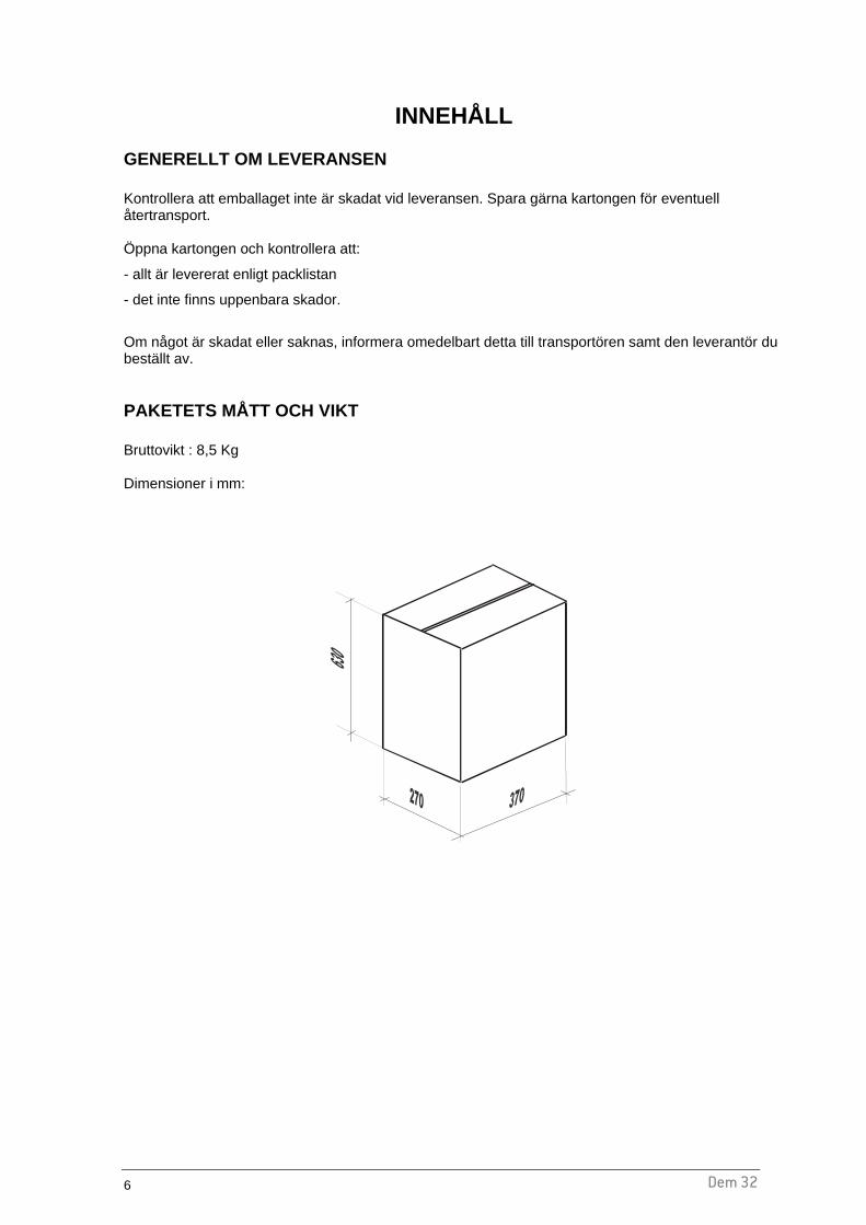
Dem 32 6
INNEHÅLL GENERELLT OM LEVERANSEN Kontrollera att emballaget inte är skadat vid leveransen. Spara gärna kartongen för eventuell återtransport. Öppna kartongen och kontrollera att:
- allt är levererat enligt packlistan
- det inte finns uppenbara skador.
Om något är skadat eller saknas, informera omedelbart detta till transportören samt den leverantör du beställt av. PAKETETS MÅTT OCH VIKT Bruttovikt : 8,5 Kg Dimensioner i mm:
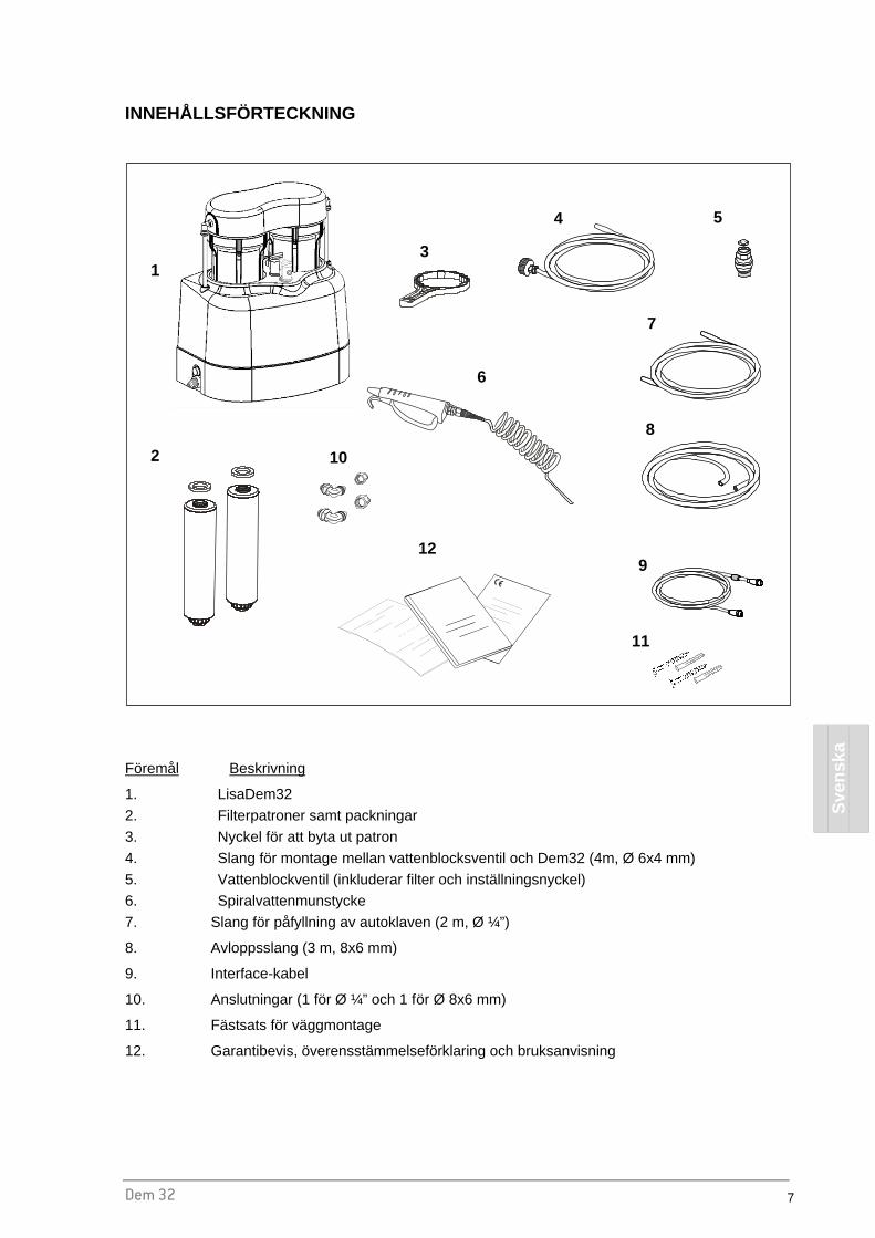
Dem 32 7
Sve
nska
INNEHÅLLSFÖRTECKNING
Föremål Beskrivning
1. LisaDem32
2. Filterpatroner samt packningar 3. Nyckel för att byta ut patron
4. Slang för montage mellan vattenblocksventil och Dem32 (4m, Ø 6x4 mm)
5. Vattenblockventil (inkluderar filter och inställningsnyckel) 6. Spiralvattenmunstycke
7. Slang för påfyllning av autoklaven (2 m, Ø ¼”)
8. Avloppsslang (3 m, 8x6 mm)
9. Interface-kabel
10. Anslutningar (1 för Ø ¼” och 1 för Ø 8x6 mm)
11. Fästsats för väggmontage
12. Garantibevis, överensstämmelseförklaring och bruksanvisning
1
2
3
4 5
7
8
9
10
12
11
6

Dem 32 8
INSTALLATION OCH ANVÄNDNING
SYMBOL-, OCH DATAFÖRKLARING
Modelnamn Seriennummer
Arbetstryck
Tillverkningsland
Läs manualen innan användning
Artikelnummer Spänning
Effektförbrukning
Seriennummer datamatrix
CE märke
Tillverkare
Återvinningssymbol
Utrustningen utrustad med backventil i enlighet med EN 1717
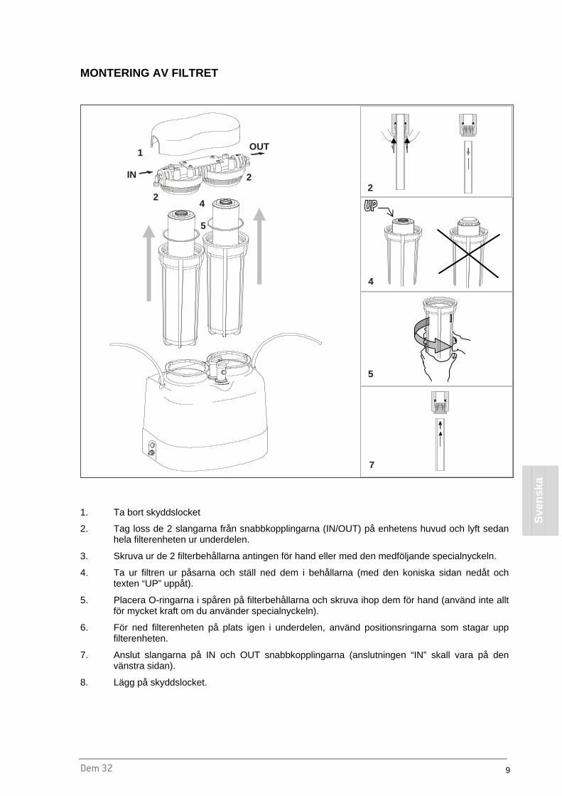
Dem 32 9
Sve
nska
MONTERING AV FILTRET
1. Ta bort skyddslocket
2. Tag loss de 2 slangarna från snabbkopplingarna (IN/OUT) på enhetens huvud och lyft sedan hela filterenheten ur underdelen.
3. Skruva ur de 2 filterbehållarna antingen för hand eller med den medföljande specialnyckeln.
4. Ta ur filtren ur påsarna och ställ ned dem i behållarna (med den koniska sidan nedåt och texten “UP” uppåt).
5. Placera O-ringarna i spåren på filterbehållarna och skruva ihop dem för hand (använd inte allt för mycket kraft om du använder specialnyckeln).
6. För ned filterenheten på plats igen i underdelen, använd positionsringarna som stagar upp filterenheten.
7. Anslut slangarna på IN och OUT snabbkopplingarna (anslutningen “IN” skall vara på den vänstra sidan).
8. Lägg på skyddslocket.
IN
1
2
2
4
OUT
5
2
4
5
7

Dem 32 10
INSTALLATION
b c
a
a
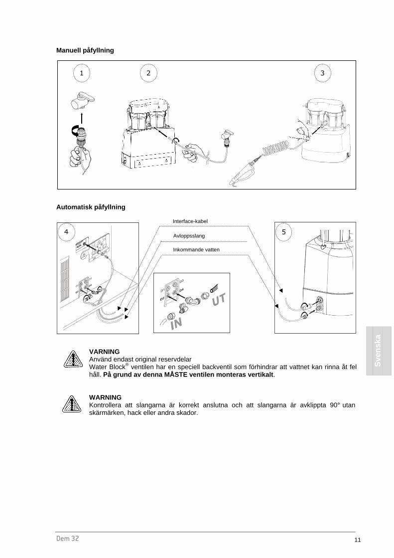
Dem 32 11
Sve
nska
Manuell påfyllning
Automatisk påfyllning
VARNING Använd endast original reservdelar Water Block® ventilen har en speciell backventil som förhindrar att vattnet kan rinna åt fel håll. På grund av denna MÅSTE ventilen monteras vertikalt .
WARNING Kontrollera att slangarna är korrekt anslutna och att slangarna är avklippta 90° utan skärmärken, hack eller andra skador.
1 2 3
Interface-kabel
Avloppsslang
Inkommande vatten
4 5
Dem 32 12
BYTE AV FILTER Filtret skall bytas ut när ledningsförmågan når ett värde på 15-20µS.
1. Stäng av vattnet med kranen på Dem32
2. Släpp ut trycket med hjälp av vattenpistolen
3. Följ stegen i ansnittet “MONTERING AV FILTRET”.
4. Sätt på vattnet med kranen igen.
FÖRSIKTIGHETSÅTGÄRDER FÖR ATT UNDVIKA STILLASTÅENDE VATTEN
OBS! I enlighet med kraven i EN1717 och för att undvika nedsättning av vattenkvaliteten i samband med stillastående vatten, är det nödvändigt att tömma hela systemet innan man låter det stå oanvänt under en längre period.
ANVÄNDNING När Dem32 är korrekt installerad är den klar för att förse vatten till autoklaven. Dem32 kan användas på 2 sätt: Manuellt : Vattenpistolen används för att fylla på autoklaven eller dunkar; Automatisk anslutning : Dem32 kan anslutas till 1 eller 2st Lisor. När Lisas vattentank börjar bli tom, skickas en signal till Dem32 som fyller på tanken. Lisa kontrollerar hela tiden vattenkvaliteten och säger till när vattnets kvalitet inte längre är tillräckligt god.

Dem 32 13
Sve
nska
Mängden rent vatten producerat per filterpatron är direkt beroende på det inkommande vattnets kvalitet. Nedanstående finns en skala på hur mycket vatten som kan renas:
0
50
100
150
200
250
300
0 200 400 600 800 1000 1200
Conductivity of the tap water ( µS/cm )
Litre
s pr
oduc
ed
OBS Dem32 är utrustad med ett Water Block® säkerhetsventil. Denna ventil stänger av vattnet när flödet passerat inställt värde (5 liter) för att förhindra stora vattenläckage. Om Ni använder vattenpistolen för att fylla t.ex. dunkar, släpp ut handtaget var 30:e sekund för att vara säker på att ventilen inte löser ut. Om ventilen löser ut måste den återställas, se avsnittet “Underhåll av säkerhetsventilen WaterBlock”.
VARNING WaterBlock-ventilen fungerar som ett översvämmningsskydd. Ventilen löser ut efter genomflödet av det antal liter vatten som ventilen är inställd för - om trycket är normalt. Ventilen löser inte ut om det är ett mycket litet läckage – Stäng därför alltid av vattnet till systemet när ni går för dagen.
VARNING Låt vattenpistolens vattenkran vara avstängd när inte vattenpistolen används.

Dem 32 14
UNDERHÅLL
EXTERN RENGÖRING Rengör enheten med en fuktad trasa som inte innehåller starka medel (pH neutralt). UNDERHÅLL AV SÄKERHETSVENTILEN WATER BLOCK ®
Rengör ventilens vattenfilter med jämna mellanrum. Hur ofta beror på vattnets och vattenledningarnas kvalitet. Börja med en gång i månaden – om det inte finns något smuts i filtret kan perioden mellan kontrollerna förlängas. ÅRLIG KONTROLL AV WATER BLOCK ® OCH BACKVENTILER
OBS För att överensstämma med kraven i EN1717 (§ 4.6) skall backventilerna (inkl. WaterBlock) kontrolleras en gång per år. Detta görs i samband med den årliga servicen, av en auktoriserad tekniker i enlighet med servicemanualen.
Vi rekommenderar att alla hydraliska anslutningar mellan LisaDem och autoklaven kontrolleras så att de är i överensstämmelse med EN 1717, kategori 2

Dem 32 15
Sve
nska
RESERVDELAR
Nr. Description Code
1 FILTERLOCKSSKYDD A812109X
2 FILTERHUVUD A812104X
3 FILTERPATRONSBEHÅLLARE A812103X
4 FILTERPATRONS KIT (4 PATRONER + 4 PACKNINGAR + 4 O-RINGAR) A812100X
5 NYCKEL FÖR BYTE AV FILTERPATRON A812101X
6 VATTENPISTOL A812106X
7 SPIRALSLANG A812105X
8 KRAN A812107X
9 VATTENSLANG MED KRANANSLUTNING (4 M, Ø 6X4MM) A812102X
10 VATTENSLANG MED KRANANSLUTNING (4 M, Ø 6X4MM) A812005X
11 BACKVENTIL A812108X
12 O-RING A813014X
13 CENTRERINGSRING A813006X
14 SLANG FÖR PÅFYLLNING AV AUTOKLAVEN Ø 1/4” (2 m) W230004X
15 AVLOPPSSLANG Ø 8x6mm (3 m) W230009X
16 ELECTRIC VALVE 24VDC U382016X
17 INTERFACE-KABEL A812004X
18a ANSLUTNING Ø ¼” W321213X
18b ANSLUTNING Ø 8X6 mm W321212X
19 TILLBEHÖR – MONTERINGSKIT FÖR AVLOPPSSLANG A812110X
20 TILLBEHÖR – FÖRLÄNGNINGSSLANG TILL VATTENPISTOLEN A812111X
21 TILLBEHÖR – KIT FÖR EN TILL AUTOKLAV A812115X
X 4

Dem 32 16
TEKNISK INFORMATION
Temperaturområde Drift +5°C ÷ +30°C
Temperaturområde Lagring +5°C ÷ +35°C undvik direkt solljus samt andra värmekällor
Storlek (LxDxH) 315x190x395 mm (LxPxH)
Vikt (utan filterpatroner) 4,1 kg
Filterpatronens vikt (x2) 1,5 Kg
Användningsplats Inomhus
Spänning 24Vdc (drivs av autoklaven)
Maximal effektförbrukning 18W
Min - max vattentryck 1 - 5 bar
Mängden (ca) renat vatten mellan 15-20 uS 110÷130 liter

Dem 32 17
Sve
nska
MAINTENANCE ISTRUCTIONS FOR THE SAFETY VALVE (WATER BLOCK ®)
WATER BLOCK (WB) SAFETY VALVE Indispensable device for washing machines, dishwashers and demineralizers as, under the conditions defined in the technical features herewith described, it prevents a flow of water greater than the one for which it has been set by the adjustment pointer. This avoids continuous leaking. The Water Block also has a particular non-return valve (antipollution). The device should be installed vertically (see fig. 2) and following the instructions carefully. TECHNICAL FEATURES
- Burst pressure: 500 N/cm²
- Max. static pressure: 100 N/cm²
- Max. controllable volume: about 50 lt.
- Min. operating capacity: 2 lt/min.
- Max. operating capacity: 30 lt/min
- Max. water temperature: 70° C
USER INSTRUCTIONS WATER BLOCK should be installed between the tap and the supply hose of the demineralizer (fig. 2). Using the enclosed plastic key, turn pointer ‘P’ (fig. 1) anticlockwise to the required setting (example, position 1,5). CAUTION: For use on other fixtures, set the pointer to a position suitable for that particular application, considering that each number on the scale corresponds to a controlled volume of approx. 4-6 litres. In case of installation on fixtures which foresee dispensing of drinking water for alimentary use it is advisable to let flow at least 10 litres of water inside the device before the connection, so as remove eventual impurities banked during the storage. INSTALLATION 1. Manually screw the WB to the tap having suitable thread (3/4” gas),
inserting the filter ‘E’ with its convex side facing upwards (fig. 2). The WB will not operate properly if the filter is not installed correctly. If the WB is tightened or loosened with the aid of a wrench, the same must be applied to the appropriately octagonally shaped part of the housing ‘A’.
2. Screw the supply hose ‘C’ to the lower end of the WB. If the supply hose is equipped with a filter, the latter must be substituted by a flat rubber washer ‘F’. If the said hose has to be tightened or loosened with the aid of a wrench, the same must be applied to the appropriately octagonally shaped part of the WB housing ‘B’ so as to hold it firmly while performing this operation. If a failure occurs causing a continuous water leak, the WB will shut off when the volume of water flowing through equals the amount to which it was previously set with the pointer ‘P’. To reset the Water Block again after it has shut off, turn the tap off and carry out the necessary repair work. Remove the supply hose ‘C’ from the Water Block and press the coloured plunger ‘H’ which is located inside the lower housing of the device itself (fig. 1). It may be difficult to press this plunger if there is high pressure at the inlet side of the WB. In this case, slacken the device from the tap: the plunger ‘H’ can then be pressed with ease. Repeat the operation as described in the section headed ‘Installation’.
CAUTION: To avoid any possible damage that may be caused by water freezing inside the WB after its installation, the ambient temperature should never be below 2° C. We decline all responsibility deriving from the incorrect use of the WB or from its use for applications and/or solutions not expressly foreseen by the above instructions. MAINTENANCE: Depending on the conditions and frequency of usage of the water block, it is recommended to clean out the inlet filter ‘E’ periodically and to replace the seal ‘F’.We reserve the right to modify any features without prior notice
Fig. 1
Produced by ELTEK s.p.a. Tel. 0142 335511 Fax 0142 335555 15033 Casale Monf. (Italy) [email protected]
Dem 32 1
Suo
mi
Dem 32
DEMINERALISAATTORI
KÄYTTÖOPAS
Hyvä käyttäjä, Haluamme kiittää sinua siitä, että ostit demineralisaattorin Dem 32. Olemme iloisia voidessamme tarjota seuraavat, tuotteen käyttöä koskevat tiedot. Muistutamme, että käyttääksesi demineralisaattoria oikein sinun tulee lukea tämä käyttöohje huolellisesti. Kaikki tuotteemme ovat voimassaolevien turvallisuussäädösten mukaisia eivätkä aiheuta käyttäjälle mitään vaaraa mikäli niitä käytetään ohjeiden kuvailemalla tavalla. Toivottaessamme toimillesi kaikkea menestystä pyydämme sinua myös huomioimaan, että tämän ohjekirjan kopiointi on laitonta, ja että johtuen jatkuvasta tutkimustyöstä ja teknologian kehityksestä laitteen tekniset tiedot saattavat muuttua ilman ennakkoilmoitusta.

2 Dem 32
SISÄLLYSLUETTELO
JOHDANTO ........................................... ..................................................................................................3
YLEISIÄ SUOSITUKSIA ...................................................................................................................... 3 HARTSIPATRUUNAT – VAROTOIMENPITEET................................................................................. 4 TAKUUTIEDOT.................................................................................................................................... 5
PAKKAUKSEN SISÄLTÖ ................................... ....................................................................................6
YLEISIÄ HUOMIOITA TOIMITUKSESTA............................................................................................ 6 PAKKAUKSEN KOKO JA PAINO ....................................................................................................... 6 LÄHETYKSEN SISÄLTÖ..................................................................................................................... 7
ASENNUSJA KÄYTTÖ ..................................... ......................................................................................8
NIMIKILVEN SYMBOLIT ..................................................................................................................... 8 HARTSIPATRUUNOIDEN ASENNUS ................................................................................................ 9 ASENNUS.......................................................................................................................................... 10 HARTSIPATRUUNOIDEN VAIHTO .................................................................................................. 12 VAROTOIMENPITEET VEDEN SAASTUMISEN VÄLTTÄMISEKSI ................................................ 12 DEMINERALISAATTORIN TOIMINTA.............................................................................................. 12
HUOLTO ................................................................................................................................................14
ULKOINEN PUHDISTUS................................................................................................................... 14 WATER BLOCK® -TURVAVENTTIILIN HUOLTO............................................................................. 14 WATER BLOCK® -VENTTIILIN JA YHDENSUUNTAISVENTTIILIEN SÄÄNNÖLLINEN TARKISTUS........................................................................................................................................................... 14 VARAOSALISTA ............................................................................................................................... 15
TEKNISET TIEDOT ...............................................................................................................................16
MAINTENANCE INSTRUCTIONS FOR THE SAFETY VALVE (WATER BLOCK ®) ...........................17

Dem 32 3
Suo
mi
JOHDANTO
Tässä ohjekirjassa käsitellään seuraavia asioita:
- Laitteen turvallinen ja tehokas käyttö - Asianmukainen asennus
- Jatkuva ja aikataulunmukainen huolto.
� Tässä oppaassa mainitut kokoja koskevat tiedot voivat muuttua ilman ennakkoilmoitusta.
� Laitteen mukana toimitetut piirustukset ja muut asiakirjat ovat valmistajan omaisuutta, joka pidättää kaikki oikeudet, eikä niitä saa toimittaa kolmannen osapuolen saataville.
� Tämän ohjekirjan sisältämien tekstien tai kuvien sekä täydellinen että osittainen kopiointi on laitonta.
YLEISIÄ SUOSITUKSIA • Tätä laitetta tulee käyttää ainoastaan tämän ohjekirjan kuvailemalla tavalla eikä sitä tule koskaan
käyttää muihin tarkoituksiin.
• Käyttäjä on vastuussa laitteen tämän ohjekirjan ohjeiden mukaisesta asennuksesta, käytöstä ja huollosta.
• Käytä ainoastaan valmistajan aitoja, tälle tuotteelle tarkoitettuja hartsipatruunoita.
• Älä juo Dem 32:n tuottamaa vettä.
• Älä tuki tai purista sterilisaattorin tai laitteen imu- tai päästöletkuja.
• Valmistaja ei ole vastuussa mistään laitteen vioista, vaurioista tai toimintahäiriöistä, mikäli laitetta ei käytetä tämän ohjekirjan ohjeiden mukaisesti tai sitä ei huolleta kunnolla.
• Käyttäessäsi laitetta yhdessä sterilisaattorin kanssa vaihda hartsipatruunat välittömästi, kun veden johtavuusarvot ylittävät 15-20 µS (useimmat sterilisaattorit antavat varoitusviestin). Näin vältyt sterilisaattorin vahingoittamiselta.
Käyttötarkoitus : Tämä ohjekirja on keskeinen osa tuotetta ja se tulee säilyttää laitteen lähettyvillä siten, että se on nopeasti ja helposti saatavilla. Laitetta tulee käyttää ainoastaan siihen tarkoitukseen, johon se on suunniteltu. Dem 32: Laite juomaveden demineralisointiin sekä manuaalise sti tai
automaattisesti höyrysterilointilaitteeseen tapahtuvaan syöttöön.

4 Dem 32
HARTSIPATRUUNAT – VAROTOIMENPITEET
Kosketusvaarat
Joutuminen silmiin Ärsyttää silmiä (R36).
Joutuminen iholle Ärsyttää ihoa lievästi.
Ensiaputoimenpiteet
Joutuminen iholle Riisu kaikki saastuneet vaatteet.
Poista hartsipisarat ja puhdista alue vedellä.
Joutuminen silmiin Huuhtele silmät välittömästi runsaalla vedellä ja poista hartsipisarat.
Varotoimet vuotojen varalta
Ihmisiä koskevat varotoimet Pidä ihmiset loitolla vuotoalueesta.
Hartsipisarat saattavat tehdä lattiasta liukkaan. Huolehdi siitä, ettet liukastu.
Puhdistusmenetelmät Pyyhi lattia ja siirrä hartsipisarat muoviseen säiliöön takaisinsaantia tai soveltuvien ohjeiden mukaista hävittämistä varten.
Huomioitava hävitettäessä
Käytetty tuote on erityinen, vaaraton jäte. Tuote tulee hävittää voimassa olevia paikallisia, alueellisia tai kansallisia säädöksiä noudattaen. Kyllästetyn tai käytetyn ioninvaihtohartsin, jota käytetään juoma- tai käyttöveden tuottamiseen, CER-päästöyksikkö on: 19 09 05.

Dem 32 5
Suo
mi
TAKUUTIEDOT
Valmistaja myöntää tuotteesi mekaanisille ja elektronisille osille 12 kuukauden takuun, mikäli tuotetta on käytetty tämän ohjekirjan kuvailemalla tavalla. Takuu astuu voimaan päivänä, jolloin tuote on toimitettu asiakkaalle. Toimituspäivä tulee todistaa täyttämällä ja allekirjoittamalla takuutodistus asianmukaisesti. Kiistatilanteessa päiväys, johon laitteen sarjanumero, viittaa on voimassa. Takuu ei korvaa vikoja tai vahinkoja, jotka ovat aiheutuneet:
� Virheellisestä asennuksesta � Riittämättömästä huollosta � Luvattomasta muuntelusta � Laitteen virheellisestä käytöstä � Tämän ohjekirjan ohjeiden huomiotta jättämisestä
Laitteen korvaaminen tai takuuajan pidennys tilanteessa, jossa laitteen rikkoutuminen on poissuljettu. Takuunalainen korjaus suoritetaan valmistajan harkinnan perusteella, eikä siihen sisälly pakkaus- ja lähetyskuluja.

6 Dem 32
PAKKAUKSEN SISÄLTÖ
YLEISIÄ HUOMIOITA TOIMITUKSESTA Kun laite toimitetaan, tarkista pakkauksen kunto ja säilytä se mahdollista tulevaa tarvetta varten. Avaa pakkaus ja varmista että:
- sisältö vastaa lähetysluetteloa - todisteita vahingoista ei ole.
Mikäli vaurioita löytyy tai lähetys on puutteellinen, ilmoita kuljetusliikkeelle ja tavarantoimittajalle välittömästi. PAKKAUKSEN KOKO JA PAINO Kokonaispaino: 8,5 kg Mitat (mm)

Dem 32 7
Suo
mi
LÄHETYKSEN SISÄLTÖ
Nimike Kuvaus
1. Demineralisaattori
2. 2 hartsipatruunaa + 2 tiivistettä
3. Avain patruunoiden vaihtamiseen
4. Vesihanaan asennettava vedensyöttöputki (4 m, Ø 6x4 mm)
5. Turvaventtiili (sisältää suodattimen ja säätimen)
6. Ruiskupistooli spiraaliletkulla
7. Imuletku (2 m, Ø ¼”)
8. Tyhjennysletku (3 m, 8x6 mm)
9. Sarjakaapeli
10. 2 kulmaliitintä (1 putkikoolle Ø ¼” ja 1 koolle Ø 8x6 mm)
11. Ruuveja ja tappeja yksikön kiinnittämiseksi seinään
12. Takuutodistus, EY-vaatimustenmukaisuusvakuutus sekä käyttöopas
1
2
3
4 5
7
8
9
10
12
11
6
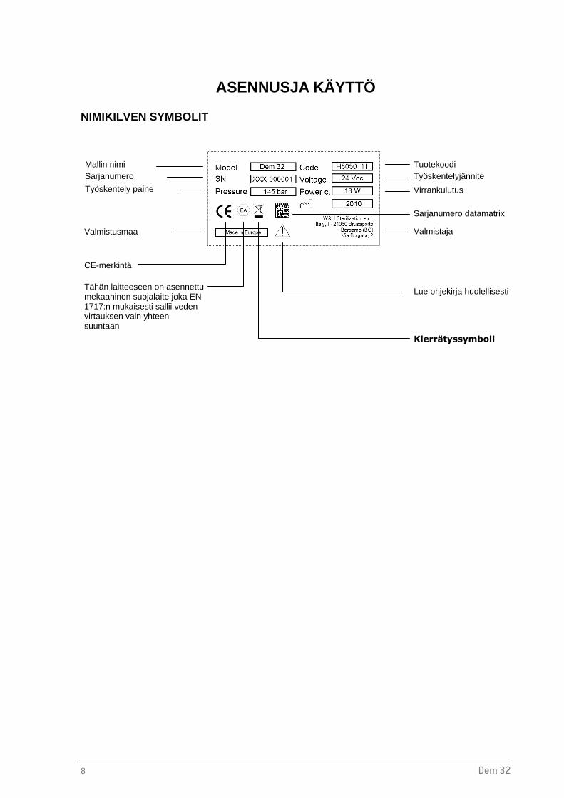
8 Dem 32
ASENNUSJA KÄYTTÖ
NIMIKILVEN SYMBOLIT
Mallin nimi Sarjanumero
Työskentely paine
Valmistusmaa
Lue ohjekirja huolellisesti
Tuotekoodi Työskentelyjännite
Virrankulutus
Sarjanumero datamatrix
CE-merkintä
Valmistaja
Kierrätyssymboli
Tähän laitteeseen on asennettu mekaaninen suojalaite joka EN 1717:n mukaisesti sallii veden virtauksen vain yhteen suuntaan

Dem 32 9
Suo
mi
HARTSIPATRUUNOIDEN ASENNUS
1. Poista suoja suodattimen päästä.
2. Poista putket yksikön pään kahdesta pikaliittimestä (SISÄÄN/ULOS) ja nosta koko patruunakokoonpano ylös demineralisaattorista.
3. Kierrä hartsipatruunan pidikkeet auki (joko käsin tai erityistä avaajaa käyttämällä).
4. Poista suojukset patruunoista ja aseta patruunat pidikkeisiin (kartionmuotoinen puoli alaspäin ja sana “UP” ylöspäin).
5. Aseta o-renkaat hartsipatruunapidikkeiden uraan ja kiristä pidikkeet käsin (käytä voimaa maltillisesti mikäli käytät erityistä avaajaa).
6. Aseta patruunakokoonpano takaisin demineralisaattorin pohjalle ja asenna se paikalleen säätörenkaiden avulla.
7. Aseta putket takaisin SISÄÄN- ja ULOS-liittimiin (varmista, että SISÄÄN-liitin on vasemmalla puolellasi).
8. Kiinnitä suodattimen pään suoja.
SISÄÄN
2
2
4
ULOS
5
2
4
5
SSuomi
7
4

10 Dem 32
ASENNUS
a b c
a

Dem 32 11
Suo
mi
Manuaalinen käyttö
Sterilisaattorin automaattinen täyttö
VAROITUS Käytä ainoastaan alkuperäisiä varaosia Water Block® -venttiili asennetaan yhdessä erityisen yhdensuuntaisventtiilin kanssa, joka estää veden virtauksen takaisin ja siten myös päävesilinjojen mahdollisen saastumisen. Tämän vuoksi turvaventtiili on asennettava pystysuoraan .
VAROITUS Varmista, että kaikki letkut on kiinnitetty asianmukaisesti. Ennen letkujen kiinnittämistä varmista, että ne ovat asianmukaisesti 90 °:n kulmaan leikattuja ja että niissä ei ole leikkaamattomia osia.
1 2 3
4 5
Täyttö
täyttö
Imuletku
12 Dem 32
HARTSIPATRUUNOIDEN VAIHTO Käyttäessäsi hartsipatruunoita sterilisaattorin kanssa vaihda patruunat, kun veden johtavuus saavuttaa arvon 15µ. Useimmat sterilisaattorit antavat varoitusviestin, kun vedenlaatu alittaa tämän rajan.
1. Sulje imuhana
2. Vapauta paine ruiskupistoolin avulla (varmista, että spiraaliletkun liitoshana on auki tämän toimenpiteen aikana).
3. Noudata ohjeita kohdasta “Hartsipatruunoiden asennus”.
4. Avaa imuhana uudelleen.
VAROTOIMENPITEET VEDEN SAASTUMISEN VÄLTTÄMISEKSI
HUOM! EN 1717:n mukaisesti koko järjestelmä on tyhjennettävä ennen pitkäaikaista taukoa sen käytössä. Näin vältytään veden laadun huononemiselta ja bakteerikasvustolta, joka johtuu letkuihin jääneestä vedestä.
DEMINERALISAATTORIN TOIMINTA Demineralisaattori on valmis tuottamaan demineralisoitua vettä välittömästi asianmukaisen asennuksen jälkeen. Kuten kohdassa Asennus näytetään, demineralisaattoria voidaan käyttää kahdella tavalla:
Manuaalinen käyttö : ruiskupistoolia voidaan käyttää manuaalisesti sterilisaattorin vesisäiliön täyttämiseen sekä instrumenttien huuhteluun; Automaattinen käyttö : 1-2 sterilisaattoria, jotka soveltuvat laitteen kanssa käytettäväksi (katso sterilisaattorin käyttöohje), voidaan täyttää automaattisesti. Kun veden määrä sterilisaattorin puhdasvesisäiliössä laskee alle minimirajan, sterilisaattori antaa sarjakaapelin kautta virtaa erilliselle laitteelle ( 24Vdc) käynnistäen näin veden automaattisen syötön sterilisaattoriin. Sterilisaattorin mittari valvoo veden johtavuutta täytön aikana. Kun suodattimen hartsi tai ylävirtauskäsittelyjärjestelmä kuluu liikaa, johtavuusarvot kohoavat ja kun enimmäisraja saavutetaan, varoitusviesti ilmestyy sterilisaattorin näytölle.
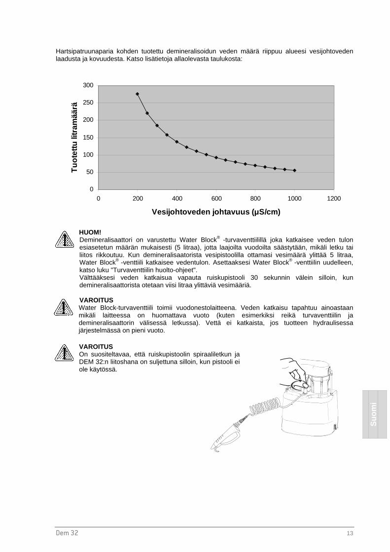
Dem 32 13
Suo
mi
Hartsipatruunaparia kohden tuotettu demineralisoidun veden määrä riippuu alueesi vesijohtoveden laadusta ja kovuudesta. Katso lisätietoja allaolevasta taulukosta:
HUOM! Demineralisaattori on varustettu Water Block® -turvaventtiilillä joka katkaisee veden tulon esiasetetun määrän mukaisesti (5 litraa), jotta laajoilta vuodoilta säästytään, mikäli letku tai liitos rikkoutuu. Kun demineralisaatorista vesipistoolilla ottamasi vesimäärä ylittää 5 litraa, Water Block® -venttiili katkaisee vedentulon. Asettaaksesi Water Block® -venttiilin uudelleen, katso luku "Turvaventtiilin huolto-ohjeet". Välttääksesi veden katkaisua vapauta ruiskupistooli 30 sekunnin välein silloin, kun demineralisaattorista otetaan viisi litraa ylittäviä vesimääriä. VAROITUS Water Block-turvaventtiili toimii vuodonestolaitteena. Veden katkaisu tapahtuu ainoastaan mikäli laitteessa on huomattava vuoto (kuten esimerkiksi reikä turvaventtiilin ja demineralisaattorin välisessä letkussa). Vettä ei katkaista, jos tuotteen hydraulisessa järjestelmässä on pieni vuoto.
VAROITUS On suositeltavaa, että ruiskupistoolin spiraaliletkun ja DEM 32:n liitoshana on suljettuna silloin, kun pistooli ei ole käytössä.
0
50
100
150
200
250
300
0 200 400 600 800 1000 1200
Vesijohtoveden johtavuus ( µS/cm)
Tuo
tettu
litra
mää
rä

14 Dem 32
HUOLTO ULKOINEN PUHDISTUS Puhdista kostealla liinalla ja käytä hankaamatonta ja syövyttämätöntä puhdistusainetta (neutraali pH-arvo). WATER BLOCK ® -TURVAVENTTIILIN HUOLTO Water Block® -venttiilin imusuodatin tulee puhdistaa säännöllisesti, riippuen alueesi veden laadusta ja siitä, kuinka usein demineralisaattori on käytössä.
WATER BLOCK ® -VENTTIILIN JA YHDENSUUNTAISVENTTIILIEN SÄÄNNÖLLINEN TARKISTUS
HUOMIO
Varmistaaksesi että EN 1717 -säädöksiä noudatetaan, tarkastuta Water Block® -venttiili ja yhdensuuntaisventtiilit vähintään kerran vuodessa; jos demineralisaattoriin on yhdistetty sterilisaattori, tarkistus voidaan suorittaa sterilisaattorin aikataulunmukaisen huollon yhteydessä.
Tämän lisäksi on suositeltavaa tarkastaa kaikki sterilisaattoriin liitetyt laitteet, jotta voidaan varmistaa että demineralisaattorin ja sterilisaattorin välinen hydraulinen liitos vastaa EN 1717:n luokkaa 2.

Dem 32 15
Suo
mi
VARAOSALISTA
Nro Kuvaus Koodi
1 SUODATINPÄÄN SUOJUS A812109X
2 SUODATINPÄÄ A812104X
3 PATRUUNANPIDIKE A812103X
4 HARTSIPATRUUNAPAKKAUS (4 PATRUUNAA + 4 TIIVISTERENGASTA + 4 O-RENGASTA) A812100X
5 ERITYISAVAIN PATRUUNANPIDIKKEILLE A812101X
6 RUISKUPISTOOLI A812106X
7 SPIRAALILETKU A812105X
8 HANA A812107X
9 VESIHANAAN ASENNETTAVA SYÖTTÖVESIPUTKI (4 m, Ø 6X4 mm) A812102X
10 TURVAVENTTIILI (WATER BLOCK®), SUODATIN JA SÄÄTÖAVAIN A812005X
11 YHDENSUUNTAISVENTTIILI A812108X
12 O-RENGAS A813014X
13 KESKITYSRENGAS A813006X
14 IMULETKU Ø 1/4” (2 m) W230004X
15 TYHJENNYSLETKU Ø 8x6 mm (3 m) W230009X
16 SÄHKÖVENTTIILI 24 VDC (Volttia, tasavirta) U382016X
17 SARJAKAAPELI A812004X
18a LETKULIITIN Ø ¼” W321213X
18b LETKULIITIN Ø 8X6 mm W321212X
19 VALINNAINEN - TYHJENNYSLETKUN ASENNUSPAKKAUS JA T-KAPPALE A812110X
20 VALINNAINEN - SPIRAALILETKUN JATKO (2 m) JA LIITIN A812111X
21 VALINNAINEN –DEM 32-PAKKAUS TOISELLE PAINEKATTILALLE A812115X
1

16 Dem 32
TEKNISET TIEDOT
Käyttölämpötila +5 °C ÷ +30 °C
Varastointilämpötila +5 °C ÷ +35 °C vältä suoraa auringonpaistetta ja kaikkia lämmönlähteitä
Koko 315x190x395 mm (LxSxK)
Paino (ilman patruunoita) 4,1 kg
Kahden patruunan paino 1,5 kg
Käyttö sisäinen
Työskentelyjännite 24Vdc (virranlähteenä sterilisaattori)
Enimmäisvirrankulutus 18 W
Vesijohtoveden syöttöpaine 1–5 baaria
Yhdellä patruunaparilla tuotetun demineralisoidun veden määrä tilanteessa, jossa veden johtavuusarvo on alle 15÷20 µ 1
110÷130 litraa
1 testattu: Lämpötila=25 °C; vesijohtovedenlaatu 450 µ; vedenpaine 3 baaria

Dem 32 17
Suo
mi
MAINTENANCE INSTRUCTIONS FOR THE SAFETY VALVE (WATER BLOCK ®)
WATER BLOCK (WB) SAFETY VALVE Indispensable device for washing machines, dishwashers and demineralizers as, under the conditions defined in the technical features described below, it prevents a flow of water greater than that for which it has been set by the adjustment pointer. This avoids continuous leaking. The Water Block also has a special non-return valve (antipollution). The device should be installed vertically (see fig. 2) and following the instructions carefully. TECHNICAL FEATURES
- Burst pressure: 500 N/cm²
- Max. static pressure: 100 N/cm²
- Max. controllable volume: about 50 lt.
- Min. operating capacity: 2 lt/min.
- Max. operating capacity: 30 lt/min
- Max. water temperature: 70° C
USER INSTRUCTIONS WATER BLOCK should be installed between the tap and the supply hose of the demineralizer (fig. 2). Using the enclosed plastic key, turn pointer ‘P’ (fig. 1) anticlockwise to the required setting (example, position 1,5). CAUTION: For use on other fixtures, set the pointer to a position suitable for that particular application, considering that each number on the scale corresponds to a controlled volume of approx. 4-6 litres. In case of installation on fixtures which foresee dispensing of drinking water for alimentary use it is advisable to let flow at least 10 litres of water inside the device before the connection, so as remove eventual impurities banked during the storage. INSTALLATION 1. Manually screw the WB to the tap having suitable thread (3/4” gas),
inserting the filter ‘E’ with its convex side facing upwards (fig. 2). The WB will not operate properly if the filter is not installed correctly. If the WB is tightened or loosened with the aid of a wrench, the same must be applied to the appropriately octagonally shaped part of the housing ‘A’.
2. Screw the supply hose ‘C’ to the lower end of the WB. If the supply hose is equipped with a filter, the latter must be substituted by a flat rubber washer ‘F’. If the said hose has to be tightened or loosened with the aid of a wrench, the same must be applied to the appropriately octagonally shaped part of the WB housing ‘B’ so as to hold it firmly while performing this operation. If a failure occurs causing a continuous water leak, the WB will shut off when the volume of water flowing through equals the amount to which it was previously set with the pointer ‘P’. To reset the Water Block again after it has shut off, turn the tap off and carry out the necessary repair work. Remove the supply hose ‘C’ from the Water Block and press the coloured plunger ‘H’ which is located inside the lower housing of the device itself (fig. 1). It may be difficult to press this plunger if there is high pressure at the inlet side of the WB. In this case, slacken the device from the tap: the plunger ‘H’ can then be pressed with ease. Repeat the operation as described in the section headed ‘Installation’.
CAUTION: To avoid any possible damage that may be caused by water freezing inside the WB after its installation, the ambient temperature should never be below 2° C. We decline all responsibility deriving from the incorrect use of the WB or from its use for applications and/or solutions not expressly foreseen by the above instructions. MAINTENANCE: Depending on the conditions and frequency of usage of the water block, it is recommended to clean out the inlet filter ‘E’ periodically and to replace the seal ‘F’.We reserve the right to modify any features without prior notice.
omi
muletku
lish Produced by ELTEK s.p.a. Tel. 0142 335511 Fax 0142 335555 15033 Casale Monf. (Italy) salesdept@eltekgroup

Dem 32 1
Español
Dem 32
DESMINERALIZADOR
MANUAL DEL USUARIO
Estimado Doctor, Queremos, antes de nada, agradecerle la confianza que ha depositado en nosotros adquiriendo nuestro aparato Dem 32. Le informamos que el fabricante permanece a su entera disposición para suministrarle cualquier tipo de información y aclaración en lo que concierne a este aparato. Le recordamos además que, para un uso correcto de Dem 32, es absolutamente necesario que lea este manual atentamente antes de utilizar el aparato. De hecho, nuestros productos cumplen estrictamente las normas generales vigentes relativas a seguridad y no presentan peligro alguno para el operador siempre que sean utilizadas según las instrucciones prescritas. Deseándole un trabajo provechoso, le recordamos que está prohibida la reproducción de este manual y que, debido al continuo estudio y desarrollo tecnológico, las características técnicas del aparato podrían ser modificadas sin previo aviso.
W&H STERILIZATION S.r.l.

2 Dem 32
ÍNDICE
INTRODUCCIÓN......................................................................................................................................3
RECOMENDACIONES GENERALES................................................................................................. 3 RESINAS – PRECAUCIONES DE SEGURIDAD................................................................................ 4 INDICACIONES SOBRE LA GARANTÍA ............................................................................................ 5
COMPOSICIÓN DEL SUMINISTRO........................................................................................................6
NOTAS GENERALES REFERENTE A LA ENTREGA ....................................................................... 6 CONTENIDO DEL EMBALAJE ........................................................................................................... 7
INSTALACIÓN Y USO DEL APARATO......................... .........................................................................8
SIGNIFICADO DE LOS SÍMBOLOS Y DE LOS DATOS INDICADOS EN LA ETIQUETA IDENTIFICATIVA................................................................................................................................. 8 MONTAJE CARTUCHOS DE RESINA ............................................................................................... 9 INSTALACIÓN................................................................................................................................... 10 SUSTITUCIÓN DEL CARTUCHO DE RESINA ................................................................................ 12 PRECAUCIONES PARA EVITAR EL ESTANCAMIENTO DEL AGUA ............................................ 12 FUNCIONAMIENTO .......................................................................................................................... 12
MANTENIMIENTO .................................................................................................................................14
LIMPIEZA EXTERNA ........................................................................................................................ 14 MANTENIMIENTO DE LA VÁLVULA DE SEGURIDAD (WATER BLOCK®).................................... 14 CONTROL PERIÓDICO DE LOS DISPOSITIVOS DE PROTECCIÓN ANTI-REFLUJO................. 14 PIEZAS DE RECAMBIO.................................................................................................................... 15
CARACTERÍSTICAS TÉCNICAS.............................. ............................................................................16
MAINTENANCE INSTRUCTIONS FOR THE SAFETY VALVE (WATER BLOCK ®) ...........................17

Dem 32 3
Español
INTRODUCCIÓN
El objetivo del presente manual es suministrar instrucciones para: - la correcta instalación, - la utilización segura y eficiente del aparato y - el mantenimiento continuo y periódico.
� Las dimensiones indicadas en el manual no son vinculantes.
� Las ilustraciones y cualquier otro documento contenido en este manual es propiedad del fabricante, que tiene reservados todos los derechos y por lo tanto no pueden ponerse a disposición de terceros.
� Está prohibida la reproducción total o parcial del texto y de las ilustraciones. RECOMENDACIONES GENERALES • El aparato debe usarse siguiendo los procedimientos contenidos en el manual y nunca para
finalidades diversas a las previstas en el mismo.
• El usuario es responsable en lo referente a la instalación, el buen uso y mantenimiento regular del aparato según las instrucciones indicadas en este manual.
• Utilizar sólo cartuchos G.F. s.r.l. para este producto.
• No beber el agua producida por Dem 32.
• No bloquear o doblar los tubos de entrada y salida del agua, del aparato y/o del esterilizador.
• El fabricante no se hará responsable de los fallos, daños o mal funcionamiento del equipo con el que no se opere correctamente o no se mantenga de forma adecuada.
• Si, al utilizarlo con un esterilizador, los valores de la conductividad del agua exceden de 15-20 µS, sustituya inmediatamente los cartuchos de resina o el esterilizador podrá resultar dañado.
• El demineralizador ha sido diseñado y testeado para conectarse directamente a la red hídrica
(directo al grifo de agua corriente). Cualquier conexión a cualquier otro sistema de tratamiento de agua, por ejemplo: desionizadores o ablandadores-endulzadores del agua puede causar anomalías y/o reducción del tiempo de vida de los cartuchos.
Uso apropiado del aparato: El presente manual forma parte integrante del producto y debe ser conservado junto al aparato para una consulta fácil y rápida. El aparato está destinado sólo al trabajo para el cual ha sido diseñado. Dem 32: Aparato diseñado para la desmineralización de agua cor riente y suministro,
manual o automatizado, para esterilizadores de vapor.

4 Dem 32
RESINAS – PRECAUCIONES DE SEGURIDAD
Peligro por contacto
Contacto con los ojos Irritante para los ojos (R36).
Contacto con la piel Ligeramente irritante para la piel.
Intervenciones de primeros auxilios
Contacto con la piel Quitarse las ropas contaminadas.
Eliminar las partículas y lavar la zona afectada con agua.
Contacto con los ojos Lavar inmediatamente con abundante agua y eliminar todas las partículas.
Medidas en caso de dispersión accidental
Precauciones para las personas Mantener alejadas a las personas. Hace resbaladizo el suelo: prestar atención para evitar caídas.
Métodos de recogida Recoger el producto y trasladarlo en embalajes adecuados de material plástico para su recuperación o eliminación, según se indica mas adelante.
Notas para la eliminación
El producto usado es un desecho especial no peligroso. El producto debe ser eliminado respetando la normativa vigente, siendo la misma local, regional o nacional.
El número CER para las resinas de intercambio iónico saturadas o exhaustas usadas para la preparación de agua potable o agua para uso industrial es: 19 09 05.

Dem 32 5
Español
INDICACIONES SOBRE LA GARANTÍA El fabricante garantiza la calidad de sus aparatos siempre que sean utilizados de acuerdo a las instrucciones suministradas en este manual, durante un periodo de 12 meses tanto para las partes mecánicas como para las eléctricas. La garantía comienza a partir de la entrega del aparato al cliente, comprobada por la restitución de la tarjeta de garantía debidamente rellenada y firmada. En caso de duda, se considerará válida la fecha indicada en el documento de transporte que indica el número de serie del aparato. La garantía no cubre defectos o daños que deriven de:
� Instalación inadecuada � Mantenimiento inapropiado � Mantenimiento y modificaciones no autorizadas � Uso incorrecto del aparato � El no respetar las indicaciones suministradas en este manual Se excluye la sustitución del aparato y la prolongación de la garantía por causa de averías reparadas por servicios técnicos no autorizados.
La reparación en garantía se efectúa a juicio incuestionable del fabricante y no comprende los gastos de embalaje y transporte.

6 Dem 32
COMPOSICIÓN DEL SUMINISTRO
NOTAS GENERALES REFERENTE A LA ENTREGA Al recibir el producto controle que el embalaje esté íntegro (conservarlo para eventuales envíos). Abrir el embalaje y controlar que:
- el suministro corresponde al documento de presentación, y - que no haya daños evidentes.
En caso de daños o partes no recibidas, informar inmediatamente y de manera detallada al consignatario o al depósito dental. DIMENSIONES Y PESO DEL EMBALAJE Peso bruto: 8,5 Kg. Dimensiones en mm

Dem 32 7
Español
CONTENIDO DEL EMBALAJE
Elemento Descripción
1. Desmineralizador
2. 2 cartuchos de resina + anillo de sellado 3. Llave para sustituir los cartuchos
4. Tubo de alimentación de agua con conexión de agua corriente (4m, Ø 6x4 mm)
5. Válvula de bloqueo de agua (incluye filtro y llave reguladora)
6. Pistola de agua y tubo espiral
7. Tubo de entrada (2 m, Ø ¼”)
8. Tubo de salida (3 m, 8x6 mm)
9. Cable Interface
10. 2 Conectores en Ángulo (1 para el tubo Ø ¼” y 1 para el tubo Ø 8x6 mm)
11. Tornillos y tacos para fijar la unidad a la pared
12. Certificado de garantía, Declaración de conformidad CE y manual del usuario
1
2
3
4 5
7
8
9
10
12
11
6

8 Dem 32
INSTALACIÓN Y USO DEL APARATO
SIGNIFICADO DE LOS SÍMBOLOS Y DE LOS DATOS INDICADO S EN LA ETIQUETA IDENTIFICATIVA
Nombre del producto Número de serie
Presión de funcionamiento
Lugar de fabricación
Leer el manual
Código del producto Voltaje de Trabajo
Potencia de consumo
Número de serie datamatrix
Marca CE
Fabricante
Símbolo de reciclaje
Aparato dotado de dispositivo mecánico de protección que consiente en un flujo en una sola dirección; Conforme a la normativa EN1717

Dem 32 9
Español
MONTAJE CARTUCHOS DE RESINA
1. Extraer la cubierta del cabezal del filtro.
2. Extraer los tubos de los dos conectores rápidos (IN/OUT) situados en el cabezal de la unidad y levantar los porta cartuchos encajados en la base del desmineralizador.
3. Desenroscar los dos porta cartuchos (a mano o usando una llave especial).
4. Extraiga de la bolsa los cartuchos y colóquelos en su porta cartuchos (con la parte cónica hacia abajo y la palabra “UP” hacia arriba).
5. Coloque las juntas tóricas en su alojamiento en el porta cartuchos y enrosque éstos a mano (si utiliza la llave especial apriete con moderada fuerza).
6. Vuelva a colocar todo el conjunto en la base del desmineralizador y fíjela en su lugar mediante el uso de los anillos de posicionamiento.
7. Vuelva a conectar los tubos en los conectores de entrada IN y salida OUT (asegúrese que el conector de entrada IN esta colocado en la parte izquierda).
8. Acople la cubierta del cabezal del filtro.
IN
1
2
2
4
OUT
5
2
4
5
7

10 Dem 32
INSTALACIÓN
b c
a
a
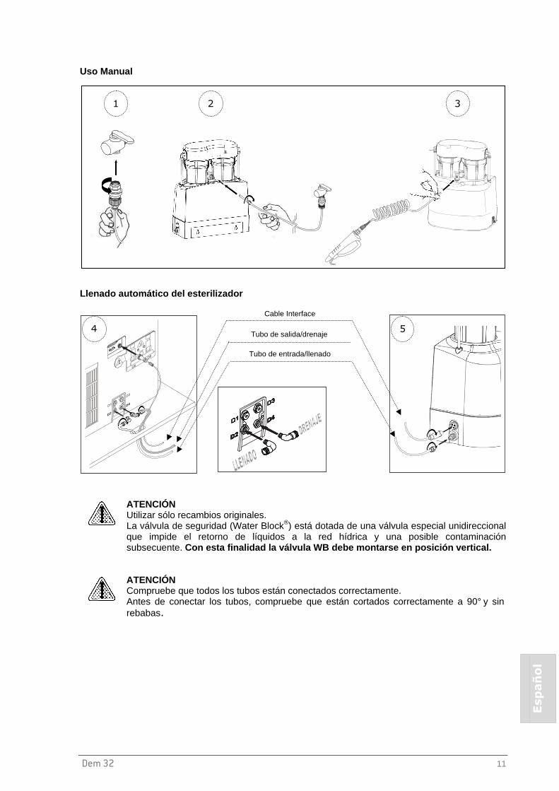
Dem 32 11
Español
Uso Manual
Llenado automático del esterilizador
ATENCIÓN Utilizar sólo recambios originales. La válvula de seguridad (Water Block®) está dotada de una válvula especial unidireccional que impide el retorno de líquidos a la red hídrica y una posible contaminación subsecuente. Con esta finalidad la válvula WB debe montarse en posición ver tical.
ATENCIÓN Compruebe que todos los tubos están conectados correctamente. Antes de conectar los tubos, compruebe que están cortados correctamente a 90° y sin rebabas.
1 2 3
Cable Interface
Tubo de salida/drenaje
Tubo de entrada/llenado
4 5
12 Dem 32
SUSTITUCIÓN DEL CARTUCHO DE RESINA Si se utiliza con un esterilizador, sustituya el cartucho de resina cuando la conductividad alcance el valor de 15-20 µS para rellenar el agua del esterilizador.
1. Cierre la toma del suministro de agua.
2. Libere la presión interna utilizando la pistola de agua suministrada (asegúrese que el grifo que conecta el tubo espiral está abierto durante esta operación).
3. Siga las instrucciones descritas en el capítulo anterior Montaje del cartucho de resina.
4. Abra el grifo de entrada de agua.
PRECAUCIONES PARA EVITAR EL ESTANCAMIENTO DEL AGUA
ATENCIÓN En conformidad con la norma EN1717, para evitar el deterioro de la calidad del agua y el aumento de bacterias debidas al estancamiento del agua en las tuberías, en el mismo aparato y en los depósitos del esterilizador, es necesario vaciar el sistema entero antes de dejarlo inactivo durante un largo período de tiempo (más de 10 días).
FUNCIONAMIENTO Una vez instalado y conectado correctamente, el aparato es capaz de suministrar inmediatamente el agua desmineralizada. Este agua está lista para cargarse manualmente en el tanque de agua del esterilizador (ver el manual del usuario del esterilizador). Tal y como se muestra en la sección Instalación, el desmineralizador puede ser utilizado de dos modos:
Uso Manual : La pistola de agua puede usarse para rellenar manualmente el tanque de agua del esterilizador y también para aclarar los instrumentos; Uso Automático : Puede suministrarse agua de forma automática a 1 o 2 esterilizadores que sean adecuados para usarse con Dem 32 (ver el manual del usuario del esterilizador). Cuando la cantidad de agua, en el tanque de agua limpia del esterilizador, es inferior a los niveles mínimos, el esterilizador alimenta el aparato externo (a 24Vdc) a través del cable interface y automáticamente se suministra agua al esterilizador. Durante el llenado de agua, el medidor de conductividad interno del esterilizador monitoriza la conductividad del agua. Cuando los filtros de resina, u otro sistema de tratamiento, estén agotados, el valor de la conductividad aumenta y una vez se alcanza el nivel máximo un mensaje de advertencia aparece en la pantalla táctil del esterilizador.

Dem 32 13
Español
La cantidad de agua útil producida por un cartucho de resina depende de la calidad y de la dureza del agua de la red hídrica, según la gráfica siguiente:
ATENCIÓN El dispositivo garantiza unos 5 litros de agua desmineralizada al mantener presionada la palanca de la pistola. La duración puede variar dependiendo de la presión hídrica. Al llegar a los cinco litros, se produce un bloqueo y se cierra el suministro de agua. Para evitar este tipo de acciones, se recomienda dejar de presionar la palanca de la pistola de agua cada 30 segundos. En el caso de que se active el bloqueo de agua, consulte la sección “Mantenimiento de la válvula de seguridad”.
ATENCIÓN El Water Block sirve como dispositivo anti-inundación. El sistema de bloqueo solo funciona si hay una fuga considerable (como una rotura en el tubo entre el Water Block y el desmineralizador). El sistema de bloqueo no funciona si hay una pequeña pérdida en el circuito hídrica.
ATENCIÓN Se recomienda que el grifo de conexión, entre el tubo espiral de la pistola y Dem 32, permanezca cerrado si no se está usando.
0
50
100
150
200
250
300
0 200 400 600 800 1000 1200
Conductividad del agua corriente ( µS/cm )
Litr
os p
rodu
cido
s

14 Dem 32
MANTENIMIENTO
LIMPIEZA EXTERNA Limpiar el cabezal con un trapo humedecido con un detergente no abrasivo y no corrosivo (pH neutro). MANTENIMIENTO DE LA VÁLVULA DE SEGURIDAD (WATER BLO CK®) En función de la calidad del agua y de la frecuencia de uso del aparato, se recomienda limpiar periódicamente el filtro de entrada de la válvula según el procedimiento indicado al final de este manual. CONTROL PERIÓDICO DE LOS DISPOSITIVOS DE PROTECCIÓN ANTI-REFLUJO
ATENCIÓN Para mantener la conformidad con la norma EN1717, de deben controlar los dispositivos anti-reflujo (Waterblock y válvula antiretorno) al menos todos los años y/o coincidiendo con las intervenciones de mantenimiento por parte del servicio de asistencia.
Se recomienda verificar todos los aparatos conectados al esterilizador para asegurar que la conexión entre el desmineralizador y el esterilizador corresponde a la categoría 2, de acuerdo a la norma EN 1717.

Dem 32 15
Español
PIEZAS DE RECAMBIO
Nº Descripción NP 1 CUBIERTA DEL FILTRO A812109X
2 CABEZAL DEL FILTRO A812104X
3 RECIPIENTE PORTACARTUCHOS A812103X
4 KIT CARTUCHOS DE RESINA (4 CARTUCHOS DE RESINA + 4 JUNTA TÓRICA + 4 O-R) A812100X
5 LLAVE PARA LA SUSTITUCIÓN DE CARTUCHOS DE RESINA A812101X
6 PISTOLA DE AGUA A812106X
7 TUBO ESPIRAL A812105X
8 TOMA A812107X
9 TUBO ENTRADA AGUA CON CONEXIÓN PARA GRIFO Y RACOR (4 M, Ø 6X4MM) A812102X
10 VÁLVULA DE SEGURIDAD (WATER BLOCK®) CON FILTRO Y LLAVE REGULADORA A812005X
11 VÁLVULA UNIDIRECCIONAL A812108X
12 O-RING A813014X
13 ANILLO DE POSICIONAMIENTO A813006X
14 TUBO DE ENTRADA Ø 1/4” (2 m) W230004X
15 TUBO DE DRENAJE Ø 8x6mm (3 m) W230009X
16 ELECTROVÁLVULA 24VDC U382016X
17 CABLE INTERFACE A812004X
18a CONECTOR EN ÁNGULO PARA TUBO Ø ¼” W321213X
18b CONECTOR EN ÁNGULO PARA TUBO Ø 8X6 mm W321212X
19 OPCIONAL – KIT TUBO DE DRENAJE CON CONECTOR T A812110X
20 OPCIONAL - EXTENSION TUBO ESPIRAL (2 m) CON CONECTOR A812111X
21 OPCIONAL –DEM 32 KIT PARA UNA SEGUNDA AUTOCLAVE A812115X
X 4

16 Dem 32
CARACTERÍSTICAS TÉCNICAS
Temperatura de uso +5°C ÷ +30°C
Temperatura de almacenamiento +5°C ÷ +35°C (no exponer a la humedad o fuentes de calor)
Dimensiones (LxPxH) 315x190x395 mm (LxPxH)
Peso (sin cartuchos) 4.1 Kg.
Peso de 2 cartuchos 1.5 Kg.
Uso Interno
Tension de Alimentación 24Vdc (alimentado mediante el esterilizador)
Máx. potencia absorbida 18 W
Rango de presión en el grifo de entrada 1 - 5 bar
Agua desmineralizada producida por los cartuchos con un valor de conductividad no superior a los 15÷20 µS 1
110÷130 litros
1 probada a: T=25 °C, agua corriente de entrada a 450 µS y presión hídrica de 3 bar
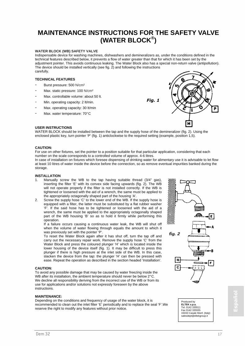
Dem 32 17
Español
MAINTENANCE INSTRUCTIONS FOR THE SAFETY VALVE (WATER BLOCK ®)
WATER BLOCK (WB) SAFETY VALVE Indispensable device for washing machines, dishwashers and demineralizers as, under the conditions defined in the technical features described below, it prevents a flow of water greater than that for which it has been set by the adjustment pointer. This avoids continuous leaking. The Water Block also has a special non-return valve (antipollution). The device should be installed vertically (see fig. 2) and following the instructions carefully. TECHNICAL FEATURES
- Burst pressure: 500 N/cm²
- Max. static pressure: 100 N/cm²
- Max. controllable volume: about 50 lt.
- Min. operating capacity: 2 lt/min.
- Max. operating capacity: 30 lt/min
- Max. water temperature: 70° C
USER INSTRUCTIONS WATER BLOCK should be installed between the tap and the supply hose of the demineralizer (fig. 2). Using the enclosed plastic key, turn pointer ‘P’ (fig. 1) anticlockwise to the required setting (example, position 1,5). CAUTION: For use on other fixtures, set the pointer to a position suitable for that particular application, considering that each number on the scale corresponds to a controlled volume of approx. 4-6 litres. In case of installation on fixtures which foresee dispensing of drinking water for alimentary use it is advisable to let flow at least 10 litres of water inside the device before the connection, so as remove eventual impurities banked during the storage. INSTALLATION 1. Manually screw the WB to the tap having suitable thread (3/4” gas),
inserting the filter ‘E’ with its convex side facing upwards (fig. 2). The WB will not operate properly if the filter is not installed correctly. If the WB is tightened or loosened with the aid of a wrench, the same must be applied to the appropriately octagonally shaped part of the housing ‘A’.
2. Screw the supply hose ‘C’ to the lower end of the WB. If the supply hose is equipped with a filter, the latter must be substituted by a flat rubber washer ‘F’. If the said hose has to be tightened or loosened with the aid of a wrench, the same must be applied to the appropriately octagonally shaped part of the WB housing ‘B’ so as to hold it firmly while performing this operation. If a failure occurs causing a continuous water leak, the WB will shut off when the volume of water flowing through equals the amount to which it was previously set with the pointer ‘P’. To reset the Water Block again after it has shut off, turn the tap off and carry out the necessary repair work. Remove the supply hose ‘C’ from the Water Block and press the coloured plunger ‘H’ which is located inside the lower housing of the device itself (fig. 1). It may be difficult to press this plunger if there is high pressure at the inlet side of the WB. In this case, slacken the device from the tap: the plunger ‘H’ can then be pressed with ease. Repeat the operation as described in the section headed ‘Installation’.
CAUTION: To avoid any possible damage that may be caused by water freezing inside the WB after its installation, the ambient temperature should never be below 2° C. We decline all responsibility deriving from the incorrect use of the WB or from its use for applications and/or solutions not expressly foreseen by the above instructions. MAINTENANCE: Depending on the conditions and frequency of usage of the water block, it is recommended to clean out the inlet filter ‘E’ periodically and to replace the seal ‘F’.We reserve the right to modify any features without prior notice.
Fig. 1
Produced by ELTEK s.p.a. Tel. 0142 335511 Fax 0142 335555 15033 Casale Monf. (Italy) [email protected]

Importer: Manufacturer: W&H Sterilization S.r.l Italy, I-24060 Brusaporto (BG) Via Bolgara, 2 t +39/035/66 63 000 f +39/035/50 96 988 e [email protected] wh.com