user manual - az849230.vo.msecnd.net · user manual control and manage ... en caso de existir, ......
TRANSCRIPT

User Manual
Control and Manage Critical Systems using the ControlBridge Wired Touch Panel Desk along with the ControlBridge Processor.
ControlBridge Wired Touch Panel Desk
CB-TOUCH7-T CB-TOUCH12-T
Order toll-free in the U.S. or for FREE technical support: Call 877-877-BBOX (outside U.S. call 724-746-5500)www.blackbox.com • [email protected]
Contact
Information

877-877-2269 | blackbox.com Page 2
Trademarks Used in this Manual
We‘re here to help! If you have any questions about your application or our products, contact Black Box Tech Support at 877-877-2269
or go to blackbox.com and click on “Talk to Black Box.”You’ll be live with one of our technical experts in less than 60 seconds.
Trademarks Used in this Manual
Black Box and the Double Diamond logo are registered trademarks of BB Technologies, Inc.
Windows is a registered trademark of Microsoft Corporation in the United States and/or other countrie
Any other trademarks mentioned in this manual are acknowledged to be the property of the trademark owners.

Page 3877-877-2269 | blackbox.com
FCC and IC RFI Statements
Federal Communications Commission and Industry Canada Radio Frequency Interference Statements
This equipment generates, uses, and can radiate radio-frequency energy, and if not installed and used properly, that is, in strict accordance with the manufacturer’s instructions, may cause inter ference to radio communication. It has been tested and found to comply with the limits for a Class A computing device in accordance with the specifications in Subpart B of Part 15 of FCC rules, which are designed to provide reasonable protection against such interference when the equipment is operated in a commercial environment. Operation of this equipment in a residential area is likely to cause interference, in which case the user at his own expense will be required to take whatever measures may be necessary to correct the interference.
Changes or modifications not expressly approved by the party responsible for compliance could void the user’s authority to operate the equipment.
This digital apparatus does not exceed the Class A limits for radio noise emis sion from digital apparatus set out in the Radio Interference Regulation of Industry Canada.
Le présent appareil numérique n’émet pas de bruits radioélectriques dépassant les limites applicables aux appareils numériques de la classe A prescrites dans le Règlement sur le brouillage radioélectrique publié par Industrie Canada.
Disclaimer:Black Box Network Services shall not be liable for damages of any kind, including, but not limited to, punitive, consequential or cost of cover damages, resulting from any errors in the product information or specifications set forth in this document and Black Box Network Services may revise this document at any time without notice.
877-877-2269 | blackbox.com Page 4
NOM Statement
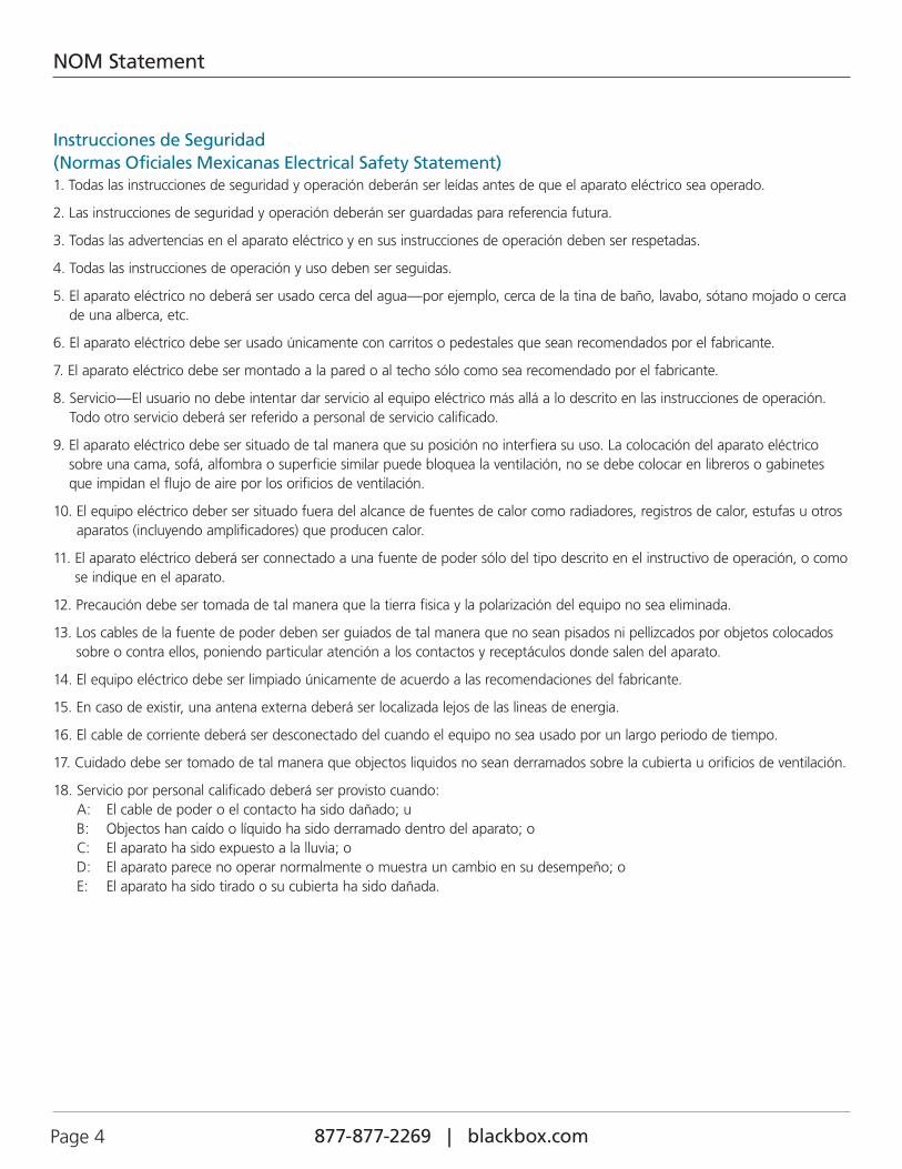
Instrucciones de Seguridad(Normas Oficiales Mexicanas Electrical Safety Statement)1. Todas las instrucciones de seguridad y operación deberán ser leídas antes de que el aparato eléctrico sea operado.
2. Las instrucciones de seguridad y operación deberán ser guardadas para referencia futura.
3. Todas las advertencias en el aparato eléctrico y en sus instrucciones de operación deben ser respetadas.
4. Todas las instrucciones de operación y uso deben ser seguidas.
5. El aparato eléctrico no deberá ser usado cerca del agua—por ejemplo, cerca de la tina de baño, lavabo, sótano mojado o cerca de una alberca, etc.
6. El aparato eléctrico debe ser usado únicamente con carritos o pedestales que sean recomendados por el fabricante.
7. El aparato eléctrico debe ser montado a la pared o al techo sólo como sea recomendado por el fabricante.
8. Servicio—El usuario no debe intentar dar servicio al equipo eléctrico más allá a lo descrito en las instrucciones de operación. Todo otro servicio deberá ser referido a personal de servicio calificado.
9. El aparato eléctrico debe ser situado de tal manera que su posición no interfiera su uso. La colocación del aparato eléctrico sobre una cama, sofá, alfombra o superficie similar puede bloquea la ventilación, no se debe colocar en libreros o gabinetes que impidan el flujo de aire por los orificios de ventilación.
10. El equipo eléctrico deber ser situado fuera del alcance de fuentes de calor como radiadores, registros de calor, estufas u otros aparatos (incluyendo amplificadores) que producen calor.
11. El aparato eléctrico deberá ser connectado a una fuente de poder sólo del tipo descrito en el instructivo de operación, o como se indique en el aparato.
12. Precaución debe ser tomada de tal manera que la tierra fisica y la polarización del equipo no sea eliminada.
13. Los cables de la fuente de poder deben ser guiados de tal manera que no sean pisados ni pellizcados por objetos colocados sobre o contra ellos, poniendo particular atención a los contactos y receptáculos donde salen del aparato.
14. El equipo eléctrico debe ser limpiado únicamente de acuerdo a las recomendaciones del fabricante.
15. En caso de existir, una antena externa deberá ser localizada lejos de las lineas de energia.
16. El cable de corriente deberá ser desconectado del cuando el equipo no sea usado por un largo periodo de tiempo.
17. Cuidado debe ser tomado de tal manera que objectos liquidos no sean derramados sobre la cubierta u orificios de ventilación.
18. Servicio por personal calificado deberá ser provisto cuando: A: El cable de poder o el contacto ha sido dañado; u B: Objectos han caído o líquido ha sido derramado dentro del aparato; o C: El aparato ha sido expuesto a la lluvia; o D: El aparato parece no operar normalmente o muestra un cambio en su desempeño; o E: El aparato ha sido tirado o su cubierta ha sido dañada.
Page 5877-877-2269 | blackbox.com
Table of Contents
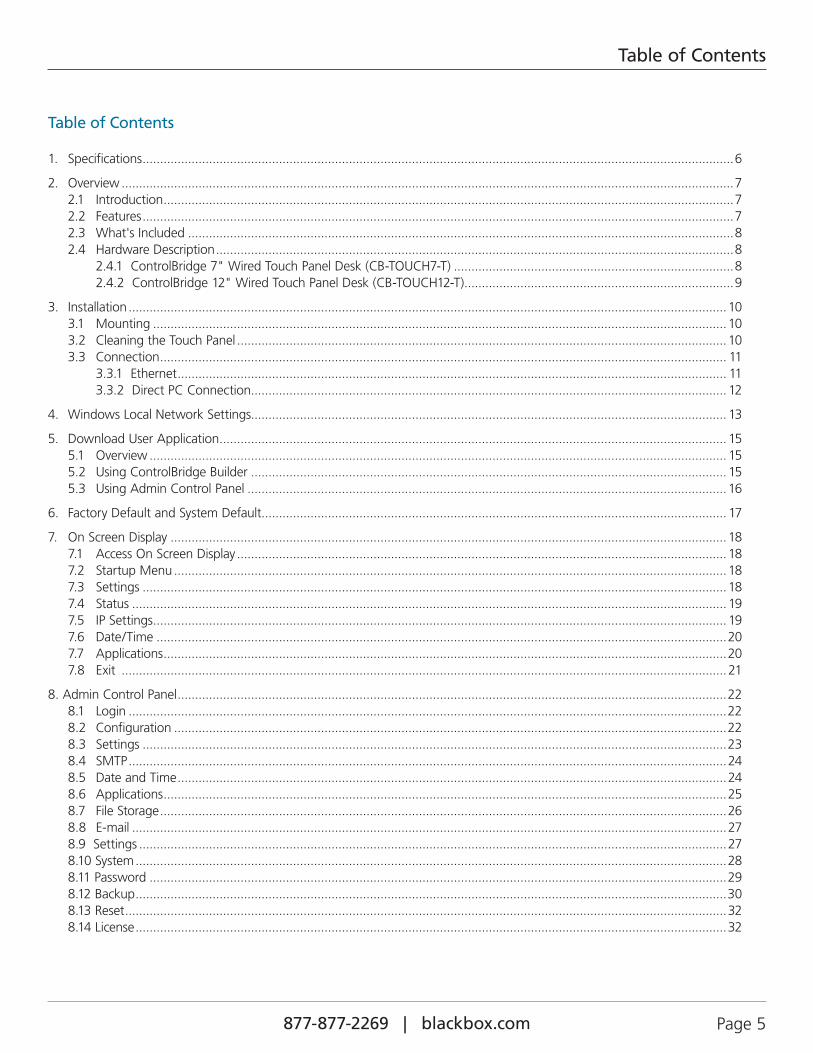
Table of Contents
1. Specifications .........................................................................................................................................................................6
2. Overview ...............................................................................................................................................................................7 2.1 Introduction ...................................................................................................................................................................7 2.2 Features .........................................................................................................................................................................7 2.3 What's Included ............................................................................................................................................................8 2.4 Hardware Description ....................................................................................................................................................8 2.4.1 ControlBridge 7" Wired Touch Panel Desk (CB-TOUCH7-T) ................................................................................8 2.4.2 ControlBridge 12" Wired Touch Panel Desk (CB-TOUCH12-T) .............................................................................9
3. Installation ...........................................................................................................................................................................10 3.1 Mounting ....................................................................................................................................................................10 3.2 Cleaning the Touch Panel ............................................................................................................................................10 3.3 Connection .................................................................................................................................................................. 11 3.3.1 Ethernet ............................................................................................................................................................. 11 3.3.2 Direct PC Connection........................................................................................................................................ 12
4. Windows Local Network Settings........................................................................................................................................ 13
5. Download User Application ................................................................................................................................................. 15 5.1 Overview ..................................................................................................................................................................... 15 5.2 Using ControlBridge Builder ........................................................................................................................................ 15 5.3 Using Admin Control Panel .........................................................................................................................................16
6. Factory Default and System Default ..................................................................................................................................... 17
7. On Screen Display ...............................................................................................................................................................18 7.1 Access On Screen Display ............................................................................................................................................18 7.2 Startup Menu ..............................................................................................................................................................18 7.3 Settings .......................................................................................................................................................................18 7.4 Status ..........................................................................................................................................................................19 7.5 IP Settings ....................................................................................................................................................................19 7.6 Date/Time ...................................................................................................................................................................20 7.7 Applications .................................................................................................................................................................20 7.8 Exit .............................................................................................................................................................................21
8. Admin Control Panel .............................................................................................................................................................22 8.1 Login ...........................................................................................................................................................................22 8.2 Configuration ..............................................................................................................................................................22 8.3 Settings .......................................................................................................................................................................23 8.4 SMTP ...........................................................................................................................................................................24 8.5 Date and Time .............................................................................................................................................................24 8.6 Applications .................................................................................................................................................................25 8.7 File Storage ..................................................................................................................................................................26 8.8 E-mail ..........................................................................................................................................................................27 8.9 Settings ........................................................................................................................................................................27 8.10 System .........................................................................................................................................................................28 8.11 Password .....................................................................................................................................................................29 8.12 Backup .........................................................................................................................................................................30 8.13 Reset ............................................................................................................................................................................32 8.14 License .........................................................................................................................................................................32
877-877-2269 | blackbox.com Page 6
Chapter 1: Specifications
1. Specifications
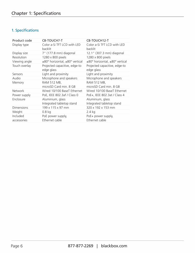
Product code CB-TOUCH7-T CB-TOUCH12-TDisplay type Color a-Si TFT LCD with LED
backlitColor a-Si TFT LCD with LED backlit
Display size 7” (177.8 mm) diagonal 12.1” (307.3 mm) diagonalResolution 1280 x 800 pixels 1280 x 800 pixelsViewing angle ±80° horizontal, ±80° vertical ±80° horizontal, ±80° verticalTouch overlay Projected capacitive, edge-to
edge glassProjected capacitive, edge-to edge glass
Sensors Light and proximity Light and proximityAudio Microphone and speakers Microphone and speakersMemory RAM 512 MB,
microSD Card min. 8 GBRAM 512 MB, microSD Card min. 8 GB
Network Wired 10/100 BaseT Ethernet Wired 10/100 BaseT EthernetPower supply PoE, IEEE 802.3af / Class 0 PoE+, IEEE 802.3at / Class 4Enclosure Aluminium, glass
Integrated tabletop standAluminium, glassIntegrated tabletop stand
Dimensions 199 x 115 x 97 mm 320 x 192 x 153 mmWeight 0.8 kg 2.4 kgIncluded accessories
PoE power supply,Ethernet cable
PoE+ power supply,Ethernet cable
Page 7877-877-2269 | blackbox.com
Chapter 2: Overview
2. Overview
2.1 Introduction
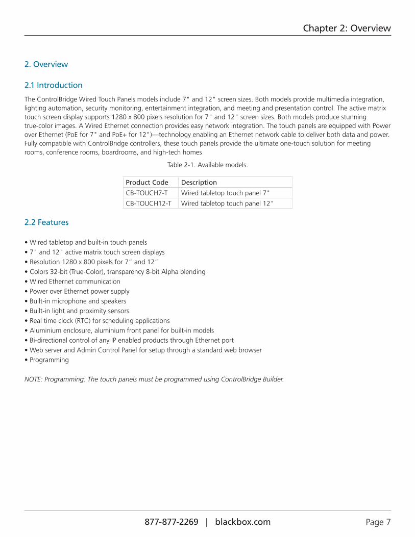
The ControlBridge Wired Touch Panels models include 7" and 12" screen sizes. Both models provide multimedia integration, lighting automation, security monitoring, entertainment integration, and meeting and presentation control. The active matrix touch screen display supports 1280 x 800 pixels resolution for 7" and 12" screen sizes. Both models produce stunning true-color images. A Wired Ethernet connection provides easy network integration. The touch panels are equipped with Power over Ethernet (PoE for 7" and PoE+ for 12")—technology enabling an Ethernet network cable to deliver both data and power. Fully compatible with ControlBridge controllers, these touch panels provide the ultimate one-touch solution for meeting rooms, conference rooms, boardrooms, and high-tech homes
Table 2-1. Available models.
Product Code Description
CB-TOUCH7-T Wired tabletop touch panel 7"
CB-TOUCH12-T Wired tabletop touch panel 12"
2.2 Features
• Wired tabletop and built-in touch panels• 7" and 12" active matrix touch screen displays• Resolution 1280 x 800 pixels for 7” and 12”• Colors 32-bit (True-Color), transparency 8-bit Alpha blending• Wired Ethernet communication• Power over Ethernet power supply• Built-in microphone and speakers• Built-in light and proximity sensors• Real time clock (RTC) for scheduling applications• Aluminium enclosure, aluminium front panel for built-in models• Bi-directional control of any IP enabled products through Ethernet port• Web server and Admin Control Panel for setup through a standard web browser• Programming
NOTE: Programming: The touch panels must be programmed using ControlBridge Builder.
877-877-2269 | blackbox.com Page 8
Chapter 2: Overview
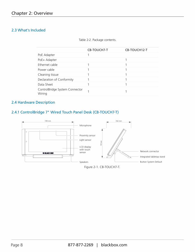
2.3 What's Included
Table 2-2. Package contents.
CB-TOUCH7-T CB-TOUCH12-T
PoE Adapter 1
PoE+ Adapter 1
Ethernet cable 1 1
Power cable 1 1
Cleaning tissue 1 1
Declaration of Conformity 1 1
Data Sheet 1 1
ControlBridge System Connector Wiring
1 1
2.4 Hardware Description
2.4.1 ControlBridge 7" Wired Touch Panel Desk (CB-TOUCH7-T)
102 mm
115
mm
Network connector
Button System Default
Integrated tabletop stand
Speakers
LCD display with touch sensor
199 mm
Microphone
Light sensor
Proximity sensor
Figure 2-1. CB-TOUCH7-T.

Page 9877-877-2269 | blackbox.com
Chapter 2: Overview
2.4.2 ControlBridge 12" Wired Touch Panel Desk (CB-TOUCH12-T)
Speakers
Light sensor
LCD display with touch sensor
320 mm 153 mm
192
mm
Network connector
Microphone
Button System Default
Integrated tabletop stand
Proximity sensors
Figure 2-2.CB-TOUCH12-T.
Table 2-3. CB-TOUCH7-T and CB-TOUCH12-T components.
Component Description
Microphone The microphone is for future use. The functionality depends on a firmware version.
Proximity sensor The Motion sensor resumes touch panel from Backlight Saver mode. Enable/Disable this function using On-Screen Display or Admin Control Panel.
Light Sensor The Light Sensor automatically adjusts display backlight according ambient light level. This function has to be enabled using On-Screen Display or Admin Control Panel.
Touch-screen display Touch-screen display with active matrix color LCD and resistive touch membrane overlay.
Speakers Use the built-in stereo speakers to play sounds stored in the touch panels.
System Default Button When you press this button, the system resets to factory defaults. For details, see ythe Factory Default and System Default chapter. You will need to use a thin screwdriver to press this button.
Network Connector The 10/100BASE-T LAN is a standard network connection equipped with Power over Ethernet an using RJ-45 connector. For more details see the Connection chapter.

877-877-2269 | blackbox.com Page 10
Chapter 3: Installation
3. Installation
3.1 Mounting
Desktop models can be placed on any flat surface. To install, follow these steps:
1. Don’t forget to prepare the proper bushing for the cable including a standard connector. The bushing should have a minimum diameter of approximately 20 mm for the Ethernet connector.
2. Install the network cable as described on the following picture and connect the network connector.
Network connector
Network cable
Figure 3-1. Connecting the ControlBridge WIred Touch Panel to the network.
3. Place the touch panel on a table.
3.2 Cleaning the Touch Panel
Clean the touch panel screen overlay after each day’s use.
You will need:
1 Two clean, soft texture cloths (cotton).
2. Spray bottle of cleaning solution without alcohol (window cleaner).
3. Clean aluminium parts using a special cleaning solution.
Follow these steps:
1. Turn the touch panel off.
2. Spray a small amount of the cleaning solution onto one of the cloths.
3. Clean the touch panel overlay with the damp cloth.
4. Wipe the touch panel overlay with the dry cloth.
Page 11877-877-2269 | blackbox.com
Chapter 3: Installation
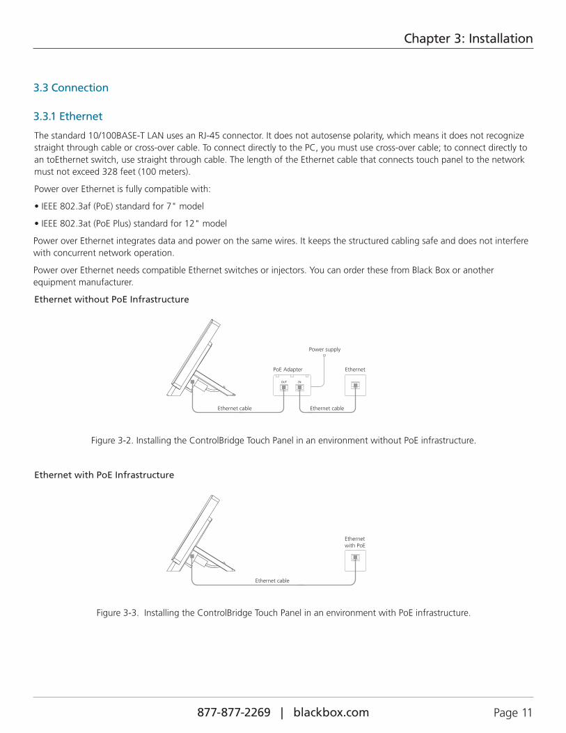
3.3 Connection
3.3.1 Ethernet
The standard 10/100BASE-T LAN uses an RJ-45 connector. It does not autosense polarity, which means it does not recognize straight through cable or cross-over cable. To connect directly to the PC, you must use cross-over cable; to connect directly to an toEthernet switch, use straight through cable. The length of the Ethernet cable that connects touch panel to the network must not exceed 328 feet (100 meters).
Power over Ethernet is fully compatible with:
• IEEE 802.3af (PoE) standard for 7" model
• IEEE 802.3at (PoE Plus) standard for 12" model
Power over Ethernet integrates data and power on the same wires. It keeps the structured cabling safe and does not interfere with concurrent network operation.
Power over Ethernet needs compatible Ethernet switches or injectors. You can order these from Black Box or another equipment manufacturer.
Ethernet without PoE Infrastructure
Power supply
PoE Adapter
OUT IN
Ethernet cable Ethernet cable
Ethernet
Figure 3-2. Installing the ControlBridge Touch Panel in an environment without PoE infrastructure.
Ethernet with PoE Infrastructure
Ethernet cable
Ethernetwith PoE
Figure 3-3. Installing the ControlBridge Touch Panel in an environment with PoE infrastructure.
877-877-2269 | blackbox.com Page 12
Chapter 3: Installation
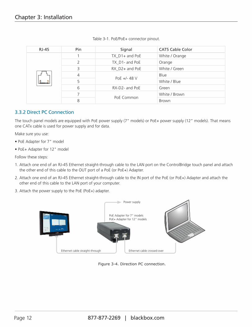
Table 3-1. PoE/PoE+ connector pinout.
RJ-45 Pin Signal CAT5 Cable Color
1 TX_D1+ and PoE White / Orange
2 TX_D1- and PoE Orange
3 RX_D2+ and PoE White / Green
4PoE +/- 48 V
Blue
5 White / Blue
6 RX-D2- and PoE Green
7PoE Common
White / Brown
8 Brown
3.3.2 Direct PC Connection
The touch panel models are equipped with PoE power supply (7” models) or PoE+ power supply (12” models). That means one CATx cable is used for power supply and for data.
Make sure you use:
• PoE Adapter for 7" model
• PoE+ Adapter for 12" model
Follow these steps:
1. Attach one end of an RJ-45 Ethernet straight-through cable to the LAN port on the ControlBridge touch panel and attach the other end of this cable to the OUT port of a PoE (or PoE+) Adapter.
2. Attach one end of an RJ-45 Ethernet straight-through cable to the IN port of the PoE (or PoE+) Adapter and attach the other end of this cable to the LAN port of your computer.
3. Attach the power supply to the PoE (PoE+) adapter.
Power supply
PoE Adapter for 7” modelsPoE+ Adapter for 12” models
Ethernet cable straight-through Ethernet cable crossed-over
Figure 3-4. Direction PC connection.
Page 13877-877-2269 | blackbox.com
Chapter 4: Windows Local Area Network Settings
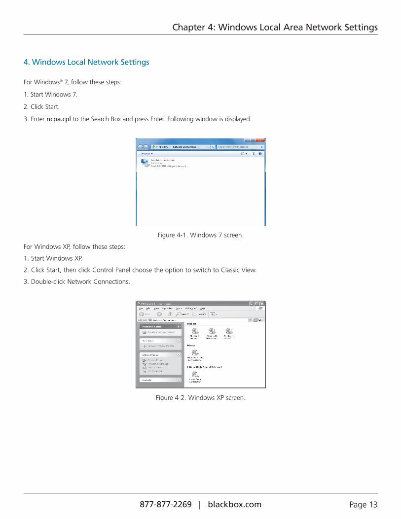
4. Windows Local Network Settings
For Windows® 7, follow these steps:
1. Start Windows 7.
2. Click Start.
3. Enter ncpa.cpl to the Search Box and press Enter. Following window is displayed.
Figure 4-1. Windows 7 screen.
For Windows XP, follow these steps:
1. Start Windows XP.
2. Click Start, then click Control Panel choose the option to switch to Classic View.
3. Double-click Network Connections.
Figure 4-2. Windows XP screen.

877-877-2269 | blackbox.com Page 14
Chapter 4: Windows Local Area Network Settings
Follow these steps:
1. Right-click on the network adapter used to connect to the touch panel and then right-click and select Properties.
2. Select Internet Protocol (TCP/IP) and click the Properties button.
Figure 4-3. General tab.
3. Select the “Use the following IP address” option. Set the IP address to 192.168.1.1 (or another address different from
192.168.1.127 and from 192.168.1.128) and Subnet mask to 255.255.255.0. Leave other options unchanged and click OK.
Figure 4-4. TCP/IP Properites screen.
Page 15877-877-2269 | blackbox.com
Chapter 5: Download the User Application
5. Download the User Application
5.1 Overview
A user control application is dedicated to control and it is programmed by ControlBridge Builder programming tools.
5.2 Using ControlBridge Builder
Follow these steps:
1. Connect the touch panel to your computer as described in the PC Connection chapterr.
2. Run ControlBridge Builder on your PC.
3. Open the appropriate project in ControlBridge Builder. Make sure that the touch panel is properly inserted and configured.
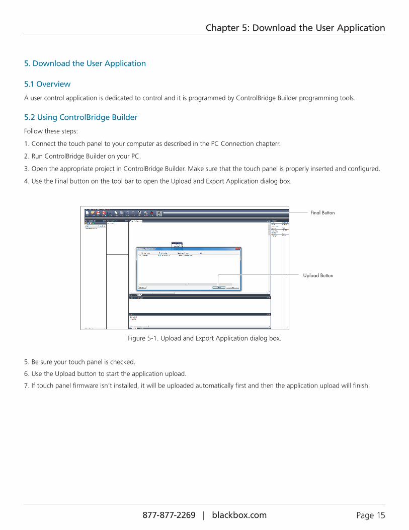
4. Use the Final button on the tool bar to open the Upload and Export Application dialog box.
Figure 5-1. Upload and Export Application dialog box.
5. Be sure your touch panel is checked.
6. Use the Upload button to start the application upload.
7. If touch panel firmware isn’t installed, it will be uploaded automatically first and then the application upload will finish.
Final Button
Upload Button
877-877-2269 | blackbox.com Page 16
Chapter 5: Download the User Application
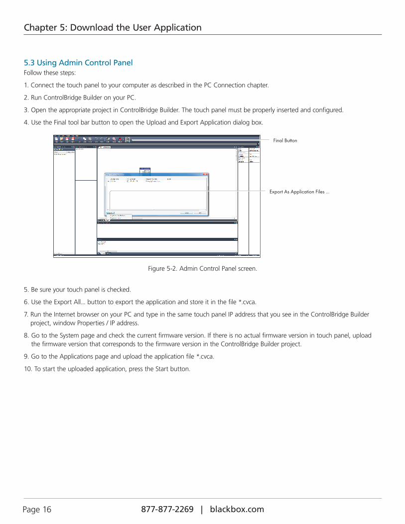
5.3 Using Admin Control PanelFollow these steps:
1. Connect the touch panel to your computer as described in the PC Connection chapter.
2. Run ControlBridge Builder on your PC.
3. Open the appropriate project in ControlBridge Builder. The touch panel must be properly inserted and configured.
4. Use the Final tool bar button to open the Upload and Export Application dialog box.
Final Button
Export As Application Files ...
Figure 5-2. Admin Control Panel screen.
5. Be sure your touch panel is checked.
6. Use the Export All... button to export the application and store it in the file *.cvca.
7. Run the Internet browser on your PC and type in the same touch panel IP address that you see in the ControlBridge Builder project, window Properties / IP address.
8. Go to the System page and check the current firmware version. If there is no actual firmware version in touch panel, upload the firmware version that corresponds to the firmware version in the ControlBridge Builder project.
9. Go to the Applications page and upload the application file *.cvca.
10. To start the uploaded application, press the Start button.
Page 17877-877-2269 | blackbox.com
Chapter 6: Factory Default and System Default Settings
6. Factory Default and System Default Settings
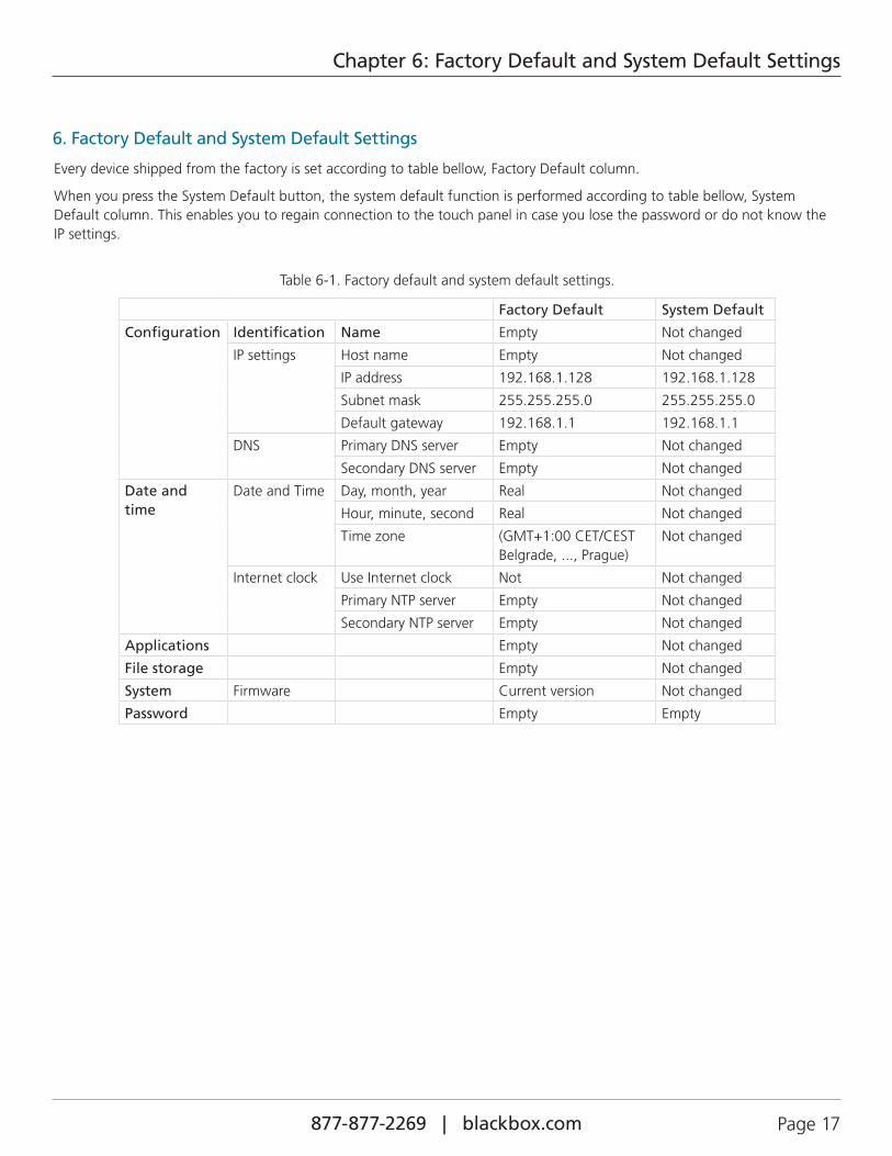
Every device shipped from the factory is set according to table bellow, Factory Default column.
When you press the System Default button, the system default function is performed according to table bellow, System Default column. This enables you to regain connection to the touch panel in case you lose the password or do not know the IP settings.
Table 6-1. Factory default and system default settings.
Factory Default System Default
Configuration Identification Name Empty Not changed
IP settings Host name Empty Not changed
IP address 192.168.1.128 192.168.1.128
Subnet mask 255.255.255.0 255.255.255.0
Default gateway 192.168.1.1 192.168.1.1
DNS Primary DNS server Empty Not changed
Secondary DNS server Empty Not changed
Date and time
Date and Time Day, month, year Real Not changed
Hour, minute, second Real Not changed
Time zone (GMT+1:00 CET/CEST Belgrade, ..., Prague)
Not changed
Internet clock Use Internet clock Not Not changed
Primary NTP server Empty Not changed
Secondary NTP server Empty Not changed
Applications Empty Not changed
File storage Empty Not changed
System Firmware Current version Not changed
Password Empty Empty

877-877-2269 | blackbox.com Page 18
Chapter 7: On-Screen Display
7. On-Screen Display
7.1 Access On Screen Display
The multifunctional button located on front panel shows the On-Screen Display. The Startup Menu is displayed automatically if no application is running.
7.2 Startup Menu
Figure 7-1. Startup Menu.
Press the Application button to download the application.
Press the On Screen Display button to launch the menu described below.
7.3 Settings
1 min
Figure 7-2. Settings menu.
The Backlight Saver automatically switches off the display backlight. Set time in minutes using - and + buttons. Time set to 0 means that Backlight Saver is disabled.
LCD Backlight sets the display backlight level.
If Adaptive Brightness is switched to Yes, the light sensor automatically adjusts the display backlight according to the ambient light level.
If Motion Sensor is switched to Yes, the Motion Sensor automatically resumes touch panel operation from Backlight Saver mode.
Page 19877-877-2269 | blackbox.com
Chapter 7: On-Screen Display
7.4 Status
Figure 7-3. Status screen.
This page shows the current status of the touch panel.
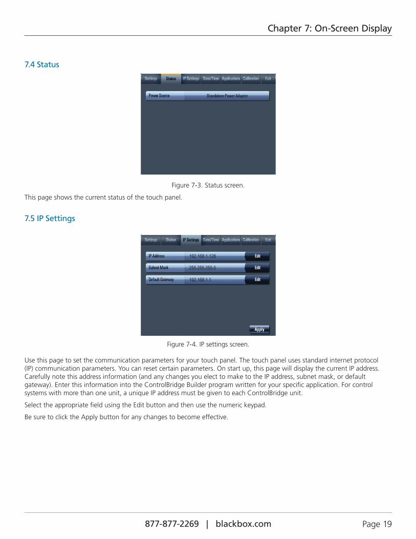
7.5 IP Settings
192.168.1.128
255.255.255.0
192.168.1.1
Figure 7-4. IP settings screen.
Use this page to set the communication parameters for your touch panel. The touch panel uses standard internet protocol (IP) communication parameters. You can reset certain parameters. On start up, this page will display the current IP address. Carefully note this address information (and any changes you elect to make to the IP address, subnet mask, or default gateway). Enter this information into the ControlBridge Builder program written for your specific application. For control systems with more than one unit, a unique IP address must be given to each ControlBridge unit.
Select the appropriate field using the Edit button and then use the numeric keypad.
Be sure to click the Apply button for any changes to become effective.
877-877-2269 | blackbox.com Page 20
Chapter 7: On-Screen Display
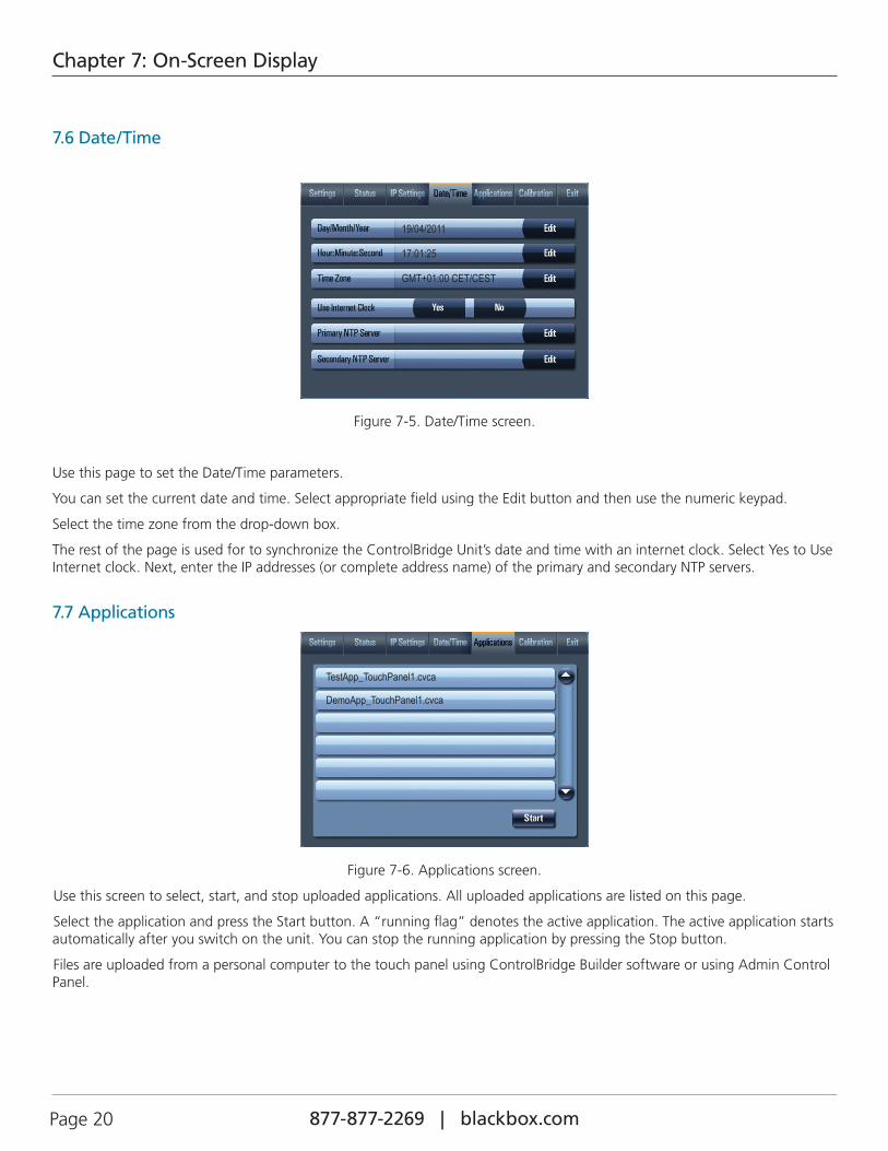
7.6 Date/Time
19/04/2011
17:01:25
GMT+01:00 CET/CEST
Figure 7-5. Date/Time screen.
Use this page to set the Date/Time parameters.
You can set the current date and time. Select appropriate field using the Edit button and then use the numeric keypad.
Select the time zone from the drop-down box.
The rest of the page is used for to synchronize the ControlBridge Unit’s date and time with an internet clock. Select Yes to Use Internet clock. Next, enter the IP addresses (or complete address name) of the primary and secondary NTP servers.
7.7 Applications
TestApp_TouchPanel1.cvca
DemoApp_TouchPanel1.cvca
Figure 7-6. Applications screen.
Use this screen to select, start, and stop uploaded applications. All uploaded applications are listed on this page.
Select the application and press the Start button. A “running flag” denotes the active application. The active application starts automatically after you switch on the unit. You can stop the running application by pressing the Stop button.
Files are uploaded from a personal computer to the touch panel using ControlBridge Builder software or using Admin Control Panel.
Page 21877-877-2269 | blackbox.com
Chapter 7: On-Screen Display
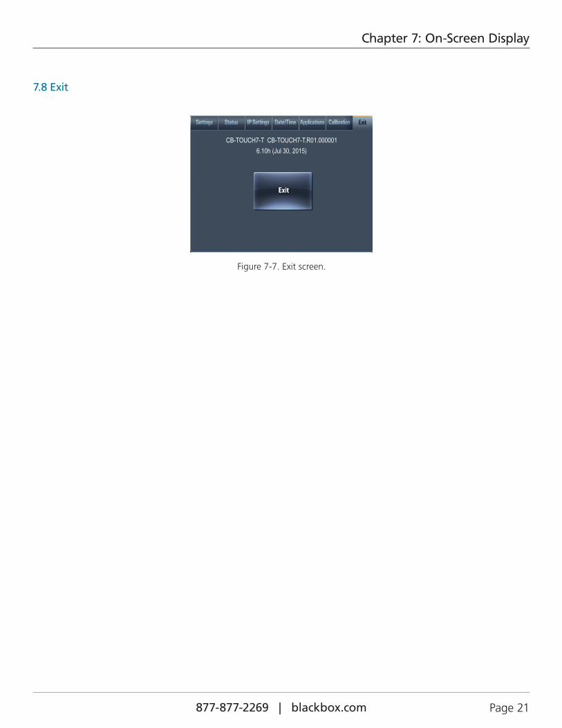
7.8 Exit
CB-TOUCH7-T CB-TOUCH7-T.R01.0000016.10h (Jul 30, 2015)
Figure 7-7. Exit screen.
877-877-2269 | blackbox.com Page 22
Chapter 8: Admin Control Panel
8. Admin Control Panel
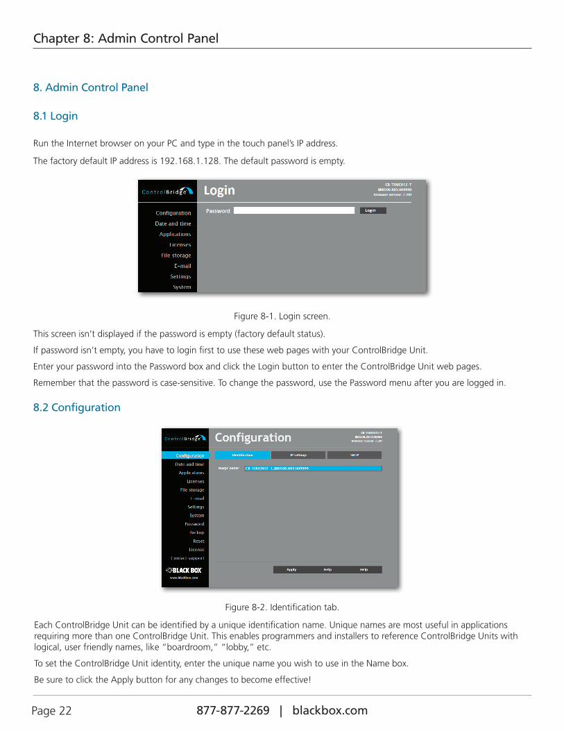
8.1 Login
Run the Internet browser on your PC and type in the touch panel’s IP address.
The factory default IP address is 192.168.1.128. The default password is empty.
Figure 8-1. Login screen.
This screen isn’t displayed if the password is empty (factory default status).
If password isn’t empty, you have to login first to use these web pages with your ControlBridge Unit.
Enter your password into the Password box and click the Login button to enter the ControlBridge Unit web pages.
Remember that the password is case-sensitive. To change the password, use the Password menu after you are logged in.
8.2 Configuration
Figure 8-2. Identification tab.
Each ControlBridge Unit can be identified by a unique identification name. Unique names are most useful in applications requiring more than one ControlBridge Unit. This enables programmers and installers to reference ControlBridge Units with logical, user friendly names, like “boardroom,” “lobby,” etc.
To set the ControlBridge Unit identity, enter the unique name you wish to use in the Name box.
Be sure to click the Apply button for any changes to become effective!

Page 23877-877-2269 | blackbox.com
Chapter 8: Admin Control Panel
B.3 IP Settings
Figure 8-3. Configuration screen.
This page is used for establishing the communication parameters for your ControlBridge Unit.
The ControlBridge Unit uses standard internet protocol (IP) communication parameters. Certain parameters can be reset by the user. On start up, this page will display the ControlBridge Unit’s given Physical address (MAC), Current IP address. Carefully note this addressing information (and any changes you elect to make to the IP address, subnet mask, or default gateway). This information must be entered into the ControlBridge Builder program written for your specific application. For control systems with more than one ControlBridge Units, a unique IP address must be given to each ControlBridge Unit.
Some control systems are “standalone” and not part of a larger network. For such “stand alone” systems, the Host name is optional. However, for control systems that are connected to a larger network, please obtain the Host name from the network administrator, and enter it into the corresponding box. DHCP is not supported in this release.
Be sure to click the Apply button for any changes to become effective!
8.4 SMTP
Figure 8-4. SMTP tab.
Use this page to set SMTP server parameters. Set a name or an address and the port of your SMTP server.

877-877-2269 | blackbox.com Page 24
Chapter 8: Admin Control Panel
The SMTP server and port are used by the XPL2 commands EmailSend and PresetEmailSend.
Be sure to click the Apply button for any changes to become effective!
8.5 Date and Time
Figure 8-5. Current Date and Time.
Use this page to set the time clock on your ControlBridge Unit. The current date, time, and time zone are shown on the Current time line.
Select the applicable boxes to change:
• date: day/month/year,
• time: hour/minute/second.
Be sure to click the Apply button for any changes to become effective!
Figure 8-6. Time zone.
Use this page to set the time zone on your ControlBridge Unit. The current date, time, and time zone are shown on the Current time line. Select the time zone box to change the Time zone.
Page 25877-877-2269 | blackbox.com
Chapter 8: Admin Control Panel
Be sure to click the Apply button for any changes to become effective!
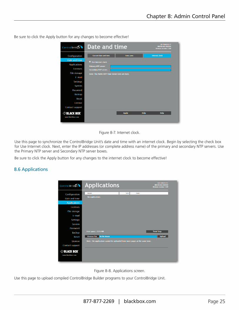
Figure 8-7. Internet clock.
Use this page to synchronize the ControlBridge Unit’s date and time with an internet clock. Begin by selecting the check box for Use Internet clock. Next, enter the IP addresses (or complete address name) of the primary and secondary NTP servers. Use the Primary NTP server and Secondary NTP server boxes.
Be sure to click the Apply button for any changes to the internet clock to become effective!
8.6 Applications
Figure 8-8. Applications screen.
Use this page to upload compiled ControlBridge Builder programs to your ControlBridge Unit.

877-877-2269 | blackbox.com Page 26
Chapter 8: Admin Control Panel
All uploaded applications are listed on this page, along with their file properties: file name/file size/date. The ControlBridge Unit has a generous memory; unused free space is shown at the bottom of this page. ControlBridge Unit also permits other service functions like deleting files, downloading programs back to a personal computer, and starting/stopping specific applications.
A “running flag” denotes the active application. To stop the running application, press the Start/Stop button. To restart the stopped application, press the Start/Stop button.
To upload files from a personal computer to the ControlBridge Unit, select the desired application program and click the Upload button. To download files from the ControlBridge Unit to a personal computer, click the File name. Tp delete files, press the Delete button. Press the Total stop button to stop a running application. This application will not be automatically started after reset.
8.7 File Storage
Figure 8-9. File storage screen.
You can use the ControlBridge Unit’s generous memory as an auxiliary file storage device. This is helpful for storing presets, archiving electronic manuals, pdf files, and other support documentation. Manage the file storage via the file storage page.
A list of existing files, folders, and their properties is shown. To delete a file or a folder, click the Delete button on the correspond-ing line. To delete all files and folders from the current folder, click the Delete All button.
To create a new folder, enter a name for the new folder, and click the Create button. To upload a file, select the desired file, and click the Upload button.
NOTE: Files are automatically compressed for the ControlBridge Unit’s internal file system. Accordingly, the size of your uncom-pressed file before storing may not match the decrease of free space shown on the ControlBridge Unit.
Page 27877-877-2269 | blackbox.com
Chapter 8: Admin Control Panel
8.8 E-mail
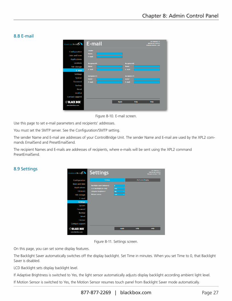
Figure 8-10. E-mail screen.
Use this page to set e-mail parameters and recipients’ addresses.
You must set the SMTP server. See the Configuration/SMTP setting.
The sender Name and E-mail are addresses of your ControlBridge Unit. The sender Name and E-mail are used by the XPL2 com-mands EmailSend and PresetEmailSend.
The recipient Names and E-mails are addresses of recipients, where e-mails will be sent using the XPL2 command PresetEmailSend.
8.9 Settings
Figure 8-11. Settings screen.
On this page, you can set some display features.
The Backlight Saver automatically switches off the display backlight. Set Time in minutes. When you set Time to 0, that Backlight Saver is disabled.
LCD Backlight sets display backlight level.
If Adaptive Brightness is switched to Yes, the light sensor automatically adjusts display backlight according ambient light level.
If Motion Sensor is switched to Yes, the Motion Sensor resumes touch panel from Backlight Saver mode automatically.

877-877-2269 | blackbox.com Page 28
Chapter 8: Admin Control Panel
Figure 8-12. On-screen display.
Set On-Screen Display via this page.
Type of activation is defined here as well as mode of the On Screen Display. In Advanced mode all functions are available, Basic mode is more safety (for example network settings can’t be changed).
IIn addition, you can enable or disable some settings for On-Screen Display.
8.10 System
Figure 8-13. Firmware screen.
Use this page to update the ControlBridge Unit firmware. The Current version of firmware is shown. To upload new firmware, select the desired version and click the Upload button.

Page 29877-877-2269 | blackbox.com
Chapter 8: Admin Control Panel
The page shows basic information about your ControlBridge Unit’s hardware. The CPU type, CPU frequency, and the flash and RAM memory sizes are shown.
Figure 8-14. Format data area.
To completely clear all data and restore factory default settings, click the Format data area button.
This will remove all data, including Applications and File storage files. Configuration will be cleared, including IP address, pass-word, and touch-screen calibration values. IP address will be restored to the default 192.168.1.128.
8.11 Password
Figure 8-15. Password screen.

877-877-2269 | blackbox.com Page 30
Chapter 8: Admin Control Panel
You will need a case-sensitive password to login to the Admin Control Panel pages. Set a new password via the New password box. You must reenter the password in the Confirm new password box. An error message will appear if the confirmation does not match, in this case, reenter your password again in both boxes.
Finally, to implement the new password, click the Apply button.
8.12 Backup
Figure 8-16. Backup screen.
Use this page to backup applications, files and folders. The Backup copies all Applications, Application data, File storage, and Web storage to one archive. This archive is saved to the PC. To start the backup process, click the Backup button.
NOTE: To see the backed-up/restored applications, click the Applications menu. To see backed-up/restored files and folders, click the File Storage menu. Use the page to backup all applications, files, and folders.
NOTE: To see the backed-up/restored applications, click the Applications menu. To see backed-up/restored files and folders, click the File Storage menu.

Page 31877-877-2269 | blackbox.com
Chapter 8: Admin Control Panel
Figure 8-17. Restore screen.
READ ALL IMPORTANT NOTES THAT FOLLOW BEFORE USING THIS OPERATION!The page is used for the restoring of all applications, files and folders. Restore copies of all applications, files, and folders from a backup archive on the PC to their corresponding locations on the ControlBridge Unit.
To start the restore process, select the desired backup archive, then click the Restore button. The restore process can take up to 10 minutes, depending on the size of the files being restored.
If you want ControlBridge Unit’s settings to be restored, too, check the “Restore configuration” box. You can access the ControlBridge Unit’s settings via the Configuration, Date and time, and Password menus.
IMPORTANT NOTE: Actual password and IP settings will be restored, too. The restore process takes from 1 to 10 minutes, depending on the sizes of the restored files.
IMPORTANT NOTE: When restoring files, the running application stops and all applications, files, and folders currently stored in the ControlBridge Unit will be deleted! If you want to retain them, use the Backup command before the Restore command.
NOTE: To see the backed-up/restored applications, click the Applications menu. To see backed-up/restored files and folders, click the File Storage menu.
877-877-2269 | blackbox.com Page 32
Chapter 8: Admin Control Panel
8.13 Reset
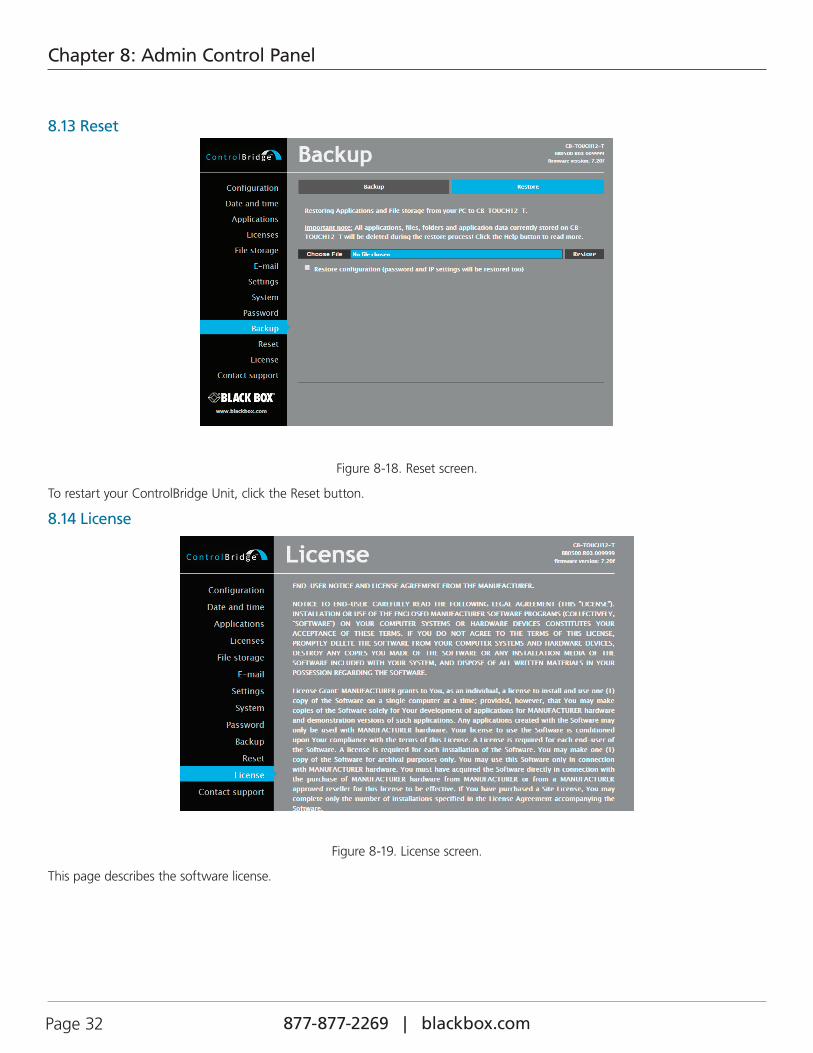
Figure 8-18. Reset screen.
To restart your ControlBridge Unit, click the Reset button.
8.14 License
Figure 8-19. License screen.
This page describes the software license.

Page 33877-877-2269 | blackbox.com
NOTES

877-877-2269 | blackbox.com Page 34
NOTES

Page 35877-877-2269 | blackbox.com
NOTES

877-877-2269 | blackbox.com
About Black BoxBlack Box provides an extensive range of networking and infrastructure products. You’ll find everything from cabinets and racks and power and surge protection products to media converters and Ethernet switches all supported by free, live 24/7 Tech support available in 60 seconds or less.
© Copyright 2016. Black Box Corporation. All rights reserved. Black Box® and the Double Diamond logo are registered trademarks of BB Technologies, Inc. Any third-party trademarks appearing in this manual are acknowledged to be the property of their respective owners.
Black Box Tech Support: FREE! Live. 24/7.
Tech support the way it should be.
Great tech support is just 60 seconds away at 877-877-2269 or blackbox.com.
cb-touch7-t_user_rev1