user manual - toro australia : create a greater outdoors introduction the toro lawn dial outdoor...
TRANSCRIPT
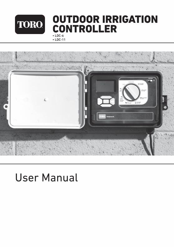
OUTDOOR IRRIGATIONCONTROLLER
User Manual
• LDC-6• LDC-11

2
TABLE OF CONTENTS
Table of Contents
Introduction
The Controller
Introduction to ProgrammingWatering Schedules
Filling Out the WateringSchedule Form
Setting the Time and Date
Setting the Time
Setting the Date
Setting up Watering Programs
Setting Start Times
Setting Watering Days
Setting Station Run Times
Suspending Automatic Watering
Clearing all Programs
Manual Watering
Running a System Test
Running a Program
Rain Sensor
Setting a Rain Delay
2
3
4
5
6
7
7
7
8
8
8
8
10
10
11
12
13
14
14
15
16
16
17
18
18
18
18
19
19
20
21
22
23
Water Budgeting andSeasonal Adjustment
Master Valve On/Off Selection
Pump Delay
Station Delay
Installation Instructions
Mounting the Controller
Electrical Wiring
Wiring the Solenoid Valves
Rain Sensor
Pump Start Relay Connection
Specification
Troubleshooting
Appendix AGuidelines for Watering
Appendix BWatering Schedule Planners

3
INTRODUCTIONThe Toro Lawn Dial Outdoor Irrigation Controller is a programmable electronic timer that controls the watering of six or eleven stations (depending on the model) using remote solenoid valves.
In a typical irrigation system, there is a Master Valve (MV) which is switched on whenever one of the Station Valves (SV) is on.
The Controller is also suitable for use on water supplies derived by pump from a bore or a dam. In this case, the Master Valve control line is used to turn on a Pump Start relay which controls the power to the pump. The Pump Start relay is not supplied with the controller. A Relay should be installed by a qualified electrician.
Note that the Lawn Dial Controller will not power the pump; it will only control an auxiliary relay that switches power to the pump.
Typical Irrigation System
Using a Pump Control Relay
FEATURES
• Easy to install and program.
• 6 individual Programs.
• 6 individual Start Times per Program.
• 3 different watering cycles – day of the week, odd/even days, and interval.
• Water Budget feature which provides easy adjustment of watering for seasonal or weather conditions.
• Rain Sensor function (external sensorrequired) to prevent watering when it has rained.
• Pump delay feature (for use with a bore or dam pump).
• Station delay feature used to prevent or reduce issues caused by slow closing solenoid valves.
• Permanent memory for the retention of all programmed information. In the event of a loss of mains power, data will be saved for up to 5 years. This occurs even if a backup 9V battery is not fitted.
• Battery back-up (9V battery supplied).
• Weather resistant controller with 240VAC power lead and plug.

4
THE CONTROLLERThe Controller has the following features, which will be explained in detail throughout thismanual:
used to select functions:
• OFF stops irrigation
• AUTO RUN automatically run watering programs
• SET CLOCK/CALENDAR set the date and time
• SET START TIMES set the watering start times
• SET WATERING DAYS set the days that watering is to occur
• SET STATION RUN TIMES set the durations of programmed watering
• SET AUXILIARIES
- Rain Sensor turn on/off the rain sensor function
- Main Valve/Pump Start
- Pump DelayTurns the pump on first and then the station after a delay, allowing for pressure to build.
- Station Delay Delays the opening of the next station on sequence to give time for the previous sta-tion to close. Useful for slow to close valves.
• SYSTEM TEST or RUN SINGLE STATION
• RUN PROG.
Control Dial
LCD Display
Control Buttons Backup Battery, Control Wiring Terminals
used to navigate through the programming Sequences
(beneath a cover)
Control Panel
Note: If the mains power to the unit is off, to conserve battery energy, the LCD display automatically switches off after about 15 seconds of operator inactivity. Press to see the display again. When mains power is off, the controller does not run the automatic programs, but the clock/calendar and all program information is retained
LCD Display
ControlButtons
Backup Battery andControl Wiring Terminals
Control DialRain Sensor
Switch
5
INTRODUCTION TO PROGRAMMING WATERING SCHEDULES
When programming the controller, there are the following to consider:
STATIONS OR ZONESyour controller has either six (6) or eleven (11) Stations, depending on the model. Each Station has a group of sprinklers in a specific portion (Zone) of the garden and is controlled by a solenoid Valve. Zones are generally laid out according to the type of plant material being watered and the type and flow rate of the
sprinklers used to distribute the water.
PROGRAMSup to six (6) watering Programs can be set and applied to any of the Stations. For each Program, the following are programmable:
• Watering Days watering may be programmed to occur on
- fixed days of the week (eg. Mon, Wed and Fri),
- at intervals of a number of days (eg. every third day), or
- on odd or even days of the month (eg. 1st, 3rd, 5th, 7th etc.)
• Start Time each program may have up to six (6) Start Times
• Run Time each Station (or Zone) has an associated Run Time
Programming is a lot easier if you first fill out a Watering Schedule Form, an example of which is on the next page. You will have a record of your watering schedule and zone locations which can be kept with your controller. In theexample, four Programs have beenprogrammed:
• Program 1 starts at 7:00am on Mondays and Thursdays and runs for 20 minutes on Stations 1, 2, 3, 5 and 6
• Program 2 starts at 9:00pm every day and runs for 10 minutes on Stations 3 and 6. Note that if no Watering Days are programmed, the Lawn Dial Controller defaults to every day
• Program 3 starts at 6:00am every third day and runs for 10 minutes on Station 4 only
• Program 4 starts at 5:00am on Tuesdays and Sundays and runs for 30 minutes on Station 6 only.
Note: The Controller runs all programmedwatering sequentially, with only one Valve open at any given time. In the example, Program 1 will water Station 1, then Station 2, then Station 3, then Station 5 and then Station 6, beginning at 7:00am, and taking a total time of 100 minutes.
If another Program was scheduled to start at say 8:00am, it would be delayed until 8:40am (the completion of Program 1).Therefore, when scheduling multiple programsand/or multiple start times within eachprogram, make sure that each program cycle can run to completion before the next program cycle is scheduled to start. If you do not do this, the Controller will automatically stack them in sequence.

6
FILLING OUT WATERING SCHEDULE FORMVALVE NUMBERIn the area at the top of the form, fill in the area and/or type of lawn or garden which is to be watered by each Valve. In the example, three of the valves are watering turf (lawn), two are watering flowers and one is watering vegetables.
WATERING DAYSFor each Program (1 to 6), write in the days of the week that watering is required (eg. Mon, Wed, Fri), or the interval between waterings (eg. 3 days – water every third day), or Odd or Even if restricted watering is imposed, based on your house number.
RUN TIME (minutes)For each of the Programs and each of theStations, write in the Run Time required. Run time can be set to any time between 1 minute and 12 hours and 59 minutes.
START TIMEWrite in the Start Times for each of the six Programs. Each program can have up to six assigned start times.
Sample Six Station Watering Schedule Form

7
SETTING THE TIME AND DATE
1 Select Set Clock/Calendar on the Control Dial. This will cause the HOUR to flash.
2 Use the and buttons to adjust the hour to the correct value. Note that the clock is 12 hour so ensure that the correct AM or PM is displayed.
3 Press and MIN will flash.
4 Use the and buttons to adjust the minutes to the correct value.
1 Select Set Clock/Calendar on the Control Dial. This will cause the HOUR to flash.
2 Press and DAY will flash.
3 Use the and buttons to adjust the day to the correct value.
4 Press and MONTH will flash.
5 Use the and buttons to adjust the month to the correct value.
6 Press and YEAR will flash.
7 Use the and buttons to adjust the year to the correct value.
PM 9: 27HOUR MIN
TUE
DAY
2015YEAR MONTH
TUE
9 15ODD
Note: If the 9V backup battery is not fitted, or is flat, when mains power is lost, the controller memory updates every 10 minutes. When power is restored, the clock resumes at the last updated time, which may differ from the correct time by up to 10 minutes.
Control Switch
SETTING THE TIME SETTING THE DATE

8
SETTING UP WATERING PROGRAMSUp to six Programs may be entered, each requiring the programming of:
• Watering days – applied to all Station numbers and Start Times• Start times – up to six• Station numbers - up to four or six, depending on the model• Station Run Times – may be different for each Station
For example, Program 3 may be set to water on Mondays and Thursdays (Watering Days), at 7am and 7pm (Start Times), and water Station 1 for 20 minutes, Station 2 for 10 minutes, and Station 4 for 30 minutes (Run Times).
An example of the use of six start times is the watering of a new lawn in very hot weather. It might be watered for 10 minutes at 6am, 10am, 1pm, 3pm and 5pm.
SETTING START TIMES
SETTING WATERING DAYS
1 Select SET START TIMES on the Control Dial. This will cause the START No to flash.
2 Press to select the required Program.3 Use and to select the Start No
required.
4 Press and OFF will flash (if a start time has previously been set, then the Hours will flash.
5 Use and to select the Start Time Hours required.
6 Press and MIN will flash.
7 Use and to select the Start Time Minutes required.
8 To add a second start time, press until Start Number 1 flashes, press to change start number to 2. Repeat steps 4-7 for Start Number 2
9 Repeat steps 2 to 7 until all Start Times have been programmed for all Programs.
PROGNo
3START
No
1AM7: 30HOUR MIN
There are three ways to set Watering Days:
• Calendar Schedule water on specific days of the week (eg. Monday, Wednesday and Friday). This is a seven day schedule which starts on Monday and ends on Sunday.• Interval Schedule water at intervals of a selected number of days (eg. every third day). Available intervals are from 1 (water every day) to 15 (water every 15th day).• Odd/Even Schedule water on odd or even numbered days of the month (useful in times of drought when watering restrictions are in place).

9
SETTING UP WATERING PROGRAMSTo program Watering Days:
1 Select SET WATERING DAYS on the Control Dial. One of three screens will appear. On the first screen, one of the days of the week will be flashing. On the second screen, ODD may be replaced by EVEN. On the third screen, INTERVAL DAYS is displayed.
2 Press until PROG No indicates the desired program (1, 2, 3, 4, 5 or 6).
3 Press or to move to the appropriate screen.
a. To select specific Watering Days, press until MON is flashing. Press if watering is required on Monday, or press if it is not. Repeat for each of the other days of the week. When a day has been deselected, it will no longer be displayed. Only those days when watering is to occur will be displayed.
b. To select ODD or EVEN, press or until the desired ODD or EVEN is displayed.
c. To select a watering Interval, press until the number of INTERVAL DAYS is flashing. Press or until the desired number is displayed. The interval may be any number of days from 1 to 15.Then press , the lefthand number will flash. Press or to change this number to reflect the current day in the cycle. For example if set to 0 with a 4 day interval, the next irrigation would occur in 3 days. If set to 2 in a 3 day interval the next irrigation would occur a day later.
4 Repeat steps 2 and 3 until Watering Days have been programmed for all Programs.
MON WED FRI SUN
1No
PROG
PROG
No
1ODD
DAYS
PROG
No
1INTERVAL DAYS
30WATER
No

10
SETTING UP WATERING PROGRAMS
SETTING STATION RUN TIMES
SUSPENDING AUTOMATIC WATERING
CLEARING ALL PROGRAMS
The Station Run Time is the length of time the Station will water during the programmed watering cycle. Run times can be set from 0 (off) to 12 hours, 59 minutes, in one-minute increments.
A Station is assigned to a Program when it is given a run time. If the run time for a Station is set to zero (0:00) in a program, that Station will not be watered in that Program.
To stop all automatic watering cycles, turn the Control Dial to OFF. The display will show ALL OFF.
All programmed information will be retained and the clock will continue to run.
To resume the programmed watering schedules, turn the Control Dial to AUTO RUN. Irrigation will begin from the next scheduled start time.
All programmed information can be cleared.
1 Select AUTO RUN on the Control Dial.
2 Press and hold the , , and buttons simultaneously for 5 seconds.
This removes all programming but does not reset the clock and calendar.
In the example below, Program 1 has been set to water Station 2 for 30 minutes.
1 Select SET STATION RUN TIMES on the Control Dial. This will cause the Station No to flash.
2 Use the button to select the Program required.
3 Use the and buttons to select the Station number.
4 Press and HOUR will flash. Use the and buttons to set the number of hours ofwateringrequired on that Station. Typically, this will be 0, but could be up to 12.
5 Press and MIN will flash. Use the and buttons to set the number of minutes of watering required on that Station.
6 Repeat steps 2 to 5 until all Station Run Times have been programmed for all Programs.
HOUR0: 30
STATION No
MIN
RUN TIME
2PROG
No
1

11
MANUAL WATERINGA single selected Station can be watered for a selected period of time.
1 Select SYSTEM TEST or RUN SINGLE STATION on the Control Dial. The Station Number will flash.
2 Use the and buttons to select the Station to be run. RUN TIME can be set to any time between 1 minute and 12 hours and 59 minutes
3 Press and RUN TIME HOUR will flash. Use the and buttons to select the number of hours that you want to water.
4 Press and RUN TIME MIN will flash. Use the and buttons to select the number ofminutes that you want to water.
5 Press to start watering the selected Station for the selected time.
The display will countdown the time remaining.
To stop watering at any time before the end of the selected period, turn the Control Dial to OFF.
HOUR1: 00
STATION No
MIN
STATIONSINGLE
RUN TIME
2

12
RUNNING A TEST SYSTEM
To test multiple Stations:
1 Select SYSTEM TEST or RUN SINGLE STATION on the Control Dial. SINGLE STATION will be displayed in the bottom left corner of the screen.
2 Press and together. The display inthe bot tom left corner will change to MULTI STATION.
3 Press or to select a Station to test.
4 Press to move to the RUN TIME for the Station.
5 Press or to adjust the Run Time.
6 Press until the Station number is flashing and repeat steps 3 to 5 to program all Stationsto be tested.
7 Press to start the system test.
Each Station with a Run Time set will water in sequence, beginning with the one displayed when was pressed.
Make sure that any valve that you don’t want to test has a runtime of 00min
To stop the test at any time, turn the Control Dial to OFF.
1No RUN TIME
STATION
MIN
MULTI STATION
01
The system may be tested by setting selected stations to water for short times. For example, you might set Station 2 to water for 2 minutes, or multiple Stations 1, 2 and 3 to water for 1 minute each
To test a single Station:
1 Select SYSTEM TEST or RUN SINGLE STATION on the Control Dial. SINGLE STATION will be displayed in the bottom left corner of the screen.
2 Press or to select a Station to test.
3 Press to move to the RUN TIME for the Station.
4 Press or to adjust the Run Time.
5 Press to start the system test. Remainingruntime will be dispalyed on the screen
2No RUN TIME
STATION
MIN
SINGLESTATION
02

13
RUNNING A PROGRAMTo manually start a single Program or a number of Programs:
1 Select RUN PROG. on the Control Dial. A Program number will be displayed and OFF will be flashing.
2 Press to change to ON.
3 Press to select another of the sixprograms and press to change to ON.
4 Repeat step 3 until all desired Programs have been turned on.
5 Press to run the test program. The watering cycles that you have programmed for the selected Programs will begin immediately, regardless of the Start Time and Watering Days programmed.
The controller will run all the activated programs sequentially.
If a Water Budget has been programmed, it will be applied to the watering times.
The test can be stopped temporarily for 10 minutes:
1 Press to pause irrigating. A countdown clock will show the time remaining before the irrigation will resume.
2 Press at any time, to restart the process
O4No
PROG
FF
:34No No RUN TIME
STATION PROG
MIN
PUMPSTATION
24
H 9:OLdMIN SECS
59
14
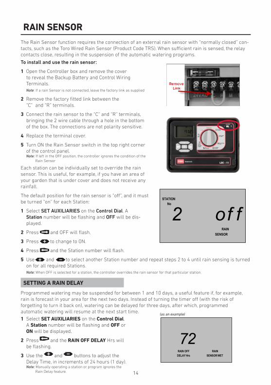
RAIN SENSORThe Rain Sensor function requires the connection of an external rain sensor with “normally closed” con-tacts, such as the Toro Wired Rain Sensor (Product Code TRS). When sufficient rain is sensed, the relay contacts close, resulting in the suspension of the automatic watering programs.
To install and use the rain sensor:
1 Open the Controller box and remove the cover to reveal the Backup Battery and Control Wiring Terminals.Note: If a rain Sensor is not connected, leave the factory link as supplied
2 Remove the factory fitted link between the “C” and “R” terminals.
3 Connect the rain sensor to the “C” and “R” terminals, bringing the 2 wire cable through a hole in the bottom of the box. The connections are not polarity sensitive.
4 Replace the terminal cover.
5 Turn ON the Rain Sensor switch in the top right corner of the control panel.Note: If left in the OFF position, the controller ignores the condition of the
Rain Sensor
Each station can be individually set to override the rain sensor. This is useful, for example, if you have an area of your garden that is under cover and does not receive any rainfall.
The default position for the rain sensor is “off”, and it must be turned “on” for each Station:
1 Select SET AUXILIARIES on the Control Dial. A Station number will be flashing and OFF will be dis-played.
2 Press and OFF will flash.
3 Press to change to ON.
4 Press and the Station number will flash.
5 Use and to select another Station number and repeat steps 2 to 4 until rain sensing is turned on for all required Stations.Note: When OFF is selected for a station, the controller overrides the rain sensor for that particular station.
Programmed watering may be suspended for between 1 and 10 days, a useful feature if, for example, rain is forecast in your area for the next two days. Instead of turning the timer off (with the risk of forgetting to turn it back on), watering can be delayed for three days, after which, programmed automatic watering will resume at the next start time.
o2No
STATION
RAINSENSOR
f f
1 Select SET AUXILIARIES on the Control Dial. A Station number will be flashing and OFF or ON will be displayed.
2 Press and the RAIN OFF DELAY Hrs will be flashing.
3 Use the and buttons to adjust the Delay Time, in increments of 24 hours (1 day).Note: Manually operating a station or program ignores the
Rain Delay feature.
2RAIN OFF RAIN
DELAY Hrs SENSOR WET
7
SETTING A RAIN DELAY
(as an example)

15
WATERING BUDGET AND SEASONAL ADJUSTMENTChanges in season and temperature generally require a change in watering run times to maintain a healthy landscape and conserve water.
The season adjust feature enables you to change simultaneously, all programmed Run Times, in steps of 10%, from 10% of the programmed times up to 200%. The programmed Water Budget is applied to all Stations and all Programs.
A 50% setting, for example, would decrease a 20 minute Station run time to 10 minutes and a 200% setting would double it to 40 minutes.
1 Select AUTO RUN on the Control Dial. The time of day will be displayed.
2 Press and the WATER BUDGET % will be flashing.
3 Use the and buttons to adjust the budget up or down from 100%.
4 Press to display the clock. The screen also now displays the WATER BUDGET %.
16
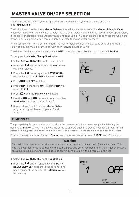
1 Select SET AUXILIARIES on the Control Dial.
2 Press the button repeatedly until PUMP DELAY BETWEEN appears in the bottom right hand corner of the screen. The Station No will be flashing
MASTER VALVE ON/OFF SELECTIONMost domestic irrigation systems operate from a town water system, or a bore or a dam(see Introduction).
The irrigation controller has a Master Valve output which is used to control a Master Solenoid Valve when operating with a town water supply. The use of a Master Valve is highly recommended, particularly if the pipe connections to the Station Valves are done using PVC push on and clip connections which are prone to bursting open when continuously subjected to mains water pressure.
When using water from a bore or a dam, the Master Valve control line is used to control a Pump Start Relay. The pump must be turned on with each individual Station Valve.
The default setting for the Master Valve is OFF. It must be turned ON for each individual Station.
To program the Master/Pump Start valve:
1 Select SET AUXILIARIES on the Control Dial.
2 Press the button once and the PEr screen will be displayed.
3 Press the button again and STATION No will be flashing and PUMP will show as OFF.
4 Press and OFF will flash.
5 Press to change to ON. Pressing will return to OFF.
6 Press and the Station No will flash.
7 Use the and buttons to select another Station No and repeat steps 4 and 5.
8 Repeat steps 6 and 7 until all Master Valve programming has been completed for all Stations.
PUMP DELAY
The pump delay feature can be used to allow the recovery of a bore water supply by delaying the opening of Station valves. This allows the pump to operate against a closed head for a programmed period of time, pressurizing the main line. This can be useful where draw down can occur in a bore.
Different delays can be set for each Station and the value can be between 0 (OFF) and 99 seconds.
WarningThis irrigation system allows the operation of a pump against a closed head (no valves open). This has the potential to cause damage to the pump, pipes and other components in the irrigation system, resulting in explosion, and should be used only in consultation with a hydraulic engineer.
O1No
STATION
PUMPDELAY BETWEEN
FF

17
1 Select SET AUXILIARIES on the Control Dial.
2 Press the button repeatedly until STATION DELAY appears in the bottom left hand corner of the screen. The Station No will be flashing.
3 Use the and buttons to select the required Station No.
4 Press and OFF will flash.
5 Press repeatedly until the required delay time is reached (1 to 99 seconds). Setting the time to 0 or 100 will reset the delay to OFF.
6 Press and the Station No will flash.
7 Repeat steps 4 to 6 until the delay has been set for all required Stations.
MASTER VALVE ON/OFF SELECTION3 Use the and buttons to select the
required Station No.
4 Press and OFF will flash.
5 Press repeatedly until the required delay time is reached (1 to 99 seconds). Setting the time to 0 or 100 will reset the delay to OFF.
6 Press and the Station No will flash.
7 Repeat steps 4 to 6 until the delay has been set for all required Stations.
:2No
STATION
SECSPUMPDELAY BETWEEN
30
STATION DELAY
Station delay is used to reduce complications caused if one valve is slow to close and the next valve opens before that valve has closed. Station delay adds a short delay in valve operation, meaning the next valve in the watering sequence is opened slightly after the previous one is closed.
Different delays can be set for each Station and the value can be between 0 (OFF) and 99 seconds.
O2No
STATION
DELAYSTATION
FF
:2No
STATION
SECS
DELAYSTATION
10
18
INSTALLATION INSTRUCTIONS
MOUNTING THE CONTROLLER WIRING THE SOLENOID VALVES
ELECTRICAL WIRING
As the Controller comes with a 1.0m fixed power lead, select a location for the Controller within 0.9m of an outdoor electrical outlet.
For safe, reliable operation, select an installation site which will provide the following conditions:
• Protection from irrigation spray, exposure to wind, heavy rain, snow and direct sun during the hottest part of the day. The controller is intended for use outdoors and can be exposed to light rain as it is weather resistant.
• Access to a grounded power source which is not controlled by a light switch or utilized by a high current load appliance, such as a refrigerator or air conditioner.
• Access to the sprinkler control valve wiring and optional accessory wiring.
Using two screws, fix the controller to a wall using the keyhole slot on the top centre of the back of the weatherproof box, and the hole at the bottom under the terminal cover.
WarningHigh voltage (240V) electrical work must be
carried out by a licensed electrician. Failure to do so will void the Controller warranty.
If the Controller is located outside, do not use a power extension lead to reach a power point
more distant than 0.9m.
When the irrigation system is used on a town water supply, the only high voltage wiring needed is the provision of an electrical outlet to supply power to the Controller. Alternatively, the controller can be hard-wired to a 240V circuit. If the Controller is located outside, a suitable external power outlet is required.
If the system is used on a bore or dam water supply and a pump start relay is required, all 240V electrical work must be carried out by a qualified electrician.
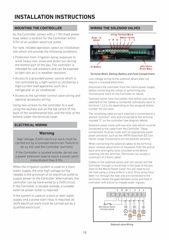
Terminal Block, Backup Battery and Fuse Compartment
Low voltage wiring to the solenoid valves does not require a licensed electrician.
Disconnect the controller from the mains power supply before connecting the valves or performing anymaintenance work on the Controller or valves.
Solenoid valves have two cables. One (either one can be selected) of the cables is connected individually back to terminal 1,2,3,4, eta depending on the assigned station number for the valve.
The remaining cable on each solenoid is connected to a shared “common” wire and connected to the terminal marked “C” on the controller (see diagram below)
Solenoid valves come with two wire tails which must be connected to the cable from the Controller. Theseconnections must be made with an appropriate water proof connector, such as the 3MTM Scotchlok IDC Con-nector range. Connections are not polarity sensitive.
When connecting the solenoid cables to the terminal block, remove about 6mm of insulation from the end of each wire and tightly twist stranded wires beforeinserting into the terminal. (Terminals can accept a maximum of 2.5mm cable)
Cables to the solenoid valves and rain sensor exit the Controller through a round hole in the base of the box (next to the Mains Power Cord). You will need to cut the hole using a sharp knife or a drill. Once wires have been run through the hole and are connected to the terminals, reseal the gaps between wires and hole in controller with silicon to impede water ingress.
Solenoid valve Wiring
C R M 1 2 3 4
SV4
SV3
SV2
SV1
MV
Rain Sensor Switch(normaly closed)

19
INSTALLATION INSTRUCTIONS
RAIN SENSOR PUMP START RELAY CONNECTION
The controller is factory fitted with a link be-tween terminals R and C. If a Rain Sensor is not to be used, then leave this link in place.
If a Rain Sensor is to be used, then remove this link and connect the rain Sensor to terminals R and C. The Rain Sensor must have normally closed contacts that open when sufficient rain is sensed.
NOTEThe solenoid valve outputs are 24VAC and
designed to operate a maximum of twosolenoid valves per station. Station current
draw not to exceed 0.5 amps. Maximum combined current draw including the master valve/pump start relay and station shall not
exceed 0.8 amps.
Exceeding the maximum current draw may damage the controller and void the warranty.
CAUTIONThe controller cannot be used to power a
pump motor directly. As shown in the drawing below, the controller provides 24VAC
(maximum current 0.5A) to switch an auxiliary relay which switches power to the pump.
CAUTIONTo prevent pump damage due to “dead-head-ing” (the pump is running, a station has inad-vertently been given a run time but no valve is connected to the output terminal), connect
a jumper wire from any unused station termi-nals to a used station terminal, as shown by
the red arrow in the above diagram.
Note: In the instance shown in the diagram above, station 3 will be activated when the
controller activates station 4
Pump Start Wiring

20
SPECIFICATIONSCabinet Dimensions240mm x 80mm x 185mm
Power SpecificationsInternal TransformerInput: IN: 230/240VAC 50Hz
Output: OUT: 24VAC
Max Station load 0.3A
Total Master Valve Load 0.5A
Total Maximum Load 0.8A
Surge Protection47KV normal mode
Battery Type9 volt
Operating Temperature range0-60°C
IP RatingIP44
Maximum Cable size0.5mm - 2.54mm²
Warranty1 Year
21
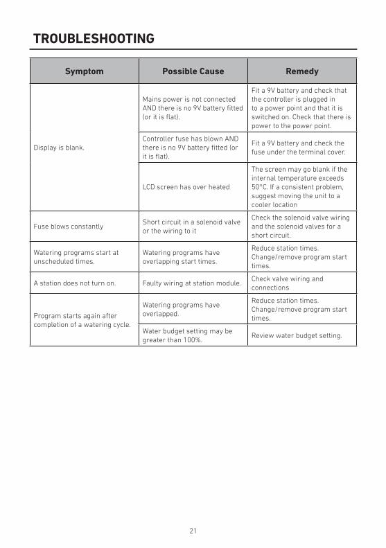
TROUBLESHOOTING
Symptom Possible Cause Remedy
Display is blank.
Mains power is not connected AND there is no 9V battery fitted (or it is flat).
Fit a 9V battery and check that the controller is plugged in to a power point and that it is switched on. Check that there is power to the power point.
Controller fuse has blown AND there is no 9V battery fitted (or it is flat).
Fit a 9V battery and check the fuse under the terminal cover.
LCD screen has over heated
The screen may go blank if the internal temperature exceeds 50°C. If a consistent problem, suggest moving the unit to a cooler location
Fuse blows constantlyShort circuit in a solenoid valve or the wiring to it
Check the solenoid valve wiring and the solenoid valves for a short circuit.
Watering programs start at unscheduled times.
Watering programs haveoverlapping start times.
Reduce station times.Change/remove program start times.
A station does not turn on. Faulty wiring at station module.Check valve wiring andconnections
Program starts again after completion of a watering cycle.
Watering programs haveoverlapped.
Reduce station times.Change/remove program start times.
Water budget setting may be greater than 100%.
Review water budget setting.
22
APPENDIX A - GUIDELINES FOR WATERING
WARRANTY
When deciding how much to water a garden or lawn, there are several factors to be considered:
• Soil type – clay, sand, silt, or a mixture of them
• Slope of the ground – does the water run off
• Type of grass or plants – the water needs of plants vary greatly
• Exposure to sun and shade – how much sun and at what time of day
• The rate at which water is applied – determined by the water pressure and the type ofwatering nozzle used
• Time of day that watering takes place – the best time to water is one to two hours before sunrise
It is therefore difficult to devise the perfect watering schedule and some trial and error will be required before you settle on the best schedule.
Here are some general watering hints to help you get started:
• Water early in the morning, one to two hours before sunrise, when the water pressure is highest and evaporation is lowest and the water can soak into the plant root zone. Watering during generally mid-day or in the evening may cause plant damage.
• Newly planted lawns, until established, should be watered frequently for short durations to keep the soil and plants moist at all times
• Reduce watering duration and water more frequently if water run off is occurring.
• Water an established landscape enough to saturate the soil without causing runoff.
• When starting a new watering program, gradually decrease watering over a period of time until youbegin to notice signs of plant stress caused by lack of water, then increase watering a little to regain plant health and vitality. This method enables a healthy landscape to be maintained using the least amount of water.
This product has a 1 Year manufacturer’s guarantee against defects in material and workmanship when used for its intended purpose. Our obligation under this guarantee is limited to the repair or replacement of the product at our discretion for the period stated. In the event of a claim, you must immediately cease using the product and return the product, together with your proof of purchase and an explanation of the fault to the store you purchased it from. All costs associated with the return of the product are the purchasers’ responsibility. To process the warranty, the retailer must contact Toro Australia via their representative or the phone number listed below.
Our goods come with guarantees that cannot be excluded under the Australian Consumer Law. You are entitled to a replacement or refund for a major failure and for compensation for any other reasonably foreseeable loss or damage. You are also entitled to have the goods repaired or replaced if the goods fail to be of acceptable quality and the failure does not amount to a major failure.
Toro Australia Pty Ltd53 Howards Road, Beverley SA [email protected] 130 898toro.com.au

23
APPENDIX B - WATERING SCHEDULE PLANNERS
VALVE NUMBER
1 7
2 8
3 9
4 10
5 11
6
PR
OG
RA
M
PR
OG
RA
MSTART TIME
WATERINGDAYS S
TAT
ION
RUN TIME(minutes)
START TIMEWATERING
DAYS STA
TIO
N
RUN TIME(minutes)
1
2
3
4
5
6
7
8
9
10
11
1
Start Time 1:
Start Time 2:Start Time 3:Start Time 4:Start Time 5:Start Time 6:
1
2
3
4
5
6
7
8
9
10
11
4
Start Time 1:
Start Time 2:Start Time 3:Start Time 4:Start Time 5:Start Time 6:
1
2
3
4
5
6
7
8
9
10
11
2
Start Time 1:
Start Time 2:Start Time 3:Start Time 4:Start Time 5:Start Time 6:
1
2
3
4
5
6
7
8
9
10
11
5
Start Time 1:
Start Time 2:Start Time 3:Start Time 4:Start Time 5:Start Time 6:
1
2
3
4
5
6
7
8
9
10
11
3
Start Time 1:
Start Time 2:Start Time 3:Start Time 4:Start Time 5:Start Time 6:
1
2
3
4
5
6
7
8
9
10
11
6
Start Time 1:
Start Time 2:Start Time 3:Start Time 4:Start Time 5:Start Time 6: