user manual - specjalizowane przyrządy i systemy pomiarowe · if a scanner becomes disconnected at...
TRANSCRIPT
USER MANUAL
TM
S8456
© Associated Research, Inc., 200913860 West Laurel Drive
Lake Forest, Illinois, 60045-4546 U.S.A.
Item 38362 Ver 1.14 Printed April 10, 2009


TABLE OF CONTENTS
INSTALLATION PROCEDURE .................................................................................1
MAIN START UP WINDOW ......................................................................................2
SETUP SYSTEM PARAMETERS...............................................................................3Auto-Configuration ...................................................................................................3Primary Unit ............................................................................................................10
620LUnit........................................................................................................................12
Calibration ...............................................................................................................12Print Settings ...........................................................................................................13Security ....................................................................................................................16Auto Load Parameters ............................................................................................18Demo Parameters.....................................................................................................19Barcode Scanner......................................................................................................20Remote Scanners .....................................................................................................21Startup .....................................................................................................................22
FILE MANAGER........................................................................................................27
SETUP TEST PARAMETERS...................................................................................30
RUN TESTS ................................................................................................................40
REMOTE DATA LOGGING .....................................................................................43
EXAMINE STATISTICS............................................................................................45

INSTALLATION
1
This instrument control software was designed to provide you with a quick and easy wayto utilize RS232 or GPIB (IEEE-488.2) when using Omnia 8004, 8005, 8006, 8104,8105, 8106 and 620L. It offers you complete control of the instrument setups as well asthe ability to capture test results. This manual will provide complete operatinginstructions. The Help Windows within the software offer the same procedures as thismanual.
SYSTEM REQUIREMENTS• National Instruments GPIB interface card (Not needed with RS232)• GPIB connection cables (Not needed with RS232)• One available serial port (two with remote scanner) (Not needed with GPIB)• Microsoft Windows 9x, 2000, XP or Windows NT• PC with Pentium Processor• CD-ROM drive• 32 MB RAM minimum, 64MB recommended• 40 MB free disk space on your hard drive
INSTALLATION PROCEDURE1. Insert the Autoware compact disk into your CD ROM drive. A Readme.txt file is
also available in the root directory of the CD with additional install information.2. Select the Run command from the Start menu.3. Click the browse button and select the CD ROM drive.4. Double click or run the program called Setup.exe within the S8456 subdirectory.5. Follow the instructions within the Setup Program window for a complete
installation.
Please note: The National Instruments Visa driver and runtime engine will automaticallybe installed on your system during the installation of Autoware. Autoware will not runwithout these programs.
6. After installation is complete an “Associated Research Autoware” program groupwill be created with an icon labeled Autoware S8456 Click on the icon to run thesoftware.
7. When the software is first initialized a message to will prompt you to first selectthe security mode. Then you should go to the Primary unit page to set thecommunication parameters.
MAIN WINDOW
2
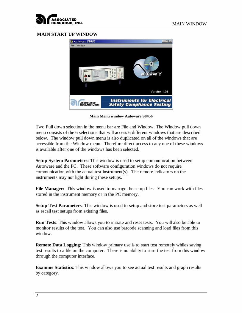
MAIN START UP WINDOW
Main Menu window Autoware S8456
Two Pull down selection in the menu bar are File and Window. The Window pull downmenu consists of the 6 selections that will access 6 different windows that are describedbelow. The window pull down menu is also duplicated on all of the windows that areaccessible from the Window menu. Therefore direct access to any one of these windowsis available after one of the windows has been selected.
Setup System Parameters: This window is used to setup communication betweenAutoware and the PC. These software configuration windows do not requirecommunication with the actual test instrument(s). The remote indicators on theinstruments may not light during these setups.
File Manager: This window is used to manage the setup files. You can work with filesstored in the instrument memory or in the PC memory.
Setup Test Parameters: This window is used to setup and store test parameters as wellas recall test setups from existing files.
Run Tests: This window allows you to initiate and reset tests. You will also be able tomonitor results of the test. You can also use barcode scanning and load files from thiswindow.
Remote Data Logging: This window primary use is to start test remotely whiles savingtest results to a file on the computer. There is no ability to start the test from this windowthrough the computer interface.
Examine Statistics: This window allows you to see actual test results and graph resultsby category.
SETUP SYSTEM PARAMETERS
3
SETUP SYSTEM PARAMETERSThis window will automatically be started when you first install the software. The firstoption on this window is titled "Instruments Configuration". This control allows you toselect which instruments you wish to control. The software defaults to configuration one.This control is used to select different combinations of instruments and system settings totailor your testing environment for different situations. You can scroll through theconfigurations by clicking on the up/down arrow and the display window will indicatewhich instruments are configured for that configuration number. You are allowed to haveup to 999 different configurations.
There are 10 tabs on this window that will take you to a different page of system settings.The tabs are labeled; Primary unit, 620L unit, Security, Bar Code, Auto File Loading,Calibration, Print, Demo, Remote Scanners, and Startup. There is also an Auto-Configuration button located by the Instrument Configuration menu. Please refer to thefollowing sections for descriptions of the parameters on each page.
Auto-ConfigurationThe Auto-Configuration feature allows Autoware to automatically scan the PC for activeserial, GPIB ports or Ethernet addresses. Using this button will allow Autoware to scanthe network for Associated Research, Inc. testers compatible with the Autoware S8456software.
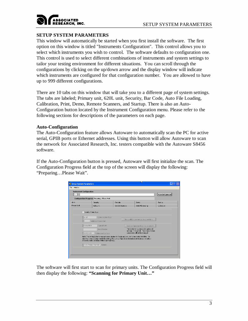
If the Auto-Configuration button is pressed, Autoware will first initialize the scan. TheConfiguration Progress field at the top of the screen will display the following:“Preparing… Please Wait”.
The software will first start to scan for primary units. The Configuration Progress field willthen display the following: “Scanning for Primary Unit… ”
SETUP SYSTEM PARAMETERS
4
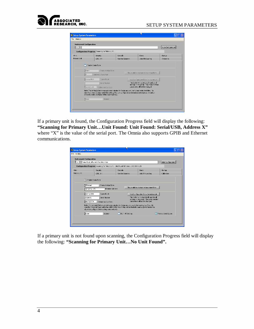
If a primary unit is found, the Configuration Progress field will display the following:“Scanning for Primary Unit… Unit Found: Unit Found: Serial/USB, Address X”where “X” is the value of the serial port. The Omnia also supports GPIB and Ethernetcommunications.
If a primary unit is not found upon scanning, the Configuration Progress field will displaythe following: “Scanning for Primary Unit… No Unit Found”.
SETUP SYSTEM PARAMETERS
5
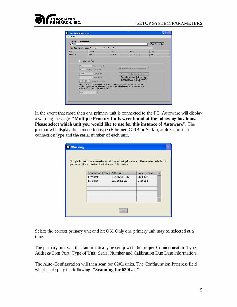
In the event that more than one primary unit is connected to the PC, Autoware will displaya warning message: “Multiple Primary Units were found at the following locations.Please select which unit you would like to use for this instance of Autoware”. Theprompt will display the connection type (Ethernet, GPIB or Serial), address for thatconnection type and the serial number of each unit.
Select the correct primary unit and hit OK. Only one primary unit may be selected at atime.
The primary unit will then automatically be setup with the proper Communication Type,Address/Com Port, Type of Unit, Serial Number and Calibration Due Date information.
The Auto-Configuration will then scan for 620L units. The Configuration Progress fieldwill then display the following: “Scanning for 620L… ”
SETUP SYSTEM PARAMETERS
6
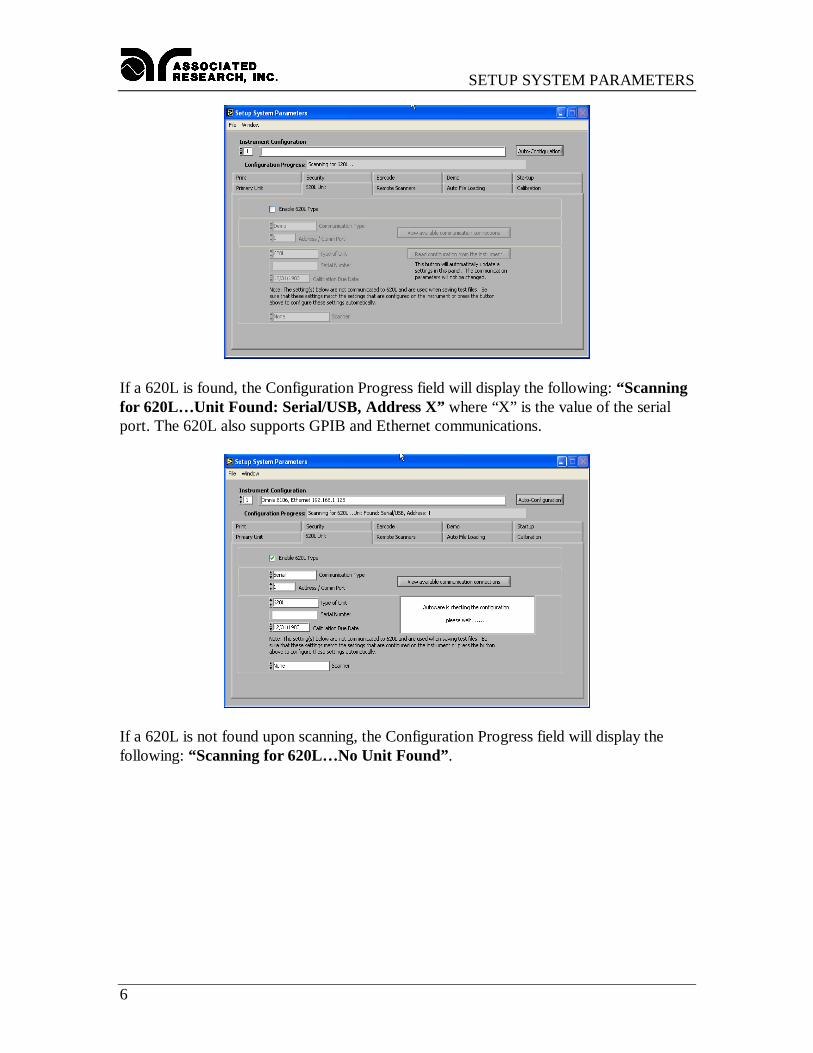
If a 620L is found, the Configuration Progress field will display the following: “Scanningfor 620L… Unit Found: Serial/USB, Address X” where “X” is the value of the serialport. The 620L also supports GPIB and Ethernet communications.
If a 620L is not found upon scanning, the Configuration Progress field will display thefollowing: “Scanning for 620L… No Unit Found”.
SETUP SYSTEM PARAMETERS
7
In the event that more than one 620L is connected to the PC, Autoware will display awarning message: “Multiple 620Ls were found at the following locations. Please selectwhich unit you would like to use for this instance of Autoware”. The prompt willdisplay the connection type (Ethernet, GPIB or Serial), address for that connection typeand the serial number of each unit. Select the correct 620L and hit OK. Only one 620Lmay be selected at a time.
The 620L will then automatically be setup with the proper Communication Type,Address/Com Port, Type of Unit, Serial Number and Calibration Due Date information.
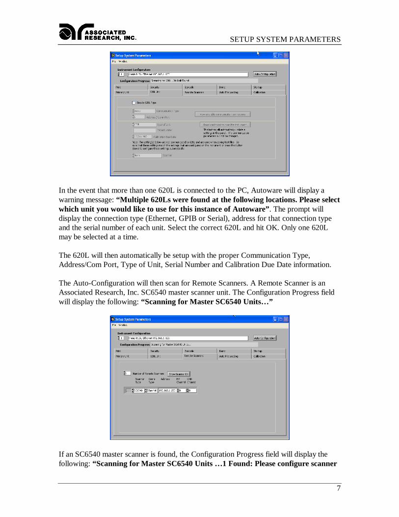
The Auto-Configuration will then scan for Remote Scanners. A Remote Scanner is anAssociated Research, Inc. SC6540 master scanner unit. The Configuration Progress fieldwill display the following: “Scanning for Master SC6540 Units… ”
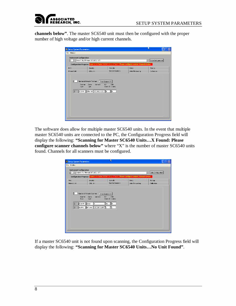
If an SC6540 master scanner is found, the Configuration Progress field will display thefollowing: “Scanning for Master SC6540 Units … 1 Found: Please configure scanner
SETUP SYSTEM PARAMETERS
8
channels below”. The master SC6540 unit must then be configured with the propernumber of high voltage and/or high current channels.
The software does allow for multiple master SC6540 units. In the event that multiplemaster SC6540 units are connected to the PC, the Configuration Progress field willdisplay the following: “Scanning for Master SC6540 Units… X Found: Pleaseconfigure scanner channels below” where “X” is the number of master SC6540 unitsfound. Channels for all scanners must be configured.
If a master SC6540 unit is not found upon scanning, the Configuration Progress field willdisplay the following: “Scanning for Master SC6540 Units… No Unit Found”.
SETUP SYSTEM PARAMETERS
9
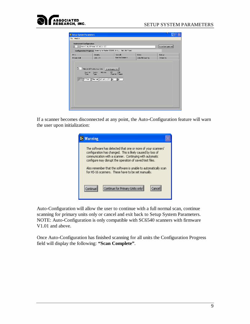
If a scanner becomes disconnected at any point, the Auto-Configuration feature will warnthe user upon initialization:
Auto-Configuration will allow the user to continue with a full normal scan, continuescanning for primary units only or cancel and exit back to Setup System Parameters.NOTE: Auto-Configuration is only compatible with SC6540 scanners with firmwareV1.01 and above.
Once Auto-Configuration has finished scanning for all units the Configuration Progressfield will display the following: “Scan Complete”.
SETUP SYSTEM PARAMETERS
10
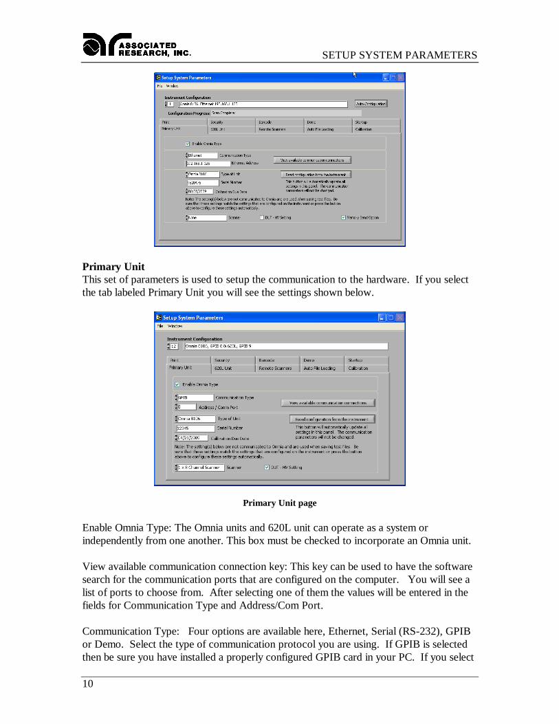
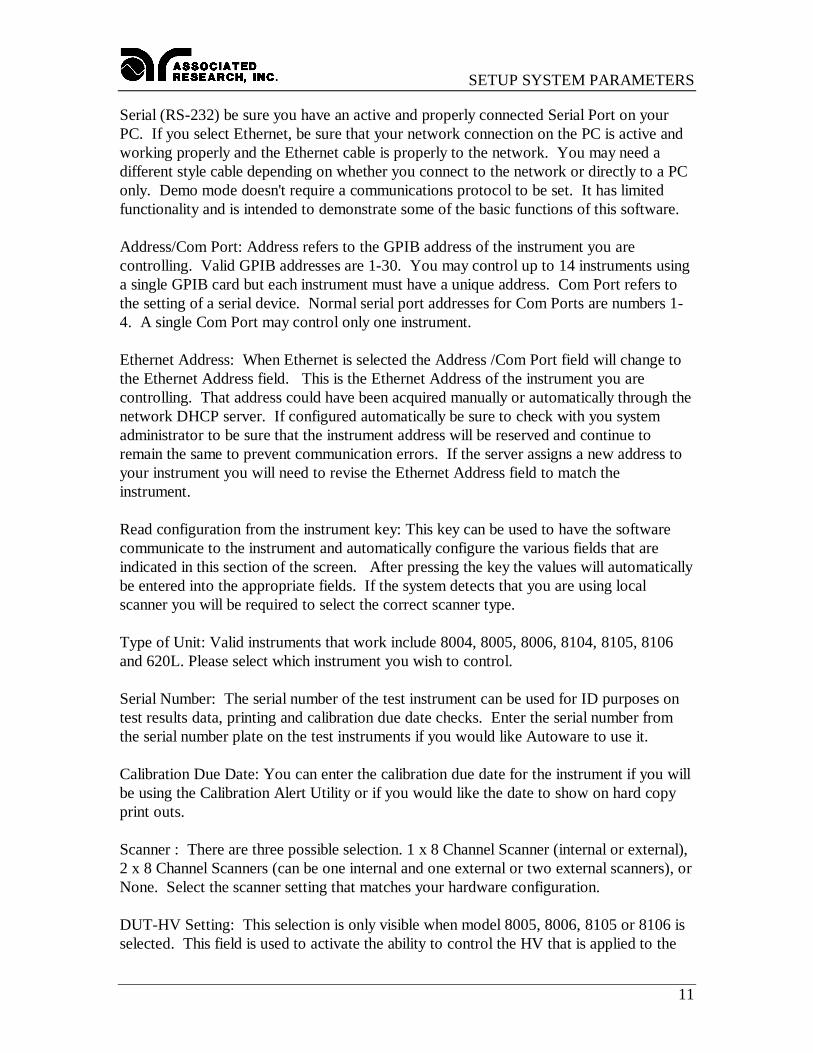
Primary UnitThis set of parameters is used to setup the communication to the hardware. If you selectthe tab labeled Primary Unit you will see the settings shown below.
Primary Unit page
Enable Omnia Type: The Omnia units and 620L unit can operate as a system orindependently from one another. This box must be checked to incorporate an Omnia unit.
View available communication connection key: This key can be used to have the softwaresearch for the communication ports that are configured on the computer. You will see alist of ports to choose from. After selecting one of them the values will be entered in thefields for Communication Type and Address/Com Port.
Communication Type: Four options are available here, Ethernet, Serial (RS-232), GPIBor Demo. Select the type of communication protocol you are using. If GPIB is selectedthen be sure you have installed a properly configured GPIB card in your PC. If you select
SETUP SYSTEM PARAMETERS
11
Serial (RS-232) be sure you have an active and properly connected Serial Port on yourPC. If you select Ethernet, be sure that your network connection on the PC is active andworking properly and the Ethernet cable is properly to the network. You may need adifferent style cable depending on whether you connect to the network or directly to a PConly. Demo mode doesn't require a communications protocol to be set. It has limitedfunctionality and is intended to demonstrate some of the basic functions of this software.
Address/Com Port: Address refers to the GPIB address of the instrument you arecontrolling. Valid GPIB addresses are 1-30. You may control up to 14 instruments usinga single GPIB card but each instrument must have a unique address. Com Port refers tothe setting of a serial device. Normal serial port addresses for Com Ports are numbers 1-4. A single Com Port may control only one instrument.
Ethernet Address: When Ethernet is selected the Address /Com Port field will change tothe Ethernet Address field. This is the Ethernet Address of the instrument you arecontrolling. That address could have been acquired manually or automatically through thenetwork DHCP server. If configured automatically be sure to check with you systemadministrator to be sure that the instrument address will be reserved and continue toremain the same to prevent communication errors. If the server assigns a new address toyour instrument you will need to revise the Ethernet Address field to match theinstrument.
Read configuration from the instrument key: This key can be used to have the softwarecommunicate to the instrument and automatically configure the various fields that areindicated in this section of the screen. After pressing the key the values will automaticallybe entered into the appropriate fields. If the system detects that you are using localscanner you will be required to select the correct scanner type.
Type of Unit: Valid instruments that work include 8004, 8005, 8006, 8104, 8105, 8106and 620L. Please select which instrument you wish to control.
Serial Number: The serial number of the test instrument can be used for ID purposes ontest results data, printing and calibration due date checks. Enter the serial number fromthe serial number plate on the test instruments if you would like Autoware to use it.
Calibration Due Date: You can enter the calibration due date for the instrument if you willbe using the Calibration Alert Utility or if you would like the date to show on hard copyprint outs.
Scanner : There are three possible selection. 1 x 8 Channel Scanner (internal or external),2 x 8 Channel Scanners (can be one internal and one external or two external scanners), orNone. Select the scanner setting that matches your hardware configuration.
DUT-HV Setting: This selection is only visible when model 8005, 8006, 8105 or 8106 isselected. This field is used to activate the ability to control the HV that is applied to the

SETUP SYSTEM PARAMETERS
12
Line and Neutral connectors of the DUT Outputs on model 8005, 8006, 8105 or 8106.When this field is checked the HV Output selection on the Setup Test Parameters windowwill be enabled for HV test types ACW, DCW, and IR. When it is left unchecked the HVOutput selection will not be visible on the Setup Test window. NOTE: This selectionwill not change the System Setting in the Hardware menu on the Omnia hardware. If thisfunction is required be sure that the hardware is configured to match the selection in thiswindow. If the selection does not match the hardware then errors will occur when savingfiles to Omnia.
620L UnitThis set of parameters is used to setup the communication to the hardware. If you selectthe tab labeled 620L unit you will see the settings shown below.
620L Unit page
Enable 620L Type: If you are using a system, this box must be checked to control a 620Lunit. The Omnia units and 620L unit can operate as a system or independently from oneanother.
The 620L unit tab has the same parameters as the primary unit tab. The device control isset through available communication connections, Communication Type, Address/commport, Ethernet address, Read configuration from instrument key, Type of unit (620L unit isthe only option), Serial Number, Calibration due date and scanner control. NOTE: The620L unit does not have the capability to enable the DUT-HV setting.
CalibrationThe calibration due date for the test instruments can be checked each time that thesoftware is started. The "# of days to warn" field is used to select the number of daysprior to calibration due date that the software will prompt you that the instrument is duefor calibration. The calibration warning message can only be cleared by a user that has
SETUP SYSTEM PARAMETERS
13
Full System Access security rights, so that management personnel will be aware of thecalibration due information.
The prompt will only be shown one time until the calibration is out of date. When thecalibration date is equal to or past the due date the prompt will occur after the software isstarted and one of the operation windows begins to load. The warning is always relativeto the instruments under control configuration that has been selected in Setup SystemParameters.
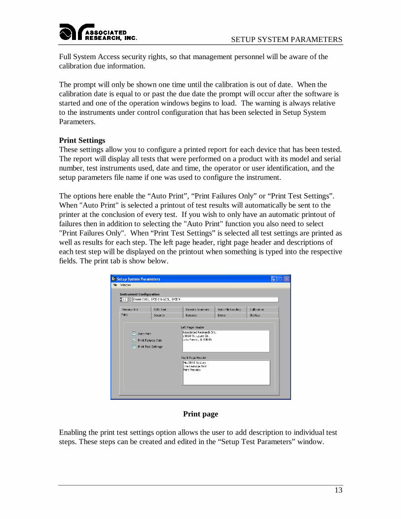
Print SettingsThese settings allow you to configure a printed report for each device that has been tested.The report will display all tests that were performed on a product with its model and serialnumber, test instruments used, date and time, the operator or user identification, and thesetup parameters file name if one was used to configure the instrument.
The options here enable the “Auto Print”, “Print Failures Only” or “Print Test Settings”.When "Auto Print" is selected a printout of test results will automatically be sent to theprinter at the conclusion of every test. If you wish to only have an automatic printout offailures then in addition to selecting the "Auto Print" function you also need to select"Print Failures Only". When “Print Test Settings” is selected all test settings are printed aswell as results for each step. The left page header, right page header and descriptions ofeach test step will be displayed on the printout when something is typed into the respectivefields. The print tab is show below.
Print page
Enabling the print test settings option allows the user to add description to individual teststeps. These steps can be created and edited in the “Setup Test Parameters” window.
SETUP SYSTEM PARAMETERS
14
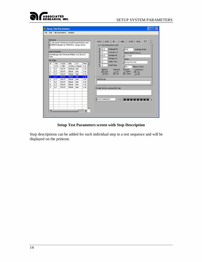
Setup Test Parameters screen with Step Description
Step descriptions can be added for each individual step in a test sequence and will bedisplayed on the printout.
SETUP SYSTEM PARAMETERS
15
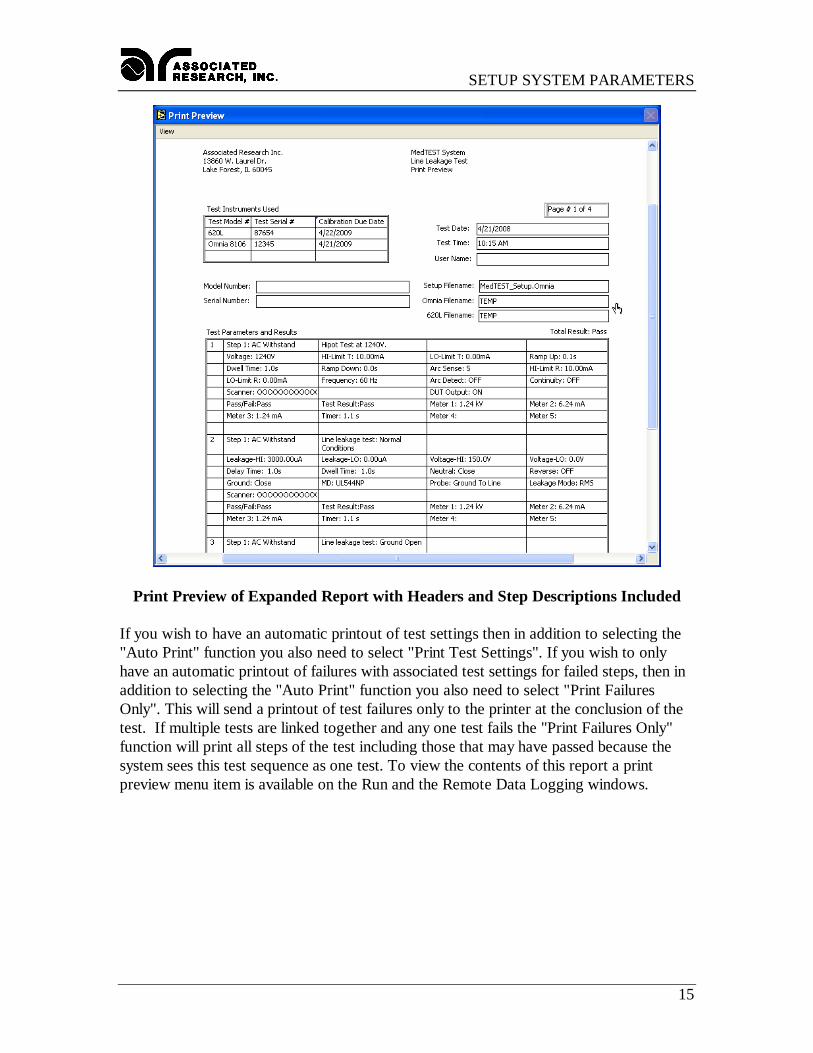
Print Preview of Expanded Report with Headers and Step Descriptions Included
If you wish to have an automatic printout of test settings then in addition to selecting the"Auto Print" function you also need to select "Print Test Settings". If you wish to onlyhave an automatic printout of failures with associated test settings for failed steps, then inaddition to selecting the "Auto Print" function you also need to select "Print FailuresOnly". This will send a printout of test failures only to the printer at the conclusion of thetest. If multiple tests are linked together and any one test fails the "Print Failures Only"function will print all steps of the test including those that may have passed because thesystem sees this test sequence as one test. To view the contents of this report a printpreview menu item is available on the Run and the Remote Data Logging windows.
SETUP SYSTEM PARAMETERS
16
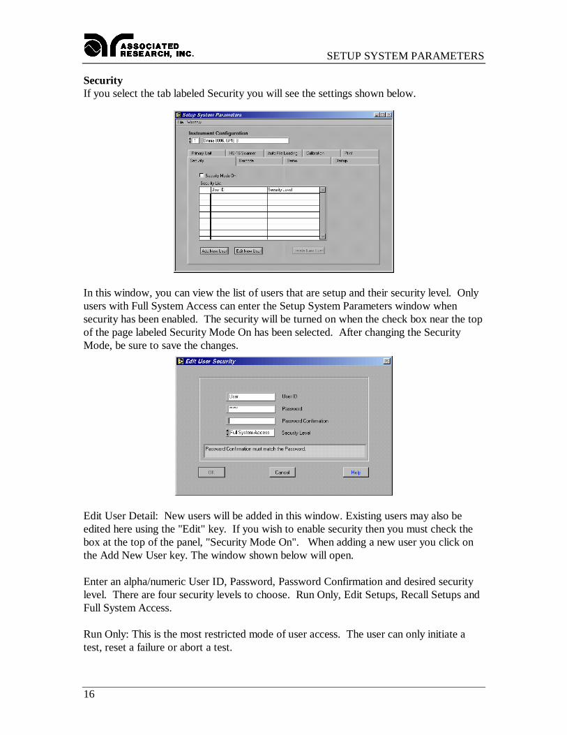
SecurityIf you select the tab labeled Security you will see the settings shown below.
In this window, you can view the list of users that are setup and their security level. Onlyusers with Full System Access can enter the Setup System Parameters window whensecurity has been enabled. The security will be turned on when the check box near the topof the page labeled Security Mode On has been selected. After changing the SecurityMode, be sure to save the changes.
Edit User Detail: New users will be added in this window. Existing users may also beedited here using the "Edit" key. If you wish to enable security then you must check thebox at the top of the panel, "Security Mode On". When adding a new user you click onthe Add New User key. The window shown below will open.
Enter an alpha/numeric User ID, Password, Password Confirmation and desired securitylevel. There are four security levels to choose. Run Only, Edit Setups, Recall Setups andFull System Access.
Run Only: This is the most restricted mode of user access. The user can only initiate atest, reset a failure or abort a test.
SETUP SYSTEM PARAMETERS
17
Recall Setups: This mode allows the user to recall previously configured test setups but itdoes not allow any editing of the parameters. In this mode the user is restricted fromaccess to the "Setup Test Parameters" window.
Edit Setups: In this mode the user can recall and edit test parameters.
Full System Access: In this mode the user has full access level to all instrument setupparameters as well as software configuration and security levels. Access at this levelshould be restricted to System Administrators.
SETUP SYSTEM PARAMETERS
18
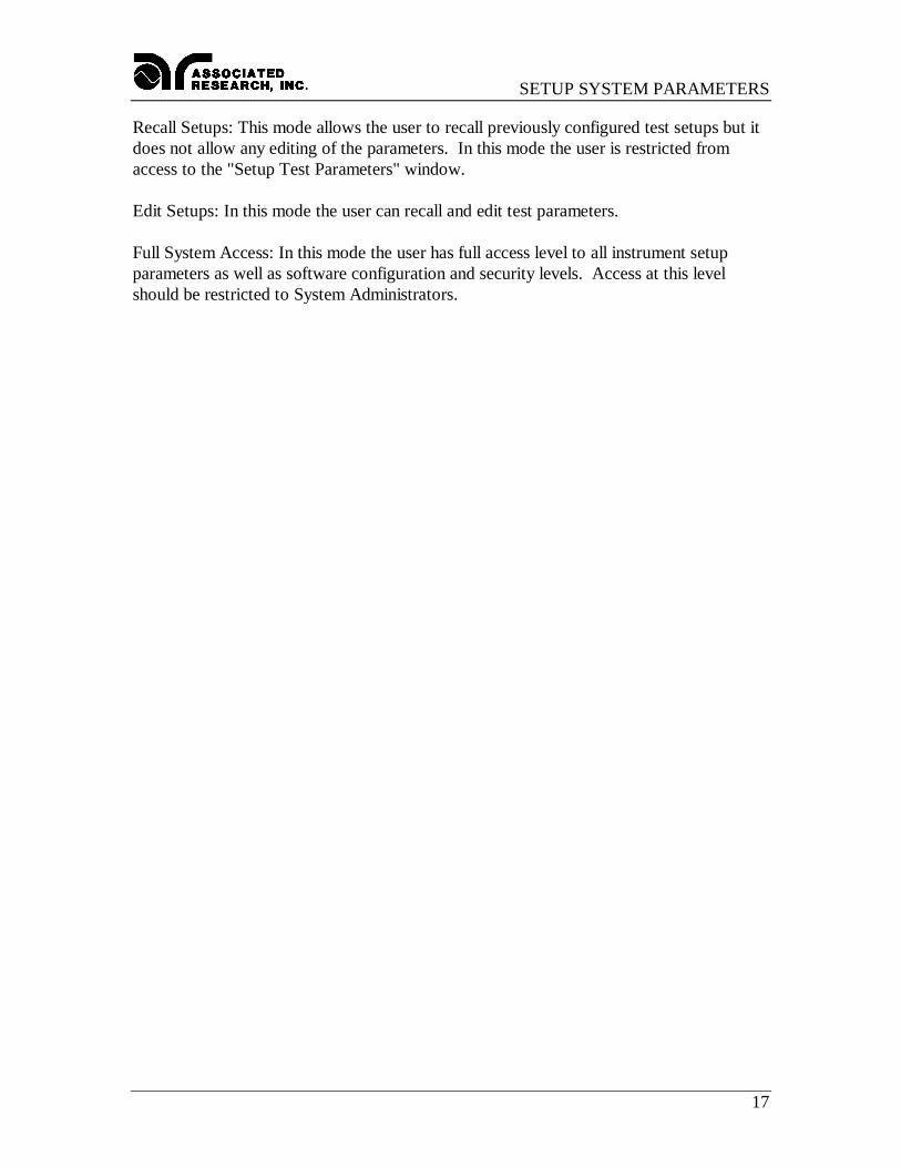
Auto Load ParametersIf you select the Tab labeled “Auto File Loading” you will see the settings shown below.
These settings allow the operator to automatically load and edit setup files by associatingthe test parameter setup files to a model number. You must have already created the setupfile using the Setup Test Parameters windows before you can make the association. Whena model number is typed or scanned with a bar code scanner then the setup file would beautomatically loaded if it were not already loaded.
This window shows a list of all associations and allows access to a sub-level windows tomake changes to the association. The association feature can be enabled or disabled byselecting the check box at the top of the page. The check box must be enabled for theauto loading to occur on the Run or the Remote Data Logging windows.
Another feature of Auto File Loading is the ability to require a valid model number toenable the Test button. This assures that tests will only be performed on models that havevalid test programs loaded to the RUN window before tests can be performed. If themodel entered on the RUN test window does not have a valid association to a setup filethen a pop-up warning message will appear if the Test button is pressed. To enable thisfeature check the "Configuration Required to Execute Test" box. This field does not haveany effect in the Remote Data Logging window since the tests are started remotely andAutoware does not control the starting of tests in that window.
Use the Export to File button to export the list of associated model number and setup filenames to a file. The file created is a standard ASCII file with TAB delimited columns.This file can be used to print or edit the information from spreadsheet or word processingprograms such as Microsoft Excel or Word.
SETUP SYSTEM PARAMETERS
19
You can create a new model association or click on the delete key to cancel an associationafter you have highlighted the appropriate selection. To change an association for specificmodel you must first delete the association and then create a new one by adding a newmodel.
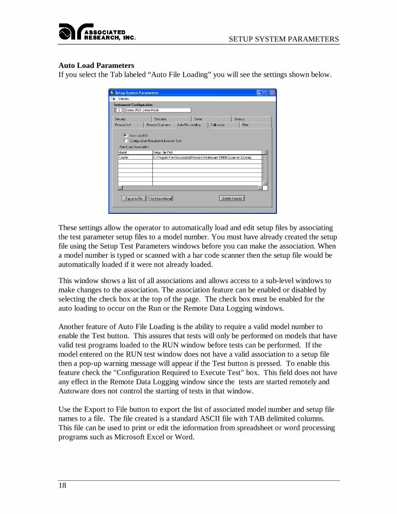
Add New Model button: Clicking on this button will launch the window shown below.
First type in the model number then click on "Specify Setup File Path" key. A pop upwindow will appear to select the file. Select the file then click the OK key on the popupwindow. Verify that the correct path is shown in the path window then click the OK keyto complete the association.
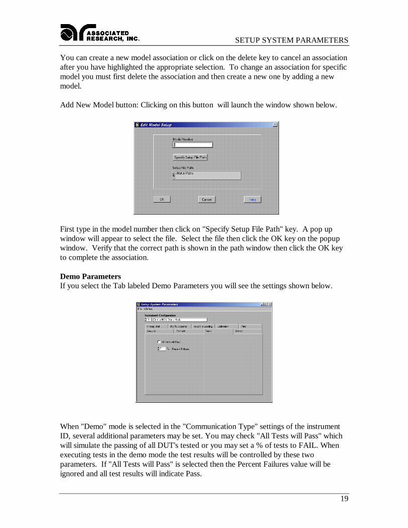
Demo ParametersIf you select the Tab labeled Demo Parameters you will see the settings shown below.
When "Demo" mode is selected in the "Communication Type" settings of the instrumentID, several additional parameters may be set. You may check "All Tests will Pass" whichwill simulate the passing of all DUT's tested or you may set a % of tests to FAIL. Whenexecuting tests in the demo mode the test results will be controlled by these twoparameters. If "All Tests will Pass" is selected then the Percent Failures value will beignored and all test results will indicate Pass.
SETUP SYSTEM PARAMETERS
20
When "All Tests will Pass" is not selected then the program uses the Percent Failure valueto generate an approximate failure rate based on this number. For example; if the percentfailure value is 20%, 2 out of 10 tests will generate a failure result.
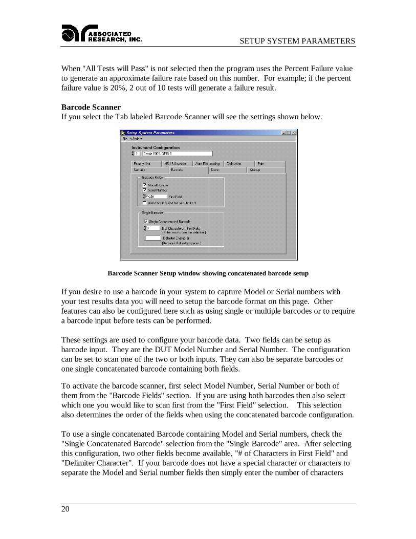
Barcode ScannerIf you select the Tab labeled Barcode Scanner will see the settings shown below.
Barcode Scanner Setup window showing concatenated barcode setup
If you desire to use a barcode in your system to capture Model or Serial numbers withyour test results data you will need to setup the barcode format on this page. Otherfeatures can also be configured here such as using single or multiple barcodes or to requirea barcode input before tests can be performed.
These settings are used to configure your barcode data. Two fields can be setup asbarcode input. They are the DUT Model Number and Serial Number. The configurationcan be set to scan one of the two or both inputs. They can also be separate barcodes orone single concatenated barcode containing both fields.
To activate the barcode scanner, first select Model Number, Serial Number or both ofthem from the "Barcode Fields" section. If you are using both barcodes then also selectwhich one you would like to scan first from the "First Field" selection. This selectionalso determines the order of the fields when using the concatenated barcode configuration.
To use a single concatenated Barcode containing Model and Serial numbers, check the"Single Concatenated Barcode" selection from the "Single Barcode" area. After selectingthis configuration, two other fields become available, "# of Characters in First Field" and"Delimiter Character". If your barcode does not have a special character or characters toseparate the Model and Serial number fields then simply enter the number of characters
SETUP SYSTEM PARAMETERS
21
that represents your first field. The remaining characters in the barcode will be used forthe second field.
If your barcode uses a character separator or delimiter then set the "# of Characters inFirst Field" equal to "0" and enter the delimiter character in the "Delimiter Character"field. The first field will use all of the characters before the delimiter character and thesecond field will use all characters after the delimiter.
Another feature of the barcode configuration is the ability to require a barcode data inputto enable the Test button. This assures that the Model and/or Serial numbers will berecorded along with the test results for printing or data storage functions. To enable thisfeature check the "Barcode Required to Execute Test" selection in the "Barcode Fields"area. This field does not have any effect in the Remote Data Logging window since thetests are started remotely and Autoware does not control the starting of tests in thatwindow.
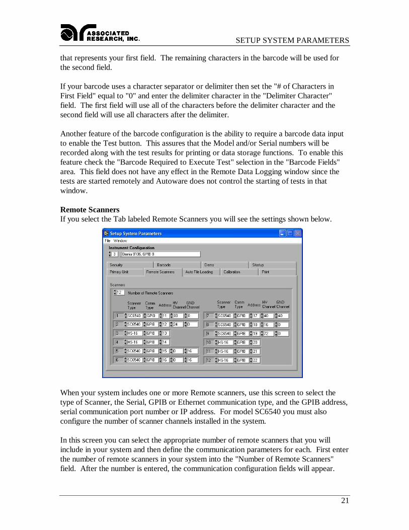
Remote ScannersIf you select the Tab labeled Remote Scanners you will see the settings shown below.
When your system includes one or more Remote scanners, use this screen to select thetype of Scanner, the Serial, GPIB or Ethernet communication type, and the GPIB address,serial communication port number or IP address. For model SC6540 you must alsoconfigure the number of scanner channels installed in the system.
In this screen you can select the appropriate number of remote scanners that you willinclude in your system and then define the communication parameters for each. First enterthe number of remote scanners in your system into the "Number of Remote Scanners"field. After the number is entered, the communication configuration fields will appear.
SETUP SYSTEM PARAMETERS
22
First select either SC6540 or HS-16 model numbers under the scanner type field for eachadditional remote scanner. Then select one of the three communication types, GPIB,Serial, Ethernet or Demo mode. In Demo mode you will be able to run the softwarewithout having any instrument connected to the system. Next, enter a valid number in theAddress / Comm Port field for the appropriate communications type that you haveselected.
If the scanner has Ethernet communication protocol, the “Show Scanner ID” button canbe used to display the scanner’s dip switch configuration. This makes it easier to keeptrack of various scanners on a network.
If you have scanner model SC6540 configured in the system then also enter the number ofHV and/or GND channels that will be controlled from that communication port, and thenclick OK to save the configuration. The scanner configuration will be saved within thesystem setup file along with communication parameters for the other test instruments inthe system.
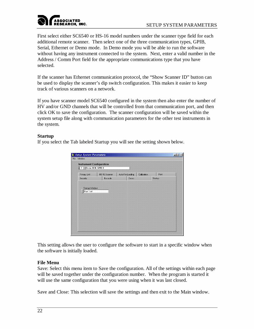
StartupIf you select the Tab labeled Startup you will see the setting shown below.
This setting allows the user to configure the software to start in a specific window whenthe software is initially loaded.
File MenuSave: Select this menu item to Save the configuration. All of the settings within each pagewill be saved together under the configuration number. When the program is started itwill use the same configuration that you were using when it was last closed.
Save and Close: This selection will save the settings and then exit to the Main window.

SETUP SYSTEM PARAMETERS
23
Auto-Configuration: This selection will initiate the Auto-Configuration feature and willscan for any units connected to the PC. See the Auto-Configuration description at thebeginning of this section for details.
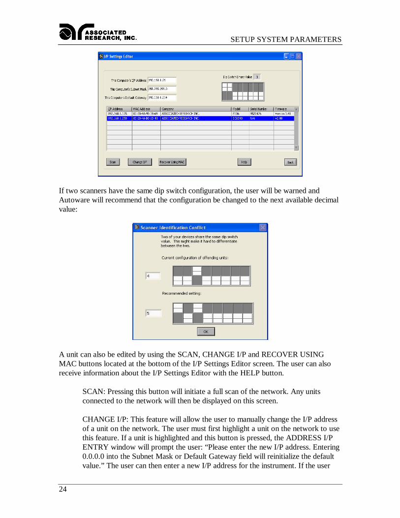
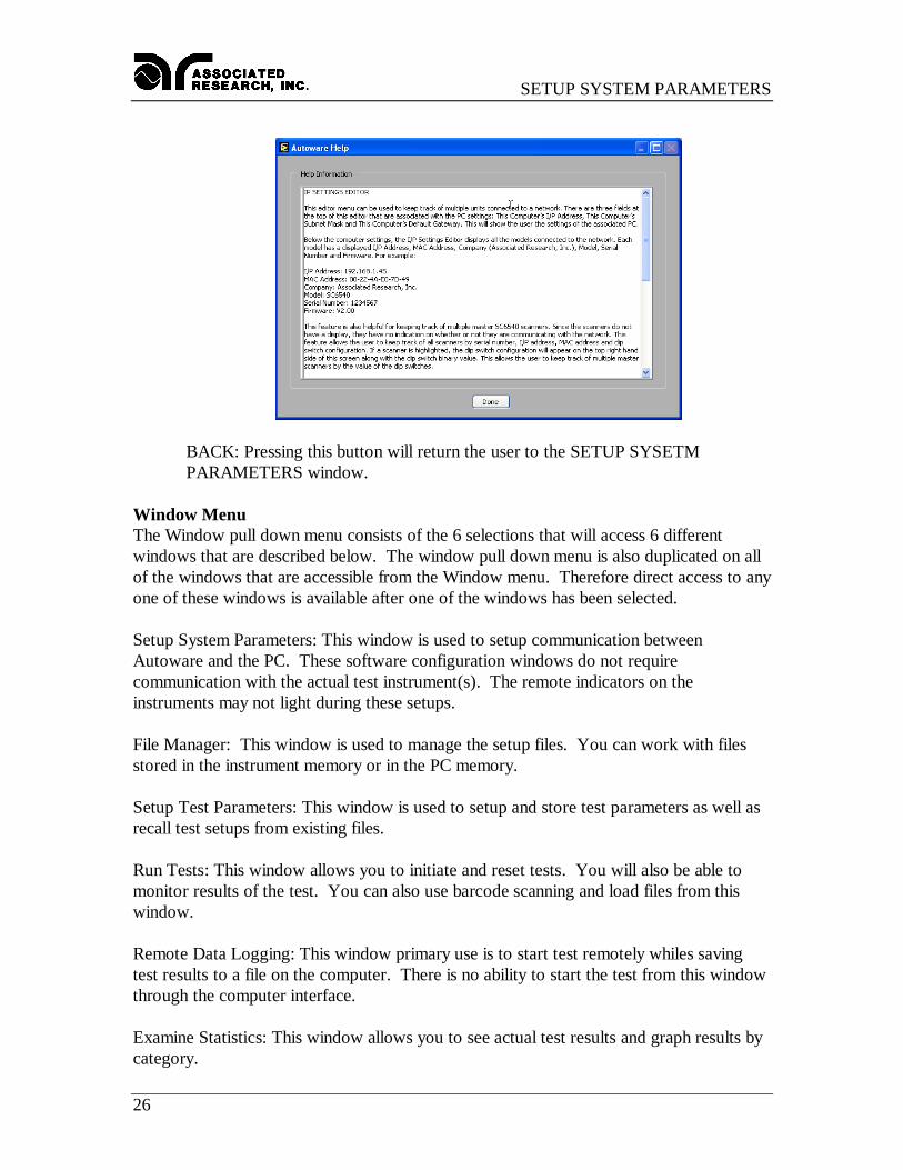
I/P Settings Editor: This editor menu can be used to keep track of multiple unitsconnected to a network. There are three fields at the top of this editor that are associatedwith the PC settings: This Computer’s I/P Address, This Computer’s Subnet Mask andThis Computer’s Default Gateway. This will show the user the settings of the associatedPC. The image below illustrates the I/P Settings Editor window:
Below the computer settings, the I/P Settings Editor displays all the models connected tothe network. Each model has a displayed I/P Address, MAC Address, Company(Associated Research, Inc.), Model, Serial Number and Firmware. For example:
I/P Address: 192.168.1.45MAC Address: 00-22-4A-E0-7D-49Company: Associated Research, Inc.Model: SC6540Serial Number: 1234567Firmware: V2.00
This feature is also helpful for keeping track of multiple master SC6540 scanners. Sincethe scanners do not have a display, they have no indication on whether or not they arecommunicating with the network. This feature allows the user to keep track of all scannersby serial number, I/P address, MAC address and dip switch configuration. If a scanner ishighlighted, the dip switch configuration will appear on the top right hand side of thisscreen along with the dip switch binary value. This allows the user to keep track ofmultiple master scanners by the value of the dip switches.
SETUP SYSTEM PARAMETERS
24
If two scanners have the same dip switch configuration, the user will be warned andAutoware will recommend that the configuration be changed to the next available decimalvalue:
A unit can also be edited by using the SCAN, CHANGE I/P and RECOVER USINGMAC buttons located at the bottom of the I/P Settings Editor screen. The user can alsoreceive information about the I/P Settings Editor with the HELP button.
SCAN: Pressing this button will initiate a full scan of the network. Any unitsconnected to the network will then be displayed on this screen.
CHANGE I/P: This feature will allow the user to manually change the I/P addressof a unit on the network. The user must first highlight a unit on the network to usethis feature. If a unit is highlighted and this button is pressed, the ADDRESS I/PENTRY window will prompt the user: “Please enter the new I/P address. Entering0.0.0.0 into the Subnet Mask or Default Gateway field will reinitialize the defaultvalue.” The user can then enter a new I/P address for the instrument. If the user
SETUP SYSTEM PARAMETERS
25
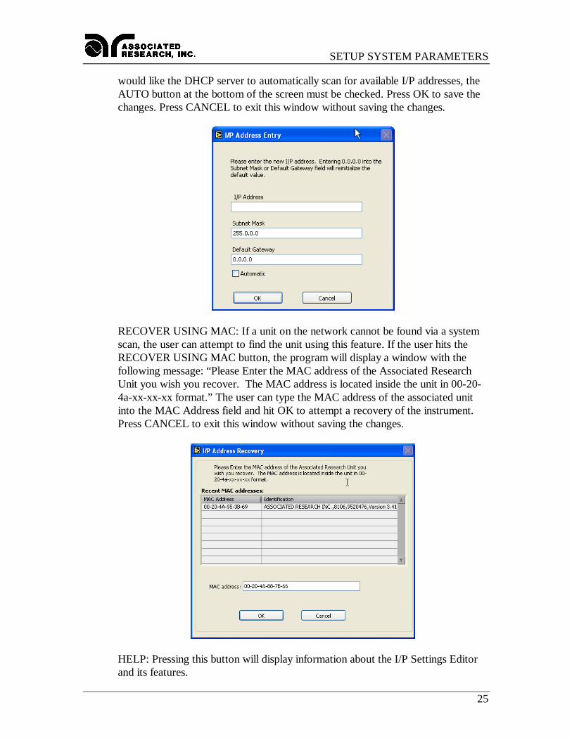
would like the DHCP server to automatically scan for available I/P addresses, theAUTO button at the bottom of the screen must be checked. Press OK to save thechanges. Press CANCEL to exit this window without saving the changes.
RECOVER USING MAC: If a unit on the network cannot be found via a systemscan, the user can attempt to find the unit using this feature. If the user hits theRECOVER USING MAC button, the program will display a window with thefollowing message: “Please Enter the MAC address of the Associated ResearchUnit you wish you recover. The MAC address is located inside the unit in 00-20-4a-xx-xx-xx format.” The user can type the MAC address of the associated unitinto the MAC Address field and hit OK to attempt a recovery of the instrument.Press CANCEL to exit this window without saving the changes.
HELP: Pressing this button will display information about the I/P Settings Editorand its features.
SETUP SYSTEM PARAMETERS
26
BACK: Pressing this button will return the user to the SETUP SYSETMPARAMETERS window.
Window MenuThe Window pull down menu consists of the 6 selections that will access 6 differentwindows that are described below. The window pull down menu is also duplicated on allof the windows that are accessible from the Window menu. Therefore direct access to anyone of these windows is available after one of the windows has been selected.
Setup System Parameters: This window is used to setup communication betweenAutoware and the PC. These software configuration windows do not requirecommunication with the actual test instrument(s). The remote indicators on theinstruments may not light during these setups.
File Manager: This window is used to manage the setup files. You can work with filesstored in the instrument memory or in the PC memory.
Setup Test Parameters: This window is used to setup and store test parameters as well asrecall test setups from existing files.
Run Tests: This window allows you to initiate and reset tests. You will also be able tomonitor results of the test. You can also use barcode scanning and load files from thiswindow.
Remote Data Logging: This window primary use is to start test remotely whiles savingtest results to a file on the computer. There is no ability to start the test from this windowthrough the computer interface.
Examine Statistics: This window allows you to see actual test results and graph results bycategory.
FILE MANAGER
27
FILE MANAGERThe File manager window serves two functions
1. View and organize existing files in Omnia and in the computers memory.2. Perform batch execution to configure Omnia’s memory.
The file menu is divided into two main sections. The left side is used to manage the filesand the right half is used to configure a batch process. When Enable Batch Processing isnot selected in the menu, the Omnia Batch table will be disabled and grayed out.
The menu selections for file managing are Save As, Rename, Delete. To use these menuselection first select the file you want to work with from the Files list and then select themenu item from the File menu.
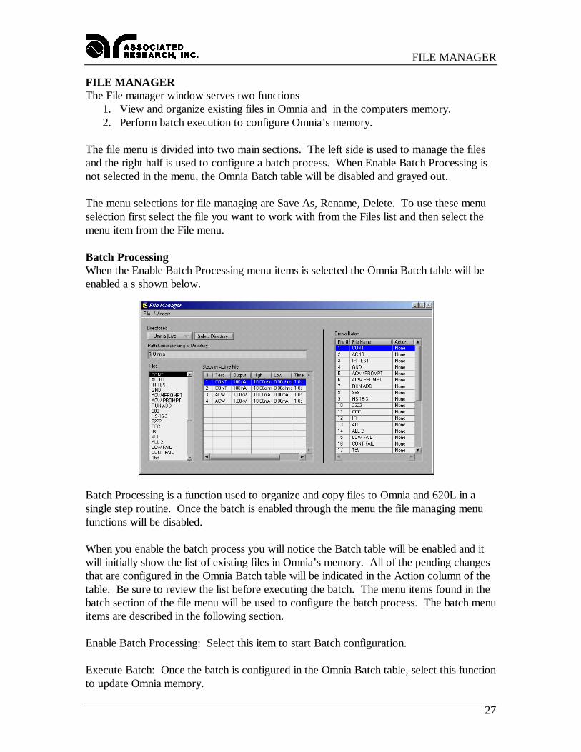
Batch ProcessingWhen the Enable Batch Processing menu items is selected the Omnia Batch table will beenabled a s shown below.
Batch Processing is a function used to organize and copy files to Omnia and 620L in asingle step routine. Once the batch is enabled through the menu the file managing menufunctions will be disabled.
When you enable the batch process you will notice the Batch table will be enabled and itwill initially show the list of existing files in Omnia’s memory. All of the pending changesthat are configured in the Omnia Batch table will be indicated in the Action column of thetable. Be sure to review the list before executing the batch. The menu items found in thebatch section of the file menu will be used to configure the batch process. The batch menuitems are described in the following section.
Enable Batch Processing: Select this item to start Batch configuration.
Execute Batch: Once the batch is configured in the Omnia Batch table, select this functionto update Omnia memory.
FILE MANAGER
28
Replace Omnia File: This function will delete the file selected in the Omnia Batch tableand replace it with the file selected on the File list. A window will open that will alsoallow you to change the name if desired or you can keep the original name. The action forthis file will indicate Replace.
Insert to Omnia: This function is used to insert the file selected on the File list into theOmnia Batch table. The new file will be inserted at the location that is highlighted in theOmnia Batch table. The file already at this location and all files below it will move downone position. The action for this file will indicate Insert.
Delete from Batch: Use the Delete function to delete files from Omnia’s memory. Selectthe files on the Omnia Batch table on the right side of the window and select Delete fromBatch from the batch section of the File menu. The action for this file will indicate Delete.
Rename: This function will leave the file parameters unchanged but give the file a newname. Select the files on the Omnia Batch table on the right side of the window thenselect Rename from the File menu. A dialog window will open to allow you to type in thenew name. The new name will be shown in the Omnia Batch table and the action for thisfile will indicate Rename.
Once the batch configuration is setup then Select Execute Batch from the menu to send allfiles to Omnia. The File list on left side should update with all the new files that areconfigured in Omnia’s memory when Omnia (live) is selected from the directory list.
Window MenuThe Window pull down menu consists of the 6 selections that will access 6 differentwindows that are described below. The window pull down menu is also duplicated on allof the windows that are accessible from the Window menu. Therefore direct access to anyone of these windows is available after one of the windows has been selected.
Setup System Parameters: This window is used to setup communication betweenAutoware and the PC. These software configuration windows do not requirecommunication with the actual test instrument(s). The remote indicators on theinstruments may not light during these setups.
File Manager: This window is used to manage the setup files. You can work with filesstored in the instrument memory or in the PC memory.
Setup Test Parameters: This window is used to setup and store test parameters as well asrecall test setups from existing files.
Run Tests: This window allows you to initiate and reset tests. You will also be able tomonitor results of the test. You can also use barcode scanning and load files from thiswindow.

FILE MANAGER
29
Remote Data Logging: This window primary use is to start test remotely whiles savingtest results to a file on the computer. There is no ability to start the test from this windowthrough the computer interface.
Examine Statistics: This window allows you to see actual test results and graph results bycategory.
SETUP TEST PARAMETERS
30
SETUP TEST PARAMETERS
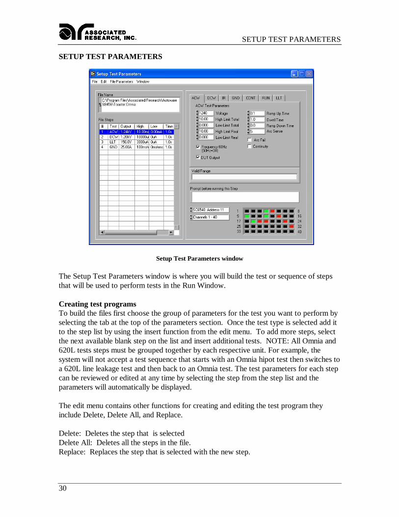
Setup Test Parameters window
The Setup Test Parameters window is where you will build the test or sequence of stepsthat will be used to perform tests in the Run Window.
Creating test programsTo build the files first choose the group of parameters for the test you want to perform byselecting the tab at the top of the parameters section. Once the test type is selected add itto the step list by using the insert function from the edit menu. To add more steps, selectthe next available blank step on the list and insert additional tests. NOTE: All Omnia and620L tests steps must be grouped together by each respective unit. For example, thesystem will not accept a test sequence that starts with an Omnia hipot test then switches toa 620L line leakage test and then back to an Omnia test. The test parameters for each stepcan be reviewed or edited at any time by selecting the step from the step list and theparameters will automatically be displayed.
The edit menu contains other functions for creating and editing the test program theyinclude Delete, Delete All, and Replace.
Delete: Deletes the step that is selectedDelete All: Deletes all the steps in the file.Replace: Replaces the step that is selected with the new step.

SETUP TEST PARAMETERS
31
Additional parameters that are associated with the entire test file (as apposed to each step)are located in the File Parameters menu. The Data file should be selected if you desire tostore these results in a data file on the computer. Once you have selected this option youwill be prompted for the data file name which can be created or an existing one can beselected. Also confirm that the Fail Stop Selection is correct. See the section on the FileParameters menu for more detail.
File creation Example:On Omnia model 8004 or 8104 there are five different types of tests you can perform: ACWithstand (ACW), DC Withstand (DCW), Insulation Resistance (IR), Ground Bond(GND) and Continuity (CONT). For our example we will run a Ground Bond test first,then an AC Withstand test and finally an IR test. We want to run these three tests insequence and automatically.
1). Be sure that the first step on the list is highlighted. Using the mouse, click on GroundBond (GND) tab. This will bring up the "GND Test Parameters" page.
2). Set your parameters for the Ground Bond Test on the right hand side of the window.Go to the Edit menu and select Insert . You should see a summary of the test at stepnumber 1.
3). Highlight step number 2 in the step list. Now click AC Withstand (ACW) tab withyour mouse. Go to the Edit menu and select Insert . You should see a summary of thetest at step number 2.
4). Repeat the same sequence of steps for the IR test for step number 3.
5). You can review each step’s parameters now by clicking the desired step on the steplist. Edit the parameters as desired for each step.
6). When all the changes are correct then save the file by selecting Save from the filemenu. You can either save the file directly to Omnia or save it to the PC to be later sentto Omnia when testing will be done.
File creation Example #2:On 620L model there are two different types of tests you can perform: Line Leakage(LLT) and Functional Run (Optional). However, the Omnia series can be used in tandemwith the 620L unit. For our example we will run a series of line leakage tests from the620L and two ACW tests from the Omnia 8104. We want to run these tests in sequenceand automatically.
1). Be sure that the first step on the list is highlighted. Using the mouse, click on ACWithstand (ACW) tab. This will bring up the "ACW Test Parameters" page.

SETUP TEST PARAMETERS
32
2). Set your parameters for the AC Withstand Test on the right hand side of the window.Go to the Edit menu and select Insert. You should see a summary of the test at stepnumber 1. Repeat number 1 and 2 for the next ACW test.
3). Highlight step number 3 in the step list. Now click Line Leakage (LLT) tab with yourmouse. Go to the Edit menu and select Insert . You should see a summary of the test atstep number 2.
4). Repeat the same sequence for the remaining line leakage tests as in step 3.
5). You can review each step’s parameters now by clicking the desired step on the steplist. Edit the parameters as desired for each step.
6). When all the changes are correct then save the file by selecting Save from the filemenu. You can either save the file directly to Omnia or 620L or save it to the PC to belater sent to Omnia or 620L when testing will be done.
File MenuOpen: This item opens setup files for editing.1). Go to the File menu and click open.
2). The FOLDERS window will open showing your last path and files. Select the drive,path and file you wish to load from memory, you can also select Omnia and load a filefrom its memory. You can select the file to get a quick preview of the steps in the filebefore loading it.
3). Click on OK. Once this process is complete can edit the setup and save it then youmay go to the Run window and run your test.
Save: If you wish to permanently save your setup to a file that can be recalled and used toautomatically setup the instrument in the future, then do the following:
1). After the setup is complete click Save from the File menu.
2). You will be asked to select a file name and a path to store the setup file. We suggestyou give the setup a name that reflects the product or products you are testing or a setupsequence number. We also suggest you store all your saved setups in a similar file format,extension and directory.
3). Click on OK. The setup is then saved and stored.
File Parameters MenuThe settings will be saved within the file and are relative to the whole test process an notjust an individual step. These settings are only visible through the menu.

SETUP TEST PARAMETERS
33
Fail Stop: The Fail Stop selection is found in the File Parameters menu pull down. Whenin the checked position the test will stop at the step where a FAILURE conditionoccurred. If there are unfinished test steps to be performed, clicking on the "TEST" keyagain will continue the test process to the next step. Clicking on the "RESET" key thenthe "TEST" key will start the process from the first step. When unchecked the test willcontinue to the final step of the sequence even if a FAILURE condition occurs in aprevious step.
Save Data: This box must be checked in order for test results to be saved to your chosenfile. If this box remains unchecked no data from tests will be saved.
Select Data File: If you wish to save your test results to a file to examine in the statisticswindow or to import into another software application then you should check the boxtitled, Save Data from the File Parameters menu. Then click your mouse on the File forData. This will open up a window that will let you name a path, directory and file to saveyour test results. We suggest that you keep all your test data files in similar directoriesand use a similar format for naming the files such as PRODUCTA.TXT. The selectedpath will then be displayed in the information box on the lower portion of the window.
Other Window OptionsCONTINUITY: When this box is checked you are instructing the software to perform alow current (0.1 Amp) check on the DUT’s ground system while the HV test is beingprocessed. The Ground Continuity test is functional in the AC and DC Withstand testmode of Omnia. The ground continuity check cable must be connected to the chassis ofthe DUT. If the DUT's ground system does not have continuity, the software will indicatea continuity failure when the "Test" key is activated. Under this condition high voltagewill not be activated.
AUTO OFFSET: "Auto Offset" enables you to offset the resistance in your test leadsand/or fixture when performing a Ground Bond test. Since the measured value during theGND test is typically very low, it is important to measure only the resistance of the DUT.When checked you are instructing the software to measure the resistance of your testleads and/or fixture and use the measured value as the offset value for a particular memoryand step. A different value may be measured and used for each step in a memory. Youmust connect your test leads and/or fixture to the instrument and short them together.Then select Save from the file menu and save the file to Omnia. The resistance of theleads and/or fixture will be offset. The auto offset value can only be viewed locally on theinstrument's LCD. The available offset range is from 0-200 milliohms.
The offset value can also be set manually. This is done by setting the "Auto Offset" to theunchecked position and entering a value of between 0-200 milliohms under Offset in the"GND Test Parameters" window.

SETUP TEST PARAMETERS
34
50Hz/60Hz: This allows you to select an output frequency of 50 or 60Hz during an ACWtest or Ground Bond test so you can match the frequency at which the DUT is normallyoperated. Point the cursor in this box and click your mouse to toggle between 50/60 Hz.
RAMP HI: The patented "Ramp HI" feature is only available when performing the DCWor IR test. By checking this box you can quickly ramp the instrument's voltage outputwithout suffering the normal nuisance tripping that is common in a DCW test due to theDUT's charging current exceeding the normal HI-Limit current setting. This function isonly active during the ramp period. For a more detailed explanation of the Ramp-HIfunction see the manual that came with the test instrument.
AUTO CHARGE-LO: The patented Auto “Charge-LO" feature is only available whenperforming DCW or IR tests. By checking this box this function will indicate whetheryour test leads are properly connected at the beginning of a test. When performing DCWand IR tests a capacitive DUT will draw charging current when the output is activated.The Auto Charge-LO function monitors this charging current looking for a minimumcurrent flow (approximately 1/2 of the total charging current). If the charging current islower than the Charge-LO setting, a failure will occur indicating that your test cables maynot be connected. To set the Auto Charge-LO function be sure that the output voltageand ramp time have been set to the values that will be used for the final test and thenconnect the test cables and/or test fixture between the instrument and DUT. Click on the"Send Test Parameters and Load to Memory" key and the "Auto Charge-LO" will be set.If a scanner is used be sure to set the correct scanner channels.
The Charge-LO current may also be set manually. This is accomplished by setting the"Auto Charge-LO" to the unchecked position and entering a value between 0-350.0µAunder Charge-LO located in "DCW Test Parameters" window. Again, be sure that theoutput voltage and ramp time have been set to the values that will be used for the final testand then connect the test cables and/or test fixture between the instrument and the DUT.Be sure to click on the "Send Test Parameters and Load to Memory" key to save thesetup. If a scanner is used be sure to set the correct scanner channels.
CONNECT: The "Connect" box is used to instruct the software to connect or link one ormore tests in sequence. If Connect is checked the next step in the sequence will beexecuted. If Connect is unchecked the test sequence will stop at this step.
PROMPT: The Prompt Box is used to insert a pause within the test sequence. Type inthe message that will appear in a dialog box before the test executes. When the test isstarted from the Run Tests window then the user will be given a dialog box with theprompt message shown, before the actual test starts. The user must press the OK buttonon the dialog box to clear it before the test will execute. When the user presses the OKbutton the test will execute automatically.
ARC FAIL: An additional/optional setting for ACW and DCW is Arc Sense, which has arange of 1-9. By checking the "Arc Fail" box you are activating a very sensitive Arc

SETUP TEST PARAMETERS
35
Detection System capable of detecting arcs of very short duration down to 10 microamps.For more information on ARC Detection see the Operations Manual, FAQ's, or visit AR'sWeb Site at http://www.asresearch.com.
DUT Output: This selection is only visible when the HV Output Setting selection field ischecked on the Setup System Parameters window. It will show for test types ACW,DCW, and IR for models 8005 or 8006 only. This field is used to control the HV that isapplied to the Line and Neutral connectors of the DUT Outputs on model 8005 and 8006.When it is enabled HV will be applied to the output during the test, if it is left disabledthen HV will not be applied during these tests and must be applied through another sourcesuch as internal or external HV scanners.
Continuous: This selection is only visible when the 620L unit is enabled in the SetupSystem Parameters window. It will show for test types LLT and RUN for model 620Lonly. This field is used to control the power applied to the DUT during line leakage orfunctional run tests. It allows the DUT to remain powered up in between separate lineleakage test steps. In this way, the DUT will not shut down in between line leakage tests.If it is disabled then the DUT will power down in between each line leakage test.
Scanner SettingsThe scanner can only be used on model 8004 or 8104 if an internal scanner was installedat the factory or if external remote scanners were purchased to use with models 8005,8006, 8105, 8106 or 620L. Contact Associated Research with questions concerningscanner applications at 1-800-858-8378. Note: Scanners cannot be used to performRUNCHEK measurements.
To enable your 8 Channel scanner you must go to the Setup System Window and selectthe scanner setting. The selections include one 8 Channel scanner (internal or external) ortwo 8 Channel scanners (can be one internal and one external or two external scanners.)Once selected a graphic representation of the scanner will appear at the bottom of theSetup window.
Note: If your Omnia has a scanner module installed, you must configure it as such in“Setup System Parameters”. If it is not, you will have problems sending test parameters.
If more than one scanner has been configured, you can choose each scanner from thescanner selection list. Once selected, a graphic representation of the scanner channels willappear to the right of the selection on the "Setup Test Parameters" screen.The selected scanner will be visible and you will be able to change or view the channelsettings. The selector will show the 8 channel local scanners as well as all remotescanners, but you can only view one scanner at a time from the "Setup SystemParameters" screen. If you desire to view all scanners at one time, select the "Set AllScanners" menu item from the Edit menu. From this screen you will view the localscanners and all remote scanners that have been configured in the system.

SETUP TEST PARAMETERS
36
Each of the outputs can be set as High (High Voltage, or Cont. Check), Low (Return) orOpen. For Line Leakage Testing (LLT), the scanner has been configured to use theContinuity and Return input connectors of the scanner. These terminals may be used toswitch connection points such as the MD Probe-HI and Probe-LO leads. By clicking onthe colored box of the graphic representation you can setup each individual channel. Toset an output for High Voltage or Cont.Check, go to the desired channel and click themouse on the box. The box will turn RED; indicating a High output. To set an output forReturn go to the desired channel and click the mouse on the box twice. The box will turnGREEN; indicating a Low position. When the box is BLACK the channel is "Open" orinactive. Clicking the mouse multiple times will change the color from Black to Red toGreen and back to Black again in a continuous loop. Note: On scanner model HS-16 theContinuity mode is configured to run through the HV matrix (not Ground Bond). Thismode requires special connections to be made to the HS-16.
For example, let's say that you want to set up the scanner and use the ACW test so thatupon activation it will test four different points on a DUT. This is what you would do:
1). After setting up the basic ACW test parameters, click the mouse on the box of the firstscanner channel. The box will turn RED; indicating a HIGH position. Do the same forposition 2-4. All four positions should illuminate red.
2). Save the file.
That's it! You have told the instrument to perform an ACW test that will activate fourhigh voltage channels on the scanner during the test. Be sure that you have properlyconnected the test leads from scanner channels to your DUT or test fixture beforeactivating the test. See the operator’s manual that you received with your scanner forconnection information.
Note: The scanner setting for the Ground Bond test differs slightly than for the ACW,DCW or IR tests. Because of the way a Ground Bond test makes its measurement, it isnot possible to activate several channels simultaneously as you can with high voltagetesting. The test operator can only choose to activate one output for each test setup.When you select a Ground Bond test (GND) from the "Setup Test Parameters" windowthe Ground Bond scanner settings will be visible. Here you may select "0" which is thedefault that turns OFF all of the scanner channels, or you may select a number anywherefrom 1-8 if you have a single 8 Channel scanner or 1-16 for two 8 Channel scanners andthe HS-16 scanners or up to 80 channels for the SC6540. The number selected refers tothe output that will be active during the Ground Bond test. For example; if you select thenumber 8 then channel 8 will activate and supply high current during the Ground Bondtest and all other channels will be open or inactive on that scanner.
CAUTION: When the system includes more than one remote scanner it is highlyrecommended that only one scanner be active at any time for Ground Bond testing. TheGround Bond test is performed at a given test current so if more than one output channel
SETUP TEST PARAMETERS
37
is active, then the current will split between these channels and you will not run a valid testat the desired test current. You will not receive an accurate indication of the measuredresistance. Therefore check that only one scanner is configured for output and all otherscanners have the channel selection equal to "0".
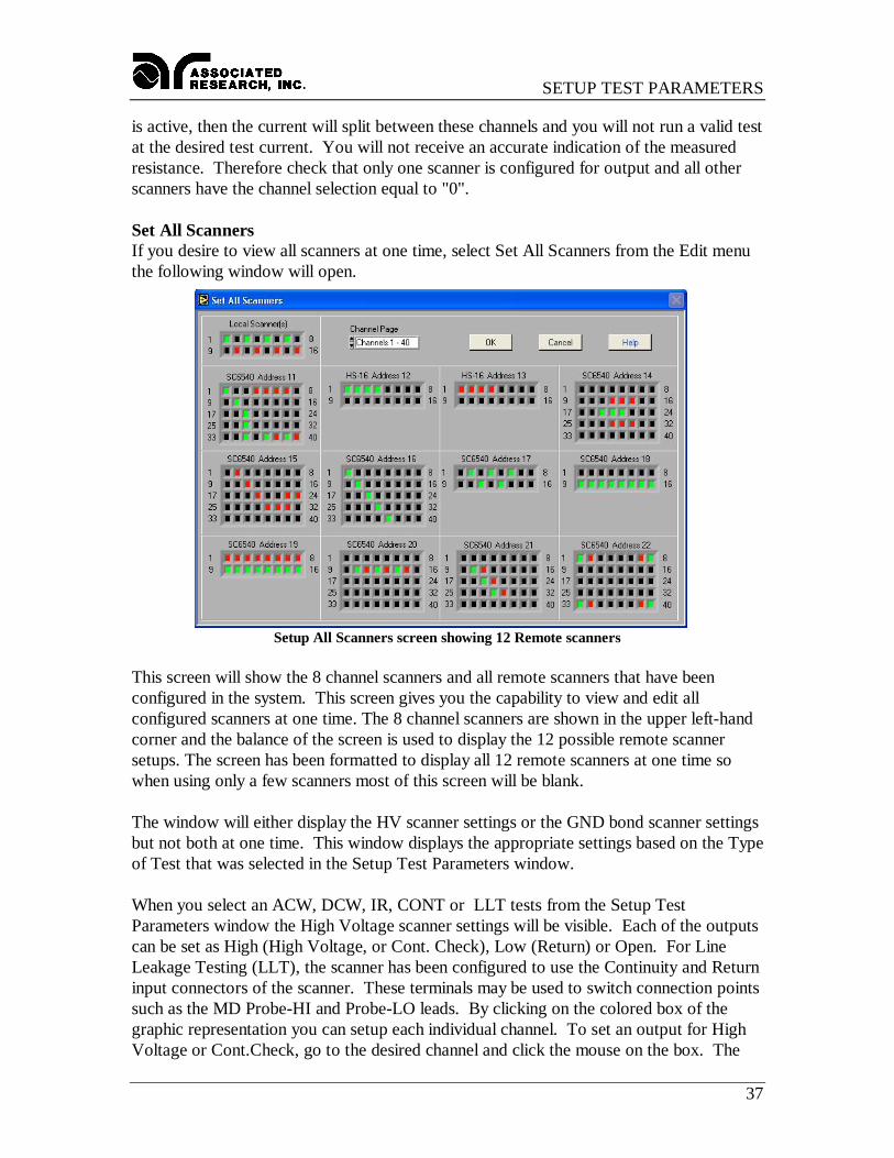
Set All ScannersIf you desire to view all scanners at one time, select Set All Scanners from the Edit menuthe following window will open.
Setup All Scanners screen showing 12 Remote scanners
This screen will show the 8 channel scanners and all remote scanners that have beenconfigured in the system. This screen gives you the capability to view and edit allconfigured scanners at one time. The 8 channel scanners are shown in the upper left-handcorner and the balance of the screen is used to display the 12 possible remote scannersetups. The screen has been formatted to display all 12 remote scanners at one time sowhen using only a few scanners most of this screen will be blank.
The window will either display the HV scanner settings or the GND bond scanner settingsbut not both at one time. This window displays the appropriate settings based on the Typeof Test that was selected in the Setup Test Parameters window.
When you select an ACW, DCW, IR, CONT or LLT tests from the Setup TestParameters window the High Voltage scanner settings will be visible. Each of the outputscan be set as High (High Voltage, or Cont. Check), Low (Return) or Open. For LineLeakage Testing (LLT), the scanner has been configured to use the Continuity and Returninput connectors of the scanner. These terminals may be used to switch connection pointssuch as the MD Probe-HI and Probe-LO leads. By clicking on the colored box of thegraphic representation you can setup each individual channel. To set an output for HighVoltage or Cont.Check, go to the desired channel and click the mouse on the box. The

SETUP TEST PARAMETERS
38
box will turn RED; indicating a High output. To set an output for Return go to thedesired channel and click the mouse on the box twice. The box will turn GREEN;indicating a Low position. When the box is BLACK the channel is "Open" or inactive.Clicking the mouse multiple times will change the color from Black to Red to Green andback to Black again in a continuous loop. Note: On scanner model HS-16 the Continuitymode is configured to run through the HV matrix (not Ground Bond). This mode requiresspecial connections to be made to the HS-16.
When you select a Ground Bond test (GND) from the Setup Test Parameters window theGround Bond scanner settings will be visible. Here you may select "0" which is thedefault that turns OFF all of the scanner channels, or you may select a number anywherefrom 1-8 if you have a single 8 Channel scanner or 1-16 for two 8 Channel scanners andthe HS-16 scanners or up to 80 channels for the SC6540. The number selected refers tothe output that will be active during the Ground Bond test. For example; if you select thenumber 8 then channel 8 will activate and supply high current during the Ground Bondtest and all other channels will be open or inactive on that scanner.
CAUTION: It is highly recommended that only one scanner be active at any time forGround Bond testing. The Ground Bond test is performed at a given test current so ifmore than one output channel is active, then the current will split between these channelsand you will not run a valid test at the desired test current. You will not receive anaccurate indication of the measured resistance. Therefore check that only one scanner isconfigured for output and all other scanners have the channel selection equal to "0".
Window MenuThe Window pull down menu consists of the 6 selections that will access 6 differentwindows that are described below. The window pull down menu is also duplicated on allof the windows that are accessible from the Window menu. Therefore direct access to anyone of these windows is available after one of the windows has been selected.
Setup System Parameters: This window is used to setup communication betweenAutoware and the PC. These software configuration windows do not requirecommunication with the actual test instrument(s). The remote indicators on theinstruments may not light during these setups.
File Manager: This window is used to manage the setup files. You can work with filesstored in the instrument memory or in the PC memory.
Setup Test Parameters: This window is used to setup and store test parameters as well asrecall test setups from existing files.
Run Tests: This window allows you to initiate and reset tests. You will also be able tomonitor results of the test. You can also use barcode scanning and load files from thiswindow.

SETUP TEST PARAMETERS
39
Remote Data Logging: This window primary use is to start test remotely whiles savingtest results to a file on the computer. There is no ability to start the test from this windowthrough the computer interface.
Examine Statistics: This window allows you to see actual test results and graph results bycategory.
RUN TESTS
40
RUN TESTS
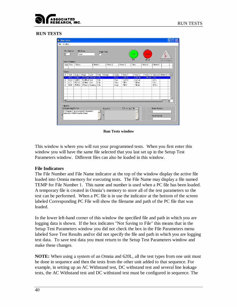
Run Tests window
This window is where you will run your programmed tests. When you first enter thiswindow you will have the same file selected that you last set up in the Setup TestParameters window. Different files can also be loaded in this window.
File IndicatorsThe File Number and File Name indicator at the top of the window display the active fileloaded into Omnia memory for executing tests. The File Name may display a file namedTEMP for File Number 1. This name and number is used when a PC file has been loaded.A temporary file is created in Omnia’s memory to store all of the test parameters so thetest can be performed. When a PC file is in use the indicator at the bottom of the screenlabeled Corresponding PC File will show the filename and path of the PC file that wasloaded.
In the lower left-hand corner of this window the specified file and path in which you arelogging data is shown. If the box indicates "Not Saving to File" this means that in theSetup Test Parameters window you did not check the box in the File Parameters menulabeled Save Test Results and/or did not specify the file and path in which you are loggingtest data. To save test data you must return to the Setup Test Parameters window andmake these changes.
NOTE: When using a system of an Omnia and 620L, all the test types from one unit mustbe done in sequence and then the tests from the other unit added to that sequence. Forexample, in setting up an AC Withstand test, DC withstand test and several line leakagetests, the AC Withstand test and DC withstand test must be configured in sequence. The
RUN TESTS
41
system cannot rotate between performing tests from an Omnia, then a 620L and then anOmnia again. All tests associated with a unit must be grouped together.
BarcodeThis window also has fields for Model and Serial number input. The data for these fieldscan be entered manually or automatically using a barcode scanner. To use the barcode itmust first be activated from the Barcode Scanner settings where the barcode can beenabled and the format can be configured. The "Barcode Scanner settings can be accessedfrom the Setup System Parameters window. When the barcode has been enabled thesection border around the Model and Serial Numbers will be labeled "Barcode Scanner".You may then scan Model number and or Serial number information before you initiate atest. Data will then be logged by model number and or serial number into the ExamineStatistics window and be recorded on the printed output.
Initiating a testThe TEST button is used to initiate a test. The Reset button that can be used as an abortswitch. The Test and Reset buttons can also be controlled from the keyboard directly bypressing the F4 function key for Test, and the escape key (Esc) for Reset.
If a prompt has been configured for a step, before the step begins a pop-up promptmessage window will appear on the screen near the test button. After any requiredprocedures or instructions are complete press the Test button again to continue the test.
As the test is being processed the live data will be displayed in the single row table labeledTest in Progress. It will show only data of the step that is being processed. The activestep will also be highlighted it the Results table.
The Results table will always indicate all the steps of the file in the first 7 columns. Thehighlighted row will move down the list as each test is processed and completed. Whenthe step is completed the results will fill into the remaining result columns for that step.All the results will be cleared at the beginning of the next test sequence.
File MenuLoad File: This menu item can be used to load a file the PC or from Omnia’s memory. Ifthe file is loaded from the PC a temporary file will be created in Omnia’s memory and thePC file name will be displayed in the Corresponding PC File indicator at the bottom of thewindow.
Print Preview: This menu item will show the results that will be printed. You can chooseto print the results or return to the Run window with out printing. If you did not printfrom the Preview window you can still print by selecting Print from the File menu. It willgenerate the print-out that was previewed.
Print: Will print the results directly to the printer without previewing the data.
RUN TESTS
42
Window MenuThe Window pull down menu consists of the 6 selections that will access 6 differentwindows that are described below. The window pull down menu is also duplicated on allof the windows that are accessible from the Window menu. Therefore direct access to anyone of these windows is available after one of the windows has been selected.
Setup System Parameters: This window is used to setup communication betweenAutoware and the PC. These software configuration windows do not requirecommunication with the actual test instrument(s). The remote indicators on theinstruments may not light during these setups.
File Manager: This window is used to manage the setup files. You can work with filesstored in the instrument memory or in the PC memory.
Setup Test Parameters: This window is used to setup and store test parameters as well asrecall test setups from existing files.
Run Tests: This window allows you to initiate and reset tests. You will also be able tomonitor results of the test. You can also use barcode scanning and load files from thiswindow.
Remote Data Logging: This window primary use is to start test remotely whiles savingtest results to a file on the computer. There is no ability to start the test from this windowthrough the computer interface.
Examine Statistics: This window allows you to see actual test results and graph results bycategory.
REMOTE DATA LOGGING
43
REMOTE DATA LOGGING
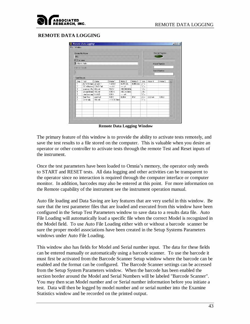
Remote Data Logging Window
The primary feature of this window is to provide the ability to activate tests remotely, andsave the test results to a file stored on the computer. This is valuable when you desire anoperator or other controller to activate tests through the remote Test and Reset inputs ofthe instrument.
Once the test parameters have been loaded to Omnia’s memory, the operator only needsto START and RESET tests. All data logging and other activities can be transparent tothe operator since no interaction is required through the computer interface or computermonitor. In addition, barcodes may also be entered at this point. For more information onthe Remote capability of the instrument see the instrument operation manual.
Auto file loading and Data Saving are key features that are very useful in this window. Besure that the test parameter files that are loaded and executed from this window have beenconfigured in the Setup Test Parameters window to save data to a results data file. AutoFile Loading will automatically load a specific file when the correct Model is recognized inthe Model field. To use Auto File Loading either with or without a barcode scanner besure the proper model associations have been created in the Setup Systems Parameterswindows under Auto File Loading.
This window also has fields for Model and Serial number input. The data for these fieldscan be entered manually or automatically using a barcode scanner. To use the barcode itmust first be activated from the Barcode Scanner Setup window where the barcode can beenabled and the format can be configured. The Barcode Scanner settings can be accessedfrom the Setup System Parameters window. When the barcode has been enabled thesection border around the Model and Serial Numbers will be labeled "Barcode Scanner".You may then scan Model number and or Serial number information before you initiate atest. Data will then be logged by model number and or serial number into the ExamineStatistics window and be recorded on the printed output.

REMOTE DATA LOGGING
44
This window allows you to review the test results of a single test or a sequence of tests upto Omnia’s maximum of 30 test results. The Test Results table is update only after thesequence of tests has been completed. The Test in Progress indicator on the top right ofthe window will illuminate green to show that tests are still running. When this indicatorgoes out the results will be update on the screen and to the results data file on thecomputer. All memories are cleared at the start of the next test cycle.
The file menu also provides capability to load files and print results directly through thecomputer interface if the environment is not 100% remote control and interaction with thePC is available.
Single StepThis screen does not have the ability to change the Single Step setting, and the Single Stepsetting can not be saved within a setup file. If it is desired to have the tester stop aftereach step then the Prompt function should be created in the Setup File or the Single Stepsetting should be setup manually on the instrument.
Window MenuThe Window pull down menu consists of the 6 selections that will access 6 differentwindows that are described below. The window pull down menu is also duplicated on allof the windows that are accessible from the Window menu. Therefore direct access to anyone of these windows is available after one of the windows has been selected.
Setup System Parameters: This window is used to setup communication betweenAutoware and the PC. These software configuration windows do not requirecommunication with the actual test instrument(s). The remote indicators on theinstruments may not light during these setups.
File Manager: This window is used to manage the setup files. You can work with filesstored in the instrument memory or in the PC memory.
Setup Test Parameters: This window is used to setup and store test parameters as well asrecall test setups from existing files.
Run Tests: This window allows you to initiate and reset tests. You will also be able tomonitor results of the test. You can also use barcode scanning and load files from thiswindow.
Remote Data Logging: This window primary use is to start test remotely whiles savingtest results to a file on the computer. There is no ability to start the test from this windowthrough the computer interface.
Examine Statistics: This window allows you to see actual test results and graph results bycategory.

EXAMINE STATISTICS
45
EXAMINE STATISTICS
Examine Statistics window
The statistics window is where you will review all data logging activity. When you firstenter this window you will be prompted to choose a path and a file for review. Select thefile you would like to review the statistics from and click OK. Again it is recommendedthat you store all your saved data in a similar file format, extension and directory.
Once you have selected the data file, the system defaults to a Summary of Tests view ofthe test data as shown in the window above. The current file's path and file name aredisplayed on the lower part of the window for easy monitoring. You may also displayselected information in graph format directly through the Examine Statistics mode inAutoware. This is done by selecting the test type, test result and step and then byselecting the parameter you wish to graph in the display field. The graph below is oneexample.
EXAMINE STATISTICS
46
Dates Filter: You may review test results within a certain time frame by checking the boxlabeled Dates Filter. After selecting this box you must enter a starting date and an endingdate in the appropriate fields. If no date range is specified than the default is all dateranges and all data will be displayed.
Serial Numbers Filter: You may review test results within a serial number range bychecking the box labeled Serial Numbers Filter. After selecting this box you must select astarting serial number and an ending serial number in the appropriate fields.
Model Numbers Filter: You may review test results within a model number range bychecking the box labeled Model Numbers Filter. After selecting this box you must select astarting model number and an ending model number in the appropriate fields.
Load File: Select this function from the File menu if you wish to view data from anotherfile. It will reopen the file window. As in the previous case just select the path and filename you wish to review.
Refresh: If the window was opened previous to executing tests then the data displayedwill not be current. Use the Refresh function to update the data for the currently loadedfile that is displayed in the Data File field at the bottom of the window.
Export File: Click on this key if you wish to use another program to view or modify thedata file. Exporting the data to another file will prevent the possible corruption to theoriginal data file. This export feature creates a tab delimited ASCII text file that can beread by other spreadsheet or word-processing program and modified for the end usersneeds.
Display: By clicking your mouse on the Down arrow you can see a range of selections forviewing data on the test type which has been selected.
Test Type: Here you select the type of test data that you wish to view depending upon theselected tests and model number of the instruments used. Selections may include, LineLeakage, Ground Bond, AC Withstand, DC Withstand, and IR test data.
Test Result: Here you can view pass, fail or all statistics presented in detailed, summary orgraphed format. Graphs are presented for all pass/fail statistics. The data is saved in astandard ASCII format so if you wish to graph your own results the data file may be easilyimported into any spreadsheet, word-processing or database program.
Step Number: You can also select data from specific steps in the file. This mode isparticularly useful in viewing if you know what type of test is associated with each step.Selections are for ALL individual step numbers that are available.

EXAMINE STATISTICS
47
Window MenuThe Window pull down menu consists of the 6 selections that will access 6 differentwindows that are described below. The window pull down menu is also duplicated on allof the windows that are accessible from the Window menu. Therefore direct access to anyone of these windows is available after one of the windows has been selected.
Setup System Parameters: This window is used to setup communication betweenAutoware and the PC. These software configuration windows do not requirecommunication with the actual test instrument(s). The remote indicators on theinstruments may not light during these setups.
File Manager: This window is used to manage the setup files. You can work with filesstored in the instrument memory or in the PC memory.
Setup Test Parameters: This window is used to setup and store test parameters as well asrecall test setups from existing files.
Run Tests: This window allows you to initiate and reset tests. You will also be able tomonitor results of the test. You can also use barcode scanning and load files from thiswindow.
Remote Data Logging: This window primary use is to start test remotely whiles savingtest results to a file on the computer. There is no ability to start the test from this windowthrough the computer interface.
Examine Statistics: This window allows you to see actual test results and graph results bycategory.

INFORMATION
48
Where to go if you need more Information
All versions of Autoware include help windows that will provide essentially the sameinformation that is included in this manual organized by window. If you still havequestions you can visit the Associated Research website at www.asresearch.com or emailus at [email protected]. You can also contact technical support by phone at1-800-858-TEST (847-367-4077 outside the U.S.) or by fax at 847-367-4080. Werequest that you have the following information ready when you call:
ü The model number of the instruments that you are controllingü The version number of the Autoware you are usingü If applicable, we need the exact wording of any error message that you receivedü The type of interface you are using (RS-232 or GPIB)ü If applicable, the make and model number of the GPIB controller card you are usingü The command you executed that caused the error and exactly when the error
occurred