user manual & setup guide · the a2-05 support socks4 and socks5 proxy servers; these can be...
TRANSCRIPT

Accsense A2-05 Series Temperature Monitor
User Manual & Setup Guide

GETTING STARTEDHardware Checklist...............................................................................3 Installing the A2-05...............................................................................4 - 5
IMPORTANT INFORMATIONLED Guide..............................................................................................6 IT Information........................................................................................7 Internet Security.....................................................................................8
SETUP & CONFIGURATION OF ACCSENSE SOFTWARE Login......................................................................................................9 Software Navigation..............................................................................10 - 11 Account Settings...................................................................................12 - 13 Latest Measurements...........................................................................14 Gateway Preferences Icon....................................................................15 - 16 Hiding the Thermocouple Reading.......................................................17 Gateway Alarms....................................................................................18 Sensor Preferences..............................................................................19 - 20 Sensor Alarms......................................................................................21 - 22
Sensor Graph........................................................................................23 - 27 Sequential Alarming………………………………………..............................………….28 - 29 Calibration Instructions........................................................................30 - 34 TROUBLESHOOTING.......................................................................35 - 36
TABLE OF CONTENTS
DataLoggerInc.com 2

HARDWARE CHECKLIST
D
C
E
B
A
A. A2-05 User GuideB. 2 x Ethernet Patch CablesC. Mains LeadD. Power AdapterE. A2-05 Unit
DataLoggerInc.com 3

2.1 Mounting the A2-05
The A2-05 can be mounted using the Velcro supplied.Make sure to place the A2-05 such that the End Plate (with the LEDs) is visible.
2.2 Insert the Probe
Place the temperature probe(s) into the area to be measured. If in a freezer, do this by either using the access port on the back of the freezer, or by running the lead through the door seal on the hinge side of the door. Secure the probe to a suitable fixed location e.g. Shelf, with a cable tie. Note: Remember, freezers and refrigerators are not the same temperature everywhere inside. Where you locate the probe WILL affect the reading. We recommend using a thermal dampener or liquid to simulate the product in the refrigerator/freezer.
2.3 Connect Probes to A2-05
Slide open the access door at the bottom of the A2-05. Insert the probes through the holes in the side of the case. The probe connection block shows connections for the 2 RTD and “T” type thermocouple probes. Push down the tab on the connector and insert the striped end of the probe into the connector, taking note of the colour.
NOTE: for RTD probes that have 2 red and 1 white wire, connect the white wire to the terminal marked RED and connect the 2 white wires to the terminals marked BLACK.
BLACKBLACKRED
BLACKBLACKRED
TC+ GND/TC-
RTD Probe number #1
RTD Probe number #2
‘T’ Type Thermocouple
Connector
INSTALLING THE A2-05
DataLoggerInc.com 4

For T type thermocouple probes the colour connections are: AMERICAN Colour Code INTERNATIONAL Colour Code BLUE TC+ BROWN TC+ RED TC- WHITE TC-
2.4 Connecting the Power Supply
Remove the A2-05 from the refrigerator/freezer by separating the Velcro. Slide open the access door on the bottom of the A2-05. Slide the On-Off switch to the On position
Follow Standard Power Supply or Power Over Ethernet instructions below.
Standard Power Supply
Connect the A2-05 to the Power Injector by inserting one end of an Ethernet cable into the port on the back of the A2-05 and the other into the OUT port of the Power Injector.
Next, insert the second Ethernet cable into the IN port of the Power Injector and connect the other end of the cable to a LAN port.
Plug the Power Injector into 100-240v AC mains using the power cord supplied
Power Over Ethernet (POE)
For Power-Over-Ethernet LANs, no Power Injector is necessary. Connect the A2-05 direct into the network which supports Power Over Ethernet (POE).
On
Off
INSTALLING THE A2-05
DataLoggerInc.com 5
LED GUIDE
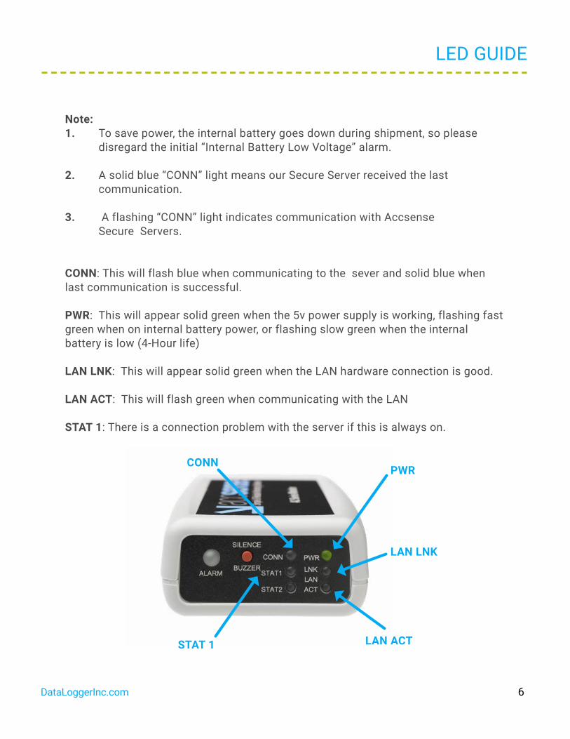
Note: 1. To save power, the internal battery goes down during shipment, so please disregard the initial “Internal Battery Low Voltage” alarm.
2. A solid blue “CONN” light means our Secure Server received the last communication.
3. A flashing “CONN” light indicates communication with Accsense Secure Servers.
CONN: This will flash blue when communicating to the sever and solid blue when last communication is successful.
PWR: This will appear solid green when the 5v power supply is working, flashing fast green when on internal battery power, or flashing slow green when the internal battery is low (4-Hour life)
LAN LNK: This will appear solid green when the LAN hardware connection is good.
LAN ACT: This will flash green when communicating with the LAN
STAT 1: There is a connection problem with the server if this is always on.
CONNPWR
LAN LNK
LAN ACTSTAT 1
DataLoggerInc.com 6

IT INFORMATION
As shipped the Accsense A2-05 is plug and play with the following settings: • The server is DHCP. • A Proxy server is not being used. • The MAC address does not require registering.
The A2-05 can be set with a fixed IP address, this can be done with the Remote Gateway Configuration Utility which can be downloaded from the following link: http:// www.accsense.com/software
Note: The IP, DNS and Gateway address all need to be entered correctly for the A2-05 communicate with the server correctly.
The A2-05 support SOCKS4 and SOCKS5 Proxy servers; these can be setup using the Remote Gateway Configuration Utility. In environments where other proxy servers are used an exemption to port 443 outbound on the router/firewall will be required to allow the unit to communicate directly with Grant/Accsense Servers.
Generally MAC numbers do not require registering on the network, if it is a requirement simply register the unique MAC number for each A2-05.
All communication with Accsense Servers is initiated from the Accsense unit over HTTPS on port 443 using 128 bit encryption, to guarantee integrity and confidential-ity. The units do not accept incoming connections from Accsense Servers; they only need to be able to initiate outbound connections to upload data.
All traffic is initiated from the A2–05 as out going secure web requests.
Aside from needing access to DNS servers, the A2-05 will not communicate with any other hosts on the Internet.
Useful destination addresses for communications for the A2-05 web application are as follows:
secure.sensornetworkonline.com 104.193.19.181listener.sensornetworkonline.com 104.193.19.182
Please note that these addresses may change from time to time. If necessary contact our support staff for a current list of addresses.
The above web addresses may need to be added to the whitelist in the firewall to allow outgoing communication to the Accsense sever.
DataLoggerInc.com 7

INTERNET SECURITY
Communication from the A2-05 to the Accsense Secure Servers utilizes the HTTPS protocol and only relies on an outbound connection over port 443. As communication between the A2-05 and the servers is initiated from the A2-05, there is no need to open inbound ports on the firewall. HTTPS over port 443 is a standard communications protocol for secure Web traffic (e.g. credit card transactions).
Data sent over the Internet utilizes two forms of encryption:
1) SSL Encryption, the same "padlock" feature that many Web sites use to en sure Web purchases are secure. 2) Certificate Encryption, each gateway is issued a unique, digitally signed certificate that is associated with its serial number.
A combination of SSL and Certificate Encryption ensures the data has the highest level of security over the internet, as only devices with certificates containing this digital signature are permitted to connect to the Grant/Accsense Servers. Our Website is VeriSign Secured®, providing leading encryption and identity verification.
If a certificate is ever compromised, its unique signature can be revoked, making this virtually un-exploitable to system crackers. These two forms of encryption prevent security problems such as Denial of Service attacks. Secondly, it is virtually impossible to maliciously insert or spoof data - ensuring accurate data, every time.
DataLoggerInc.com 8

LOGIN
6.1 Creating your Account
Your Accsense web service account is created automatically as soon as the A2-05 contacts the Grant/Accsense secure server (solid blue LED on the front of the A2-05). The account will not exist and you will NOT be able to log in until the first successful communication contact with the Accsense server.
You can login to your account via the "Custom Login" link at www.accsense.com
6.2 Login to your Account
You can login to your account with the Gateway MAC number (found on the side of the A2-05) and the default Login Name and Password:
Login Name: AdminPassword: Admin
Note: Both the Login Name and Password are Case Sensitive.
Your PC will remember the Gateway Mac number if you check the box.
DataLoggerInc.com 9

SOFTWARE NAVIGATION
On the initial login you will be required to accept the terms and conditions and create new passwords for the admin and reader user accounts. Once you have logged in, Accsense software is extremely easy to navigate. From the main screen clicking on the icons brings up pop up windows. Note: the browser must be set to allow pop ups from the Grant/Accsense web site.
Closing a pop up window returns the user to the main screen.
DataLoggerInc.com 10

SOFTWARE NAVIGATION
The main screen has four areas:
1. User Information/Account Settings2. Triggered Alarms3. Latest Measurements4. Alarm History
1
23 4
DataLoggerInc.com 11

ACCOUNT SETTINGS
The Account Settings pop up has three tabs.
8.1 Primary Contact
The Primary Contact tab provides information that can be used by Accsense if the need arises to contact the customer for any reason. It is important for the users to keep this information up to date.
8.2 User Accounts
The User Accounts tab allows two levels of system access to be created Administrator and Read Only.
Administrator - Can change any parameters, such as alarm levels, the details of the alarm contacts etc.
Reader - Can only view the information from the system, but cannot change any system parameters.
If the Administrator forgets their password, contact Accsense to have the password reset.
DataLoggerInc.com 12
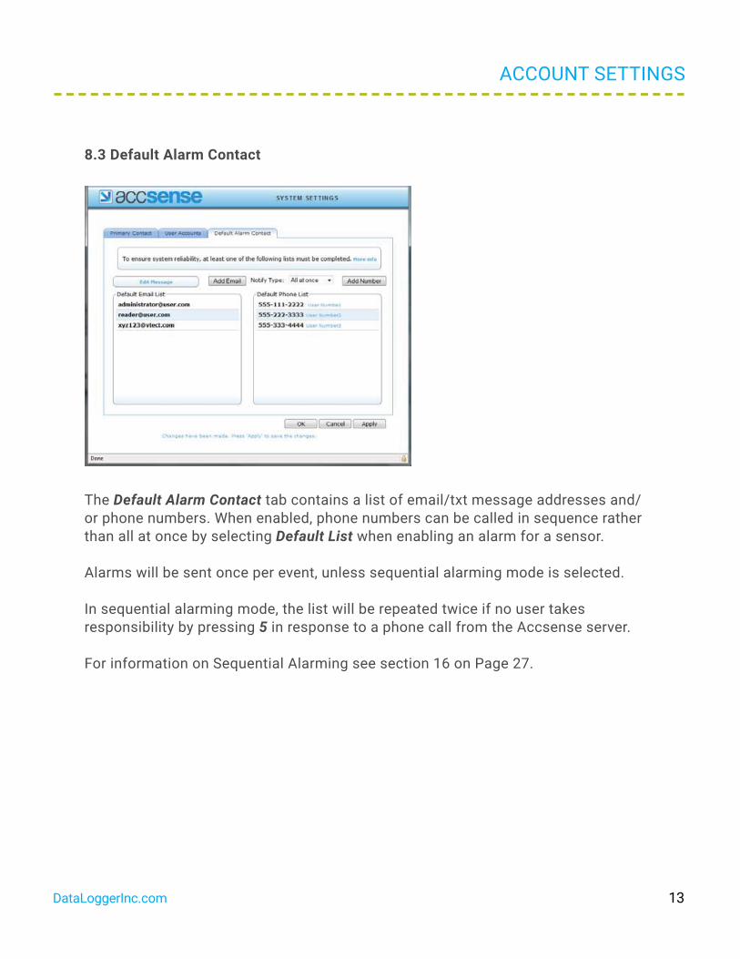
8.3 Default Alarm Contact
The Default Alarm Contact tab contains a list of email/txt message addresses and/or phone numbers. When enabled, phone numbers can be called in sequence rather than all at once by selecting Default List when enabling an alarm for a sensor.
Alarms will be sent once per event, unless sequential alarming mode is selected.
In sequential alarming mode, the list will be repeated twice if no user takes responsibility by pressing 5 in response to a phone call from the Accsense server.
For information on Sequential Alarming see section 16 on Page 27.
ACCOUNT SETTINGS
DataLoggerInc.com 13
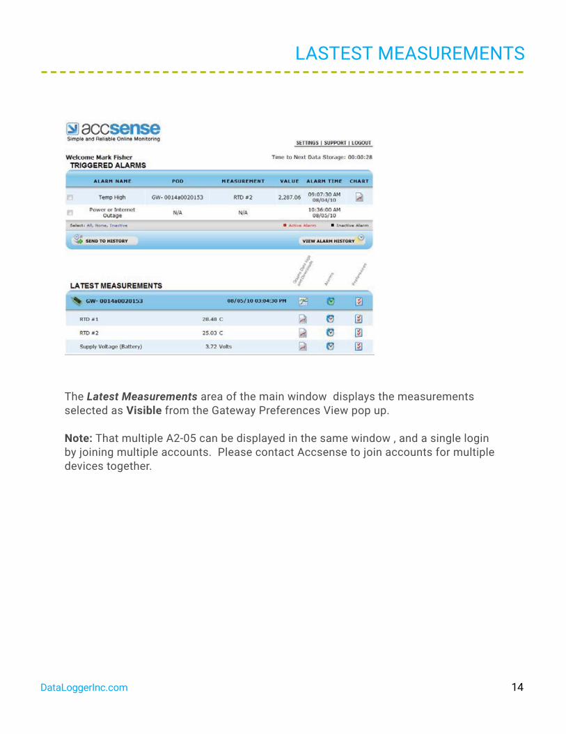
The Latest Measurements area of the main window displays the measurements selected as Visible from the Gateway Preferences View pop up.
Note: That multiple A2-05 can be displayed in the same window , and a single login by joining multiple accounts. Please contact Accsense to join accounts for multiple devices together.
LASTEST MEASUREMENTS
DataLoggerInc.com 14

The General tab allows the users to name the A2-05 (A2-05 will be listed on the screen in alphabetical order), set the sampling rates (how often measurements are made) and record notes about the A2-05.
Two different sample rates can be selected: Store data every - Records data if the measurements are within limits usually slower Check for alarm every - checks measurements against alarm limits, usually faster
GATEWAY PREFERENCES ICON
DataLoggerInc.com 15

GATEWAY PREFERENCES ICON
10.2 Info tab
The Info tab provides information about the A2-05 and firmware. This information can be useful when diagnosing system problems remotely.
8.2 User Accounts
View tab allows users to set which measurements are:
- Visible (Shown in measurement window)
- Hidden (recorded but not displayed)
- Disabled (Not recorded or displayed)
DataLoggerInc.com 16

HIDING THE THERMOCOUPLE READING
To hide or disable the thermocouple reading click on the Gateway Preference Icon. Select the View tab.
The thermocouple readings then be Disabled or Hidden by checking the appropriate box. Then click on OK.
The Thermocouple reading will now not be displayed in the Latest Measurements of the Gateway.
DataLoggerInc.com 17

GATEWAY ALARMS
The Gateway Alarm window allows users to set alarms which are triggered if the Accsense secure remote servers lose contact with the A2–05.
Note: Only ONE alarm is issued in the event of communication being lost.
DataLoggerInc.com 18
SENSOR PREFERENCES
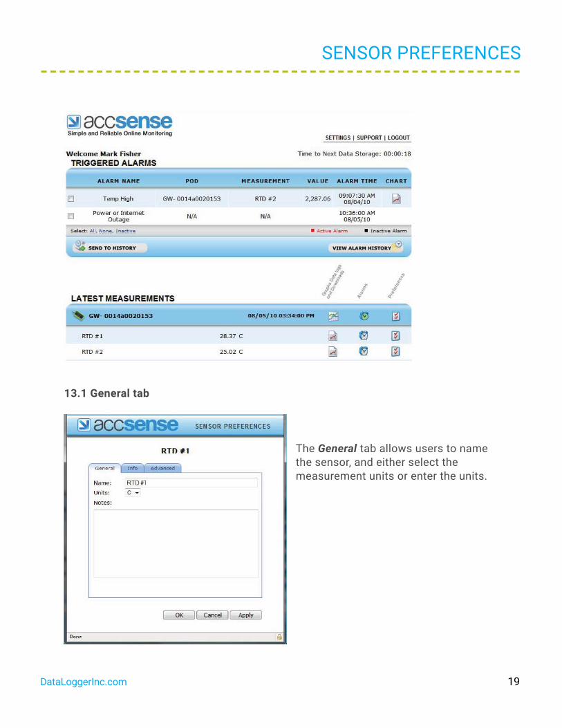
13.1 General tab
The General tab allows users to name the sensor, and either select the measurement units or enter the units.
DataLoggerInc.com 19

13.2 Info tab
The Info tab provides information about the sensor: Type of Sensor and measurement units
13.3 Advanced tab
The Advanced tab provides calibration information about the sensor. The calibration offset can be used to adjust the temperature to match other displays. Information on this can be found in Section 16 Calibration Instruction. (Page 30)
SENSOR PREFERENCES
DataLoggerInc.com 20
SENSOR ALARMS
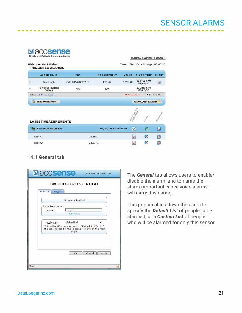
14.1 General tab
The General tab allows users to enable/ disable the alarm, and to name the alarm (important, since voice alarms will carry this name). This pop up also allows the users to specify the Default List of people to be alarmed, or a Custom List of people who will be alarmed for only this sensor
DataLoggerInc.com 21
SENSOR ALARMS
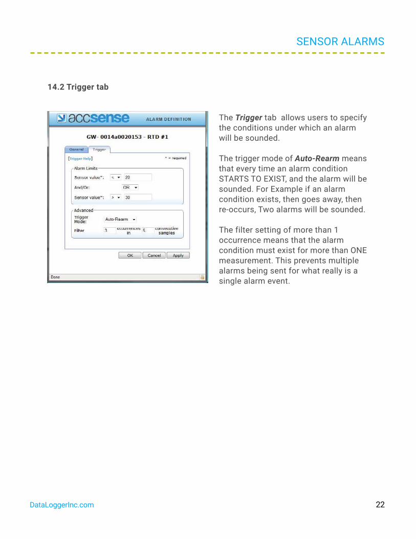
14.2 Trigger tab
The Trigger tab allows users to specify the conditions under which an alarm will be sounded. The trigger mode of Auto-Rearm means that every time an alarm condition STARTS TO EXIST, and the alarm will be sounded. For Example if an alarm condition exists, then goes away, then re-occurs, Two alarms will be sounded. The filter setting of more than 1 occurrence means that the alarm condition must exist for more than ONE measurement. This prevents multiple alarms being sent for what really is a single alarm event.
DataLoggerInc.com 22

SENSOR GRAPH
15.1 Main Graph
The Sensor Graph Icon brings up a pop up graph with a default time window of 1 day. Statistics for the data displayed are located across the top of the graph. If alarms are set, red bars will appear across the graph at the one or two alarm levels set.
DataLoggerInc.com 23
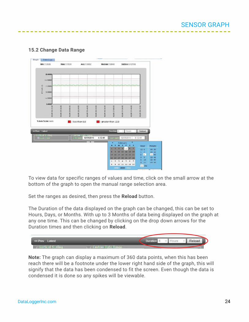
15.2 Change Data Range
To view data for specific ranges of values and time, click on the small arrow at the bottom of the graph to open the manual range selection area. Set the ranges as desired, then press the Reload button.
The Duration of the data displayed on the graph can be changed, this can be set to Hours, Days, or Months. With up to 3 Months of data being displayed on the graph at any one time. This can be changed by clicking on the drop down arrows for the Duration times and then clicking on Reload.
Note: The graph can display a maximum of 360 data points, when this has been reach there will be a footnote under the lower right hand side of the graph, this will signify that the data has been condensed to fit the screen. Even though the data is condensed it is done so any spikes will be viewable.
SENSOR GRAPH
DataLoggerInc.com 24

15.3 Multiple Traces on a Graph
It is possible to display more than one trace on a graph for each A2-05, this could be used to compare temperature graphs from two different probes. In the Latest Measurements click on the graph icon for the A2-05
In the Multi Sensor Selection highlight the required sensors to be displayed. This is done by holding down Ctrl and click on the sensors. When the sensors required are highlighted click on Draw Chart.
SENSOR GRAPH
DataLoggerInc.com 25

SENSOR GRAPH
The multiple traces will then be displayed on the graph as below, the date range can then be changed as required.
DataLoggerInc.com 26

SENSOR GRAPH
15.4 Download to Excel
To download the data shown on the graph to an Excel spreadsheet (.csv format), simply press the Download Selected Data button at the top right of the screen.
To view the data as a table, click on the Data Logs tab and scroll through the data. The time stamp on the data is the time the data was recorded.
DataLoggerInc.com 27

SEQUENTIAL ALARMING
16.1 Sequential Alarming
Sequential alarming can only be set if the User has a Level 3 account and is using the voice alarm notification.
Sequential alarming can either be set in the Default Alarm Contacts or the Phone Lists for the individual A2-05 or for the Sensor Alarms.
Change the Notify Type to In sequence
Each phone number on the list will be dialed in sequence until a response has been received that a recipient is going to take responsibility for the alarm notification. The user takes responsibility for the alarm by pressing 5 in response to a call from the Accsense server.
The phone list will be repeated twice if no user takes responsibility for the alarm.
16.2 Voice Notification Script
The voice notification comprises of the following script.
This is an alarm notification from your Accsense wireless monitoring system.
The (sensor name) sensor on Pod (pod name) reported a (alarm name) alarm at date/time, in (your local time zone) time.
Sensor value is value
I repeat the (sensor name) sensor on Pod (pod name) reported a (alarm name) alarm at date/time, in (your local time zone) time.
Sensor value is value
DataLoggerInc.com 28

Please login to your Accsense account at www.accsense.com for details
Please press 5 to acknowledge receipt. [When 5 is pressed] You have now taken responsibility for this alarm. Thank you, Goodbye.
All (bracketed) values are read from the user-configured settings for each pod. If you change the name of a sensor or pod, it will read in the message. All bold values are read from the actual stored data that triggered the alarm, which may not be the most recent data point.
In the case of a filtered alarm (X occurrences in Y samples), the alarm will read off the time stamp and value of the most recent data point, the one which triggered the alarm.
SEQUENTIAL ALARMING
DataLoggerInc.com 29

CALIBRATION INSTRUCTIONS
17.1 Calibration RequirementsThe calibration requirements for the A2-05 will depend on the Quality processes of the end user, generally this would be once a year.
17.2 Single Point Calibration If the temperature being measured is always going to be around the same value ±5°C then all that is need is a single point calibration.
Requirements
• A2-05
• Temperature probe connected to the A2-05
• Accsense software - access to Accsense software including login & password.
• Calibrate temperature source/thermometer
DataLoggerInc.com 30
Calibration InstructionsIn the Sensor Preferences make sure the Calibration Offset is set to 0.0 and the Calibration Gain is set to 1.0
This is done by clicking on the Preferences Icon for that probe. In the Sensor Preferences window click on the Advanced Tab, and then enter the two values.
• Set the temperature source to the required temperature (this will need to be the temperature that is being permanently measured) if it is not calibrated verify
using a thermometer.
• Place the temperature probe installed in the Grant/Accsense A2-05 into the temperature source and allow to settle down, this may take a while.
• Take a note of the temperature of the temperature/thermometer and the temperature probe connected to the A2–05 through the Grant/Accsense web service.
• If both readings are the same then the calibration of the A2-05 is correct.
• If there is a difference between the two readings then work out the value of the temperature source reading – the A2-05 reading.
• This value now needs to be entered into the Grant/Accsense web service for that probe. This is done by clicking on the Preferences Icon for that probe. In the Sensor Preferences window click on the Advanced Tab. Enter the value of the difference between the two readings into the Calibration Offset box. Note: The Calibration Gain stays as 1.0
Example: if the Source reading is 25.00°C and the A2-05 reading is 22.80°C. The Calibration Offset would be 25.00 – 22.80 = 2.2°C (2.2 is the value entered into the Calibration Offset box as on the next page)
CALIBRATION INSTRUCTIONS
DataLoggerInc.com 31

CALIBRATION INSTRUCTIONS
If the other sensors need calibrating on the A2-05 they are done in the same way.
17.3 Two Point CalibrationIf the temperature being measured is across a range (for example between +25°C and -25° C) then a two point calibration should be used.
Requirements
• A2-05
• Temperature probe connected to the A2-05
• Grant/Accsense software - access to Accsense software including login & pass-word.
• Calibrate temperature source/thermometer
Calibration InstructionsIn the Sensor Preferences make sure the Calibration Offset is set to 0.0 and the Calibration Gain is set to 1.0
This is done by clicking on the Preferences Icon for that probe. In the Sensor Preferences window click on the Advanced Tab, and then enter the two values.
• Set the temperature source to the required temperature (this will need to be the temperature that is being permanently measured) if it is not calibrated verify
using a thermometer.
• Place the temperature probe installed in the A2-05 into the temperature source and allow to settle down, this may take a while.
DataLoggerInc.com 32

• Take a note of the temperature of the temperature/thermometer and the temperature probe connected to the A2-05 through the Accsense web service. Note: This needs to be done at the two calibration points that are required.
• When there are two points then the gain needs to be worked out first which can be found from (higher calibration point – lower calibration point) / (higher A2-05 value – lower A2-05 value).
For example, if the calibration points are 25.00°C and 73.00°C, and the A2-05 reads 26.25°C and 76.25°C, then the gain is (73.00 – 25.00) / (76.25 – 26.25) = 48.00 / 50.00 = 0.96.
• Next the offset needs to be calculate by multiplying either (or both) of the A2-05 values by the gain and then subtracting that from the calibration value as before.
Carrying on with the above example, 26.25* 0.96 = 25.20°C and 25.00 – 25.20 = -0.20°C and similarly 76.25 * 0.96 = 73.20 and 73.00 – 73.20 = -0.20°C so the offset is still -0.20° C. If there are two different answers (allowing for rounding errors) then please check your calculations.
17.4 Using Excel to do the calculationBy using excel to do the calculation a multi point (two or more) calibration can be achieved using linear regression (least squares linear regression).
• As above take the calibration reading and the A2-05 readings, and then using lin-ear regression (least squares linear regression) on a computer is the best to find the Offset and Gain values.
• Using Excel, enter two columns of figures with the calibration values in the left hand column and the A2-05 values in the right hand column. Next highlight two cells where the result is to appear and use the array function LINEST to calculate the least squares result.
CALIBRATION INSTRUCTIONS
DataLoggerInc.com 33

Note: that it is an array function so press CTRL+SHIFT+ENTER to make it produce both results. An example is shown below.
• These values need to be entered into the Accsense web service for that probe.
This is done by clicking on the Preferences Icon for that probe. In the Sensor Preferences window click on the Advanced Tab. Enter the Offset value into the Calibration Offset box and the gain value into the Calibration Gain box
The example figures can be seen in the Sensor Preferences window below.
If the other sensors need calibrating on the A2-05 they are done in the same way.
CALIBRATION INSTRUCTIONS
Calibration A2-05
values values
25.00 26.25
55.005 7.5073.007 6.25
gain offset
0.96 - 0.20
DataLoggerInc.com 34

TROUBLESHOOTING
There is a problem with the Ethernet port that the A2-05 is plugged into.
• If this is a new installation, verify the Ethernet connection is active.
- On the A2-05 there is a LINK LED on the front. If there is a hardware connection, the LED will be illuminated. If the LED is not illuminated, verify the connection by removing the cable from the A2-05 and plug it into a computer to make sure that the Ethernet port is active.
The facility does not use DHCP
• If the network uses static IP addresses instead of DHCP, the A2-05 will not be able to obtain initial IP address, DNS or gateway information.
- On the A2-05 the STAT1 LED will be on to indicate that there is a problem connecting to the server.
The solution is to use the Remote Gateway Configuration tool to establish a local connection to the A2-05 and manually configure it. The tool can be downloaded from the following webpage: http://www.accsense.com/software.
Download this program and install it on a PC that is on the same subnet as the A2-05. Start the program and it will search the local network for any Grant/Accsense system. If it finds them, they will be displayed in the list box on the left of the configuration tool. Click on the MAC address of the A2-05 that requires configuration, go to the IP tab and uncheck “Obtain Network Address Automatically”. Then, fill in the IP address that you want to assign to the A2-05 along with the subnet mask, at least one DNS address and the route or gateway address.
Note: the A2-05 may take several tries, as this unit will keep rebooting in an attempt to get an address.
DataLoggerInc.com 35

TROUBLESHOOTING
The alternative to programming the A2-05 with the IP address, subnet mask and DNS address is to connect the A2-05 directly to the PC Ethernet port using a cross over cable. Once connected the Remote Gateway Configuration tool can be used as described above. This is a much easier way to program the A2-05 as the unit does not repeatedly reboot its self.
Once this is done, click the submit changes button to save the settings in the A205. This will then restart with the new settings and after about a minute it should show up in the Gateway Configuration software. Verify that the new settings are correct and check to see that the Connect LED is on for the A2-05.
The facility uses a Proxy server for communication to the Internet.
• Just like configuring the IP address, use the Remote Gateway Configuration soft-ware to enter the information for the Proxy server. Click on the Proxy tab and enter the information for your server.
The facility has blocked outgoing communications.
There are several possibilities:
• Port 443 in the firewall between the local network and the internet is blocked. The IT department will be required to open port 443 for HTTPS communication.
• Unsolicited outgoing communications for the facility to the internet is blocked. This may have been done to prevent malicious software from sending data out. The IT department will need to add the address of the Accsense servers to the whitelist in the firewall this is to allow the outgoing communications from the system to pass through.
Useful destination addresses for communications for the A2-05 web application are as follows:
secure.sensornetworkonline.com 104.193.19.181 listener.sensornetworkonline.com 104.193.19.182
DataLoggerInc.com 36

8437 Mayfield Rd Unit 104, Chesterland, OH 44026
1-800-956-4437
Visit DataLoggerInc.comFor More Accsense Monitoring Systems