user manual modular v -...
TRANSCRIPT

ARTURIA – Modular V – USER MANUAL 1
USER MANUAL

ARTURIA – Modular V – USER MANUAL 2
Direction
Frédéric Brun Kevin Molcard
Development
Stefano D'Angelo
Baptiste Aubry
Corentin Comte
Baptiste Le Goff
Pierre-Lin Laneyrie
Valentin Lepetit
Samuel Limier
Germain Marzin
Mathieu Nocenti
Pierre Pfister
Benjamin Renard
Design
Glen Darcey
Yannick Bonnefoy
Morgan Perrier,
Sebastien Rochard
Greg Vezon
Sound Design
Glen Darcey
Goeff Downes
Clay Duncan
Clay Duncan
Celmar Engel
Boele Gerkes
Victor Morello
Chris Pittman
Klaus Peter Rausch
Klaus Schulze
Katsunori Ujiie
Manual
Jason Valax
Special Thanks
Alejandro Cajica
Denis Efendic
Ruary Galbraith
Dennis Hurwitz
Clif Johnston
Koshdukai
Joop van der Linden
Sergio Martinez
Shaba Martinez,
Miguel Moreno
Daniel Saban
Carlos Tejeda,
Scot Todd-Coate
© ARTURIA S.A. – 1999-2016 – All rights reserved.
11 Chemin de la Dhuy
38240 Meylan
FRANCE
http://www.arturia.com

ARTURIA – Modular V – USER MANUAL 3
Table of Contents
1 INTRODUCTION ................................................................................................................. 7
1.1 The birth of the Bob Moog’s modular systems .................................................................................. 7
1.2 A modular synthesizer, why? .............................................................................................................. 12
1.3 Arturia’s secret ingredient: TAE® ........................................................................................................ 13
1.3.1 Aliasing-free oscillators ................................................................................................................... 13
1.3.2 A better reproduction of analog oscillator waveforms................................................................. 14
1.3.3 Direct Filter Circuit Modeling .......................................................................................................... 15
2 ACTIVATION AND FIRST START ...................................................................................... 17
2.1 Register and Activate .......................................................................................................................... 17
2.2 Initial setup ............................................................................................................................................. 17
2.2.1 Audio and MIDI settings: Windows ................................................................................................. 17
2.2.2 Audio and MIDI settings: Mac OS X ............................................................................................... 19
2.2.3 Using Modular V in plug-in mode ................................................................................................... 20
3 USER INTERFACE .............................................................................................................. 21
3.1 The virtual keyboard ............................................................................................................................ 21
3.2 Toolbar .................................................................................................................................................... 21
3.2.1 Save Preset ..................................................................................................................................... 21
3.2.2 Save Preset As… ............................................................................................................................. 22
3.2.3 Import preset .................................................................................................................................. 22
3.2.4 Export preset ................................................................................................................................... 22
3.2.5 Export bank ..................................................................................................................................... 22
3.2.6 Resize window options ................................................................................................................... 22
3.2.7 Audio settings ................................................................................................................................. 23
3.2.8 Preset browser overview ................................................................................................................ 23
3.2.9 MIDI Learn assignment ................................................................................................................... 24
3.2.9.1 Assigning / unassigning controls .......................................................................................................................... 25
3.2.9.2 Min / Max value sliders .......................................................................................................................................... 26
3.2.9.3 Relative control option.......................................................................................................................................... 26
3.2.9.4 Reserved MIDI CC numbers ................................................................................................................................. 26
3.2.10 MIDI controller configuration.......................................................................................................... 27
3.2.11 The lower toolbar ............................................................................................................................ 27
3.2.11.1 Current control value ............................................................................................................................................ 27
3.2.11.2 Midi Channel Setting ............................................................................................................................................. 28
3.2.11.3 Panic button and CPU meter .............................................................................................................................. 28
3.3 The Preset Browser ................................................................................................................................ 29
3.3.1 Searching presets ........................................................................................................................... 29
3.3.2 Using tags as a filter ........................................................................................................................ 29
3.3.3 The Preset Info section .................................................................................................................... 31
3.3.4 Preset selection: other methods..................................................................................................... 31
3.3.4.1 Selecting a preset by its Type .............................................................................................................................. 33
3.3.5 Playlists ............................................................................................................................................ 33
3.3.5.1 Add a playlist .......................................................................................................................................................... 33

ARTURIA – Modular V – USER MANUAL 4
3.3.5.2 Add a preset ........................................................................................................................................................... 34
3.3.5.3 Re-order the presets .............................................................................................................................................. 34
3.3.5.4 Remove a preset ................................................................................................................................................... 34
3.3.5.5 Delete a playlist ...................................................................................................................................................... 34
3.4 Overview of the 4 sections of the Modular V ................................................................................. 34
3.4.1 The synthesis section ....................................................................................................................... 35
3.4.2 The other three sections ................................................................................................................. 35
3.5 Modular synthesizer .............................................................................................................................. 36
3.5.1 Description of the synthesis section modules ................................................................................ 37
3.5.1.1 The oscillators .......................................................................................................................................................... 37
3.5.1.2 The white and pink noise generator ................................................................................................................... 38
3.5.1.3 The filters .................................................................................................................................................................. 38
3.5.1.4 The auxiliary ADSR modulation envelopes......................................................................................................... 39
3.5.1.5 The dual trigger delay ........................................................................................................................................... 39
3.5.1.6 The LFOs ................................................................................................................................................................... 40
3.5.1.7 The VCAs ................................................................................................................................................................. 41
3.5.1.8 Mixers and amplifiers ............................................................................................................................................. 41
3.6 The other sections................................................................................................................................. 42
3.6.1 The sequencer ................................................................................................................................ 42
3.6.2 The effects ...................................................................................................................................... 43
3.6.2.1 The fixed filter bank ................................................................................................................................................ 44
3.6.2.2 The “Dual delay” .................................................................................................................................................... 45
3.6.2.3 The chorus ............................................................................................................................................................... 46
3.6.3 The keyboard controllers ................................................................................................................ 46
3.6.4 The play modes .............................................................................................................................. 47
3.6.5 The sound design controllers .......................................................................................................... 48
3.6.5.1 The envelope control sliders ................................................................................................................................. 49
3.6.5.2 The 2D Pads ............................................................................................................................................................ 49
3.6.5.3 The filter cutoff frequency controller .................................................................................................................. 50
4 The modules in details ................................................................................................... 51
4.1 Programming section .......................................................................................................................... 51
4.1.1 Description ...................................................................................................................................... 51
4.1.2 Oscillators ........................................................................................................................................ 51
4.1.2.1 Controller 921A ....................................................................................................................................................... 52
4.1.2.2 Slave oscillator 921B............................................................................................................................................... 54
4.1.3 Filters................................................................................................................................................ 56
4.1.3.1 Low pass 24 dB/octave filter (904A) ................................................................................................................... 57
4.1.3.2 High-pass 24 dB/octave filter (904B) ................................................................................................................... 58
4.1.3.3 Band-pass 24 dB/octave filter (904C) ................................................................................................................. 59
4.1.3.4 Multi-mode 12 dB/octave filter ............................................................................................................................ 60
4.1.4 Modulation envelopes ................................................................................................................... 62
4.1.5 Output amplifiers (VCA) ................................................................................................................. 64
4.1.6 Low frequency oscillators (LFO) ..................................................................................................... 66
4.1.7 Controlled amplifiers / Mixers ......................................................................................................... 67
4.1.8 Trigger delay ................................................................................................................................... 68
4.1.9 Noise generator .............................................................................................................................. 70

ARTURIA – Modular V – USER MANUAL 5
4.1.10 Sample and hold ............................................................................................................................ 71
4.1.11 Envelope follower ........................................................................................................................... 72
4.1.12 Ring modulator ............................................................................................................................... 73
4.1.13 Formant filter ................................................................................................................................... 74
4.1.14 Bode Frequency Shifter .................................................................................................................. 75
4.2 Second section ..................................................................................................................................... 76
4.2.1 Description ...................................................................................................................................... 76
4.2.2 Resonant filter bank ........................................................................................................................ 76
4.2.3 Chorus ............................................................................................................................................. 77
4.2.4 Phaser ............................................................................................................................................. 78
4.2.5 Stereo Delay ................................................................................................................................... 80
4.2.6 Sequence generator ...................................................................................................................... 81
4.3 Third Section .......................................................................................................................................... 85
4.4 Fourth section ........................................................................................................................................ 85
4.4.1 Keyboard follow management ..................................................................................................... 86
4.4.2 General settings.............................................................................................................................. 87
5 The basics of subtractive synthesis ............................................................................. 89
5.1 The three main modules ..................................................................................................................... 89
5.1.1 The oscillator or VCO ...................................................................................................................... 89
5.1.2 The filter or VCF ............................................................................................................................... 93
5.1.3 The amplifier or VCA....................................................................................................................... 97
5.2 Complementary modules .................................................................................................................. 98
5.2.1 The envelope generator ................................................................................................................ 98
5.2.2 The low frequency oscillator .......................................................................................................... 99
6 A few elements of sound design .............................................................................. 102
6.1 Modular sound synthesis ................................................................................................................... 102
6.1.1 Simple patch #1 ............................................................................................................................ 102
6.1.2 Simple patch #2 ............................................................................................................................ 104
6.1.3 Complex patch #1 ........................................................................................................................ 108
6.1.4 Complex patch #2 ........................................................................................................................ 111
6.2 The sequencer .................................................................................................................................... 115
6.2.1 Sequence #1 ................................................................................................................................. 115
6.2.2 Sequence #2 ................................................................................................................................. 117
6.2.3 Sequence #3 ................................................................................................................................. 120
6.3 Bonus features ..................................................................................................................................... 121
6.3.1 Creative use of key follows ........................................................................................................... 121
6.3.2 Creative use of triggers and trigger delays .................................................................................. 123
6.3.3 Stereo without the effects ............................................................................................................. 124
6.3.4 The Bode Frequency Shifter .......................................................................................................... 126
6.3.4.1 More stereo width ................................................................................................................................................ 126
6.3.4.2 Electronic percussion sequence ....................................................................................................................... 127
6.3.5 The Envelope Follower ................................................................................................................... 128
6.3.5.1 Trig by an external audio source. ...................................................................................................................... 129
6.3.5.2 Create your LFO form .......................................................................................................................................... 130

ARTURIA – Modular V – USER MANUAL 6
6.3.6 The sample and hold..................................................................................................................... 131
7 END USER LICENSE AGREEMENT ................................................................................ 133

ARTURIA – Modular V – USER MANUAL 7
1 INTRODUCTION
Arturia would like to thank you for purchasing our synthesizer model: the Modular
V. We are confident it will prove to be an extremely valuable addition to your music
production studio. If you’ve purchased our products before, you know we pride
ourselves in faithfully recreating the sound and feel of the original instruments, down
to the smallest detail. Modular V is no exception to this rule.
And if this is the first of our products you have owned, you are in for a treat! The
synthesizer upon which this model is based was the absolute pinnacle of analog
synthesizer technology at the time, light-years ahead of the competition.
1.1 The birth of the Bob Moog’s modular systems
Robert A. Moog was born in May 1934 in New York. A passionate for music (he took
piano lessons for 12 years), he was introduced to electronics by his father, an
engineer in this domain. During his adolescence, he discovered the Thereminvox
plan, invented during the 30’s by a Russian engineer, Leon Theremin (or more
exactly Lev Sergeivitch Termen). Seduced by this instrument with its never before
heard sounds, he began to produce his own models and founded his own
company in 1954.
Frequenting musical professionals, and in particular electronic and concrete music,
R. Moog realized that there was a real demand for electronic instruments of a
higher quality.
One of the first clients to come to Robert Moog, the professor of music Herbert A.
Deutsch, asked him to listen to a song he had composed. Bob Moog is immediately
convinced and they decided to associate their work. Their co-operation produced
the first voltage controlled oscillator (VCO).
In 1964, the first prototype of a synthesizer designed by Bob Moog was produced.
It was a modular system with a voltage controlled filter (VCF), an envelope
generator, a white noise generator, a trigger and two keyboards each with a
generator module (sawtooth, triangle and impulsion) as well as a voltage
controlled amplifier module (VCA).

ARTURIA – Modular V – USER MANUAL 8
The first modular system by Bob Moog (1964) (Courtesy of Roger Luther,
MoogArchives.com)
Then other musicians helped Robert Moog in creating different modules:
Walter Carlos (who later became Wendy) helped for elaboration of a sequencer.
He also pushed Bob Moog to lend his name to his machines.
Vladimir Ussachevsky, who was one of the professors of de W. Carlos, specified the
4 parts of the envelope generator (ADSR), allowing the accomplishment of the
VCA and gave him the idea for the envelope follower.
Gustave Ciamaga helped with the creation of the first tension controlled low-pass
filter.
A second prototype, regrouping the all of the new modules, was built during the
summer of 1964 and was presented during the AES show (Audio Engineering
Society), where Bob Moog worked from an unused stand. This new product
generated a huge amount of interest, but he did not yet realize the commercial
punch of his machines. Two or three orders were obtained at AES and kept the
company busy for several months. In 1965, after the success at the show, Bob Moog
decided to release the 900 series for commercial sale.
The first client to buy the full modular system was choreographer Alwin Nikolais. Also
among the first users were composers Eric Siday and Chris Swansen. The first
commercial uses of the synthesizers were done in advertising. They were also used
for jingles and in recording studios.
In 1967, Bob decided to release different machines each with a certain number of
modules. This marked the birth of modular systems I, II and III. This same year, Paul
Beaver for the first time used a modular system of the brand on a record.

ARTURIA – Modular V – USER MANUAL 9
The modular system III (1967)
(Courtesy of Roger Luther, MoogArchives.com)
In 1968, worldwide recognition came with the success of “Switched-On Bach” by
W. Carlos. This album, where classical music is played on a modular system, sold
over one million copies as it was bought both by classical music fans (it was in the
American “Classical” charts for 94 weeks) and fans of pop. It won three Grammy
awards.
“Switched-On Bach” by W. Carlos

ARTURIA – Modular V – USER MANUAL 10
A little later, Keith Emerson, keyboard player for the groups Nice and ELP (Emerson,
Lake and Palmer), was he himself to become an ambassador for the brand. He
was one of the first to play a Modular on stage during a tour (A 3C system). Jan
Hammer was also one of the first users of modular systems. Big groups like Tangerine
Dream, the Beatles or the Rolling Stones, would also become modular system
owners.
The 3C modular system (1969)
(Courtesy of Roger Luther, MoogArchives.com)
In 1969-70, the company which now has around forty employees was building up
to three modulars per week and the order book was always full. The modular had
5 years of high sales, and sold around 200 models in the United States.

ARTURIA – Modular V – USER MANUAL 11
Construction and testing of a modular system
(Courtesy of Roger Luther, MoogArchives.com)
In 1969, Bob Moog received demands for a more compact instrument that could
be transported more easily, directed more to stage than studio. With the help of
an engineer from Berkley, Jim Scott, and the advice from numerous musicians he
was about to create another mythic synth: its famous 1971 monosynth…
System 55, the last version of the Modular (1974)
(Courtesy of Roger Luther, MoogArchives.com)
ARTURIA – Modular V – USER MANUAL 12
1.2 A modular synthesizer, why?
Why create a modular synthesizer, that is to say comprised of independent
modules that we must connect ourselves, sometimes with difficulty, before
obtaining a sound?
The answer, as you can imagine, is very simple: the modularity brings immense
possibilities for the creation of sound.
To convince you, let’s look at some basic concepts
Sound synthesis is essentially based on the use of generators and filters. From these
components, the sound designer must create sounds that can be used by
musicians. To succeed, the different parameters that we have access to (height of
note, filter cut-off frequency, output volume, wave form…) must evolve in time.
And for this, we must link different modules between each other.
Let’s take an example: an oscillator, which has inputs to modulate each of its
parameters. Let’s connect the output of an envelope generator to the oscillator
frequency modulation input, and there we get a signal depending on the use of a
keyboard. Now we’ll connect a low frequency generator to the impulse width
modulation input and here we have the waveform, which will evolve in time.
But why not have internal cables, fixed from the start?
Here again, another example will help. Let’s take an envelope and two oscillators.
The latter possess three modulation inputs: a frequency modulation, an impulse
width modulation and a volume modulation.
Effecting every combination with fixed connections would oblige us to have six
independent buttons for the modulation of the parameters.
If we now take 9 oscillators, 6 envelopes, a modulation wheel and a velocity setting,
we would need… 216 setting buttons.
What can we therefore say for the Modular V, which on top of this has three filters,
a noise generator, a sequencer and two control pads?
Connections in a modular synthesizer can sometimes seem difficult, but the often-
unexpected results are always a source of great musical inspiration.
Either way, don’t worry, the presets created by experienced musicians will allow
you, if necessary, a gentle introduction to the art of sound creation.
This new version presents new modules and a notable improvement to the sound
quality and synthesis possibilities. As was the case with the previous versions, it
remains faithful to the original Modulars and offers the possibility to organize the
arrangement of certain modules. Ergonomically this version remains very close to
the previous so as not to lose time learning the different functions again.

ARTURIA – Modular V – USER MANUAL 13
1.3 Arturia’s secret ingredient: TAE®
TAE® (True Analog Emulation) is Arturia's outstanding technology dedicated to the
digital reproduction of the analog circuits used in vintage synthesizers.
TAE®’s software algorithms result in spot-on emulation of analog hardware. This is
why Modular V offers an unparalleled quality of sound, as do all of Arturia’s virtual
synthesizers.
TAE® combines three major advances in the domain of synthesis:
1.3.1 Aliasing-free oscillators
Standard digital synthesizers produce aliasing in high frequencies, especially when
using Pulse Width Modulation (PWM) or Frequency Modulation (FM).
TAE® enables the generation of oscillators which are completely free of aliasing in
all contexts (PWM, FM…), and at no extra CPU cost.
Linear frequency spectrum of a current well-known software synthesizer
Linear frequency spectrum of an oscillator modeled with TAE®
Aliasing
ARTURIA – Modular V – USER MANUAL 14
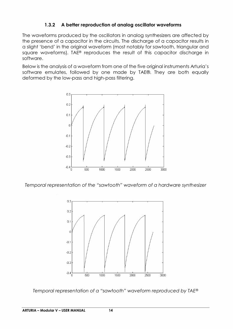
1.3.2 A better reproduction of analog oscillator waveforms
The waveforms produced by the oscillators in analog synthesizers are affected by
the presence of a capacitor in the circuits. The discharge of a capacitor results in
a slight ‘bend’ in the original waveform (most notably for sawtooth, triangular and
square waveforms). TAE® reproduces the result of this capacitor discharge in
software.
Below is the analysis of a waveform from one of the five original instruments Arturia’s
software emulates, followed by one made by TAE®. They are both equally
deformed by the low-pass and high-pass filtering.
Temporal representation of the “sawtooth” waveform of a hardware synthesizer
Temporal representation of a “sawtooth” waveform reproduced by TAE®
ARTURIA – Modular V – USER MANUAL 15
What’s more, the hardware analog oscillators were unstable. In fact, their
waveforms vary slightly from one period to another. If we add to this the fact that
the starting point for each period (in Trigger mode) can vary with the temperature
and other environmental conditions, we see why vintage synthesizers have such a
typical sound.
TAE® reproduces the instability of oscillators, resulting in a fatter and “bigger” sound.
1.3.3 Direct Filter Circuit Modeling
Due to advances in computer processing power, TAE® can now employ direct filter
modeling techniques to achieve unprecedented accuracy in the emulation of a
hardware synthesizer’s filter. By modeling the operation of the individual hardware
components of the filter circuit, the warm nuances synonymous with analog sounds
are recreated.
The following graph shows a single example of direct circuit modeling in action.
The peaks represent the generation of harmonics at multiples of the resonant
frequency when a particular filter is in self oscillation mode. These harmonics are
characteristic of hardware synthesizer filters and are due to the non-linear behavior
inherent to their analog circuitry. Anomalies such as these add to the richness and
warmth of the sound produced by the filter.
But you’ll notice there are two lines on the graph: Those are the superimposed
frequency domain plots for both one of Arturia's virtual instruments and the
hardware filter being emulated. They are practically indistinguishable, both on the
graph and to the human ear. The direct recreation of this analog circuitry causes
the same characteristics of the sound to be present, thus giving the user a truly
analog sound.

ARTURIA – Modular V – USER MANUAL 16
Comparison of harmonics generated by the filter circuits in self-oscillation
of TAE® and a hardware synthesizer
So here’s the bottom line: when you bring together a bunch of music lovers who
also have a deep understanding of the characteristics of electronic circuits, you
wind up with Arturia. And Arturia now offers you our most impressive software model
yet, the Modular V.
We take great satisfaction in knowing this great synthesizer will help you explore
previously unknown musical territory.

ARTURIA – Modular V – USER MANUAL 17
2 ACTIVATION AND FIRST START
2.1 Register and Activate
Modular V works on computers equipped with Windows 7 or later and Mac OS
X 10.8 or later. You can use the stand-alone version or use Modular V as an
Audio Units, AAX, VST2 or VST3 instrument.
Once Modular V has been installed, the next step is to register the software.
The registration process will require you to enter the serial number and the
unlock code you received with the product.
In order to proceed, go to this web page and follow the instructions:
http://www.arturia.com/register
Note: If you don’t have an Arturia account yet, you will need to create one.
The process is quick, but it does require that you can access your email address
during the registration process.
Once you have acquired an Arturia account you will be able to register the
product.
2.2 Initial setup
2.2.1 Audio and MIDI settings: Windows
At the top left of the Modular V application is a pull-down menu. It contains
various setup options. Initially you will need to go to the menu and choose the
Audio Settings option to get sound and MIDI flowing in and out.

ARTURIA – Modular V – USER MANUAL 18
Modular V main menu
You will then see the Audio MIDI settings window. This works in the same way
on both Windows and Mac OS X, although the names of the devices available
to you will depend on the hardware you are using.
Audio and MIDI settings window

ARTURIA – Modular V – USER MANUAL 19
Starting from the top you have the following options:
Device lets you choose which audio driver you want to use to route
sound out of the instrument. This might be your computer’s own driver
like Windows Audio, or an ASIO driver. The name of your hardware
interface may appear in this field.
Output Channels lets you select which of the available outputs will be
used to route audio out. If you only have two outputs, only two will
appear as options. If you have more than two you can select a specific
pair of outputs.
The Buffer Size menu lets you select the size of the audio buffer your
computer uses to calculate sound. A smaller buffer means lower latency
between pressing a key and hearing the note. A larger buffer means a
lower CPU load as the computer has more time to think, but can result
in a small latency. Find the optimum buffer size for your system. A fast,
modern computer should easily be able to operate at 256 or 128 sample
buffer size without creating pops or clicks in the sound. If you are getting
clicks, try raising the buffer a little. The latency is displayed on the right
hand side of this menu.
The Sample Rate menu lets you set the sample rate at which audio is
sent out of the instrument. The options here will depend on the capability
of your audio interface hardware though even most computers’ own
hardware can operate at up to 48kHz which is perfectly fine. Higher
sample rates use more CPU power so unless you have a good reason to
go up to 96kHz, then 44.1k or 48k is usually fine. The Show Control Panel
button will jump to the system control panel for whatever audio device
is selected.
Play Test Tone helps you to troubleshoot audio issues by confirming
whether sound can be heard through the correct device.
Your connected MIDI devices will appear in the MIDI Devices area. Click
the check box to accept MIDI from the device you want to use to trigger
the instrument. In standalone mode, Modular V listens for all MIDI
channels so there’s no need to specify a channel. You can specify more
than one MIDI device at once.
2.2.2 Audio and MIDI settings: Mac OS X
The process is very similar to initial setup for Windows and the menu is accessed
in the same way. The difference is that OS X uses CoreAudio to handle audio
routing and the audio device selection is made in the second dropdown
menu. Apart from that, the options work the same way as described in the
Windows section.

ARTURIA – Modular V – USER MANUAL 20
2.2.3 Using Modular V in plug-in mode
Modular V comes in VST, AU and AAX plug-in formats for use in all major DAW
software such as Cubase, Logic, Pro Tools and so on. You can load it as a plug-
in instrument and its interface and settings work the same way as in standalone
mode, with a couple of differences.
You can automate numerous parameters using your DAW’s automation
system.
You can use more than one instance of Modular V in a DAW project. In
standalone mode you can only use one at once.
You can route Modular V’s audio outputs more creatively inside your
DAW using the DAW’s own audio routing system.

ARTURIA – Modular V – USER MANUAL 21
3 USER INTERFACE
In this chapter we will give an overview of the features available to you with
Modular V. As with every Arturia product, we have gone to great lengths to
make the use of this software instrument as simple and as much fun as possible,
while also striving to make sure you never run out of new things to do with it as
your knowledge expands. After reading this chapter you should be ready to
delve as deeply into the workings of Modular V as you would like.
3.1 The virtual keyboard
The virtual keyboard lets you play a sound without connecting an external MIDI
device; just click a key to hear the active Voice. Drag the cursor across the
keys to hear a glissando.
The Modular V virtual keyboard
3.2 Toolbar
The toolbar that runs along the top edge of the instrument both in standalone
and plug-in mode provides access to many useful features. Let’s look at them
in detail. The first seven of these options can be found by clicking on the
Modular V section at the very top left hand corner of the instrument window.
3.2.1 Save Preset
The first option lets you save a preset. If you select this, you are presented with
a window where you can enter information about the preset. In addition to
naming it you can enter the author name, select a bank and type and select
some tags that describe the sound. This information can be read by the preset
browser and is useful for searching the preset banks later. You can also enter
freeform text comments in the Comments field, which is handy for providing a
more detailed description.
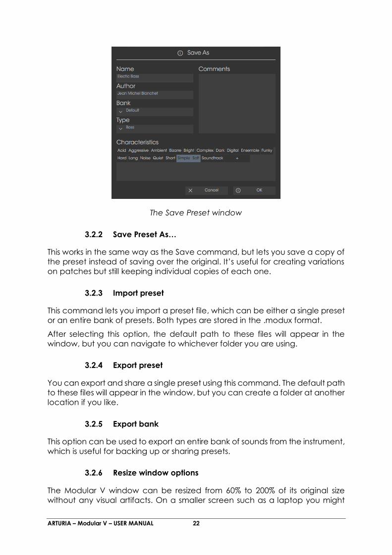
ARTURIA – Modular V – USER MANUAL 22
The Save Preset window
3.2.2 Save Preset As…
This works in the same way as the Save command, but lets you save a copy of
the preset instead of saving over the original. It’s useful for creating variations
on patches but still keeping individual copies of each one.
3.2.3 Import preset
This command lets you import a preset file, which can be either a single preset
or an entire bank of presets. Both types are stored in the .modux format.
After selecting this option, the default path to these files will appear in the
window, but you can navigate to whichever folder you are using.
3.2.4 Export preset
You can export and share a single preset using this command. The default path
to these files will appear in the window, but you can create a folder at another
location if you like.
3.2.5 Export bank
This option can be used to export an entire bank of sounds from the instrument,
which is useful for backing up or sharing presets.
3.2.6 Resize window options
The Modular V window can be resized from 60% to 200% of its original size
without any visual artifacts. On a smaller screen such as a laptop you might

ARTURIA – Modular V – USER MANUAL 23
want to reduce the interface size so it doesn’t dominate the display. On a
larger screen or a second monitor you can increase the size to get a better
view of the controls. The controls work the same at any zoom level but the
smaller ones can be harder to see at the smaller magnification values.
The Resize Window menu
3.2.7 Audio settings
Here you manage the way the instrument transmits sound and receives MIDI.
See section 2.2 of the manual for full details on this.
3.2.8 Preset browser overview
The Preset browser is invoked by clicking the toolbar button that has four
vertical lines. See section 3.3 of the manual for full details on this. The Filter,
name field and left / right arrows in the toolbar all assist with preset selection.

ARTURIA – Modular V – USER MANUAL 24
The Preset Browser
3.2.9 MIDI Learn assignment
The MIDI plug icon at the far right side of the toolbar places the instrument into
MIDI learn mode. Parameters that can be assigned to MIDI controls will be
shown in purple, and the idea is that you map physical buttons, knobs, faders
or pedals from hardware MIDI controllers to specific destinations inside the
instrument. A typical example might be to map a real expression pedal to the
virtual volume pedal, or buttons on a controller to the effect switches so you
can change the sound from your hardware keyboard.
ARTURIA – Modular V – USER MANUAL 25
MIDI Learn mode
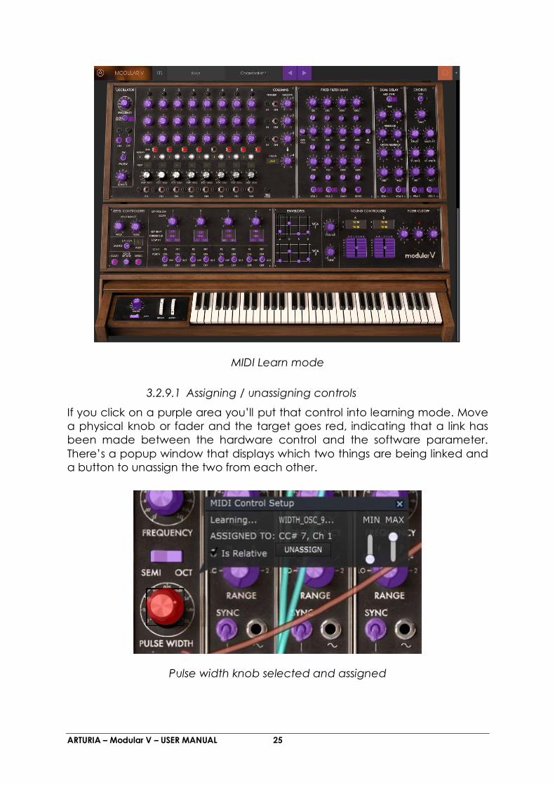
3.2.9.1 Assigning / unassigning controls
If you click on a purple area you’ll put that control into learning mode. Move
a physical knob or fader and the target goes red, indicating that a link has
been made between the hardware control and the software parameter.
There’s a popup window that displays which two things are being linked and
a button to unassign the two from each other.
Pulse width knob selected and assigned

ARTURIA – Modular V – USER MANUAL 26
3.2.9.2 Min / Max value sliders
There are also minimum and maximum value sliders that you can use to restrict
the parameter change range to something other than 0%-100%. For example,
you might want the filter cut-off be controllable via hardware from 30% to 90%.
If you made this setting (Min set to 0.30 and Max set to 0.90) your physical knob
would be unable to alter the volume lower than 30% or higher than 90%, no
matter how far you turned it. This is very useful for making sure you can’t
accidentally make the sound too quiet or too loud when performing.
In the case of switches which only have two positions (on or off), those would
normally be assigned to buttons on your controller. But it is possible to toggle
those with a fader or other control if you like.
3.2.9.3 Relative control option
The final option in this window is a button labelled “Is Relative”. It is optimized
for use with a specific type of control: one which sends only a few values to
indicate the direction and speed at which a knob is turning, as opposed to
sending a full range of values in a linear fashion (0-127, for example).
To be specific, a “relative” knob will send values 61-63 when turned in a
negative direction and values 65-67 when turned in a positive direction. The
turn speed determines the parameter response. Refer to the documentation
of your hardware controller to see if it has this capability. If so, be sure to switch
this parameter on when setting up its MIDI assignments.
When configured this way, movements of the physical control (usually a knob)
will change the software parameter by starting at its current setting, rather than
being an “absolute” control and snapping it to some other value as soon as
you start to move it.
This can be a great feature when controlling things like volume, filter, or effect
controls, since you won’t usually want them to jump massively out of their
current setting as soon as you start to modify them.
3.2.9.4 Reserved MIDI CC numbers
Certain MIDI Continuous Controller (MIDI CC) numbers are reserved and
cannot be reassigned to other controls. These are:
PitchBend
Ctrl Mod Wheel (CC #1)
After Touch
Ctrl Sustain On/Off (CC #64)
Ctrl All Notes Off (CC #123)
Ctrl Omni Mode Off (CC #124)
Ctrl Omni Mode On (CC #125)

ARTURIA – Modular V – USER MANUAL 27
Ctrl Poly Mode Off (CC #126)
Ctrl Poly Mode On (CC #127)
All other MIDI CC numbers may be used to control any assignable parameter
in Modular V.
3.2.10 MIDI controller configuration
There’s a small arrow at the far right hand side of the toolbar that deals with
MIDI controller configurations. This allows you to manage the different sets of
MIDI maps you may have set up for controlling the instrument’s parameters
from MIDI hardware. You can copy the current MIDI assignment setup or
delete it, import a configuration file or export the currently active one. This is a
quick way to set up different hardware MIDI keyboards or controllers with
Modular V without having to build all the assignments from scratch each time
you swap hardware.
3.2.11 The lower toolbar
3.2.11.1 Current control value
At the left hand side of the lower toolbar you will see a readout showing the
value or state of whatever control you are modifying. It will also display the
current value of a parameter without editing it: just hover the cursor over the
related control and the value will appear as pictured below.

ARTURIA – Modular V – USER MANUAL 28
3.2.11.2 Midi Channel Setting
At the right hand side of the lower toolbar are three small windows. The first
one on the left indicates the current MIDI Channel setting. Click on it and it will
expand to show the full range of values you can select (All, 1-16).
3.2.11.3 Panic button and CPU meter
The Panic button can be pressed to reset all MIDI signals in the event of stuck
notes or other issues. The Panic button is also MIDI-assignable.

ARTURIA – Modular V – USER MANUAL 29
The CPU meter is used to monitor how much of your computer’s CPU is being
used by the instrument.
3.3 The Preset Browser
The preset browser is how you search, load and manage sounds in Modular V.
It has a couple of different views but they all access the same banks of presets.
To access the search view, click on the browser button (the icon looks a bit like
books on a library shelf).
The Preset Browser button
3.3.1 Searching presets
The Search screen has a number of sections. By clicking on the Search field at
the top left you can quickly enter any search term to filter the preset list by
patch name. The Results column is updated to show the results of your search.
Press the X button in the search field to clear the search.
3.3.2 Using tags as a filter
You can also search using different tags. Clicking on a Type field shows only
presets that match that tag. The tag fields can be shown or hidden by using
the small down arrow buttons in their title fields. Results columns can be sorted
by clicking the same arrow button in their own section.

ARTURIA – Modular V – USER MANUAL 30
You can use multiple search fields to perform narrower searches. So by
entering a text search and also specifying type, bank and characteristics
options you could see only the presets that match those exact criteria.
Deselect any tag in any area to remove that criteria and widen the search
without having to go back and start again. Using “Ctrl + click” (Windows) or
“Cmd + click” (Mac) will allow you to select multiple elements in the same
area.
The second Results column can be switched to show Type, Sound Designer,
Favorite or Bank tags depending on how you like to search. Click on its options
menu button just next to its sort arrow.

ARTURIA – Modular V – USER MANUAL 31
3.3.3 The Preset Info section
The Info column on the right of the search field shows you information about
any preset. The information for User presets may be changed here: Name,
Type, Favorite, etc.
However, if you want to alter the information for a Factory preset you must first
use the Save As command to re-save it as a User preset. After this the Info
section will gain Edit and Delete buttons at the bottom of the window.
Click Edit and then make the desired changes, either by typing in one of the
fields or by using a pull-down menu to change the Bank or Type. You can even
add new Characteristics by clicking the + sign at the end of that list. Click Save
when you are done.
3.3.4 Preset selection: other methods
The pull-down menu to the right of the Search menu provides a different way
to select presets. The first option in this menu is called Filter, and it will display
the presets that fit the search terms you used in the Search field. So if you

ARTURIA – Modular V – USER MANUAL 32
searched for “Love” in the main search area, the results of that search will
appear here.
Similarly, if you previously selected a Type in the Search field you would see the
results of that search in this area instead.
Filter results may differ based on Search criteria
Selecting the All Types option in the pull-down menu will bypass the Search
criteria and show the entire list of presets.
The Categories below the line also ignore the Search criteria and display the
presets based on their Type.

ARTURIA – Modular V – USER MANUAL 33
3.3.4.1 Selecting a preset by its Type
Clicking on the name field in the center of the toolbar will show you a list of all
available presets. The list will also take into account any selections you have
made in the Search field. So if you have pre-selected a Characteristic such as
“Funky” this shortcut menu will only show you presets that match that tag.
The left and right arrows in the toolbar cycle up and down through the preset
list: either the full list, or the filtered list that resulted from the use of one or more
search terms.
3.3.5 Playlists
In the lower left corner of the Preset Browser window is a feature titled Playlists.
This is used to collect presets into different groups for different purposes, such
as a set list for a particular performance or a batch of presets related to a
particular studio project.
3.3.5.1 Add a playlist
To create a playlist, click the plus sign at the bottom:
Give the playlist a name and it will appear in the Playlists menu. You can
rename the playlist at any time; just click the pencil icon at the end of its row.
ARTURIA – Modular V – USER MANUAL 34
3.3.5.2 Add a preset
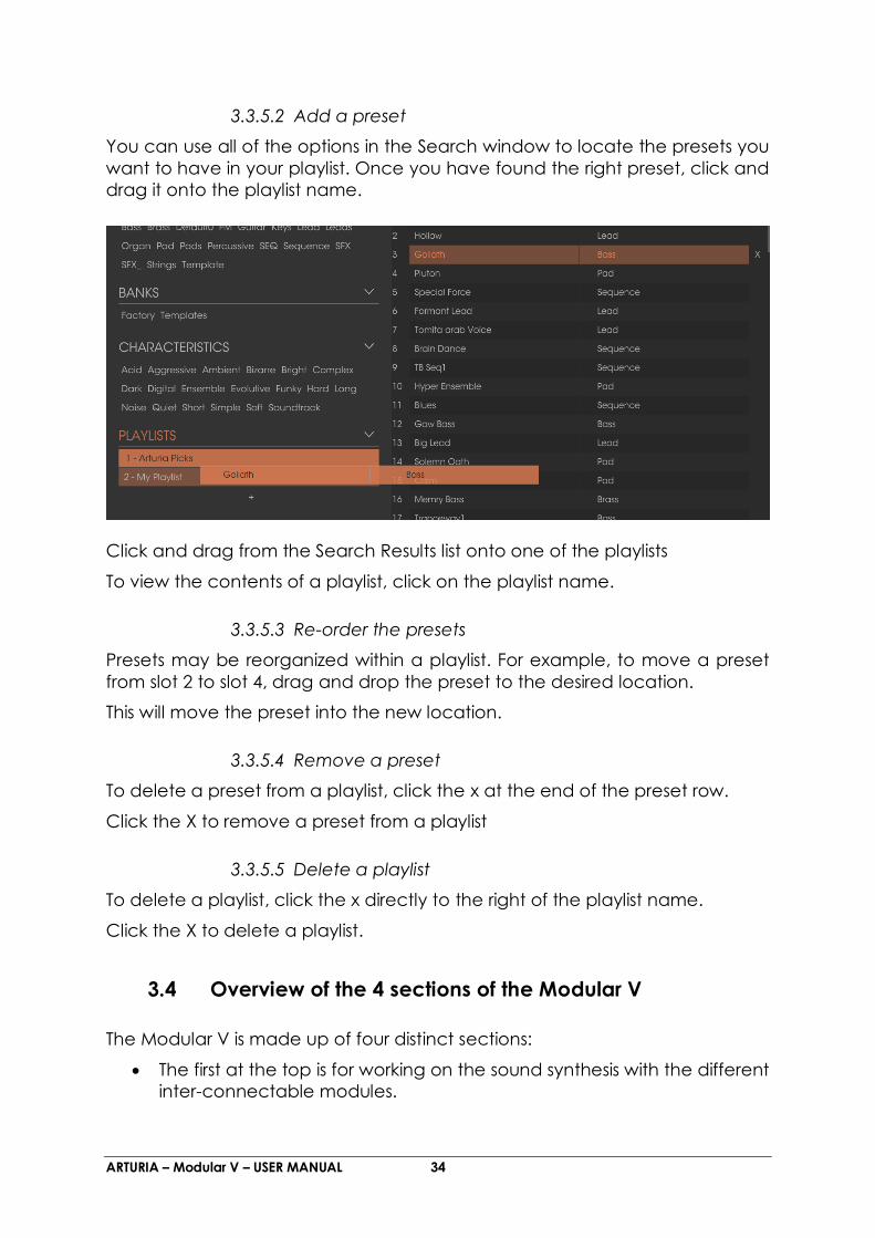
You can use all of the options in the Search window to locate the presets you
want to have in your playlist. Once you have found the right preset, click and
drag it onto the playlist name.
Click and drag from the Search Results list onto one of the playlists
To view the contents of a playlist, click on the playlist name.
3.3.5.3 Re-order the presets
Presets may be reorganized within a playlist. For example, to move a preset
from slot 2 to slot 4, drag and drop the preset to the desired location.
This will move the preset into the new location.
3.3.5.4 Remove a preset
To delete a preset from a playlist, click the x at the end of the preset row.
Click the X to remove a preset from a playlist
3.3.5.5 Delete a playlist
To delete a playlist, click the x directly to the right of the playlist name.
Click the X to delete a playlist.
3.4 Overview of the 4 sections of the Modular V
The Modular V is made up of four distinct sections:
The first at the top is for working on the sound synthesis with the different
inter-connectable modules.

ARTURIA – Modular V – USER MANUAL 35
The second, underneath, is an extension allowing us to regroup the
different external input-outputs and some internal cables.
The third holds a sequencer and a certain number of effects.
The fourth holds the virtual keyboard, as well as a section dedicated to
the key follows. and essential controllers.
It is possible to keep only the fourth section on the screen, by clicking on the
Keyb icon on the toolbar.
3.4.1 The synthesis section
Visible as soon as the synthesizer is opened, it is made up of two parts
(cabinets). It integrates the 33 modules necessary for the creation of sounds.
The modules in the upper part can be exchanged via the menu that appears
when their name has been clicked. It is thus possible to replace an envelope
with a ring modulator, a filter with a frequency translator.
The first section composed of 2 cabinets
3.4.2 The other three sections
The first, situated at the top of the synthesizer, contains the step sequencer and
4 effects (the right hand effect can be either a chorus or phaser). The two
others are found under the synthesis section. One is a small extension

ARTURIA – Modular V – USER MANUAL 36
containing the internal cables, while the other holds the virtual keyboard and
its assignable controllers.
The third section composed of a sequencer and effects
The virtual keyboard and related controllers
The extensions section
3.5 Modular synthesizer
The modular synthesizer cabinet contains 28 modules, which will help you to
create an infinite variety of sounds. These 28 modules can be broken down
into different categories and will be connected by cables.

ARTURIA – Modular V – USER MANUAL 37
Modular synthesizer
3.5.1 Description of the synthesis section modules
3.5.1.1 The oscillators
They are 9 in total, regrouped in threes like the original modular system:
1 “Driver” oscillator: allow the management of the frequency and impulse
width of the 3 “slave” oscillators. These 3 “slave” oscillators can be tuned and
modulated separately. They deliver 4 waveforms that can be simultaneously
used.
An oscillator bank: 1 “driver” and 3 “slave oscillators”

ARTURIA – Modular V – USER MANUAL 38
3.5.1.2 The white and pink noise generator
To the oscillators previously described we add a white or pink noise generator.
It is accessible in the form of 4 outputs. This mode also has two 6 dB/oct. filters:
a low-pass (LPF) and a high-pass (HPF). With these, you can, for example,
change the nature of the noise to make it more or less brilliant.
White and pink noise generator
3.5.1.3 The filters
The Modular V possesses 3 filters. Each of these filters can be chosen between
4 types:
Low pass 24 dB/octave (type 904A)
High pass 24 dB/octave (type 904B)
Band pass and band reject 24 dB/octave (type 904C)
Multi-modes 12 dB/octave (low-pass, high-pass, band pass, band reject,
bell, shelf).
The type change is done by clicking on the title of the filter type and by
selecting the desired filter in the proposed menu.

ARTURIA – Modular V – USER MANUAL 39
The 4 filter types
3.5.1.4 The auxiliary ADSR modulation envelopes
They are 6 in total, allowing the evolution of the sound in time.
The auxiliary envelope
3.5.1.5 The dual trigger delay
A module with two trigger delays allows the management of the signals used
to trigger envelopes and sequencer.

ARTURIA – Modular V – USER MANUAL 40
The trigger delays
3.5.1.6 The LFOs
Two low frequency oscillator modules (“Low Frequency Oscillator”) are used to
create a cyclic modulation on one (or several) sound setting.
The “slave” oscillators can also be used as LFOs when they are brought to
low frequency positions when they are switched in low frequencies (“low
freq”). This gives a total availability of 11 LFO modules.
The LFO module
ARTURIA – Modular V – USER MANUAL 41
3.5.1.7 The VCAs
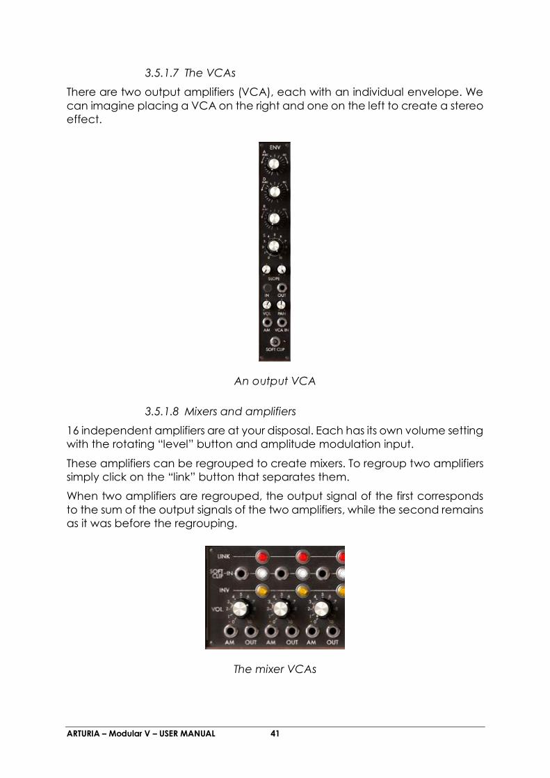
There are two output amplifiers (VCA), each with an individual envelope. We
can imagine placing a VCA on the right and one on the left to create a stereo
effect.
An output VCA
3.5.1.8 Mixers and amplifiers
16 independent amplifiers are at your disposal. Each has its own volume setting
with the rotating “level” button and amplitude modulation input.
These amplifiers can be regrouped to create mixers. To regroup two amplifiers
simply click on the “link” button that separates them.
When two amplifiers are regrouped, the output signal of the first corresponds
to the sum of the output signals of the two amplifiers, while the second remains
as it was before the regrouping.
The mixer VCAs

ARTURIA – Modular V – USER MANUAL 42
3.6 The other sections
3.6.1 The sequencer
This module conforms to the original model while simplifying the programming
with internal connections.
It is with this module that you can create melodic sequences or sequences
applied to a parameter (a sequence line applied to the opening of the
frequency can, for example, be very efficient).
The sequencer has 3 sections:
Low frequency oscillator controls the timing of passage from one sequence to
another. Its speed can be set statically with the “frequency” button and
dynamically with the modulation input on the first page. Two buttons, “on” and
“off” respectively start and stop this generator.
Eight-step sequence manager. Each step defines 3 levels of output
modulations, using 3 knobs. The manager moves from one step to another on
each pulse from the low frequency generator. The 3 rows of sequence can
also be chained to create a longer sequence (up to 24 steps)
The output controller allows the management of the 4 modulation outputs for
the current step. The first 3 outputs take their values from the rotating buttons
of the current step (on the corresponding line), eventually with a configurable
smoothing through the “smooth” buttons. The fourth output, for which the
smoothing can also be set through the “smooth” button, is managed in the
following manner. It takes the value from one of the 3 outputs in function with
the current step and the type of progression specified with the “Chain”
selector: This allows the linking sequences to create variations. For example to
link lines 1, 2 and 3 to obtain a 24 step on the same controller.

ARTURIA – Modular V – USER MANUAL 43
The sequencer sections
3.6.2 The effects
The second section also has three effects, which will allow you to bring more
color and space to your sound or sequence.
These are on the right of the sequencer; the chorus can be replaced by a
phaser.
The 3 effect modules
ARTURIA – Modular V – USER MANUAL 44
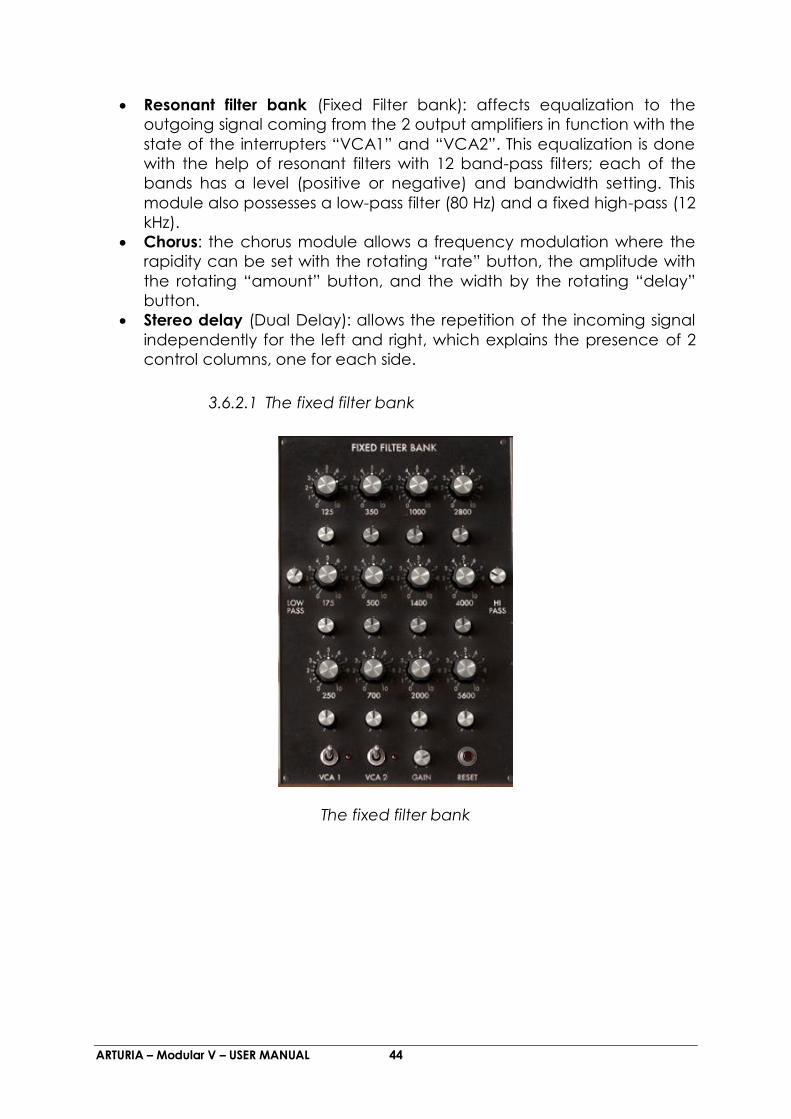
Resonant filter bank (Fixed Filter bank): affects equalization to the
outgoing signal coming from the 2 output amplifiers in function with the
state of the interrupters “VCA1” and “VCA2”. This equalization is done
with the help of resonant filters with 12 band-pass filters; each of the
bands has a level (positive or negative) and bandwidth setting. This
module also possesses a low-pass filter (80 Hz) and a fixed high-pass (12
kHz).
Chorus: the chorus module allows a frequency modulation where the
rapidity can be set with the rotating “rate” button, the amplitude with
the rotating “amount” button, and the width by the rotating “delay”
button.
Stereo delay (Dual Delay): allows the repetition of the incoming signal
independently for the left and right, which explains the presence of 2
control columns, one for each side.
3.6.2.1 The fixed filter bank
The fixed filter bank

ARTURIA – Modular V – USER MANUAL 45
3.6.2.2 The “Dual delay”
You can also enrich your sound and give it more stereo space; for this, add
stereo delay.
The delay effect
As is the case for all of the Modular V effects, the Dual Delay works in “real”
stereo in the sense that it possesses an independent input and output for both
sides.
It is also possible to keep a part of the sound effect free by deactivating one
of the two VCA switches. This can be very interesting when using the synthesizer
for multiple tones (for example, a bass sound played on the keyboard coming
out to the VCA1 which is set without effect and an arpeggio sound played by
the sequencer which will be directed to the VCA2 where the effects will be
activated)

ARTURIA – Modular V – USER MANUAL 46
3.6.2.3 The chorus
Chorus is used to create a doubling effect on a sound; this will give it more
width and “thickness”. If you accentuate the effect intensity, you will obtain a
very discordant sound.
The chorus effect
With chorus, it is also possible to obtain the stereo sweeping of the sound by
decreasing the “amount” knob and working only on the value of the “stereo
width” (depth) and “stereo rate” (oscillation speed) knobs. This will create an
“auto pan” effect. The effect will be even more present if you lower the level
of the signal without effect (“Dry”), leaving only the effect return (“wet”).
3.6.3 The keyboard controllers
The different settings concerning the real time controllers affected to the
keyboard can be found on the left, above the virtual keyboard.
Here you will find all of the settings applied to the 4 key followers, the pitch
bend and modulation wheels, as well as velocity and aftertouch.
The controller connection jacks
ARTURIA – Modular V – USER MANUAL 47
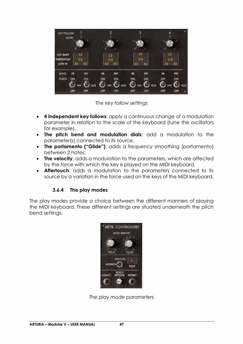
The key follow settings
4 independent key follows: apply a continuous change of a modulation
parameter in relation to the scale of the keyboard (tune the oscillators
for example).
The pitch bend and modulation dials: add a modulation to the
parameter(s) connected to its source.
The portamento (“Glide”): adds a frequency smoothing (portamento)
between 2 notes.
The velocity: adds a modulation to the parameters, which are affected
by the force with which the key is played on the MIDI keyboard.
Aftertouch: adds a modulation to the parameters connected to its
source by a variation in the force used on the keys of the MIDI keyboard.
3.6.4 The play modes
The play modes provide a choice between the different manners of playing
the MIDI keyboard. These different settings are situated underneath the pitch
bend settings.
The play mode parameters

ARTURIA – Modular V – USER MANUAL 48
The “mono/unison/poly” switch lets you choose: a monophonic playing mode
(a single note played at a time, chords cannot be produced in this mode. This
mode corresponds to the mode used in the original Modular), a polyphonic
mode (several notes can be played at the same time to form a chord). The
maximum number of voices is displayed in the corresponding window. The
unison mode is identical to the monophonic, but there are as many voices
played at the same time as the polyphonic voices.
The “legato” button, active when the synthesizer is in monophonic mode,
allows the activation of the portamento – or “glide” in English – freely on all of
the notes when it is active. If you wish to only use portamento on notes that are
linked, deactivate the legato mode.
The “retrig” button, also active when the synthesizer is in monophonic mode,
allows the systematic re-triggering of the envelopes, even if you link the notes
in your playing sequence. If, on the other hand, you don’t wish to re-trigger the
envelopes when 2 notes are linked, leave the button raised.
When the synthesizer is in polyphonic mode, 1 LCD display on the right of the
switch allows the setting of the maximum number of notes that can be played
simultaneously (“poly” screen. This setting can limit the CPU load provoked by
each simultaneous note played on your MIDI keyboard or sequencer.
To activate the portamento mode, click on the “ON” button under the
portamento intensity knob (“glide”), situated next to the 2 dials, on the right of
the virtual keyboard.
The portamento settings
3.6.5 The sound design controllers
Three control surfaces allow the modulation of the sound parameters in a fast
and intuitive manner:
Eight sliders that allow control of the envelopes of the output VCA 1 and
2
Two 2D controllers that can be assigned to the parameters of your
choice
Three knobs for the setting of cut-off frequency off the 3 filters.

ARTURIA – Modular V – USER MANUAL 49
3.6.5.1 The envelope control sliders
The two envelopes are directly linked to those of the VCAs: if you modify one
of the parameters (Attack, Decay, Sustain or Release – the 2 slope parameters
are not represented here for simplicity), the modification will automatically and
identically be taken to the synthesizer. The opposite is also true.
3.6.5.2 The 2D Pads
These 2 XY pads can be assigned to any destination using the four output
connections present in the real-time controller connection module as shown
below.
The connection of modulation inputs of filter1 to the 2D controller
Using the 2D controller

ARTURIA – Modular V – USER MANUAL 50
To have access to these 2 modulation inputs on a low-pass resonant, it is
essential to change the filter type (the low-pass 24dB does not possess a
modulation input in the resonance.) Take the multimode filter and set it to low-
pass mode, if it isn’t already the case.
3.6.5.3 The filter cutoff frequency controller
On the right of the 2D Pads you will find controls for the cutoff of the 3 filters
modules.
These will only be active if the filters are used in the current sound (a diode
above each knob indicates if it is active).
Simply try to change the settings and you will immediately hear the result on
your sound.
The three filter cutoff frequency controllers
This chapter has given you a look at some of the many aspects of the Modular
V. Now try to go a little deeper using the rest of the documentation. You will
find all of the details concerning the modules, the sequencer and the many
different modes of use of the Modular V.

ARTURIA – Modular V – USER MANUAL 51
4 The modules in details
The Modular V can be broken down into 4 parts, from top to bottom, a section
containing sequencer and effects, a section dedicated to the sound
programming, a small extension where the external cables are regrouped
(velocity, after-touch, external signals...) and finally a section containing the
keyboard and different play settings.
4.1 Programming section
4.1.1 Description
The programming section gathers all of the modules, which need to be
connected by cables. It is on this screen that the different connections (Patch)
needed for the programming of the sound will be made.
It is sometimes necessary to connect a module in the programming section to
a module in the sequencer section. To simplify connections between the 2
screens, the inputs and outputs of the sequencer section are grouped on a
small extension under the sound programming section.
The sound programming section contains:
Nine oscillators, grouped in threes, which can also be used as
modulation source.
Two low frequency oscillators dedicated to modulations.
Three filters.
Six envelopes dedicated to modulations.
Two envelopes dedicated to output amplifiers.
A dual trigger delay.
A noise generator and the associated filters.
1 ring modulator
4 envelope followers
2 sample and holds
1 frequency translators
1 formant filter
A set of amplifiers, which can be grouped to form mixers.
The number of spaces at the upper part of the section being inferior to the
number of modules, the choice is made through a menu. It is thus possible to
organize them at your convenience.
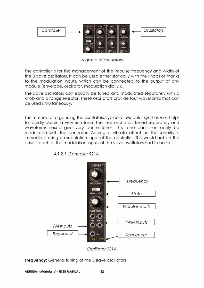
4.1.2 Oscillators
The oscillators, nine in total are regrouped in threes. Each group has a 921A
type controller and three 921B type slave oscillators.
ARTURIA – Modular V – USER MANUAL 52
A group of oscillators
The controller is for the management of the impulse frequency and width of
the 3 slave oscillators. It can be used either statically with the knobs or thanks
to the modulation inputs, which can be connected to the output of any
module (envelope, oscillator, modulation dial…).
The slave oscillators can equally be tuned and modulated separately with a
knob and a range selector. These oscillators provide four waveforms that can
be used simultaneously.
This method of organizing the oscillators, typical of Modular synthesizers, helps
to rapidly obtain a very rich tone. The tree oscillators tuned separately and
waveforms mixed give very dense tones. This tone can then easily be
modulated with the controller. Adding a vibrato effect on this sonority is
immediate using a modulation input of the controller. This would not be the
case if each of the modulation inputs of the slave oscillators had to be set.
4.1.2.1 Controller 921A
Oscillator 921A
Frequency: General tuning of the 3 slave oscillators
Controller Oscillators
Frequency
State
Impulse width
PWM Inputs FM Inputs
Sequencer
choice
Keyboard
follow

ARTURIA – Modular V – USER MANUAL 53
State: General tuning mode choice (by 1/2 tone, by octave)
Impulse width: Signal impulse width “Sawtooth”, “Square”, “Triangle”
FM Inputs: Frequency modulation input connection jacks
WPM Inputs: Pulse width modulation connection jacks
Keyboard follow: Keyboard follows choice tuning the master oscillator (off, no,
follow 1, 2, 3 or 4).
Sequencer Choice: Choice of the sequencer output tuning the master
oscillator (no sequencer, sequencer 1, 2, 3 or 4).
The general tuning of the 3 slave oscillators is done with the “Frequency” knob.
Depending on the position of the “State” interrupter, the range of the knob is
+/- an octave by semitone or +/- six octaves par fifth and quarter.
The impulse width affected to the “sawtooth”, “triangle” and “square” signals
of the 3 slave oscillators is modified with the “Width” knob.
Three frequency modulation inputs and 2 impulse width modulation inputs
allow the control of these parameters thanks to the outputs of the other
modules.
When one of these inputs is connected, a click on the Jack will modify the
amplitude of the modulation. The Jack knob functions like a rotating dial where
the position for inactivity (no modulation) is at the center. The modulation can
thus be positive (button turned to the right) or negative (button turned to the
left).
The first two frequency modulation inputs work in an exponential mode,
while the third, “Lin” works in a linear mode.
Connected directly to a generator (envelope, oscillator, sequencer…), the
maximum amplitude of the modulation is of +/- 4 octaves. When it is necessary
to have a stronger modulation, an amplifier module must amplify the signal of
the generator.
A certain number of internal connections simplify the use of the keyboard
follow, sequencer, portamento and pitch bend.
To avoid having to manage the tuning of the keyboard follow with the
amplitude of the modulation input, with a visualizer we can choose which
keyboard follow (from 1 to 4) is to be used. This keyboard follow is directly
configured to tune the oscillator in function to the note played.
The functioning is the same for the sequencer outputs (1 to 4) controlling the
tuning of this group of oscillators. In the “no” follow position, the oscillator is set
to the note C3, irrespective of the keyboard notes. In the same manner, when
set to the “no” sequencer position, this group of oscillators is disconnected from
the sequencer output.

ARTURIA – Modular V – USER MANUAL 54
A keyboard follow can of course be connected to modulation input. In that
way, the pitch of each notes can be adjust very fine. We can then simulate
the non-linearity of analog keyboard.
The “LFO” position of the display indicates that the oscillator group is no longer
dependant of the keyboard. That is to say, it permanently functions on a
monophonic voice. This function is especially useful when we want to use this
oscillator group as source of low frequency modulation.
Furthermore, each of the keyboard follows can activate the response of
oscillators and filters to portamento and pitch bend.
4.1.2.2 Slave oscillator 921B
Oscillator 921B
Frequency: Sets the frequency of the oscillator. By left click, setting by semi-
tone, by right click fine setting.
Range: Setting of the oscillator range. (low, 32, 16, 8, 4, 2)
Synchronization: Synchronization interrupter Soft/Hard
Synchro input: Menu to select the synchronization oscillator
FM Inputs: Frequency modulation input connection jacks
Outputs: Connection jacks for the four oscillator outputs
The 921B type slave oscillators possess four outputs that can be used
simultaneously: sawtooth, sinusoid, triangle, square.
There is also an output generating a trigger signal synchronous with the square
signal and with an identical width, which lets us trigger envelopes and
Frequency
Range
Synchronization
Synchro input
FM Inputs
Audio outputs of
the 4 wave forms

ARTURIA – Modular V – USER MANUAL 55
sequencer in a cyclic manner. This output is visible only visible at trigger input
menu level.
Sawtooth Square
Triangle Sinusoid
These oscillators are independently tuned with the “frequency” knob. This
button possesses a coarse +/- an octave per semi-tone setting with a left click
and a fine tune setting +/- a semi-tone with a right click.
The “range” selector allows the setting of oscillator range on 6 positions: Low,
32, 16, 8, 4 and 2. With the Low position the oscillator can be used at a very low
frequency (on a cycle of more than 6 minutes). The other positions set the
oscillator to octaves 1,2,3,4 and 5. That is to say the note C3 is played
respectively on C1, C2, C3, C4 and C5.
At the Low position the oscillators perform modulations using lower
calculation power than the other positions.
Two modulation inputs allow the separate setting of each of the oscillators in
the group. They are very useful for modifying the tuning between oscillators
thanks to a low frequency oscillator, a keyboard follow or other modulation
source.
Like the controller modulation inputs, they can be connected to the output of
another module. Connected to an oscillator functioning in the same audible
spectrum, they can obtain sonorities with FM characteristics.
A synchronization input and the associated interrupter allow the
synchronization of the slave oscillator on one of the other oscillators. In this

ARTURIA – Modular V – USER MANUAL 56
case, the synchronizing oscillator will be heard while the synchronized oscillator
will improve the tone.
In the low position, the synchronization is said to be “hard”, which is to say that
the synchronized oscillator will restart a cycle for every cycle on the
synchronizing oscillator.
In the high position, the synchronization is said to be “soft”, and in this case, the
synchronized oscillator will only restart its cycle if it is coming to the end of the
cycle when the synchronizing oscillator begins its cycle.
A connected oscillator is active and consumes calculation power. It is
therefore necessary to verify that the connected oscillators are in use. Similarly,
a group of oscillators disconnected from the keyboard by the “keyb”
interrupter is permanently active.
4.1.3 Filters
The Modular V possesses 3 filter modules. It is possible to choose one of four
types of filter for each of the modules: a low-pass 24 dB/octave (type 904A), a
high-pass 24dB/octave (type 904B), a band-cut and band-pass 24 dB/octave
(type 904C) and finally a multi-mode 12 dB/octave filter. Clicking on the name
of the module and selecting the filter from the menu proposed does the type
change.
All of these filters possess internal connections to simplify the use of keyboard
follows, portamento, pitch bend and sequencer.
To avoid having to manage the tuning of the keyboard follow with the
amplitude of the modulation input, with a display we can choose if a keyboard
follow is to be used and which one. This keyboard follow is done to get a
correct pitch from the keyboard. Depending on the configuration of the
chosen keyboard follow, the portamento and the pitch bend will be applied
or not to this filter.
The functioning is the same for the sequencer outputs (1 to 4) controlling the
tuning of the cut-off frequency of this filter. In the “no” follow position, the filter
is independent of the notes played on the keyboard. In the same manner, set
to the “no” sequencer position, the filter is disconnected from the sequencer
output.
It is still possible to connect a keyboard follow or a sequencer output to a
modulation input obtaining a tuning as fine as necessary.

ARTURIA – Modular V – USER MANUAL 57
4.1.3.1 Low pass 24 dB/octave filter (904A)
Low pass filter
Frequency: Sets the filter cut-off frequency
Resonance: Sets the filter resonance
Audio Output: Filter output connection jack
Audio Input: Filter input connection jack
Modulation inputs: Frequency modulation input connection jacks
Keyboard follow: Keyboard follow choice tuning the filter (no follow, follow 1,
2, 3 or 4).
Sequencer choice: Choice of the sequencer output tuning the filter (no
sequencer, sequencer 1, 2, 3 or 4).
The low-pass 24 dB/octave filter is typical of Bob Moog’s synthesizers. It has a
setting for the cut-off frequency and a setting for the resonance. Only
connecting the output of any module to one of the 3 modulation inputs can
dynamically modulate the cut-off frequency.
Like all of the modulation inputs, once connected, turning the dial of the jack
with a right click sets its amplitude. Receiving a modulation directly from the
output of a generator (envelope, oscillator, and sequencer), the maximum
modulation amplitude is of +/- 9 octaves. When it is necessary to have a
stronger modulation, an amplifier module must amplify the signal of the
generator.
The following image represents the spectrum of a low-pass resonant filter with
a cut-off resonance of 500 Hz.
Frequency
Resonance
Audio Output
Audio Input
Modulation inputs
Sequencer
choice
Keyboard follow

ARTURIA – Modular V – USER MANUAL 58
Low-pass 24 dB/octave filter
4.1.3.2 High-pass 24 dB/octave filter (904B)
High-pass filter
Frequency: Sets the filter cut-off frequency
Audio Output: Filter output connection jack
Audio Input: Filter input connection jack
Modulation inputs: Frequency modulation input connection jacks
Keyboard Follow: Keyboard follow choice tuning the filter (no follow, follow
1,2,3 or 4).
Sequencer Choice: Choice of the sequencer output tuning the filter (no
sequencer, sequencer 1, 2, 3 or 4).
Unlike the low-pass 904A filter, the high-pass 904B filter does not possess
resonance. The cut-off frequency can be set with the rotating “frequency” dial
or by the 3 modulation inputs which function in the same manner as the inputs
of the low-pass.
Frequency
Audio Output Audio Input
Modulation
inputs

ARTURIA – Modular V – USER MANUAL 59
The following image represents the spectrum of a high-pass filter with a cut-off
frequency of 500 Hz.
High-pass 24 dB/octave filter
4.1.3.3 Band-pass 24 dB/octave filter (904C)
Band-pass filter
Frequency: Sets the filter cut-off frequency
Resonance: Sets the bandwidth of the filter
Type: Choice of filter type (band reject or band pass)
Audio Output: Filter output connection jack
Audio Input: Filter input connection jack
FM Inputs: Frequency modulation input jacks
Mod. Width input: Bandwidth modulation input connection jack
Keyboard follow: Keyboard follows choice tuning the filter (no follow, follow 1,
2, 3 or 4).
Frequency Resonance
Type
Audio Output Audio Input
FM Inputs Mod. Width input

ARTURIA – Modular V – USER MANUAL 60
Sequencer Choice: Choice of the sequencer output tuning the filter (no
sequencer, sequencer 1, 2, 3 or 4).
The 24dB band pass filter resembles the 904C filter, but the difference from it is
that while the 904C is a pairing of the 2 associated low-pass and high-pass
filters, this one is independent of the 2 other filters. The central frequency can
be set with the rotating “Frequency” button, the bandwidth, of 1/3 octave to
3 octaves with the “Resonance” knob. The first modulation input allows the
dynamic modification of the bandwidth, the 2 others, the central frequency.
A “type” selector provides a choice of filtering, band pass or band reject.
The following images represent the spectrum of the band-pass and band-
reject filters where the central frequency is 500 Hz.
Band-pass 24 dB/octave filter Band reject 24 dB/octave filter
4.1.3.4 Multi-mode 12 dB/octave filter
Multimode 12 dB/octave filter
Type: Choice of filter type
Type
Frequency Resonance
Gain
Audio Output
FM Inputs
Audio Input
ModRes Input

ARTURIA – Modular V – USER MANUAL 61
Frequency: Sets the filter cut-off frequency
Resonance: Sets the resonance of the filter
Gain: Sets the gain for bell, shelf High and Low.
Audio Output: Filter output connection jack
Audio Input: Filter input connection jack
FM Inputs: Frequency modulation input jacks
ModRes Input: Resonance modulation input connection jack
Keyboard follow: Keyboard follow choice tuning the filter (no follow, follow 1,
2, 3 or 4).
Sequencer Choice: Choice of the sequencer output tuning the filter (no
sequencer, sequencer 1, 2, 3 or 4).
The multi-mode 12 dB/octave filter has different types of filtering that the
original Modular synthesizers could not offer. The selector holds six types if
filtering: low-pass, band-pass, notch, high-pass, low-shelf, high-shelf, bell.
The 3 knobs “Frequency”, “Resonance”, and “Gain” respectively set the cut-
off frequency, the resonance, and the gain (used only for the shelf and bell)
Three modulation inputs allow the dynamic modification of the cut-off
frequency.
The following images represent the different spectrum of the different filters,
the cut-off frequency is constant at 500 Hz.
Low-pass 12 dB/octave High-pass 12 dB/octave
Notch 12 dB/octave Bell 12 dB/octave

ARTURIA – Modular V – USER MANUAL 62
Low-shelf 12 dB/octave High-shelf 12 dB/octave
4.1.4 Modulation envelopes
Envelope
Attack: Sets the attack time (Attack)
Decay: Sets the decay time
Release: Sets the release time
Sustain: Sets the sustain level
Input Trigg: Trigger signal input connection
Output: Envelope output signal
Six in total, the modulation envelopes make the sonority evolve in function with
time. An envelope possesses four sequentially following temporal periods:
attack, decay, sustain and release. When the input trigger goes from an
inactive to an active state, the envelope launches its sequences “attack”
followed by “decay” and remains in the “sustain” state as long as the input
trigger remains active. When it goes to an inactive state, the envelope begins
Attack (A)
Decay (D)
Release (R)
Sustain (S)
Input Trigg Output

ARTURIA – Modular V – USER MANUAL 63
the “release” sequence. If the input trigger becomes inactive before the first 2
sequences have finished, the envelope goes directly to the “release” phase.
The input trigger can be connected to the output trigger coming from the
keyboard, the trigger delay module, the oscillators trigger output, or from the
sequencer.
The time of the different periods are controlled by the “Attack”, “Decay” and
“Release” knobs. The “Sustain” knob is to set the level of the envelope output
during the sustain period.
t
D
S
A
R
Trigg On
Representation of the envelope

ARTURIA – Modular V – USER MANUAL 64
4.1.5 Output amplifiers (VCA)
Output envelope
Attack: Sets the attack time
Decay: Sets the decay time
Release: Sets the release time (release)
Sustain: Sets the sustain level
Slope Time: Sets the intermediate decay time
Slope Level: Sets the intermediate decay level
Input Trigg: Input trigger signal connection jack
Envelope out: Envelope out connection jack
Audio Input: VCA input connection jack
Panoramic: Sets the position in stereo space
Soft Clip: Use of gentle saturation
AM Input: Audio modulation Input jack
Attack
Decay
Release
Sustain
Slope Level Slope Time
Audio Input AM Input
Gain
Input Trigg
Panoramic
Mod Output
Soft Clip

ARTURIA – Modular V – USER MANUAL 65
There are 2 output amplifiers, each possessing its own envelope. These
amplifiers are internally linked to a panoramic manager, which allows, through
the “panoramic” knob, to position the output in stereo space.
These amplifiers are the last step in the generation of a sound. The associated
envelope sculpts the temporal form of the signal at the end of the sequence
after the application of all of the other modulations. Unlike the modulation
envelopes, it has an extra period between the “attack” and “decay”
sequences, called “slope”. The time and level can be set for this period and
allows the envelope to move from the high point after attack to slope before
moving to the decay:
t
D
S
A
R
Sn
St
t On Trigg
Representation of the output VCA envelope
The output amplifier internally connected to this envelope has volume “gain”
and amplitude input modulation settings.
The input trigger can be connected to the output trigger coming from the
keyboard, the trigger delay module, the oscillators or LFO trigger output, or
from the sequencer.
Each of the two amplifiers possesses a trigger output, which is activated when
the signal level is cancelled. This output can be very useful for stopping the
sequencer for example.
A jack allows the connection of the output of the associated envelope to other
modulation inputs.
A button applies the simulation of the current regulation present in the original
amplifiers (soft clipping).
Soft saturation is heavy on CPU calculation.

ARTURIA – Modular V – USER MANUAL 66
4.1.6 Low frequency oscillators (LFO)
Low frequency oscillator
Frequency: Sets the oscillation frequency
Delay: Delay time setting after a keyboard trigger
Mode: Choice of frequency setting: low, mid, synchronized on the MIDI tempo
Fade in: Sets the time constant for the increase of modulation
Width: Sets the impulse width
PWM Input: Input connection for the impulse width modulation
FM Input: Frequency modulation input connection
Outputs: Connection jacks for the different outputs
The use of a low frequency generator as a modulation source is typical. It
allows the gentle evolution of the tone of a sound or to simulate vibrato and
tremolo.
Even though the oscillators can be used at very low frequencies, there are 2
modules specifically for this purpose, which allow the oscillators to be kept for
use in the audible domain.
These oscillators possess five outputs that can be used simultaneously:
sawtooth, sinusoid, triangle, square, random.
The oscillation frequency can be statically set with the rotating “frequency”
button dynamically with the associated modulation input. The impulse width
can also be statically set with the “width” button and by its modulation input.
Frequency
Delay
Fade in
Width
PWM Input
FM Input
Outputs
Mode

ARTURIA – Modular V – USER MANUAL 67
The “mode” interrupter synchronizes the oscillation frequency with the tempo
of the host sequencer. In this mode, the rotating button chooses a frequency
depending on the application’s tempo (multiple or sub multiple).
Two other buttons are affecting a delay and a fade in at the output of this
generator. Initialized on a keyboard trigger, the generator output will only
begin to oscillate when the internal counter reaches a time value set with the
“delay” knob. This oscillation wills gently increase following the time constant
set with the rotating “fade in”.
There is also an output generating a trigger signal synchronous with the square
signal and with an identical width, which lets us trigger envelopes and
sequencer in a cyclic manner. This output is visible only visible at trigger input
menu level.
4.1.7 Controlled amplifiers / Mixers
Controlled amplifier (VCA)
Audio Input: Amplifier input connection jack
Audio Output: Amplifier output connection jack
AM Input: Amplitude modulation input connection jack
Volume: Input gain setting
Soft Clip: Use of soft clipping
Inverse: Request inversion of the input signal
Link: Next amplifier mixing
There are 16 independent amplifiers. Each has its own volume setting with the
rotating “level” button and its amplitude modulation input.
These amplifiers can be regrouped to form mixers. To group 2 amplifiers, just
click on the “Link” button separating them.
When 2 amplifiers form a group, the output signal of the first corresponds to the
sum of their collective outputs, whereas the output of the second remains
identical to the signal before grouping.
Link
Volume
Audio Output
AM Input
Soft Clip
Inverse
Audio Input

ARTURIA – Modular V – USER MANUAL 68
To restore their independence, just click on the “Link” button.
It is possible to add as many amplifiers as necessary. In this case it is still the
output of the first amplifier, which will have the signal corresponding to the sum
of all of the amplifiers of the group, the others retaining their independence.
Thanks to this method, with 16 amplifiers to begin with, it is possible to create a
large range of mixing while keeping a few amplifiers available for modulation.
We can, for example, form a group of the first six amplifiers to mix the first six
oscillators, then a group with the next 3 to mix the 3 last oscillators, and finally
a group with the next 2 to mix the outputs of 2 filters which will respectively treat
the output of the first amplifier and the output of the seventh. There are 5
remaining amplifiers for modulation or other mixes.
Each amplifier possesses a current limiting function allowing a soft clipping. This
function is activated with the “clip” button. The “inv” button lets you invert the
signal, as input to the corresponding amplifier..
The four right VCA are modulated with a linear function, on the contrary, the
other are modulated with a exponential function.
4.1.8 Trigger delay
Trigger delay
Time 1: Sets the time for the first delay
Trigg 1 Input: Choice of trigger input for the first delay
Mode: Choice of mode (independent, parallel, series)
Time 2: Sets the time for the second delay
Trigg 2 Input: Choice of trigger input for the second delay
Time1
Time2
Mode
Trigg 1 Input
Trigg2 Input

ARTURIA – Modular V – USER MANUAL 69
A trigger delay module manages the signals used for triggering envelopes and
sequencer. There are 2 delays, which can function independently, in series or
parallel following the setting on the “mode” selector.
Set to the “off” position, the 2 delays are independent. When their trigger input
moves to an active state, their internal counter is initialized. The output will
move to an active state when their internal counter reaches the value
specified by the rotating “time” button. When the trigger input returns to an
inactive state, the output immediately goes not an inactive state.
Set to the “parallel” position, the 2 internal counters start at the same time
when the trigger input of the first delay goes to an active state. Each manages
its output in function with its time setting.
In the series position, the second counter only begins when the output of the
first delay moves to an active state.
Independent mode
Parallel mode

ARTURIA – Modular V – USER MANUAL 70
Serial mode
4.1.9 Noise generator
Noise generator
Low Pass Frequency: Sets the low-pass filter cut-off frequency
Low Pass Input: Low Pass filter input connection jack
Low Pass Output: Low Pass filter output connection jack
Low Pass Frequency: Sets the Low Pass filter cut-off frequency
High-pass Output: High-pass filter output connection jack
High-pass Input: High-pass filter input connection jack
White Noise: White noise output connection jack
Pink Noise: Pink noise output connection jack
Low Pass Frequency
High Pass Frequency
Low Pass Output
High Pass Output
White Noise
Pink Noise
Low Pass Input
High Pass Input

ARTURIA – Modular V – USER MANUAL 71
The noise generator allows the simultaneous management of a white and pink
noise. It also possesses a low-pass and a high-pass of the first order (6
dB/octave) in which the cut-off frequency can be statically set with the
“frequency” knobs.
White noise spectrum Pink noise spectrum
Whether it is for white or pink noise, the two output jacks correspond to two
independent noise generators.
4.1.10 Sample and hold
Sample and hold
Clock Rate: Sets the internal clock frequency
Trigg Input: Menu selecting the choice of external input used to trigger the
sampling
Trigg Selection: Choice source of external trigger for sampling
Glide: Sets output glide
Output: Output connection jack
Input: Input connection jack
This module lets you sample the signal connected as input. The values are
taken for every trigger where the source can be external (trigger source
Clock Rate
Trigg selection Trigg input
Glide
Output Input

ARTURIA – Modular V – USER MANUAL 72
connected to the Trigg input) or internal, clock where the frequency is set with
the “Clock Rate” dial. The choice is made with the “Trig selection” interrupter.
The values sampled are presented as output, with more or less glide, set with
the “Glide” dial.
It is this module, when sampling noise, which is used to product random
modulations.
4.1.11 Envelope follower
Envelope follower
Time choice: Selection of follow mode
Time: Sets the constant time of the level measurement
Threshold: Sets the threshold of comparator
Follower out: Envelope follow output connection jack
Follower in: Envelope follow input connection jack
Comparator in: Comparator input connection jack
This module possesses two functions. The first generates an envelope from the
audio signal connected to “Follower in”. The “Time” setting determines the
detail for the envelope follower. The lower the value, the more the input signal
variations will be respected. This setting relies on the “Time Choice” which can
be “short” or “long”. In the first case, the analysis of the input signal will be very
precise, generating a signal with fast variation. The calculation power required
is thus heavier than the second position, where the output signal will have slow
variation.
This module also allows you to generate a trigger signal. The triggering is
calculated in relation to a certain threshold set with the “Threshold” dial and
the signal connected to the “Comparator in”. If no signal is connected to this
input, an internal connection will link the follow output to the comparator.
Time choice
Threshold
Time
Follow out Follow in
Comparator in
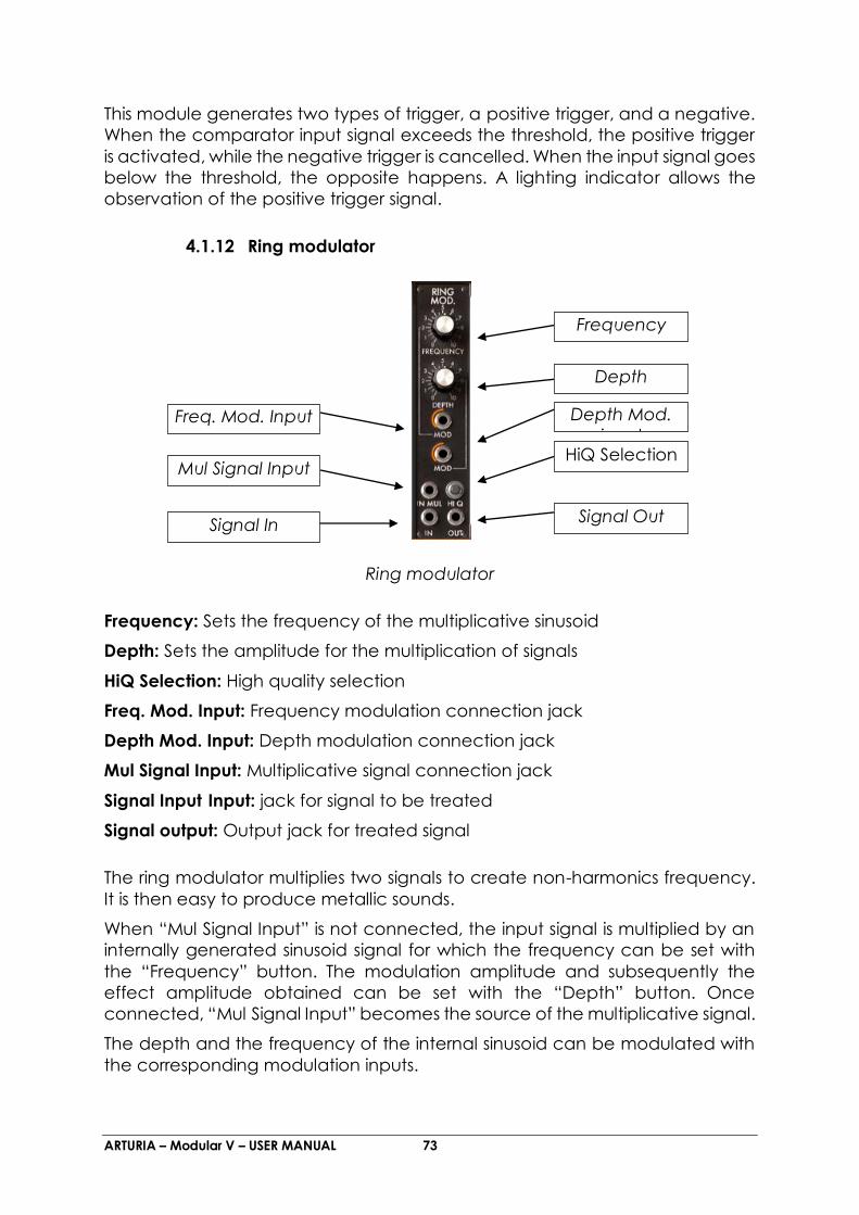
ARTURIA – Modular V – USER MANUAL 73
This module generates two types of trigger, a positive trigger, and a negative.
When the comparator input signal exceeds the threshold, the positive trigger
is activated, while the negative trigger is cancelled. When the input signal goes
below the threshold, the opposite happens. A lighting indicator allows the
observation of the positive trigger signal.
4.1.12 Ring modulator
Ring modulator
Frequency: Sets the frequency of the multiplicative sinusoid
Depth: Sets the amplitude for the multiplication of signals
HiQ Selection: High quality selection
Freq. Mod. Input: Frequency modulation connection jack
Depth Mod. Input: Depth modulation connection jack
Mul Signal Input: Multiplicative signal connection jack
Signal Input Input: jack for signal to be treated
Signal output: Output jack for treated signal
The ring modulator multiplies two signals to create non-harmonics frequency.
It is then easy to produce metallic sounds.
When “Mul Signal Input” is not connected, the input signal is multiplied by an
internally generated sinusoid signal for which the frequency can be set with
the “Frequency” button. The modulation amplitude and subsequently the
effect amplitude obtained can be set with the “Depth” button. Once
connected, “Mul Signal Input” becomes the source of the multiplicative signal.
The depth and the frequency of the internal sinusoid can be modulated with
the corresponding modulation inputs.
Frequency
Depth
Freq. Mod. Input Depth Mod.
input
Mul Signal Input HiQ Selection
Signal Out Signal In

ARTURIA – Modular V – USER MANUAL 74
The “HiQ” interrupter, at the cost of an increase in calculation load, increases
the quality of the sound.
4.1.13 Formant filter
Formant filter
Frequency: Sets the frequency
Resonance: Sets the resonance
Gain: Sets the gain
FM Input: Frequency modulation connection jack
RM Input: Resonance modulation connection jack
GM Input: Gain modulation connection jack
Vowel: Setting of o pre-selected vowel
VM Input: Connection jack for the modulation of the vowel pre-selections
This module regroups four bell filters connected in a series. Each filter can be
set and modulated, independently of the others, in frequency, gain and
resonance (or bandwidth).
It is possible to preset these four filters to reproduce the formation of a particular
vowel with the “vowel” selection window. This preselection can also be
modulated with the associated modulation input.
The preselection is done before the filter settings. It is thus possible, during a
modulation, to make the vowel evolve, and to gently change the settings.
Frequency
Resonance
Gain
FM Input
RM Input
Gain Mod
Input
Vowel Mod.
Input
Input Vowel
Output
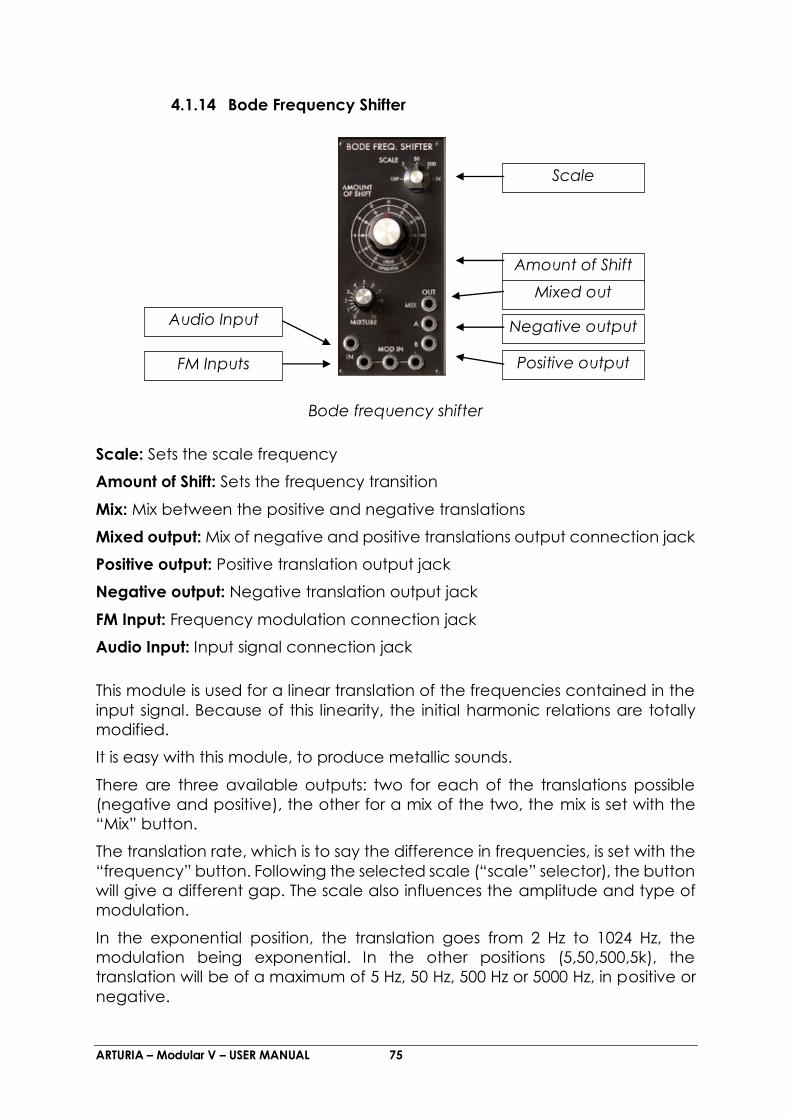
ARTURIA – Modular V – USER MANUAL 75
4.1.14 Bode Frequency Shifter
Bode frequency shifter
Scale: Sets the scale frequency
Amount of Shift: Sets the frequency transition
Mix: Mix between the positive and negative translations
Mixed output: Mix of negative and positive translations output connection jack
Positive output: Positive translation output jack
Negative output: Negative translation output jack
FM Input: Frequency modulation connection jack
Audio Input: Input signal connection jack
This module is used for a linear translation of the frequencies contained in the
input signal. Because of this linearity, the initial harmonic relations are totally
modified.
It is easy with this module, to produce metallic sounds.
There are three available outputs: two for each of the translations possible
(negative and positive), the other for a mix of the two, the mix is set with the
“Mix” button.
The translation rate, which is to say the difference in frequencies, is set with the
“frequency” button. Following the selected scale (“scale” selector), the button
will give a different gap. The scale also influences the amplitude and type of
modulation.
In the exponential position, the translation goes from 2 Hz to 1024 Hz, the
modulation being exponential. In the other positions (5,50,500,5k), the
translation will be of a maximum of 5 Hz, 50 Hz, 500 Hz or 5000 Hz, in positive or
negative.
Scale
Amount of Shift
Mixed out
Negative output
Positive output
Audio Input
FM Inputs

ARTURIA – Modular V – USER MANUAL 76
4.2 Second section
4.2.1 Description
The second section of the Modular V regroups all of the effect modules and
the sequencer. The outputs and inputs of this page needing connections with
the modules of the first section are moved to the latter, in a small extension.
This section contains a module for equalization through a bank of resonant
filters, a chorus module, a phaser, a stereo delay module, and a type 960
sequencer.
The 3 effect modules, filter bank, chorus and stereo delay are applied to the
signal of the output amplifiers in function with the interrupters “VCA1” and
“VCA2”. They are applied in the predefined order.
The choice between the chorus and the phaser is done through a menu
displayed by clicking on the name of the module.
4.2.2 Resonant filter bank
Filter bank
Gain: Sets the band level to positive or negative
Resonance: Sets the bandwidth
Gain
Resonance
Reset Connection
VCA1-VCA2
Output gain

ARTURIA – Modular V – USER MANUAL 77
Connection VCA1-VCA2: Connection of the filter bank to the VCA1 or VCA2
output
Output Gain: Sets the output gain
Reset: Resets the filter bank
This module allows the equalization of the signal coming from the 2 output
amplifiers in function with the state of the interrupters “VCA11” and “VCA2”.
This equalization is done with the help of the resonant filters and has 14 bands.
Each has a level (amplification and alleviation) and bandwidth setting,
excepting the first and last bands, which are respectively, the low-pass and
high-pass filters.
The cut-off frequencies of these filters are fixed at the following values: 80 Hz,
125 Hz, 175 Hz, 250 Hz, 350 Hz, 500 Hz, 700 Hz, 1000 Hz, 1400 Hz, 2000 Hz, 2800 Hz,
4000 Hz, 5600 Hz and 6400 Hz.
A button allows the resetting of the default values and a rotating button sets
the output level after filtering.
4.2.3 Chorus
Chorus
Types: Sets the 3 chorus Types
Rate
Depth Time
Stereo Rate Stereo
Width
Wet Dry
VCA1-VCA2
Types

ARTURIA – Modular V – USER MANUAL 78
Rate: Sets the chorus rate
Depth: Sets the depth of the chorus action
Time: Sets the delay applied to the input signal
Stereo Rate: Sets the speed of the stereophonic evolution
Stereo Width: Sets the width of the stereophonic space
Dry: Sets the gain applied to the input signal
Wet: Sets the gain applied to the treated signal
VCA1-VCA2: Connection of the chorus to the output of VCA1 or VCA2
A Chorus module allows the treatment of the signal coming from the 2 output
amplifiers, eventually treated by the equalizer, in function with the state of the
interrupters “VCA1” and “VCA2”.
The chorus module allows a frequential blurring where the speed is set by the
“speed” knob, the amplitude by the “depth” and the width with the “Delay”.
This frequency blurring is different for the left and right tracks. This allows us to
get a stereophonic signal from a monophonic signal. The difference between
the 2 tracks can be set with the “stereo width” and the speed of the left right
rotation with the “stereo rate” knob.
A selector presents the choice of chorus type: simple, medium, complex.
The input signal level and treated signal can be respectively set with the “gain
direct” and “gain effect” knobs.
4.2.4 Phaser
Phaser
Sweep
Resonance
Amount
Stereo width
Wet Dry
VCA1-
VCA2
Stages Rate

ARTURIA – Modular V – USER MANUAL 79
Amount: Sets the depth of the phaser action
Rate: Sets the speed of the phaser
Sweep: Sets the phaser resonance
Stereo width: Sets the width of the stereo space
Dry: Sets the gain applied to the input signal
Stages: Sets the phaser type (6 or 12 stages)
Wet: Sets the gain applied to the treated signal
VCA1-VCA2: Connects the phaser to the VCA1 or VCA2 output
The phaser module treats the signal coming from the 2 output amplifiers,
eventually treated by an equalizer, in function with the state of the 2 “VCA1”
and “VCA2” interrupters.
The action consists of dephasing the input signal and combining it with the
original signal. Thus we can have a filter that combs (with notches) the
frequency spectrum to the rhythm of an oscillator which follows the frequency
set with the “rate” button. The “depth” button sets the amplitude for the action
of the filtering, while “Resonance” amplifies certain harmonica. The rotating
“stereo width” button sets the amplitude of the stereophonic aspect of the
phaser. When the “stereo width” is set to 0, the left and the right channel are
in phase. When it is set to 0.5, the sound seems to rotate, and when it is set to
1, the sound seem to go from one side to another.
There are two types of phaser, one has 6 levels, the other has 12, set with the
“type” selector. A 6-stage phaser has 3 notches, and a 12-stage has 6.
The rotating “dry” and “wet” buttons are respectively used to set the
amplitude of the original signal and the treated signal.

ARTURIA – Modular V – USER MANUAL 80
4.2.5 Stereo Delay
Stereo Delay module
MIDI sync: Synchronizes delay with the tempo of the host application
Time left: Sets the time of the right track
Time right: Sets the time of the left track
Feedback left: Sets the feedback gain for the right track
Feedback right: Sets the feedback gain for the left track
Feedback to left: Sets the feedback gain of the right track towards the left
track
Feedback to right: Sets the feedback gain of the left track towards the right
track
Dry: Sets the gain applied to the input signal
Wet: Sets the gain applied to the treated signal
VCA1-VCA2 : Connection of the delay to the output of VCA1 or VCA2
A stereo delay module treats the signal coming from the 2 output amplifiers,
eventually treated by the equalizer and chorus, in function with the state of
the interrupters “VCA1” and “VCA2”.
MIDI sync
Time right Time left
Feedback right Feedback left
Feedback to
left
Feedback to
right
Wet Dry
VCA1 & VCA2

ARTURIA – Modular V – USER MANUAL 81
This module allows the repetition of the input signal independently on the left
and right tracks, which explains the presence of 2 columns of controls.
The repetition speed can be set with the “time” knob, while the level of the
repetitions, and eventually the number of audible repetitions is set with the
“feedback” knob. The third knob sends a part of the treated signal to the other
track.
The repetition speed can be synchronized with the tempo of the host
application, and in this case, the “time” knob selects the multiples and sub-
multiples of this tempo.
The levels of the input and treated signals can be respectively set with the
rotating “gain direct” and “gain effect” buttons.
4.2.6 Sequence generator
Sequencer
Also called sequencer, this module is similar to the original 960 sequencer while
simplifying the programming with internal connections.
This module has 3 parts: low frequency oscillator, the 8-step sequence
manager and the output controller.

ARTURIA – Modular V – USER MANUAL 82
Sequencer clock
Frequency: Sets the sequencer clock speed
On: Starts the sequencer
Off: Stops the sequencer
On Input Trigger: Connection of a trigger signal to start the sequencer
Off Input Trigger: Connection of a trigger signal to stop the sequencer
Length: Length of the trigger signal generated by the sequencer
MIDI Synchronization: Synchronization of delay with host application tempo
Fw - Fw/Bw: Select the sequencer mode (forward, or forward/backward)
The low frequency oscillator gives rhythm to the passage from one sequence
to another. The speed can be statically set with the “frequency” knob and
dynamically with the modulation input situated on the first section. The
“synchronization” interrupter synchronizes this generator on the tempo of the
host application. In this case, the “frequency” knob selects multiples and sub-
multiples of this tempo.
The passage from one step to the next can also be done by the means of a
trigger signal (from the keyboard for example) connected to the “next trigger”
input.
The two “On” and “Off” button start and stop this generator. When it starts, it
resets the sequence manager on the first step.
The starting and stopping can be done dynamically with the associated trigger
inputs.
The “length” knob sets the trigger signal width coming from the sequencer.
Frequency
Off
Fw / Rw
Length
On
On / Off Input
Triggers
MIDI Synchronization

ARTURIA – Modular V – USER MANUAL 83
The “backward” interrupter allows a round-trip progression, instead of a
progression indicated by the next step indicators.
Sequencer column
The sequencer has 8 steps. Each step defines 3 output levels with the help of 3
rotating buttons. The manager moves from one step to another at each
impulse of the sequencer clock or upon the reception of a signal on the trigger
input “next trigger”. The led above each of the steps lights up when active.
It is possible to force the sequencer to initialize itself on a particular step, either
by clicking on the “Forcing” button of the desired step, or through a signal in
the associated input trigger.
Every time the sequencer comes to a step, the corresponding trigger output is
activated, allowing the start-up of certain envelopes.
It is possible to remain on a particular step by modifying the “Hold” display. In
this case, we need a certain number of clock impulses from the sequencer (or
from the trigger input) equal to the number indicated to go to the next step.
The rotating selector indicates the next step. It possesses 10 positions, the first 8
represent the next steps, the ninth is a random selection, and the last is the
generator stop.
When this last position is chosen on a step, the sequencer clock is stopped, the
manager is reset on the first step and the outputs set to zero.
At every change of step, a general trigger signal from the sequencer is
activated. This output will be activated at every clock impulse if the
Level Output1
Level Output2
Level Output3
Link
Repetition
Hold
Next Step
On
Forcing trigger
input

ARTURIA – Modular V – USER MANUAL 84
“repetition” interrupter is active. In the same manner, there is no activity from
this signal if the “link” interrupter is inactive.
Sequencer outputs
Smooth 1: Sets smooth for output 1
Smooth 2: Sets smooth for output 2
Smooth 3: Sets smooth for output 3
Smooth 4: Sets smooth for output 4
On Line1: Forcing of the selection from output 4 to output 1
Forcing Trigger Input 1: Forcing trigger input of the selection from output 4 to
output 1
On Line2: Forcing of the selection from output 4 to output 2
Forcing Trigger Input2: Forcing trigger input of the selection from output 4 to
output 2
On Line3: Forcing of the selection from output 4 to output 3
Forcing Trigger Input3: Forcing trigger input of the selection from output 4 to
output 3
Mode Output4: Choice of progression mode of output 4
The control section of the sequencer outputs allows the management of four
outputs in function with the current step. The first outputs take their values from
the values specified by the rotating buttons of the current step, eventually with
a smooth that can be set with the “smooth”.
The fourth output, for which the smooth can also be set with a “smooth” knob,
is managed in the following manner. It takes the value of one of the 3 outputs
Smooth1
Smooth2
Smooth3
Smooth4
On Line 1
Forcing Trigger Input 1
On Line 2
Forcing Trigger Input 2
On Line 3
Forcing Trigger Input 3
Mode Output 4

ARTURIA – Modular V – USER MANUAL 85
in function with the current step and the type of progression specified by the
“Mode output 4” selector.
When placed in the “none” position, the fourth output takes the output value
selected by the “Forcing Line” button and its corresponding trigger input. It is
therefore possible to have 3 different sequences, activated either manually by
a click or dynamically by a trigger.
When the “Mode Output 4” selector is placed on the “L123” position, the fourth
output will automatically cross outputs 1,2 and 3 each time the current step
arrives on the eighth step. In this manner, it is possible to have a 24-step
sequence. Placed at the “L321” position, the lines will be done in the inverse
order. In the same manner, on the “L12” “L13” or “L23” positions, the fourth
output will cover lines 1 and 2, or 1 and 3, or finally 2 and 3, thus obtaining 16
step sequences.
When the “Mode Output 4” selector is placed on the “C123” position, the
fourth output covers lines 123, but the change takes place at every sequencer
clock impulse. We just need to wait for 3 impulses at every step, to alternatively
have lines 1,2 and 3 of each of the steps. The functioning is the same on
positions “C321”, “C12”, “C13” and “C23”.
On the “Rand” position, the choice of fourth output is random.
4.3 Third Section
A small section has been added bellow the connection section. It regroups all
of the external input-outputs on the sequencer, and the key follow outputs.
You will also find an interrupter which activates A440.
The output jacks “External audio” are used to treat the external signals and use
the Modular V as an effect.
The “Out” jacks correspond to the two left and right output jacks on the
Modular V. It is thus possible to loop it to itself and obtain special effects.
Internal connections
4.4 Fourth section
The fourth section contains a virtual keyboard, control for the 4 key follows, 2
modulation surfaces, and a few shortcuts to the most frequently used settings
(Envelope for the 2 output VCA and cut-off frequency settings for the 3 filters).
You will also find general settings like choice of Monophonic/polyphonic, the
“retrigg” mode or “legato”.

ARTURIA – Modular V – USER MANUAL 86
It is also in this mode that we find the volume control and general tuning.
4.4.1 Keyboard follow management
Keyboard follow
Slope: Sets the slope of the keyboard follow
Pivot: Selects the pivot note of the keyboard follow
Threshold: Selects the threshold note of the keyboard follow
Low/High: Selects the low (high) note of the generator for the trigger of the
keyboard follow
High: Selects the high note of the generator for the trigger of the keyboard
follow which can also be inverted
Bend/Portamento: Request for affectation of a pitch bend (portamento) or
glissando to the keyboard follow
There are four independent keyboard follows. Each possessing a slope setting
with the “Slope” knob, a pivot note chosen in the “pivot” display and a
threshold note chosen with the “threshold” display begin from which the slope
is null.
Keyboard follow management
Slope
Pivot Threshold
Low/High
Bend/Portamento

ARTURIA – Modular V – USER MANUAL 87
Each of the keyboard follows can generate a trigger signal. Two displays allow
the choice of a low and high note. When the keyboard detects a note
between the 2 limits, the trigger signal is active as long as the note remains
active. When the note is outside of the limits, the trigger signal remains inactive.
If the notes selected for the upper and lower limits are such that the lower note
is higher than the upper, then the note detected by the keyboard must be
outside of the limits to activate the trigger signal.
The “Portamento” and “PitchBend” buttons of each of the keyboard follows
allows the affectation of a portamento or pitch bend. The pitch bend can be
inverted (the modulation is negative when the command is positive), which
allows us, for example, to lower the filter cut-off frequency insofar as the tuning
of the oscillators is raised.
It is also possible to replace the portamento (continuous glide of the
frequency) with a glissando (frequency glide by semi-tone)
4.4.2 General settings
General settings
Course Bend (filter): Filter coarse for the pitch bend wheel
Course Bend (accord): Oscillator tuning coarse for the pitch bend wheel. (by
semitone from 0 to 4 octaves)
MonoPoly: Selects synthesizer mode: ( Monophonic, Unison or polyphonic )
Legato: Selects legato mode (the portamento is active when the notes are
detached).
Re Trigger: Selects the re trigger mode (the keyboard generates a trigger when
the notes are linked)
Nbr Release: Select the number of release notes
Poly: Gives the number of polyphonic tracks (16-32-64)
The Modular V responds to the pitch bend depending on the position of the
“tune” selector. This selector sets the amplitude of this response to +/- four
octaves per semi-tone.
The knob close at hand noted “filter”, allows the setting of the excursion of the
response to the tuning wheel for the filter cut-off frequency,
Course Bend
(filter)
Course Bend
(tune)
Mono
Legato Re Trigger
Poly

ARTURIA – Modular V – USER MANUAL 88
The “MonoPoly” interrupter takes the synthesizer from monophonic to
polyphonic mode. The Unison position allows us to play the indicated number
of voices in parallel, while the playing mode remains monophonic.
In the monophonic mode, 2 interrupters allow the control of the triggering of
the envelopes. The first, “re trigger” allows the reactivation of the trigger signal
in the case where the notes are linked. The second, “legato” allows the
affectation of frequency smoothing (portamento) whether the notes are
linked or not.
The rotating “Volume” button sets the general volume of the Modular V, while
the rotating “tune” button allows us to set the tuning with amplitude of 1 tone.

ARTURIA – Modular V – USER MANUAL 89
5 The basics of subtractive synthesis
Of all of the forms of sound synthesis, subtractive synthesis is still one of the
oldest and most frequently used today. This method was developed from the
60’s on Bob Moog’s analog synthesizers, and then later on ARP, Buchla,
Oberheim, Sequential Circuits (Prophet series), Yamaha (CS series), Roland,
Korg (MS and PS series) to name but a few. This synthesis technique is still used
on most of the current digital synthesizers, added to sample reading or wave
tables, which have progressively replaced analog oscillators since the 80’s. The
origninal modular systems, and your Modular V, represent the best illustration
of the immense possibilities of subtractive synthesis.
Modular synthesizers use a certain number of base modules, placed in sections
where the size varies in relation to the importance of the systems. These
modules, once connected, allow the creation of a multitude of sounds.
5.1 The three main modules
5.1.1 The oscillator or VCO
The oscillator (Voltage Controlled Oscillator) can be considered as the starting
module (with the noise module that we often class among the oscillators) for
the creation of a sound on a modular system. It is here that the first sound signal
is created and we can consider the oscillator like the strings of a violin which,
when stroked or plucked, vibrates to create a sound.
The main oscillator settings are the pitch and the waveform.
The pitch is determined by the oscillation frequency. The oscillator frequency
setting is done with two controllers: firstly the Range selector which mainly
determines the fundamental frequency, often expressed in feet: 32,16,8,4,2 —
the highest number (32) gives the deepest tone, and on the other hand, 2 gives
the highest tone; Secondly, the frequency setting which will tune the oscillator
more precisely.
The waveform determines the harmonic richness of the audio signal. 4
waveforms are available on the Modular V: sawtooth, square/PW, triangle and
sinus.
The sawtooth is the richest audio signal of the 4 available waveforms (it
contains all of the harmonics at decreasing volume levels in high
frequencies). Its “brassy” sound is ideal for brass sounds, striking bass
sounds or rich accompaniments.

ARTURIA – Modular V – USER MANUAL 90
Sawtooth waveform
The square possesses a more “hollow” sound than the sawtooth (it only
contains impair harmonics) but nevertheless, its sonic richness (notably
in the low frequencies) could be used for sub basses emphasized in the
mix (the square oscillator should be thus set an octave below the that of
the saw tooth), wooden sounds (clarinet if the square signal is a little
filtered), etc.
The PWM (Pulse Width Modulation) is a setting which allows the
modification of the square ware form cycle (or wave width). This can be
done manually with the “PW” knob or through modulation (using an
envelope or a LFO). This variation of impulse width is translated by a
spectrum modification, not unlike a waveform change.
Unlike classic analog synthesizers, the Modular V allows you to change the
impulse width through not only the square waveform, but also the sawtooth
and triangle. This offers a large number of sonorities on top of the base signals.

ARTURIA – Modular V – USER MANUAL 91
Square waveform
The triangle could be considered like a much-filtered square signal (thus
very soft). It is very poor in harmonics (impair equally) and will be very
useful for creating sub basses, flute sounds, etc.
Triangle waveform
The sinusoid is the purest waveform of them all. It is composed of a single
fundamental harmonic and produces a very “damper” sound (the
tonality of a telephone is sinusoid). It will be used to reinforce the low

ARTURIA – Modular V – USER MANUAL 92
frequencies of a bass sound or as a frequency modulator in order to
create harmonics that do not exist in the original waveforms.
Sinusoid waveform
A frequency modulation (FM) can be created between 2 oscillators by
connecting the audio output from a first sinusoidal oscillator to the modulation
input of a second oscillator. On the Modular V, if you turn the modulation rate
ring, you will obtain a sound richer in harmonics. If you introduce a square or
sawtooth signal, the result can be quickly distorted… but interesting for
inharmonic sonorities like bell sounds or special effects for example.
Frequency Modulation
The synchronization of an oscillator on another brings about complex
waveforms. If, for example, you synchronize oscillator2 on oscillator1, oscillator2
will restart another period each time the first oscillator accomplishes a
complete period, even if oscillator2 has not completed a full period (which
signifies that it is not tuned to the same tonality.) The higher you tune oscillator2,
the more you will obtain composite waveforms.
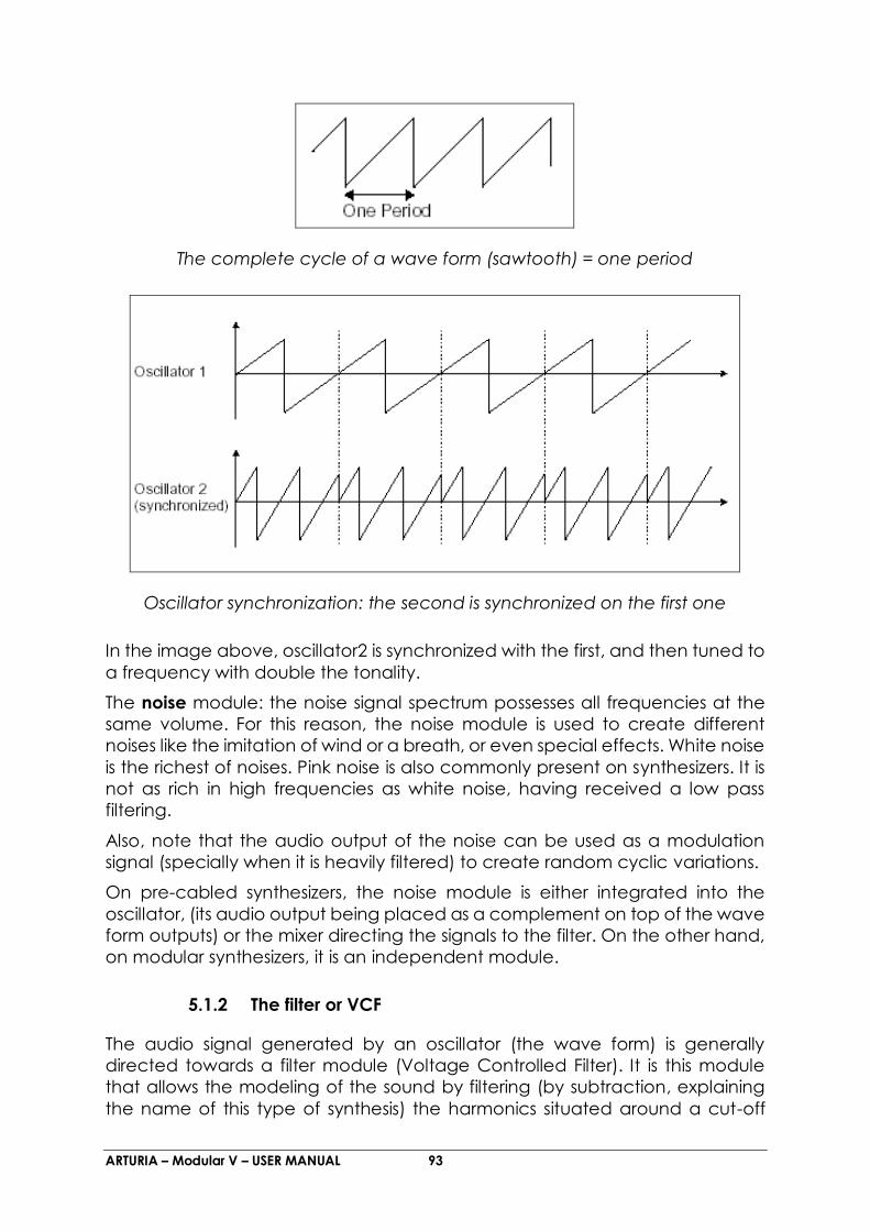
ARTURIA – Modular V – USER MANUAL 93
The complete cycle of a wave form (sawtooth) = one period
Oscillator synchronization: the second is synchronized on the first one
In the image above, oscillator2 is synchronized with the first, and then tuned to
a frequency with double the tonality.
The noise module: the noise signal spectrum possesses all frequencies at the
same volume. For this reason, the noise module is used to create different
noises like the imitation of wind or a breath, or even special effects. White noise
is the richest of noises. Pink noise is also commonly present on synthesizers. It is
not as rich in high frequencies as white noise, having received a low pass
filtering.
Also, note that the audio output of the noise can be used as a modulation
signal (specially when it is heavily filtered) to create random cyclic variations.
On pre-cabled synthesizers, the noise module is either integrated into the
oscillator, (its audio output being placed as a complement on top of the wave
form outputs) or the mixer directing the signals to the filter. On the other hand,
on modular synthesizers, it is an independent module.
5.1.2 The filter or VCF
The audio signal generated by an oscillator (the wave form) is generally
directed towards a filter module (Voltage Controlled Filter). It is this module
that allows the modeling of the sound by filtering (by subtraction, explaining
the name of this type of synthesis) the harmonics situated around a cut-off

ARTURIA – Modular V – USER MANUAL 94
frequency. It can be considered like a sophisticated equalizer, which reduces,
depending on the case, the low or high frequencies of a sound.
The removal of unwanted frequencies from a cut-off frequency is not sudden,
but is done progressively, depending on the filter slope. This filter slope is
expressed in dB/octave. The filters used in classic analog synthesizers have
slopes of 24 dB/octave or 12 dB/octave.
The 24 dB/octave offers a more efficient filtering than the 12 dB/octave.
On the Modular V, you have access to 7 different types of filtering. Let’s have
a look at their respective properties.
The low-pass filter (LPF) deletes the high frequencies from a frequency limit (the
famous cut-off frequency) and only allows mow frequencies to pass.
Depending on the setting, we will hear the sound becoming more or less
“brilliant”, or more or less “thick”.
This is the type of filtering that you will commonly find on synthesizers using
subtractive synthesis. It is equally present on analog synthesizers as well as the
most recent digital models.
Low-pass filter
The high-pass filter (HPF), as opposed to the low-pass, eliminates low
frequencies and only allows high frequencies past. The sound will thus become
“finer”. It is very useful for removing redundant low frequencies.

ARTURIA – Modular V – USER MANUAL 95
High-pass filter
The band-pass filter (BPF) eliminates the frequencies situated on either side of
the cut-off frequency. Use it to make a certain band of frequencies that you
wish to emphasize appear. This will make the sound more “pinched”.
Band-pass filter
The band-reject filter (notch) eliminates the frequencies inside a band of
frequencies. This filter is above all else interesting when we want to vary this
band of frequencies (with the “frequency” on the Modular V filters or the
modulation of an LFO on this same parameter). You will thus obtain a sound
close to a “phasing” effect.
Band-reject filter

ARTURIA – Modular V – USER MANUAL 96
These 4 types of filtering are more often used on analog synthesizers.
The Modular V offers 3 other types of filters, unheard of on synthesizers, but very
much used on high quality mixing consoles or professional equalization
modules:
The bell filter amplifies or dampens a frequency band (in function with the gain
knob).
Bell filter
The low-shell filter amplifies or dampens the frequencies under the cut-off
frequency (with the action of the gain knob).
Low-shell filter
The high-shell filter increases or decreases the frequencies above the cut-off
frequency (with the action of the gain knob).

ARTURIA – Modular V – USER MANUAL 97
High-shell filter
A second setting completes the cut-off frequency: the resonance. You will also
find it under the terms “emphasis” or “Q” – as a “filtering quality factor”.
The resonance amplifies the frequencies close to the cut-off frequency; the
other remaining frequencies are unchanged (before the cut-off frequency) or
diminished (after the cut-off frequency).
You can increase the rate of resonance by simply turning the resonance knob.
When you increase the resonance, the filter becomes more selective, the cut-
off frequency is amplified, and the sound begins to “whistle”.
With a high level of resonance, the filter will begin to oscillate on its own,
producing a sound close to a sinusoidal waveform. At this stage, the use of a
key follow is very important as you can create a melody by tuning the filter cut-
off frequency with the frequency of the oscillators.
Filter resonance, noted as “Q”
5.1.3 The amplifier or VCA
The amplifier (Voltage Controlled Amplifier) is charged with receiving the
audio signal coming from the filter (or directly the one from the oscillator if it is
not filtered) to adjust its volume with a knob, before the signal is directed to the
speakers.

ARTURIA – Modular V – USER MANUAL 98
In conclusion, here is a scheme that may help you to understand the
composition of a basic sound:
5.2 Complementary modules
The keyboard
If we hold down a key at this stage, the sound you will get from the speaker will
be uniform, without life and without end. In fact, the oscillator delivers a
continuous signal (the audio output of a wave form) of a fixed pitch. In the
scheme above, the only means of stopping this sound that quickly becomes
unsupportable is by lowering the filter cut-off frequency so that it becomes
more and more thick until it disappears; or more simply, to lower the volume of
the amplifier.
To trigger and stop this sound, and this, at the tone that we want, we use a
keyboard, which will be connected to the oscillator. This will “play” as soon as
a key is pressed and will mute it as soon as released. Of course, this connection
is made through MIDI (it replaces the “gate” type connection of analog
synthesizers, which triggers the sound when the key is pressed and stops when
released).
In the second case, so that the sound is correctly tuned with the keyboard
notes, we need to apply a key follow modulation (replacing the 1Volt/octave
control present on most analog synthesizers).
To play the Modular V with a MIDI keyboard, click on the “trigg in” plug of
the output VCA and select the “keyboard trigger” function. For more detail,
see chapter 5 paragraph 1.1.5 “Output Amplifiers (VCA)”. Next select one of
the 4 key follow settings in the display “S1…4,off” on each “Driver” oscillator.
If you don’t have a keyboard, you can play on the Modular V virtual keyboard.
5.2.1 The envelope generator
The envelope generator, connected to the amplifier, is used to “sculpt” the
form of a sound during a cycle, which begins when we press a note on the
keyboard, and ends when we release.
The most current envelope modules use 4 settings that we can vary:

ARTURIA – Modular V – USER MANUAL 99
The Attack is the time that the sound will take to reach its maximum
volume once the key has been pressed on the keyboard.
The Decay is the time that the sound will take to decline after the key is
played.
The Sustain is the maximum level of volume that the sound will reach
when a key is pressed.
The Release is the decline time after the key has been released.
The ADSR envelope
On the two VCA of the Modular V, the envelopes include 2 supplementary
settings:
The Slope Time is the time of intermediary decline situated after the decay,
once a key is pressed.
The Slope Level is the level of intermediary decline situated after the decay,
once a key is pressed.
The envelope generator can also be used to modulate other settings like the
cut-off frequency of a filter or an oscillator for example.
5.2.2 The low frequency oscillator
The LFO (Low Frequency Oscillator) possesses, among other things, the same
characteristics as classic oscillator but does produce frequencies inferior to 20
Hz. In other terms, you won’t hear the sound if you connect the audio output
of an LFO in an amplifier.
Not being used to produce a sound, it can be used to create a cyclic
modulation on the parameter on which it is connected.
For example: if you connect an LFO to the modulation input of an amplifier,
the sound volume will increase and disappear in an alternate manner
depending on the speed (the frequency) of this LFO. This will create a tremolo
effect.

ARTURIA – Modular V – USER MANUAL 100
To produce a vibrato effect, simply connect the sinusoid output of an LFO to
the modulation input of an oscillator. The frequency of this oscillator will thus
be modulated up and then down.
Finally, try to connect an LFO output to the modulation input of a lightly
resonant low-pass filter and you will obtain a wah-wah effect.
VCA modulated by a LFO
Now to finish, the scheme of a full synthesizer containing:
3 oscillators (VCO)
1 noise module
1 mixer (mixing the 3 VCO and the noise module towards 2 filters)
2 filters (VCF)
2 amplifiers (VCA, can be placed in stereo with the pan knobs)
3 envelopes (ADSR)
3 LFO
1 keyboard

ARTURIA – Modular V – USER MANUAL 101
Synthesizer scheme

ARTURIA – Modular V – USER MANUAL 102
6 A few elements of sound design
Here is a series of examples designed to guide you through the creation of a
sound and a sequence. They are classed in order of complexity beginning with
the easiest, and are organized into 4 parts:
The first part will teach you the basics of modular sound synthesis. For this you
will go from the most basic patch (Make a VCO oscillator “ring” in an output
VCA amp) to programming a richer sound (several VCO sources, VCF filters,
VCA envelopes…)
The second will help you to use all of the different aspects of the sequencer
The third will show you tips on the creative use of the key follows, triggers and
the creation of a stereophonic sound without using extra chorus and delay
effects.
The fourth and last part will guide you through the use of three of the new
modules in the Modular V 2.0: the Bode Shifter, the envelope follower and the
Formant Filter.
6.1 Modular sound synthesis
6.1.1 Simple patch #1
To begin, we will learn how to program an elementary monophonic sound. It
will be composed of 4 modules:
an oscillator
a low pass filter
an output VCA
the envelope corresponding to the output VCA.
You will thus obtain the base patch of subtractive synthesis.
If you click on one of the “Inv” buttons on the mixer VCAs, this will not change
the base tone of the preset but will invert the signal connected to this VCA.
(For example, a descending “sawtooth” signal will become ascending)
In addition, if you apply soft clipping (light distortion) on one of the VCA, the
operation will most likely use more CPU load than before.
The following figure shows the connections for this sound as well as the position
of the different knobs:

ARTURIA – Modular V – USER MANUAL 103
Simple patch #1
To begin, load the “Blank_Synth” preset in the “User” / “Blank”.You will notice
that it has no cable connection and it delivers no sound . This is normal, it is
from this preset that you will program your sounds from scratch.
Choose a sound source on the first oscillator situated in the lower section: take
the audio output of the saw-tooth waveform by clicking on the jack . This
wave form produces the richest noise signal out of the 5 wave forms proposed.
It will be ideal for creating a “brassy” sound, for example.
Direct the cable to the input of the first filter (“VC Low Pass Filter”) by dragging
it to the “In” jack. This first cable will come confirming the connection.
Now direct the audio output from this filter (“Out” jack) to the (jack “vca in”)
input of “VCA1” (output amplifier). Make sure that the trigg input of the output
amplifier (VCA1) selects “keyboard trigger”
Now play on your MIDI keyboard and you will hear the sound from your first
patch.
We recommend that you save it as it is as it will come in useful for programming
basic bass or lead sounds. (See the “saving a sound” chapter)
Turn the filter cut-off frequency button progressively to the left to change the
brilliance of the sound. It will become increasingly “soft”.

ARTURIA – Modular V – USER MANUAL 104
6.1.2 Simple patch #2
The sound of your first patch may seem a little empty. Here is how to make the
sound more interesting and “fatter”. This patch will use:
2 oscillators
1 low pass filter
1 output VCA
1 envelope
1 LFO
It will more or less constitute the classic composition of a basic synthesizer.
You will be able to regularly reuse this patch, don’t erase it.
Patch #2 complete
For more clarity, reuse the “Blank” preset.
As previously, connect the “saw” output of oscillator1 to the first mixer VCA
input. Next, connect the oscillator2 “saw” waveform to the second VCA.

ARTURIA – Modular V – USER MANUAL 105
Connection of oscillators to mixer
Create a link between these 2 VCA by clicking on the “link” button situated
between the first and second VCA. This will allow you to mix these 2 sources
before directing them towards the audio input of filter1.
Click on the link button to create a link between the 2 VCA
To connect the audio output coming from the 2 mixed VCA to the filter1 input,
drag a cable from the first VCA “out” to the filter1 “in”.

ARTURIA – Modular V – USER MANUAL 106
Link towards filter1
As was the case with the previous patch, direct the filter output towards the
audio input of the output VCA 1.
Now increase the volume of these 2 VCA (volume knobs) so as to hear the
sound coming from the 2 oscillators.
Setting of the volume of the 2 mixer VCA
To give more life to your sound, click on the “frequency” knob on the first
oscillator with the right click of the mouse (“Fine tune” position) then lightly turn
towards the right (to increase the height of its tone) or the left (to decrease it).
You will thus progressively hear a beating resulting from the light difference in
tuning of the 2 oscillators. This beat will create a chorus effect, which will give
more life and “warmth”.

ARTURIA – Modular V – USER MANUAL 107
Detuning of oscillator1
Hone this sound by applying light cyclic variations on the filter cut-off
frequency. Choose, for example, the “Sin” output of LFO1 and direct it to the
first modulation input (“Mod In”) of filter1. Click again on this jack and lightly
turn it towards the right (to 2 o’clock for example). This will dose the modulation
input to the cut-off. Finally, lower the cut-off frequency to hear the oscillation
of the sound.
Connection of LFO to filter1
Turn the resonance button to the right to create a supplementary “brilliance”
that is very “electronic” in your sound. By increasing the oscillation speed of
LFO1 (“frequency” button), you will thus obtain a typical 70’s “wah-wah”
effect.

ARTURIA – Modular V – USER MANUAL 108
6.1.3 Complex patch #1
Let’s continue with a more complex sound using:
3 oscillators
the mixer
2 low pass filters
2 VCA
2 envelopes (1 on each filter)
2 LFO
This sound will be polyphonic and constitute a good example of
accompaniments with subtle stereo evolutions.
The complete patch
For the conception of this sound, you can complete the previous patch.
Start by clicking on the “link” button between the second and third mixer VCA
to create the link between these 3 VCA.
Then, on this third slice, connect the audio output of the square waveform of
the third oscillator.
Notice that filter1 is still connected to the audio output of the first slice of the
mixer. As a result, it now receives the signals coming from the 3 oscillators.
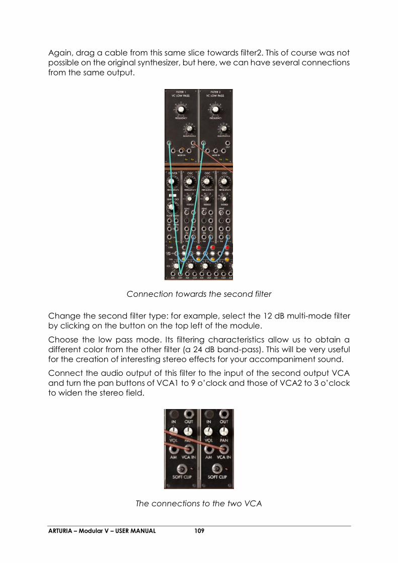
ARTURIA – Modular V – USER MANUAL 109
Again, drag a cable from this same slice towards filter2. This of course was not
possible on the original synthesizer, but here, we can have several connections
from the same output.
Connection towards the second filter
Change the second filter type: for example, select the 12 dB multi-mode filter
by clicking on the button on the top left of the module.
Choose the low pass mode. Its filtering characteristics allow us to obtain a
different color from the other filter (a 24 dB band-pass). This will be very useful
for the creation of interesting stereo effects for your accompaniment sound.
Connect the audio output of this filter to the input of the second output VCA
and turn the pan buttons of VCA1 to 9 o’clock and those of VCA2 to 3 o’clock
to widen the stereo field.
The connections to the two VCA

ARTURIA – Modular V – USER MANUAL 110
You make your sound fuller, lightly detune the frequencies of the 3 oscillators
by turning their respective “Fine Tune” buttons (by clicking with the right mouse
button) to create a chorus effect.
Connect the envelope1 output to the first modulation input of filter1. Click
again on the jack and turn it lightly (to 2 o’clock for example) towards the right.
This will dose the modulation input directed towards the cut-off. Do the same
thing on filter2 using envelope2.
If you do not hear the sound, make sure with a right click on the “trigg” inputs
of these 2 envelopes that “keyboard trigger” has been selected.
Apply light cyclic variations on the filter1 cut-off frequency. Choose the “Sin”
output of LFO1 and direct it to the first modulation input of filter1. Lightly turn
the jack to the right (to 2 o’clock for example), this will dose the modulation
input directed towards the cut-off. Lower the cut-off frequency to clearly hear
the oscillation of the sound.
Do the same thing with filter2 by choosing the triangular waveform of LFO1. To
create subtle evolutions of stereo sound, turn the modulation jack ring in the
opposite direction of filter1.
LFO1 to the filters link
If you wish to change the LFO oscillation speed, simply turn the “Frequency”
button.
You can also create light fluctuations in the change of speed of LFO1. For this,
connect the LFO2 output to the “FM” input (Frequency Modulation) of
LFO1. Turn the jack ring to dose the modulation. The evolution of the 2 filters will
be less linear.

ARTURIA – Modular V – USER MANUAL 111
An accompaniment sound has a fairly slow attack, set the 2 VCA envelopes
so that the sound appears more slowly when you press the keys of your
keyboard. Turn the 2 attack buttons (“Attack” — A) to the right: set them to 2
seconds for example.
Hone the setting of these envelopes by prolonging the decay of the sound:
turn the 2 release buttons (“Release” — R) lightly increasing them (to 500
millisecond for example)
The setting of the VCA envelopes
6.1.4 Complex patch #2
This fourth example will let you go a little further in the approach of different
types of modulations. It contains:
4 oscillators (the second being in “synchro” mode with the third)
1 white noise
3 filters (1 LP, 1 HP & 1 BP)
2 VCA (in stereo)
3 auxiliary envelopes
3 LFO (the 2 principal LFO + 1 low frequency)
This sound is stereo and uses delay and chorus effects. It can be as easily used
in monophonic and polyphonic mode to create a very expressive ambient
sound.

ARTURIA – Modular V – USER MANUAL 112
The complete patch
For this example, we recommend that you start over with the patch #2 base.
Successively connect the outputs of the waveforms of oscillators 3 and 4
to the VCA inputs 3 and 4 of the mixer.
Set the “Range” of oscillator 3 to 16. It will play 1 octave upper than the 3 others
Connect the white noise output to the third filter and choose the third type of
filter on this (the Filter Coupler). It will be very useful in creating a resonance
particular to white noise. For this set it to Band Pass mode.
Connect the audio output of this filter to the audio input of the fifth mixer VCA.
Connect envelope1 to one of the filter3 modulation inputs and set the
modulation level to your liking.
Increase the attack time of the envelope to 2 o’clock in order to make the
sound progressively appear in the global sound.
Now let’s make another modulation appear given by the of LFO2 which
will be provoked by the aftertouch. For this, connect the “Tri” output of this LFO
to the sixth audio input of the mixer.

ARTURIA – Modular V – USER MANUAL 113
Connect the “Aftertouch” output to the “Mod” input of this same slice, and
direct its output to the second “Mod” input of filters1 & 2, without forgetting to
increase the 2 modulation levels.
The white noise module connected to the band pass filter
Set the third filter output towards the fifth slice of the mixer and link slices 3, 4
and 5 to direct them towards the first and second filters.
The mixing

ARTURIA – Modular V – USER MANUAL 114
On the fourth oscillator, set the “synchro” mode to “ON” and to “Hard” type.
Then, turn the “frequency” button to find the color and height of the sound
that you like. This will also be modulated by a third LFO (for this take the “Sin”
output of oscillator 7 and set it to “Low” mode so that it acts as a LFO).
To save on CPU load, also click on the “Key F” (for Key Follow) button to
deactivate the keyboard connection mode. The frequency will thus be fixed.
Modify the waveform width for and on the first 3 oscillators by
connecting the triangle output of LFO2 to the impulse modulation input
(“PWM”) of the first “driver” oscillator. This will add new harmonic colors typical
of analog synthesizers. Set the Pulse Width knob value towards the middle so
that the sound does not disappear when the pulse width is at 10% (equivalent
to the closed position of this knob).
Manual pulse width setting
Set the resonance button of the first 2 filters to 9 o’clock and connect the “Sin”
wave forms of LFO1 to one of their modulation inputs.
Next set the 2 modulation levels and the LFO speed to your liking.
Finally, set the 2 output VCA envelopes as you wish, while trying to keep the
same values on the 2 envelopes.
If you apply several modulations provoked by the different LFOs and on
different destinations (filter “Cutoff”, FM, PWM etc…), try to vary the different
levels of modulation in order to create as many different variations in the
evolution of the final sound. This is one of the strongest points of modular
synthesizer.

ARTURIA – Modular V – USER MANUAL 115
6.2 The sequencer
6.2.1 Sequence #1
Now let’s take a more detailed look at the use of the sequencer. We’ll start by
creating a simple sequence of notes with an oscillator. Take, for example,
patch #1 from this chapter as the starting point.
At the bottom of the first “Driver” oscillator, click once on the sequence display
(situated next to the one for the key follows): the display indicates “S1”. This
activates the connection towards the first line of sequence on the sequencer.
Connection of the “driver” oscillator to the first sequence line
Select the “Seq Trig” output by clicking on the “Trig” input of VCA1.

ARTURIA – Modular V – USER MANUAL 116
Selection of Sequencer trigger
Now move to the second screen and click on the “ON” button situated in the
“Oscillator” module. The sequencer starts up but you only hear the same pitch
for all the steps. This is normal.
Start the sequencer
Set each knob corresponding to the first sequencer line (the one to which the
sequencer oscillator had been directed). You can now hear a melody.

ARTURIA – Modular V – USER MANUAL 117
Set the knobs of the first line of sequence
Set the impulse width of the square signal of the sequencer oscillator with the
“Length” knob. This will vary the length of the notes played.
Set the “Length” knob
To stop the sequencer, click on the “OFF” button.
6.2.2 Sequence #2
Now let’s see how to use the different combinations between knobs (by lines
or columns to create 8, 16 or 24 step sequences). This will allow you to quickly
have very different sequence lines available which although different will
harmonize perfectly together. We will also look at the possibilities for the
creation of ternary sequences (for example: 6, 12 or 18 steps).
To begin, reuse the previous sequence...
Click 4 times on the sequence display at the bottom of the first “Driver”
oscillator (the display indicates “S4”). This will connect the latter to the fourth
sequence output. This will allow us to create knob line or column combinations.
Select the “L1-2” function on the line selector on the right of the sequencer.
Once you have created a melody on the second line, you will alternately hear
the melodies played by these two lines.

ARTURIA – Modular V – USER MANUAL 118
Select the function “L1-2”
Do the same thing for the third line. To hear it, select “L1-2-3” and try the other
selections and the columns (3 knobs per column) by activating “C1-2-3”. With
the “Al” position, the playing will be done randomly between each line and
column.
Now let’s look at the creation of ternary sequences. For this, choose step 1 on
the “Next” step selector of the seventh line. This will force the sequence to reset
at the sixth column. You will thus have a 6 times sequence which can be
synchronized with the MIDI tempo of the host sequencer (VST for example).
Choose step 1 on the seventh line
We can now go much further by moving the sixth time towards the eighth
column. For this, return to the initial order of the sequence (2, 3, 4, 5, 6, 7, 8, 1)
and set the eighth “Next” selector to 3. This time the sequence limits will be
moved three steps forward all while producing the same number of steps.
Try playing on 12 and then 18 steps choosing the “L1-2” and “L1-2-3” functions
or by column (“C1-2-3” etc…) or randomly with the “Al” position. The sequence
playing will always be ternary all while creating multiple variations on the
melody.
Now try to “force” the trigger of a step by clicking on the “ON” button
underneath. The sequence will interrupt its course and continue from this one.
This is interesting for creating other types of sequences.

ARTURIA – Modular V – USER MANUAL 119
“Force” the triggering of a step
You can also “trigger” one of these steps using a MIDI keyboard by selecting
“Keyboard Trigger” on the “Trigg” output above the “ON” button. The
sequence will be triggered when you press one of the notes. In the same
manner, you can switch lines or columns by selecting the same function on the
“Trigg” “Chain” output.
Select “Keyboard trigger” on the “Trigg” output
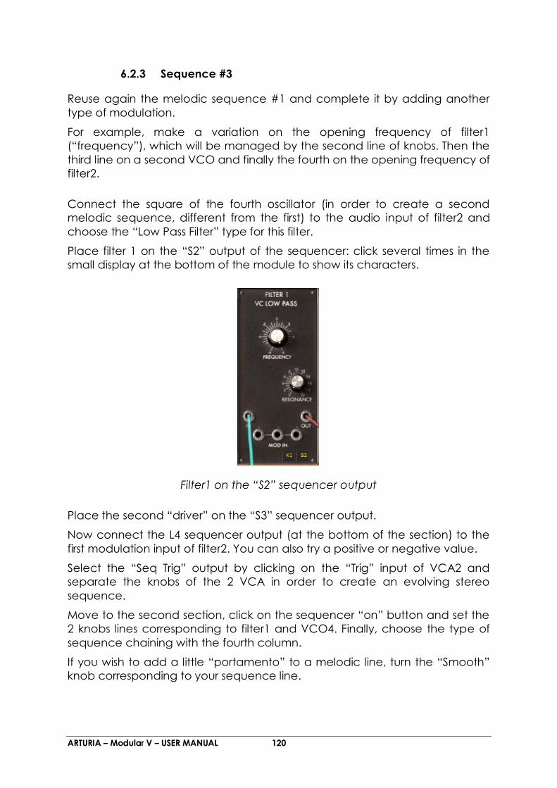
ARTURIA – Modular V – USER MANUAL 120
6.2.3 Sequence #3
Reuse again the melodic sequence #1 and complete it by adding another
type of modulation.
For example, make a variation on the opening frequency of filter1
(“frequency”), which will be managed by the second line of knobs. Then the
third line on a second VCO and finally the fourth on the opening frequency of
filter2.
Connect the square of the fourth oscillator (in order to create a second
melodic sequence, different from the first) to the audio input of filter2 and
choose the “Low Pass Filter” type for this filter.
Place filter 1 on the “S2” output of the sequencer: click several times in the
small display at the bottom of the module to show its characters.
Filter1 on the “S2” sequencer output
Place the second “driver” on the “S3” sequencer output.
Now connect the L4 sequencer output (at the bottom of the section) to the
first modulation input of filter2. You can also try a positive or negative value.
Select the “Seq Trig” output by clicking on the “Trig” input of VCA2 and
separate the knobs of the 2 VCA in order to create an evolving stereo
sequence.
Move to the second section, click on the sequencer “on” button and set the
2 knobs lines corresponding to filter1 and VCO4. Finally, choose the type of
sequence chaining with the fourth column.
If you wish to add a little “portamento” to a melodic line, turn the “Smooth”
knob corresponding to your sequence line.

ARTURIA – Modular V – USER MANUAL 121
Turn the “Smooth” knob
to complete the evolution of the sound in stereo, you can apply modulations
to the cut-off frequencies of the 2 filters using a LFO. To make this effect more
apparent, turn the level of the modulation input of filter1 to the left (negative
value) and of filter2 to the right (positive value). By applying a slow rotation
speed to the LFO, you will get the linking of the 2 sequences in stereo space,
brought about by the opening of the 2 cut-off frequencies.
6.3 Bonus features
6.3.1 Creative use of key follows
The Modular V provides you with settings for 4 independent key follows. These
key follows are mainly used to tune the oscillators in relation to the keyboard
range but can also be used for different applications.
Try, on a filter1 cut-off frequency, opening (click several times on the key follow
display situated at the bottom of the filter to select the “K2” key follow). It will
become increasingly brilliant when the height is increased of the follow slope
is positive and the contrary if it is negative.
Click several times on the key follow display
You can also try another type of VCA control, PWM, oscillator fine tune, LFO
speed… by selecting one of the 4 key follows in one of the modulation inputs.
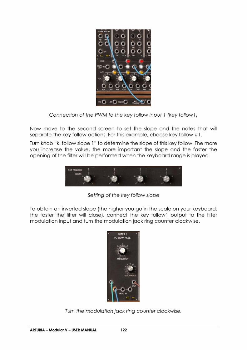
ARTURIA – Modular V – USER MANUAL 122
Connection of the PWM to the key follow input 1 (key follow1)
Now move to the second screen to set the slope and the notes that will
separate the key follow actions. For this example, choose key follow #1.
Turn knob “k. follow slope 1” to determine the slope of this key follow. The more
you increase the value, the more important the slope and the faster the
opening of the filter will be performed when the keyboard range is played.
Setting of the key follow slope
To obtain an inverted slope (the higher you go in the scale on your keyboard,
the faster the filter will close), connect the key follow1 output to the filter
modulation input and turn the modulation jack ring counter clockwise.
Turn the modulation jack ring counter clockwise.
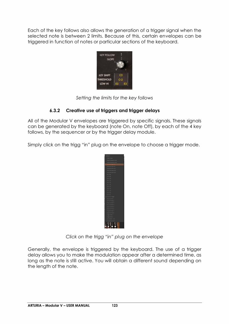
ARTURIA – Modular V – USER MANUAL 123
Each of the key follows also allows the generation of a trigger signal when the
selected note is between 2 limits. Because of this, certain envelopes can be
triggered in function of notes or particular sections of the keyboard.
Setting the limits for the key follows
6.3.2 Creative use of triggers and trigger delays
All of the Modular V envelopes are triggered by specific signals. These signals
can be generated by the keyboard (note On, note Off), by each of the 4 key
follows, by the sequencer or by the trigger delay module.
Simply click on the trigg “in” plug on the envelope to choose a trigger mode.
Click on the trigg “in” plug on the envelope
Generally, the envelope is triggered by the keyboard. The use of a trigger
delay allows you to make the modulation appear after a determined time, as
long as the note is still active. You will obtain a different sound depending on
the length of the note.
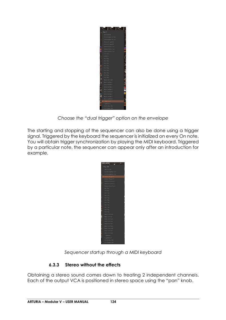
ARTURIA – Modular V – USER MANUAL 124
Choose the “dual trigger” option on the envelope
The starting and stopping of the sequencer can also be done using a trigger
signal. Triggered by the keyboard the sequencer is initialized on every On note.
You will obtain trigger synchronization by playing the MIDI keyboard. Triggered
by a particular note, the sequencer can appear only after an introduction for
example.
Sequencer startup through a MIDI keyboard
6.3.3 Stereo without the effects
Obtaining a stereo sound comes down to treating 2 independent channels.
Each of the output VCA is positioned in stereo space using the “pan” knob.

ARTURIA – Modular V – USER MANUAL 125
Set the VCA1 “pan” to the left, and the VCA2 to the right to create 2
independent channels needed for convincing stereo.
Setting the output VCA panoramic
Connecting a different oscillator to each of the VCA allows you to obtain a
very wide space. To make it evolve, apply a light detuning to one of the
oscillators using a LFO or an envelope. The sound will seem like it’s turning in
space, or in the second case, passing from one point to another.
To keep the stereo space very wide, it is essential to keep the 2 channels
independent. Il It is thus necessary to use a filter for each of them. These filters
can then be modulated in an identical manner, or differently without
interfering with the stereo space.
For a right to left movement, you can also modulate the output VCA with an
auxiliary envelope, once connected, set the modulation level to a positive
value for one and negative for the other.
Connection of an auxiliary envelope for the output VCA

ARTURIA – Modular V – USER MANUAL 126
These patches, you will have noticed have very different levels of difficulty. We
hope that they will have allowed you to see some of the possibilities that the
Modular V has to offer. But don’t hesitate in testing the programming yourself,
this is how we learn and progress and develop more originality.
6.3.4 The Bode Frequency Shifter
The Bode Frequency Shifter was certainly one of the most coveted modules
while at the same time one of the least known in the Bob Moog’s modular
galaxy. There were around 10 sold across the world.
The bode Shifter module
It allows the creation of a huge number of unique sounds, which we will see, in
the two following examples:
6.3.4.1 More stereo width
Obtain more stereo width by slightly dephasing the pitch of the sound. Take as
an example the preset “Bode_Bass” (in the “Factory” bank).
For this very simple preset, we will use an oscillator where the “sawtooth” signal
will be directed straight to the Bode Frequency Shifter audio in.
The A and B outputs on the Bode Frequency Shifter are directed towards the
inputs for VCA1 and 2. The panoramic knobs are turned to the left for VCA1
and to the right for VCA2 to obtain a stereo sound.
The main tuning frequency on the Bode Shifter is placed at 0.000 Hz (“amount
of shift” knob centered). The “Scale” setting is placed to position “5” (the
variations in height are very weak). Also, leave the “Mixture” setting at the
center (it won’t be used in this example)

ARTURIA – Modular V – USER MANUAL 127
A slow modulation is applied to the Bode Shifter frequency thanks to the sine
signal of a LFO.
The modulation phase being inverted on outputs A and B, you obtain a very
natural dephasing between the left and right signals.
This effect could be compared to a short reverberation effect if the modulation
rate is weak or “chorus” if we increase the modulation rate.
The “Bode-Bass” patch
6.3.4.2 Electronic percussion sequence
For this example we will use the sequencer to create a simple melody with the
Bode Shifter. Sequence lines 1 and 2 will modulate the height of the Bode
frequency (” Frequency shifter modulation”).
Take the preset “Sequences” > “Bode_Seq” in the “Factory” bank. The
composition of modules is about the same as the previous example. A low pass
24dB filter has been added to filter undesirable high-pitched harmonics as
output from the Bode Shifter.
The first two sequencer lines modulate two Bode Shifter modulation inputs (the
first at a value of 0.3247 and the second at – 0.4588). The two sequences
complement one another setting the “amount of shift” parameter.

ARTURIA – Modular V – USER MANUAL 128
The Bode Shifter possesses a sound close to a Ring Modulator; the resulting
sound is slightly metallic. We can direct the signal to a low pass filter (LP filter 24
dB) to dampen certain high frequencies.
It is also possible to use a waveform that is not as rich in harmonics on the
oscillator (the triangle, for example) if we don’t want to filter the sound coming
from the Bode Shifter.
The “Bode_Seq” patch
We are not obliged to use a sequencer as source of frequency modulation for
the Bode Shifter. More subtle modifications are also possible with a LFO or a
key follow.
6.3.5 The Envelope Follower
The envelope follower is a module favored by aficionados of modular
synthesizers with the goal of modulating the envelope with an external signal.
(A drum line is very appropriate for this type of use.) The result: obtain a
complex envelope following the evolution of an audio signal.

ARTURIA – Modular V – USER MANUAL 129
It is also possible to connect any other source of modulation to the envelope
follow input: An envelope for example. The course of the latter can be
modified with the envelope follower parameters.
The “envelope follower” module
Let’s have a closer look at these two situations:
6.3.5.1 Trig by an external audio source.
In the first case, the Modular V will be used as a VST insert effect for an audio
track in Cubase SX.
If you don’t have Cubase, know that the procedure remains globally the same
for any other sequencer.
Firstly, place a sample (preferably a drum loop) on an audio track on the
sequencer.
Open a VST “Insert” effect on this track by choosing “Modular V2 FX”.
On a MIDI track, choose the Modular V2 FX as MIDI control output. It will thus
be controlled by your master keyboard or by a sequence recorded in the
arrangement. This point is essential for generating the sound of the Modular V.
It is also possible to create a continuous note (hold) so that the Modular
signal doesn’t stop. For this, set the “Release” knob on the VCA1 envelope fully
to the right (in the direction of the hands of a clock).
On the Modular, choose the “EFX/ Ext_In” preset in the “Factory” bank. The “Ext
Left” audio in (on the lower section) is connected to the envelope follower
audio in. This indicates that the audio signal will guide the envelope.
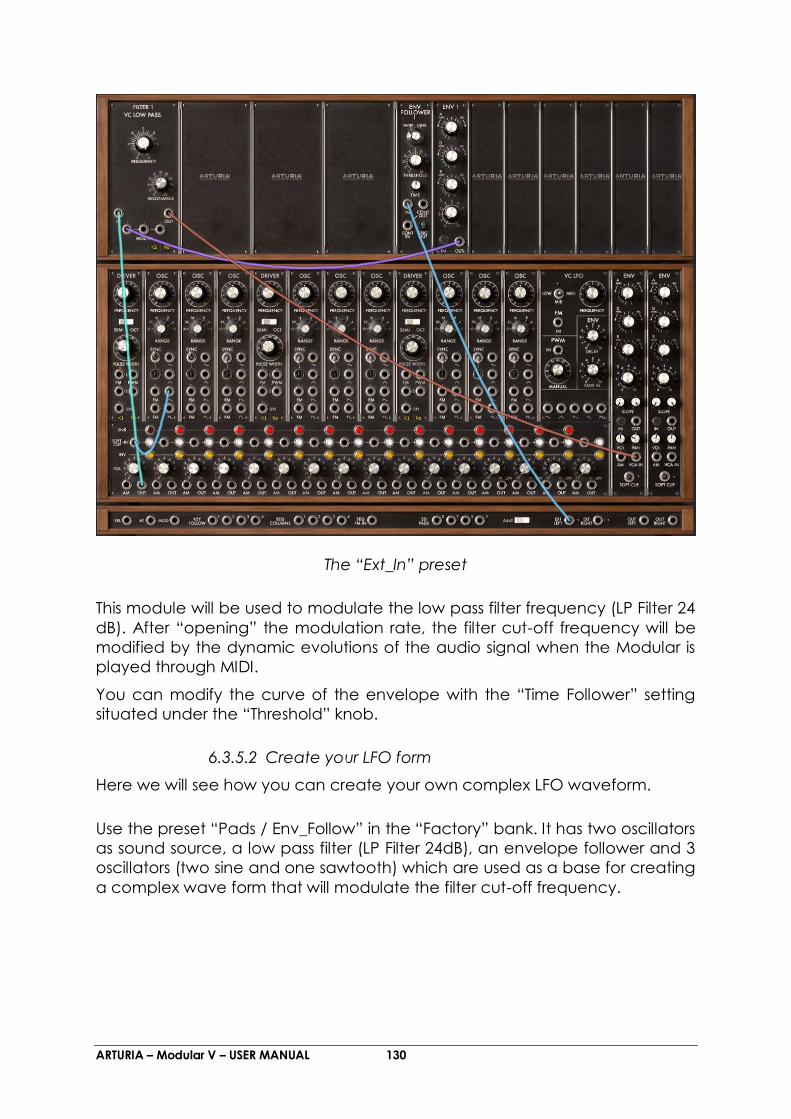
ARTURIA – Modular V – USER MANUAL 130
The “Ext_In” preset
This module will be used to modulate the low pass filter frequency (LP Filter 24
dB). After “opening” the modulation rate, the filter cut-off frequency will be
modified by the dynamic evolutions of the audio signal when the Modular is
played through MIDI.
You can modify the curve of the envelope with the “Time Follower” setting
situated under the “Threshold” knob.
6.3.5.2 Create your LFO form
Here we will see how you can create your own complex LFO waveform.
Use the preset “Pads / Env_Follow” in the “Factory” bank. It has two oscillators
as sound source, a low pass filter (LP Filter 24dB), an envelope follower and 3
oscillators (two sine and one sawtooth) which are used as a base for creating
a complex wave form that will modulate the filter cut-off frequency.
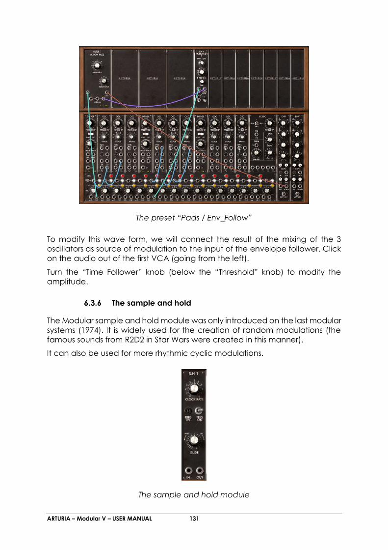
ARTURIA – Modular V – USER MANUAL 131
The preset “Pads / Env_Follow”
To modify this wave form, we will connect the result of the mixing of the 3
oscillators as source of modulation to the input of the envelope follower. Click
on the audio out of the first VCA (going from the left).
Turn the “Time Follower” knob (below the “Threshold” knob) to modify the
amplitude.
6.3.6 The sample and hold
The Modular sample and hold module was only introduced on the last modular
systems (1974). It is widely used for the creation of random modulations (the
famous sounds from R2D2 in Star Wars were created in this manner).
It can also be used for more rhythmic cyclic modulations.
The sample and hold module

ARTURIA – Modular V – USER MANUAL 132
Here we will look at creating a random modulation.
Use the “Pads / Slow_SH” preset from the “Factory” bank for this example. It is
made up of 3 oscillators, a low pass filter (LP Filter 24dB), a noise module and a
Sample and Hold.
The “Slow_SH_Pad” preset
The pink noise output is filtered by a low pass filter (6 dB/oct) and directed to
the sample & hold audio in. The audio out of the latter is connected to one of
the 3 cut-off frequency modulation inputs of the low pass filter.
The result is random changes to the filter cut-off frequency.
Now set the modulation rate by turning the “Clock rate” knob on the
Sample and Hold module.
o By setting the filter cut-off frequency on the “Noise” module, the
high-pitched frequencies will be filtered. The variations in
modulation will be “softened” in this manner.
By using the “Glide” knob on the “Sample and Hold” module, these
modulation If you want to soften these variations there are two solutions:
o variations will be smoother.
The new modules included with the Modular V 2.0 will add a large number of
editing possibilities. They were difficult to create (impossible in some cases)
before. Don’t hesitate to experiment in new editing methods.

ARTURIA – Modular V – USER MANUAL 133
7 END USER LICENSE AGREEMENT
1. General
1.1 In consideration of payment of the Licensee fee, which is a portion of the
price you paid, Arturia, as Licensor, grants to you (hereinafter termed
“Licensee”) a nonexclusive right for the use of software including related
media, documentation (for example program descriptions, manuals) and
other documents and materials manufactured by Arturia SA ("Product(s)").
All intellectual property rights in the software belong to Arturia SA (hereinafter:
“Arturia”).
1.2 The following editions of the Product are available: “Demo”, “Standard”,
“EDU” and “NFR”. Whilst each edition equips the User with the same software,
the editions vary as regards both the scope of functions activated in the
Product, and the rights of use granted under this EULA.
1.3 By installing the software on your computer you agree to these terms and
conditions. If you do not approve these terms and conditions, you must not
install this software.
1.4 If you do not approve these terms and conditions, please return the
complete Product (including all written matter, packaging and similar
material) to the dealer from whom it was originally bought within 14 (fourteen)
days after the day of purchase. For purchases from the Arturia Online Store,
please contact Arturia on the internet website:
www.arturia.com/support/askforhelp/purchase.
1.5 Arturia reserves all rights not expressly granted in the EULA.
2. Right of use
2.1 The Product is protected by copyright. The Licensee may not lease, loan or
sub-license the software. The Licensee is not authorized to modify the software.
2.2 Owning any product provided to the Licensee as “Standard” version grants the
Licensee a non-exclusive right to use the Product in perpetuity including
commercial purposes. The Licensee can activate the Product on up to five
computers, as long as only one installation is used at any given time. The
Licensee must register the Product to Arturia to get access to client support,
and to activate his Product. (An internet connection is required to register and
activate the Product, either on the computer on which the Product is installed,
either on another device able to exchange files with the computer on which
the Product is installed). Owning a license of the Products entitles the Licensee
to get access to the future updates of this Product.
2.3 Any Products provided to you as "NFR" (Not For Resale) version grants the
Licensee a non-exclusive right to use the Product for a limited period of time.
The Product shall only be used for demonstration, testing and evaluation
purposes. NFR Products must not be used for commercial purposes, and must

ARTURIA – Modular V – USER MANUAL 134
not be resold or transferred. The Licensee can activate the Product on up to
five computers, as long as only one installation is used at any given time. The
Licensee must register the Product to Arturia to get access to client support,
and to activate his Product. (An internet connection is required to register and
activate the Product, either on the computer on which the Product is installed,
either on another device able to exchange files with the computer on which
the Product is installed). NFR Products are exempt from update, upgrade or
crossgrade offers, and cannot be purchased with or exchanged for vouchers
or coupons. Furthermore, as an owner of a NFR Product, you are not entitled
to any vouchers that ship with the standard version of the Product.
2.4 Any Products labelled or otherwise provided to you as an “Educational”
version grants the Licensee a non-exclusive right to use the Product in
perpetuity. The Product shall only be used by students or those working in
educational institutions. This definition includes students, faculty, staff and
administration attending and / or working at an educational institutional
facility: private / public schools, colleges, universities and similar. These
Products must not be used for commercial purposes, and must not be resold
or transferred. The Licensee can activate the Product on up to five computers,
as long as only one installation is used at any given time. The Licensee must
register the Product to Arturia to get access to client support, and to activate
his Product. (An internet connection is required to register and activate the
Product, either on the computer on which the Product is installed, either on
another device able to exchange files with the computer on which the
Product is installed). These Products are exempt from upgrade or crossgrade
offers, and cannot be purchased with or exchanged for vouchers or coupons.
Furthermore, as an owner of an educational Product, you are not entitled to
any vouchers that ship with the standard version of the Product.
2.5 Any Products labelled or otherwise provided to you as a “Demo” version
grants the Licensee a right to use the Product only for demonstration and
evaluation purposes. These Products must not be used for commercial
purposes, and must not be resold or transferred. These Products are exempt
from upgrade or crossgrade offers, and cannot be exchanged for vouchers or
coupons.
3. No Unbundling
Bundles (product bundles are an association of software and hardware or
software-only products) can only be resold / transferred as a whole. The
individual components of a bundle must not be resold / transferred separately.
4. Resell
4.1 Renting or lending the licensed Software to a third party is expressly
forbidden. Apart from that and if not provided otherwise within this EULA.
4.2 Except if otherwise stated within this EULA, Licensee may resell the software
to a third party or transfer the software permanently free of charge, provided
ARTURIA – Modular V – USER MANUAL 135
the third party agrees in writing with this EULA and Licensee ceases all use of
the software, completely removes all installed copies of the software from his
computers and – if the software was not purchased via download – deletes or
transfers the original media delivered with the software to the third party. In
addition, Licensee is required to de-register the purchased software with
Arturia (more information available on www.arturia.com).
5. In case a sound library is part of the purchased Product the following shall
apply in addition to the EULA
The provided samples, instruments and presets can be used for commercial or
non-commercial music and audio Productions without the prior permission
from Arturia under the terms of this Agreement. The usage of this Product (in
particular samples, instruments and presets) for the creation of a sound library
or as a sound library for any kind of synthesizer, virtual instrument, sample library,
sample-based Product or other musical instrument is strictly prohibited.
Individual samples, sound sets or audio loops may not be distributed
(commercially or otherwise) standalone. Furthermore these samples, sound
sets or audio may not be repackaged in whole or in part as audio samples,
sound libraries or sound effects.
6. Data Protection
Arturia attaches great importance to compliance with legislation on data
protection. The User data collected are used exclusively for performing its
contractual obligations. No data is passed on to third parties. Further
information can be obtained from our Privacy Policy at
www.arturia.com/privacy.
7. Limited Warranty
Arturia warrants that the physical media on which the software is provided is
free from defects in materials and workmanship under normal use for a period
of thirty (30) days from the date of purchase. The Licensee’s invoice shall be
evidence of the date of purchase. Any implied warranties on the software are
limited to thirty (30) days from the date of purchase. Some states do not allow
limitations on duration of an implied warranty, so the above limitation may not
apply to the Licensee in this case. All programs and accompanying materials
are provided “as is”.
8. No Liability for Consequential Damages
Neither Arturia nor anyone else involved in the creation, production, or delivery
of this Product shall be liable for any direct, indirect, consequential, or
incidental damages arising out of the use of, or inability to use this Product
(including without limitation, damages for loss of business profits, business
interruption, loss of business information and the like) even if Arturia was

ARTURIA – Modular V – USER MANUAL 136
previously advised of the possibility of such damages. Some states do not allow
limitations on the length of an implied warranty or the exclusion or limitation of
incidental or consequential damages, so the above limitation or exclusions
may not apply to the Licensee in this case. This warranty gives the Licensee
specific legal rights, and the Licensee may also have other rights which vary
from state to state.