user manual: model 1700 transmitters with analog outputs · configuration and use manual...
TRANSCRIPT

Configuration and Use ManualMMI-20019028, Rev AB
March 2018
Micro Motion® Model 1700 Transmitters withAnalog Outputs
Configuration and Use Manual

Safety messages
Safety messages are provided throughout this manual to protect personnel and equipment. Read each safety message carefullybefore proceeding to the next step.
Other information
Full product specifications can be found in the product data sheet. Troubleshooting information can be found in the configurationmanual. Product data sheets and manuals are available from the Micro Motion web site at www.emerson.com.
Return policy
Follow Micro Motion procedures when returning equipment. These procedures ensure legal compliance with governmenttransportation agencies and help provide a safe working environment for Micro Motion employees. Micro Motion will not acceptyour returned equipment if you fail to follow Micro Motion procedures.
Return procedures and forms are available on our web support site at www.emerson.com, or by phoning the Micro Motion CustomerService department.
Emerson Flow customer service
Email:
• Worldwide: [email protected]
• Asia-Pacific: [email protected]
Telephone:
North and South America Europe and Middle East Asia Pacific
United States 800-522-6277 U.K. 0870 240 1978 Australia 800 158 727
Canada +1 303-527-5200 The Netherlands +31 (0) 704 136 666 New Zealand 099 128 804
Mexico +41 (0) 41 7686 111 France 0800 917 901 India 800 440 1468
Argentina +54 11 4837 7000 Germany 0800 182 5347 Pakistan 888 550 2682
Brazil +55 15 3413 8000 Italy 8008 77334 China +86 21 2892 9000
Central & Eastern +41 (0) 41 7686 111 Japan +81 3 5769 6803
Russia/CIS +7 495 981 9811 South Korea +82 2 3438 4600
Egypt 0800 000 0015 Singapore +65 6 777 8211
Oman 800 70101 Thailand 001 800 441 6426
Qatar 431 0044 Malaysia 800 814 008
Kuwait 663 299 01
South Africa 800 991 390
Saudi Arabia 800 844 9564
UAE 800 0444 0684
Contents
Part I Getting startedChapter 1 Before you begin ............................................................................................................. 3
1.1 About this manual ......................................................................................................................... 31.2 Transmitter model code ................................................................................................................ 31.3 Communications tools and protocols ............................................................................................ 41.4 Additional documentation and resources ...................................................................................... 4
Chapter 2 Quick start .......................................................................................................................52.1 Power up the transmitter ...............................................................................................................52.2 Check meter status ........................................................................................................................6
2.2.1 Transmitter status reported by LED .................................................................................62.3 Make a startup connection to the transmitter ................................................................................72.4 (Optional) Adjust digital communications settings ........................................................................ 72.5 Verify mass flow measurement ......................................................................................................72.6 Verify the zero ............................................................................................................................... 8
2.6.1 Terminology used with zero verification and zero calibration .......................................... 9
Part II Configuration and commissioningChapter 3 Introduction to configuration and commissioning ......................................................... 13
3.1 Configuration flowchart .............................................................................................................. 133.2 Default values and ranges ............................................................................................................153.3 Enable access to the off-line menu of the display ......................................................................... 153.4 Disable write-protection on the transmitter configuration .......................................................... 153.5 Restore the factory configuration ................................................................................................ 16
Chapter 4 Configure process measurement ................................................................................... 174.1 Configure mass flow measurement ............................................................................................. 17
4.1.1 Configure Mass Flow Measurement Unit ...................................................................... 174.1.2 Configure Flow Damping ..............................................................................................204.1.3 Configure Mass Flow Cutoff ..........................................................................................21
4.2 Configure volume flow measurement for liquid applications ....................................................... 224.2.1 Configure Volume Flow Type for liquid applications ......................................................234.2.2 Configure Volume Flow Measurement Unit for liquid applications ................................ 234.2.3 Configure Volume Flow Cutoff ..................................................................................... 26
4.3 Configure GSV flow measurement ...............................................................................................274.3.1 Configure Volume Flow Type for gas applications ......................................................... 284.3.2 Configure Standard Density of Gas ...............................................................................284.3.3 Configure Gas Standard Volume Flow Unit ................................................................... 304.3.4 Configure Gas Standard Volume Flow Cutoff ................................................................33
4.4 Configure Flow Direction ............................................................................................................ 344.4.1 Options for Flow Direction ........................................................................................... 35
4.5 Configure density measurement .................................................................................................394.5.1 Configure Density Measurement Unit .......................................................................... 39
Contents
Configuration and Use Manual i
4.5.2 Configure two-phase flow parameters .......................................................................... 404.5.3 Configure Density Damping ......................................................................................... 424.5.4 Configure Density Cutoff ..............................................................................................43
4.6 Configure temperature measurement .........................................................................................444.6.1 Configure Temperature Measurement Unit ..................................................................444.6.2 Configure Temperature Damping ................................................................................ 444.6.3 Effect of Temperature Damping on process measurement ........................................... 454.6.4 Configure Temperature Input ...................................................................................... 45
4.7 Configure pressure compensation ...............................................................................................464.7.1 Configure pressure compensation using ProLink III ...................................................... 464.7.2 Configure pressure compensation using the Field Communicator ................................474.7.3 Options for Pressure Measurement Unit .......................................................................49
Chapter 5 Configure device options and preferences ..................................................................... 515.1 Configure the transmitter display ................................................................................................ 51
5.1.1 Configure the language used for the display ................................................................. 515.1.2 Configure the process variables and diagnostic variables shown on the display .............515.1.3 Configure the number of decimal places (precision) shown on the display ....................535.1.4 Configure the refresh rate of data shown on the display ................................................545.1.5 Enable or disable automatic scrolling through the display variables .............................. 545.1.6 Enable or disable the display backlight .......................................................................... 555.1.7 Enable or disable Status LED Blinking ............................................................................55
5.2 Enable or disable operator actions from the display ..................................................................... 565.2.1 Enable or disable Totalizer Start/Stop from the display ..................................................565.2.2 Enable or disable Totalizer Reset from the display ......................................................... 575.2.3 Enable or disable the Acknowledge All Alerts display command ....................................57
5.3 Configure security for the display menus ..................................................................................... 585.4 Configure response time parameters .......................................................................................... 59
5.4.1 Configure Update Rate .................................................................................................605.4.2 Configure Response Time ............................................................................................. 61
5.5 Configure alert handling ..............................................................................................................625.5.1 Configure Fault Timeout .............................................................................................. 625.5.2 Configure Status Alert Severity .....................................................................................63
5.6 Configure informational parameters ........................................................................................... 675.6.1 Configure Sensor Serial Number ...................................................................................675.6.2 Configure Sensor Material ............................................................................................ 675.6.3 Configure Sensor Liner Material ....................................................................................685.6.4 Configure Sensor Flange Type ...................................................................................... 685.6.5 Configure Descriptor ....................................................................................................695.6.6 Configure Message ...................................................................................................... 695.6.7 Configure Date .............................................................................................................69
Chapter 6 Integrate the meter with the control system ..................................................................716.1 Configure the transmitter channels ............................................................................................. 716.2 Configure the mA Output ............................................................................................................ 72
6.2.1 Configure mA Output Process Variable ........................................................................ 726.2.2 Configure Lower Range Value (LRV) and Upper Range Value (URV) ...............................746.2.3 Configure AO Cutoff .....................................................................................................756.2.4 Configure Added Damping ...........................................................................................776.2.5 Configure mA Output Fault Action and mA Output Fault Level ..................................... 78
6.3 Configure the Frequency Output ................................................................................................. 796.3.1 Configure Frequency Output Polarity ........................................................................... 80
Contents
ii Micro Motion Model 1700 Transmitters with Analog Outputs

6.3.2 Configure Frequency Output Scaling Method ...............................................................816.3.3 Configure Frequency Output Fault Action and Frequency Output Fault Level ............... 82
6.4 Configure the Discrete Output .................................................................................................... 836.4.1 Configure Discrete Output Source ............................................................................... 846.4.2 Configure Discrete Output Polarity .............................................................................. 866.4.3 Configure Discrete Output Fault Action ........................................................................86
6.5 Configure events ......................................................................................................................... 876.5.1 Configure a basic event .................................................................................................886.5.2 Configure an enhanced event ....................................................................................... 88
6.6 Configure digital communications .............................................................................................. 906.6.1 Configure HART/Bell 202 communications .................................................................. 906.6.2 Configure HART/RS-485 communications .................................................................... 956.6.3 Configure Modbus/RS-485 communications ................................................................ 966.6.4 Configure Digital Communications Fault Action ...........................................................98
Chapter 7 Complete the configuration .........................................................................................1017.1 Test or tune the system using sensor simulation ........................................................................101
7.1.1 Sensor simulation ....................................................................................................... 1027.2 Back up transmitter configuration ............................................................................................. 1037.3 Enable write-protection on the transmitter configuration ......................................................... 103
Part III Operations, maintenance, and troubleshootingChapter 8 Transmitter operation ................................................................................................. 107
8.1 Record the process variables ..................................................................................................... 1078.2 View process variables ...............................................................................................................108
8.2.1 View process variables using the display .....................................................................1088.2.2 View process variables and other data using ProLink III ...............................................1098.2.3 View process variables using the Field Communicator ................................................109
8.3 View transmitter status using the status LED ............................................................................. 1108.4 View and acknowledge status alerts .......................................................................................... 111
8.4.1 View and acknowledge alerts using the display .......................................................... 1118.4.2 View and acknowledge alerts using ProLink III ............................................................ 1138.4.3 View alerts using the Field Communicator ................................................................. 114
8.5 Read totalizer and inventory values ........................................................................................... 1148.6 Start and stop totalizers and inventories ....................................................................................114
8.6.1 Start and stop totalizers and inventories using the display ..........................................1158.7 Reset totalizers ..........................................................................................................................116
8.7.1 Reset totalizers using the display ................................................................................1168.8 Reset inventories .......................................................................................................................118
Chapter 9 Measurement support ................................................................................................. 1199.1 Options for measurement support ............................................................................................ 1199.2 Use Smart Meter Verification (SMV) .......................................................................................... 120
9.2.1 SMV requirements ...................................................................................................... 1209.2.2 SMV test preparation .................................................................................................. 1209.2.3 Run SMV ..................................................................................................................... 1219.2.4 View test data ............................................................................................................. 1259.2.5 Schedule automatic execution of the SMV test ........................................................... 129
9.3 Use PVR, TBR, and TMR ..............................................................................................................1329.3.1 PVR, TBR, and TMR applications .................................................................................. 133
9.4 Piecewise linearization (PWL) for calibrating gas meters ............................................................134
Contents
Configuration and Use Manual iii
9.5 Zero the meter .......................................................................................................................... 1349.6 Validate the meter .....................................................................................................................135
9.6.1 Alternate method for calculating the meter factor for volume flow .............................1369.7 Perform a (standard) D1 and D2 density calibration ...................................................................137
9.7.1 Perform a D1 and D2 density calibration using ProLink III ............................................ 1389.7.2 Perform a D1 and D2 density calibration using the Field Communicator ..................... 139
9.8 Perform a D3 and D4 density calibration (T-Series sensors only) ................................................ 1409.8.1 Perform a D3 or D3 and D4 density calibration using ProLink III .................................. 1409.8.2 Perform a D3 or D3 and D4 density calibration using the Field Communicator ........... 141
9.9 Perform temperature calibration ............................................................................................... 1429.9.1 Perform temperature calibration using the display ..................................................... 1439.9.2 Perform temperature calibration using ProLink III .......................................................1439.9.3 Perform temperature calibration using the Field Communicator ................................145
Chapter 10 Troubleshooting .......................................................................................................... 14710.1 Status LED states ....................................................................................................................... 14810.2 Status alerts, causes, and recommendations ............................................................................. 14810.3 Flow measurement problems ................................................................................................... 15910.4 Density measurement problems ............................................................................................... 16110.5 Temperature measurement problems .......................................................................................16210.6 Milliamp output problems ......................................................................................................... 16310.7 Frequency Output problems ......................................................................................................16410.8 Using sensor simulation for troubleshooting ............................................................................. 16510.9 Check power supply wiring ........................................................................................................16510.10 Check sensor-to-transmitter wiring ........................................................................................... 16610.11 Check grounding ....................................................................................................................... 16710.12 Perform loop tests ..................................................................................................................... 167
10.12.1 Perform loop tests using the display ...........................................................................16710.12.2 Perform loop tests using ProLink III .............................................................................16910.12.3 Perform loop tests using the Field Communicator ......................................................170
10.13 Check the HART communication loop ....................................................................................... 17110.14 Check HART Address and mA Output Action ............................................................................. 17210.15 Check HART burst mode ............................................................................................................17310.16 Check the trimming of the mA Output ...................................................................................... 17310.17 Check Lower Range Value and Upper Range Value ....................................................................17310.18 Check mA Output Fault Action ..................................................................................................17310.19 Check for radio frequency interference (RFI) ..............................................................................17410.20 Check Frequency Output Scaling Method ................................................................................. 17410.21 Check Frequency Output Fault Action .......................................................................................17410.22 Check Flow Direction ................................................................................................................ 17510.23 Check the cutoffs ...................................................................................................................... 17510.24 Check for two-phase flow (slug flow) ......................................................................................... 17510.25 Check the drive gain .................................................................................................................. 176
10.25.1 Collect drive gain data ................................................................................................ 17710.26 Check the pickoff voltage .......................................................................................................... 177
10.26.1 Collect pickoff voltage data ........................................................................................ 17810.27 Check for internal electrical problems ....................................................................................... 178
10.27.1 Check the sensor coils .................................................................................................17910.28 Check the core processor LED ....................................................................................................181
10.28.1 Core processor LED states ........................................................................................... 18410.29 Perform a 700 core processor resistance test .............................................................................186
Contents
iv Micro Motion Model 1700 Transmitters with Analog Outputs

Appendices and referenceAppendix A Using the transmitter display .......................................................................................189
A.1 Components of the transmitter interface .................................................................................. 189A.2 Use the optical switches ............................................................................................................ 190A.3 Access and use the display menu system ................................................................................... 191
A.3.1 Enter a floating-point value using the display .............................................................. 192A.4 Display codes for process variables ............................................................................................ 195A.5 Codes and abbreviations used in display menus ........................................................................ 196
Appendix B Using ProLink III with the transmitter ...........................................................................201B.1 Basic information about ProLink III ............................................................................................ 201B.2 Connect with ProLink III ............................................................................................................ 202
B.2.1 Connection types supported by ProLink III ..................................................................202B.2.2 Connect with ProLink III to the service port ................................................................. 203B.2.3 Make a HART/Bell 202 connection .............................................................................. 204B.2.4 Make a HART/RS-485 connection ................................................................................209B.2.5 Connect with ProLink III to the RS-485 port ................................................................. 212
Appendix C Using a Field Communicator with the transmitter ........................................................ 217C.1 Basic information about the Field Communicator ..................................................................... 217C.2 Connect with the Field Communicator ..................................................................................... 218
Appendix D Default values and ranges ............................................................................................ 221D.1 Default values and ranges ..........................................................................................................221
Appendix E Transmitter components and installation wiring ......................................................... 227E.1 Installation types ....................................................................................................................... 227E.2 Power supply terminals and ground ..........................................................................................230E.3 Input/output (I/O) wiring terminals ........................................................................................... 231
Appendix F NE 53 history ............................................................................................................... 233F.1 NE 53 history ............................................................................................................................. 233
Contents
Configuration and Use Manual v

Contents
vi Micro Motion Model 1700 Transmitters with Analog Outputs

Part IGetting started
Chapters covered in this part:
• Before you begin
• Quick start
Getting started
Configuration and Use Manual 1

Getting started
2 Micro Motion Model 1700 Transmitters with Analog Outputs
1 Before you beginTopics covered in this chapter:
• About this manual
• Transmitter model code
• Communications tools and protocols
• Additional documentation and resources
1.1 About this manualThis manual helps you configure, commission, use, maintain, and troubleshootMicro Motion Model 1700 transmitters with analog outputs.
ImportantThis manual assumes that the following conditions apply:
• The transmitter has been installed correctly and completely according to the instructions inthe transmitter installation manual
• The installation complies with all applicable safety requirements
• The user is trained in local and corporate safety standards
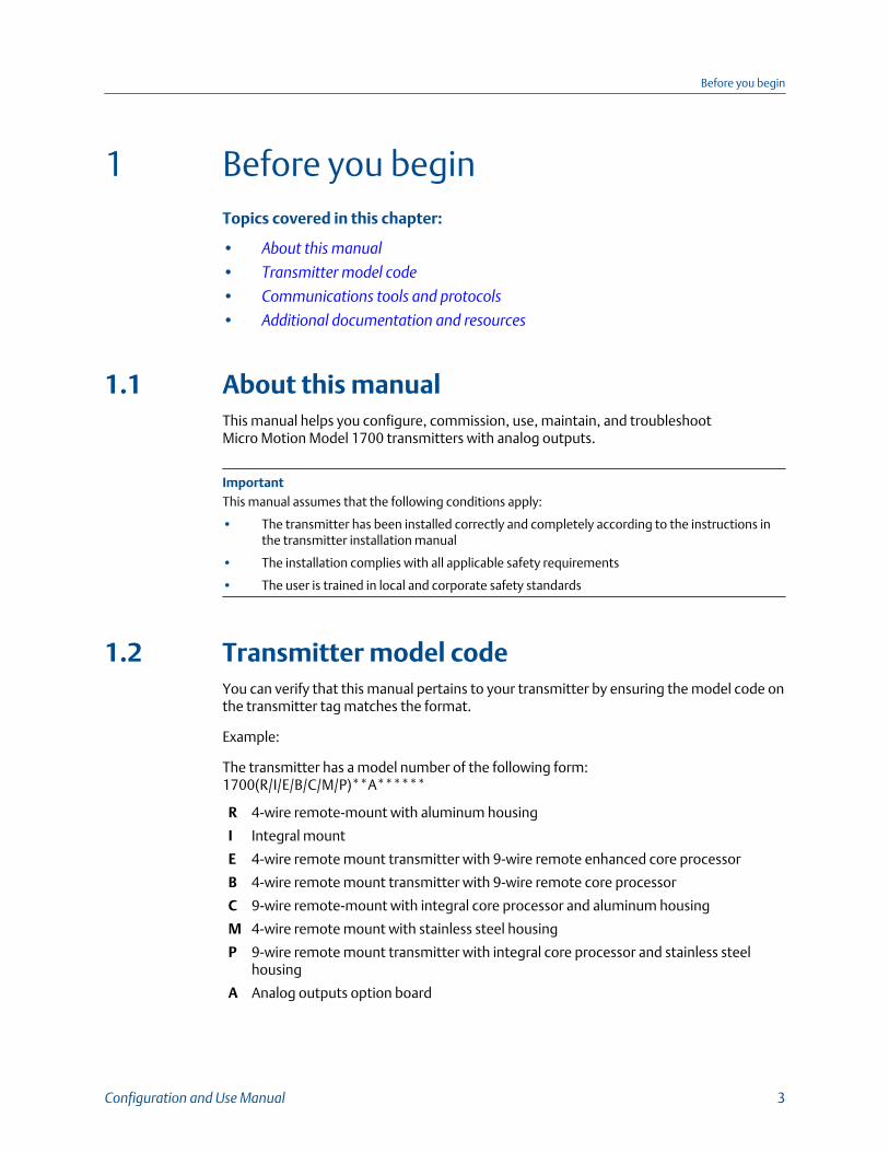
1.2 Transmitter model codeYou can verify that this manual pertains to your transmitter by ensuring the model code onthe transmitter tag matches the format.
Example:
The transmitter has a model number of the following form:1700(R/I/E/B/C/M/P)**A******
R 4-wire remote-mount with aluminum housing
I Integral mount
E 4-wire remote mount transmitter with 9-wire remote enhanced core processor
B 4-wire remote mount transmitter with 9-wire remote core processor
C 9-wire remote-mount with integral core processor and aluminum housing
M 4-wire remote mount with stainless steel housing
P 9-wire remote mount transmitter with integral core processor and stainless steelhousing
A Analog outputs option board
Before you begin
Configuration and Use Manual 3

1.3 Communications tools and protocolsYou can use several different communications tools and protocols to interface with thetransmitter, use different tools in different locations, or use different tools for differenttasks.
Tool Supported protocols
ProLink III • HART/RS-485• HART/Bell 202• Modbus/RS-485• Service port
Field Communicator HART/Bell 202
For information about how to use the communication tools, see the appendices in thismanual.
TipYou may be able to use other communications tools, such as AMS Suite: Intelligent Device Manager,or the Smart Wireless THUM™ Adapter. Use of AMS or the Smart Wireless THUM Adapter is notdiscussed in this manual. For more information on the Smart Wireless THUM Adapter, refer to thedocumentation available at www.emerson.com.
1.4 Additional documentation and resources
Topic Document
Hazardous area installa-tion
See the approval documentation shipped with the transmitter, ordownload the appropriate documentation at www.emerson.com.
Product Data Sheet Micro Motion Series 1000 and Series 2000 Transmitters with MVD™ Tech‐nology Product Data Sheet
Sensor Sensor documentation
Transmitter installation Micro Motion® Model 1700 and 2700 Installation Manual
All documentation resources are available at www.emerson.com or on the userdocumentation DVD.
Before you begin
4 Micro Motion Model 1700 Transmitters with Analog Outputs
2 Quick startTopics covered in this chapter:
• Power up the transmitter
• Check meter status
• Make a startup connection to the transmitter
• (Optional) Adjust digital communications settings
• Verify mass flow measurement
• Verify the zero
2.1 Power up the transmitterThe transmitter must be powered up for all configuration and commissioning tasks, or forprocess measurement.
1. Ensure that all transmitter and sensor covers and seals are closed.
DANGER!
To prevent ignition of flammable or combustible atmospheres, ensure that all coversand seals are tightly closed. For hazardous area installations, applying power whilehousing covers are removed or loose can cause an explosion.
2. Turn on the electrical power at the power supply.
The transmitter will automatically perform diagnostic routines. The transmitter isself-switching and will automatically detect the supply voltage. When using DCpower, a minimum of 1.5 amps of startup current is required. During this period,Alert 009 is active. The diagnostic routines should complete in approximately30 seconds. For transmitters with a display, the status LED will turn green and beginto flash when the startup diagnostics are complete. If the status LED exhibitsdifferent behavior, an alert is active.
Postrequisites
Although the sensor is ready to receive process fluid shortly after power-up, the electronicscan take up to 10 minutes to reach thermal equilibrium. Therefore, if this is the initialstartup, or if power has been off long enough to allow components to reach ambienttemperature, allow the electronics to warm up for approximately 10 minutes beforerelying on process measurements. During this warm-up period, you may observe minormeasurement instability or inaccuracy.
Quick start
Configuration and Use Manual 5
2.2 Check meter statusCheck the meter for any error conditions that require user action or that affectmeasurement accuracy.
1. Wait approximately 10 seconds for the power-up sequence to complete.
Immediately after power-up, the transmitter runs through diagnostic routines andchecks for error conditions. During the power-up sequence, Alert A009 is active.This alert should clear automatically when the power-up sequence is complete.
2. Check the status LED on the transmitter.
Related information
View and acknowledge status alerts
2.2.1 Transmitter status reported by LED
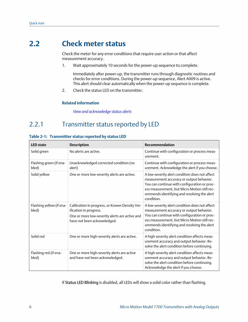
Transmitter status reported by status LEDTable 2-1:
LED state Description Recommendation
Solid green No alerts are active. Continue with configuration or process meas-urement.
Flashing green (if ena-bled)
Unacknowledged corrected condition (noalert)
Continue with configuration or process meas-urement. Acknowledge the alert if you choose.
Solid yellow One or more low-severity alerts are active. A low-severity alert condition does not affectmeasurement accuracy or output behavior.You can continue with configuration or proc-ess measurement, but Micro Motion still rec-ommends identifying and resolving the alertcondition.
Flashing yellow (if ena-bled)
Calibration in progress, or Known Density Ver-ification in progress.
One or more low-severity alerts are active andhave not been acknowledged.
A low-severity alert condition does not affectmeasurement accuracy or output behavior.You can continue with configuration or proc-ess measurement, but Micro Motion still rec-ommends identifying and resolving the alertcondition.
Solid red One or more high-severity alerts are active. A high-severity alert condition affects meas-urement accuracy and output behavior. Re-solve the alert condition before continuing.
Flashing red (if ena-bled)
One or more high-severity alerts are activeand have not been acknowledged.
A high-severity alert condition affects meas-urement accuracy and output behavior. Re-solve the alert condition before continuing.Acknowledge the alert if you choose.
If Status LED Blinking is disabled, all LEDs will show a solid color rather than flashing.
Quick start
6 Micro Motion Model 1700 Transmitters with Analog Outputs

2.3 Make a startup connection to the transmitterFor all configuration tools except the display, you must have an active connection to thetransmitter to configure the transmitter. Follow this procedure to make your firstconnection to the transmitter.
Identify the connection type to use, and follow the instructions for that connection type inthe appropriate appendix. Use the default communications parameters shown in theappendix.
Communications tool Connection type to use Instructions
ProLink III HART/RS-485
Modbus/RS-485
Service port
Appendix B
Field Communicator HART/Bell 202 Appendix C
2.4 (Optional) Adjust digital communicationssettingsChange the communications parameters to site-specific values.
ImportantIf you are changing communications parameters for the connection type that you are using, you willlose the connection when you write the parameters to the transmitter. Reconnect using the newparameters.
Procedure
1. To change the communications parameters using ProLink III, choose Device Tools >Configuration > Communications.
2. To change the communications parameters using the Field Communicator, chooseOn-Line Menu > Configure > Manual Setup > Inputs/Outputs > Communications.
2.5 Verify mass flow measurementCheck to see that the mass flow rate reported by the transmitter is accurate. You can useany available method.
• Read the value for Mass Flow Rate on the transmitter display.
• Connect to the transmitter with ProLink III and read the value for Mass Flow Rate inthe Process Variables panel.
• Connect to the transmitter with the Field Communicator and read the value for MassFlow Rate.
Quick start
Configuration and Use Manual 7
On-Line Menu > Overview > Primary Purpose Variables
Postrequisites
If the reported mass flow rate is not accurate:
• Check the characterization parameters.
• Review the troubleshooting suggestions for flow measurement issues.
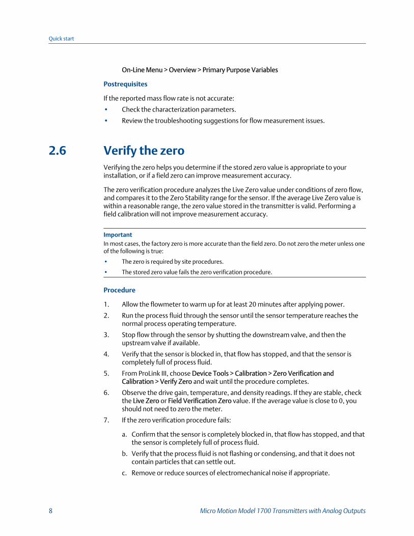
2.6 Verify the zeroVerifying the zero helps you determine if the stored zero value is appropriate to yourinstallation, or if a field zero can improve measurement accuracy.
The zero verification procedure analyzes the Live Zero value under conditions of zero flow,and compares it to the Zero Stability range for the sensor. If the average Live Zero value iswithin a reasonable range, the zero value stored in the transmitter is valid. Performing afield calibration will not improve measurement accuracy.
ImportantIn most cases, the factory zero is more accurate than the field zero. Do not zero the meter unless oneof the following is true:
• The zero is required by site procedures.
• The stored zero value fails the zero verification procedure.
Procedure
1. Allow the flowmeter to warm up for at least 20 minutes after applying power.
2. Run the process fluid through the sensor until the sensor temperature reaches thenormal process operating temperature.
3. Stop flow through the sensor by shutting the downstream valve, and then theupstream valve if available.
4. Verify that the sensor is blocked in, that flow has stopped, and that the sensor iscompletely full of process fluid.
5. From ProLink III, choose Device Tools > Calibration > Zero Verification andCalibration > Verify Zero and wait until the procedure completes.
6. Observe the drive gain, temperature, and density readings. If they are stable, checkthe Live Zero or Field Verification Zero value. If the average value is close to 0, youshould not need to zero the meter.
7. If the zero verification procedure fails:
a. Confirm that the sensor is completely blocked in, that flow has stopped, and thatthe sensor is completely full of process fluid.
b. Verify that the process fluid is not flashing or condensing, and that it does notcontain particles that can settle out.
c. Remove or reduce sources of electromechanical noise if appropriate.
Quick start
8 Micro Motion Model 1700 Transmitters with Analog Outputs

d. Repeat the zero verification procedure.
e. If it fails again, zero the meter.
Postrequisites
Restore normal flow through the sensor by opening the valves.
Related information
Zero the meter
2.6.1 Terminology used with zero verification and zerocalibration
Term Definition
Zero In general, the offset required to synchronize the left pickoff and the rightpickoff under conditions of zero flow. Unit = microseconds.
Factory Zero The zero value obtained at the factory, under laboratory conditions.
Field Zero The zero value obtained by performing a zero calibration outside the fac-tory.
Prior Zero The zero value stored in the transmitter at the time a field zero calibrationis begun. May be the factory zero or a previous field zero.
Manual Zero The zero value stored in the transmitter, typically obtained from a zerocalibration procedure. It may also be configured manually. Also called“mechanical zero” or “stored zero”.
Live Zero The real-time bidirectional mass flow rate with no flow damping or massflow cutoff applied. An adaptive damping value is applied only when themass flow rate changes dramatically over a very short interval. Unit = con-figured mass flow measurement unit.
Zero Stability A laboratory-derived value used to calculate the expected accuracy for asensor. Under laboratory conditions at zero flow, the average flow rate isexpected to fall within the range defined by the Zero Stability value (0 ±Zero Stability). Each sensor size and model has a unique Zero Stability val-ue. Statistically, 95% of all data points should fall within the range definedby the Zero Stability value.
Zero Calibration The procedure used to determine the zero value.
Zero Time The time period over which the Zero Calibration procedure is performed.Unit = seconds.
Field Verification Zero A 3-minute running average of the Live Zero value, calculated by thetransmitter. Unit = configured mass flow measurement unit.
Zero Verification A procedure used to evaluate the stored zero and determine whether ornot a field zero can improve measurement accuracy.
Quick start
Configuration and Use Manual 9

Quick start
10 Micro Motion Model 1700 Transmitters with Analog Outputs
Part IIConfiguration and commissioning
Chapters covered in this part:
• Introduction to configuration and commissioning
• Configure process measurement
• Configure device options and preferences
• Integrate the meter with the control system
• Complete the configuration
Configuration and commissioning
Configuration and Use Manual 11

Configuration and commissioning
12 Micro Motion Model 1700 Transmitters with Analog Outputs
3 Introduction to configuration andcommissioningTopics covered in this chapter:
• Configuration flowchart
• Default values and ranges
• Enable access to the off‐line menu of the display
• Disable write‐protection on the transmitter configuration
• Restore the factory configuration
3.1 Configuration flowchartUse the following flowchart as a general guide to the configuration and commissioningprocess.
Some options may not apply to your installation. Detailed information is provided in theremainder of this manual. If you are using the Weights & Measures application, additionalconfiguration and setup are required.
Introduction to configuration and commissioning
Configuration and Use Manual 13
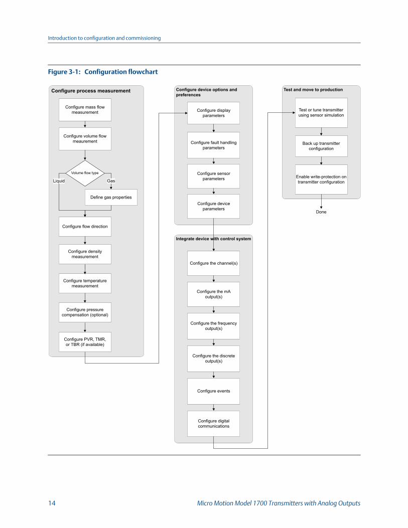
Configuration flowchartFigure 3-1:
Integrate device with control system
Configure device options and preferences
Configure process measurement
Configure mass flow measurement
Configure volume flow meaurement
Configure temperature measurement
Volume flow type
Liquid Gas
Define gas properties
Configure display parameters
Configure fault handling parameters
Configure sensor parameters
Configure device parameters
Configure the channel(s)
Configure digital communications
Test and move to production
Done
Test or tune transmitter using sensor simulation
Back up transmitter configuration
Enable write-protection on transmitter configuration
Configure the mA output(s)
Configure the frequency output(s)
Configure the discrete output(s)
Configure events
Configure density measurement
Configure flow direction
Configure PVR, TMR,or TBR (if available)
Configure pressure compensation (optional)
Introduction to configuration and commissioning
14 Micro Motion Model 1700 Transmitters with Analog Outputs
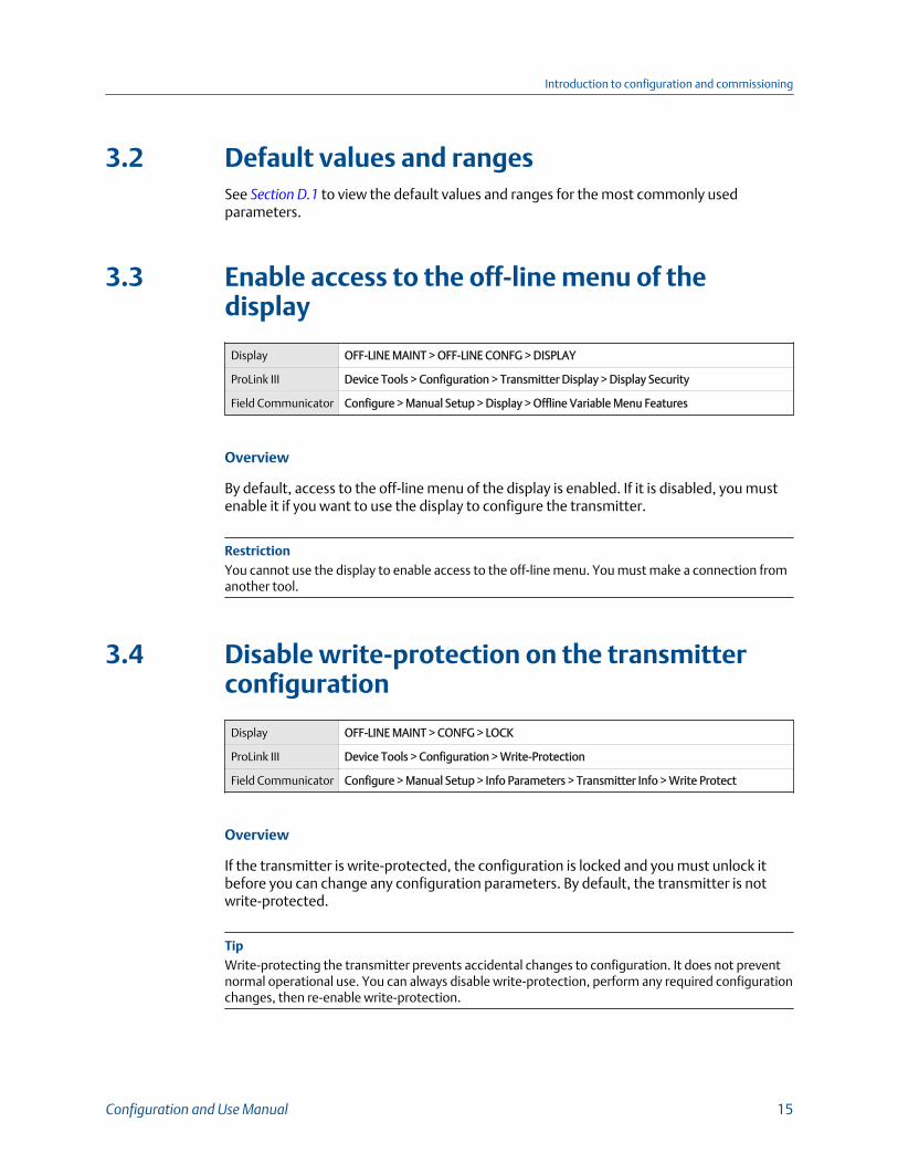
3.2 Default values and rangesSee Section D.1 to view the default values and ranges for the most commonly usedparameters.
3.3 Enable access to the off-line menu of thedisplay
Display OFF-LINE MAINT > OFF-LINE CONFG > DISPLAY
ProLink III Device Tools > Configuration > Transmitter Display > Display Security
Field Communicator Configure > Manual Setup > Display > Offline Variable Menu Features
Overview
By default, access to the off-line menu of the display is enabled. If it is disabled, you mustenable it if you want to use the display to configure the transmitter.
RestrictionYou cannot use the display to enable access to the off-line menu. You must make a connection fromanother tool.
3.4 Disable write-protection on the transmitterconfiguration
Display OFF-LINE MAINT > CONFG > LOCK
ProLink III Device Tools > Configuration > Write-Protection
Field Communicator Configure > Manual Setup > Info Parameters > Transmitter Info > Write Protect
Overview
If the transmitter is write-protected, the configuration is locked and you must unlock itbefore you can change any configuration parameters. By default, the transmitter is notwrite-protected.
TipWrite-protecting the transmitter prevents accidental changes to configuration. It does not preventnormal operational use. You can always disable write-protection, perform any required configurationchanges, then re-enable write-protection.
Introduction to configuration and commissioning
Configuration and Use Manual 15
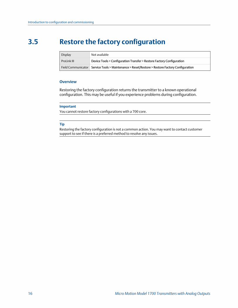
3.5 Restore the factory configuration
Display Not available
ProLink III Device Tools > Configuration Transfer > Restore Factory Configuration
Field Communicator Service Tools > Maintenance > Reset/Restore > Restore Factory Configuration
Overview
Restoring the factory configuration returns the transmitter to a known operationalconfiguration. This may be useful if you experience problems during configuration.
ImportantYou cannot restore factory configurations with a 700 core.
TipRestoring the factory configuration is not a common action. You may want to contact customersupport to see if there is a preferred method to resolve any issues.
Introduction to configuration and commissioning
16 Micro Motion Model 1700 Transmitters with Analog Outputs
4 Configure process measurementTopics covered in this chapter:
• Configure mass flow measurement
• Configure volume flow measurement for liquid applications
• Configure GSV flow measurement
• Configure Flow Direction
• Configure density measurement
• Configure temperature measurement
• Configure pressure compensation
4.1 Configure mass flow measurementThe mass flow measurement parameters control how mass flow is measured and reported.
4.1.1 Configure Mass Flow Measurement Unit
Display OFF-LINE MAINT > OFF-LINE CONFG > UNITS > MASS
ProLink III Device Tools > Configuration > Process Measurement > Flow
Field Communicator Configure > Manual Setup > Measurements > Flow > Mass Flow Unit
Overview
Mass Flow Measurement Unit specifies the unit of measure that will be used for the massflow rate. The unit used for mass total and mass inventory is derived from this unit.
Any selected measurement unit, (mass, volume or gas standard volume), is automaticallyapplied to both the mA and Frequency Outputs.
Procedure
Set Mass Flow Measurement Unit to the unit you want to use.
The default setting for Mass Flow Measurement Unit is g/sec (grams per second).
TipIf the measurement unit you want to use is not available, you can define a special measurement unit.
Configure process measurement
Configuration and Use Manual 17

Options for Mass Flow Measurement UnitThe transmitter provides a standard set of measurement units for Mass Flow MeasurementUnit, plus one user-defined special measurement unit. Different communications toolsmay use different labels for the units.
Unit description
Label
Display ProLink III Field Communica-tor
Grams per second G/S g/sec g/s
Grams per minute G/MIN g/min g/min
Grams per hour G/H g/hr g/h
Kilograms per second KG/S kg/sec kg/s
Kilograms per minute KG/MIN kg/min kg/min
Kilograms per hour KG/H kg/hr kg/h
Kilograms per day KG/D kg/day kg/d
Metric tons per minute T/MIN mTon/min MetTon/min
Metric tons per hour T/H mTon/hr MetTon/h
Metric tons per day T/D mTon/day MetTon/d
Pounds per second LB/S lbs/sec lb/s
Pounds per minute LB/MIN lbs/min lb/min
Pounds per hour LB/H lbs/hr lb/h
Pounds per day LB/D lbs/day lb/d
Short tons (2000 pounds) perminute
ST/MIN sTon/min STon/min
Short tons (2000 pounds) perhour
ST/H sTon/hr STon/h
Short tons (2000 pounds) perday
ST/D sTon/day STon/d
Long tons (2240 pounds) perhour
LT/H lTon/hr LTon/h
Long tons (2240 pounds) perday
LT/D lTon/day LTon/d
Special unit SPECL special Spcl
Configure process measurement
18 Micro Motion Model 1700 Transmitters with Analog Outputs
Define a special measurement unit for mass flow
Display Not available
ProLink III Device Tools > Configuration > Process Measurement > Flow > Special Units
Field Communicator Configure > Manual Setup > Measurements > Special Units > Mass Special Units
Overview
A special measurement unit is a user-defined unit of measure that allows you to reportprocess data, totalizer data, and inventory data in a unit that is not available in thetransmitter. A special measurement unit is calculated from an existing measurement unitusing a conversion factor.
NoteAlthough you cannot define a special measurement unit using the display, you can use the display toselect an existing special measurement unit, and to view process data using the specialmeasurement unit.
Procedure
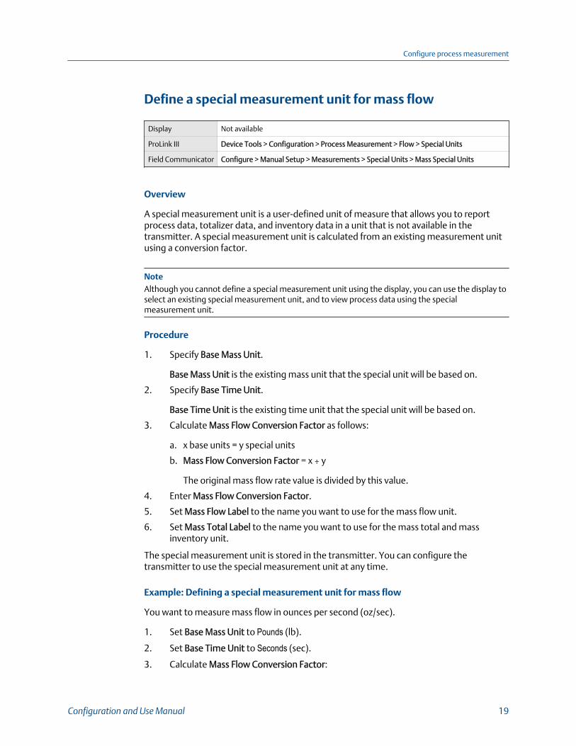
1. Specify Base Mass Unit.
Base Mass Unit is the existing mass unit that the special unit will be based on.
2. Specify Base Time Unit.
Base Time Unit is the existing time unit that the special unit will be based on.
3. Calculate Mass Flow Conversion Factor as follows:
a. x base units = y special units
b. Mass Flow Conversion Factor = x ÷ y
The original mass flow rate value is divided by this value.
4. Enter Mass Flow Conversion Factor.
5. Set Mass Flow Label to the name you want to use for the mass flow unit.
6. Set Mass Total Label to the name you want to use for the mass total and massinventory unit.
The special measurement unit is stored in the transmitter. You can configure thetransmitter to use the special measurement unit at any time.
Example: Defining a special measurement unit for mass flow
You want to measure mass flow in ounces per second (oz/sec).
1. Set Base Mass Unit to Pounds (lb).
2. Set Base Time Unit to Seconds (sec).
3. Calculate Mass Flow Conversion Factor:
Configure process measurement
Configuration and Use Manual 19
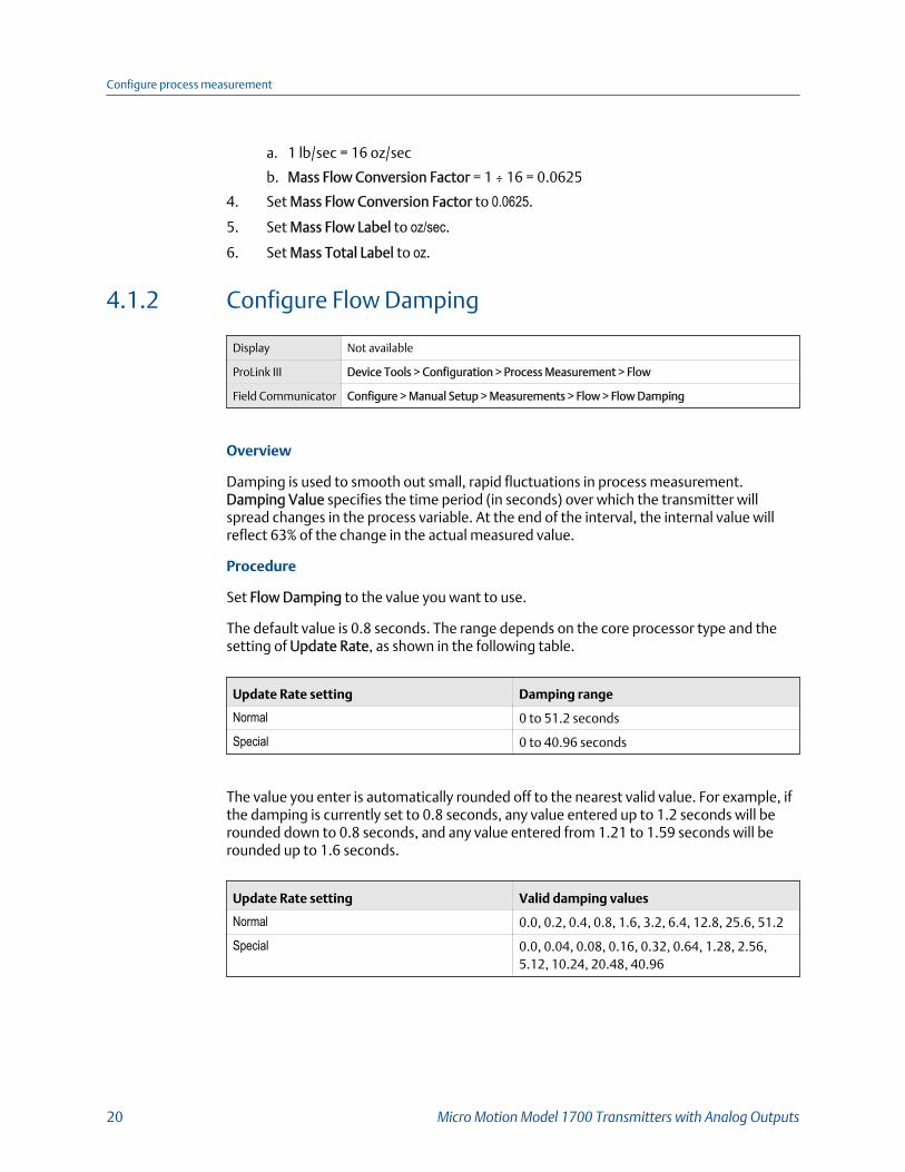
a. 1 lb/sec = 16 oz/sec
b. Mass Flow Conversion Factor = 1 ÷ 16 = 0.0625
4. Set Mass Flow Conversion Factor to 0.0625.
5. Set Mass Flow Label to oz/sec.
6. Set Mass Total Label to oz.
4.1.2 Configure Flow Damping
Display Not available
ProLink III Device Tools > Configuration > Process Measurement > Flow
Field Communicator Configure > Manual Setup > Measurements > Flow > Flow Damping
Overview
Damping is used to smooth out small, rapid fluctuations in process measurement.Damping Value specifies the time period (in seconds) over which the transmitter willspread changes in the process variable. At the end of the interval, the internal value willreflect 63% of the change in the actual measured value.
Procedure
Set Flow Damping to the value you want to use.
The default value is 0.8 seconds. The range depends on the core processor type and thesetting of Update Rate, as shown in the following table.
Update Rate setting Damping range
Normal 0 to 51.2 seconds
Special 0 to 40.96 seconds
The value you enter is automatically rounded off to the nearest valid value. For example, ifthe damping is currently set to 0.8 seconds, any value entered up to 1.2 seconds will berounded down to 0.8 seconds, and any value entered from 1.21 to 1.59 seconds will berounded up to 1.6 seconds.
Update Rate setting Valid damping values
Normal 0.0, 0.2, 0.4, 0.8, 1.6, 3.2, 6.4, 12.8, 25.6, 51.2
Special 0.0, 0.04, 0.08, 0.16, 0.32, 0.64, 1.28, 2.56,5.12, 10.24, 20.48, 40.96
Configure process measurement
20 Micro Motion Model 1700 Transmitters with Analog Outputs
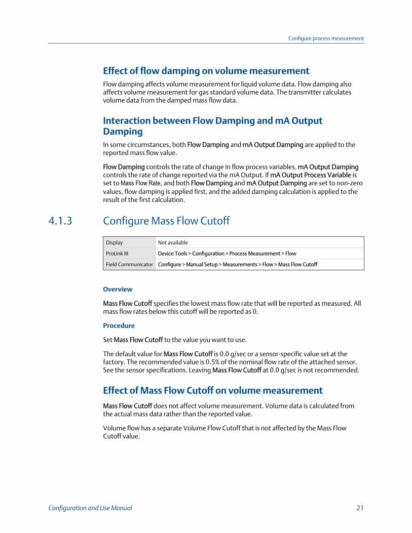
Effect of flow damping on volume measurementFlow damping affects volume measurement for liquid volume data. Flow damping alsoaffects volume measurement for gas standard volume data. The transmitter calculatesvolume data from the damped mass flow data.
Interaction between Flow Damping and mA OutputDampingIn some circumstances, both Flow Damping and mA Output Damping are applied to thereported mass flow value.
Flow Damping controls the rate of change in flow process variables. mA Output Dampingcontrols the rate of change reported via the mA Output. If mA Output Process Variable isset to Mass Flow Rate, and both Flow Damping and mA Output Damping are set to non-zerovalues, flow damping is applied first, and the added damping calculation is applied to theresult of the first calculation.
4.1.3 Configure Mass Flow Cutoff
Display Not available
ProLink III Device Tools > Configuration > Process Measurement > Flow
Field Communicator Configure > Manual Setup > Measurements > Flow > Mass Flow Cutoff
Overview
Mass Flow Cutoff specifies the lowest mass flow rate that will be reported as measured. Allmass flow rates below this cutoff will be reported as 0.
Procedure
Set Mass Flow Cutoff to the value you want to use.
The default value for Mass Flow Cutoff is 0.0 g/sec or a sensor-specific value set at thefactory. The recommended value is 0.5% of the nominal flow rate of the attached sensor.See the sensor specifications. Leaving Mass Flow Cutoff at 0.0 g/sec is not recommended.
Effect of Mass Flow Cutoff on volume measurement
Mass Flow Cutoff does not affect volume measurement. Volume data is calculated fromthe actual mass data rather than the reported value.
Volume flow has a separate Volume Flow Cutoff that is not affected by the Mass FlowCutoff value.
Configure process measurement
Configuration and Use Manual 21
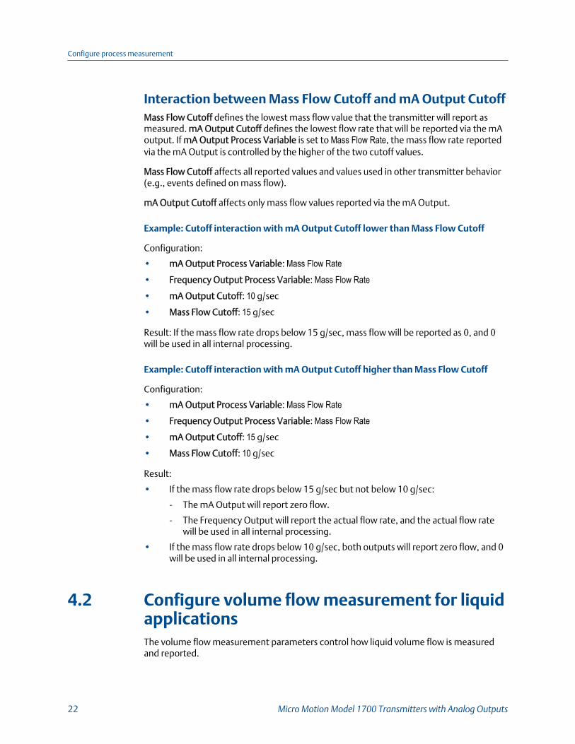
Interaction between Mass Flow Cutoff and mA Output CutoffMass Flow Cutoff defines the lowest mass flow value that the transmitter will report asmeasured. mA Output Cutoff defines the lowest flow rate that will be reported via the mAoutput. If mA Output Process Variable is set to Mass Flow Rate, the mass flow rate reportedvia the mA Output is controlled by the higher of the two cutoff values.
Mass Flow Cutoff affects all reported values and values used in other transmitter behavior(e.g., events defined on mass flow).
mA Output Cutoff affects only mass flow values reported via the mA Output.
Example: Cutoff interaction with mA Output Cutoff lower than Mass Flow Cutoff
Configuration:
• mA Output Process Variable: Mass Flow Rate• Frequency Output Process Variable: Mass Flow Rate• mA Output Cutoff: 10 g/sec
• Mass Flow Cutoff: 15 g/sec
Result: If the mass flow rate drops below 15 g/sec, mass flow will be reported as 0, and 0will be used in all internal processing.
Example: Cutoff interaction with mA Output Cutoff higher than Mass Flow Cutoff
Configuration:
• mA Output Process Variable: Mass Flow Rate• Frequency Output Process Variable: Mass Flow Rate• mA Output Cutoff: 15 g/sec
• Mass Flow Cutoff: 10 g/sec
Result:
• If the mass flow rate drops below 15 g/sec but not below 10 g/sec:
- The mA Output will report zero flow.
- The Frequency Output will report the actual flow rate, and the actual flow ratewill be used in all internal processing.
• If the mass flow rate drops below 10 g/sec, both outputs will report zero flow, and 0will be used in all internal processing.
4.2 Configure volume flow measurement for liquidapplicationsThe volume flow measurement parameters control how liquid volume flow is measuredand reported.
Configure process measurement
22 Micro Motion Model 1700 Transmitters with Analog Outputs
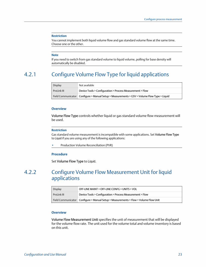
RestrictionYou cannot implement both liquid volume flow and gas standard volume flow at the same time.Choose one or the other.
NoteIf you need to switch from gas standard volume to liquid volume, polling for base density willautomatically be disabled.
4.2.1 Configure Volume Flow Type for liquid applications
Display Not available
ProLink III Device Tools > Configuration > Process Measurement > Flow
Field Communicator Configure > Manual Setup > Measurements > GSV > Volume Flow Type > Liquid
Overview
Volume Flow Type controls whether liquid or gas standard volume flow measurement willbe used.
RestrictionGas standard volume measurement is incompatible with some applications. Set Volume Flow Typeto Liquid if you are using any of the following applications:
• Production Volume Reconciliation (PVR)
Procedure
Set Volume Flow Type to Liquid.
4.2.2 Configure Volume Flow Measurement Unit for liquidapplications
Display OFF-LINE MAINT > OFF-LINE CONFG > UNITS > VOL
ProLink III Device Tools > Configuration > Process Measurement > Flow
Field Communicator Configure > Manual Setup > Measurements > Flow > Volume Flow Unit
Overview
Volume Flow Measurement Unit specifies the unit of measurement that will be displayedfor the volume flow rate. The unit used for the volume total and volume inventory is basedon this unit.
Configure process measurement
Configuration and Use Manual 23
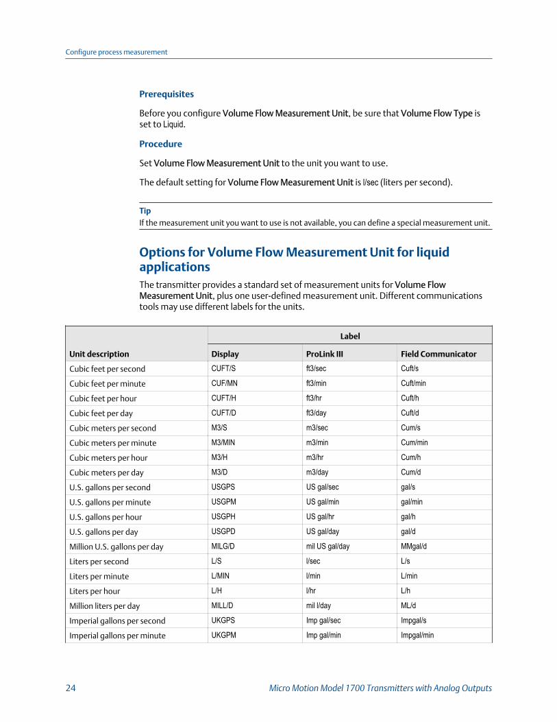
Prerequisites
Before you configure Volume Flow Measurement Unit, be sure that Volume Flow Type isset to Liquid.
Procedure
Set Volume Flow Measurement Unit to the unit you want to use.
The default setting for Volume Flow Measurement Unit is l/sec (liters per second).
TipIf the measurement unit you want to use is not available, you can define a special measurement unit.
Options for Volume Flow Measurement Unit for liquidapplicationsThe transmitter provides a standard set of measurement units for Volume FlowMeasurement Unit, plus one user-defined measurement unit. Different communicationstools may use different labels for the units.
Unit description
Label
Display ProLink III Field Communicator
Cubic feet per second CUFT/S ft3/sec Cuft/s
Cubic feet per minute CUF/MN ft3/min Cuft/min
Cubic feet per hour CUFT/H ft3/hr Cuft/h
Cubic feet per day CUFT/D ft3/day Cuft/d
Cubic meters per second M3/S m3/sec Cum/s
Cubic meters per minute M3/MIN m3/min Cum/min
Cubic meters per hour M3/H m3/hr Cum/h
Cubic meters per day M3/D m3/day Cum/d
U.S. gallons per second USGPS US gal/sec gal/s
U.S. gallons per minute USGPM US gal/min gal/min
U.S. gallons per hour USGPH US gal/hr gal/h
U.S. gallons per day USGPD US gal/day gal/d
Million U.S. gallons per day MILG/D mil US gal/day MMgal/d
Liters per second L/S l/sec L/s
Liters per minute L/MIN l/min L/min
Liters per hour L/H l/hr L/h
Million liters per day MILL/D mil l/day ML/d
Imperial gallons per second UKGPS Imp gal/sec Impgal/s
Imperial gallons per minute UKGPM Imp gal/min Impgal/min
Configure process measurement
24 Micro Motion Model 1700 Transmitters with Analog Outputs
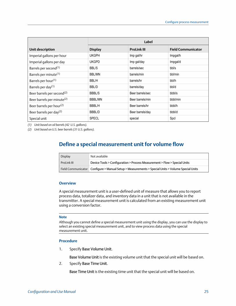
Unit description
Label
Display ProLink III Field Communicator
Imperial gallons per hour UKGPH Imp gal/hr Impgal/h
Imperial gallons per day UKGPD Imp gal/day Impgal/d
Barrels per second(1) BBL/S barrels/sec bbl/s
Barrels per minute(1) BBL/MN barrels/min bbl/min
Barrels per hour(1) BBL/H barrels/hr bbl/h
Barrels per day(1) BBL/D barrels/day bbl/d
Beer barrels per second(2) BBBL/S Beer barrels/sec bbbl/s
Beer barrels per minute(2) BBBL/MN Beer barrels/min bbbl/min
Beer barrels per hour(2) BBBL/H Beer barrels/hr bbbl/h
Beer barrels per day(2) BBBL/D Beer barrels/day bbbl/d
Special unit SPECL special Spcl
(1) Unit based on oil barrels (42 U.S. gallons).
(2) Unit based on U.S. beer barrels (31 U.S. gallons).
Define a special measurement unit for volume flow
Display Not available
ProLink III Device Tools > Configuration > Process Measurement > Flow > Special Units
Field Communicator Configure > Manual Setup > Measurements > Special Units > Volume Special Units
Overview
A special measurement unit is a user-defined unit of measure that allows you to reportprocess data, totalizer data, and inventory data in a unit that is not available in thetransmitter. A special measurement unit is calculated from an existing measurement unitusing a conversion factor.
NoteAlthough you cannot define a special measurement unit using the display, you can use the display toselect an existing special measurement unit, and to view process data using the specialmeasurement unit.
Procedure
1. Specify Base Volume Unit.
Base Volume Unit is the existing volume unit that the special unit will be based on.
2. Specify Base Time Unit.
Base Time Unit is the existing time unit that the special unit will be based on.
Configure process measurement
Configuration and Use Manual 25

3. Calculate Volume Flow Conversion Factor as follows:
a. x base units = y special units
b. Volume Flow Conversion Factor = x ÷ y
4. Enter Volume Flow Conversion Factor.
The original volume flow rate value is divided by this conversion factor.
5. Set Volume Flow Label to the name you want to use for the volume flow unit.
6. Set Volume Total Label to the name you want to use for the volume total andvolume inventory unit.
The special measurement unit is stored in the transmitter. You can configure thetransmitter to use the special measurement unit at any time.
Example: Defining a special measurement unit for volume flow
You want to measure volume flow in pints per second (pints/sec).
1. Set Base Volume Unit to Gallons (gal).
2. Set Base Time Unit to Seconds (sec).
3. Calculate the conversion factor:
a. 1 gal/sec = 8 pints/sec
b. Volume Flow Conversion Factor = 1 ÷ 8 = 0.1250
4. Set Volume Flow Conversion Factor to 0.1250.
5. Set Volume Flow Label to pints/sec.
6. Set Volume Total Label to pints.
4.2.3 Configure Volume Flow Cutoff
Display Not available
ProLink III Device Tools > Configuration > Process Measurement > Flow
Field Communicator Configure > Manual Setup > Measurements > Flow > Volume Flow Cutoff
Overview
Volume Flow Cutoff specifies the lowest volume flow rate that will be reported asmeasured. All volume flow rates below this cutoff are reported as 0.
Procedure
Set Volume Flow Cutoff to the value you want to use.
The default value for Volume Flow Cutoff is 0.0 l/sec (liters per second). The lower limit is0.
Configure process measurement
26 Micro Motion Model 1700 Transmitters with Analog Outputs
Interaction between Volume Flow Cutoff and mAO CutoffVolume Flow Cutoff defines the lowest liquid volume flow value that the transmitter willreport as measured. mAO Cutoff defines the lowest flow rate that will be reported via themA Output. If mA Output Process Variable is set to Volume Flow Rate, the volume flow ratereported via the mA Output is controlled by the higher of the two cutoff values.
Volume Flow Cutoff affects both the volume flow values reported via the outputs and thevolume flow values used in other transmitter behavior (e.g., events defined on the volumeflow).
mAO Cutoff affects only flow values reported via the mA Output.
Example: Cutoff interaction with mAO Cutoff lower than Volume Flow Cutoff
Configuration:
• mA Output Process Variable: Volume Flow Rate• Frequency Output Process Variable: Volume Flow Rate• AO Cutoff: 10 l/sec
• Volume Flow Cutoff: 15 l/sec
Result: If the volume flow rate drops below 15 l/sec, volume flow will be reported as 0, and0 will be used in all internal processing.
Example: Cutoff interaction with mAO Cutoff higher than Volume Flow Cutoff
Configuration:
• mA Output Process Variable: Volume Flow Rate• Frequency Output Process Variable: Volume Flow Rate• AO Cutoff: 15 l/sec
• Volume Flow Cutoff: 10 l/sec
Result:
• If the volume flow rate drops below 15 l/sec but not below 10 l/sec:
- The mA Output will report zero flow.
- The Frequency Output will report the actual flow rate, and the actual flow ratewill be used in all internal processing.
• If the volume flow rate drops below 10 l/sec, both outputs will report zero flow, and0 will be used in all internal processing.
4.3 Configure GSV flow measurementThe gas standard volume (GSV) flow measurement parameters control how volume flow ismeasured and reported in a gas application.
Configure process measurement
Configuration and Use Manual 27

RestrictionYou cannot implement both liquid volume flow and gas standard volume flow at the same time.Choose one or the other.
4.3.1 Configure Volume Flow Type for gas applications
Display Not available
ProLink III Device Tools > Configuration > Process Measurement > Flow
Field Communicator Configure > Manual Setup > Measurements > GSV > Volume Flow Type > Standard Gas
Volume
Overview
Volume Flow Type controls whether liquid or gas standard volume flow measurement isused.
RestrictionGas standard volume measurement is incompatible with some applications. Set Volume Flow Typeto Liquid if you are using any of the following applications:
• Production Volume Reconciliation (PVR)
Procedure
Set Volume Flow Type to Gas Standard Volume.
4.3.2 Configure Standard Density of Gas
Display Not available
ProLink III Device Tools > Configuration > Process Measurement > Flow
Field Communicator Configure > Manual Setup > Measurements > GSV > Gas Ref Density
Overview
The Standard Density of Gas value is the gas density at standard reference conditions. Useit to convert the measured mass flow data to volume flow at reference conditions.
Prerequisites
Ensure that Density Measurement Unit is set to the measurement unit you want to use forStandard Density of Gas.
Procedure
From the Source field, choose the method to supply gas base density data and perform therequired setup.
Configure process measurement
28 Micro Motion Model 1700 Transmitters with Analog Outputs

Option Description
Fixed Value or DigitalCommunications
A host writes gas base density data to the meter at appropriate intervals.
Continue to Configure fixed value or digital communications.
Poll for external value The meter polls an external HART device for gas base density data in orderto then compute gas standard volume from the mass flow and gas basedensity.
Continue to Poll for external value.
Configure fixed value or digital communications
Prerequisites
Section 4.3.2
Procedure
1. Set Standard Density of Gas to the standard reference density of the gas you aremeasuring.
NoteProLink III provides a guided method that you can use to calculate your gas base density, ifyou do not know it.
2. Continue to Section 4.3.3.
Poll for external value
Prerequisites
Section 4.3.2
Procedure
1. Set Polling Slot to an available slot.
2. Set Polling Control n as one of the following options:
The n is the value you selected in the Polling Slot field.
If there is another master, and if that master is primary, then set this field tosecondary. If the other master is secondary, then set this field to primary.
Option Description
Poll as Primary No other HART masters will be on the network.
Poll as Secondary Other HART masters will be on the network.
3. Set External Device Tag n to the HART tag of the device being polled.
The n is the value you selected in the Polling Slot field.
Configure process measurement
Configuration and Use Manual 29

• The device being polled (slave) cannot have special units set for density.Otherwise, the master will reject the base density and report the following alarm:
A115: No External Input or Polled Data Alert• On the slave side, setup the HART Primary Variable for Base Density. The master
will reject anything other than Base Density for the HART Primary Variable andtrigger an A115 alarm.
• The density units on the transmitter and the polled device can be different aslong as they can be classified as density units; for example, kg/m3 and g/cm3.The transmitter converts the polled units into compatible specified units.
For wiring and setup instructions for a polled device, refer to the Micro Motion GasDensity Meters (GDM) Installation manual or the Micro Motion Specific Gravity Meters(SGM) Installation manual.
4. Continue to Section 4.3.3.
4.3.3 Configure Gas Standard Volume Flow Unit
Display OFF-LINE MAINT > OFF-LINE CONFG > UNITS > GSV
ProLink III Device Tools > Configuration > Process Measurement > Flow
Field Communicator Configure > Manual Setup > Measurements > GSV > GSV Flow Unit
Overview
Gas Standard Volume Flow Unit specifies the unit of measure that will be displayed for thegas standard volume flow. The measurement unit used for the gas volume total and thegas volume inventory is derived from this unit.
Prerequisites
Before you configure Gas Standard Volume Flow Unit, be sure that Volume Flow Type is setto Gas Standard Volume.
For polling, the first transmitter (master) requests density from a second transmitter(slave) via HART communications. Special units for GSV are allowed on the master side,but the device being polled (slave) cannot have special units set for density, otherwise themaster will reject the base density and report an A115: No External Input or Polled DataAlert.
Procedure
Set Gas Standard Volume Flow Unit to the unit you want to use.
The default setting for Gas Standard Volume Flow Unit is SCFM (Standard Cubic Feet perMinute).
TipIf the measurement unit you want to use is not available, you can define a special measurement unit.
Configure process measurement
30 Micro Motion Model 1700 Transmitters with Analog Outputs

Options for Gas Standard Volume Flow UnitThe transmitter provides a standard set of measurement units for Gas Standard VolumeFlow Unit, plus one user-defined special measurement unit. Different communicationstools may use different labels for the units.
Unit description
Label
Display ProLink III Field Communicator
Normal cubic meters per second NM3/S Nm3/sec Nm3/sec
Normal cubic meters per minute NM3/MN Nm3/sec Nm3/min
Normal cubic meters per hour NM3/H Nm3/hr Nm3/hr
Normal cubic meters per day NM3/D Nm3/day Nm3/day
Normal liters per second NLPS NLPS NLPS
Normal liters per minute NLPM NLPM NLPM
Normal liters per hour NLPH NLPH NLPH
Normal liters per day NLPD NLPD NLPD
Standard cubic feet per second SCFS SCFS SCFS
Standard cubic feet per minute SCFM SCFM SCFM
Standard cubic feet per hour SCFH SCFH SCFH
Standard cubic feet per day SCFD SCFD SCFD
Standard cubic meters per second SM3/S Sm3/sec Sm3/sec
Standard cubic meters per minute SM3/MN Sm3/min Sm3/min
Standard cubic meters per hour SM3/H Sm3/hr Sm3/hr
Standard cubic meters per day SM3/D Sm3/day Sm3/day
Standard liters per second SLPS SLPS SLPS
Standard liters per minute SLPM SLPM SLPM
Standard liters per hour SLPH SLPH SLPH
Standard liters per day SLPD SLPD SLPD
Special measurement unit SPECL special Special
Define a special measurement unit for gas standard volumeflow
Display Not available
ProLink III Device Tools > Configuration > Process Measurement > Flow > Special Units
Field Communicator Configure > Manual Setup > Measurements > Special Units > Special GSV Units
Configure process measurement
Configuration and Use Manual 31

Overview
A special measurement unit is a user-defined unit of measure that allows you to reportprocess data, totalizer data, and inventory data in a unit that is not available in thetransmitter. A special measurement unit is calculated from an existing measurement unitusing a conversion factor.
NoteAlthough you cannot define a special measurement unit using the display, you can use the display toselect an existing special measurement unit, and to view process data using the specialmeasurement unit.
Procedure
1. Specify Base Gas Standard Volume Unit.
Base Gas Standard Volume Unit is the existing gas standard volume unit that thespecial unit will be based on.
2. Specify Base Time Unit.
Base Time Unit is the existing time unit that the special unit will be based on.
3. Calculate Gas Standard Volume Flow Conversion Factor as follows:
a. x base units = y special units
b. Gas Standard Volume Flow Conversion Factor = x ÷ y
4. Enter the Gas Standard Volume Flow Conversion Factor.
The original gas standard volume flow value is divided by this conversion factor.
5. Set Gas Standard Volume Flow Label to the name you want to use for the gasstandard volume flow unit.
6. Set Gas Standard Volume Total Label to the name you want to use for the gasstandard volume total and gas standard volume inventory unit.
The special measurement unit is stored in the transmitter. You can configure thetransmitter to use the special measurement unit at any time.
Example: Defining a special measurement unit for gas standard volume flow
You want to measure gas standard volume flow in thousands of standard cubic feet perminute.
1. Set Base Gas Standard Volume Unit to SCF.
2. Set Base Time Unit to minutes (min).
3. Calculate the conversion factor:
a. 1 thousands of standard cubic feet per minute = 1000 cubic feet per minute
b. Gas Standard Volume Flow Conversion Factor = 1 ÷ 1000 = 0.001 standard
4. Set Gas Standard Volume Flow Conversion Factor to 0.001.
5. Set Gas Standard Volume Flow Label to MSCFM.
Configure process measurement
32 Micro Motion Model 1700 Transmitters with Analog Outputs
6. Set Gas Standard Volume Total Label to MSCF.
4.3.4 Configure Gas Standard Volume Flow Cutoff
Display Not available
ProLink III Device Tools > Configuration > Process Measurement > Flow
Field Communicator Configure > Manual Setup > Measurements > GSV > GSV Cutoff
Overview
Gas Standard Volume Flow Cutoff specifies the lowest gas standard volume flow rate thatwill reported as measured. All gas standard volume flow rates below this cutoff will bereported as 0.
Procedure
Set Gas Standard Volume Flow Cutoff to the value you want to use.
The default value for Gas Standard Volume Flow Cutoff is 0.0. The lower limit is 0.0. Thereis no upper limit.
Interaction between Gas Standard Volume Flow Cutoff andmA Output CutoffGas Standard Volume Flow Cutoff defines the lowest Gas Standard Volume flow value thatthe transmitter will report as measured. mA Output Cutoff defines the lowest flow ratethat will be reported via the mA Output. If mA Output Process Variable is set to GasStandard Volume Flow Rate, the volume flow rate reported via the mA Output is controlled bythe higher of the two cutoff values.
Gas Standard Volume Flow Cutoff affects both the gas standard volume flow valuesreported via outputs and the gas standard volume flow values used in other transmitterbehavior (e.g., events defined on gas standard volume flow).
mA Output Cutoff affects only flow values reported via the mA Output.
Example: Cutoff interaction with mA Output Cutoff lower than Gas Standard VolumeFlow Cutoff
Configuration:
• mA Output Process Variable for the primary mA Output: Gas Standard Volume FlowRate
• Frequency Output Process Variable: Gas Standard Volume Flow Rate• mA Output Cutoff for the primary mA Output: 10 SLPM (standard liters per minute)
• Gas Standard Volume Flow Cutoff: 15 SLPM
Result: If the gas standard volume flow rate drops below 15 SLPM, the volume flow will bereported as 0, and 0 will be used in all internal processing.
Configure process measurement
Configuration and Use Manual 33
Example: Cutoff interaction with mA Output Cutoff higher than Gas Standard VolumeFlow Cutoff
Configuration:
• mA Output Process Variable for the primary mA Output: Gas Standard Volume FlowRate
• Frequency Output Process Variable: Gas Standard Volume Flow Rate• mA Output Cutoff for the primary mA Output: 15 SLPM (standard liters per minute)
• Gas Standard Volume Flow Cutoff: 10 SLPM
Result:
• If the gas standard volume flow rate drops below 15 SLPM but not below 10 SLPM:
- The primary mA Output will report zero flow.
- The Frequency Output will report the actual flow rate, and the actual flow ratewill be used in all internal processing.
• If the gas standard volume flow rate drops below 10 SLPM, both outputs will reportzero flow, and 0 will be used in all internal processing.
4.4 Configure Flow Direction
Display Not available
ProLink III Device Tools > Configuration > Process Measurement > Flow
Field Communicator Configure > Manual Setup > Measurements > Flow > Flow Direction
Overview
Flow Direction controls how forward flow and reverse flow affect flow measurement andreporting.
Flow Direction is defined with respect to the flow arrow on the sensor:
• Forward flow (positive flow) moves in the direction of the flow arrow on the sensor.
• Reverse flow (negative flow) moves in the direction opposite to the flow arrow onthe sensor.
TipMicro Motion sensors are bidirectional. Measurement accuracy is not affected by actual flowdirection or the setting of the Flow Direction parameter.
Procedure
Set Flow Direction to the value you want to use.
The default setting is Forward.
Configure process measurement
34 Micro Motion Model 1700 Transmitters with Analog Outputs

4.4.1 Options for Flow Direction
Flow Direction settingRelationship to Flow Direction arrowon sensorProLink III Field Communicator
Forward Forward Appropriate when the Flow Direction ar-row is in the same direction as the major-ity of flow.
Reverse Reverse Appropriate when the Flow Direction ar-row is in the opposite direction from themajority of flow.
Absolute Value Absolute Value Flow Direction arrow is not relevant.
Bidirectional Bi directional Appropriate when both forward and re-verse flow are expected, and forwardflow will dominate, but the amount of re-verse flow will be significant.
Negate Forward Negate/Forward Only Appropriate when the Flow Direction ar-row is in the opposite direction from themajority of flow.
Negate Bidirectional Negate/Bi-directional Appropriate when both forward and re-verse flow are expected, and reverse flowwill dominate, but the amount of for-ward flow will be significant.
Effect of Flow Direction on mA OutputsFlow Direction affects how the transmitter reports flow values via the mA Outputs. The mAOutputs are affected by Flow Direction only if mA Output Process Variable is set to a flowvariable.
Flow Direction and mA Outputs
The effect of Flow Direction on the mA Outputs depends on Lower Range Value configuredfor the mA Output:
• If Lower Range Value is set to 0, see Figure 4‐1.
• If Lower Range Value is set to a negative value, see Figure 4‐2.
Configure process measurement
Configuration and Use Manual 35
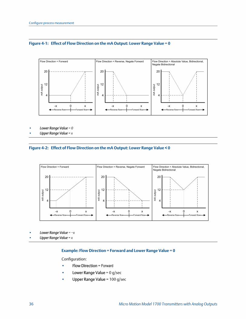
Effect of Flow Direction on the mA Output: Lower Range Value = 0Figure 4-1:
Flow Direction = Forward
mA
out
put
-x 0 xReverse flow Forward flow
20
12
4
Flow Direction = Reverse, Negate Forward
mA
out
put
-x 0 xReverse flow Forward flow
20
12
4
Flow Direction = Absolute Value, Bidirectional, Negate Bidirectional
mA
out
put
-x 0 xReverse flow Forward flow
20
12
4
• Lower Range Value = 0• Upper Range Value = x
Effect of Flow Direction on the mA Output: Lower Range Value < 0Figure 4-2:
Flow Direction = Forward
mA
out
put
-x 0 xReverse flow Forward flow
20
12
4
Flow Direction = Reverse, Negate Forward
mA
out
put
-x 0 xReverse flow Forward flow
20
12
4
Flow Direction = Absolute Value, Bidirectional, Negate Bidirectional
mA
out
put
-x 0 xReverse flow Forward flow
20
12
4
• Lower Range Value = −x• Upper Range Value = x
Example: Flow Direction = Forward and Lower Range Value = 0
Configuration:
• Flow Direction = Forward• Lower Range Value = 0 g/sec
• Upper Range Value = 100 g/sec
Configure process measurement
36 Micro Motion Model 1700 Transmitters with Analog Outputs
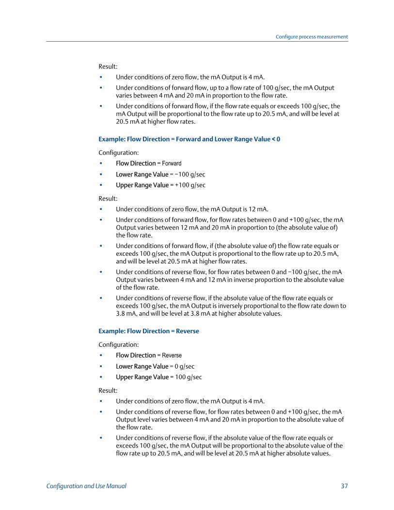
Result:
• Under conditions of zero flow, the mA Output is 4 mA.
• Under conditions of forward flow, up to a flow rate of 100 g/sec, the mA Outputvaries between 4 mA and 20 mA in proportion to the flow rate.
• Under conditions of forward flow, if the flow rate equals or exceeds 100 g/sec, themA Output will be proportional to the flow rate up to 20.5 mA, and will be level at20.5 mA at higher flow rates.
Example: Flow Direction = Forward and Lower Range Value < 0
Configuration:
• Flow Direction = Forward• Lower Range Value = −100 g/sec
• Upper Range Value = +100 g/sec
Result:
• Under conditions of zero flow, the mA Output is 12 mA.
• Under conditions of forward flow, for flow rates between 0 and +100 g/sec, the mAOutput varies between 12 mA and 20 mA in proportion to (the absolute value of)the flow rate.
• Under conditions of forward flow, if (the absolute value of) the flow rate equals orexceeds 100 g/sec, the mA Output is proportional to the flow rate up to 20.5 mA,and will be level at 20.5 mA at higher flow rates.
• Under conditions of reverse flow, for flow rates between 0 and −100 g/sec, the mAOutput varies between 4 mA and 12 mA in inverse proportion to the absolute valueof the flow rate.
• Under conditions of reverse flow, if the absolute value of the flow rate equals orexceeds 100 g/sec, the mA Output is inversely proportional to the flow rate down to3.8 mA, and will be level at 3.8 mA at higher absolute values.
Example: Flow Direction = Reverse
Configuration:
• Flow Direction = Reverse• Lower Range Value = 0 g/sec
• Upper Range Value = 100 g/sec
Result:
• Under conditions of zero flow, the mA Output is 4 mA.
• Under conditions of reverse flow, for flow rates between 0 and +100 g/sec, the mAOutput level varies between 4 mA and 20 mA in proportion to the absolute value ofthe flow rate.
• Under conditions of reverse flow, if the absolute value of the flow rate equals orexceeds 100 g/sec, the mA Output will be proportional to the absolute value of theflow rate up to 20.5 mA, and will be level at 20.5 mA at higher absolute values.
Configure process measurement
Configuration and Use Manual 37
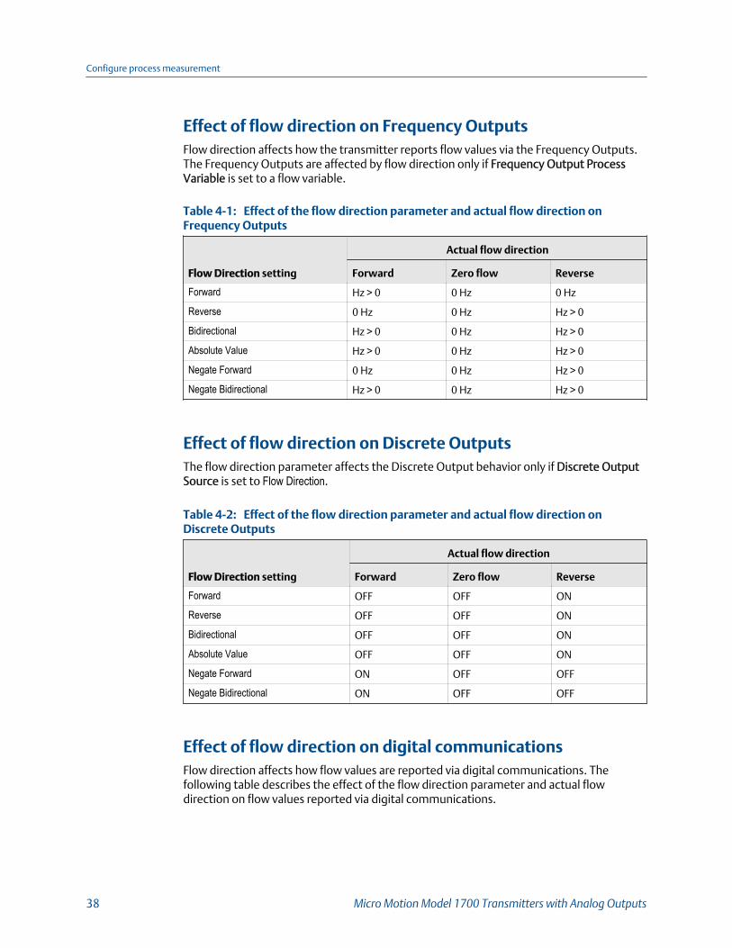
Effect of flow direction on Frequency OutputsFlow direction affects how the transmitter reports flow values via the Frequency Outputs.The Frequency Outputs are affected by flow direction only if Frequency Output ProcessVariable is set to a flow variable.
Effect of the flow direction parameter and actual flow direction onFrequency OutputsTable 4-1:
Flow Direction setting
Actual flow direction
Forward Zero flow Reverse
Forward Hz > 0 0 Hz 0 Hz
Reverse 0 Hz 0 Hz Hz > 0
Bidirectional Hz > 0 0 Hz Hz > 0
Absolute Value Hz > 0 0 Hz Hz > 0
Negate Forward 0 Hz 0 Hz Hz > 0
Negate Bidirectional Hz > 0 0 Hz Hz > 0
Effect of flow direction on Discrete OutputsThe flow direction parameter affects the Discrete Output behavior only if Discrete OutputSource is set to Flow Direction.
Effect of the flow direction parameter and actual flow direction onDiscrete OutputsTable 4-2:
Flow Direction setting
Actual flow direction
Forward Zero flow Reverse
Forward OFF OFF ON
Reverse OFF OFF ON
Bidirectional OFF OFF ON
Absolute Value OFF OFF ON
Negate Forward ON OFF OFF
Negate Bidirectional ON OFF OFF
Effect of flow direction on digital communicationsFlow direction affects how flow values are reported via digital communications. Thefollowing table describes the effect of the flow direction parameter and actual flowdirection on flow values reported via digital communications.
Configure process measurement
38 Micro Motion Model 1700 Transmitters with Analog Outputs
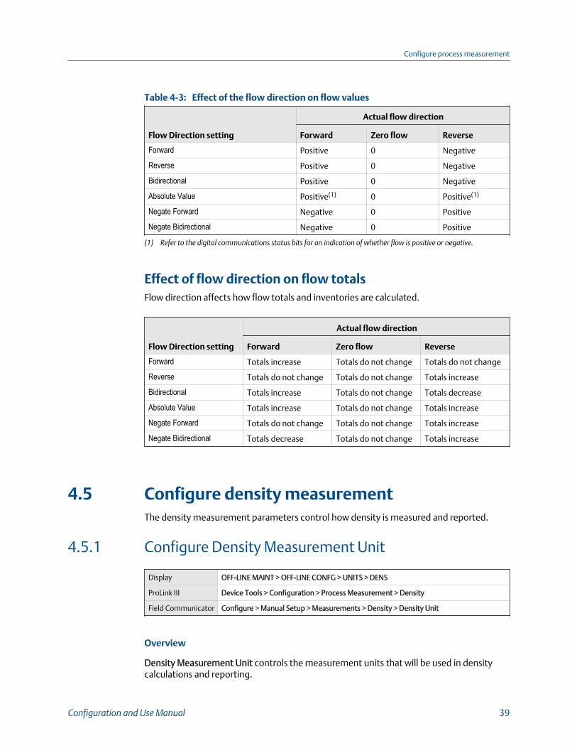
Effect of the flow direction on flow valuesTable 4-3:
Flow Direction setting
Actual flow direction
Forward Zero flow Reverse
Forward Positive 0 Negative
Reverse Positive 0 Negative
Bidirectional Positive 0 Negative
Absolute Value Positive(1) 0 Positive(1)
Negate Forward Negative 0 Positive
Negate Bidirectional Negative 0 Positive
(1) Refer to the digital communications status bits for an indication of whether flow is positive or negative.
Effect of flow direction on flow totalsFlow direction affects how flow totals and inventories are calculated.
Flow Direction setting
Actual flow direction
Forward Zero flow Reverse
Forward Totals increase Totals do not change Totals do not change
Reverse Totals do not change Totals do not change Totals increase
Bidirectional Totals increase Totals do not change Totals decrease
Absolute Value Totals increase Totals do not change Totals increase
Negate Forward Totals do not change Totals do not change Totals increase
Negate Bidirectional Totals decrease Totals do not change Totals increase
4.5 Configure density measurementThe density measurement parameters control how density is measured and reported.
4.5.1 Configure Density Measurement Unit
Display OFF-LINE MAINT > OFF-LINE CONFG > UNITS > DENS
ProLink III Device Tools > Configuration > Process Measurement > Density
Field Communicator Configure > Manual Setup > Measurements > Density > Density Unit
Overview
Density Measurement Unit controls the measurement units that will be used in densitycalculations and reporting.
Configure process measurement
Configuration and Use Manual 39
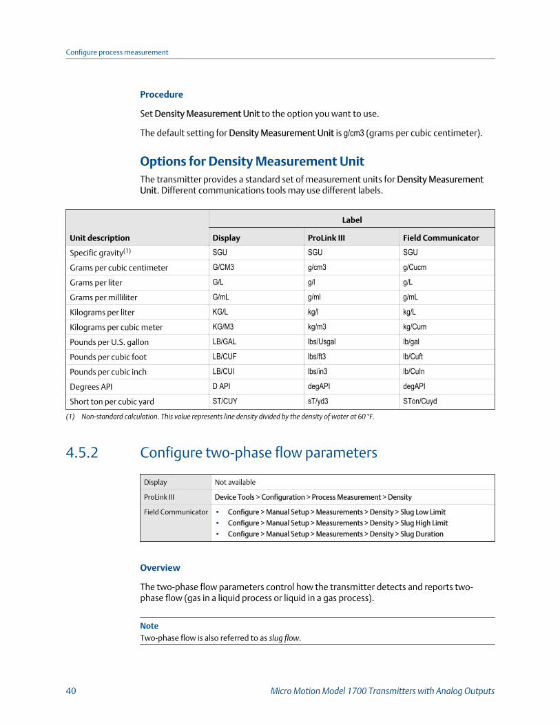
Procedure
Set Density Measurement Unit to the option you want to use.
The default setting for Density Measurement Unit is g/cm3 (grams per cubic centimeter).
Options for Density Measurement UnitThe transmitter provides a standard set of measurement units for Density MeasurementUnit. Different communications tools may use different labels.
Unit description
Label
Display ProLink III Field Communicator
Specific gravity(1) SGU SGU SGU
Grams per cubic centimeter G/CM3 g/cm3 g/Cucm
Grams per liter G/L g/l g/L
Grams per milliliter G/mL g/ml g/mL
Kilograms per liter KG/L kg/l kg/L
Kilograms per cubic meter KG/M3 kg/m3 kg/Cum
Pounds per U.S. gallon LB/GAL lbs/Usgal lb/gal
Pounds per cubic foot LB/CUF lbs/ft3 lb/Cuft
Pounds per cubic inch LB/CUI lbs/in3 lb/CuIn
Degrees API D API degAPI degAPI
Short ton per cubic yard ST/CUY sT/yd3 STon/Cuyd
(1) Non‐standard calculation. This value represents line density divided by the density of water at 60 °F.
4.5.2 Configure two-phase flow parameters
Display Not available
ProLink III Device Tools > Configuration > Process Measurement > Density
Field Communicator • Configure > Manual Setup > Measurements > Density > Slug Low Limit
• Configure > Manual Setup > Measurements > Density > Slug High Limit
• Configure > Manual Setup > Measurements > Density > Slug Duration
Overview
The two-phase flow parameters control how the transmitter detects and reports two-phase flow (gas in a liquid process or liquid in a gas process).
NoteTwo-phase flow is also referred to as slug flow.
Configure process measurement
40 Micro Motion Model 1700 Transmitters with Analog Outputs
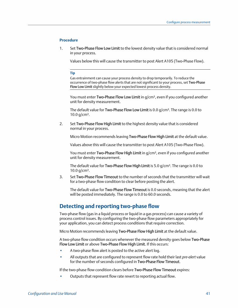
Procedure
1. Set Two-Phase Flow Low Limit to the lowest density value that is considered normalin your process.
Values below this will cause the transmitter to post Alert A105 (Two-Phase Flow).
TipGas entrainment can cause your process density to drop temporarily. To reduce theoccurrence of two-phase flow alerts that are not significant to your process, set Two-PhaseFlow Low Limit slightly below your expected lowest process density.
You must enter Two-Phase Flow Low Limit in g/cm³, even if you configured anotherunit for density measurement.
The default value for Two-Phase Flow Low Limit is 0.0 g/cm³. The range is 0.0 to10.0 g/cm³.
2. Set Two-Phase Flow High Limit to the highest density value that is considerednormal in your process.
Micro Motion recommends leaving Two-Phase Flow High Limit at the default value.
Values above this will cause the transmitter to post Alert A105 (Two-Phase Flow).
You must enter Two-Phase Flow High Limit in g/cm³, even if you configured anotherunit for density measurement.
The default value for Two-Phase Flow High Limit is 5.0 g/cm³. The range is 0.0 to10.0 g/cm³.
3. Set Two-Phase Flow Timeout to the number of seconds that the transmitter will waitfor a two-phase flow condition to clear before posting the alert.
The default value for Two-Phase Flow Timeout is 0.0 seconds, meaning that the alertwill be posted immediately. The range is 0.0 to 60.0 seconds.
Detecting and reporting two-phase flowTwo-phase flow (gas in a liquid process or liquid in a gas process) can cause a variety ofprocess control issues. By configuring the two-phase flow parameters appropriately foryour application, you can detect process conditions that require correction.
Micro Motion recommends leaving Two-Phase Flow High Limit at the default value.
A two-phase flow condition occurs whenever the measured density goes below Two-PhaseFlow Low Limit or above Two-Phase Flow High Limit. If this occurs:
• A two-phase flow alert is posted to the active alert log.
• All outputs that are configured to represent flow rate hold their last pre‐alert valuefor the number of seconds configured in Two-Phase Flow Timeout.
If the two-phase flow condition clears before Two-Phase Flow Timeout expires:
• Outputs that represent flow rate revert to reporting actual flow.
Configure process measurement
Configuration and Use Manual 41
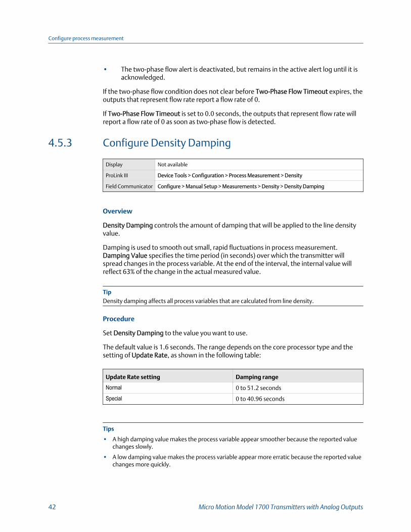
• The two-phase flow alert is deactivated, but remains in the active alert log until it isacknowledged.
If the two-phase flow condition does not clear before Two-Phase Flow Timeout expires, theoutputs that represent flow rate report a flow rate of 0.
If Two-Phase Flow Timeout is set to 0.0 seconds, the outputs that represent flow rate willreport a flow rate of 0 as soon as two-phase flow is detected.
4.5.3 Configure Density Damping
Display Not available
ProLink III Device Tools > Configuration > Process Measurement > Density
Field Communicator Configure > Manual Setup > Measurements > Density > Density Damping
Overview
Density Damping controls the amount of damping that will be applied to the line densityvalue.
Damping is used to smooth out small, rapid fluctuations in process measurement.Damping Value specifies the time period (in seconds) over which the transmitter willspread changes in the process variable. At the end of the interval, the internal value willreflect 63% of the change in the actual measured value.
TipDensity damping affects all process variables that are calculated from line density.
Procedure
Set Density Damping to the value you want to use.
The default value is 1.6 seconds. The range depends on the core processor type and thesetting of Update Rate, as shown in the following table:
Update Rate setting Damping range
Normal 0 to 51.2 seconds
Special 0 to 40.96 seconds
Tips
• A high damping value makes the process variable appear smoother because the reported valuechanges slowly.
• A low damping value makes the process variable appear more erratic because the reported valuechanges more quickly.
Configure process measurement
42 Micro Motion Model 1700 Transmitters with Analog Outputs
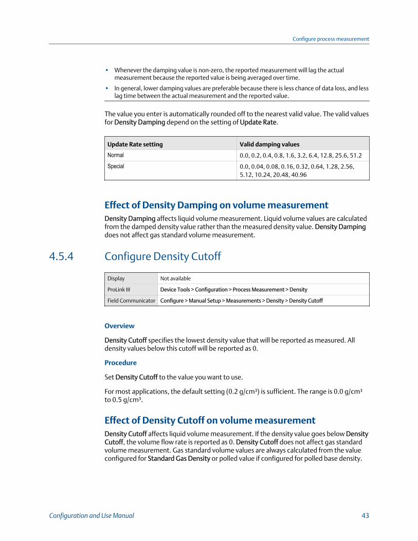
• Whenever the damping value is non-zero, the reported measurement will lag the actualmeasurement because the reported value is being averaged over time.
• In general, lower damping values are preferable because there is less chance of data loss, and lesslag time between the actual measurement and the reported value.
The value you enter is automatically rounded off to the nearest valid value. The valid valuesfor Density Damping depend on the setting of Update Rate.
Update Rate setting Valid damping values
Normal 0.0, 0.2, 0.4, 0.8, 1.6, 3.2, 6.4, 12.8, 25.6, 51.2
Special 0.0, 0.04, 0.08, 0.16, 0.32, 0.64, 1.28, 2.56,5.12, 10.24, 20.48, 40.96
Effect of Density Damping on volume measurementDensity Damping affects liquid volume measurement. Liquid volume values are calculatedfrom the damped density value rather than the measured density value. Density Dampingdoes not affect gas standard volume measurement.
4.5.4 Configure Density Cutoff
Display Not available
ProLink III Device Tools > Configuration > Process Measurement > Density
Field Communicator Configure > Manual Setup > Measurements > Density > Density Cutoff
Overview
Density Cutoff specifies the lowest density value that will be reported as measured. Alldensity values below this cutoff will be reported as 0.
Procedure
Set Density Cutoff to the value you want to use.
For most applications, the default setting (0.2 g/cm³) is sufficient. The range is 0.0 g/cm³to 0.5 g/cm³.
Effect of Density Cutoff on volume measurementDensity Cutoff affects liquid volume measurement. If the density value goes below DensityCutoff, the volume flow rate is reported as 0. Density Cutoff does not affect gas standardvolume measurement. Gas standard volume values are always calculated from the valueconfigured for Standard Gas Density or polled value if configured for polled base density.
Configure process measurement
Configuration and Use Manual 43
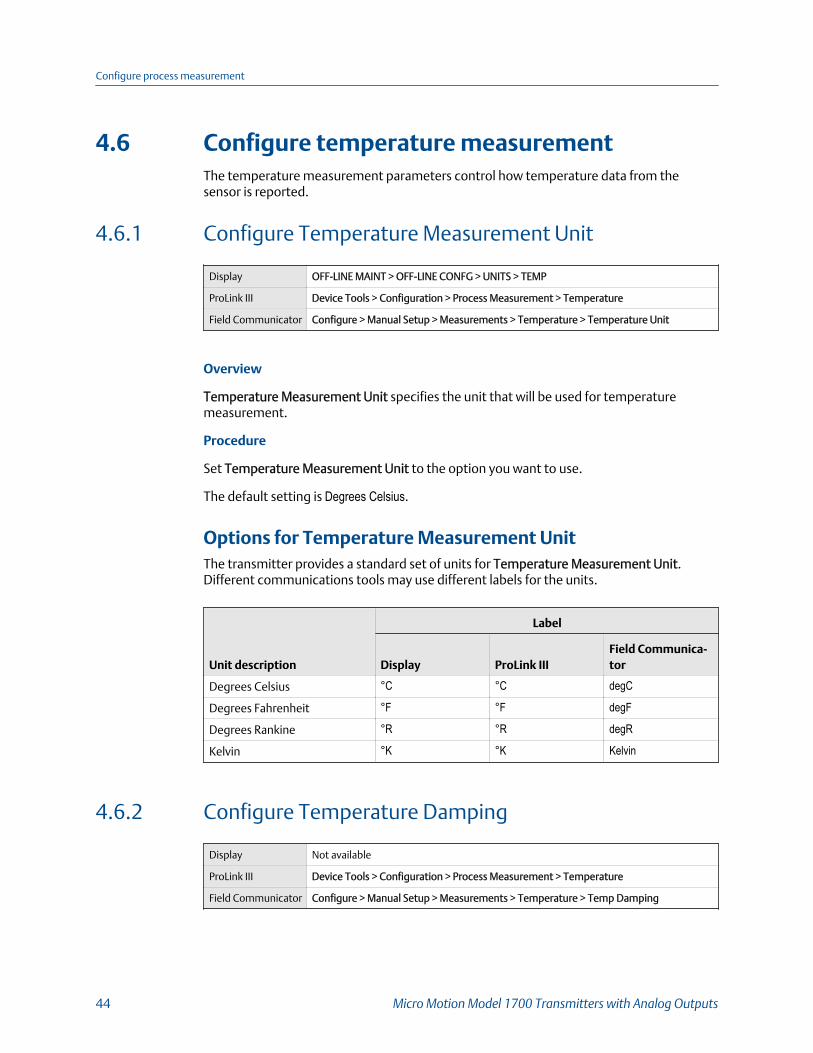
4.6 Configure temperature measurementThe temperature measurement parameters control how temperature data from thesensor is reported.
4.6.1 Configure Temperature Measurement Unit
Display OFF-LINE MAINT > OFF-LINE CONFG > UNITS > TEMP
ProLink III Device Tools > Configuration > Process Measurement > Temperature
Field Communicator Configure > Manual Setup > Measurements > Temperature > Temperature Unit
Overview
Temperature Measurement Unit specifies the unit that will be used for temperaturemeasurement.
Procedure
Set Temperature Measurement Unit to the option you want to use.
The default setting is Degrees Celsius.
Options for Temperature Measurement UnitThe transmitter provides a standard set of units for Temperature Measurement Unit.Different communications tools may use different labels for the units.
Unit description
Label
Display ProLink IIIField Communica-tor
Degrees Celsius °C °C degC
Degrees Fahrenheit °F °F degF
Degrees Rankine °R °R degR
Kelvin °K °K Kelvin
4.6.2 Configure Temperature Damping
Display Not available
ProLink III Device Tools > Configuration > Process Measurement > Temperature
Field Communicator Configure > Manual Setup > Measurements > Temperature > Temp Damping
Configure process measurement
44 Micro Motion Model 1700 Transmitters with Analog Outputs
Overview
Temperature Damping controls the amount of damping that will be applied to the linetemperature value, when the on-board temperature data is used (RTD).
Damping is used to smooth out small, rapid fluctuations in process measurement.Damping Value specifies the time period (in seconds) over which the transmitter willspread changes in the process variable. At the end of the interval, the internal value willreflect 63% of the change in the actual measured value.
TipTemperature Damping affects all process variables, compensations, and corrections that usetemperature data from the sensor.
Procedure
Enter the value you want to use for Temperature Damping.
The default value is 4.8 seconds. The range is 0.0 to 38.4 seconds.
Tips
• A high damping value makes the process variable appear smoother because the reported valuechanges slowly.
• A low damping value makes the process variable appear more erratic because the reported valuechanges more quickly.
• Whenever the damping value is non-zero, the reported measurement will lag the actualmeasurement because the reported value is being averaged over time.
• In general, lower damping values are preferable because there is less chance of data loss, and lesslag time between the actual measurement and the reported value.
The value you enter is automatically rounded off to the nearest valid value. Valid values forTemperature Damping are 0, 0.6, 1.2, 2.4, 4.8, … 38.4.
4.6.3 Effect of Temperature Damping on processmeasurementTemperature Damping affects all processes and algorithms that use temperature datafrom the internal sensor RTD.
Temperature compensation
Temperature compensation adjusts process measurement to compensate for the effect oftemperature on the sensor tubes.
4.6.4 Configure Temperature InputTemperature data from the on-board temperature sensor (RTD) is always available.Optionally, you can set up an external temperature device and use external temperaturedata.
Configure process measurement
Configuration and Use Manual 45
Choose Device Tools > Configuration > Process Measurement > Temperature > Source.
4.7 Configure pressure compensationPressure compensation adjusts process measurement to compensate for the pressureeffect on the sensor. The pressure effect is the change in the sensor’s sensitivity to flowand density caused by the difference between the calibration pressure and the processpressure.
TipNot all sensors or applications require pressure compensation. The pressure effect for a specificsensor model can be found in the product data sheet located at www.emerson.com. If you areuncertain about implementing pressure compensation, contact customer service.
Prerequisites
You will need the flow factor, density factor, and calibration pressure values for yoursensor.
• For the flow factor and density factor, see the product data sheet for your sensor.
• For the calibration pressure, see the calibration sheet for your sensor. If the data isunavailable, use 20 PSI.
4.7.1 Configure pressure compensation using ProLink III1. Choose Device Tools > Configuration > Process Measurement > Pressure
Compensation.
2. Set Pressure Compensation Status to Enabled.
3. Set Pressure Unit to the appropriate unit.
If you will use an external pressure value, set Pressure Unit to match the pressureunit used by the external pressure device.
4. Enter Flow Calibration Pressure for your sensor.
The calibration pressure is the pressure at which your sensor was calibrated, anddefines the pressure at which there is no pressure effect. If the data is unavailable,enter 20 PSI.
5. Enter Flow Factor for your sensor.
The flow factor is the percent change in the flow rate per PSI. When entering thevalue, reverse the sign.
Example: If the flow factor is 0.000004 % per PSI, enter −0.000004 % per PSI.
6. Enter Density Factor for your sensor.
The density factor is the change in fluid density, in g/cm3/PSI. When entering thevalue, reverse the sign.
Configure process measurement
46 Micro Motion Model 1700 Transmitters with Analog Outputs
Example:
If the density factor is 0.000006 g/cm3/PSI, enter −0.000006g/cm3/PSI.
7. Set Pressure Source to the method that the transmitter will use to obtain pressuredata.
Option Description
Poll for external value The transmitter will poll an external pressure device, usingHART protocol over the primary mA Output.
Fixed Value or Digital Communi-cations
The transmitter will use the pressure value that it reads frommemory.• Fixed Value: The configured value is used.• Digital Communications: A host writes transmitter data
to transmitter memory.
8. If you chose to poll for pressure data:
a. Select the Polling Slot to use.
b. Set Polling Control to Poll as Primary or Poll as Secondary, and click Apply.
Tip
• Poll as Primary: No other HART masters will be on the network.
• Poll as Secondary: Other HART masters will be on the network. The Field Communicatoris not a HART master.
c. Set External Device Tag to the HART tag of the external pressure device, and clickApply.
d. Ensure that the primary mA Output is wired to support HART communicationswith the external pressure device.
9. If you chose to use a fixed pressure value:
a. Set Fixed Value to the value to use, and click Apply
10. If you want to use digital communications, click Apply, then perform the necessaryhost programming and communications setup to write pressure data to thetransmitter at appropriate intervals.
Postrequisites
If you are using an external pressure value, verify the setup by checking the ExternalPressure value displayed in the Inputs area of the main window.
4.7.2 Configure pressure compensation using the FieldCommunicator1. Choose Online > Configure > Manual Setup > Measurements > External Pressure/
Temperature > Pressure.
Configure process measurement
Configuration and Use Manual 47
2. Set Pressure Compensation to Enabled.
3. Enter Flow Cal Pressure for your sensor.
The calibration pressure is the pressure at which your sensor was calibrated, anddefines the pressure at which there is no pressure effect. If the data is unavailable,enter 20 PSI.
4. Enter Flow Press Factor for your sensor.
The flow factor is the percent change in the flow rate per PSI. When entering thevalue, reverse the sign.
Example:
If the flow factor is 0.000004 % per PSI, enter −0.000004 % per PSI.
5. Enter Dens Press Factor for your sensor.
The density factor is the change in fluid density, in g/cm3/PSI. When entering thevalue, reverse the sign.
Example:
If the density factor is 0.000006 g/cm3/PSI, enter −0.000006g/cm3/PSI.
6. Determine how the transmitter will obtain pressure data, and perform the requiredsetup.
Option Setup
A user-configuredstatic pressure value
a. Set Pressure Unit to the desired unit.b. Set Compensation Pressure to the desired value.
Polling for pressure a. Ensure that the primary mA Output has been wired to supportHART polling.
b. Choose Online > Configure > Manual Setup > Measurements >External Pressure/Temperature > External Polling .
c. Set Poll Control to Poll As Primary Host or Poll as Secondary Host.d. Choose an unused polling slot.e. Set External Tag to the HART tag of the external pressure device.f. Set Polled Variable to Pressure.
Tip• Poll as Primary: No other HART masters will be on the network.• Poll as Secondary: Other HART masters will be on the network.
The Field Communicator is not a HART master.
A value written bydigital communica-tions
a. Set Pressure Unit to the desired unit.b. Perform the necessary host programming and communications
setup to write pressure data to the transmitter at appropriate in-tervals.
Configure process measurement
48 Micro Motion Model 1700 Transmitters with Analog Outputs
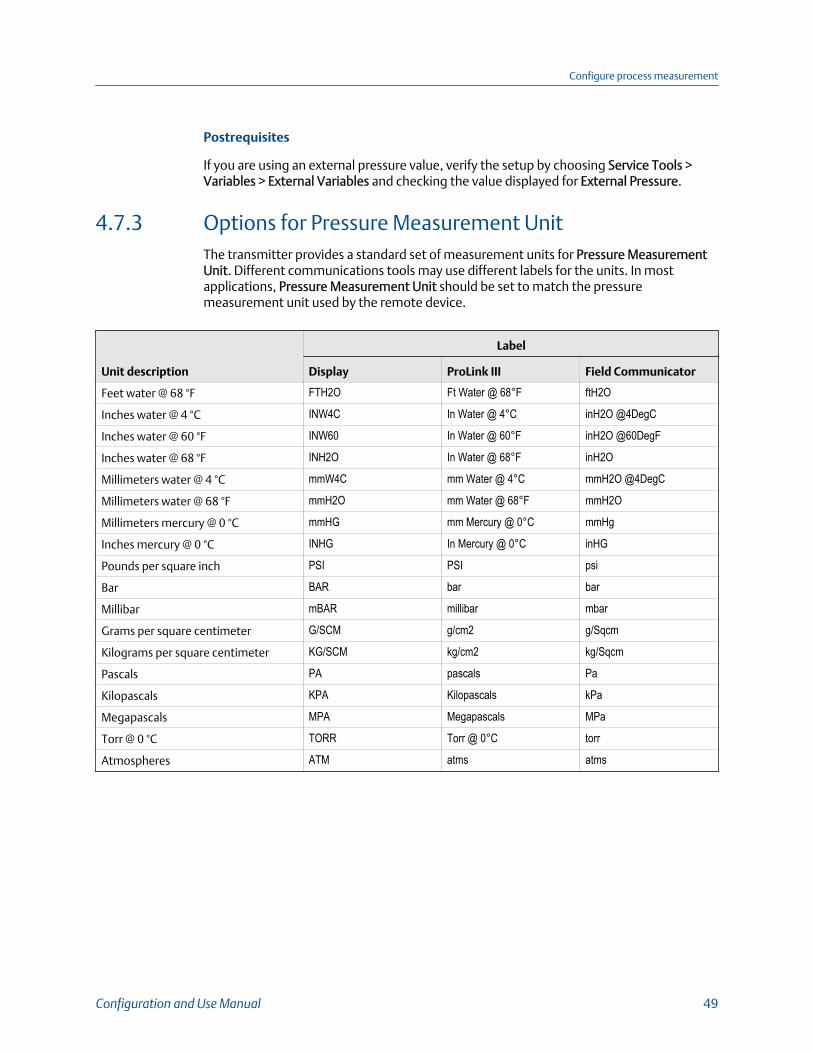
Postrequisites
If you are using an external pressure value, verify the setup by choosing Service Tools >Variables > External Variables and checking the value displayed for External Pressure.
4.7.3 Options for Pressure Measurement UnitThe transmitter provides a standard set of measurement units for Pressure MeasurementUnit. Different communications tools may use different labels for the units. In mostapplications, Pressure Measurement Unit should be set to match the pressuremeasurement unit used by the remote device.
Unit description
Label
Display ProLink III Field Communicator
Feet water @ 68 °F FTH2O Ft Water @ 68°F ftH2O
Inches water @ 4 °C INW4C In Water @ 4°C inH2O @4DegC
Inches water @ 60 °F INW60 In Water @ 60°F inH2O @60DegF
Inches water @ 68 °F INH2O In Water @ 68°F inH2O
Millimeters water @ 4 °C mmW4C mm Water @ 4°C mmH2O @4DegC
Millimeters water @ 68 °F mmH2O mm Water @ 68°F mmH2O
Millimeters mercury @ 0 °C mmHG mm Mercury @ 0°C mmHg
Inches mercury @ 0 °C INHG In Mercury @ 0°C inHG
Pounds per square inch PSI PSI psi
Bar BAR bar bar
Millibar mBAR millibar mbar
Grams per square centimeter G/SCM g/cm2 g/Sqcm
Kilograms per square centimeter KG/SCM kg/cm2 kg/Sqcm
Pascals PA pascals Pa
Kilopascals KPA Kilopascals kPa
Megapascals MPA Megapascals MPa
Torr @ 0 °C TORR Torr @ 0°C torr
Atmospheres ATM atms atms
Configure process measurement
Configuration and Use Manual 49

Configure process measurement
50 Micro Motion Model 1700 Transmitters with Analog Outputs
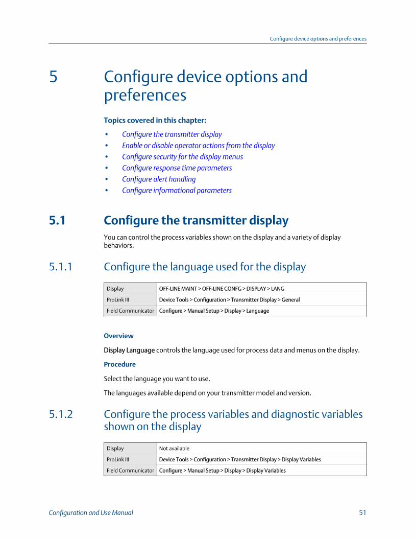
5 Configure device options andpreferencesTopics covered in this chapter:
• Configure the transmitter display
• Enable or disable operator actions from the display
• Configure security for the display menus
• Configure response time parameters
• Configure alert handling
• Configure informational parameters
5.1 Configure the transmitter displayYou can control the process variables shown on the display and a variety of displaybehaviors.
5.1.1 Configure the language used for the display
Display OFF-LINE MAINT > OFF-LINE CONFG > DISPLAY > LANG
ProLink III Device Tools > Configuration > Transmitter Display > General
Field Communicator Configure > Manual Setup > Display > Language
Overview
Display Language controls the language used for process data and menus on the display.
Procedure
Select the language you want to use.
The languages available depend on your transmitter model and version.
5.1.2 Configure the process variables and diagnostic variablesshown on the display
Display Not available
ProLink III Device Tools > Configuration > Transmitter Display > Display Variables
Field Communicator Configure > Manual Setup > Display > Display Variables
Configure device options and preferences
Configuration and Use Manual 51
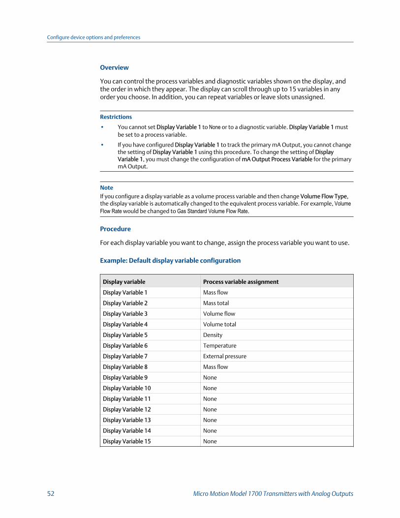
Overview
You can control the process variables and diagnostic variables shown on the display, andthe order in which they appear. The display can scroll through up to 15 variables in anyorder you choose. In addition, you can repeat variables or leave slots unassigned.
Restrictions
• You cannot set Display Variable 1 to None or to a diagnostic variable. Display Variable 1 mustbe set to a process variable.
• If you have configured Display Variable 1 to track the primary mA Output, you cannot changethe setting of Display Variable 1 using this procedure. To change the setting of DisplayVariable 1, you must change the configuration of mA Output Process Variable for the primarymA Output.
NoteIf you configure a display variable as a volume process variable and then change Volume Flow Type,the display variable is automatically changed to the equivalent process variable. For example, VolumeFlow Rate would be changed to Gas Standard Volume Flow Rate.
Procedure
For each display variable you want to change, assign the process variable you want to use.
Example: Default display variable configuration
Display variable Process variable assignment
Display Variable 1 Mass flow
Display Variable 2 Mass total
Display Variable 3 Volume flow
Display Variable 4 Volume total
Display Variable 5 Density
Display Variable 6 Temperature
Display Variable 7 External pressure
Display Variable 8 Mass flow
Display Variable 9 None
Display Variable 10 None
Display Variable 11 None
Display Variable 12 None
Display Variable 13 None
Display Variable 14 None
Display Variable 15 None
Configure device options and preferences
52 Micro Motion Model 1700 Transmitters with Analog Outputs

Configure Display Variable 1 to track the primary mA Output
Display OFF-LINE MAINT > OFF-LINE CONFG > DISPLY > VAR 1
ProLink III Device Tools > Configuration > Transmitter Display > Display Security
Field Communicator Configure > Manual Setup > Display > Display Variables
Overview
You can configure Display Variable 1 to track mA Output Process Variable for the primarymA Output. When tracking is enabled, you can control Display Variable 1 from the displaymenu.
TipThis feature is the only way to configure a display variable from the display menus, and it applies onlyto Display Variable 1.
Procedure
Configure Display Variable 1 to track the primary mA Output.
Display Variable 1 will automatically be set to match mA Output Process Variable for theprimary mA Output. If you change the configuration of mA Output Process Variable,Display Variable 1 will be updated automatically.
5.1.3 Configure the number of decimal places (precision)shown on the display
Display Not available
ProLink III Device Tools > Configuration > Transmitter Display > Display Variables
Field Communicator Configure > Manual Setup > Display > Decimal Places
Overview
You can specify the number of decimal places (precision) that are shown on the display foreach process variable or diagnostic variable. You can set the precision independently foreach variable.
The display precision does not affect the actual value of the variable or the value used incalculations.
Procedure
1. Select a variable.
2. Set Number of Decimal Places to the number of decimal places you want shownwhen the process variable or diagnostic variable appears on the display.
Configure device options and preferences
Configuration and Use Manual 53

For temperature and density process variables, the default value is 2 decimal places.For all other variables, the default value is 4 decimal places. The range is 0 to 5.
TipThe lower the precision, the greater the change must be for it to be reflected on the display.Do not set the precision too low or too high to be useful.
5.1.4 Configure the refresh rate of data shown on the display
Display OFF-LINE MAINT > OFF-LINE CONFG > DISPLAY > RATE
ProLink III Device Tools > Configuration > Transmitter Display > Display Variables
Field Communicator Configure > Manual Setup > Display > Display Variable Menu Features > Refresh Rate
Overview
You can set Refresh Rate to control how frequently data is refreshed on the display.
Procedure
Set Refresh Rate to the desired value.
The default value is 200 milliseconds. The range is 100 milliseconds to 10,000 milliseconds(10 seconds).
5.1.5 Enable or disable automatic scrolling through thedisplay variables
Display OFF-LINE MAINT > OFF-LINE CONFG > DISPLAY > AUTO SCRLL
ProLink III Device Tools > Configuration > Transmitter Display > General
Field Communicator Configure > Manual Setup > Display > Display Variable Menu Features > Auto Scroll
Overview
You can configure the display to automatically scroll through the configured displayvariables or to show a single display variable until the operator activates Scroll. When youset automatic scrolling, you can also configure the length of time each display variable isdisplayed.
Procedure
1. Enable or disable Auto Scroll as desired.
Configure device options and preferences
54 Micro Motion Model 1700 Transmitters with Analog Outputs
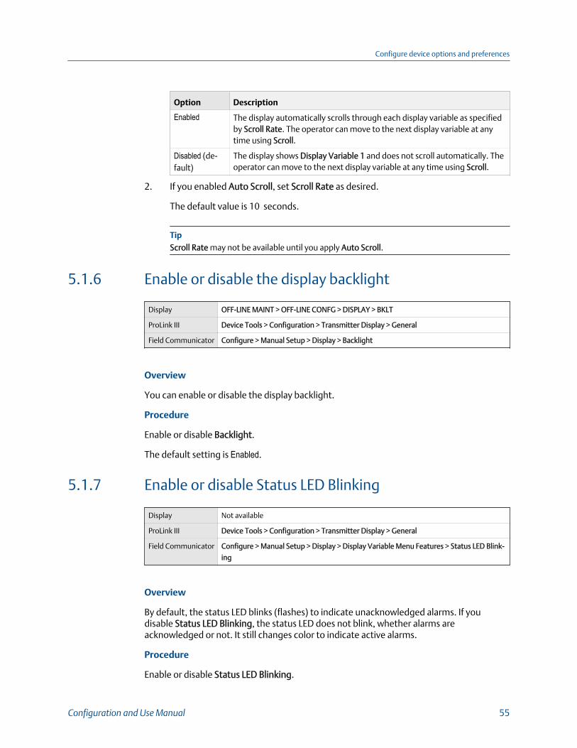
Option Description
Enabled The display automatically scrolls through each display variable as specifiedby Scroll Rate. The operator can move to the next display variable at anytime using Scroll.
Disabled (de-fault)
The display shows Display Variable 1 and does not scroll automatically. Theoperator can move to the next display variable at any time using Scroll.
2. If you enabled Auto Scroll, set Scroll Rate as desired.
The default value is 10 seconds.
TipScroll Rate may not be available until you apply Auto Scroll.
5.1.6 Enable or disable the display backlight
Display OFF-LINE MAINT > OFF-LINE CONFG > DISPLAY > BKLT
ProLink III Device Tools > Configuration > Transmitter Display > General
Field Communicator Configure > Manual Setup > Display > Backlight
Overview
You can enable or disable the display backlight.
Procedure
Enable or disable Backlight.
The default setting is Enabled.
5.1.7 Enable or disable Status LED Blinking
Display Not available
ProLink III Device Tools > Configuration > Transmitter Display > General
Field Communicator Configure > Manual Setup > Display > Display Variable Menu Features > Status LED Blink-
ing
Overview
By default, the status LED blinks (flashes) to indicate unacknowledged alarms. If youdisable Status LED Blinking, the status LED does not blink, whether alarms areacknowledged or not. It still changes color to indicate active alarms.
Procedure
Enable or disable Status LED Blinking.
Configure device options and preferences
Configuration and Use Manual 55
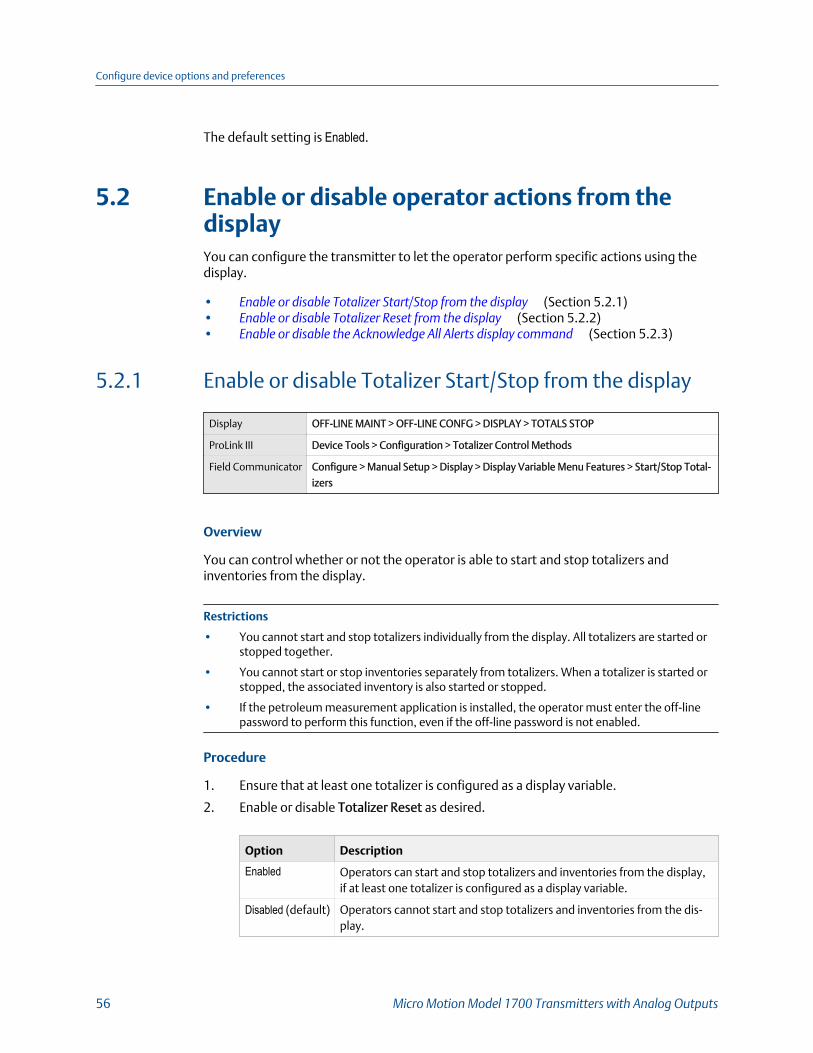
The default setting is Enabled.
5.2 Enable or disable operator actions from thedisplayYou can configure the transmitter to let the operator perform specific actions using thedisplay.
• Enable or disable Totalizer Start/Stop from the display (Section 5.2.1)• Enable or disable Totalizer Reset from the display (Section 5.2.2)• Enable or disable the Acknowledge All Alerts display command (Section 5.2.3)
5.2.1 Enable or disable Totalizer Start/Stop from the display
Display OFF-LINE MAINT > OFF-LINE CONFG > DISPLAY > TOTALS STOP
ProLink III Device Tools > Configuration > Totalizer Control Methods
Field Communicator Configure > Manual Setup > Display > Display Variable Menu Features > Start/Stop Total-
izers
Overview
You can control whether or not the operator is able to start and stop totalizers andinventories from the display.
Restrictions
• You cannot start and stop totalizers individually from the display. All totalizers are started orstopped together.
• You cannot start or stop inventories separately from totalizers. When a totalizer is started orstopped, the associated inventory is also started or stopped.
• If the petroleum measurement application is installed, the operator must enter the off-linepassword to perform this function, even if the off-line password is not enabled.
Procedure
1. Ensure that at least one totalizer is configured as a display variable.
2. Enable or disable Totalizer Reset as desired.
Option Description
Enabled Operators can start and stop totalizers and inventories from the display,if at least one totalizer is configured as a display variable.
Disabled (default) Operators cannot start and stop totalizers and inventories from the dis-play.
Configure device options and preferences
56 Micro Motion Model 1700 Transmitters with Analog Outputs

5.2.2 Enable or disable Totalizer Reset from the display
Display OFF-LINE MAINT > OFF-LINE CONFG > DISPLAY > TOTALS RESET
ProLink III Device Tools > Configuration > Totalizer Control Methods
Field Communicator Configure > Manual Setup > Display > Display Variable Menu Features > Totalizer Reset
Overview
You can configure whether or not the operator is able to reset totalizers from the display.
Restrictions
• This parameter does not apply to inventories. You cannot reset inventories from the display.
• You cannot use the display to reset all totalizers as a group. You must reset totalizersindividually.
• If the petroleum measurement application is installed, the operator must enter the off-linepassword to perform this function, even if the off-line password is not enabled.
Procedure
1. Ensure that the totalizers you want to reset have been configured as displayvariables.
If the totalizer is not configured as a display variable, the operator will not be able toreset it.
2. Enable or disable resetting the totalizer as desired.
Option Description
Enabled Operators can reset a totalizer from the display, if the totalizer is config-ured as a display variable.
Disabled (default) Operators cannot reset totalizers from the display.
5.2.3 Enable or disable the Acknowledge All Alerts displaycommand
Display OFF-LINE MAINT > OFF-LINE CONFG > DISPLAY > ALARM
ProLink III Device Tools > Configuration > Transmitter Display > Ack All
Field Communicator Configure > Manual Setup > Display > Offline Variable Menu Features > Acknowledge All
Overview
You can configure whether or not the operator can use a single command to acknowledgeall alerts from the display.
Configure device options and preferences
Configuration and Use Manual 57
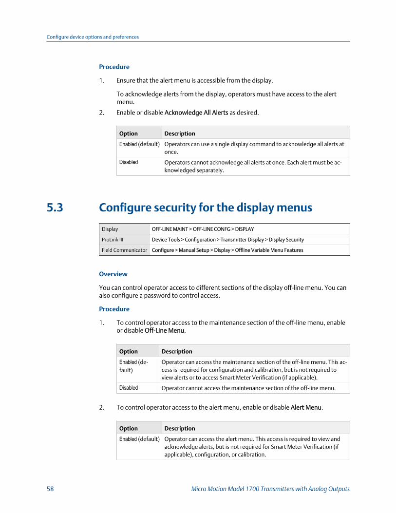
Procedure
1. Ensure that the alert menu is accessible from the display.
To acknowledge alerts from the display, operators must have access to the alertmenu.
2. Enable or disable Acknowledge All Alerts as desired.
Option Description
Enabled (default) Operators can use a single display command to acknowledge all alerts atonce.
Disabled Operators cannot acknowledge all alerts at once. Each alert must be ac-knowledged separately.
5.3 Configure security for the display menus
Display OFF-LINE MAINT > OFF-LINE CONFG > DISPLAY
ProLink III Device Tools > Configuration > Transmitter Display > Display Security
Field Communicator Configure > Manual Setup > Display > Offline Variable Menu Features
Overview
You can control operator access to different sections of the display off-line menu. You canalso configure a password to control access.
Procedure
1. To control operator access to the maintenance section of the off-line menu, enableor disable Off-Line Menu.
Option Description
Enabled (de-fault)
Operator can access the maintenance section of the off-line menu. This ac-cess is required for configuration and calibration, but is not required toview alerts or to access Smart Meter Verification (if applicable).
Disabled Operator cannot access the maintenance section of the off-line menu.
2. To control operator access to the alert menu, enable or disable Alert Menu.
Option Description
Enabled (default) Operator can access the alert menu. This access is required to view andacknowledge alerts, but is not required for Smart Meter Verification (ifapplicable), configuration, or calibration.
Configure device options and preferences
58 Micro Motion Model 1700 Transmitters with Analog Outputs
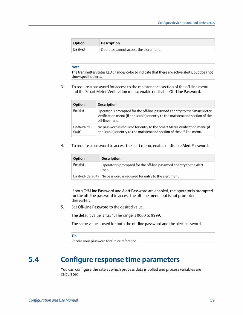
Option Description
Disabled Operator cannot access the alert menu.
NoteThe transmitter status LED changes color to indicate that there are active alerts, but does notshow specific alerts.
3. To require a password for access to the maintenance section of the off-line menuand the Smart Meter Verification menu, enable or disable Off-Line Password.
Option Description
Enabled Operator is prompted for the off-line password at entry to the Smart MeterVerification menu (if applicable) or entry to the maintenance section of theoff-line menu.
Disabled (de-fault)
No password is required for entry to the Smart Meter Verification menu (ifapplicable) or entry to the maintenance section of the off-line menu.
4. To require a password to access the alert menu, enable or disable Alert Password.
Option Description
Enabled Operator is prompted for the off-line password at entry to the alertmenu.
Disabled (default) No password is required for entry to the alert menu.
If both Off-Line Password and Alert Password are enabled, the operator is promptedfor the off-line password to access the off-line menu, but is not promptedthereafter.
5. Set Off-Line Password to the desired value.
The default value is 1234. The range is 0000 to 9999.
The same value is used for both the off-line password and the alert password.
TipRecord your password for future reference.
5.4 Configure response time parametersYou can configure the rate at which process data is polled and process variables arecalculated.
Configure device options and preferences
Configuration and Use Manual 59
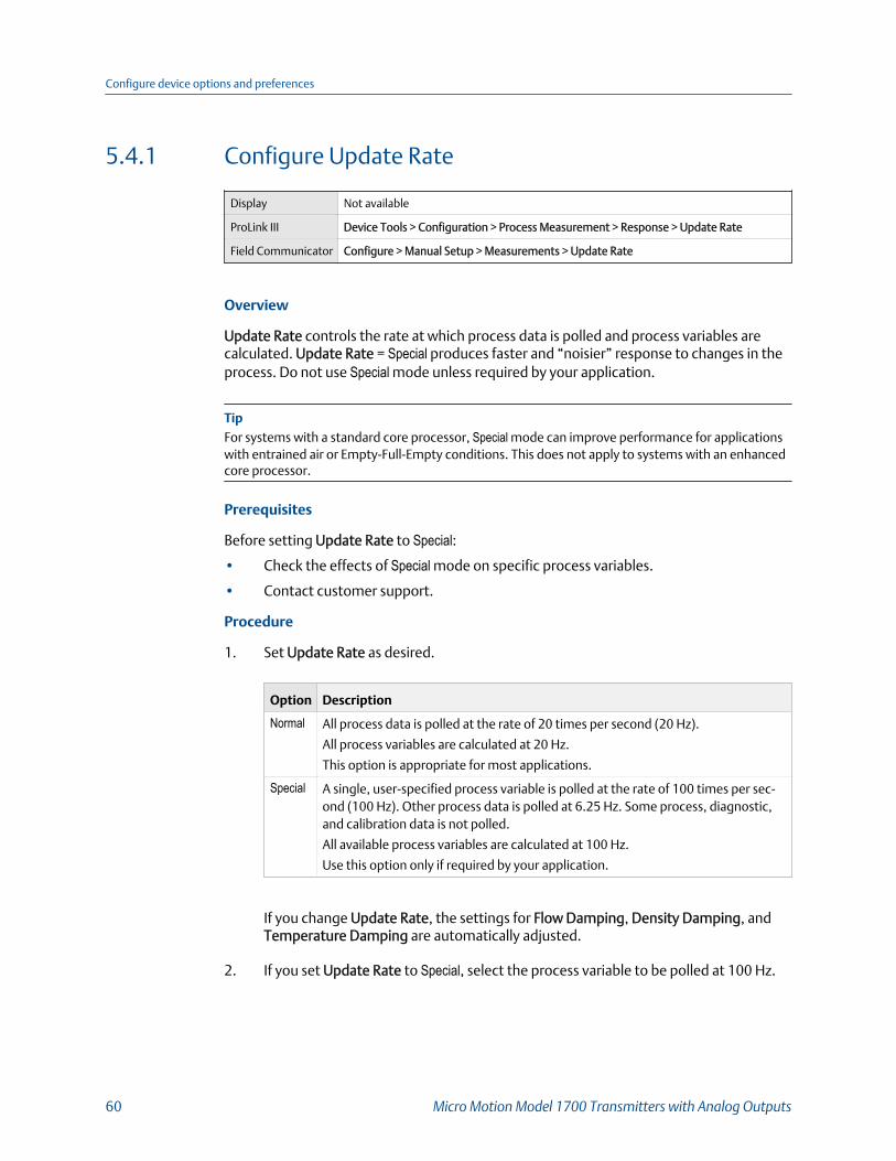
5.4.1 Configure Update Rate
Display Not available
ProLink III Device Tools > Configuration > Process Measurement > Response > Update Rate
Field Communicator Configure > Manual Setup > Measurements > Update Rate
Overview
Update Rate controls the rate at which process data is polled and process variables arecalculated. Update Rate = Special produces faster and “noisier” response to changes in theprocess. Do not use Special mode unless required by your application.
TipFor systems with a standard core processor, Special mode can improve performance for applicationswith entrained air or Empty-Full-Empty conditions. This does not apply to systems with an enhancedcore processor.
Prerequisites
Before setting Update Rate to Special:• Check the effects of Special mode on specific process variables.
• Contact customer support.
Procedure
1. Set Update Rate as desired.
Option Description
Normal All process data is polled at the rate of 20 times per second (20 Hz).
All process variables are calculated at 20 Hz.
This option is appropriate for most applications.
Special A single, user-specified process variable is polled at the rate of 100 times per sec-ond (100 Hz). Other process data is polled at 6.25 Hz. Some process, diagnostic,and calibration data is not polled.
All available process variables are calculated at 100 Hz.
Use this option only if required by your application.
If you change Update Rate, the settings for Flow Damping, Density Damping, andTemperature Damping are automatically adjusted.
2. If you set Update Rate to Special, select the process variable to be polled at 100 Hz.
Configure device options and preferences
60 Micro Motion Model 1700 Transmitters with Analog Outputs
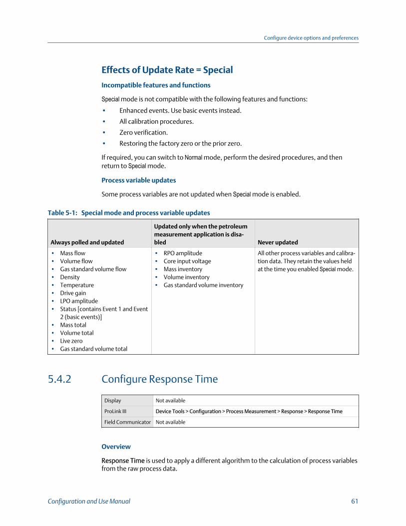
Effects of Update Rate = Special
Incompatible features and functions
Special mode is not compatible with the following features and functions:
• Enhanced events. Use basic events instead.
• All calibration procedures.
• Zero verification.
• Restoring the factory zero or the prior zero.
If required, you can switch to Normal mode, perform the desired procedures, and thenreturn to Special mode.
Process variable updates
Some process variables are not updated when Special mode is enabled.
Special mode and process variable updatesTable 5-1:
Always polled and updated
Updated only when the petroleummeasurement application is disa-bled Never updated
• Mass flow• Volume flow• Gas standard volume flow• Density• Temperature• Drive gain• LPO amplitude• Status [contains Event 1 and Event
2 (basic events)]• Mass total• Volume total• Live zero• Gas standard volume total
• RPO amplitude• Core input voltage• Mass inventory• Volume inventory• Gas standard volume inventory
All other process variables and calibra-tion data. They retain the values heldat the time you enabled Special mode.
5.4.2 Configure Response Time
Display Not available
ProLink III Device Tools > Configuration > Process Measurement > Response > Response Time
Field Communicator Not available
Overview
Response Time is used to apply a different algorithm to the calculation of process variablesfrom the raw process data.
Configure device options and preferences
Configuration and Use Manual 61
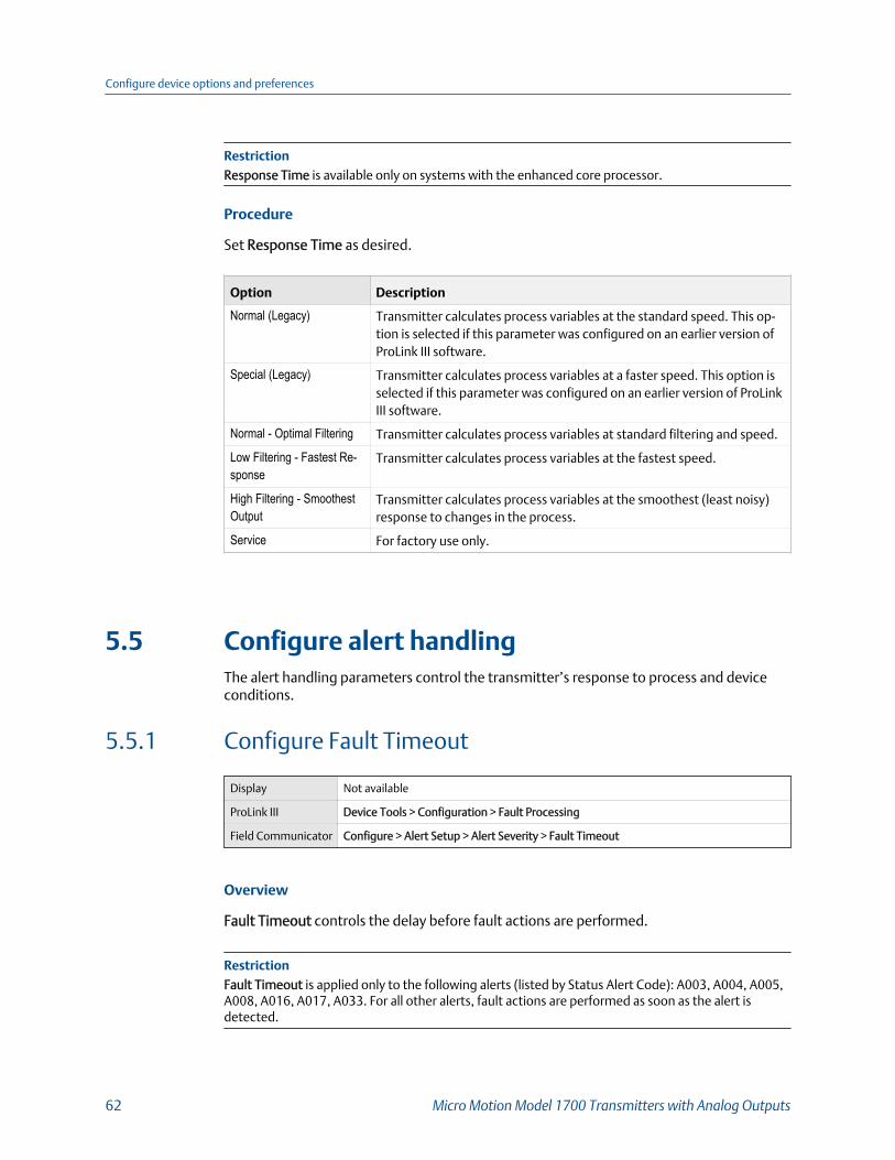
RestrictionResponse Time is available only on systems with the enhanced core processor.
Procedure
Set Response Time as desired.
Option Description
Normal (Legacy) Transmitter calculates process variables at the standard speed. This op-tion is selected if this parameter was configured on an earlier version ofProLink III software.
Special (Legacy) Transmitter calculates process variables at a faster speed. This option isselected if this parameter was configured on an earlier version of ProLinkIII software.
Normal - Optimal Filtering Transmitter calculates process variables at standard filtering and speed.
Low Filtering - Fastest Re-sponse
Transmitter calculates process variables at the fastest speed.
High Filtering - SmoothestOutput
Transmitter calculates process variables at the smoothest (least noisy)response to changes in the process.
Service For factory use only.
5.5 Configure alert handlingThe alert handling parameters control the transmitter’s response to process and deviceconditions.
5.5.1 Configure Fault Timeout
Display Not available
ProLink III Device Tools > Configuration > Fault Processing
Field Communicator Configure > Alert Setup > Alert Severity > Fault Timeout
Overview
Fault Timeout controls the delay before fault actions are performed.
RestrictionFault Timeout is applied only to the following alerts (listed by Status Alert Code): A003, A004, A005,A008, A016, A017, A033. For all other alerts, fault actions are performed as soon as the alert isdetected.
Configure device options and preferences
62 Micro Motion Model 1700 Transmitters with Analog Outputs

Procedure
Set Fault Timeout as desired.
The default value is 0 seconds. The range is 0 to 60 seconds.
If you set Fault Timeout to 0, fault actions are performed as soon as the alert condition isdetected.
The fault timeout period begins when the transmitter detects an alert condition. Duringthe fault timeout period, the transmitter continues to report its last valid measurements.
If the fault timeout period expires while the alert is still active, the fault actions areperformed. If the alert condition clears before the fault timeout expires, no fault actionsare performed.
5.5.2 Configure Status Alert Severity
Display Not available
ProLink III Device Tools > Configuration > Alert Severity
Field Communicator Configure > Alert Setup > Alert Severity > Set Alert Severity
Overview
Use Status Alert Severity to control the fault actions that the transmitter performs when itdetects an alert condition.
Restrictions
• For some alerts, Status Alert Severity is not configurable.
• For some alerts, Status Alert Severity can be set only to two of the three options.
TipUse the default settings for Status Alert Severity unless you have a specific requirement to changethem.
Procedure
1. Select a status alert.
2. For the selected status alert, set Status Alert Severity as desired.
Configure device options and preferences
Configuration and Use Manual 63
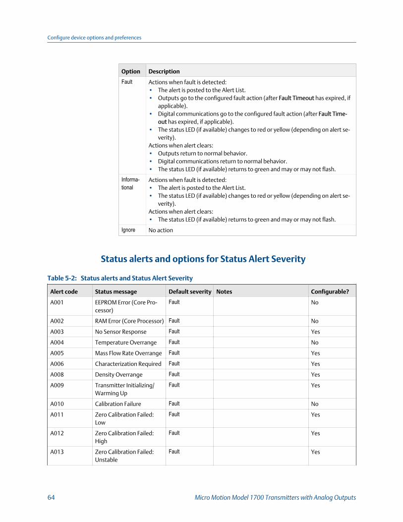
Option Description
Fault Actions when fault is detected:• The alert is posted to the Alert List.• Outputs go to the configured fault action (after Fault Timeout has expired, if
applicable).• Digital communications go to the configured fault action (after Fault Time-
out has expired, if applicable).• The status LED (if available) changes to red or yellow (depending on alert se-
verity).Actions when alert clears:• Outputs return to normal behavior.• Digital communications return to normal behavior.• The status LED (if available) returns to green and may or may not flash.
Informa-tional
Actions when fault is detected:• The alert is posted to the Alert List.• The status LED (if available) changes to red or yellow (depending on alert se-
verity).Actions when alert clears:• The status LED (if available) returns to green and may or may not flash.
Ignore No action
Status alerts and options for Status Alert Severity
Status alerts and Status Alert Severity Table 5-2:
Alert code Status message Default severity Notes Configurable?
A001 EEPROM Error (Core Pro-cessor)
Fault No
A002 RAM Error (Core Processor) Fault No
A003 No Sensor Response Fault Yes
A004 Temperature Overrange Fault No
A005 Mass Flow Rate Overrange Fault Yes
A006 Characterization Required Fault Yes
A008 Density Overrange Fault Yes
A009 Transmitter Initializing/Warming Up
Fault Yes
A010 Calibration Failure Fault No
A011 Zero Calibration Failed:Low
Fault Yes
A012 Zero Calibration Failed:High
Fault Yes
A013 Zero Calibration Failed:Unstable
Fault Yes
Configure device options and preferences
64 Micro Motion Model 1700 Transmitters with Analog Outputs
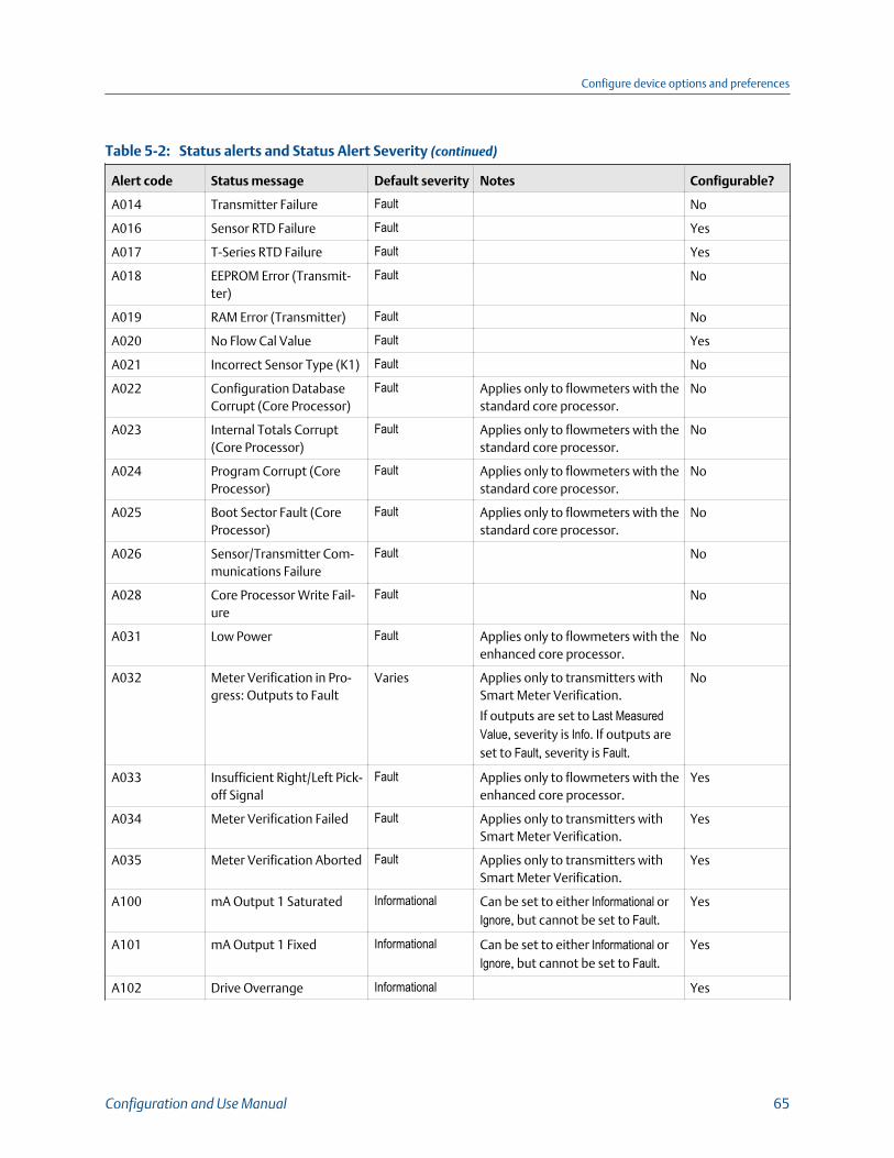
Status alerts and Status Alert Severity (continued)Table 5-2:
Alert code Status message Default severity Notes Configurable?
A014 Transmitter Failure Fault No
A016 Sensor RTD Failure Fault Yes
A017 T-Series RTD Failure Fault Yes
A018 EEPROM Error (Transmit-ter)
Fault No
A019 RAM Error (Transmitter) Fault No
A020 No Flow Cal Value Fault Yes
A021 Incorrect Sensor Type (K1) Fault No
A022 Configuration DatabaseCorrupt (Core Processor)
Fault Applies only to flowmeters with thestandard core processor.
No
A023 Internal Totals Corrupt(Core Processor)
Fault Applies only to flowmeters with thestandard core processor.
No
A024 Program Corrupt (CoreProcessor)
Fault Applies only to flowmeters with thestandard core processor.
No
A025 Boot Sector Fault (CoreProcessor)
Fault Applies only to flowmeters with thestandard core processor.
No
A026 Sensor/Transmitter Com-munications Failure
Fault No
A028 Core Processor Write Fail-ure
Fault No
A031 Low Power Fault Applies only to flowmeters with theenhanced core processor.
No
A032 Meter Verification in Pro-gress: Outputs to Fault
Varies Applies only to transmitters withSmart Meter Verification.
If outputs are set to Last MeasuredValue, severity is Info. If outputs areset to Fault, severity is Fault.
No
A033 Insufficient Right/Left Pick-off Signal
Fault Applies only to flowmeters with theenhanced core processor.
Yes
A034 Meter Verification Failed Fault Applies only to transmitters withSmart Meter Verification.
Yes
A035 Meter Verification Aborted Fault Applies only to transmitters withSmart Meter Verification.
Yes
A100 mA Output 1 Saturated Informational Can be set to either Informational orIgnore, but cannot be set to Fault.
Yes
A101 mA Output 1 Fixed Informational Can be set to either Informational orIgnore, but cannot be set to Fault.
Yes
A102 Drive Overrange Informational Yes
Configure device options and preferences
Configuration and Use Manual 65
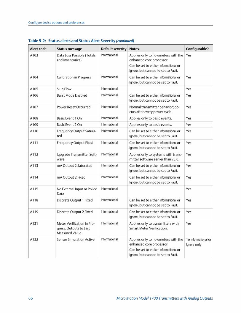
Status alerts and Status Alert Severity (continued)Table 5-2:
Alert code Status message Default severity Notes Configurable?
A103 Data Loss Possible (Totalsand Inventories)
Informational Applies only to flowmeters with theenhanced core processor.
Can be set to either Informational orIgnore, but cannot be set to Fault.
Yes
A104 Calibration in Progress Informational Can be set to either Informational orIgnore, but cannot be set to Fault.
Yes
A105 Slug Flow Informational Yes
A106 Burst Mode Enabled Informational Can be set to either Informational orIgnore, but cannot be set to Fault.
Yes
A107 Power Reset Occurred Informational Normal transmitter behavior; oc-curs after every power cycle.
Yes
A108 Basic Event 1 On Informational Applies only to basic events. Yes
A109 Basic Event 2 On Informational Applies only to basic events. Yes
A110 Frequency Output Satura-ted
Informational Can be set to either Informational orIgnore, but cannot be set to Fault.
Yes
A111 Frequency Output Fixed Informational Can be set to either Informational orIgnore, but cannot be set to Fault.
Yes
A112 Upgrade Transmitter Soft-ware
Informational Applies only to systems with trans-mitter software earlier than v5.0.
Yes
A113 mA Output 2 Saturated Informational Can be set to either Informational orIgnore, but cannot be set to Fault.
Yes
A114 mA Output 2 Fixed Informational Can be set to either Informational orIgnore, but cannot be set to Fault.
Yes
A115 No External Input or PolledData
Informational Yes
A118 Discrete Output 1 Fixed Informational Can be set to either Informational orIgnore, but cannot be set to Fault.
Yes
A119 Discrete Output 2 Fixed Informational Can be set to either Informational orIgnore, but cannot be set to Fault.
Yes
A131 Meter Verification in Pro-gress: Outputs to LastMeasured Value
Informational Applies only to transmitters withSmart Meter Verification.
Yes
A132 Sensor Simulation Active Informational Applies only to flowmeters with theenhanced core processor.
Can be set to either Informational orIgnore, but cannot be set to Fault.
To Informational orIgnore only
Configure device options and preferences
66 Micro Motion Model 1700 Transmitters with Analog Outputs
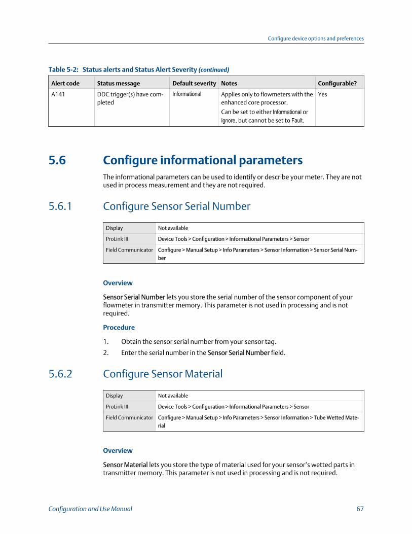
Status alerts and Status Alert Severity (continued)Table 5-2:
Alert code Status message Default severity Notes Configurable?
A141 DDC trigger(s) have com-pleted
Informational Applies only to flowmeters with theenhanced core processor.
Can be set to either Informational orIgnore, but cannot be set to Fault.
Yes
5.6 Configure informational parametersThe informational parameters can be used to identify or describe your meter. They are notused in process measurement and they are not required.
5.6.1 Configure Sensor Serial Number
Display Not available
ProLink III Device Tools > Configuration > Informational Parameters > Sensor
Field Communicator Configure > Manual Setup > Info Parameters > Sensor Information > Sensor Serial Num-
ber
Overview
Sensor Serial Number lets you store the serial number of the sensor component of yourflowmeter in transmitter memory. This parameter is not used in processing and is notrequired.
Procedure
1. Obtain the sensor serial number from your sensor tag.
2. Enter the serial number in the Sensor Serial Number field.
5.6.2 Configure Sensor Material
Display Not available
ProLink III Device Tools > Configuration > Informational Parameters > Sensor
Field Communicator Configure > Manual Setup > Info Parameters > Sensor Information > Tube Wetted Mate-
rial
Overview
Sensor Material lets you store the type of material used for your sensor’s wetted parts intransmitter memory. This parameter is not used in processing and is not required.
Configure device options and preferences
Configuration and Use Manual 67

Procedure
1. Obtain the material used for your sensor’s wetted parts from the documentsshipped with your sensor, or from a code in the sensor model number.
To interpret the model number, refer to the product data sheet for your sensor.
2. Set Sensor Material to the appropriate option.
5.6.3 Configure Sensor Liner Material
Display Not available
ProLink III Device Tools > Configuration > Informational Parameters > Sensor
Field Communicator Configure > Manual Setup > Info Parameters > Sensor Information > Tube Lining
Overview
Sensor Liner Material lets you store the type of material used for your sensor liner intransmitter memory. This parameter is not used in processing and is not required.
Procedure
1. Obtain your sensor’s liner material from the documents shipped with your sensor, orfrom a code in the sensor model number.
To interpret the model number, refer to the product data sheet for your sensor.
2. Set Sensor Liner Material to the appropriate option.
5.6.4 Configure Sensor Flange Type
Display Not available
ProLink III Device Tools > Configuration > Informational Parameters > Sensor
Field Communicator Configure > Manual Setup > Info Parameters > Sensor Information > Sensor Flange
Overview
Sensor Flange Type lets you store your sensor’s flange type in transmitter memory. Thisparameter is not used in processing and is not required.
Procedure
1. Obtain your sensor’s flange type from the documents shipped with your sensor, orfrom a code in the sensor model number.
To interpret the model number, refer to the product data sheet for your sensor.
2. Set Sensor Flange Type to the appropriate option.
Configure device options and preferences
68 Micro Motion Model 1700 Transmitters with Analog Outputs
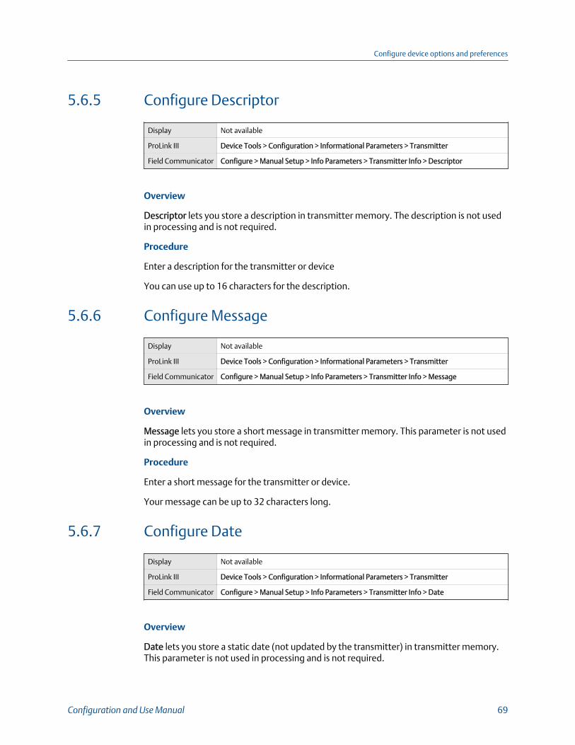
5.6.5 Configure Descriptor
Display Not available
ProLink III Device Tools > Configuration > Informational Parameters > Transmitter
Field Communicator Configure > Manual Setup > Info Parameters > Transmitter Info > Descriptor
Overview
Descriptor lets you store a description in transmitter memory. The description is not usedin processing and is not required.
Procedure
Enter a description for the transmitter or device
You can use up to 16 characters for the description.
5.6.6 Configure Message
Display Not available
ProLink III Device Tools > Configuration > Informational Parameters > Transmitter
Field Communicator Configure > Manual Setup > Info Parameters > Transmitter Info > Message
Overview
Message lets you store a short message in transmitter memory. This parameter is not usedin processing and is not required.
Procedure
Enter a short message for the transmitter or device.
Your message can be up to 32 characters long.
5.6.7 Configure Date
Display Not available
ProLink III Device Tools > Configuration > Informational Parameters > Transmitter
Field Communicator Configure > Manual Setup > Info Parameters > Transmitter Info > Date
Overview
Date lets you store a static date (not updated by the transmitter) in transmitter memory.This parameter is not used in processing and is not required.
Configure device options and preferences
Configuration and Use Manual 69

Procedure
Enter the date you want to use, in the form mm/dd/yyyy.
TipProLink III provides a calendar tool to help you select the date.
Configure device options and preferences
70 Micro Motion Model 1700 Transmitters with Analog Outputs
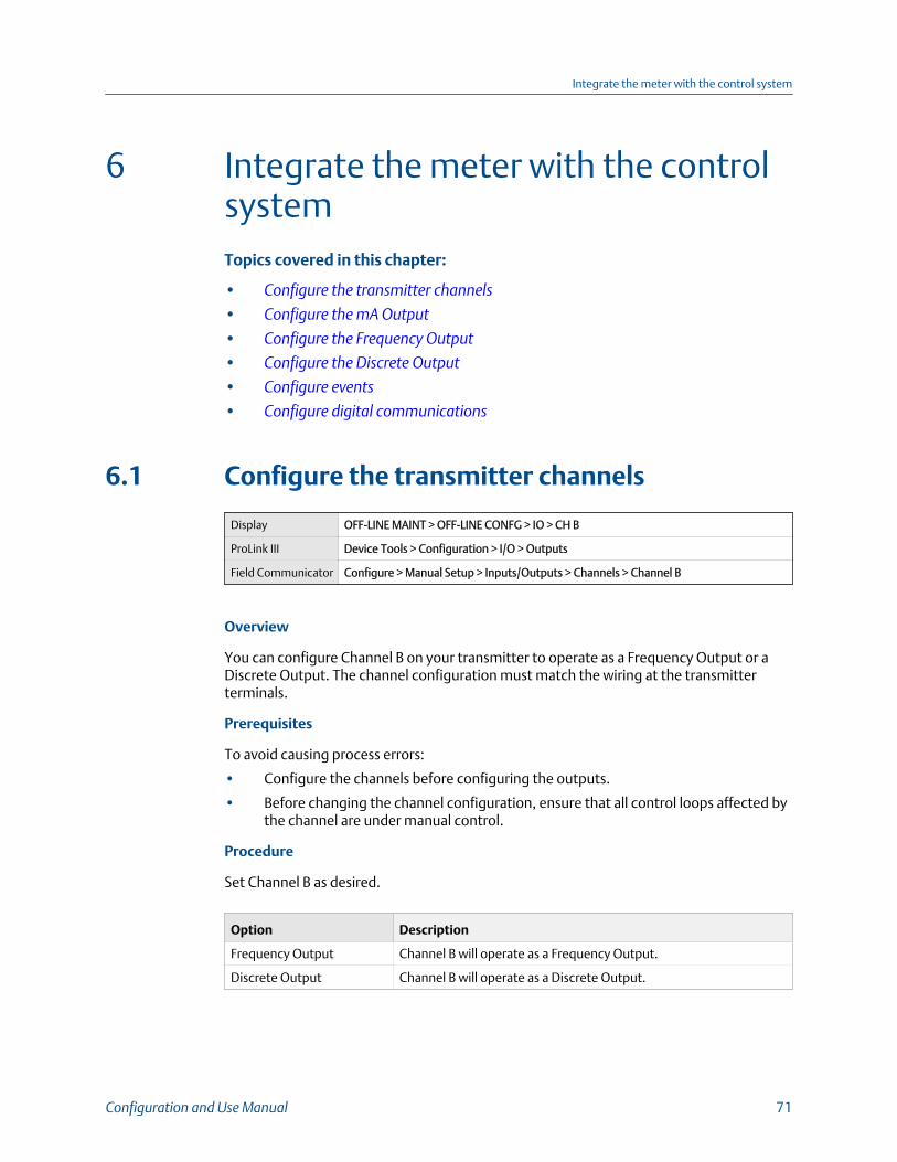
6 Integrate the meter with the controlsystemTopics covered in this chapter:
• Configure the transmitter channels
• Configure the mA Output
• Configure the Frequency Output
• Configure the Discrete Output
• Configure events
• Configure digital communications
6.1 Configure the transmitter channels
Display OFF-LINE MAINT > OFF-LINE CONFG > IO > CH B
ProLink III Device Tools > Configuration > I/O > Outputs
Field Communicator Configure > Manual Setup > Inputs/Outputs > Channels > Channel B
Overview
You can configure Channel B on your transmitter to operate as a Frequency Output or aDiscrete Output. The channel configuration must match the wiring at the transmitterterminals.
Prerequisites
To avoid causing process errors:
• Configure the channels before configuring the outputs.
• Before changing the channel configuration, ensure that all control loops affected bythe channel are under manual control.
Procedure
Set Channel B as desired.
Option Description
Frequency Output Channel B will operate as a Frequency Output.
Discrete Output Channel B will operate as a Discrete Output.
Integrate the meter with the control system
Configuration and Use Manual 71
Postrequisites
For each channel that you configured, perform or verify the corresponding input or outputconfiguration. When the configuration of a channel is changed, the channel’s behavior willbe controlled by the configuration that is stored for the selected input or output type, andthe stored configuration may not be appropriate for your process.
After verifying channel and output configuration, return the control loop to automaticcontrol.
6.2 Configure the mA OutputThe mA Output is used to report the configured process variable. The mA Outputparameters control how the process variable is reported.
Your transmitter has one mA Output: Channel A.
RestrictionThe process variable assigned to the primary mA Output is automatically assigned to the FrequencyOutput. You cannot assign a different process variable.
ImportantWhenever you change an mA Output parameter, verify all other mA Output parameters beforereturning the meter to service. In some situations, the transmitter automatically loads a set of storedvalues, and these values may not be appropriate for your application.
6.2.1 Configure mA Output Process Variable
Display OFF-LINE MAINT > OFF-LINE CONFG > IO > CH A > AO
ProLink III Device Tools > Configuration > I/O > Outputs > mA Output
Field Communicator Configure > Manual Setup > Inputs/Outputs > mA Output
Overview
Use mA Output Process Variable to select the variable that is reported over the mA Output.This variable is applied automatically to the Frequency Output.
Prerequisites
• If you plan to configure the output to report volume flow, ensure that you have setVolume Flow Type as desired: Liquid or Gas Standard Volume.
• If you are using the HART variables, be aware that changing the configuration of mAOutput Process Variable will change the configuration of the HART Primary Variable(PV) and the HART Tertiary Variable (TV).
Integrate the meter with the control system
72 Micro Motion Model 1700 Transmitters with Analog Outputs
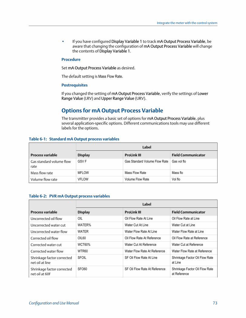
• If you have configured Display Variable 1 to track mA Output Process Variable, beaware that changing the configuration of mA Output Process Variable will changethe contents of Display Variable 1.
Procedure
Set mA Output Process Variable as desired.
The default setting is Mass Flow Rate.
Postrequisites
If you changed the setting of mA Output Process Variable, verify the settings of LowerRange Value (LRV) and Upper Range Value (URV).
Options for mA Output Process VariableThe transmitter provides a basic set of options for mA Output Process Variable, plusseveral application-specific options. Different communications tools may use differentlabels for the options.
Standard mA Output process variablesTable 6-1:
Process variable
Label
Display ProLink III Field Communicator
Gas standard volume flowrate
GSV F Gas Standard Volume Flow Rate Gas vol flo
Mass flow rate MFLOW Mass Flow Rate Mass flo
Volume flow rate VFLOW Volume Flow Rate Vol flo
PVR mA Output process variablesTable 6-2:
Process variable
Label
Display ProLink III Field Communicator
Uncorrected oil flow OIL Oil Flow Rate At Line Oil Flow Rate at Line
Uncorrected water cut WATER% Water Cut At Line Water Cut at Line
Uncorrected water flow WATER Water Flow Rate At Line Water Flow Rate at Line
Corrected oil flow OIL60 Oil Flow Rate At Reference Oil Flow Rate at Reference
Corrected water cut WCT60% Water Cut At Reference Water Cut at Reference
Corrected water flow WTR60 Water Flow Rate At Reference Water Flow Rate at Reference
Shrinkage factor correctednet oil at line
SFOIL SF Oil Flow Rate At Line Shrinkage Factor Oil Flow Rateat Line
Shrinkage factor correctednet oil at 60F
SFO60 SF Oil Flow Rate At Reference Shrinkage Factor Oil Flow Rateat Reference
Integrate the meter with the control system
Configuration and Use Manual 73

PVR mA Output process variables (continued)Table 6-2:
Process variable
Label
Display ProLink III Field Communicator
Shrinkage factor correctedvolume of mix at 60F
SFM60 SF Volume Flow Rate At Refer-ence
Shrinkage Factor Volume FlowRate at Reference
6.2.2 Configure Lower Range Value (LRV) and Upper RangeValue (URV)
Display • OFF-LINE MAINT > OFF-LINE CONFG > IO > CH A > 4 mA
• OFF-LINE MAINT > OFF-LINE CONFG > IO > CH A > 20 mA
ProLink III Device Tools > Configuration > I/O > Outputs > mA Output
Field Communicator • Configure > Manual Setup > Inputs/Outputs > mA Output > mA Output Settings > PV
LRV
• Configure > Manual Setup > Inputs/Outputs > mA Output > mA Output Settings > PV
URV
Overview
The Lower Range Value (LRV) and Upper Range Value (URV) are used to scale the mAOutput, that is, to define the relationship between mA Output Process Variable and themA Output level.
NoteFor transmitter software v5.0 and later, if you change LRV and URV from the factory default values,and you later change mA Output Process Variable, LRV and URV will not reset to the default values.
Prerequisites
Ensure that mA Output Process Variable is set to the desired process variable. Each processvariable has its own set of LRV and URV values. When you change the values of LRV andURV, you are configuring values for the currently assigned mA Output process variable.
Ensure that the measurement unit for the configured process variable has been set asdesired.
Procedure
Set LRV and URV as desired.
• LRVis the value of mA Output Process Variable represented by an output of 4 mA. Thedefault value for LRV depends on the setting of mA Output Process Variable. Enter LRVin the measurement units that are configured for mA Output Process Variable.
Integrate the meter with the control system
74 Micro Motion Model 1700 Transmitters with Analog Outputs

• URV is the value of mA Output Process Variable represented by an output of 20 mA.The default value for URV depends on the setting of mA Output Process Variable. EnterURV in the measurement units that are configured for mA Output Process Variable.
TipFor best performance:
• Set LRV ≥ LSL (lower sensor limit).
• Set URV ≤ USL (upper sensor limit).
• Set these values so that the difference between URV and LRV is ≥ Min Span (minimum span).
Defining URV and LRV within the recommended values for Min Span, LSL, and USL ensures that theresolution of the mA Output signal is within the range of the bit precision of the D/A converter.
The mA Output uses a range of 4–20 mA to represent mA Output Process Variable.Between LRV and URV, the mA Output is linear with the process variable. If the processvariable drops below LRV or rises above URV, the transmitter posts an output saturationalert.
Default values for Lower Range Value (LRV) and Upper RangeValue (URV)Each option for mA Output Process Variable has its own LRV and URV. If you change theconfiguration of mA Output Process Variable, the corresponding LRV and URV are loadedand used.
Default values for Lower Range Value (LRV) and Upper Range Value (URV)Table 6-3:
Process variable LRV URV
All mass flow variables –200.000 g/sec 200.000 g/sec
All liquid volume flow variables –0.200 l/sec 0.200 l/sec
Gas standard volume flow –423.78 SCFM 423.78 SCFM
6.2.3 Configure AO Cutoff
Display Not available
ProLink III Device Tools > Configuration > I/O > Outputs > mA Output
Field Communicator Configure > Manual Setup > Inputs/Outputs > mA Output > mA Output Settings > PV
MAO Cutoff
AO Cutoff (Analog Output Cutoff) specifies the lowest mass flow rate, volume flow rate, orgas standard volume flow rate that will be reported through the mA Output. Any flow ratesbelow AO Cutoff will be reported as 0.
Integrate the meter with the control system
Configuration and Use Manual 75

RestrictionAO Cutoff is applied only if mA Output Process Variable is set to Mass Flow Rate, Volume Flow Rate, orGas Standard Volume Flow Rate. If mA Output Process Variable is set to a different process variable, AOCutoff is not configurable, and the transmitter does not implement the AO cutoff function.
Procedure
Set AO Cutoff as desired.
The default value for AO Cutoff is 0.0 g/sec.
TipFor most applications, the default value of AO Cutoff should be used. Contact customer servicebefore changing AO Cutoff.
Interaction between AO Cutoff and process variable cutoffsWhen mA Output Process Variable is set to a flow variable (for example, mass flow rate orvolume flow rate), AO Cutoff interacts with Mass Flow Cutoff or Volume Flow Cutoff. Thetransmitter puts the cutoff into effect at the highest flow rate at which a cutoff isapplicable.
Example: Cutoff interaction
Configuration:
• mA Output Process Variable = Mass Flow Rate• Frequency Output Process Variable = Mass Flow Rate• AO Cutoff = 10 g/sec
• Mass Flow Cutoff = 15 g/sec
Result: If the mass flow rate drops below 15 g/sec, all outputs representing mass flow willreport zero flow.
Example: Cutoff interaction
Configuration:
• mA Output Process Variable = Mass Flow Rate• Frequency Output Process Variable = Mass Flow Rate• AO Cutoff = 15 g/sec
• Mass Flow Cutoff = 10 g/sec
Result:
• If the mass flow rate drops below 15 g/sec but not below 10 g/sec:
- The mA Output will report zero flow.
- The Frequency Output will report the actual flow rate.
• If the mass flow rate drops below 10 g/sec, both outputs will report zero flow.
Integrate the meter with the control system
76 Micro Motion Model 1700 Transmitters with Analog Outputs

6.2.4 Configure Added Damping
Display Not available
ProLink III Device Tools > Configuration > I/O > Outputs > mA Output
Field Communicator Configure > Manual Setup > Inputs/Outputs > mA Output > mA Output Settings > PV
Added Damping
Overview
Added Damping controls the amount of damping that will be applied to the mA Output.
Damping is used to smooth out small, rapid fluctuations in process measurement.Damping Value specifies the time period (in seconds) over which the transmitter willspread changes in the process variable. At the end of the interval, the internal value willreflect 63% of the change in the actual measured value.
Added Damping affects the reporting of mA Output Process Variable through the mAOutput only. It does not affect the reporting of that process variable via any other method(e.g., a Frequency Output or digital communications), or the value of the process variableused in calculations.
NoteAdded Damping is not applied if the mA Output is fixed (for example, during loop testing) or if themA Output is reporting a fault. Added Damping is applied while sensor simulation is active.
Procedure
Set Added Damping to the desired value.
The default value is 0.0 seconds. The range is 0.0 to 440 seconds.
When you specify a value for Added Damping, the transmitter automatically rounds thevalue down to the nearest valid value.
NoteAdded Damping values are affected by the setting of Update Rate and 100 Hz Variable.
Valid values for Added Damping Table 6-4:
Setting of Update Rate Process variableUpdate ratein effect Valid values for Added Damping
Normal N/A 20 Hz 0.0, 0.1, 0.3, 0.75, 1.6, 3.3, 6.5, 13.5, 27.5, 55,110, 220, 440
Special 100 Hz variable (if assignedto the mA Output)
100 Hz 0.0, 0.04, 0.12, 0.30, 0.64, 1.32, 2.6, 5.4, 11, 22,44, 88, 176, 350
Integrate the meter with the control system
Configuration and Use Manual 77

Valid values for Added Damping (continued)Table 6-4:
Setting of Update Rate Process variableUpdate ratein effect Valid values for Added Damping
100 Hz variable (if not as-signed to the mA Output)
All other process variables
6.25 Hz 0.0, 0.32, 0.96, 2.40, 5.12, 10.56, 20.8, 43.2, 88,176, 352
Interaction between mA Output Damping and processvariable dampingWhen mA Output Source is set to a flow rate variable, mA Output Damping interacts withFlow Damping. If multiple damping parameters are applicable, the effect of damping theprocess variable is calculated first, and the mA output damping calculation is applied tothe result of that calculation.
Example: Damping interaction
Configuration:
• Flow Damping = 1 second
• mA Output Source = Mass Flow Rate• mA Output Damping = 2 seconds
Result: A change in the mass flow rate will be reflected in the mA Output over a timeperiod that is greater than 3 seconds. The exact time period is calculated by thetransmitter according to internal algorithms which are not configurable.
6.2.5 Configure mA Output Fault Action and mA Output FaultLevel
Display Not available
ProLink III Device Tools > Configuration > Fault Processing
Field Communicator Configure > Manual Setup > Inputs/Outputs > mA Output > MA0 Fault Settings
Overview
mA Output Fault Action controls the behavior of the mA Output if the transmitterencounters an internal fault condition.
NoteFor some faults only: If Fault Timeout is set to a non-zero value, the transmitter will not implementthe fault action until the timeout has elapsed.
Integrate the meter with the control system
78 Micro Motion Model 1700 Transmitters with Analog Outputs
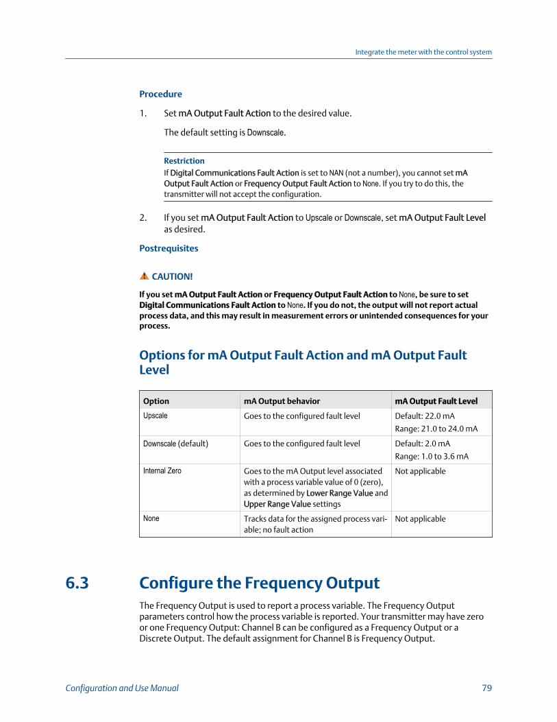
Procedure
1. Set mA Output Fault Action to the desired value.
The default setting is Downscale.
RestrictionIf Digital Communications Fault Action is set to NAN (not a number), you cannot set mAOutput Fault Action or Frequency Output Fault Action to None. If you try to do this, thetransmitter will not accept the configuration.
2. If you set mA Output Fault Action to Upscale or Downscale, set mA Output Fault Levelas desired.
Postrequisites
CAUTION!
If you set mA Output Fault Action or Frequency Output Fault Action to None, be sure to setDigital Communications Fault Action to None. If you do not, the output will not report actualprocess data, and this may result in measurement errors or unintended consequences for yourprocess.
Options for mA Output Fault Action and mA Output FaultLevel
Option mA Output behavior mA Output Fault Level
Upscale Goes to the configured fault level Default: 22.0 mA
Range: 21.0 to 24.0 mA
Downscale (default) Goes to the configured fault level Default: 2.0 mA
Range: 1.0 to 3.6 mA
Internal Zero Goes to the mA Output level associatedwith a process variable value of 0 (zero),as determined by Lower Range Value andUpper Range Value settings
Not applicable
None Tracks data for the assigned process vari-able; no fault action
Not applicable
6.3 Configure the Frequency OutputThe Frequency Output is used to report a process variable. The Frequency Outputparameters control how the process variable is reported. Your transmitter may have zeroor one Frequency Output: Channel B can be configured as a Frequency Output or aDiscrete Output. The default assignment for Channel B is Frequency Output.
Integrate the meter with the control system
Configuration and Use Manual 79

RestrictionThe process variable assigned to the primary mA Output is automatically assigned to the FrequencyOutput. You cannot assign a different process variable.
ImportantWhenever you change a Frequency Output parameter, verify all other Frequency Output parametersbefore returning the flowmeter to service. In some situations, the transmitter automatically loads aset of stored values, and these values may not be appropriate for your application.
6.3.1 Configure Frequency Output Polarity
Display OFF-LINE MAINT > OFF-LINE CONFG > IO > CH B > SET FO > FO POLAR
ProLink III Device Tools > Configuration > I/O > Outputs > Frequency Output
Field Communicator Configure > Manual Setup > Inputs/Outputs > Frequency Output > FO Settings > FO Po-
larity
Overview
Frequency Output Polarity controls how the output indicates the ON (active) state. Thedefault value, Active High, is appropriate for most applications. Your receiving device mightrequire an Active Low setting.
Procedure
Set Frequency Output Polarity as desired.
The default setting is Active High.
Options for Frequency Output Polarity
Polarity option Reference voltage (OFF) Pulse voltage (ON)
Active High 0 As determined by power supply,pull-up resistor, and load. Seethe installation manual for yourtransmitter.
Active Low As determined by power supply,pull-up resistor, and load. Seethe installation manual for yourtransmitter.
0
Integrate the meter with the control system
80 Micro Motion Model 1700 Transmitters with Analog Outputs
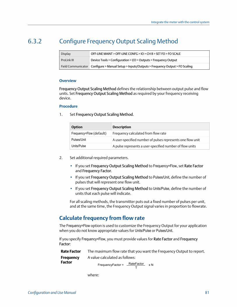
6.3.2 Configure Frequency Output Scaling Method
Display OFF-LINE MAINT > OFF-LINE CONFG > IO > CH B > SET FO > FO SCALE
ProLink III Device Tools > Configuration > I/O > Outputs > Frequency Output
Field Communicator Configure > Manual Setup > Inputs/Outputs > Frequency Output > FO Scaling
Overview
Frequency Output Scaling Method defines the relationship between output pulse and flowunits. Set Frequency Output Scaling Method as required by your frequency receivingdevice.
Procedure
1. Set Frequency Output Scaling Method.
Option Description
Frequency=Flow (default) Frequency calculated from flow rate
Pulses/Unit A user-specified number of pulses represents one flow unit
Units/Pulse A pulse represents a user-specified number of flow units
2. Set additional required parameters.
• If you set Frequency Output Scaling Method to Frequency=Flow, set Rate Factorand Frequency Factor.
• If you set Frequency Output Scaling Method to Pulses/Unit, define the number ofpulses that will represent one flow unit.
• If you set Frequency Output Scaling Method to Units/Pulse, define the number ofunits that each pulse will indicate.
For all scaling methods, the transmitter puts out a fixed number of pulses per unit,and at the same time, the Frequency Output signal varies in proportion to flowrate.
Calculate frequency from flow rateThe Frequency=Flow option is used to customize the Frequency Output for your applicationwhen you do not know appropriate values for Units/Pulse or Pulses/Unit.
If you specify Frequency=Flow, you must provide values for Rate Factor and FrequencyFactor:
Rate Factor The maximum flow rate that you want the Frequency Output to report.
FrequencyFactor
A value calculated as follows:
FrequencyFactor = x NRateFactorT
where:
Integrate the meter with the control system
Configuration and Use Manual 81

T Factor to convert selected time base to seconds
N Number of pulses per flow unit, as configured in the receivingdevice
The resulting Frequency Factor must be within the range of the Frequency Output (0 to10,000 Hz :
• If Frequency Factor is less than1 Hz, reconfigure the receiving device for a higherpulses/unit setting.
• If Frequency Factor is greater than 10,000 Hz, reconfigure the receiving device for alower pulses/unit setting.
6.3.3 Configure Frequency Output Fault Action and FrequencyOutput Fault Level
Display Not available
ProLink III Device Tools > Configuration > Fault Processing
Field Communicator • Configure > Manual Setup > Inputs/Outputs > Frequency Output > FO Fault Parame-
ters > FO Fault Action
• Configure > Manual Setup > Inputs/Outputs > Frequency Output > FO Fault Parame-
ters > FO Fault Level
Overview
Frequency Output Fault Action controls the behavior of the Frequency Output if thetransmitter encounters an internal fault condition.
NoteFor some faults only: If Fault Timeout is set to a non-zero value, the transmitter will not implementthe fault action until the timeout has elapsed.
Procedure
1. Set Frequency Output Fault Action as desired.
The default value is Downscale (0 Hz).
2. If you set Frequency Output Fault Action to Upscale, set Frequency Fault Level to thedesired value.
The default value is 15000 Hz. The range is 10 to 15000 Hz.
Integrate the meter with the control system
82 Micro Motion Model 1700 Transmitters with Analog Outputs
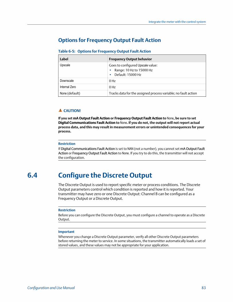
Options for Frequency Output Fault Action
Options for Frequency Output Fault Action Table 6-5:
Label Frequency Output behavior
Upscale Goes to configured Upscale value:• Range: 10 Hz to 15000 Hz• Default: 15000 Hz
Downscale 0 Hz
Internal Zero 0 Hz
None (default) Tracks data for the assigned process variable; no fault action
CAUTION!
If you set mA Output Fault Action or Frequency Output Fault Action to None, be sure to setDigital Communications Fault Action to None. If you do not, the output will not report actualprocess data, and this may result in measurement errors or unintended consequences for yourprocess.
RestrictionIf Digital Communications Fault Action is set to NAN (not a number), you cannot set mA Output FaultAction or Frequency Output Fault Action to None. If you try to do this, the transmitter will not acceptthe configuration.
6.4 Configure the Discrete OutputThe Discrete Output is used to report specific meter or process conditions. The DiscreteOutput parameters control which condition is reported and how it is reported. Yourtransmitter may have zero or one Discrete Output: Channel B can be configured as aFrequency Output or a Discrete Output.
RestrictionBefore you can configure the Discrete Output, you must configure a channel to operate as a DiscreteOutput.
ImportantWhenever you change a Discrete Output parameter, verify all other Discrete Output parametersbefore returning the meter to service. In some situations, the transmitter automatically loads a set ofstored values, and these values may not be appropriate for your application.
Integrate the meter with the control system
Configuration and Use Manual 83
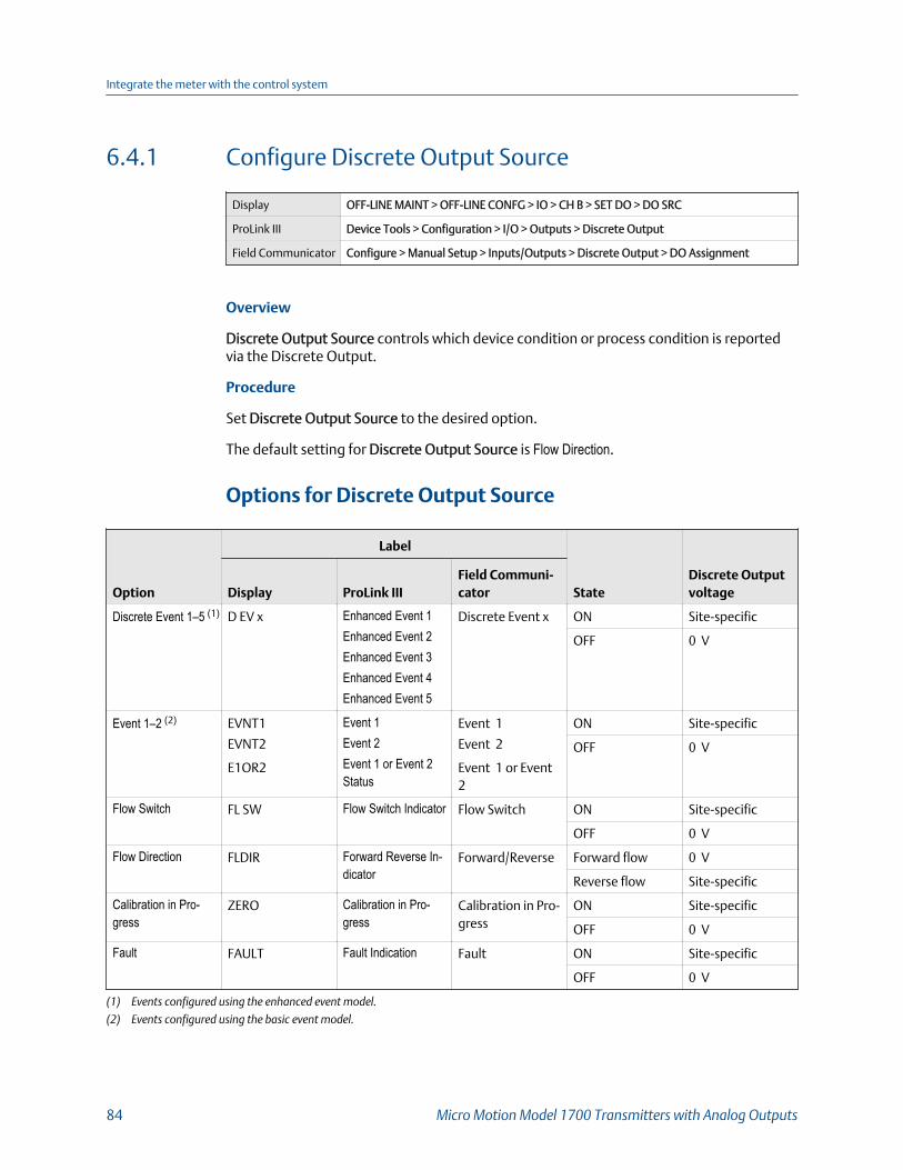
6.4.1 Configure Discrete Output Source
Display OFF-LINE MAINT > OFF-LINE CONFG > IO > CH B > SET DO > DO SRC
ProLink III Device Tools > Configuration > I/O > Outputs > Discrete Output
Field Communicator Configure > Manual Setup > Inputs/Outputs > Discrete Output > DO Assignment
Overview
Discrete Output Source controls which device condition or process condition is reportedvia the Discrete Output.
Procedure
Set Discrete Output Source to the desired option.
The default setting for Discrete Output Source is Flow Direction.
Options for Discrete Output Source
Option
Label
StateDiscrete OutputvoltageDisplay ProLink III
Field Communi-cator
Discrete Event 1–5 (1) D EV x Enhanced Event 1Enhanced Event 2Enhanced Event 3Enhanced Event 4Enhanced Event 5
Discrete Event x ON Site-specific
OFF 0 V
Event 1–2 (2) EVNT1
EVNT2
E1OR2
Event 1Event 2Event 1 or Event 2Status
Event 1
Event 2
Event 1 or Event 2
ON Site-specific
OFF 0 V
Flow Switch FL SW Flow Switch Indicator Flow Switch ON Site-specific
OFF 0 V
Flow Direction FLDIR Forward Reverse In-dicator
Forward/Reverse Forward flow 0 V
Reverse flow Site-specific
Calibration in Pro-gress
ZERO Calibration in Pro-gress
Calibration in Pro-gress
ON Site-specific
OFF 0 V
Fault FAULT Fault Indication Fault ON Site-specific
OFF 0 V
(1) Events configured using the enhanced event model.
(2) Events configured using the basic event model.
Integrate the meter with the control system
84 Micro Motion Model 1700 Transmitters with Analog Outputs

ImportantIf you assign Flow Switch to the Discrete Output, you should also configure Flow Switch Variable, FlowSwitch Setpoint, and Hysteresis.
Related information
Configure an enhanced eventFault indication with the Discrete Output
Configure Flow Switch parameters
Display OFF-LINE MAINT > OFF-LINE CONFG > IO > CH B > SET DO > CONFIG FL SW
ProLink III Device Tools > Configuration > I/O > Outputs > Discrete Output
Field Communicator • Configure > Manual Setup > Inputs/Outputs > Discrete Output > Flow Switch Source
• Configure > Manual Setup > Inputs/Outputs > Discrete Output > Flow Switch Set-
point
• Configure > Manual Setup > Inputs/Outputs > Discrete Output > Hysteresis
Overview
Flow Switch is used to indicate that the flow rate (measured by the configured flow variable)has moved past the configured setpoint, in either direction. The flow switch isimplemented with a user-configurable hysteresis.
Procedure
1. Set Discrete Output Source to Flow Switch, if you have not already done so.
2. Set Flow Switch Variable to the flow variable that you want to use to control the flowswitch.
3. Set Flow Switch Setpoint to the value at which the flow switch will be triggered(after Hysteresis is applied).
• If the flow rate is below this value, the Discrete Output is ON.
• If the flow rate is above this value, the Discrete Output is OFF.
4. Set Hysteresis to the percentage of variation above and below the setpoint that willoperate as a deadband.
Hysteresis defines a range around the setpoint within which the flow switch will notchange. The default is 5%. The valid range is 0.1% to 10%.
Example: If Flow Switch Setpoint = 100 g/sec and Hysteresis = 5%, and the firstmeasured flow rate is above 100 g/sec, the Discrete Output is OFF. It will remain OFFunless the flow rate drops below 95 g/sec. If this happens, the Discrete Output willturn ON, and remain ON until the flow rate rises above 105 g/sec. At this point itturns OFF and will remain OFF until the flow rate drops below 95 g/sec.
Integrate the meter with the control system
Configuration and Use Manual 85
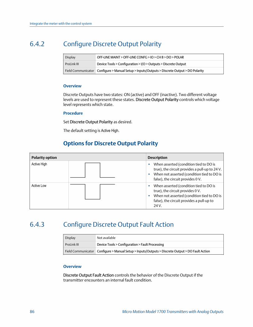
6.4.2 Configure Discrete Output Polarity
Display OFF-LINE MAINT > OFF-LINE CONFG > IO > CH B > DO > POLAR
ProLink III Device Tools > Configuration > I/O > Outputs > Discrete Output
Field Communicator Configure > Manual Setup > Inputs/Outputs > Discrete Output > DO Polarity
Overview
Discrete Outputs have two states: ON (active) and OFF (inactive). Two different voltagelevels are used to represent these states. Discrete Output Polarity controls which voltagelevel represents which state.
Procedure
Set Discrete Output Polarity as desired.
The default setting is Active High.
Options for Discrete Output Polarity
Polarity option Description
Active High • When asserted (condition tied to DO istrue), the circuit provides a pull-up to 24 V.
• When not asserted (condition tied to DO isfalse), the circuit provides 0 V.
Active Low • When asserted (condition tied to DO istrue), the circuit provides 0 V.
• When not asserted (condition tied to DO isfalse), the circuit provides a pull-up to24 V.
6.4.3 Configure Discrete Output Fault Action
Display Not available
ProLink III Device Tools > Configuration > Fault Processing
Field Communicator Configure > Manual Setup > Inputs/Outputs > Discrete Output > DO Fault Action
Overview
Discrete Output Fault Action controls the behavior of the Discrete Output if thetransmitter encounters an internal fault condition.
Integrate the meter with the control system
86 Micro Motion Model 1700 Transmitters with Analog Outputs
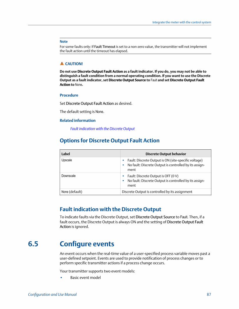
NoteFor some faults only: If Fault Timeout is set to a non-zero value, the transmitter will not implementthe fault action until the timeout has elapsed.
CAUTION!
Do not use Discrete Output Fault Action as a fault indicator. If you do, you may not be able todistinguish a fault condition from a normal operating condition. If you want to use the DiscreteOutput as a fault indicator, set Discrete Output Source to Fault and set Discrete Output FaultAction to None.
Procedure
Set Discrete Output Fault Action as desired.
The default setting is None.
Related information
Fault indication with the Discrete Output
Options for Discrete Output Fault Action
Label Discrete Output behavior
Upscale • Fault: Discrete Output is ON (site-specific voltage)• No fault: Discrete Output is controlled by its assign-
ment
Downscale • Fault: Discrete Output is OFF (0 V)• No fault: Discrete Output is controlled by its assign-
ment
None (default) Discrete Output is controlled by its assignment
Fault indication with the Discrete OutputTo indicate faults via the Discrete Output, set Discrete Output Source to Fault. Then, if afault occurs, the Discrete Output is always ON and the setting of Discrete Output FaultAction is ignored.
6.5 Configure eventsAn event occurs when the real-time value of a user-specified process variable moves past auser-defined setpoint. Events are used to provide notification of process changes or toperform specific transmitter actions if a process change occurs.
Your transmitter supports two event models:
• Basic event model
Integrate the meter with the control system
Configuration and Use Manual 87

• Enhanced event model
6.5.1 Configure a basic event
Display Not available
ProLink III Device Tools > Configuration > Events > Basic Events
Field Communicator Not available
Overview
A basic event is used to provide notification of process changes. A basic event occurs (isON) if the real-time value of a user-specified process variable moves above (HI) or below(LO) a user-defined setpoint. You can define up to two basic events. Event status can bequeried via digital communications, and a Discrete Output can be configured to reportevent status.
Procedure
1. Select the event that you want to configure.
2. Specify Event Type.
Option Description
HI x > A
The event occurs when the value of the assigned process variable (x) isgreater than the setpoint (Setpoint A), endpoint not included.
LO x < A
The event occurs when the value of the assigned process variable (x) isless than the setpoint (Setpoint A), endpoint not included.
3. Assign a process variable to the event.
4. Set a value for Setpoint A.
5. (Optional) Configure a Discrete Output to switch states in response to the eventstatus.
6.5.2 Configure an enhanced event
Display Not available
ProLink III Device Tools > Configuration > Events > Enhanced Events
Field Communicator Configure > Alert Setup > Discrete Events
Integrate the meter with the control system
88 Micro Motion Model 1700 Transmitters with Analog Outputs

Overview
An enhanced event is used to provide notification of process changes and, optionally, toperform specific transmitter actions if the event occurs. An enhanced event occurs (is ON)if the real-time value of a user-specified process variable moves above (HI) or below (LO) auser-defined setpoint, or in range (IN) or out of range (OUT) with respect to two user-defined setpoints. You can define up to five enhanced events.
Procedure
1. Select the event that you want to configure.
2. Specify Event Type.
Option Description
HI x > A
The event occurs when the value of the assigned process variable (x) isgreater than the setpoint (Setpoint A), endpoint not included.
LO x < A
The event occurs when the value of the assigned process variable (x) isless than the setpoint (Setpoint A), endpoint not included.
IN A ≤ x ≤ B
The event occurs when the value of the assigned process variable (x) is inrange, that is, between Setpoint A and Setpoint B, endpoints included.
OUT x ≤ A or x ≥ B
The event occurs when the value of the assigned process variable (x) isout of range, that is, less than Setpoint A or greater than Setpoint B, end-points included.
3. Assign a process variable to the event.
4. Set values for the required setpoints.
• For HI and LO events, set Setpoint A.
• For IN and OUT events, set Setpoint A and Setpoint B.
5. (Optional) Configure a Discrete Output to switch states in response to the eventstatus.
6. (Optional) Specify the action or actions that the transmitter will perform when theevent occurs.
• With the display: OFF-LINE MAINT > OFF-LINE CONFG > IO > CH C > SET DI > DIACT
• With ProLink III: Device Tools > Configuration > I/O > Action Assignment
• With the Field Communicator: Configure > Alert Setup > Discrete Events > AssignDiscrete Action
Integrate the meter with the control system
Configuration and Use Manual 89
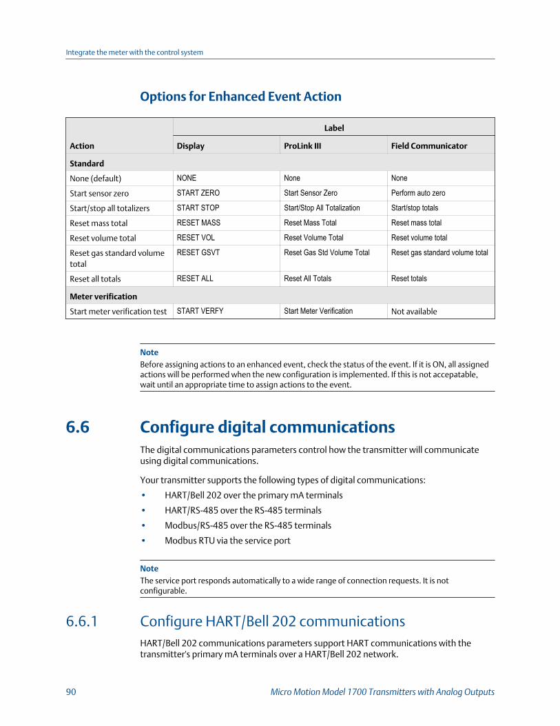
Options for Enhanced Event Action
Action
Label
Display ProLink III Field Communicator
Standard
None (default) NONE None None
Start sensor zero START ZERO Start Sensor Zero Perform auto zero
Start/stop all totalizers START STOP Start/Stop All Totalization Start/stop totals
Reset mass total RESET MASS Reset Mass Total Reset mass total
Reset volume total RESET VOL Reset Volume Total Reset volume total
Reset gas standard volumetotal
RESET GSVT Reset Gas Std Volume Total Reset gas standard volume total
Reset all totals RESET ALL Reset All Totals Reset totals
Meter verification
Start meter verification test START VERFY Start Meter Verification Not available
NoteBefore assigning actions to an enhanced event, check the status of the event. If it is ON, all assignedactions will be performed when the new configuration is implemented. If this is not accepatable,wait until an appropriate time to assign actions to the event.
6.6 Configure digital communicationsThe digital communications parameters control how the transmitter will communicateusing digital communications.
Your transmitter supports the following types of digital communications:
• HART/Bell 202 over the primary mA terminals
• HART/RS-485 over the RS-485 terminals
• Modbus/RS-485 over the RS-485 terminals
• Modbus RTU via the service port
NoteThe service port responds automatically to a wide range of connection requests. It is notconfigurable.
6.6.1 Configure HART/Bell 202 communicationsHART/Bell 202 communications parameters support HART communications with thetransmitter's primary mA terminals over a HART/Bell 202 network.
Integrate the meter with the control system
90 Micro Motion Model 1700 Transmitters with Analog Outputs

Configure basic HART parameters
Display OFF-LINE MAINT > OFF-LINE CONFG > COMM
ProLink III Device Tools > Configuration > Communications > Communications (HART)
Field Communicator Configure > Manual Setup > Inputs/Outputs > Communications > HART Communica-
tions
Overview
Basic HART parameters include the HART address, HART tags, and the operation of theprimary mA Output.
HART/Bell 202 communications parameters support HART communication with thetransmitter's primary mA terminals over a HART/Bell 202 network. The HART/Bell 202communications parameters include:
• HART Address (Polling Address)
• mA Output Action
• Burst Parameters (optional)
• HART Variables (optional)
Procedure
1. Set HART Address to a value that is unique on your network.
• Default: 0
• Range: 0 to 15
Tips
• The default address is typically used unless you are in a multidrop environment.
• Devices using HART protocol to communicate with the transmitter may use either HARTAddress or HART Tag (Software Tag) to identify the transmitter. Configure either or both,as required by your other HART devices.
2. Ensure that mA Output Action is configured appropriately.
Option Description
Enabled (Live) The primary mA Output reports process data as configured.
Disabled (Fixed) The primary mA Output is fixed at 4 mA and does not report processdata.
Integrate the meter with the control system
Configuration and Use Manual 91
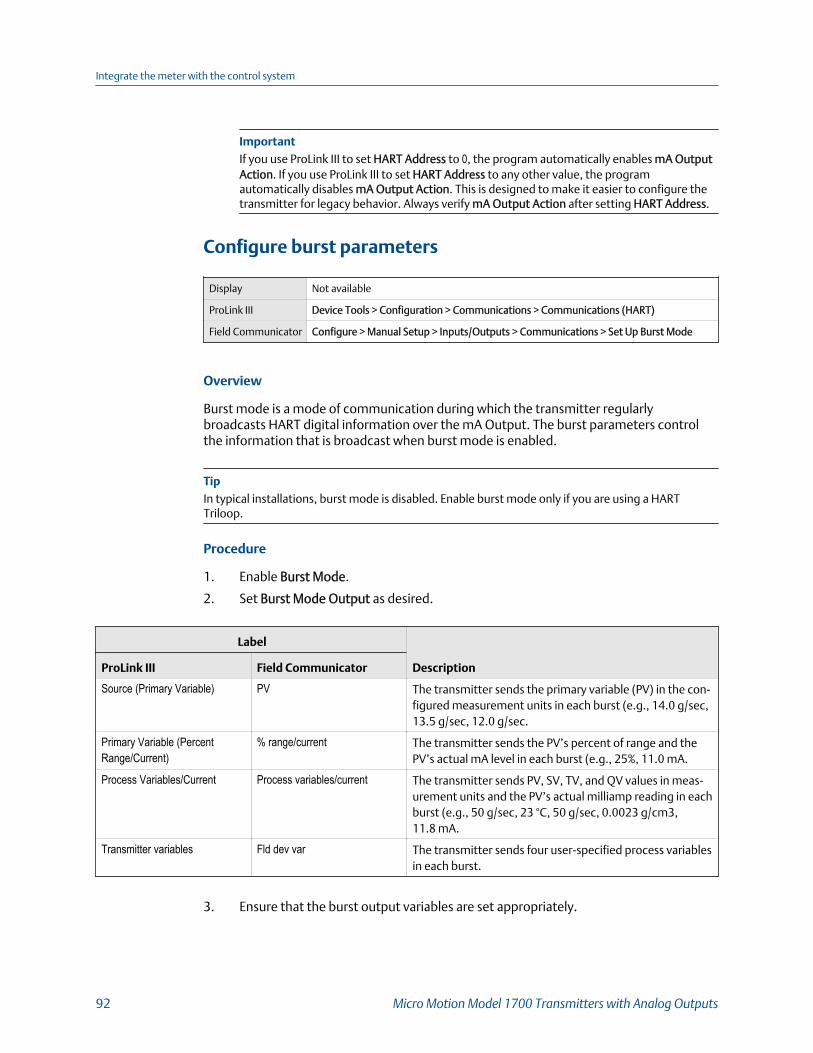
ImportantIf you use ProLink III to set HART Address to 0, the program automatically enables mA OutputAction. If you use ProLink III to set HART Address to any other value, the programautomatically disables mA Output Action. This is designed to make it easier to configure thetransmitter for legacy behavior. Always verify mA Output Action after setting HART Address.
Configure burst parameters
Display Not available
ProLink III Device Tools > Configuration > Communications > Communications (HART)
Field Communicator Configure > Manual Setup > Inputs/Outputs > Communications > Set Up Burst Mode
Overview
Burst mode is a mode of communication during which the transmitter regularlybroadcasts HART digital information over the mA Output. The burst parameters controlthe information that is broadcast when burst mode is enabled.
TipIn typical installations, burst mode is disabled. Enable burst mode only if you are using a HARTTriloop.
Procedure
1. Enable Burst Mode.
2. Set Burst Mode Output as desired.
Label
DescriptionProLink III Field Communicator
Source (Primary Variable) PV The transmitter sends the primary variable (PV) in the con-figured measurement units in each burst (e.g., 14.0 g/sec,13.5 g/sec, 12.0 g/sec.
Primary Variable (PercentRange/Current)
% range/current The transmitter sends the PV’s percent of range and thePV’s actual mA level in each burst (e.g., 25%, 11.0 mA.
Process Variables/Current Process variables/current The transmitter sends PV, SV, TV, and QV values in meas-urement units and the PV’s actual milliamp reading in eachburst (e.g., 50 g/sec, 23 °C, 50 g/sec, 0.0023 g/cm3,11.8 mA.
Transmitter variables Fld dev var The transmitter sends four user-specified process variablesin each burst.
3. Ensure that the burst output variables are set appropriately.
Integrate the meter with the control system
92 Micro Motion Model 1700 Transmitters with Analog Outputs

• If you set Burst Mode Output to send four user-specified variables, set the fourprocess variables to be sent in each burst.
• If you set Burst Mode Output to any other option, ensure that the HART variablesare set as desired.
Configure HART variables (PV, SV, TV, QV)
Display Not available
ProLink III Device Tools > Configuration > Communications > Communications (HART)
Field Communicator Configure > Manual Setup > Inputs/Outputs > Variable Mapping
Overview
The HART variables are a set of four variables predefined for HART use. The HART variablesinclude the Primary Variable (PV), Secondary Variable (SV), Tertiary Variable (TV), andQuaternary Variable (QV). You can assign specific process variables to the HART variables,and then use standard HART methods to read or broadcast the assigned process data.
RestrictionThe TV is automatically set to match the PV and cannot be configured independently.
TipThe Tertiary Variable and Quaternary Variable are also called the Third Variable (TV) and FourthVariable (FV).
Options for HART variables
Standard HART process variablesTable 6-6:
Process variable Primary Varia-ble (PV)
SecondaryVariable (SV)
Third Variable(TV)
Fourth Varia-ble (QV )
Gas Standard Volume Flow Rate
Gas Standard Volume Inventory
Gas Standard Volume Total
Line (Gross) Volume Flow Rate
Line (Gross) Volume Inventory
Line (Gross) Volume Total
Mass Flow Rate
Mass Inventory
Mass Total
Integrate the meter with the control system
Configuration and Use Manual 93

PVR-only HART process variablesTable 6-7:
Process variable Primary Varia-ble (PV)
SecondaryVariable (SV)
Third Variable(TV)
Fourth Varia-ble (QV )
Corrected Oil Flow
Corrected Oil Total
Corrected Water Cut
Corrected Water Flow
Corrected Water Total
Density of Oil @ Line Fixd degAPI
Density of Oil @ Line Fixd SGU
Oil Total @ Line
Shrinkage Factor Corrected Oil Flow @ 60F
Shrinkage Factor Corrected Oil Flow @ Line
Shrinkage Factor Corrected Oil Total @ 60F
Shrinkage Factor Corrected Oil Total @ Line
Shrinkage Factor Corrected Total of Mix @ 60F
Shrinkage Factor Corrected Volume Of Mix @ 60F
Uncorrected Oil Flow
Uncorrected Water Cut
Uncorrected Water Flow
Volume Flow of Mix at Line
Volume Total Of Mix @ Line
Water Total @ Line
TMR-only HART process variablesTable 6-8:
Process variable Primary Varia-ble (PV)
SecondaryVariable (SV)
Third Variable(TV)
Fourth Varia-ble (QV )
Remediated Mass Flow
Remediated Mass Total
Remediated Mass Inventory
PVR- and TBR-only HART process variablesTable 6-9:
Process variable Primary Varia-ble (PV)
SecondaryVariable (SV)
Third Variable(TV)
Fourth Varia-ble (QV )
Unremediated Density
Integrate the meter with the control system
94 Micro Motion Model 1700 Transmitters with Analog Outputs
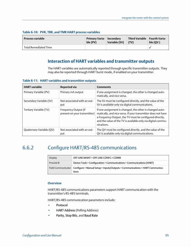
PVR, TBR, and TMR HART process variablesTable 6-10:
Process variable Primary Varia-ble (PV)
SecondaryVariable (SV)
Third Variable(TV)
Fourth Varia-ble (QV )
Total Remediated Time
Interaction of HART variables and transmitter outputs
The HART variables are automatically reported through specific transmitter outputs. Theymay also be reported through HART burst mode, if enabled on your transmitter.
HART variables and transmitter outputsTable 6-11:
HART variable Reported via Comments
Primary Variable (PV) Primary mA output If one assignment is changed, the other is changed auto-matically, and vice versa.
Secondary Variable (SV) Not associated with an out-put
The SV must be configured directly, and the value of theSV is available only via digital communications.
Tertiary Variable (TV) Frequency Output (ifpresent on your transmitter)
If one assignment is changed, the other is changed auto-matically, and vice versa. If your transmitter does not havea Frequency Output, the TV must be configured directly,and the value of the TV is available only via digital commu-nications.
Quaternary Variable (QV) Not associated with an out-put
The QV must be configured directly, and the value of theQV is available only via digital communications.
6.6.2 Configure HART/RS-485 communications
Display OFF-LINE MAINT > OFF-LINE CONFG > COMM
ProLink III Device Tools > Configuration > Communications > Communications (HART)
Field Communicator Configure > Manual Setup > Inputs/Outputs > Communications > HART Communica-
tions
Overview
HART/RS-485 communications parameters support HART communication with thetransmitter's RS-485 terminals.
HART/RS-485 communication parameters include:
• Protocol
• HART Address (Polling Address)
• Parity, Stop Bits, and Baud Rate
Integrate the meter with the control system
Configuration and Use Manual 95

RestrictionThe transmitter uses the same RS-485 terminals for HART/RS-485, Modbus RTU, and Modbus ASCIIcommunications. All RS-485 connection requests must use the same protocol and connectionparameters that are configured in the transmitter.
Procedure
1. Set Protocol to HART RS-485.
2. Set Baud Rate to match the baud rate that will be used by your HART master.
3. Set Parity to match the parity that will be used by your HART master.
4. Set Stop Bits to match the stop bits setting that will be used by your HART master.
5. Set HART Address to a unique value on your network.
Valid address values are between 0 and 15. The default address (0) is typically usedunless you are in a multidrop environment.
TipDevices using HART protocol to communicate with the transmitter may use either HARTAddress or HART Tag (Software Tag) to identify the transmitter. Configure either or both, asrequired by your other HART devices.
6.6.3 Configure Modbus/RS-485 communications
Display OFF-LINE MAINT > OFF-LINE CONFG > COMM
ProLink III Device Tools > Configuration > Communications > RS-485 Terminals
Field Communicator Configure > Manual Setup > Inputs/Outputs > Communications > Set Up RS-485 Port
Overview
Modbus/RS-485 communications parameters control Modbus communication with thetransmitter's RS-485 terminals.
Procedure
1. Set Disable Modbus ASCII as desired.
Support for Modbus ASCII limits the set of addresses that are available for thetransmitter's Modbus address.
Modbus ASCII support Available Modbus addresses
Disabled 1–127, excluding 111 (111 is reserved to the service port)
Enabled 1–15, 32–47, 64–79, and 96–110
2. Set Protocol to match the protocol used by your Modbus/RS-485 host.
Integrate the meter with the control system
96 Micro Motion Model 1700 Transmitters with Analog Outputs

Option Description
Modbus RTU (default) 8–bit communications
Modbus ASCII 7–bit communications
If support for Modbus ASCII is disabled, you must use Modbus RTU.
3. Set Modbus Address to a unique value on the network.
4. Set Parity, Stop Bits, and Baud Rate as appropriate for your network.
5. Set Floating-Point Byte Order to match the byte order used by your Modbus host.
Code Byte order
0 1–2 3–4
1 3–4 1–2
2 2–1 4–3
3 4–3 2–1
See the following table for the bit structure of bytes 1 through 7.
Bit structure of floating-point bytesTable 6-12:
Byte Bits Definition
1 SEEEEEEE S=Sign
E=Exponent
2 EMMMMMMM E=Exponent
M=Mantissa
3 MMMMMMMM M=Mantissa
4 MMMMMMMM M=Mantissa
6. (Optional) Set Additional Communications Response Delay in delay units.
A delay unit is 2/3 of the time required to transmit one character, as calculated forthe port currently in use and the character transmission parameters. Valid valuesrange from 1 to 255.
Additional Communications Response Delay is used to synchronize Modbuscommunications with hosts that operate at a slower speed than the transmitter. Thevalue specified here will be added to each response the transmitter sends to thehost.
TipDo not set Additional Communications Response Delay unless required by your Modbus host.
Integrate the meter with the control system
Configuration and Use Manual 97

6.6.4 Configure Digital Communications Fault Action
Display Not available
ProLink III Device Tools > Configuration > Fault Processing
Field Communicator Configure > Alert Setup > I/O Fault Actions > Comm Fault Action
Overview
Digital Communications Fault Actionspecifies the values that will be reported via digitalcommunications if the device encounters an internal fault condition.
Procedure
Set Digital Communications Fault Action as desired.
The default setting is None.
Restrictions
• If mA Output Fault Action or Frequency Output Fault Action is set to None, DigitalCommunications Fault Action should also be set to None. If you do not, the output will not reportactual process data, and this may result in measurement errors or unintended consequences foryour process.
• If you set Digital Communications Fault Action to NAN, you cannot set mA Output Fault Action orFrequency Output Fault Action to None. If you try to do this, the transmitter will not accept theconfiguration.
Options for Digital Communications Fault Action
Label
DescriptionProLink III Field Communicator
Upscale Upscale • Process variable values indicate that the val-ue is greater than the upper sensor limit.
• Totalizers stop incrementing.
Downscale Downscale • Process variable values indicate that the val-ue is lower than the lower sensor limit.
• Totalizers stop incrementing.
Zero IntZero-All 0 • Flow rate variables go to the value that rep-resents a flow rate of 0 (zero).
• Density is reported as 0.
• Temperature is reported as 0 °C , or the
equivalent if other units are used (e.g.,32 °F .
• Drive gain is reported as measured.• Totalizers stop incrementing.
Integrate the meter with the control system
98 Micro Motion Model 1700 Transmitters with Analog Outputs

Label
DescriptionProLink III Field Communicator
Not a Number Not-a-Number • Process variables are reported as IEEENAN.
• Drive gain is reported as measured.• Modbus scaled integers are reported as Max
Int.
• Totalizers stop incrementing.
Flow to Zero IntZero-Flow 0 • Flow rates are reported as 0.
• Other process variables are reported asmeasured.
• Totalizers stop incrementing.
None None (default) • All process variables are reported as meas-ured.
• Totalizers increment if they are running.
CAUTION!
If you set mA Output Fault Action or Frequency Output Fault Action to None, be sure to setDigital Communications Fault Action to None. If you do not, the output will not report actualprocess data, and this may result in measurement errors or unintended consequences for yourprocess.
RestrictionIf Digital Communications Fault Action is set to NAN (not a number), you cannot set mA Output FaultAction or Frequency Output Fault Action to None. If you try to do this, the transmitter will not acceptthe configuration.
Integrate the meter with the control system
Configuration and Use Manual 99

Integrate the meter with the control system
100 Micro Motion Model 1700 Transmitters with Analog Outputs

7 Complete the configurationTopics covered in this chapter:
• Test or tune the system using sensor simulation
• Back up transmitter configuration
• Enable write‐protection on the transmitter configuration
7.1 Test or tune the system using sensorsimulationUse sensor simulation to test the system's response to a variety of process conditions,including boundary conditions, problem conditions, or alert conditions, or to tune theloop.
RestrictionSensor simulation is available only on flowmeters with the enhanced core processor.
Prerequisites
Before enabling sensor simulation, ensure that your process can tolerate the effects of thesimulated process values.
Procedure
1. Navigate to the sensor simulation menu.
Communications tool Menu path
Display Not available
ProLink III Device Tools > Diagnostics > Testing > Sensor Simulation
Field Communicator Service Tools > Simulate > Simulate Sensor
2. Enable sensor simulation.
3. For mass flow, set Wave Form as desired and enter the required values.
Option Required values
Fixed Fixed Value
Sawtooth Period
Minimum
Maximum
Complete the configuration
Configuration and Use Manual 101
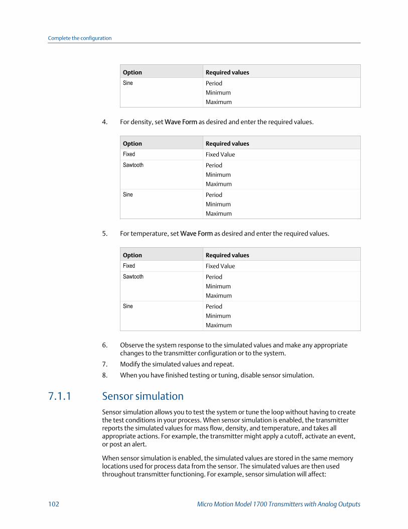
Option Required values
Sine Period
Minimum
Maximum
4. For density, set Wave Form as desired and enter the required values.
Option Required values
Fixed Fixed Value
Sawtooth Period
Minimum
Maximum
Sine Period
Minimum
Maximum
5. For temperature, set Wave Form as desired and enter the required values.
Option Required values
Fixed Fixed Value
Sawtooth Period
Minimum
Maximum
Sine Period
Minimum
Maximum
6. Observe the system response to the simulated values and make any appropriatechanges to the transmitter configuration or to the system.
7. Modify the simulated values and repeat.
8. When you have finished testing or tuning, disable sensor simulation.
7.1.1 Sensor simulationSensor simulation allows you to test the system or tune the loop without having to createthe test conditions in your process. When sensor simulation is enabled, the transmitterreports the simulated values for mass flow, density, and temperature, and takes allappropriate actions. For example, the transmitter might apply a cutoff, activate an event,or post an alert.
When sensor simulation is enabled, the simulated values are stored in the same memorylocations used for process data from the sensor. The simulated values are then usedthroughout transmitter functioning. For example, sensor simulation will affect:
Complete the configuration
102 Micro Motion Model 1700 Transmitters with Analog Outputs

• All mass flow rate, temperature, and density values displayed or reported viaoutputs or digital communications
• The mass total and mass inventory values
• All volume calculations and data, including reported values, volume totals, andvolume inventories
• All mass, temperature, density, or volume values logged to Data Logger
Sensor simulation does not affect any diagnostic values.
Unlike actual mass flow rate and density values, the simulated values are not temperature-compensated (adjusted for the effect of temperature on the sensor’s flow tubes).
7.2 Back up transmitter configurationProLink III provides a configuration upload/download function which allows you to saveconfiguration sets to your PC. This allows you to back up and restore your transmitterconfiguration. This is also a convenient way to replicate a configuration across multipledevices.
RestrictionThis function is not available with any other communications tools.
Procedure
To back up the transmitter configuration using ProLink III:
1. Choose Device Tools > Configuration Transfer > Save or Load Configuration Data.
2. In the Configuration groupbox, select the configuration data you want to save.
3. Click Save, then specify a file name and location on your computer.
4. Click Start Save.
The backup file is saved to the specified name and location. It is saved as a text file and canbe read using any text editor.
7.3 Enable write-protection on the transmitterconfiguration
Display OFF-LINE MAINT > CONFIG > LOCK
ProLink III Device Tools > Configuration > Write-Protection
Field Communicator Configure > Manual Setup > Info Parameters > Transmitter Info > Write Protect
Complete the configuration
Configuration and Use Manual 103

Overview
If the transmitter is write-protected, the configuration is locked and nobody can change ituntil it is unlocked. This prevents accidental or unauthorized changes to the transmitterconfiguration parameters.
Complete the configuration
104 Micro Motion Model 1700 Transmitters with Analog Outputs
Part IIIOperations, maintenance, andtroubleshooting
Chapters covered in this part:
• Transmitter operation
• Measurement support
• Troubleshooting
Operations, maintenance, and troubleshooting
Configuration and Use Manual 105

Operations, maintenance, and troubleshooting
106 Micro Motion Model 1700 Transmitters with Analog Outputs

8 Transmitter operationTopics covered in this chapter:
• Record the process variables
• View process variables
• View transmitter status using the status LED
• View and acknowledge status alerts
• Read totalizer and inventory values
• Start and stop totalizers and inventories
• Reset totalizers
• Reset inventories
8.1 Record the process variablesMicro Motion suggests that you make a record of specific process variable measurements,including the acceptable range of measurements, under normal operating conditions. Thisdata will help you recognize when the process or diagnostic variables are unusually high orlow, and may help you diagnose and troubleshoot application issues.
Procedure
Record the following process and diagnostic variables, under normal operating conditions.
Variable
Measurement
Typical average Typical high Typical low
Flow rate
Density
Temperature
Tube frequency
Pickoff voltage
Drive gain
Transmitter operation
Configuration and Use Manual 107

8.2 View process variables
Display Scroll to the desired process variable. If AutoScroll is enabled, you can wait until the
process variable is displayed. See Section 8.2.1 for more information.
ProLink III View the desired variable on the main screen under Process Variables. See Section 8.2.2
for more information.
Field Communicator Overview > Shortcuts > Variables > Process Variables
Overview
Process variables provide information about the state of the process fluid, such as flowrate, density, and temperature, as well as running totals. Process variables can also providedata about flowmeter operation, such as drive gain and pickoff voltage. This informationcan be used to understand and troubleshoot your process.
8.2.1 View process variables using the displayView the desired process variables.
The display shows the configured display variables. For each display variable, the displayreports the abbreviated name of the process variable (for example, DENS for density), thecurrent value of that process variable, and the associated unit of measure (for example, G/CM3).
If Auto Scroll is enabled, the display cycles through the display variables, showing eachdisplay variable for a user-specified number of seconds. Whether or not Auto Scroll isenabled, you can activate Select to move to the next display variable.
Transmitter operation
108 Micro Motion Model 1700 Transmitters with Analog Outputs

Transmitter display featuresFigure 8-1:
A
B
C
D
E
F
G
H
A. Status LEDB. Display (LCD panel)C. Process variableD. Scroll optical switchE. Optical switch indicator: turns red when either Scroll or Select is activatedF. Select optical switchG. Unit of measure for process variableH. Current value of process variable
8.2.2 View process variables and other data using ProLink IIIMonitor process variables, diagnostic variables, and other data to maintain process quality.
ProLink III automatically displays process variables, diagnostic variables, and other data onthe main screen.
TipProLink III allows you to choose the process variables that appear on the main screen. You can alsochoose whether to view data in Analog Gauge view or digital view, and you can customize the gaugesettings. For more information, see the ProLink III user manual.
8.2.3 View process variables using the Field CommunicatorMonitor process variables to maintain process quality.
• To view current values of basic process variables, choose Overview.
Transmitter operation
Configuration and Use Manual 109

• To view a more complete set of process variables, plus the current state of theoutputs, choose Service Tools > Variables.
8.3 View transmitter status using the status LEDThe status LED shows the current alert condition of the transmitter. The status LED islocated on the face of the transmitter.
Observe the status LED.
• If your transmitter has a display, you can view the status LED with the transmitterhousing cover in place.
• If your transmitter does not have a display, it does not have a status LED. This option isnot available.
To interpret the status LED, see the following table.
RestrictionIf LED Blinking is disabled, the status LED will flash only during calibration. It will not flash to indicatean unacknowledged alarm.
Transmitter status reported by status LEDTable 8-1:
LED state Description Recommendation
Solid green No alerts are active. Continue with configuration or process meas-urement.
Flashing green (if ena-bled)
Unacknowledged corrected condition (noalert)
Continue with configuration or process meas-urement. Acknowledge the alert if you choose.
Solid yellow One or more low-severity alerts are active. A low-severity alert condition does not affectmeasurement accuracy or output behavior.You can continue with configuration or proc-ess measurement, but Micro Motion still rec-ommends identifying and resolving the alertcondition.
Flashing yellow (if ena-bled)
Calibration in progress, or Known Density Ver-ification in progress.
One or more low-severity alerts are active andhave not been acknowledged.
A low-severity alert condition does not affectmeasurement accuracy or output behavior.You can continue with configuration or proc-ess measurement, but Micro Motion still rec-ommends identifying and resolving the alertcondition.
Solid red One or more high-severity alerts are active. A high-severity alert condition affects meas-urement accuracy and output behavior. Re-solve the alert condition before continuing.
Transmitter operation
110 Micro Motion Model 1700 Transmitters with Analog Outputs

Transmitter status reported by status LED (continued)Table 8-1:
LED state Description Recommendation
Flashing red (if ena-bled)
One or more high-severity alerts are activeand have not been acknowledged.
A high-severity alert condition affects meas-urement accuracy and output behavior. Re-solve the alert condition before continuing.Acknowledge the alert if you choose.
8.4 View and acknowledge status alertsThe transmitter posts status alerts whenever a process variable exceeds its defined limitsor the transmitter detects a fault condition. You can view active alerts, and you canacknowledge alerts. Acknowledging alerts is not required.
8.4.1 View and acknowledge alerts using the displayYou can view a list containing all alerts that are active, or inactive but unacknowledged.From this list, you can acknowledge individual alerts.
NoteOnly Fault and Informational alerts are listed. The transmitter automatically filters out alerts withStatus Alert Severity set to Ignore.
Prerequisites
Operator access to the alert menu must be enabled (default setting). If operator access tothe alert menu is disabled, you must use another method to view or acknowledge statusalerts.
Procedure
See Figure 8‐2.
Transmitter operation
Configuration and Use Manual 111
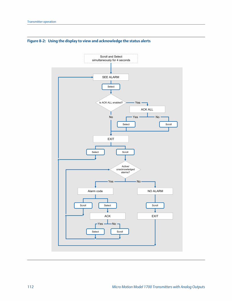
Using the display to view and acknowledge the status alertsFigure 8-2:
SEE ALARM
Select
Is ACK ALL enabled?
Scroll and Selectsimultaneously for 4 seconds
Yes
ACK ALL
No NoYes
Select Scroll
EXIT
Select Scroll
Active/unacknowledged
alarms?
Yes No
Alarm code NO ALARM
Scroll ScrollSelect
ACK EXIT
Yes No
Select Scroll
Transmitter operation
112 Micro Motion Model 1700 Transmitters with Analog Outputs

Postrequisites
• To clear the following alerts, you must correct the problem, acknowledge the alert,then power-cycle the transmitter: A001, A002, A010, A011, A012, A013, A018,A019, A022, A023, A024, A025, A028, A029, A031.
• For all other alerts:
- If the alert is inactive when it is acknowledged, it will be removed from the list.
- If the alert is active when it is acknowledged, it will be removed from the listwhen the alert condition clears.
8.4.2 View and acknowledge alerts using ProLink IIIYou can view a list containing all alerts that are active, or inactive but unacknowledged.From this list, you can acknowledge individual alerts or choose to acknowledge all alerts atonce.
1. View alerts on the ProLink III main screen under Alerts.
All active or unacknowledged alerts are listed, and displayed according to thefollowing categories:
Category Description
Failed: Fix Now A meter failure has occurred and must be addressed immediately.
Maintenance: Fix Soon A condition has occurred that can be fixed at a later time.
Advisory: Informational A condition has occurred, but requires no maintenance from you.
Notes
• All fault alerts are displayed in the Failed: Fix Now category.
• All information alerts are displayed in either the Maintenance: Fix Soon category or theAdvisory: Informational category. The category assignment is hard-coded.
• The transmitter automatically filters out alerts with Alert Severity set to Ignore.
2. To acknowledge a single alert, check the Ack checkbox for that alert. Toacknowledge all alerts at once, click Ack All.
Postrequisites
• To clear the following alerts, you must correct the problem, acknowledge the alert,then power-cycle the transmitter: A001, A002, A010, A011, A012, A013, A018,A019, A022, A023, A024, A025, A028, A029, A031.
• For all other alerts:
- If the alert is inactive when it is acknowledged, it will be removed from the list.
- If the alert is active when it is acknowledged, it will be removed from the listwhen the alert condition clears.
Transmitter operation
Configuration and Use Manual 113

8.4.3 View alerts using the Field CommunicatorYou can view a list containing all alerts that are active, or inactive but unacknowledged.
• To view active or unacknowledged alerts, choose Service Tools > Alerts.
All active alerts and unacknowledged alerts are listed.
NoteOnly Fault and Informational alerts are listed. The transmitter automatically filters out alertswith Status Alert Severity set to Ignore.
• To refresh the list, choose Service Tools > Alerts > Refresh Alerts.
8.5 Read totalizer and inventory values
Display To read a totalizer or inventory value from the display, it must be configured as a display
variable.
ProLink III View the desired variable on the main screen under Process Variables.
Field Communicator Service Tools > Variables > Totalizer Control
Overview
Totalizers keep track of the total amount of mass or volume measured by the transmittersince the last totalizer reset. Inventories keep track of the total amount of mass or volumemeasured by the transmitter since the last inventory reset.
TipYou can use the inventories to keep a running total of mass or volume across multiple totalizerresets.
8.6 Start and stop totalizers and inventories
Display See Section 8.6.1.
ProLink III Device Tools > Totalizer Control > Totalizer and Inventories > Start All Totals
Device Tools > Totalizer Control > Totalizer and Inventories > Stop All Totals
Field Communicator Service Tools > Variables > Totalizer Control > All Totalizers > Start Totalizers
Service Tools > Variables > Totalizer Control > All Totalizers > Stop Totalizers
Transmitter operation
114 Micro Motion Model 1700 Transmitters with Analog Outputs

Overview
When you start a totalizer, it tracks process measurement. In a typical application, its valueincreases with flow. When you stop a totalizer, it stops tracking process measurement andits value does not change with flow. Inventories are started and stopped automatically,when totalizers are started and stopped.
ImportantTotalizers and inventories are started or stopped as a group. When you start any totalizer, all othertotalizers and all inventories are started simultaneously. When you stop any totalizer, all othertotalizers and all inventories are stopped simultaneously. You cannot start or stop inventoriesdirectly.
8.6.1 Start and stop totalizers and inventories using thedisplayPrerequisites
The Totalizer Start/Stop display function must be enabled.
At least one totalizer must be configured as a display variable.
Procedure
• To start all totalizers and inventories using the display:
1. Scroll until the word TOTAL appears in the lower left corner of the display.
ImportantBecause all totalizers are started or stopped together, it does not matter which total youuse.
2. Select.
3. Scroll until START appears beneath the current totalizer value.
Exit displays beneath the current totalizer value.
4. Select.
5. Select again to confirm.
6. Scroll to EXIT.
• To stop all totalizers and inventories using the display:
1. Scroll until the word TOTAL appears in the lower left corner of the display.
ImportantBecause all totalizers are started or stopped together, it does not matter which total youuse.
2. Select.
Transmitter operation
Configuration and Use Manual 115
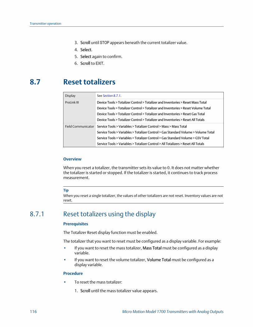
3. Scroll until STOP appears beneath the current totalizer value.
4. Select.
5. Select again to confirm.
6. Scroll to EXIT.
8.7 Reset totalizers
Display See Section 8.7.1.
ProLink III Device Tools > Totalizer Control > Totalizer and Inventories > Reset Mass Total
Device Tools > Totalizer Control > Totalizer and Inventories > Reset Volume Total
Device Tools > Totalizer Control > Totalizer and Inventories > Reset Gas Total
Device Tools > Totalizer Control > Totalizer and Inventories > Reset All Totals
Field Communicator Service Tools > Variables > Totalizer Control > Mass > Mass Total
Service Tools > Variables > Totalizer Control > Gas Standard Volume > Volume Total
Service Tools > Variables > Totalizer Control > Gas Standard Volume > GSV Total
Service Tools > Variables > Totalizer Control > All Totalizers > Reset All Totals
Overview
When you reset a totalizer, the transmitter sets its value to 0. It does not matter whetherthe totalizer is started or stopped. If the totalizer is started, it continues to track processmeasurement.
TipWhen you reset a single totalizer, the values of other totalizers are not reset. Inventory values are notreset.
8.7.1 Reset totalizers using the displayPrerequisites
The Totalizer Reset display function must be enabled.
The totalizer that you want to reset must be configured as a display variable. For example:
• If you want to reset the mass totalizer, Mass Total must be configured as a displayvariable.
• If you want to reset the volume totalizer, Volume Total must be configured as adisplay variable.
Procedure
• To reset the mass totalizer:
1. Scroll until the mass totalizer value appears.
Transmitter operation
116 Micro Motion Model 1700 Transmitters with Analog Outputs

2. Select.
Exit displays beneath the current totalizer value.
3. Scroll until Reset displays beneath the current totalizer value.
4. Select.
Reset and Yes? alternately flash beneath the current totalizer value.
5. Select again to confirm.
6. Scroll to EXIT.
7. Select.
• To reset the volume totalizer:
1. Scroll until the volume totalizer value appears.
2. Select.
Exit displays beneath the current totalizer value.
3. Scroll until Reset displays beneath the current totalizer value.
4. Select.
Reset and Yes? alternately flash beneath the current totalizer value.
5. Select again to confirm.
6. Scroll to EXIT.
7. Select.
• To reset the gas standard volume totalizer:
1. Scroll until the gas standard volume totalizer value appears.
2. Select.
Exit displays beneath the current totalizer value.
3. Scroll until Reset displays beneath the current totalizer value.
4. Select.
Reset and Yes? alternately flash beneath the current totalizer value.
5. Select again to confirm.
6. Scroll to EXIT.
7. Select.
Transmitter operation
Configuration and Use Manual 117
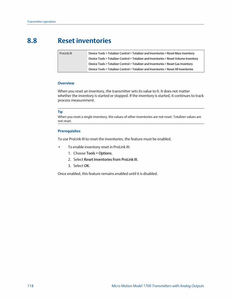
8.8 Reset inventories
ProLink III Device Tools > Totalizer Control > Totalizer and Inventories > Reset Mass Inventory
Device Tools > Totalizer Control > Totalizer and Inventories > Reset Volume Inventory
Device Tools > Totalizer Control > Totalizer and Inventories > Reset Gas Inventory
Device Tools > Totalizer Control > Totalizer and Inventories > Reset All Inventories
Overview
When you reset an inventory, the transmitter sets its value to 0. It does not matterwhether the inventory is started or stopped. If the inventory is started, it continues to trackprocess measurement.
TipWhen you reset a single inventory, the values of other inventories are not reset. Totalizer values arenot reset.
Prerequisites
To use ProLink III to reset the inventories, the feature must be enabled.
• To enable inventory reset in ProLink III:
1. Choose Tools > Options.
2. Select Reset Inventories from ProLink III.
3. Select OK.
Once enabled, this feature remains enabled until it is disabled.
Transmitter operation
118 Micro Motion Model 1700 Transmitters with Analog Outputs

9 Measurement supportTopics covered in this chapter:
• Options for measurement support
• Use Smart Meter Verification (SMV)
• Use PVR, TBR, and TMR
• Piecewise linearization (PWL) for calibrating gas meters
• Zero the meter
• Validate the meter
• Perform a (standard) D1 and D2 density calibration
• Perform a D3 and D4 density calibration (T‐Series sensors only)
• Perform temperature calibration
9.1 Options for measurement supportMicro Motion provides several measurement support procedures to help you evaluate andmaintain your flowmeter's accuracy.
The following methods are available:
• Smart Meter Verification (SMV) evaluates the structural integrity of the sensor tubesby comparing current tube stiffness to the stiffness measured at the factory.Stiffness is defined as the load per unit deflection, or force divided by displacement.Because a change in structural integrity changes the sensor’s response to mass anddensity, this value can be used as an indicator of measurement performance.
• Meter validation compares flowmeter measurements reported by the transmitter toan external measurement standard. Meter validation requires one data point.
• Calibration establishes the relationship between a process variable and the signalproduced at the sensor. You can calibrate the flowmeter for zero, density, andtemperature. Density and temperature calibration require two data points (low andhigh) and an external measurement for each.
Tips
• Perform SMV at regular intervals to get the best data on your meter's performance.
• To prove the meter against a regulatory standard, or to correct measurement error, usemeter validation and meter factors.
• Before performing a field calibration, contact customer support to see if there is analternative. In many cases, field calibrations have a negative effect on measurement accuracy.
Measurement support
Configuration and Use Manual 119
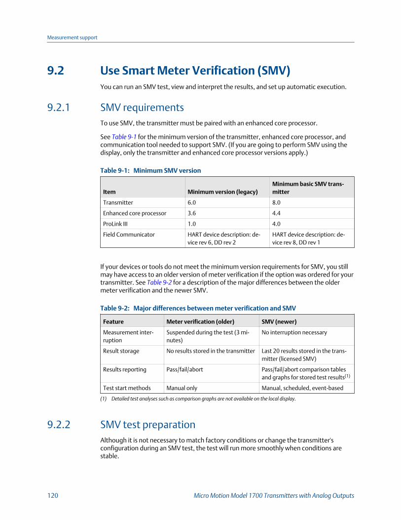
9.2 Use Smart Meter Verification (SMV)You can run an SMV test, view and interpret the results, and set up automatic execution.
9.2.1 SMV requirementsTo use SMV, the transmitter must be paired with an enhanced core processor.
See Table 9‐1 for the minimum version of the transmitter, enhanced core processor, andcommunication tool needed to support SMV. (If you are going to perform SMV using thedisplay, only the transmitter and enhanced core processor versions apply.)
Minimum SMV versionTable 9-1:
Item Minimum version (legacy)Minimum basic SMV trans-mitter
Transmitter 6.0 8.0
Enhanced core processor 3.6 4.4
ProLink III 1.0 4.0
Field Communicator HART device description: de-vice rev 6, DD rev 2
HART device description: de-vice rev 8, DD rev 1
If your devices or tools do not meet the minimum version requirements for SMV, you stillmay have access to an older version of meter verification if the option was ordered for yourtransmitter. See Table 9‐2 for a description of the major differences between the oldermeter verification and the newer SMV.
Major differences between meter verification and SMVTable 9-2:
Feature Meter verification (older) SMV (newer)
Measurement inter-ruption
Suspended during the test (3 mi-nutes)
No interruption necessary
Result storage No results stored in the transmitter Last 20 results stored in the trans-mitter (licensed SMV)
Results reporting Pass/fail/abort Pass/fail/abort comparison tablesand graphs for stored test results(1)
Test start methods Manual only Manual, scheduled, event-based
(1) Detailed test analyses such as comparison graphs are not available on the local display.
9.2.2 SMV test preparationAlthough it is not necessary to match factory conditions or change the transmitter'sconfiguration during an SMV test, the test will run more smoothly when conditions arestable.
Measurement support
120 Micro Motion Model 1700 Transmitters with Analog Outputs

SMV has an output mode called Continuous Measurement that allows the transmitter to keepmeasuring while the test is in progress. If you choose to run the test in Last Measured Valueor Fault modes instead, the transmitter outputs will be held constant for the two minuteduration of the test. If control loops depend on transmitter outputs, take appropriateaction.
Avoid process instability during the test. If conditions are too unstable, the SMV test willabort. To maximize process stability:
• Maintain a constant fluid pressure and temperature.
• Avoid changes to fluid composition, e.g., two-phase flow or settling.
• Maintain a constant flow rate.
Tips
• The SMV test runs best when flow is stopped through the sensor.
• SMV is not affected by any configured transmitter parameters for flow, density, ortemperature.
9.2.3 Run SMV
Run an SMV test using the display1. Navigate to the Smart Meter Verification menu.
SMV – Top-level menuFigure 9-1:
Scroll and Select simultaneously for 4 seconds
ENTER METER VERFY
Scroll
RUN VERFY RESULTS READ SCHEDULE VERFY
Select
EXITScroll Scroll Scroll
Scroll Select
Select Select Select
2. Choose Run Verify.
3. Choose Outputs and select the desired output behavior.
Option Description
ContinueMeasr
During the test, all outputs will continue to report their assigned process var-iable. The test will run for approximately 90 seconds.
Fault During the test, all outputs will go to their configured fault action. The testwill run for approximately 140 seconds.
Measurement support
Configuration and Use Manual 121
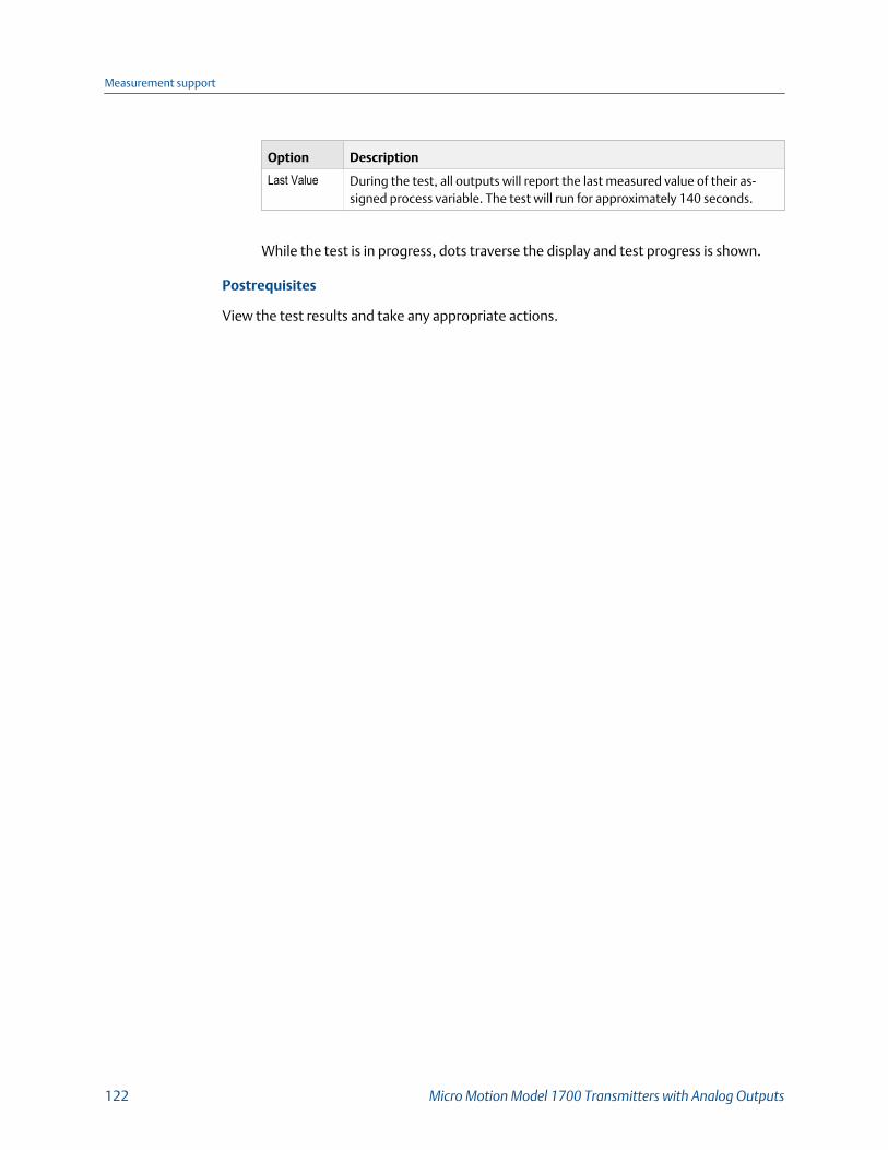
Option Description
Last Value During the test, all outputs will report the last measured value of their as-signed process variable. The test will run for approximately 140 seconds.
While the test is in progress, dots traverse the display and test progress is shown.
Postrequisites
View the test results and take any appropriate actions.
Measurement support
122 Micro Motion Model 1700 Transmitters with Analog Outputs

SMV flowchart: Running a test using the display
Running an SMV test using the displayFigure 9-2:
OUTPUTS
ARE YOU SURE/YES?
. . . . . . . . . . . . . . . x%
PASS VERFY ABORTED VERFYCAUTION VERFY
Fail
Abort
RERUN/YES?
Yes No
Correct condition
RUN VERFY
CONTINUE MEASR FAULT LAST VALUE
Select
Scroll Scroll
Scroll
Select
Scroll
RESULTS VIEW/YES?
Select
Scroll Scroll
Select Select
Select
Select
Select SENSOR ABORT/YES?
SelectScroll
Abort Type
Scroll
Scroll Select
To Runcount(see Results Read)
Test resultPass
EXITScroll
EXITScroll
To Enter Meter Verfy
Run an SMV test using ProLink III1. Choose Device Tools > Diagnostics > Meter Verification > Run Test.
Measurement support
Configuration and Use Manual 123

You may need to wait a few seconds while ProLink III synchronizes its database withthe transmitter data.
2. Enter any desired information on the Test Definition screen, and click Next.
All information on this screen is optional.
3. Choose the desired output behavior.
Option Description
Continue Measur-ing
During the test, all outputs will continue to report their assigned processvariable. The test will run for approximately 90 seconds.
Held at Last Value During the test, all outputs will report the last measured value of their as-signed process variable. The test will run for approximately 140 seconds.
Held at Fault During the test, all outputs will go to their configured fault action. Thetest will run for approximately 140 seconds.
4. Press Start.
Test progress is displayed on the screen.
Postrequisites
View the test results and take any appropriate actions. You can also print the report.
Run an SMV test using the Field Communicator1. Navigate to the Smart Meter Verification menu:
• Overview > Shortcuts > Meter Verification
• Service Tools > Maintenance > Routine Maintenance > Meter Verification
2. Choose Manual Verification.
3. Choose Start.
4. Set output behavior as desired, and press OK if prompted.
Option Description
Continue Measuring During the test, all outputs will continue to report their assigned proc-ess variable. The test will run for approximately 90 seconds.
Outputs Held at LastValue
During the test, all outputs will report the last measured value of theirassigned process variable. The test will run for approximately140 seconds.
Outputs Held at Fault During the test, all outputs will go to their configured fault action. Thetest will run for approximately 140 seconds.
Test progress is displayed on the screen.
Measurement support
124 Micro Motion Model 1700 Transmitters with Analog Outputs

Postrequisites
View the test results and take any appropriate actions.
9.2.4 View test dataYou can view the results of the current test. You can also view results from previous tests.You must use ProLink III to view test results.
ImportantYou can view previous test results and see detailed test reports only if SMV is licensed.
The transmitter stores the following information about the previous twenty SMV tests:
• Powered-on hours at the time of the test.
• Test result (Pass, Fail, Abort).
• Abort code, if applicable.
In addition, ProLink III provides a detailed test reporting and analysis framework. Thisinformation is stored on the PC where ProLink III is installed for tests that were run only onthat PC. It includes:
• Timestamp from the PC clock
• Current flowmeter identification data
• Current flow and density configuration parameters
• Current zero values
• Current process values for mass flow rate, volume flow rate, density, temperature,and external pressure
• Customer and test descriptions (if entered by the user)
You can use ProLink III to run a test that displays a test result chart and a test report at thecompletion of the test. On-screen directions are provided to manipulate the test data orexport the data to a CSV file for offline analysis.
View test result data using the display1. If you have just run a test, results are displayed automatically at the end of the test.
2. If SMV is licensed, and you want to view results from previous tests:
a. Navigate to the Smart Meter Verification menu.
Measurement support
Configuration and Use Manual 125

SMV – Top-level menuFigure 9-3:
Scroll and Select simultaneously for 4 seconds
ENTER METER VERFY
Scroll
RUN VERFY RESULTS READ SCHEDULE VERFY
Select
EXITScroll Scroll Scroll
Scroll Select
Select Select Select
b. Scroll to Results Read and press Select.
The runcount of the most recent test is displayed.
c. To view data for this test, press Select, then press Scroll to scroll through testdata.
d. To select a different test, press Scroll, then press Select when the transmitterdisplays Results More?. When the desired test appears, as identified by runcount,press Select.
Measurement support
126 Micro Motion Model 1700 Transmitters with Analog Outputs
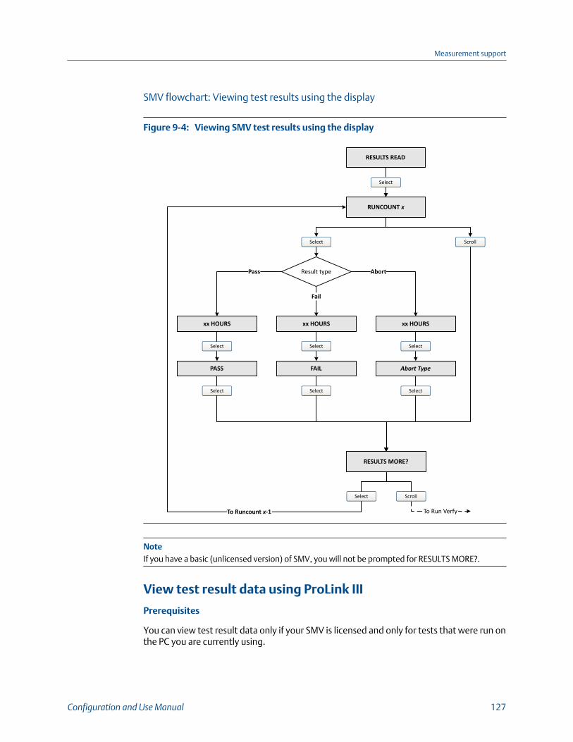
SMV flowchart: Viewing test results using the display
Viewing SMV test results using the displayFigure 9-4:
RESULTS READ
Select
RUNCOUNT x
Select
xx HOURS
Select
PASS
Select
RESULTS MORE?
Scroll
To Run Verfy
Pass
Select Scroll
Result type
Fail
Abort
xx HOURS
Select
FAIL
xx HOURS
Abort Type
To Runcount x-1
Select
SelectSelect
NoteIf you have a basic (unlicensed version) of SMV, you will not be prompted for RESULTS MORE?.
View test result data using ProLink III
Prerequisites
You can view test result data only if your SMV is licensed and only for tests that were run onthe PC you are currently using.
Measurement support
Configuration and Use Manual 127

Procedure
1. Choose Device Tools > Diagnostics > Meter Verification and click Previous TestResults.
The chart shows test results for all tests stored in the ProLink III database.
2. (Optional) Click Next to view and print a test report.
3. (Optional) Click Export Data to CSV File to save the data to a file on your PC.
View test result data using the Field Communicator
Prerequisites
You can view test result data only if your SMV is licensed.
Procedure
1. Navigate to the Smart Meter Verification menu:
• Overview > Shortcuts > Meter Verification
• Service Tools > Maintenance > Routine Maintenance > Meter Verification
2. (Optional) If the Field Communicator database is out of date, choose Upload ResultsData from Device.
3. To view data from the most recent test, choose Most Recent Test Results.
4. To view data for all tests in the Field Communicator database:
a. Press Show Results Table.
Data from the most recent test is displayed.
b. Press OK to scroll through data from previous tests.
c. To exit the results table, press Abort.
Understanding SMV resultsWhen the SMV test is completed, the result is reported as Pass, Fail, or Abort. (Some toolsreport the Fail result as Advisory instead.)
Pass Smart Meter Verification does a statistical check between the factory baselinevalue and the current Smart Meter Verification result. Pass indicates that the twovalues are statistically the same.
Fail The current SMV value is statistically different than the factory baseline value.
• If the meter passes the second test, the first result can be ignored.
• If the meter fails the second test, the flow tubes may be damaged. Callcustomer support.
Abort A problem occurred with the meter verification test (such as process instability)or you stopped the test manually. See Table 9‐3 for a list of abort codes, adescription of each code, and possible actions you can take in response.
Measurement support
128 Micro Motion Model 1700 Transmitters with Analog Outputs

SMV abort codesTable 9-3:
Code Description Recommended actions
1 User-initiated abort None required. Wait 15 seconds before starting an-other test.
3 Frequency drift Ensure that temperature, flow, and density are sta-ble, and rerun the test.
5 High drive gain Ensure that flow is stable, minimize entrained gas,and rerun the test.
8 Unstable flow Check factors that could cause process instability,then rerun the test. To maximize process stability:• Maintain a constant fluid pressure and tempera-
ture.• Avoid changes to fluid composition, such as
two-phase flow or settling.• Maintain a constant flow rate.
12 There is a fault present andSMV cannot run
View the Alerts present on the device and take anynecessary actions to clear them.
13 No factory reference data formeter verification test per-formed on air
Contact customer service.
14 No factory reference data formeter verification test per-formed on water
Contact customer service.
15 No configuration data formeter verification
Contact customer service.
Other General abort Repeat the test. If the test aborts again, contactcustomer service.
9.2.5 Schedule automatic execution of the SMV testYou can set up and run a single test at a user-defined future time. You can also set up andrun tests on a regular schedule.
Manage scheduled test execution using the display1. Navigate to the Smart Meter Verification menu.
Measurement support
Configuration and Use Manual 129

SMV – Top-level menuFigure 9-5:
Scroll and Select simultaneously for 4 seconds
ENTER METER VERFY
Scroll
RUN VERFY RESULTS READ SCHEDULE VERFY
Select
EXITScroll Scroll Scroll
Scroll Select
Select Select Select
2. Scroll to Schedule Verfy and press Select.
3. To schedule a single test or the first test in recurring execution:
a. Scroll to Set Next and press Select.
b. Enter the number of hours that the transmitter will wait before beginning thetest.
4. To schedule recurring execution:
a. Scroll to Set Recur and press Select.
b. Enter the number of hours that will elapse between tests.
5. To disable scheduled execution:
• To disable execution of a single scheduled test, set Set Next to 0.
• To disable recurring execution, set Set Recur to 0.
• To disable all scheduled execution, choose Turn Off Sched when you enter theSmart Meter Verification menu.
Measurement support
130 Micro Motion Model 1700 Transmitters with Analog Outputs

SMV flowchart: Scheduling test execution using the display
Scheduling SMV test execution using the displayFigure 9-6:
SCHEDULE VERFY
Select
SAVE/YES?
TURN OFF SCHED/YES?
SET NEXT
Select
Select
Schedule set? Yes
Schedule deleted
Scroll
HOURS LEFT
SelectScroll
xx HOURS
SET RECUR
No
SCHED IS OFF
xx HOURS
Select
Scroll
No Yes
Select
xx HOURS
Select
SAVE/YES?
Scroll
No Yes
Scroll Scroll EXIT
Scroll Select
Select
Scroll
Manage scheduled test execution using ProLink III1. Choose Device Tools > Diagnostics > Meter Verification > Schedule Meter
Verification.
2. To schedule a single test or the first test in recurring execution, specify a value forHours Until Next Run.
Measurement support
Configuration and Use Manual 131

3. To schedule recurring execution, specify a value for Hours Between Recurring Runs.
4. To disable scheduled execution:
• To disable execution of a single scheduled test, set Hours Until Next Run to 0.
• To disable recurring execution, set Hours Between Recurring Runs to 0.
• To disable all scheduled execution, click Disable Scheduled Execution.
Manage scheduled test execution using theField Communicator1. Navigate to the Smart Meter Verification menu:
• Overview > Shortcuts > Meter Verification
• Service Tools > Maintenance > Routine Maintenance > Meter Verification
2. Choose Automatic Verification.
3. To schedule a single test or the first test in recurring execution, specify a value forHrs Until Next Run.
4. To schedule recurring execution, specify a value for Set Recurring Hours.
5. To disable scheduled execution:
• To disable execution of a single scheduled test, set Hrs Until Next Run to 0.
• To disable recurring execution, set Set Recurring Hours to 0.
• To disable all scheduled execution, choose Turn Off Schedule.
9.3 Use PVR, TBR, and TMRFor detailed information about Production Volume Reconciliation (PVR), Transient MistRemediation (TMR), and Transient Bubble Remediation (TBR), see the Micro Motion® Oiland Gas Production Applications manual.
RestrictionPVR, TBR, and TMR are available only with a transmitter that is ordered with one of these softwareoptions:
• An 800 Enhanced Core Processor version 4.4 and later
• HART with HART 7 enabled in order to view process variables over HART (default)
RestrictionPVR, TBR, and TMR process variables are available only over HART with HART 7 enabled(default). PVR, TBR, and TMR parameters cannot be configured with HART.
Measurement support
132 Micro Motion Model 1700 Transmitters with Analog Outputs
9.3.1 PVR, TBR, and TMR applicationsPVR, TBR, and TMR are applications designed to provide more accurate process data in thepresence of multiple phases. For example, if bubbles are present in the process fluid, or theprocess fluid is flashing, the volume measurements are often incorrect.
Production Volume Reconciliation (PVR)
• Provides oil and water volumes through density-based calculations for both line andreference conditions
• Detects bubble entrainment or flashing in the sensor, and can correct volumesaccordingly
• Best for undersized three-phase separators that frequently have intermittent gas orwater contamination in the oil leg
• Offers a simple, low-cost solution for net oil and net water measurement for two-phase separators
Transient Bubble Remediation (TBR)
• Used with single-component liquid streams that may experience intermittent lowlevels of gas entrainment, that is, gas carryunder
• Enables accurate measurement of a single fluid during periods of entrained gas byproviding a substitute density value based on the immediately preceding processdensity (standard configuration)
• Tracks total time of aerated flow to assist in diagnosing process issues that maycause aeration
Transient Mist Remediation (TMR)
• Used with gas streams that may experience intermittent low levels of liquidentrainment, i.e., liquid carry-over
• Allows gas measurement to continue during periods of entrained liquid (mist) byproviding a substitute flow rate value based on the immediately preceding processflow rate
• Returns to reporting the measured flow rate when the mist interval is over,increased or decreased by a maximum of 10%, until flow totals are appropriatelyadjusted for the unmeasured flow
• Provides an indication of the amount of time that liquid was present in the stream —identifying process improvements to reduce gas stream contamination
Measurement support
Configuration and Use Manual 133
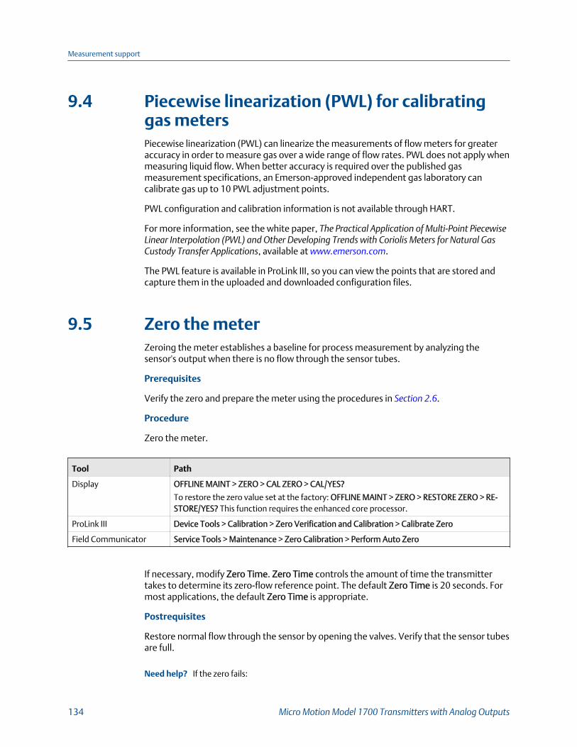
9.4 Piecewise linearization (PWL) for calibratinggas metersPiecewise linearization (PWL) can linearize the measurements of flow meters for greateraccuracy in order to measure gas over a wide range of flow rates. PWL does not apply whenmeasuring liquid flow. When better accuracy is required over the published gasmeasurement specifications, an Emerson-approved independent gas laboratory cancalibrate gas up to 10 PWL adjustment points.
PWL configuration and calibration information is not available through HART.
For more information, see the white paper, The Practical Application of Multi‐Point PiecewiseLinear Interpolation (PWL) and Other Developing Trends with Coriolis Meters for Natural GasCustody Transfer Applications, available at www.emerson.com.
The PWL feature is available in ProLink III, so you can view the points that are stored andcapture them in the uploaded and downloaded configuration files.
9.5 Zero the meterZeroing the meter establishes a baseline for process measurement by analyzing thesensor's output when there is no flow through the sensor tubes.
Prerequisites
Verify the zero and prepare the meter using the procedures in Section 2.6.
Procedure
Zero the meter.
Tool Path
Display OFFLINE MAINT > ZERO > CAL ZERO > CAL/YES?
To restore the zero value set at the factory: OFFLINE MAINT > ZERO > RESTORE ZERO > RE-STORE/YES? This function requires the enhanced core processor.
ProLink III Device Tools > Calibration > Zero Verification and Calibration > Calibrate Zero
Field Communicator Service Tools > Maintenance > Zero Calibration > Perform Auto Zero
If necessary, modify Zero Time. Zero Time controls the amount of time the transmittertakes to determine its zero-flow reference point. The default Zero Time is 20 seconds. Formost applications, the default Zero Time is appropriate.
Postrequisites
Restore normal flow through the sensor by opening the valves. Verify that the sensor tubesare full.
Need help? If the zero fails:
Measurement support
134 Micro Motion Model 1700 Transmitters with Analog Outputs
• Verify that there is no flow through the sensor, then retry.
• Remove or reduce sources of electromechanical noise, then retry.
• Set Zero Time to a lower value, then retry.
• If the zero continues to fail, contact customer service.
9.6 Validate the meter
Display OFF-LINE MAINT > CONFG > UNITS > MTR F
ProLink III Device Tools > Configuration > Process Measurement > Flow
Device Tools > Configuration > Process Measurement > Density
Field Communicator Configure > Manual Setup > Measurements > Flow
Configure > Manual Setup > Measurements > Density
Overview
Meter validation compares flowmeter measurements reported by the transmitter to anexternal measurement standard. If the transmitter value for mass flow, volume flow, ordensity measurement is significantly different from the external measurement standard,you may want to adjust the corresponding meter factor. The flowmeter’s actualmeasurement is multiplied by the meter factor, and the resulting value is reported andused in further processing.
Prerequisites
Identify the meter factor(s) that you will calculate and set. You may set any combination ofthe three meter factors: mass flow, volume flow, and density. Note that all three meterfactors are independent:
• The meter factor for mass flow affects only the value reported for mass flow.
• The meter factor for density affects only the value reported for density.
• The meter factor for volume flow affects only the value reported for volume flow orgas standard volume flow.
ImportantTo adjust volume flow, you must set the meter factor for volume flow. Setting a meter factor formass flow and a meter factor for density will not produce the desired result. The volume flowcalculations are based on original mass flow and density values, before the corresponding meterfactors have been applied.
If you plan to calculate the meter factor for volume flow, be aware that validating volumein the field may be expensive, and the procedure may be hazardous for some processfluids. Therefore, because volume is inversely proportional to density, an alternative todirect measurement is to calculate the meter factor for volume flow from the meter factorfor density. See Section 9.6.1 for instructions on this method.
Measurement support
Configuration and Use Manual 135
Obtain a reference device (external measurement device) for the appropriate processvariable.
ImportantFor good results, the reference device must be highly accurate.
Procedure
1. Determine the meter factor as follows:
a. Set the meter factor to 1 to take a sample measurement.
b. Measure the same sample using the reference device.
c. Calculate the meter factor using the following formula:
NewMeterFactor = ConfiguredMeterFactorReferenceMeasurementFlowmeterMeasurement
2. Ensure that the calculated meter factor does not fall outside 0.98 and 1.02. If themeter factor is outside these limits, contact customer service.
3. Configure the meter factor in the transmitter.
Example: Calculating the meter factor for mass flow
The flowmeter is installed and validated for the first time. The mass flow measurementfrom the transmitter is 250.27 lb. The mass flow measurement from the reference deviceis 250 lb. The mass flow meter factor is calculated as follows:
MeterFactorMassFlow = 1250
250.27= 0.9989
The first meter factor for mass flow is 0.9989.
One year later, the flowmeter is validated again. The mass flow measurement from thetransmitter is 250.07 lb. The mass flow measurement from the reference device is250.25 lb. The new mass flow meter factor is calculated as follows:
MeterFactorMassFlow = 0.9989250.25250.07
= 0.9996
The new meter factor for mass flow is 0.9996.
9.6.1 Alternate method for calculating the meter factor forvolume flowThe alternate method for calculating the meter factor for volume flow is used to avoid thedifficulties that may be associated with the standard method.
This alternate method is based on the fact that volume is inversely proportional to density.It provides partial correction of the volume flow measurement by adjusting for the portionof the total offset that is caused by the density measurement offset. Use this method onlywhen a volume flow reference is not available, but a density reference is available.
Measurement support
136 Micro Motion Model 1700 Transmitters with Analog Outputs
Procedure
1. Calculate the meter factor for density, using the standard method (see Section 9.6).
2. Calculate the meter factor for volume flow from the meter factor for density:
MeterFactorVolume =1
MeterFactorDensity
NoteThe following equation is mathematically equivalent to the first equation. You may usewhichever version you prefer.
MeterFactorVolume = ConfiguredMeterFactorDensityDensityFlowmeter
DensityReference Device
3. Ensure that the calculated meter factor does not fall outside 0.98 and 1.02. If themeter factor is outside these limits, contact customer service.
4. Configure the meter factor for volume flow in the transmitter.
9.7 Perform a (standard) D1 and D2 densitycalibrationDensity calibration establishes the relationship between the density of the calibrationfluids and the signal produced at the sensor. Density calibration includes the calibration ofthe D1 (low-density) and D2 (high-density) calibration points.
ImportantMicro Motion flowmeters are calibrated at the factory, and normally do not need to be calibrated inthe field. Calibrate the flowmeter only if you must do so to meet regulatory requirements. Contactcustomer support before calibrating the flowmeter.
TipUse meter validation and meter factors, rather than calibration, to prove the meter against aregulatory standard or to correct measurement error.
Prerequisites
• During density calibration, the sensor must be completely filled with the calibrationfluid, and flow through the sensor must be at the lowest rate allowed by yourapplication. This is usually accomplished by closing the shutoff valve downstreamfrom the sensor, then filling the sensor with the appropriate fluid.
• D1 and D2 density calibration require a D1 (low-density) fluid and a D2 (high-density) fluid. You may use air and water.
Measurement support
Configuration and Use Manual 137
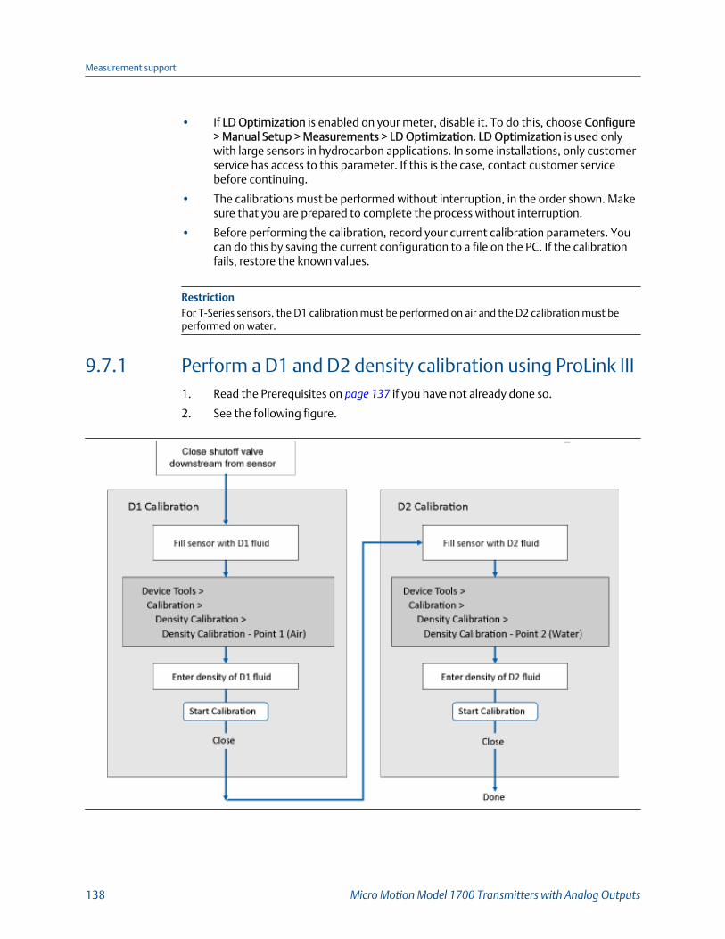
• If LD Optimization is enabled on your meter, disable it. To do this, choose Configure> Manual Setup > Measurements > LD Optimization. LD Optimization is used onlywith large sensors in hydrocarbon applications. In some installations, only customerservice has access to this parameter. If this is the case, contact customer servicebefore continuing.
• The calibrations must be performed without interruption, in the order shown. Makesure that you are prepared to complete the process without interruption.
• Before performing the calibration, record your current calibration parameters. Youcan do this by saving the current configuration to a file on the PC. If the calibrationfails, restore the known values.
RestrictionFor T-Series sensors, the D1 calibration must be performed on air and the D2 calibration must beperformed on water.
9.7.1 Perform a D1 and D2 density calibration using ProLink III1. Read the Prerequisites on page 137 if you have not already done so.
2. See the following figure.
Measurement support
138 Micro Motion Model 1700 Transmitters with Analog Outputs

Postrequisites
If you disabled LD Optimization before the calibration procedure, re-enable it.
9.7.2 Perform a D1 and D2 density calibration using the FieldCommunicator1. Read the Prerequistes on page 137 if you have not already done so.
2. See the following figure.
Postrequisites
If you disabled LD Optimization before the calibration procedure, re-enable it.
Measurement support
Configuration and Use Manual 139
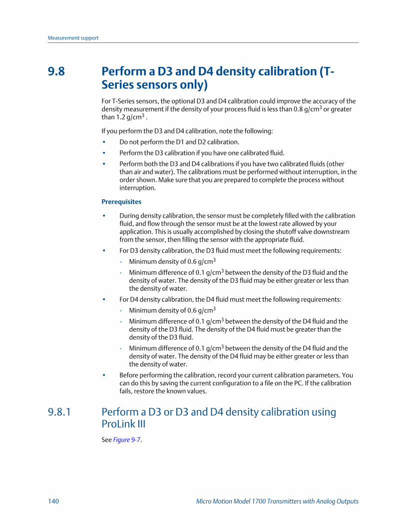
9.8 Perform a D3 and D4 density calibration (T-Series sensors only)For T-Series sensors, the optional D3 and D4 calibration could improve the accuracy of thedensity measurement if the density of your process fluid is less than 0.8 g/cm3 or greaterthan 1.2 g/cm3 .
If you perform the D3 and D4 calibration, note the following:
• Do not perform the D1 and D2 calibration.
• Perform the D3 calibration if you have one calibrated fluid.
• Perform both the D3 and D4 calibrations if you have two calibrated fluids (otherthan air and water). The calibrations must be performed without interruption, in theorder shown. Make sure that you are prepared to complete the process withoutinterruption.
Prerequisites
• During density calibration, the sensor must be completely filled with the calibrationfluid, and flow through the sensor must be at the lowest rate allowed by yourapplication. This is usually accomplished by closing the shutoff valve downstreamfrom the sensor, then filling the sensor with the appropriate fluid.
• For D3 density calibration, the D3 fluid must meet the following requirements:
- Minimum density of 0.6 g/cm3
- Minimum difference of 0.1 g/cm3 between the density of the D3 fluid and thedensity of water. The density of the D3 fluid may be either greater or less thanthe density of water.
• For D4 density calibration, the D4 fluid must meet the following requirements:
- Minimum density of 0.6 g/cm3
- Minimum difference of 0.1 g/cm3 between the density of the D4 fluid and thedensity of the D3 fluid. The density of the D4 fluid must be greater than thedensity of the D3 fluid.
- Minimum difference of 0.1 g/cm3 between the density of the D4 fluid and thedensity of water. The density of the D4 fluid may be either greater or less thanthe density of water.
• Before performing the calibration, record your current calibration parameters. Youcan do this by saving the current configuration to a file on the PC. If the calibrationfails, restore the known values.
9.8.1 Perform a D3 or D3 and D4 density calibration usingProLink IIISee Figure 9‐7.
Measurement support
140 Micro Motion Model 1700 Transmitters with Analog Outputs
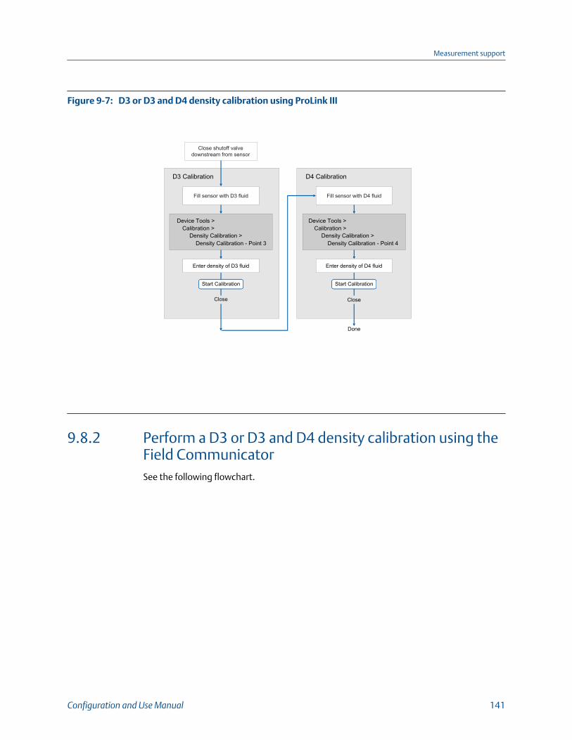
D3 or D3 and D4 density calibration using ProLink IIIFigure 9-7:
D3 Calibration
Close shutoff valvedownstream from sensor
Fill sensor with D3 fluid
Device Tools >Calibration >
Density Calibration >Density Calibration - Point 3
Device Tools >Calibration >
Density Calibration >Density Calibration - Point 4
Enter density of D3 fluid
Start Calibration Start Calibration
Enter density of D4 fluid
Close Close
Done
D4 Calibration
Fill sensor with D4 fluid
9.8.2 Perform a D3 or D3 and D4 density calibration using theField CommunicatorSee the following flowchart.
Measurement support
Configuration and Use Manual 141

D3 or D3 and D4 density calibration using the Field CommunicatorFigure 9-8:
D3 Calibration
Close shutoff valvedownstream from sensor Fill sensor with D3 fluid
On-Line Menu >Service Tools >
Maintenance >Density Calibration
Dens Pt 3 T-Series
Calibration Methodexecutes
Enter density of D3 fluid
OK
Calibration in Progressmessage
Density Calibration Completemessage
OK
Home
D4 Calibration
Fill sensor with D4 fluid
Dens Pt 4 T-Series
Calibration Methodexecutes
Enter density of D4 fluid
OK
Calibration in Progressmessage
Density Calibration Completemessage
OK
Home
Done
Service Tools >Maintenance >
Density Calibration
9.9 Perform temperature calibrationTemperature calibration establishes the relationship between the temperature of thecalibration fluids and the signal produced by the sensor.
Measurement support
142 Micro Motion Model 1700 Transmitters with Analog Outputs

Prerequisites
The temperature calibration is a two-part procedure: temperature offset calibration andtemperature slope calibration. The two parts must be performed without interruption, inthe order shown. Ensure that you are prepared to complete the process withoutinterruption. You will need a low-temperature calibration fluid and a high-temperaturecalibration fluid. You will not see the effect of the calibration until both the temperatureoffset calibration and the temperature slope calibration are complete.
ImportantConsult customer support before performing a temperature calibration. Under normalcircumstances, the temperature circuit is stable and should not need an adjustment.
9.9.1 Perform temperature calibration using the display1. Fill the sensor with the low-temperature fluid.
2. Wait until the sensor achieves thermal equilibrium.
3. Navigate to the calibration menu and enter it.
a. Activate Scroll and Select simultaneously.
b. Scroll to OFF-LINE MAINTand activate Select.
c. Scroll to OFF-LINE CAL and activate Select.
d. Scroll to CAL TEMP and activate Select.
4. Enter the temperature of the low-temperature fluid.
a. When CAL OFFSET TEMP is flashing, activate Select.
b. Enter the temperature value and save it.
5. Fill the sensor with the high-temperature fluid.
6. Wait until the sensor achieves thermal equilibrium.
7. Enter the temperature of the high-temperature fluid.
a. When CAL SLOPE TEMP is flashing, activate Select.
b. Enter the temperature value and save it.
8. Activate Scroll to view the new offset and slope values.
9. Activate Select to exit.
9.9.2 Perform temperature calibration using ProLink IIISee the following figure.
Measurement support
Configuration and Use Manual 143
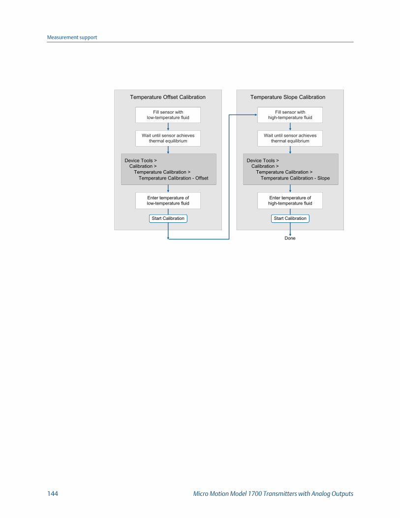
Temperature Offset Calibration
Wait until sensor achievesthermal equilibrium
Fill sensor withlow-temperature fluid
Device Tools >Calibration >
Temperature Calibration >Temperature Calibration - Offset
Enter temperature oflow-temperature fluid
Done
Temperature Slope Calibration
Start Calibration
Wait until sensor achievesthermal equilibrium
Fill sensor withhigh-temperature fluid
Device Tools >Calibration >
Temperature Calibration >Temperature Calibration - Slope
Enter temperature ofhigh-temperature fluid
Start Calibration
Measurement support
144 Micro Motion Model 1700 Transmitters with Analog Outputs

9.9.3 Perform temperature calibration using theField Communicator
Enter temperature of low-temperature fluid
Temperature Offset calibration
Next
Wait until sensor achieves thermal equilibrium
Fill sensor with low-temperature fluid
Calibration Complete
Temperature Slope calibration
Wait until sensor achieves thermal equilibrium
Fill sensor with high-temperature fluid
Done
Service Tools > Maintenance > Calibration >
Temperature Calibration Offset
Calibration in Progress
Next
Enter temperature of high-temperature fluid
Next
Calibration Complete
Service Tools > Maintenance > Calibration >
Temperature Calibration Slope
Calibration in Progress
Finish
Measurement support
Configuration and Use Manual 145

Measurement support
146 Micro Motion Model 1700 Transmitters with Analog Outputs
10 TroubleshootingTopics covered in this chapter:
• Status LED states
• Status alerts, causes, and recommendations
• Flow measurement problems
• Density measurement problems
• Temperature measurement problems
• Milliamp output problems
• Frequency Output problems
• Using sensor simulation for troubleshooting
• Check power supply wiring
• Check sensor‐to‐transmitter wiring
• Check grounding
• Perform loop tests
• Check the HART communication loop
• Check HART Address and mA Output Action
• Check HART burst mode
• Check the trimming of the mA Output
• Check Lower Range Value and Upper Range Value
• Check mA Output Fault Action
• Check for radio frequency interference (RFI)
• Check Frequency Output Scaling Method
• Check Frequency Output Fault Action
• Check Flow Direction
• Check the cutoffs
• Check for two‐phase flow (slug flow)
• Check the drive gain
• Check the pickoff voltage
• Check for internal electrical problems
• Check the core processor LED
• Perform a 700 core processor resistance test
Troubleshooting
Configuration and Use Manual 147

10.1 Status LED statesThe status LED on the transmitter indicates whether or not alerts are active. If alerts areactive, view the alert list to identify the alerts, then take appropriate action to correct thealert condition.
Your transmitter has a status LED only if it has a display.
If the transmitter has a display and LED Blinking is disabled, the status LED does not flash toindicate an unacknowledged alert.
Transmitter status reported by status LEDTable 10-1:
LED state Description Recommendation
Solid green No alerts are active. Continue with configuration or process meas-urement.
Flashing green (if ena-bled)
Unacknowledged corrected condition (noalert)
Continue with configuration or process meas-urement. Acknowledge the alert if you choose.
Solid yellow One or more low-severity alerts are active. A low-severity alert condition does not affectmeasurement accuracy or output behavior.You can continue with configuration or proc-ess measurement, but Micro Motion still rec-ommends identifying and resolving the alertcondition.
Flashing yellow (if ena-bled)
Calibration in progress, or Known Density Ver-ification in progress.
One or more low-severity alerts are active andhave not been acknowledged.
A low-severity alert condition does not affectmeasurement accuracy or output behavior.You can continue with configuration or proc-ess measurement, but Micro Motion still rec-ommends identifying and resolving the alertcondition.
Solid red One or more high-severity alerts are active. A high-severity alert condition affects meas-urement accuracy and output behavior. Re-solve the alert condition before continuing.
Flashing red (if ena-bled)
One or more high-severity alerts are activeand have not been acknowledged.
A high-severity alert condition affects meas-urement accuracy and output behavior. Re-solve the alert condition before continuing.Acknowledge the alert if you choose.
10.2 Status alerts, causes, and recommendations
Alert num-ber Alert title Possible cause Recommended actions
A001 EEPROM Error (CoreProcessor)
The core processor has experienceda memory error.
• Cycle power to the meter.• Replace the core processor.• Contact customer support.
Troubleshooting
148 Micro Motion Model 1700 Transmitters with Analog Outputs

Alert num-ber Alert title Possible cause Recommended actions
A002 RAM Error (Core Pro-cessor)
The core processor has experienceda memory error.
• Cycle power to the meter.• Replace the core processor.• Contact customer support.
A003 No Sensor Response The transmitter is not receiving oneor more basic electrical signals fromthe sensor.
This alert often occurs in conjunc-tion with Alert 102.
• Check the drive gain and the pickoffvoltage.
• Check the wiring between the sensorand the transmitter.
• Verify that internal wiring is secure andthat there are no internal electricalproblems.
• Check the integrity of the sensor tubes.• Perform sensor coil resistance checks.
A004 Temperature Over-range
The RTD resistance is out of rangefor the sensor. The tube RTD resist-ance is out of range for the sensor.
• Check your process conditions againstthe values reported by the device.
• Verify temperature characterization orcalibration parameters.
• Verify that internal wiring is secure andthat there are no internal electricalproblems.
• Check the wiring between the sensorand the transmitter.
• Contact customer support.
A005 Mass Flow RateOverrange
The measured flow rate is greaterthan the maximum flow rate of thesensor (ΔT greater than 200 µs).
• If other alerts are present, resolve thosealert conditions first. If the current alertpersists, continue with the recommen-ded actions.
• Check your process conditions againstthe values reported by the device.
• Check for two-phase flow.
A006 Characterization Re-quired
Calibration factors have not beenentered, or the sensor type is incor-rect, or the calibration factors areincorrect for the sensor type.
• Verify all of the characterization or cali-bration parameters. See the sensor tagor the calibration sheet for your meter.
• Verify the setting of the Sensor Type pa-rameter.
• If Sensor Type=Curved Tube, ensure thatno parameters specific to Straight Tubehave been set.
• Verify that internal wiring is secure andthat there are no internal electricalproblems.
• Replace the core processor.• Contact customer support.
Troubleshooting
Configuration and Use Manual 149

Alert num-ber Alert title Possible cause Recommended actions
A008 Density Overrange The line density is greater than10 g/cm3 (10000 kg/m3 ).
• If other alerts are present, resolve thosealert conditions first. If the current alertpersists, continue with the recommen-ded actions.
• Check for air in the flow tubes, tubesnot filled, foreign material in the tubes,coating in the tubes, or other processproblems.
• Check for two-phase flow.• Verify all of the characterization or cali-
bration parameters. See the sensor tagor the calibration sheet for your meter.
• Check the drive gain and the pickoffvoltage.
• Perform density calibration.• Contact customer support.
A009 Transmitter Initializ-ing/Warming Up
Transmitter is in power-up mode.
This alert often occurs in conjunc-tion with Alerts 14 and 26.
• Allow the meter to complete its power-up sequence. The alert should clear au-tomatically.
• If other alerts are present, resolve thosealert conditions first. If the current alertpersists, continue with the recommen-ded actions.
• Verify that the tubes are full of processfluid.
• Check the wiring between the sensorand the transmitter.
• Verify that the transmitter is receivingsufficient power.- If it is not, correct the problem and
cycle power to the meter.- If it is, this suggests that the trans-
mitter has an internal power issue.Replace the transmitter.
• Ensure that the process fluid is stable.Check for two-phase flow, high processnoise, or a fast transition between twofluids of different densities.
A010 Calibration Failure Many possible causes.
This alert will not clear until you cy-cle power to the meter.
• Ensure that your calibration proceduremeets the documented requirements,cycle power to the meter, then retry theprocedure.
• If this alert appears during zeroing, veri-fy that there is no flow through the sen-sor, cycle power to the meter, then re-try the procedure.
Troubleshooting
150 Micro Motion Model 1700 Transmitters with Analog Outputs
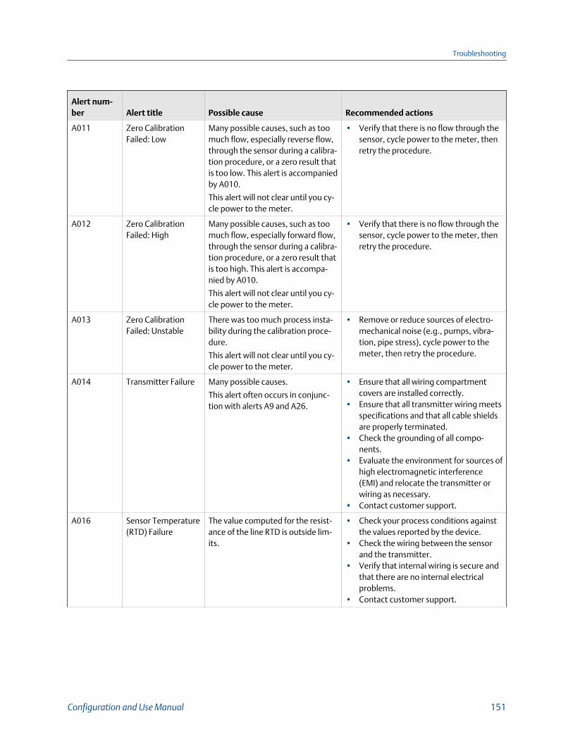
Alert num-ber Alert title Possible cause Recommended actions
A011 Zero CalibrationFailed: Low
Many possible causes, such as toomuch flow, especially reverse flow,through the sensor during a calibra-tion procedure, or a zero result thatis too low. This alert is accompaniedby A010.
This alert will not clear until you cy-cle power to the meter.
• Verify that there is no flow through thesensor, cycle power to the meter, thenretry the procedure.
A012 Zero CalibrationFailed: High
Many possible causes, such as toomuch flow, especially forward flow,through the sensor during a calibra-tion procedure, or a zero result thatis too high. This alert is accompa-nied by A010.
This alert will not clear until you cy-cle power to the meter.
• Verify that there is no flow through thesensor, cycle power to the meter, thenretry the procedure.
A013 Zero CalibrationFailed: Unstable
There was too much process insta-bility during the calibration proce-dure.
This alert will not clear until you cy-cle power to the meter.
• Remove or reduce sources of electro-mechanical noise (e.g., pumps, vibra-tion, pipe stress), cycle power to themeter, then retry the procedure.
A014 Transmitter Failure Many possible causes.
This alert often occurs in conjunc-tion with alerts A9 and A26.
• Ensure that all wiring compartmentcovers are installed correctly.
• Ensure that all transmitter wiring meetsspecifications and that all cable shieldsare properly terminated.
• Check the grounding of all compo-nents.
• Evaluate the environment for sources ofhigh electromagnetic interference(EMI) and relocate the transmitter orwiring as necessary.
• Contact customer support.
A016 Sensor Temperature(RTD) Failure
The value computed for the resist-ance of the line RTD is outside lim-its.
• Check your process conditions againstthe values reported by the device.
• Check the wiring between the sensorand the transmitter.
• Verify that internal wiring is secure andthat there are no internal electricalproblems.
• Contact customer support.
Troubleshooting
Configuration and Use Manual 151
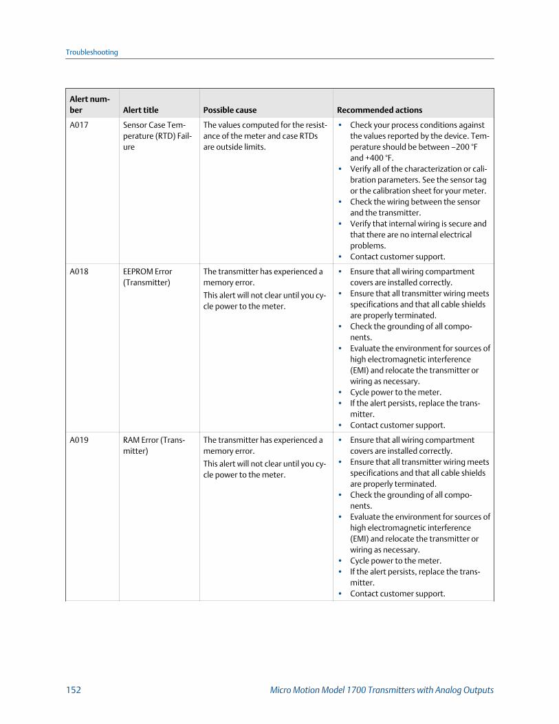
Alert num-ber Alert title Possible cause Recommended actions
A017 Sensor Case Tem-perature (RTD) Fail-ure
The values computed for the resist-ance of the meter and case RTDsare outside limits.
• Check your process conditions againstthe values reported by the device. Tem-perature should be between –200 °Fand +400 °F.
• Verify all of the characterization or cali-bration parameters. See the sensor tagor the calibration sheet for your meter.
• Check the wiring between the sensorand the transmitter.
• Verify that internal wiring is secure andthat there are no internal electricalproblems.
• Contact customer support.
A018 EEPROM Error(Transmitter)
The transmitter has experienced amemory error.
This alert will not clear until you cy-cle power to the meter.
• Ensure that all wiring compartmentcovers are installed correctly.
• Ensure that all transmitter wiring meetsspecifications and that all cable shieldsare properly terminated.
• Check the grounding of all compo-nents.
• Evaluate the environment for sources ofhigh electromagnetic interference(EMI) and relocate the transmitter orwiring as necessary.
• Cycle power to the meter.• If the alert persists, replace the trans-
mitter.• Contact customer support.
A019 RAM Error (Trans-mitter)
The transmitter has experienced amemory error.
This alert will not clear until you cy-cle power to the meter.
• Ensure that all wiring compartmentcovers are installed correctly.
• Ensure that all transmitter wiring meetsspecifications and that all cable shieldsare properly terminated.
• Check the grounding of all compo-nents.
• Evaluate the environment for sources ofhigh electromagnetic interference(EMI) and relocate the transmitter orwiring as necessary.
• Cycle power to the meter.• If the alert persists, replace the trans-
mitter.• Contact customer support.
Troubleshooting
152 Micro Motion Model 1700 Transmitters with Analog Outputs
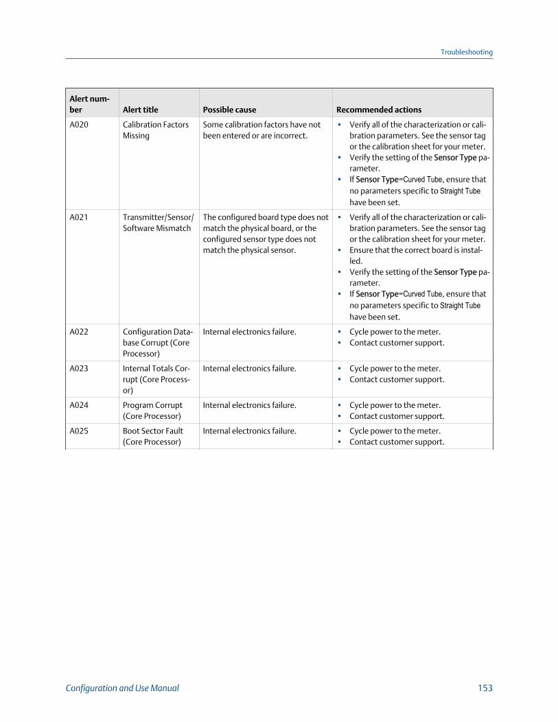
Alert num-ber Alert title Possible cause Recommended actions
A020 Calibration FactorsMissing
Some calibration factors have notbeen entered or are incorrect.
• Verify all of the characterization or cali-bration parameters. See the sensor tagor the calibration sheet for your meter.
• Verify the setting of the Sensor Type pa-rameter.
• If Sensor Type=Curved Tube, ensure thatno parameters specific to Straight Tubehave been set.
A021 Transmitter/Sensor/Software Mismatch
The configured board type does notmatch the physical board, or theconfigured sensor type does notmatch the physical sensor.
• Verify all of the characterization or cali-bration parameters. See the sensor tagor the calibration sheet for your meter.
• Ensure that the correct board is instal-led.
• Verify the setting of the Sensor Type pa-rameter.
• If Sensor Type=Curved Tube, ensure thatno parameters specific to Straight Tubehave been set.
A022 Configuration Data-base Corrupt (CoreProcessor)
Internal electronics failure. • Cycle power to the meter.• Contact customer support.
A023 Internal Totals Cor-rupt (Core Process-or)
Internal electronics failure. • Cycle power to the meter.• Contact customer support.
A024 Program Corrupt(Core Processor)
Internal electronics failure. • Cycle power to the meter.• Contact customer support.
A025 Boot Sector Fault(Core Processor)
Internal electronics failure. • Cycle power to the meter.• Contact customer support.
Troubleshooting
Configuration and Use Manual 153

Alert num-ber Alert title Possible cause Recommended actions
A026 Sensor/TransmitterCommunicationsFailure
The transmitter has lost communi-cation with the core processor.There may be a problem with thewiring or with either component.
This alert often occurs in conjunc-tion with alerts A9 and A14.
• Check the wiring between the sensorand the transmitter.
• Check for noise in the wiring or in thetransmitter environment.
• Verify that internal wiring is secure andthat there are no internal electricalproblems.
• Check the status LED on the core pro-cessor.
• Check the resistance across core pro-cessor terminals.
• If the alert persists:- Replace the core processor.- If that does not solve the problem,
restore the original core processorand replace the transmitter.
- If that does not solve the problem,replace both the transmitter andthe core processor.
A028 Core ProcessorWrite Failure
Internal electronics failure. • Cycle power to the meter.• Contact customer support.
A029 Internal ElectronicsFailure
This can indicate a loss of communi-cation between the transmitter andthe display module.
• Cycle power to the meter.• Replace the display module.• Contact customer support.
A030 Incorrect Board Type The loaded software is not compati-ble with the programmed boardtype.
• Contact customer support.
A031 Low Power The core processor or transmitter isnot receiving enough power.
This alert will not clear until you cy-cle power to the meter.
• Check the wiring between the transmit-ter and the core processor, then cyclepower to the meter.
• Check the wiring of the transmitter,then cycle power to the meter.
• Verify that the transmitter is receivingsufficient power.- If it is not, correct the problem and
cycle power to the meter.- If it is, this suggests that the trans-
mitter has an internal power issue.Replace the transmitter.
A032 Meter Verification inProgress: Outputs toFault
A meter verification test is in pro-gress, with outputs set to Fault.
• Allow the procedure to complete.
Troubleshooting
154 Micro Motion Model 1700 Transmitters with Analog Outputs

Alert num-ber Alert title Possible cause Recommended actions
A033 Insufficient PickoffSignal
The signal from the sensor pick-off(s) is insufficient. This suggeststhat the sensor tubes or vibratingelements are not vibrating. Thisalert often occurs in conjunctionwith Alert 102.
• Check for air in the flow tubes, tubesnot filled, foreign material in the tubes,coating in the tubes, or other processproblems.
• Check for foreign material in the proc-ess gas or fluid, coating, or other proc-ess problems.
• Check for fluid separation by monitor-ing the density value and comparingthe results against expected density val-ues.
• Ensure that the sensor orientation is ap-propriate for your application. Settlingfrom a two-phase or three-phase fluidcan cause this alert even if the flowtubes are full.
A035 Meter VerificationAborted
The meter verification test did notcomplete, possibly because of amanual abort.
• Verify that process conditions are sta-ble, then retry the test.
• Contact customer support.
A100 mA Output 1 Satura-ted
The calculated mA Output value isoutside the configured range.
• Check the settings of Upper Range Val-ue and Lower Range Value.
• Check process conditions. Actual condi-tions may be outside the normal condi-tions for which the output is config-ured.
• Check for air in the flow tubes, tubesnot filled, foreign material in the tubes,coating in the tubes, or other processproblems.
• Verify that the measurement units areconfigured correctly for your applica-tion.
• Purge the sensor tubes.
A101 mA Output 1 Fixed The HART address is set to a non-zero value, or the mA Output is con-figured to send a constant value.
• Check whether the output is in loop testmode. If it is, unfix the output.
• Exit mA Output trim, if applicable.• Check the HART address. If the HART
address is non-zero, you may need tochange the setting of mA Output Ac-tion.
• Check whether the output has been setto a constant value via digital communi-cation.
Troubleshooting
Configuration and Use Manual 155

Alert num-ber Alert title Possible cause Recommended actions
A102 Drive Overrange The drive power (current/voltage) isat its maximum.
• Check the drive gain and the pickoffvoltage.
• Check the wiring between the sensorand the transmitter.
• Verify that internal wiring is secure andthat there are no internal electricalproblems.
• Check for air in the flow tubes, tubesnot filled, foreign material in the tubes,coating in the tubes, or other processproblems.
• Check for fluid separation by monitor-ing the density value and comparingthe results against expected density val-ues.
• Ensure that the sensor orientation is ap-propriate for your application. Settlingfrom a two-phase or three-phase fluidcan cause this alert even if the flowtubes are full.
A103 Data Loss Possible(Totals and Invento-ries)
Totalizers are not properly saved.The device was unable to store thetotalizers during the last power-down, and must rely on the savedtotals. The saved totals can be asmuch as two hours out of date.
• Check the wiring between the transmit-ter and the core processor, then cyclepower to the meter.
• Verify that the transmitter is receivingsufficient power.- If it is not, correct the problem and
cycle power to the meter.- If it is, this suggests that the trans-
mitter has an internal power issue.Replace the transmitter.
A104 Calibration in Pro-gress
A calibration procedure is in proc-ess.
• Allow the procedure to complete.• For zero calibration, you may abort the
calibration, set Zero Time to a lower val-ue, and restart the calibration.
A105 Two-Phase Flow The line density is outside the user-defined two-phase flow limits.
• Check for two-phase flow.• Check the live density reading against
the upper and lower two-phase flowlimit settings.
A106 Burst Mode Enabled HART burst mode is enabled. • No action required.• If desired, you can set Alert Severity
Level to Ignore.
A107 Power Reset Occur-red
The transmitter has been restarted. • No action required.• If desired, you can set Alert Severity
Level to Ignore.
Troubleshooting
156 Micro Motion Model 1700 Transmitters with Analog Outputs
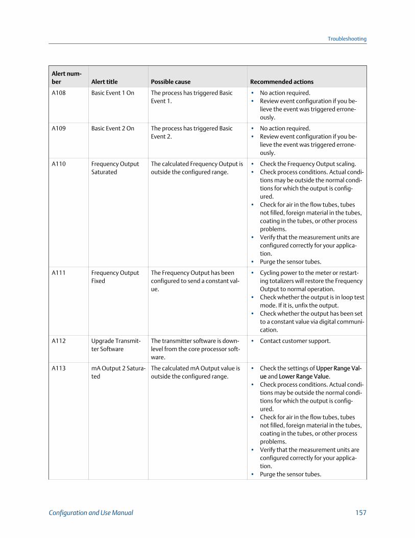
Alert num-ber Alert title Possible cause Recommended actions
A108 Basic Event 1 On The process has triggered BasicEvent 1.
• No action required.• Review event configuration if you be-
lieve the event was triggered errone-ously.
A109 Basic Event 2 On The process has triggered BasicEvent 2.
• No action required.• Review event configuration if you be-
lieve the event was triggered errone-ously.
A110 Frequency OutputSaturated
The calculated Frequency Output isoutside the configured range.
• Check the Frequency Output scaling.• Check process conditions. Actual condi-
tions may be outside the normal condi-tions for which the output is config-ured.
• Check for air in the flow tubes, tubesnot filled, foreign material in the tubes,coating in the tubes, or other processproblems.
• Verify that the measurement units areconfigured correctly for your applica-tion.
• Purge the sensor tubes.
A111 Frequency OutputFixed
The Frequency Output has beenconfigured to send a constant val-ue.
• Cycling power to the meter or restart-ing totalizers will restore the FrequencyOutput to normal operation.
• Check whether the output is in loop testmode. If it is, unfix the output.
• Check whether the output has been setto a constant value via digital communi-cation.
A112 Upgrade Transmit-ter Software
The transmitter software is down-level from the core processor soft-ware.
• Contact customer support.
A113 mA Output 2 Satura-ted
The calculated mA Output value isoutside the configured range.
• Check the settings of Upper Range Val-ue and Lower Range Value.
• Check process conditions. Actual condi-tions may be outside the normal condi-tions for which the output is config-ured.
• Check for air in the flow tubes, tubesnot filled, foreign material in the tubes,coating in the tubes, or other processproblems.
• Verify that the measurement units areconfigured correctly for your applica-tion.
• Purge the sensor tubes.
Troubleshooting
Configuration and Use Manual 157
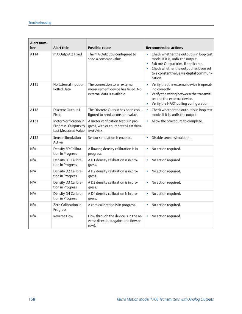
Alert num-ber Alert title Possible cause Recommended actions
A114 mA Output 2 Fixed The mA Output is configured tosend a constant value.
• Check whether the output is in loop testmode. If it is, unfix the output.
• Exit mA Output trim, if applicable.• Check whether the output has been set
to a constant value via digital communi-cation.
A115 No External Input orPolled Data
The connection to an externalmeasurement device has failed. Noexternal data is available.
• Verify that the external device is operat-ing correctly.
• Verify the wiring between the transmit-ter and the external device.
• Verify the HART polling configuration.
A118 Discrete Output 1Fixed
The Discrete Output has been con-figured to send a constant value.
• Check whether the output is in loop testmode. If it is, unfix the output.
A131 Meter Verification inProgress: Outputs toLast Measured Value
A meter verification test is in pro-gress, with outputs set to Last Meas-ured Value.
• Allow the procedure to complete.
A132 Sensor SimulationActive
Sensor simulation is enabled. • Disable sensor simulation.
N/A Density FD Calibra-tion in Progress
A flowing density calibration is inprogress.
• No action required.
N/A Density D1 Calibra-tion in Progress
A D1 density calibration is in pro-gress.
• No action required.
N/A Density D2 Calibra-tion in Progress
A D2 density calibration is in pro-gress.
• No action required.
N/A Density D3 Calibra-tion in Progress
A D3 density calibration is in pro-gress.
• No action required.
N/A Density D4 Calibra-tion in Progress
A D4 density calibration is in pro-gress.
• No action required.
N/A Zero Calibration inProgress
A zero calibration is in progress. • No action required.
N/A Reverse Flow Flow through the device is in the re-verse direction (against the flow ar-row).
• No action required.
Troubleshooting
158 Micro Motion Model 1700 Transmitters with Analog Outputs

10.3 Flow measurement problems
Problem Possible causes Recommended actions
Non-zero flow readingat no-flow conditionsor at zero offset
• Misaligned piping (especially in new instal-lations)
• Open or leaking valve• Incorrect sensor zero
• If the reading is not excessively high, re-view the live zero. You may need to restorethe factory zero.
• Check for open or leaking valves or seals.• Check for mounting stress on the sensor
(e.g., sensor being used to support piping,misaligned piping).
• Contact customer support.
Erratic non-zero flowrate at no-flow condi-tions
• Leaking valve or seal• Two-phase flow• Plugged or coated sensor tube• Incorrect sensor orientation• Wiring problem• Vibration in pipeline at rate close to sensor
tube frequency• Damping value too low• Mounting stress on sensor
• Verify that the sensor orientation is appro-priate for your application (refer to thesensor installation manual).
• Check the drive gain and the pickoff volt-age.
• If the wiring between the sensor and thetransmitter includes a 9-wire segment,verify that the 9-wire cable shields are cor-rectly grounded.
• Check the wiring between the sensor andthe transmitter.
• For sensors with a junction box, check formoisture in the junction box.
• Purge the sensor tubes.• Check for open or leaking valves or seals.• Check for sources of vibration.• Verify damping configuration.• Verify that the measurement units are con-
figured correctly for your application.• Check for two-phase flow.• Check for radio frequency interference.• Contact customer support.
Troubleshooting
Configuration and Use Manual 159

Problem Possible causes Recommended actions
Erratic non-zero flowrate when flow issteady
• Two-phase flow• Damping value too low• Plugged or coated sensor tube• Output wiring problem• Problem with receiving device• Wiring problem
• Verify that the sensor orientation is appro-priate for your application (refer to thesensor installation manual).
• Check the drive gain and the pickoff volt-age.
• If the wiring between the sensor and thetransmitter includes a 9-wire segment,verify that the 9-wire cable shields are cor-rectly grounded.
• Check for air entrainment, tube fouling,flashing, or tube damage.
• Check the wiring between the sensor andthe transmitter.
• For sensors with a junction box, check formoisture in the junction box.
• Purge the sensor tubes.• Check for open or leaking valves or seals.• Check for sources of vibration.• Verify damping configuration.• Verify that the measurement units are con-
figured correctly for your application.• Check for two-phase flow.• Check for radio frequency interference.• Contact customer support.
Inaccurate flow rateor batch total
• Wiring problem• Inappropriate measurement unit• Incorrect flow calibration factor• Incorrect meter factor• Incorrect density calibration factors• Incorrect grounding• Two-phase flow• Problem with receiving device• Incorrect sensor zero
• Check the wiring between the sensor andthe transmitter.
• Verify that the measurement units are con-figured correctly for your application.
• Verify all of the characterization or calibra-tion parameters. See the sensor tag or thecalibration sheet for your meter.
• Perform a bucket test to verify batch to-tals.
• Zero the meter.• Check the grounding of all components.• Check for two-phase flow.• Verify the receiving device, and the wiring
between the transmitter and the receivingdevice.
• Check sensor coil resistance and for shortsto case.
• Replace the core processor or transmitter.
Troubleshooting
160 Micro Motion Model 1700 Transmitters with Analog Outputs

10.4 Density measurement problems
Problem Possible causes Recommended actions
Inaccurate densityreading
• Problem with process fluid• Incorrect density calibration factors• Wiring problem• Incorrect grounding• Two-phase flow• Plugged or coated sensor tube• Incorrect sensor orientation• RTD failure• Physical characteristics of sensor have
changed
• Check your process conditions against thevalues reported by the device.
• Ensure that all of the calibration parame-ters have been entered correctly. See thesensor tag or the calibration sheet for yourmeter.
• Check the wiring between the sensor andthe transmitter.
• Check the grounding of all components.• Verify all of the characterization or calibra-
tion parameters. See the sensor tag or thecalibration sheet for your meter.
• Check for two-phase flow.• If two sensors with similar frequency are
too near each other, separate them.• Purge the sensor tubes.
Unusually high densi-ty reading
• Plugged or coated sensor tube• Incorrect density calibration factors• Incorrect temperature measurement• RTD problem• In high-frequency meters, this can indicate
erosion or corrosion• In low-frequency meters, this can indicate
tube fouling
• Ensure that all of the calibration parame-ters have been entered correctly. See thesensor tag or the calibration sheet for yourmeter.
• Verify all of the characterization or calibra-tion parameters. See the sensor tag or thecalibration sheet for your meter.
• Purge the sensor tubes.• Check for coating in the flow tubes.
Unusually low densityreading
• Two-phase flow• Ensure that all of the calibration parame-
ters have been entered correctly. See thesensor tag or the calibration sheet for yourmeter.
• In low-frequency meters, this can indicateerosion or corrosion
• Check your process conditions against thevalues reported by the device.
• Check for two-phase flow.• Verify all of the characterization or calibra-
tion parameters. See the sensor tag or thecalibration sheet for your meter.
• Check the wiring between the sensor andthe transmitter.
• Check for tube erosion, especially if theprocess fluid is abrasive.
Troubleshooting
Configuration and Use Manual 161
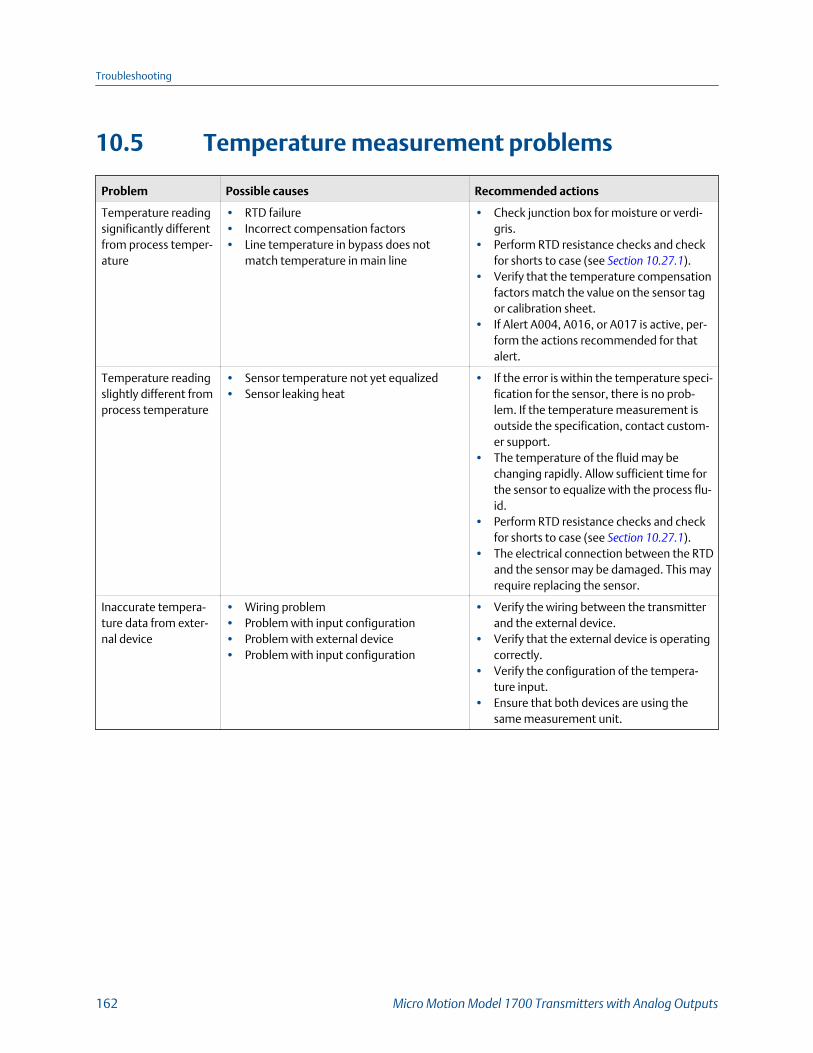
10.5 Temperature measurement problems
Problem Possible causes Recommended actions
Temperature readingsignificantly differentfrom process temper-ature
• RTD failure• Incorrect compensation factors• Line temperature in bypass does not
match temperature in main line
• Check junction box for moisture or verdi-gris.
• Perform RTD resistance checks and checkfor shorts to case (see Section 10.27.1).
• Verify that the temperature compensationfactors match the value on the sensor tagor calibration sheet.
• If Alert A004, A016, or A017 is active, per-form the actions recommended for thatalert.
Temperature readingslightly different fromprocess temperature
• Sensor temperature not yet equalized• Sensor leaking heat
• If the error is within the temperature speci-fication for the sensor, there is no prob-lem. If the temperature measurement isoutside the specification, contact custom-er support.
• The temperature of the fluid may bechanging rapidly. Allow sufficient time forthe sensor to equalize with the process flu-id.
• Perform RTD resistance checks and checkfor shorts to case (see Section 10.27.1).
• The electrical connection between the RTDand the sensor may be damaged. This mayrequire replacing the sensor.
Inaccurate tempera-ture data from exter-nal device
• Wiring problem• Problem with input configuration• Problem with external device• Problem with input configuration
• Verify the wiring between the transmitterand the external device.
• Verify that the external device is operatingcorrectly.
• Verify the configuration of the tempera-ture input.
• Ensure that both devices are using thesame measurement unit.
Troubleshooting
162 Micro Motion Model 1700 Transmitters with Analog Outputs

10.6 Milliamp output problems
Milliamp output problems and recommended actionsTable 10-2:
Problem Possible causes Recommended actions
No mA Output • Wiring problem• Circuit failure• Channel not configured for desired output
• Check the power supply and power supplywiring.
• Verify the output wiring.• Check the Fault Action settings.• Contact customer support.
Loop test failed • Power supply problem• Wiring problem• Circuit failure• Channel not configured for desired output• Incorrect internal/external power configu-
ration
• Check the power supply and power supplywiring.
• Verify the output wiring.• Check the Fault Action settings.• Verify channel configuration for the affec-
ted mA Output.• Contact customer support.
mA Output below4 mA
• Open in wiring• Bad output circuit• Process condition below LRV• LRV and URV are not set correctly• Fault condition if Fault Action is set to Inter-
nal Zero or Downscale• Bad mA receiving device
• Check your process conditions against thevalues reported by the device.
• Verify the receiving device, and the wiringbetween the transmitter and the receivingdevice.
• Check the settings of Upper Range Valueand Lower Range Value.
• Check the Fault Action settings.
Constant mA Output • Incorrect process variable assigned to theoutput
• Fault condition exists• Non-zero HART address (mA Output 1)• Output is configured for loop test mode• Zero calibration failure• Output is configured for a range that is far
in excess of intended range. Reconfigureoutput.
• The process condition is below cutoff.
• Verify the output variable assignments.• View and resolve any existing alert condi-
tions.• Check the HART address. If the HART ad-
dress is non-zero, you may need to changethe setting of mA Output Action.
• Check to see if a loop test is in process (theoutput is fixed).
• Check HART burst mode configuration.• If related to a zero calibration failure, cycle
power to the meter and retry the zeroingprocedure.
• Process condition is below cutoff. Checkand adjust the cutoff setting.
mA Output consis-tently out of range
• Incorrect process variable or units assignedto output
• Fault condition if Fault Action is set to Up-scale or Downscale
• LRV and URV are not set correctly
• Verify the output variable assignments.• Verify the measurement units configured
for the output.• Check the Fault Action settings.• Check the settings of Upper Range Value
and Lower Range Value.• Check the mA Output trim.
Troubleshooting
Configuration and Use Manual 163

Milliamp output problems and recommended actions (continued)Table 10-2:
Problem Possible causes Recommended actions
Consistently incorrectmA measurement
• Loop problem• Output not trimmed correctly• Incorrect measurement unit configured for
process variable• Incorrect process variable configured• LRV and URV are not set correctly
• Check the mA Output trim.• Verify that the measurement units are con-
figured correctly for your application.• Verify the process variable assigned to the
mA Output.• Check the settings of Upper Range Value
and Lower Range Value.
mA Output correct atlower current, but in-correct at higher cur-rent
• mA loop resistance may be set too high • Verify that the mA Output load resistanceis below the maximum supported load(see the installation manual for your trans-mitter).
10.7 Frequency Output problems
Frequency Output problems and recommended actionsTable 10-3:
Problem Possible causes Recommended actions
No Frequency Output • Stopped totalizer• Process condition below cutoff• Fault condition if Fault Action is set to Inter-
nal Zero or Downscale• Two-phase flow• Flow in reverse direction from configured
flow direction parameter• Bad frequency receiving device• Output level not compatible with receiving
device• Bad output circuit• Incorrect internal/external power configu-
ration• Wiring problem
• Verify that the process conditions are be-low the low-flow cutoff. Reconfigure thelow-flow cutoff if necessary.
• Check the Fault Action settings.• Verify that the totalizers are not stopped.
A stopped totalizer will cause the Frequen-cy Output to be locked.
• Check for two-phase flow.• Check flow direction.• Verify the receiving device, and the wiring
between the transmitter and the receivingdevice.
• Verify that the channel is wired and config-ured as a Frequency Output.
• Perform a loop test.
Consistently incorrectfrequency measure-ment
• Output not scaled correctly• Incorrect measurement unit configured for
process variable
• Check the Frequency Output scaling.• Verify that the measurement units are con-
figured correctly for your application.
Erratic FrequencyOutput
• Radio frequency interference (RFI) fromenvironment
• Check for radio frequency interference.
Troubleshooting
164 Micro Motion Model 1700 Transmitters with Analog Outputs

10.8 Using sensor simulation for troubleshootingWhen sensor simulation is enabled, the transmitter reports user-specified values for basicprocess variables. This allows you to reproduce various process conditions or to test thesystem.
You can use sensor simulation to help distinguish between legitimate process noise andexternally caused variation. For example, consider a receiving device that reports anunexpectedly erratic density value. If sensor simulation is enabled and the observeddensity value does not match the simulated value, the source of the problem is likely to besomewhere between the transmitter and the receiving device.
Sensor simulation requires an Enhanced Core and a communication device.
ImportantWhen sensor simulation is active, the simulated value is used in all transmitter outputs andcalculations, including totals and inventories, volume flow calculations, and concentrationcalculations. Disable all automatic functions related to the transmitter outputs and place the loop inmanual operation. Do not enable simulation mode unless your application can tolerate these effects,and be sure to disable simulation mode when you have finished testing.
10.9 Check power supply wiringIf the power supply wiring is damaged or improperly connected, the transmitter may notreceive enough power to operate properly.
Prerequisites
• You will need the installation manual for your transmitter.
• When using DC power, a minimum of 1.5 amps of startup current is required.
Procedure
1. Use a voltmeter to test the voltage at the transmitter’s power supply terminals.
• If the voltage is within the specified range, you do not have a power supplyproblem.
• If the voltage is low, ensure that the power supply is adequate at the source, thepower cable is sized correctly, there is no damage to the power cable, and anappropriate fuse is installed.
• If there is no power, continue with this procedure.
2. Before inspecting the power supply wiring, disconnect the power source.
CAUTION!
If the transmitter is in a hazardous area, wait five minutes after disconnecting thepower.
3. Ensure that the terminals, wires, and wiring compartment are clean and dry.
Troubleshooting
Configuration and Use Manual 165
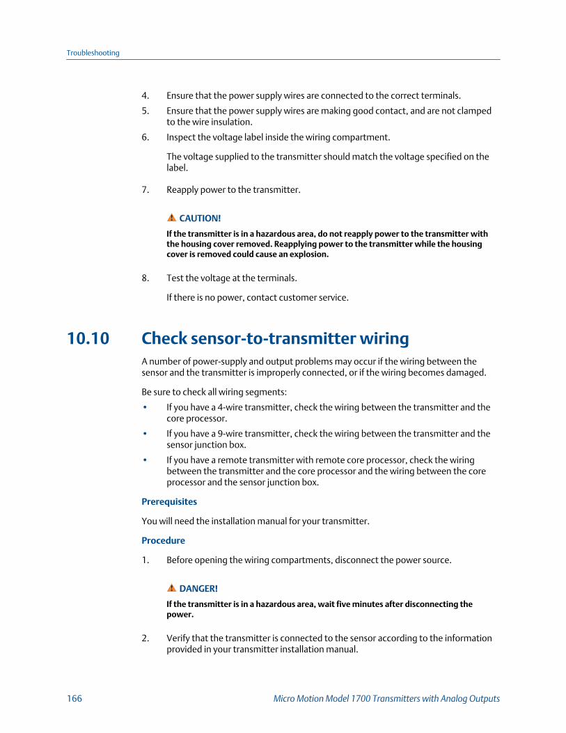
4. Ensure that the power supply wires are connected to the correct terminals.
5. Ensure that the power supply wires are making good contact, and are not clampedto the wire insulation.
6. Inspect the voltage label inside the wiring compartment.
The voltage supplied to the transmitter should match the voltage specified on thelabel.
7. Reapply power to the transmitter.
CAUTION!
If the transmitter is in a hazardous area, do not reapply power to the transmitter withthe housing cover removed. Reapplying power to the transmitter while the housingcover is removed could cause an explosion.
8. Test the voltage at the terminals.
If there is no power, contact customer service.
10.10 Check sensor-to-transmitter wiringA number of power-supply and output problems may occur if the wiring between thesensor and the transmitter is improperly connected, or if the wiring becomes damaged.
Be sure to check all wiring segments:
• If you have a 4-wire transmitter, check the wiring between the transmitter and thecore processor.
• If you have a 9-wire transmitter, check the wiring between the transmitter and thesensor junction box.
• If you have a remote transmitter with remote core processor, check the wiringbetween the transmitter and the core processor and the wiring between the coreprocessor and the sensor junction box.
Prerequisites
You will need the installation manual for your transmitter.
Procedure
1. Before opening the wiring compartments, disconnect the power source.
DANGER!
If the transmitter is in a hazardous area, wait five minutes after disconnecting thepower.
2. Verify that the transmitter is connected to the sensor according to the informationprovided in your transmitter installation manual.
Troubleshooting
166 Micro Motion Model 1700 Transmitters with Analog Outputs
3. Verify that the wires are making good contact with the terminals.
4. Check the continuity of all wires from the transmitter to the sensor.
10.11 Check groundingA sensor and the transmitter must be grounded. If the core processor is installed as part ofthe transmitter or the sensor, it is grounded automatically. If the core processor is installedseparately, it must be grounded separately.
Prerequisites
You will need an:
• Installation manual for your sensor
• Installation manual for your transmitter (remote-mount installations only)
Procedure
Refer to the sensor and transmitter installation manuals for grounding requirements andinstructions.
10.12 Perform loop testsA loop test is a way to verify that the transmitter and the remote device arecommunicating properly. A loop test also helps you know whether you need to trim mAOutputs.
Prerequisites
• Follow appropriate procedures to ensure that loop testing will not interfere withexisting measurement and control loops.
10.12.1 Perform loop tests using the displayPrerequisites
Before performing a loop test, configure the channels for the transmitter inputs andoutputs that will be used in your application.
Follow appropriate procedures to ensure that loop testing will not interfere with existingmeasurement and control loops.
Procedure
1. Test the mA Output(s).
a. Choose and select a low value, e.g., 4 mA.
Dots traverse the display while the output is fixed.
Troubleshooting
Configuration and Use Manual 167
b. Read the mA current at the receiving device and compare it to the transmitteroutput.
The readings do not need to match exactly. If the values are slightly different,you can correct the discrepancy by trimming the output.
c. At the transmitter, activate Select.
d. Scroll to and select a high value, e.g., 20 mA.
Dots traverse the display while the output is fixed.
e. Read the mA current at the receiving device and compare it to the transmitteroutput.
The readings do not need to match exactly. If the values are slightly different,you can correct the discrepancy by trimming the output.
f. At the transmitter, activate Select.
2. Test the Frequency Output(s).
a. Choose OFFLINE MAINT > SIM > FO SIM, and select the Frequency Output value.
The Frequency Output can be set to 1, 10, or 15 kHz.
NoteIf the Weights & Measures application with NTEP approval is enabled on the transmitter, itis not possible to perform a loop test of the Frequency Output, even when the transmitteris unsecured.
Dots traverse the display while the output is fixed.
b. Read the frequency signal at the receiving device and compare it to thetransmitter output.
c. At the transmitter, activate Select.
3. Test the Discrete Output(s).
a. Choose OFFLINE MAINT > SIM > DO SIM, and select SET ON.
Dots traverse the display while the output is fixed.
b. Verify the signal at the receiving device.
c. At the transmitter, activate Select.
d. Scroll to and select SET OFF.
e. Verify the signal at the receiving device.
f. At the transmitter, activate Select.
Troubleshooting
168 Micro Motion Model 1700 Transmitters with Analog Outputs

Postrequisites
• If the mA Output readings are within 20 microamps of the expected values, you cancorrect this discrepancy by trimming the output.
• If the discrepancy between the mA Output readings is greater than 20 microamps,or if at any step the reading was faulty, verify the wiring between the transmitterand the remote device, and try again.
10.12.2 Perform loop tests using ProLink IIIPrerequisites
Before performing a loop test, configure the channels for the transmitter inputs andoutputs that will be used in your application.
Follow appropriate procedures to ensure that loop testing will not interfere with existingmeasurement and control loops.
Procedure
1. Test the mA Output(s).
a. Choose Device Tools > Diagnostics > Testing > mA Output Test.
b. Enter 4 in Fix to:.
c. Click Fix mA.
d. Read the mA current at the receiving device and compare it to the transmitteroutput.
The readings do not need to match exactly. If the values are slightly different,you can correct the discrepancy by trimming the output.
e. Click UnFix mA.
f. Enter 20 in Fix to:.
g. Click Fix mA.
h. Read the mA current at the receiving device and compare it to the transmitteroutput.
The readings do not need to match exactly. If the values are slightly different,you can correct the discrepancy by trimming the output.
i. Click UnFix mA.
2. Test the Frequency Output(s).
a. Choose Device Tools > Diagnostics > Testing > Frequency Output Test.
b. Enter the Frequency Output value in Fix to.
c. Click Fix FO.
d. Read the frequency signal at the receiving device and compare it to thetransmitter output.
Troubleshooting
Configuration and Use Manual 169

e. Click UnFix FO.
3. Test the Discrete Output(s).
a. Choose Device Tools > Diagnostics > Testing > Discrete Output Test.
b. Set Fix To: to ON.
c. Verify the signal at the receiving device.
d. Set Fix To: to OFF.
e. Verify the signal at the receiving device.
f. Click UnFix.
Postrequisites
• If the mA Output readings are within 20 microamps of the expected values, you cancorrect this discrepancy by trimming the output.
• If the discrepancy between the mA Output readings is greater than 20 microamps,or if at any step the reading was faulty, verify the wiring between the transmitterand the remote device, and try again.
10.12.3 Perform loop tests using the Field CommunicatorPrerequisites
Before performing a loop test, configure the channels for the transmitter inputs andoutputs that will be used in your application.
Follow appropriate procedures to ensure that loop testing will not interfere with existingmeasurement and control loops.
Procedure
1. Test the mA Output(s).
a. Choose Service Tools > Simulate > Simulate Outputs > mA Output Loop Test andselect 4 mA.
b. Read the mA current at the receiving device and compare it to the transmitteroutput.
The readings do not need to match exactly. If the values are slightly different,you can correct the discrepancy by trimming the output.
c. Press OK.
d. Select 20 mA.
e. Read the mA current at the receiving device and compare it to the transmitteroutput.
The readings do not need to match exactly. If the values are slightly different,you can correct the discrepancy by trimming the output.
f. Press OK.
Troubleshooting
170 Micro Motion Model 1700 Transmitters with Analog Outputs

g. Choose End.
2. Test the Frequency Output(s).
NoteIf the Weights & Measures application with NTEP approval is enabled on the transmitter, it isnot possible to perform a loop test of the Frequency Output, even when the transmitter isunsecured.
a. Press Service Tools > Simulate > Simulate Outputs > Frequency Output Test, andchoose the Frequency Output level.
b. Read the frequency signal at the receiving device and compare it to thetransmitter output.
c. Choose End.
3. Test the Discrete Output(s).
a. Press Service Tools > Simulate > Simulate Outputs > Discrete Output Test.
b. Choose Off.
c. Verify the signal at the receiving device.
d. Press OK.
e. Choose On.
f. Verify the signal at the receiving device.
g. Press OK.
h. Choose End.
Postrequisites
• If the mA Output readings are within 20 microamps of the expected values, you cancorrect this discrepancy by trimming the output.
• If the discrepancy between the mA Output readings is greater than 20 microamps,or if at any step the reading was faulty, verify the wiring between the transmitterand the remote device, and try again.
10.13 Check the HART communication loopIf you cannot establish or maintain HART communications, the HART loop may be wiredincorrectly.
Prerequisites
You will need:
• A copy of your transmitter installation manual
• A 250–600 Ω resistor
• A Field Communicator
Troubleshooting
Configuration and Use Manual 171
• Optional: the HART Application Guide, available at www.hartcomm.org
Procedure
1. Verify that the loop wires are connected as shown in the wiring diagrams in thetransmitter installation manual.
If your HART network is more complex than the wiring diagrams in the transmitterinstallation manual, contact either customer service or the HART CommunicationFoundation.
2. Disconnect the primary mA Output wiring from the transmitter.
3. Install a 250–600 Ω resistor across the transmitter’s primary mA Output terminals.
4. Check the voltage drop across the resistor (4–20 mA = 1–5 VDC for a 250 Ωresistor).
If voltage drop is less than 1 VDC, add resistance to achieve a voltage drop of greaterthan 1 VDC .
5. Connect a Field Communicator directly across the resistor and attempt tocommunicate (poll).
If communication with the transmitter cannot be established, the transmitter mayneed service. Contact customer service.
10.14 Check HART Address and mA Output ActionIf the transmitter is producing a fixed current from the mA Output, the mA Output Actionparameter may be set incorrectly.
When the mA Output Action parameter is set to Fixed, the mA Output produces a fixedvalue, and does not report process data or implement its fault action.
When HART Address is changed, some configuration tools will automatically change mAOutput Action.
TipAlways verify mA Output Action after setting or changing HART Address.
Procedure
1. Set HART Address as appropriate for your HART network.
The default address is 0. This is the recommended value unless the transmitter is in amultidrop network.
2. Set mA Output Action to Live.
Troubleshooting
172 Micro Motion Model 1700 Transmitters with Analog Outputs
10.15 Check HART burst modeHART burst mode is normally disabled, and should be enabled only if a HART Triloop isbeing used.
1. Check to see if burst mode is enabled or disabled.
2. If burst mode is enabled, disable it.
10.16 Check the trimming of the mA OutputIf the trim values for the mA Output are inaccurate, the transmitter will under-compensateor over-compensate the output.
1. Trim the output, following the standard procedure.
2. If this does not correct the problem, contact customer support.
10.17 Check Lower Range Value and Upper RangeValueIf the process variable assigned to the mA Output falls below the configured Lower RangeValue (LRV) or rises above the configured Upper Range Value (URV), the meter will post asaturation alert (A100), then perform the configured fault action.
1. Record your current process conditions.
2. Check the configuration of the LRV and URV.
10.18 Check mA Output Fault ActionmA Output Fault Action controls the behavior of the mA Output if the transmitterencounters an internal fault condition. If the mA Output is reporting a constant valuebelow 4 mA or above 20 mA, the transmitter may be in a fault condition.
1. Check the status alerts for active fault conditions.
2. If there are active fault conditions, the transmitter is performing correctly. If youwant to change its behavior, consider the following options:
• Change the setting of mA Output Fault Action.
• For the relevant status alerts, change the setting of Alert Severity to Ignore.
RestrictionFor some status alerts, Alert Severity is not configurable.
3. If there are no active fault conditions, continue troubleshooting.
Troubleshooting
Configuration and Use Manual 173

10.19 Check for radio frequency interference (RFI)The transmitter's Frequency Output or Discrete Output can be affected by radio frequencyinterference (RFI). Possible sources of RFI include a source of radio emissions, or a largetransformer, pump, or motor that can generate a strong electromagnetic field. Severalmethods to reduce RFI are available. Use one or more of the following suggestions, asappropriate to your installation.
Procedure
• Use shielded cable between the output and the receiving device.
- Terminate the shielding at the receiving device. If this is impossible, terminatethe shielding at the cable gland or conduit fitting.
- Do not terminate the shielding inside the wiring compartment.
- 360-degree termination of shielding is unnecessary.
• Eliminate the RFI source.
• Move the transmitter.
10.20 Check Frequency Output Scaling MethodIf Frequency Output Scaling Method is set incorrectly, the Frequency Output may report anincorrect value.
1. Verify the configuration of the Frequency Output.
2. If you changed the setting of Frequency Output Scaling Method, check the settingsof all other Frequency Output parameters.
10.21 Check Frequency Output Fault ActionThe Frequency Output Fault Action controls the behavior of the Frequency Output if thetransmitter encounters an internal fault condition. If the Frequency Output is reporting aconstant value, the transmitter may be in a fault condition.
1. Check the status alerts for active fault conditions.
2. If there are active fault conditions, the transmitter is performing correctly. If youwant to change its behavior, consider the following options:
• Change the setting of Frequency Output Fault Action.
• For the relevant status alerts, change the setting of Alert Severity to Ignore.
RestrictionFor some status alerts, Alert Severity is not configurable.
3. If there are no active fault conditions, continue troubleshooting.
Troubleshooting
174 Micro Motion Model 1700 Transmitters with Analog Outputs

10.22 Check Flow DirectionIf Flow Direction is set inappropriately for your process, the transmitter may report flowdata that is not appropriate for your requirements.
The Flow Direction parameter interacts with actual flow direction to affect flow values,flow totals and inventories, and output behavior. For the simplest operation, actualprocess flow should match the flow arrow that is on the side of the sensor case.
Procedure
1. Verify the actual direction of process flow through the sensor.
2. Verify the configuration of Flow Direction.
10.23 Check the cutoffsIf the transmitter cutoffs are configured incorrectly, the transmitter may report zero flowwhen flow is present, or very small amounts of flow under no-flow conditions.
There are separate cutoff parameters for mass flow rate, volume flow rate, gas standardvolume flow rate (if applicable), and density. There is an independent cutoff for the mAOutput on your transmitter. The interaction between cutoffs sometimes producesunexpected results.
Procedure
Verify the configuration of all cutoffs.
TipFor typical applications, set Mass Flow Cutoff to 0.5% of the nominal flow rate of the attached sensor.See the sensor specifications for nominal flow rate data.
10.24 Check for two-phase flow (slug flow)Two-phase flow can cause rapid changes in the drive gain. This can cause a variety ofmeasurement issues.
1. Check for two-phase flow alerts (e.g., A105).
If the transmitter is not generating two-phase flow alerts, verify that two-phase flowlimits have been set. If limits are set, two-phase flow is not the source of yourproblem.
2. Check the process for cavitation, flashing, or leaks.
3. Monitor the density of your process fluid output under normal process conditions.
4. Check the settings of Two-Phase Flow Low Limit, Two-Phase Flow High Limit, andTwo-Phase Flow Timeout.
Troubleshooting
Configuration and Use Manual 175

TipYou can reduce the occurrence of two-phase flow alerts by setting Two-Phase Flow Low Limitto a lower value, Two-Phase Flow High Limit to a higher value, or Two-Phase Flow Timeout toa higher value. Micro Motion recommends leaving the Two-Phase Flow High Limit at thedefault value.
10.25 Check the drive gainExcessive or erratic drive gain may indicate any of a variety of process conditions or sensorproblems.
To know whether your drive gain is excessive or erratic, you must collect drive gain dataduring the problem condition and compare it to drive gain data from a period of normaloperation.
Excessive (saturated) drive gain
Possible causes and recommended actions for excessive (saturated)drive gainTable 10-4:
Possible cause Recommended actions
Bent sensor tube Check the pickoff voltages (see Section 10.26). If either of them are close tozero (but neither is zero), the sensor tubes may be bent. The sensor willneed to be replaced.
Cavitation or flash-ing; settling of two-phase or three-phasefluids
• Increase the inlet or back pressure at the sensor.• If a pump is located upstream from the sensor, increase the distance
between the pump and sensor.• The sensor may need to be reoriented or repositioned. Consult the in-
stallation manual for your sensor.
Cracked sensor tube Replace the sensor.
Core processoror module failure
Contact customer support.
Flow rate out ofrange
Ensure that the flow rate is within sensor limits.
Incorrect sensorcharacterization
Verify the characterization or calibration parameters.
Open drive or pickoffsensor coil
Contact customer support.
Over-pressurizedtubes
Contact customer support.
Plugged sensor tube Check the pickoff voltages (see Section 10.26). If either of them are close tozero (but neither is zero), plugged tubes may be the source of your prob-lem. Purge the tubes. In extreme cases, you may need to replace the sen-sor.
Sensor case fullof process fluid
Replace the sensor.
Troubleshooting
176 Micro Motion Model 1700 Transmitters with Analog Outputs
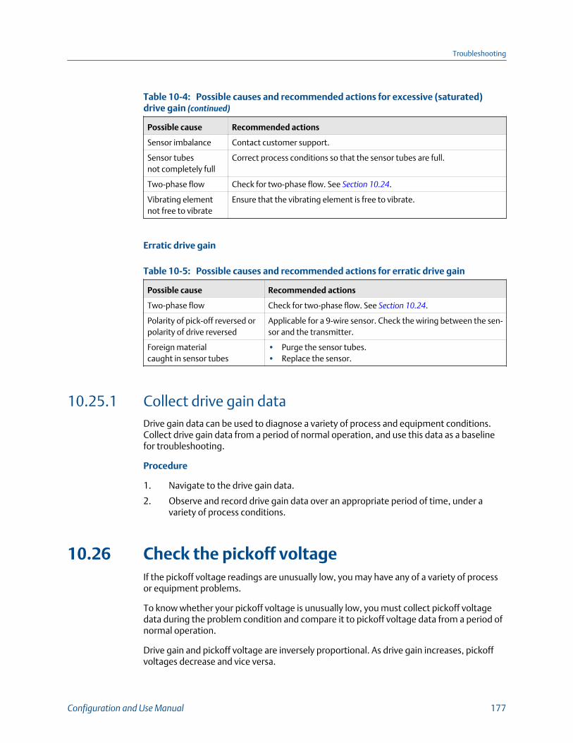
Possible causes and recommended actions for excessive (saturated)drive gain (continued)Table 10-4:
Possible cause Recommended actions
Sensor imbalance Contact customer support.
Sensor tubesnot completely full
Correct process conditions so that the sensor tubes are full.
Two-phase flow Check for two-phase flow. See Section 10.24.
Vibrating elementnot free to vibrate
Ensure that the vibrating element is free to vibrate.
Erratic drive gain
Possible causes and recommended actions for erratic drive gainTable 10-5:
Possible cause Recommended actions
Two-phase flow Check for two-phase flow. See Section 10.24.
Polarity of pick-off reversed orpolarity of drive reversed
Applicable for a 9-wire sensor. Check the wiring between the sen-sor and the transmitter.
Foreign materialcaught in sensor tubes
• Purge the sensor tubes.• Replace the sensor.
10.25.1 Collect drive gain dataDrive gain data can be used to diagnose a variety of process and equipment conditions.Collect drive gain data from a period of normal operation, and use this data as a baselinefor troubleshooting.
Procedure
1. Navigate to the drive gain data.
2. Observe and record drive gain data over an appropriate period of time, under avariety of process conditions.
10.26 Check the pickoff voltageIf the pickoff voltage readings are unusually low, you may have any of a variety of processor equipment problems.
To know whether your pickoff voltage is unusually low, you must collect pickoff voltagedata during the problem condition and compare it to pickoff voltage data from a period ofnormal operation.
Drive gain and pickoff voltage are inversely proportional. As drive gain increases, pickoffvoltages decrease and vice versa.
Troubleshooting
Configuration and Use Manual 177

Possible causes and recommended actions for low pickoff voltageTable 10-6:
Possible cause Recommended actions
Cavitation or flashing; settlingof two-phase or three-phasefluids
• Increase the inlet or back pressure at the sensor. Increasingback pressure is recommended. Applying back pressure down-stream from the sensor can prevent flashing inside the sensortubes. That way, if the process fluid is going to flash, it will doso downstream from the sensor after it has been measured.
• If a pump is located upstream from the sensor, increase thedistance between the pump and sensor.
• The sensor may need to be reoriented or repositioned. Consultthe installation manual for your sensor.
Faulty wiring runs betweenthe sensor and transmitter
Verify wiring between sensor and transmitter.
Process flow rate beyond thelimits of the sensor
Verify that the process flow rate is not out of range of the sensor.
Two-phase flow Check for two-phase flow. See Section 10.24.
The vibrating element is notvibrating
• Check for plugging or deposition.• Ensure that the vibrating element is free to vibrate (no me-
chanical binding).• Verify wiring.• Test coils at sensor. See Section 10.27.1.
Moisture in the sensor elec-tronics
Eliminate the moisture in the sensor electronics.
The sensor is damaged, orsensor magnets may have be-come demagnetized
Replace the sensor.
10.26.1 Collect pickoff voltage dataPickoff voltage data can be used to diagnose a variety of process and equipmentconditions. Collect pickoff voltage data from a period of normal operation, and use thisdata as a baseline for troubleshooting.
Procedure
1. Navigate to the pickoff voltage data.
2. Observe and record data for both the left pickoff and the right pickoff, over anappropriate period of time, under a variety of process conditions.
10.27 Check for internal electrical problemsShorts between sensor terminals or between the sensor terminals and the sensor case cancause the sensor to stop working.
Troubleshooting
178 Micro Motion Model 1700 Transmitters with Analog Outputs
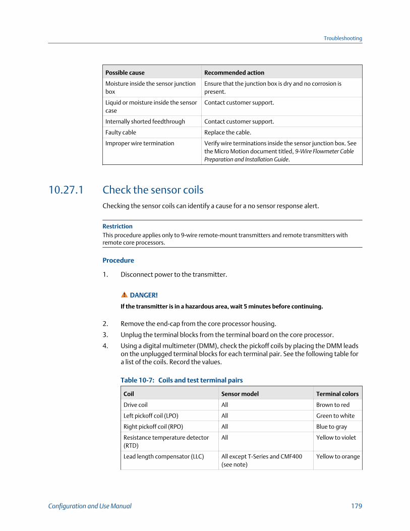
Possible cause Recommended action
Moisture inside the sensor junctionbox
Ensure that the junction box is dry and no corrosion ispresent.
Liquid or moisture inside the sensorcase
Contact customer support.
Internally shorted feedthrough Contact customer support.
Faulty cable Replace the cable.
Improper wire termination Verify wire terminations inside the sensor junction box. Seethe Micro Motion document titled, 9‐Wire Flowmeter CablePreparation and Installation Guide.
10.27.1 Check the sensor coilsChecking the sensor coils can identify a cause for a no sensor response alert.
RestrictionThis procedure applies only to 9-wire remote-mount transmitters and remote transmitters withremote core processors.
Procedure
1. Disconnect power to the transmitter.
DANGER!
If the transmitter is in a hazardous area, wait 5 minutes before continuing.
2. Remove the end-cap from the core processor housing.
3. Unplug the terminal blocks from the terminal board on the core processor.
4. Using a digital multimeter (DMM), check the pickoff coils by placing the DMM leadson the unplugged terminal blocks for each terminal pair. See the following table fora list of the coils. Record the values.
Coils and test terminal pairsTable 10-7:
Coil Sensor model Terminal colors
Drive coil All Brown to red
Left pickoff coil (LPO) All Green to white
Right pickoff coil (RPO) All Blue to gray
Resistance temperature detector(RTD)
All Yellow to violet
Lead length compensator (LLC) All except T-Series and CMF400(see note)
Yellow to orange
Troubleshooting
Configuration and Use Manual 179

Coils and test terminal pairs (continued)Table 10-7:
Coil Sensor model Terminal colors
Composite RTD All CMFSs, T-Series, H300, andF300
Yellow to orange
Fixed resistor (see note) CMFS007, CMFS010, CMFS015,CMF400, and F300
Yellow to orange
NoteThe F300/H300/CMF400 fixed resistor applies to only certain specific sensor releases. Contactcustomer support for more information.
There should be no open circuits, that is, no infinite resistance readings. The leftpickoff and right pickoff readings should be the same or very close (±5 Ω). If thereare any unusual readings, repeat the coil resistance tests at the sensor junction boxto eliminate the possibility of faulty cable. The readings for each coil pair shouldmatch at both ends.
5. Test the terminals in the sensor junction box for shorts to case.
Test results will be inconclusive with nonconductive process fluids such ashydrocarbons.
a. Leave the terminal blocks disconnected.
b. Remove the lid of the junction box.
c. Testing one terminal at a time, place a DMM lead on the terminal and the otherlead on the sensor case.
With the DMM set to its highest range, there should be infinite resistance oneach lead. If there is any resistance at all, there is a short to case.
6. Test the resistance of junction box terminal pairs.
a. Test the brown terminal against all other terminals except the red one.
b. Test the red terminal against all other terminals except the brown one.
c. Test the green terminal against all other terminals except the white one.
d. Test the white terminal against all other terminals except the green one.
e. Test the blue terminal against all other terminals except the gray one.
f. Test the gray terminal against all other terminals except the blue one.
g. Test the orange terminal against all other terminals except the yellow and violetones.
h. Test the yellow terminal against all other terminals except the orange and violetones.
i. Test the violet terminal against all other terminals except the yellow and orangeones.
Troubleshooting
180 Micro Motion Model 1700 Transmitters with Analog Outputs
There should be infinite resistance for each pair. If there is any resistance at all, thereis a short between terminals.
Postrequisites
To return to normal operation:
1. Plug the terminal blocks into the terminal board.
2. Replace the end-cap on the core processor housing.
3. Replace the lid on the sensor junction box.
ImportantWhen reassembling the meter components, be sure to grease all O-rings.
10.28 Check the core processor LEDThe core processor has an LED that indicates different meter conditions.
1. Maintain power to the transmitter.
2. If you have a 4-wire remote installation or a remote core processor with remotetransmitter installation:
a. Remove the core processor lid. The core processor is intrinsically safe and can beopened in all environments.
b. Check the state of the core processor LED.
3. If you have an integral installation:
a. Loosen the four cap screws that fasten the transmitter to the base.
Troubleshooting
Configuration and Use Manual 181

Integral installation componentsFigure 10-1:
A. TransmitterB. Transition ringC. 4 x cap screws (4 mm)D. BaseE. Core processor
b. Rotate the transmitter counter-clockwise so that the cap screws are in theunlocked position.
c. Gently lift the transmitter straight up, disengaging it from the cap screws.
ImportantDo not disconnect or damage the wires that connect the transmitter to the coreprocessor.
d. Check the state of the core processor LED.
4. If you have a 9-wire remote installation:
a. Remove the end-cap.
Troubleshooting
182 Micro Motion Model 1700 Transmitters with Analog Outputs
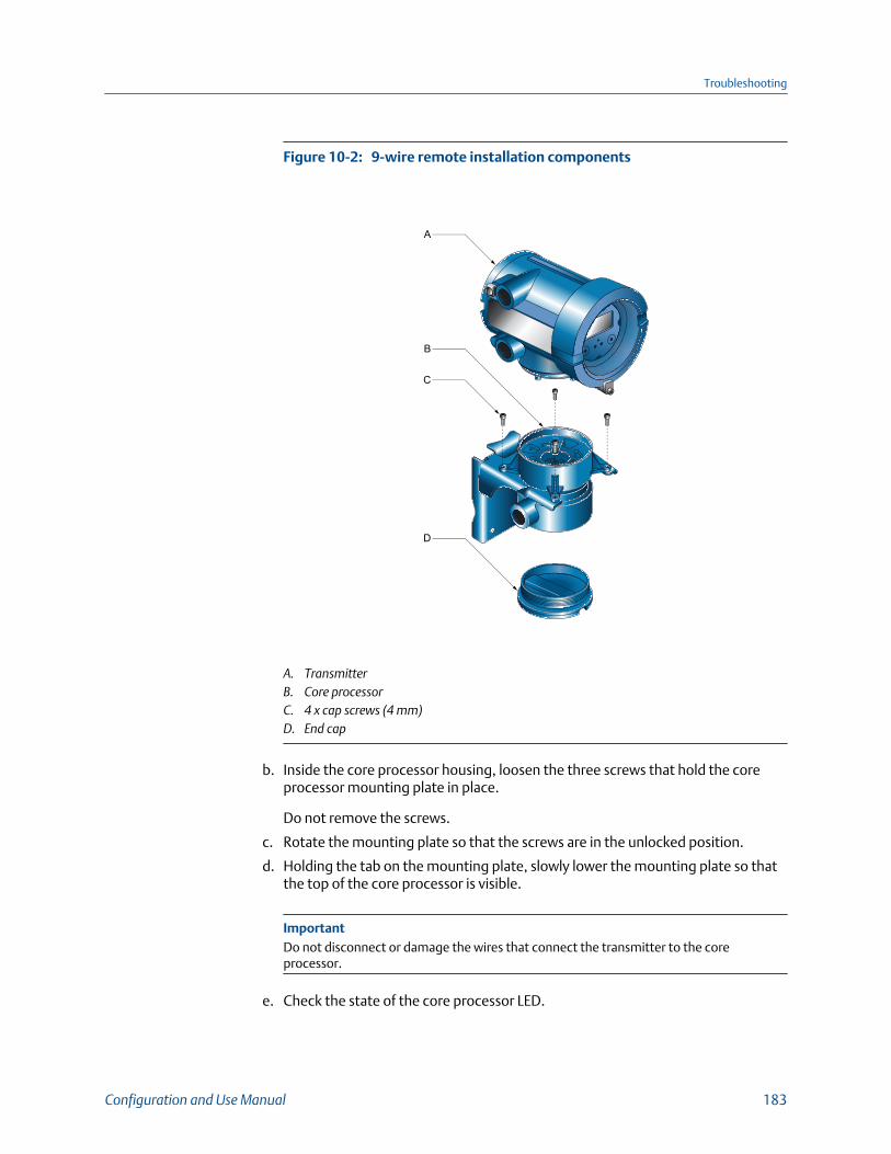
9-wire remote installation componentsFigure 10-2:
A
C
D
B
A. TransmitterB. Core processorC. 4 x cap screws (4 mm)D. End cap
b. Inside the core processor housing, loosen the three screws that hold the coreprocessor mounting plate in place.
Do not remove the screws.
c. Rotate the mounting plate so that the screws are in the unlocked position.
d. Holding the tab on the mounting plate, slowly lower the mounting plate so thatthe top of the core processor is visible.
ImportantDo not disconnect or damage the wires that connect the transmitter to the coreprocessor.
e. Check the state of the core processor LED.
Troubleshooting
Configuration and Use Manual 183

Postrequisites
To return to normal operation:
• For a 4-wire remote installation or a remote core processor with remote transmitterinstallation, replace the core processor lid.
• For an integral installation:
1. Without pinching or stretching the wires, lower the transmitter onto the base,inserting the cap screws into the slots.
2. Rotate the transmitter clockwise so that the cap screws are in the lockedposition.
3. Tighten the cap screws, torquing to 20 to 30 in-lbs (2.3 to 3.4 N-m.
• For a 9-wire remote installation:
1. Without pinching or stressing the wires, slide the mounting plate into place.
2. Rotate the mounting plate so that the screws are in the locked position.
3. Tighten the screws, torquing to 6 to 8 in-lbs (0.7 to 0.9 N-m.
4. Replace the end-cap.
ImportantWhen reassembling the meter components, be sure to grease all O-rings.
10.28.1 Core processor LED states
Standard core processor LED statesTable 10-8:
LED state Description Recommended actions
1 flash per second (ON 25%, OFF75%)
Normal operation No action required.
1 flash per second (ON 75%, OFF25%)
Slug flow (two-phase flow) See Section 10.24.
Solid ON Zero or calibration in progress No action required.
Core processor receiving be-tween 11.5 and 5 volts
Check power supply to transmitter.
3 rapid flashes, followed bypause
Sensor not recognized Check wiring between transmitter and sensor.
Improper configuration Check sensor characterization parameters.
Broken pin between sensor andcore processor
The meter requires factory service.
4 flashes per second Fault condition Check alert status.
Troubleshooting
184 Micro Motion Model 1700 Transmitters with Analog Outputs

Standard core processor LED states (continued)Table 10-8:
LED state Description Recommended actions
OFF Core processor receiving lessthan 5 volts
• Verify power supply wiring to core processor.• If transmitter status LED is lit, transmitter is re-
ceiving power. Check voltage across terminals1 (VDC+) and 2 (VDC–) in core processor. Ifreading is less than 1 VDC, verify power supplywiring to core processor. Wires may be switch-ed.
• If transmitter status LED is not lit, transmitteris not receiving power. Check power supply. Ifpower supply is operational, internal transmit-ter, display, or LED failure is possible – the me-ter may require factory service.
Core processor internal failure The meter requires factory service.
Enhanced core processor LED statesTable 10-9:
LED state Description Recommended action
Solid green Normal operation No action required.
Flashing yellow Zero in progress No action required.
Solid yellow Low-severity alert Check alert status.
Solid red High-severity alert Check alert status.
Flashing red (80% on, 20% off) Tubes not full • If alert A105 (slug flow) is active, refer to therecommended actions for that alert.
• If alert A033 (tubes not full) is active, verifyprocess. Check for air in the flow tubes, tubesnot filled, foreign material in tubes, or coatingin tubes.
Flashing red (50% on, 50% off) Electronics failed The meter requires factory service.
Flashing red (50% on, 50% off,skips every 4th)
Sensor failed The meter requires factory service.
OFF Core processor receiving lessthan 5 volts
• Verify power supply wiring to core processor.• If transmitter status LED is lit, transmitter is re-
ceiving power. Check voltage across terminals1 (VDC+) and 2 (VDC–) in core processor. Ifreading is less than 1 VDC, verify power supplywiring to core processor. Wires may be switch-ed.
• If transmitter status LED is not lit, transmitteris not receiving power. Check power supply. Ifpower supply is operational, internal transmit-ter, display, or LED failure is possible – the me-ter may require factory service.
Troubleshooting
Configuration and Use Manual 185

Enhanced core processor LED states (continued)Table 10-9:
LED state Description Recommended action
Core processor internal failure The meter requires factory service.
10.29 Perform a 700 core processor resistance test
NoteYou can perform a resistance test only on a 700 core processor.
Procedure
1. Power down the transmitter.
2. If you have a 4-wire remote installation or a remote core processor with remotetransmitter installation, remove the core processor lid.
3. If you have an integral installation:
a. Loosen the four cap screws that fasten the transmitter to the base.
A. TransmitterB. Transition ringC. 4 x cap screws (4 mm)D. BaseE. Core processor
b. Rotate the transmitter counter-clockwise so that the cap screws are in theunlocked position.
Troubleshooting
186 Micro Motion Model 1700 Transmitters with Analog Outputs
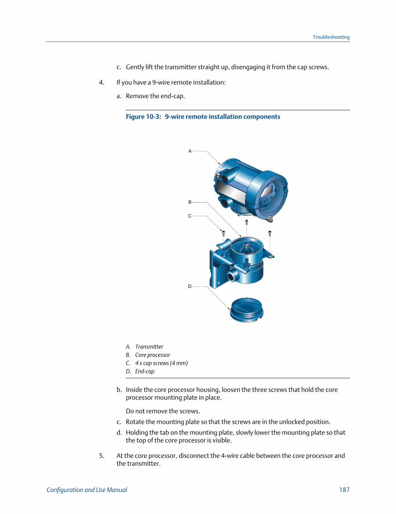
c. Gently lift the transmitter straight up, disengaging it from the cap screws.
4. If you have a 9-wire remote installation:
a. Remove the end-cap.
9-wire remote installation componentsFigure 10-3:
A
C
D
B
A. TransmitterB. Core processorC. 4 x cap screws (4 mm)D. End‐cap
b. Inside the core processor housing, loosen the three screws that hold the coreprocessor mounting plate in place.
Do not remove the screws.
c. Rotate the mounting plate so that the screws are in the unlocked position.
d. Holding the tab on the mounting plate, slowly lower the mounting plate so thatthe top of the core processor is visible.
5. At the core processor, disconnect the 4-wire cable between the core processor andthe transmitter.
Troubleshooting
Configuration and Use Manual 187
6. Measure the resistance between core processor terminal pairs 3–4, 2–3, and 2–4.
Terminal pair Function Expected resistance
3–4 RS-485/A and RS-485/B 40 kΩ to 50 kΩ
2–3 VDC– and RS-485/A 20 kΩ to 25 kΩ
2–4 VDC– and RS-485/B 20 kΩ to 25 kΩ
7. If any resistance measurements are lower than specified, the core processor maynot be able to communicate with a transmitter or a remote host. The meter mayneed factory service.
Postrequisites
To return to normal operation:
• For a 4-wire remote installation or a remote core processor with remote transmitterinstallation:
1. Reconnect the 4-wire cable between the core processor and the transmitter.
2. Replace the core processor lid.
3. Restore power to the transmitter.
• For an integral installation:
1. Reconnect the 4-wire cable between the core processor and the transmitter.
2. Without pinching or stretching the wires, lower the transmitter onto the base,inserting the cap screws into the slots.
3. Rotate the transmitter clockwise so that the cap screws are in the lockedposition.
4. Tighten the cap screws, torquing to 20 to 30 in-lbs (2.3 to 3.4 N-m.
5. Restore power to the transmitter.
• For a 9-wire remote installation:
1. Reconnect the 4-wire cable between the core processor and the transmitter.
2. Without pinching or stressing the wires, slide the mounting plate into place.
3. Rotate the mounting plate so that the screws are in the locked position.
4. Tighten the screws, torquing to 6 to 8 in-lbs (0.7 to 0.9 N-m.
5. Replace the end-cap.
6. Restore power to the transmitter.
ImportantWhen reassembling the meter components, be sure to grease all O-rings.
Troubleshooting
188 Micro Motion Model 1700 Transmitters with Analog Outputs
Appendix AUsing the transmitter display
Topics covered in this appendix:
• Components of the transmitter interface
• Use the optical switches
• Access and use the display menu system
• Display codes for process variables
• Codes and abbreviations used in display menus
A.1 Components of the transmitter interfaceThe transmitter interface includes the status LED, the display (LCD panel), and two opticalswitches.
Using the transmitter display
Configuration and Use Manual 189
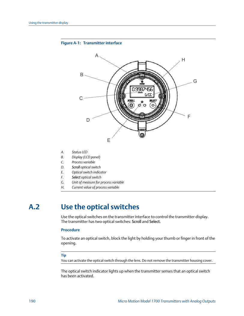
Transmitter interfaceFigure A-1:
A
B
C
D
E
F
G
H
A. Status LEDB. Display (LCD panel)C. Process variableD. Scroll optical switchE. Optical switch indicatorF. Select optical switchG. Unit of measure for process variableH. Current value of process variable
A.2 Use the optical switchesUse the optical switches on the transmitter interface to control the transmitter display.The transmitter has two optical switches: Scroll and Select.
Procedure
To activate an optical switch, block the light by holding your thumb or finger in front of theopening.
TipYou can activate the optical switch through the lens. Do not remove the transmitter housing cover.
The optical switch indicator lights up when the transmitter senses that an optical switchhas been activated.
Using the transmitter display
190 Micro Motion Model 1700 Transmitters with Analog Outputs
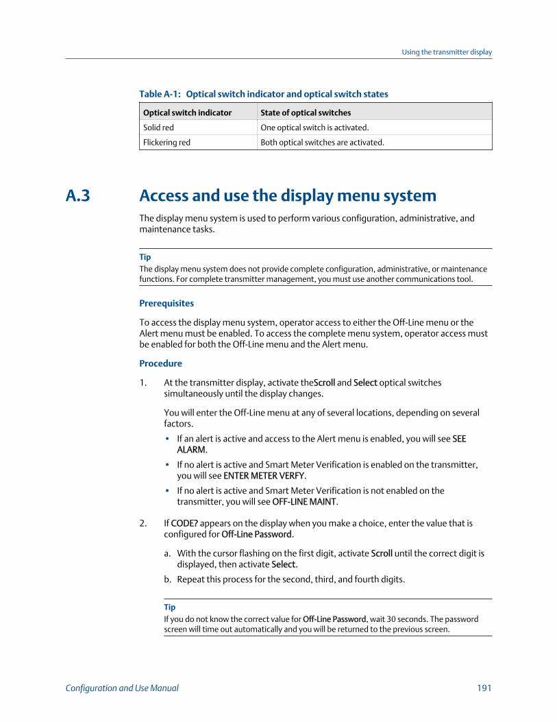
Optical switch indicator and optical switch statesTable A-1:
Optical switch indicator State of optical switches
Solid red One optical switch is activated.
Flickering red Both optical switches are activated.
A.3 Access and use the display menu systemThe display menu system is used to perform various configuration, administrative, andmaintenance tasks.
TipThe display menu system does not provide complete configuration, administrative, or maintenancefunctions. For complete transmitter management, you must use another communications tool.
Prerequisites
To access the display menu system, operator access to either the Off-Line menu or theAlert menu must be enabled. To access the complete menu system, operator access mustbe enabled for both the Off-Line menu and the Alert menu.
Procedure
1. At the transmitter display, activate theScroll and Select optical switchessimultaneously until the display changes.
You will enter the Off-Line menu at any of several locations, depending on severalfactors.
• If an alert is active and access to the Alert menu is enabled, you will see SEEALARM.
• If no alert is active and Smart Meter Verification is enabled on the transmitter,you will see ENTER METER VERFY.
• If no alert is active and Smart Meter Verification is not enabled on thetransmitter, you will see OFF-LINE MAINT.
2. If CODE? appears on the display when you make a choice, enter the value that isconfigured for Off-Line Password.
a. With the cursor flashing on the first digit, activate Scroll until the correct digit isdisplayed, then activate Select.
b. Repeat this process for the second, third, and fourth digits.
TipIf you do not know the correct value for Off-Line Password, wait 30 seconds. The passwordscreen will time out automatically and you will be returned to the previous screen.
Using the transmitter display
Configuration and Use Manual 191

3. Use the Scroll and Select optical switches to navigate to your destination in thedisplay menu system.
• Use Scroll to move through a list of options.
• Use Select to choose the current option.
4. If Scroll flashes on the display, activate the Scroll optical switch, then the Selectoptical switch, and then the Scroll optical switch again.
The display will prompt you through this sequence. The Scroll-Select-Scrollsequence is designed to guard against accidental activation of the off-line menu. It isnot designed as a security measure.
5. To exit a display menu and return to a higher-level menu:
• Activate Scroll until the EXIT option is displayed, then activate Select.
• If the EXIT option is not available, activate Scroll and Select simultaneously andhold until the screen returns to the previous display.
6. To exit the display menu system, you can use either of the following methods:
• Exit each menu separately, working your way back to the top of the menusystem.
• Wait until the display times out and returns to displaying process variable data.
A.3.1 Enter a floating-point value using the displayCertain configuration values (for example, Lower Range Value and Upper Range Value) areentered as floating-point values. The display supports both decimal notation andexponential notation for floating-point values.
The display allows you to enter a maximum of 8 characters, including the sign. The decimalpoint is not counted as a character. Exponential notation is used to enter values thatrequire more than 8 characters.
Enter a floating-point value using decimal notationDecimal notation allows you to enter values between –9999999 and 99999999. You canuse the decimal point to enter values with a precision of 0 through 4 (4 characters to theright of the decimal point).
Decimal values entered via the display must meet the following requirements:
• They can contain a maximum of 8 digits, or 7 digits plus a minus sign (−) to indicatea negative number.
• They can contain a decimal point. The decimal point does not count as a digit. Thedecimal point must be positioned so that the precision of the value does not exceed4.
When you first enter the configuration screen, the current configuration value is displayedin decimal notation, and the active character is flashing. If the value is positive, no sign isdisplayed. If the value is negative, a minus sign is displayed.
Using the transmitter display
192 Micro Motion Model 1700 Transmitters with Analog Outputs
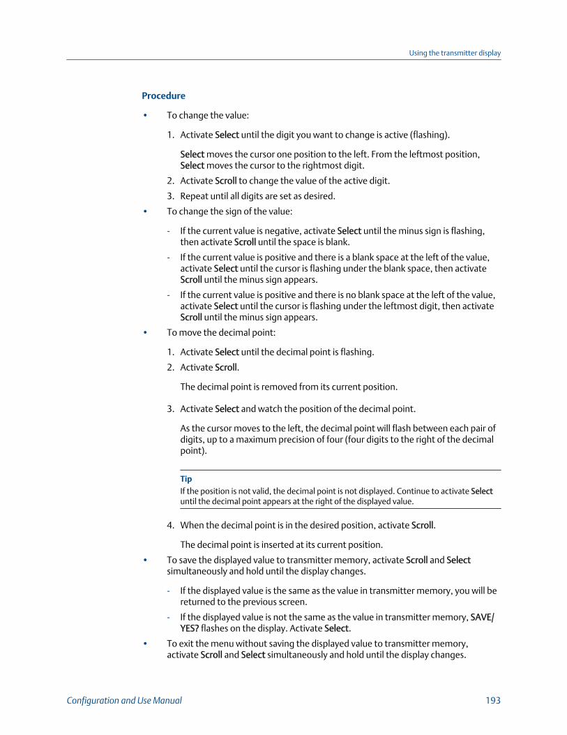
Procedure
• To change the value:
1. Activate Select until the digit you want to change is active (flashing).
Select moves the cursor one position to the left. From the leftmost position,Select moves the cursor to the rightmost digit.
2. Activate Scroll to change the value of the active digit.
3. Repeat until all digits are set as desired.
• To change the sign of the value:
- If the current value is negative, activate Select until the minus sign is flashing,then activate Scroll until the space is blank.
- If the current value is positive and there is a blank space at the left of the value,activate Select until the cursor is flashing under the blank space, then activateScroll until the minus sign appears.
- If the current value is positive and there is no blank space at the left of the value,activate Select until the cursor is flashing under the leftmost digit, then activateScroll until the minus sign appears.
• To move the decimal point:
1. Activate Select until the decimal point is flashing.
2. Activate Scroll.
The decimal point is removed from its current position.
3. Activate Select and watch the position of the decimal point.
As the cursor moves to the left, the decimal point will flash between each pair ofdigits, up to a maximum precision of four (four digits to the right of the decimalpoint).
TipIf the position is not valid, the decimal point is not displayed. Continue to activate Selectuntil the decimal point appears at the right of the displayed value.
4. When the decimal point is in the desired position, activate Scroll.
The decimal point is inserted at its current position.
• To save the displayed value to transmitter memory, activate Scroll and Selectsimultaneously and hold until the display changes.
- If the displayed value is the same as the value in transmitter memory, you will bereturned to the previous screen.
- If the displayed value is not the same as the value in transmitter memory, SAVE/YES? flashes on the display. Activate Select.
• To exit the menu without saving the displayed value to transmitter memory,activate Scroll and Select simultaneously and hold until the display changes.
Using the transmitter display
Configuration and Use Manual 193
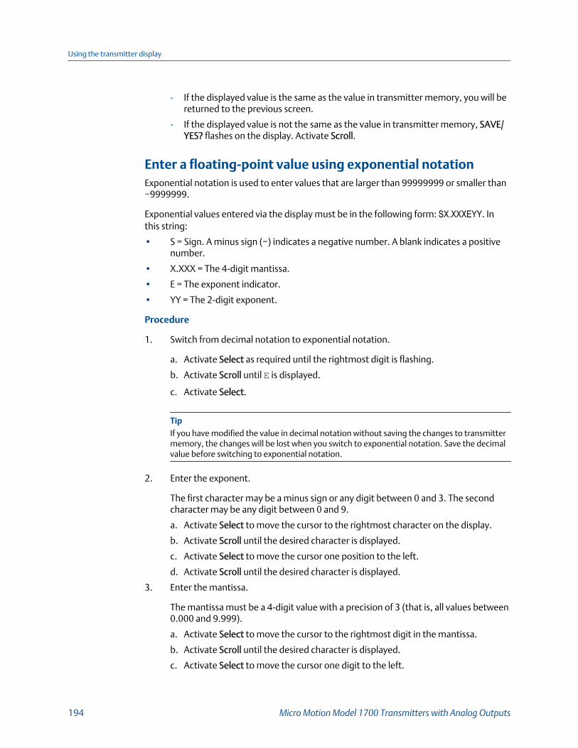
- If the displayed value is the same as the value in transmitter memory, you will bereturned to the previous screen.
- If the displayed value is not the same as the value in transmitter memory, SAVE/YES? flashes on the display. Activate Scroll.
Enter a floating-point value using exponential notationExponential notation is used to enter values that are larger than 99999999 or smaller than−9999999.
Exponential values entered via the display must be in the following form: SX.XXXEYY. Inthis string:
• S = Sign. A minus sign (−) indicates a negative number. A blank indicates a positivenumber.
• X.XXX = The 4-digit mantissa.
• E = The exponent indicator.
• YY = The 2-digit exponent.
Procedure
1. Switch from decimal notation to exponential notation.
a. Activate Select as required until the rightmost digit is flashing.
b. Activate Scroll until E is displayed.
c. Activate Select.
TipIf you have modified the value in decimal notation without saving the changes to transmittermemory, the changes will be lost when you switch to exponential notation. Save the decimalvalue before switching to exponential notation.
2. Enter the exponent.
The first character may be a minus sign or any digit between 0 and 3. The secondcharacter may be any digit between 0 and 9.
a. Activate Select to move the cursor to the rightmost character on the display.
b. Activate Scroll until the desired character is displayed.
c. Activate Select to move the cursor one position to the left.
d. Activate Scroll until the desired character is displayed.
3. Enter the mantissa.
The mantissa must be a 4-digit value with a precision of 3 (that is, all values between0.000 and 9.999).
a. Activate Select to move the cursor to the rightmost digit in the mantissa.
b. Activate Scroll until the desired character is displayed.
c. Activate Select to move the cursor one digit to the left.
Using the transmitter display
194 Micro Motion Model 1700 Transmitters with Analog Outputs

d. Activate Scroll until the desired character is displayed.
e. Activate Select to move the cursor one digit to the left.
f. Activate Scroll until the desired character is displayed.
g. Activate Select to move the cursor one digit to the left.
h. Activate Scroll until the desired character is displayed.
4. Enter the sign.
a. Activate Select to move the cursor one digit to the left.
b. Activate Scroll until the desired character is displayed.
For positive numbers, select a blank space.
5. To save the displayed value to transmitter memory, activate Scroll and Selectsimultaneously and hold until the display changes.
• If the displayed value is the same as the value in transmitter memory, you will bereturned to the previous screen.
• If the displayed value is not the same as the value in transmitter memory, SAVE/YES? flashes on the display. Activate Select.
6. Switch back from exponential notation to decimal notation.
a. Activate Select until the E is flashing.
b. Activate Select until d is displayed.
c. Activate Select.
A.4 Display codes for process variables
Display codes for process variablesTable A-2:
Code Definition Comment or reference
AVE_D Average density Petroleum measurement application only
AVE_T Average temperature Petroleum measurement application only
BRD_T Board temperature
CONC Concentration Concentration measurement application only
DRIVE% Drive gain
EXT_P External pressure
EXT_T External temperature
FVZ Field verification zero Weights & Measures application only
GSV F Gas standard volume flow
GSV I Gas standard volume inventory
GSV T Gas standard volume total
LPO_A Left pickoff amplitude
Using the transmitter display
Configuration and Use Manual 195
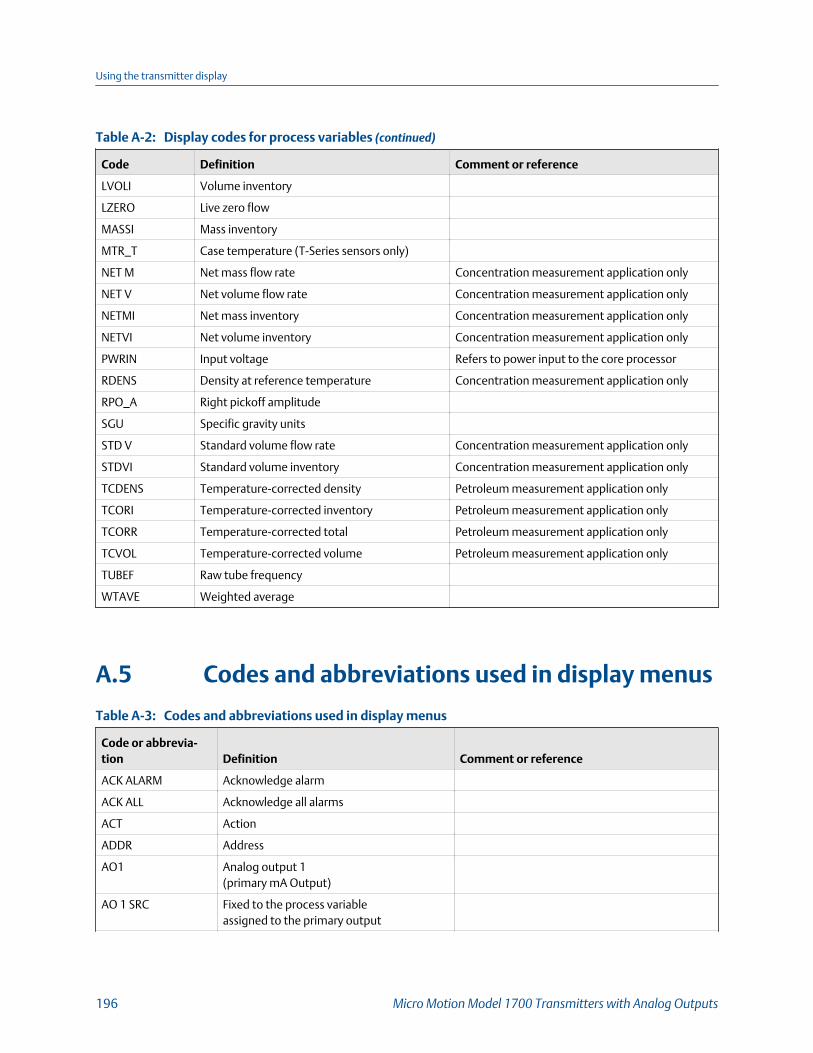
Display codes for process variables (continued)Table A-2:
Code Definition Comment or reference
LVOLI Volume inventory
LZERO Live zero flow
MASSI Mass inventory
MTR_T Case temperature (T-Series sensors only)
NET M Net mass flow rate Concentration measurement application only
NET V Net volume flow rate Concentration measurement application only
NETMI Net mass inventory Concentration measurement application only
NETVI Net volume inventory Concentration measurement application only
PWRIN Input voltage Refers to power input to the core processor
RDENS Density at reference temperature Concentration measurement application only
RPO_A Right pickoff amplitude
SGU Specific gravity units
STD V Standard volume flow rate Concentration measurement application only
STDVI Standard volume inventory Concentration measurement application only
TCDENS Temperature-corrected density Petroleum measurement application only
TCORI Temperature-corrected inventory Petroleum measurement application only
TCORR Temperature-corrected total Petroleum measurement application only
TCVOL Temperature-corrected volume Petroleum measurement application only
TUBEF Raw tube frequency
WTAVE Weighted average
A.5 Codes and abbreviations used in display menus
Codes and abbreviations used in display menusTable A-3:
Code or abbrevia-tion Definition Comment or reference
ACK ALARM Acknowledge alarm
ACK ALL Acknowledge all alarms
ACT Action
ADDR Address
AO1 Analog output 1(primary mA Output)
AO 1 SRC Fixed to the process variableassigned to the primary output
Using the transmitter display
196 Micro Motion Model 1700 Transmitters with Analog Outputs
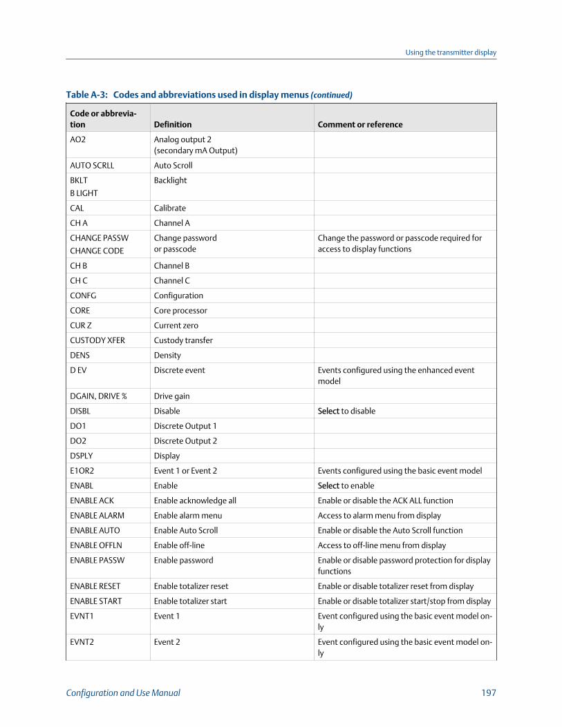
Codes and abbreviations used in display menus (continued)Table A-3:
Code or abbrevia-tion Definition Comment or reference
AO2 Analog output 2(secondary mA Output)
AUTO SCRLL Auto Scroll
BKLT
B LIGHT
Backlight
CAL Calibrate
CH A Channel A
CHANGE PASSW
CHANGE CODE
Change passwordor passcode
Change the password or passcode required foraccess to display functions
CH B Channel B
CH C Channel C
CONFG Configuration
CORE Core processor
CUR Z Current zero
CUSTODY XFER Custody transfer
DENS Density
D EV Discrete event Events configured using the enhanced eventmodel
DGAIN, DRIVE % Drive gain
DISBL Disable Select to disable
DO1 Discrete Output 1
DO2 Discrete Output 2
DSPLY Display
E1OR2 Event 1 or Event 2 Events configured using the basic event model
ENABL Enable Select to enable
ENABLE ACK Enable acknowledge all Enable or disable the ACK ALL function
ENABLE ALARM Enable alarm menu Access to alarm menu from display
ENABLE AUTO Enable Auto Scroll Enable or disable the Auto Scroll function
ENABLE OFFLN Enable off-line Access to off-line menu from display
ENABLE PASSW Enable password Enable or disable password protection for displayfunctions
ENABLE RESET Enable totalizer reset Enable or disable totalizer reset from display
ENABLE START Enable totalizer start Enable or disable totalizer start/stop from display
EVNT1 Event 1 Event configured using the basic event model on-ly
EVNT2 Event 2 Event configured using the basic event model on-ly
Using the transmitter display
Configuration and Use Manual 197

Codes and abbreviations used in display menus (continued)Table A-3:
Code or abbrevia-tion Definition Comment or reference
EXTRN External
FAC Z Factory zero
FCF Flow calibration factor
FLDIR Flow direction
FL SW
FLSWT
Flow switch
FO Frequency Output
FO FREQ Frequency factor
FO RATE Rate factor
FREQ Frequency
FR FL Frequency=Flow
GSV Gas standard volume
HYSTRSIS Hysteresis
INTERN Internal
IO Input/output
LANG Language
LOCK Write-protect
LOOP CUR Loop current
M_ASC Modbus ASCII
M_RTU Modbus RTU
MAO1 mA Output 1(primary mA Output)
MAO2 mA Output 2(secondary mA Output)
MASS Mass flow
MBUS Modbus
MFLOW Mass flow
MSMT Measurement
MTR F Meter factor
OFF-LINE MAINT Off-line maintenance
OFFLN Off-line
OIL Uncorrected oil flow PVR applications only
OIL60 Corrected Net Oil Flow PVR applications only
P/UNT Pulses/unit
POLAR Polarity
PRESS Pressure
Using the transmitter display
198 Micro Motion Model 1700 Transmitters with Analog Outputs

Codes and abbreviations used in display menus (continued)Table A-3:
Code or abbrevia-tion Definition Comment or reference
QUAD Quadrature
r. Revision
SCALE Scaling method
SFM60 Shrinkage factorcorrected volume of mix at 60F
PVR applications only
SFO60 Shrinkage Fac CorrNet Oil Total at Reference
PVR applications only
SIM Simulation Used for loop testing, not simulation mode. Sim-ulation mode is not accessible through the dis-play.
SPECL Special
SRC Source Variable assignment
TEMP, TEMPR Temperature
UNT/P Units/pulse
VAR 1 Display Variable 1
VER Version
VERFY Verify
VFLOW Volume flow
VOL Volume, volume flow
WATER Uncorrected NetWater Flow Rate
PVR applications only
WATER% Uncorrected Water Cut PVR applications only
WCT60% Water Cut 60F PVR applications only
WRPRO Write protect PVR applications only
WTR60 Corrected NetWater Flow
PVR applications only
XMTR Transmitter
Using the transmitter display
Configuration and Use Manual 199

Using the transmitter display
200 Micro Motion Model 1700 Transmitters with Analog Outputs

Appendix BUsing ProLink III with the transmitter
Topics covered in this appendix:
• Basic information about ProLink III
• Connect with ProLink III
B.1 Basic information about ProLink IIIProLink III is a configuration and service tool available from Micro Motion. ProLink III runson a Windows platform and provides complete access to transmitter functions and data.
Version requirements
To support all the latest firmware features, device firmware v8.0, ProLink III v4.0 or later isrequired. For details about ProLink III device support, refer to the ProLink III ChangeLog.txt file.
ProLink III requirements
To install ProLink III, you must have:
• The ProLink III installation media
• The ProLink III installation kit for your connection type:
To obtain ProLink III and the appropriate installation kit, contact customer support.
ProLink III documentation
Most of the instructions in this manual assume that you are already familiar with ProLink IIIor that you have a general familiarity with Windows programs. If you need moreinformation than this manual provides, see the ProLink® III Configuration and Service Tool forMicro Motion® Transmitters: User Manual.
In most ProLink III installations, the manual is installed with the ProLink III program.Additionally, the ProLink III manual is available on the documentation CD or at www.emerson.com.
ProLink III features and functions
ProLink III offers complete transmitter configuration and operation functions. ProLink IIIalso offers a number of additional features and functions, including:
• A Professional version with expanded features not available on the Basic version.
• The ability to save the transmitter configuration set to a file on the PC, and reload itor propagate it to other transmitters
• The ability to log specific types of data to a file on the PC
• The ability to view performance trends for various types of data on the PC
Using ProLink III with the transmitter
Configuration and Use Manual 201
• The ability to connect to and view information for more than one device
• A guided connection wizard
These features are documented in the ProLink III manual. They are not documented in thecurrent manual.
ProLink III messages
As you use ProLink III with a Micro Motion transmitter, you will see a number of messagesand notes. This manual does not document all of these messages and notes.
ImportantThe user is responsible for responding to messages and notes and complying with all safetymessages.
B.2 Connect with ProLink IIIA connection from ProLink III to your transmitter allows you to read process data,configure the transmitter, and perform maintenance and troubleshooting tasks.
B.2.1 Connection types supported by ProLink IIIDifferent connection types are available for connecting from ProLink III to the transmitter.Choose the connection type appropriate to your network and the tasks you intend toperform.
The transmitter supports the following ProLink III connection types:
• Service port connections
• HART/Bell 202 connections
• HART/RS-485 connections
• Modbus/RS-485 8-bit connections (Modbus RTU)
• Modbus/RS-485 7-bit connections (Modbus ASCII)
When selecting a connection type, consider the following:
• Service port connections are specialized Modbus/RS-485 connections that usestandard connection parameters and a standard address that are already defined inProLink III. A service port connection is the preferred connection.
• HART/Bell 202 connections use standard HART connection parameters that arealready defined in ProLink III. The only parameter you must configure is thetransmitter address.
• Some connection types require opening the wiring compartment or the powersupply compartment. These connection types should be used only for temporaryconnections, and may require extra safety precautions.
• When you are using a HART connection, ProLink III will not allow you to open morethan one window at a time. This is done to manage network traffic and optimizespeed.
Using ProLink III with the transmitter
202 Micro Motion Model 1700 Transmitters with Analog Outputs

• You cannot make concurrent Modbus connections if the connections use the sameterminals. You can make concurrent Modbus connections if the connections usedifferent terminals.
B.2.2 Connect with ProLink III to the service port
CAUTION!
If the transmitter is in a hazardous area, do not use a service port connection. Service portconnections require opening the wiring compartment, and opening the wiring compartmentwhile the transmitter is powered up could cause an explosion. To connect to the transmitter ina hazardous environment, use a connection method that does not require removing thetransmitter housing cover.
Prerequisites
• ProLink III is installed and licensed on your PC
• One of the following:
- RS-232 to RS-485 signal converter
- USB to RS-485 signal converter
• An available serial port or USB port
• Adapters as required (for example, 9-pin to 25-pin)
Procedure
1. Attach the signal converter to the serial port or USB port on your PC.
2. Access the service port terminals:
a. Remove the transmitter end-cap to access the wiring compartment.
b. Loosen the screw on the Warning flap and open the power supply compartment.
3. Connect the leads from the signal converter to the service port, terminals 7(RS-485/A) and 8 (RS-485/B).
TipUsually, but not always, the red lead is RS-485/A and the black lead is RS-485/B.
Using ProLink III with the transmitter
Configuration and Use Manual 203
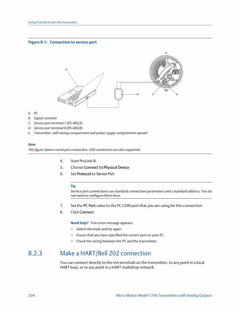
Connection to service portFigure B-1:
A
C D
E
B
A. PCB. Signal converterC. Service port terminal 7 (RS‐485/A)D. Service port terminal 8 (RS‐485/B)E. Transmitter, with wiring compartment and power supply compartment opened
NoteThis figure shows a serial port connection. USB connections are also supported.
4. Start ProLink III.
5. Choose Connect to Physical Device.
6. Set Protocol to Service Port.
TipService port connections use standard connection parameters and a standard address. You donot need to configure them here.
7. Set the PC Port value to the PC COM port that you are using for this connection.
8. Click Connect.
Need help? If an error message appears:
• Switch the leads and try again.
• Ensure that you have specified the correct port on your PC.
• Check the wiring between the PC and the transmitter.
B.2.3 Make a HART/Bell 202 connectionYou can connect directly to the mA terminals on the transmitter, to any point in a localHART loop, or to any point in a HART multidrop network.
Using ProLink III with the transmitter
204 Micro Motion Model 1700 Transmitters with Analog Outputs
CAUTION!
If the transmitter is in a hazardous area, do not connect directly to the transmitter terminals.Connecting directly to the transmitter terminals requires opening the wiring compartment,and opening the wiring compartment while the transmitter is powered up could cause anexplosion. To connect to the transmitter in a hazardous environment, use a connectionmethod that does not require opening the wiring compartment.
CAUTION!
If you connect directly to the mA terminals, the transmitter's mA Output may be affected. Ifyou are using the mA Output for process control, set devices for manual control beforeconnecting directly to the mA terminals.
Prerequisites
• ProLink III is installed and licensed on your PC
• One of the following:
- RS-232 to Bell 202 signal converter
- USB to Bell 202 signal converter
• An available serial port or USB port
• Adapters as required (for example, 9-pin to 25-pin)
Procedure
1. Attach the signal converter to the serial port or USB port on your PC.
2. To connect directly to the transmitter terminals:
a. Remove the transmitter end-cap to access the wiring compartment.
b. Connect the leads from the signal converter to terminals 1 and 2.
TipHART connections are not polarity-sensitive. It does not matter which lead you attach towhich terminal.
c. Add resistance as necessary to achieve at least one volt across the connectionpoints.
ImportantHART/Bell 202 connections require a voltage drop of 1 VDC. To achieve this, addresistance of 250–600 Ω to the connection.
Using ProLink III with the transmitter
Configuration and Use Manual 205
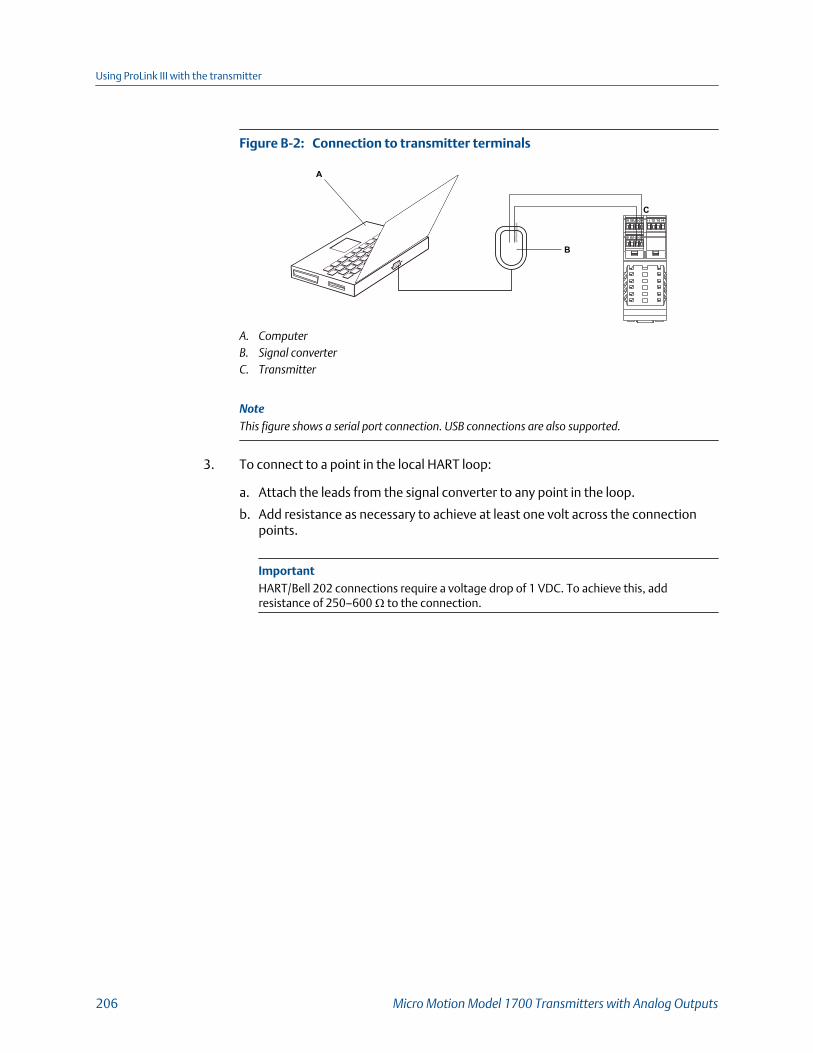
Connection to transmitter terminalsFigure B-2:
A
B
C
A. ComputerB. Signal converterC. Transmitter
NoteThis figure shows a serial port connection. USB connections are also supported.
3. To connect to a point in the local HART loop:
a. Attach the leads from the signal converter to any point in the loop.
b. Add resistance as necessary to achieve at least one volt across the connectionpoints.
ImportantHART/Bell 202 connections require a voltage drop of 1 VDC. To achieve this, addresistance of 250–600 Ω to the connection.
Using ProLink III with the transmitter
206 Micro Motion Model 1700 Transmitters with Analog Outputs

Connection over local loopFigure B-3:
A
C
D
E
R1
R3
R2
B
A. PCB. Signal converterC. Any combination of resistors R1, R2, and R3 as necessary to meet HART communication resistance requirementsD. DCS or PLCE. Transmitter, with wiring compartment and power supply compartment opened
NoteThis figure shows a serial port connection. USB connections are also supported.
4. To connect over a HART multidrop network:
a. Attach the leads from the signal converter to any point on the network.
b. Add resistance as necessary to achieve at least one volt across the connectionpoints.
ImportantHART/Bell 202 connections require a voltage drop of 1 VDC. To achieve this, addresistance of 250–600 Ω to the connection.
Using ProLink III with the transmitter
Configuration and Use Manual 207

Connection over multidrop networkFigure B-4:
B
AC
D
A. Signal converterB. 250–600 Ω resistanceC. Devices on the networkD. Master device
5. Start ProLink III.
6. Choose Connect to Physical Device.
7. Set Protocol to HART Bell 202.
TipHART/Bell 202 connections use standard connection parameters. You do not need toconfigure them here.
8. If you are using a USB signal converter, enable Toggle RTS.
9. Set Address/Tag to the HART polling address configured in the transmitter.
Tips
• If this is the first time you are connecting to the transmitter, use the default address: 0.
• If you are not in a HART multidrop environment, the HART polling address is typically leftat the default value.
• If you are unsure of the transmitter’s address, click Poll. The program will search thenetwork and return a list of the transmitters that it detects.
10. Set the PC Port value to the PC COM port that you are using for this connection.
11. Set Master as appropriate.
Option Description
Secondary Use this setting if a primary HART host such as a DCS is on the network.
Using ProLink III with the transmitter
208 Micro Motion Model 1700 Transmitters with Analog Outputs
Option Description
Primary Use this setting if no other primary host is on the network. TheField Communicator is a secondary host.
12. Click Connect.
Need help? If an error message appears:
• Verify the HART address of the transmitter, or poll HART addresses 1–15.
• Ensure that you have specified the correct port on your PC.
• Check the wiring between the PC and the transmitter.
• Increase or decrease resistance.
• Ensure that there is no conflict with another HART master. If any other host (DCS or PLC) isconnected to the mA Output, temporarily disconnect the DCS or PLC wiring.
B.2.4 Make a HART/RS-485 connectionUse a Modbus connection instead of a HART protocol whenever possible, as a Modbusconnection is faster.
You can connect directly to the RS-485 terminals on the transmitter or to any point on thenetwork.
CAUTION!
If the transmitter is in a hazardous area, do not connect directly to the transmitter terminals.Connecting directly to the transmitter terminals requires opening the wiring compartment,and opening the wiring compartment while the transmitter is powered up could cause anexplosion. To connect to the transmitter in a hazardous environment, use a connectionmethod that does not require opening the wiring compartment.
Prerequisites
• ProLink III installed and licensed on your PC
• One of the following:
- RS-232 to RS-485 signal converter
- USB to RS-485 signal converter
• An available serial port or USB port
• Adapters as required (for example, 9-pin to 25-pin)
Procedure
1. Attach the signal converter to the serial port or USB port on your PC.
2. To connect directly to the transmitter terminals:
a. Remove the transmitter end-cap to access the wiring compartment.
b. Connect the leads from the signal converter to terminals 5 (RS-485/A) and 6(RS-485/B).
Using ProLink III with the transmitter
Configuration and Use Manual 209
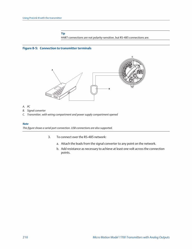
TipHART connections are not polarity-sensitive, but RS-485 connections are.
Connection to transmitter terminalsFigure B-5:
A
C
B
A. PCB. Signal converterC. Transmitter, with wiring compartment and power supply compartment opened
NoteThis figure shows a serial port connection. USB connections are also supported.
3. To connect over the RS-485 network:
a. Attach the leads from the signal converter to any point on the network.
b. Add resistance as necessary to achieve at least one volt across the connectionpoints.
Using ProLink III with the transmitter
210 Micro Motion Model 1700 Transmitters with Analog Outputs

Connection over networkFigure B-6:
A
C
E
D
B
A. PCB. Adapter, if necessaryC. Signal converterD. 120-Ω, 1/2‐watt resistors at both ends of the segment, if necessary for noise suppressionE. DCS or PLCF. Transmitter, with wiring compartment and power supply compartment opened
NoteThis figure shows a serial port connection. USB connections are also supported.
4. Start ProLink III.
5. Choose Connect to Physical Device.
6. Set the connection parameters to the values configured in the transmitter.
If your transmitter has not been configured, use the default values shown here.
Default HART/RS-485 connection parametersTable B-1:
Parameter Default values
Protocol HART (default factory setting on the RS-485 channel)
Baud 1200
Parity Odd
Stop Bits 1
Address 0
TipIf you do not know the transmitter’s RS-485 communication settings, you can connectthrough the service port, which always uses default settings, or use another communicationstool to view or change the settings.
7. Set the PC Port value to the PC COM port that you are using for this connection.
Using ProLink III with the transmitter
Configuration and Use Manual 211
8. Set Master as appropriate.
Option Description
Secondary Use this setting if a primary HART host such as a DCS is on the network.
Primary Use this setting if no other primary host is on the network. TheField Communicator is a secondary host.
9. Click Connect.
Need help? If an error message appears:
• Verify the HART address of the transmitter, or poll HART addresses 1–15.
• Ensure that you have specified the correct port on your PC.
• Check the wiring between the PC and the transmitter.
• Ensure that there is no conflict with another HART master. If any other host (DCS or PLC) isconnected to the mA output, temporarily disconnect the DCS or PLC wiring.
• For long-distance communication, or if noise from an external source interferes with thesignal, install 120-Ω ½-W terminating resistors in parallel with the output at both ends ofthe communication segment.
B.2.5 Connect with ProLink III to the RS-485 portYou can connect directly to the RS-485 terminals on the transmitter or to any point on thenetwork.
CAUTION!
If the transmitter is in a hazardous area, do not connect directly to the transmitter terminals.Connecting directly to the transmitter terminals requires opening the wiring compartment,and opening the wiring compartment while the transmitter is powered up could cause anexplosion. To connect to the transmitter in a hazardous environment, use a connectionmethod that does not require opening the wiring compartment.
Prerequisites
• ProLink III is installed and licensed on your PC.
• One of the following:
- RS-232 to RS-485 signal converter
- USB to RS-485 signal converter
• An available serial port or USB port
• Adapters as required (for example, 9-pin to 25-pin)
Procedure
1. Attach the signal converter to the serial port or USB port on your PC.
2. To connect directly to the transmitter terminals:
Using ProLink III with the transmitter
212 Micro Motion Model 1700 Transmitters with Analog Outputs
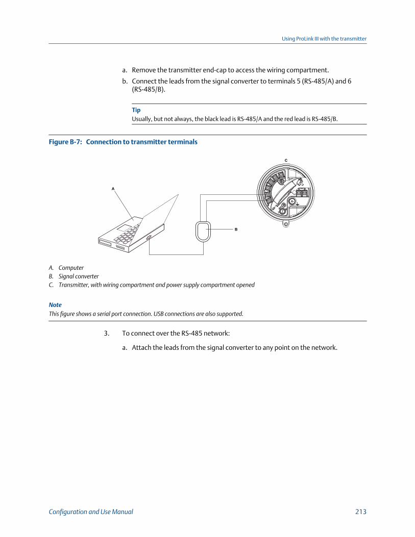
a. Remove the transmitter end-cap to access the wiring compartment.
b. Connect the leads from the signal converter to terminals 5 (RS-485/A) and 6(RS-485/B).
TipUsually, but not always, the black lead is RS-485/A and the red lead is RS-485/B.
Connection to transmitter terminalsFigure B-7:
A
C
B
A. ComputerB. Signal converterC. Transmitter, with wiring compartment and power supply compartment opened
NoteThis figure shows a serial port connection. USB connections are also supported.
3. To connect over the RS-485 network:
a. Attach the leads from the signal converter to any point on the network.
Using ProLink III with the transmitter
Configuration and Use Manual 213
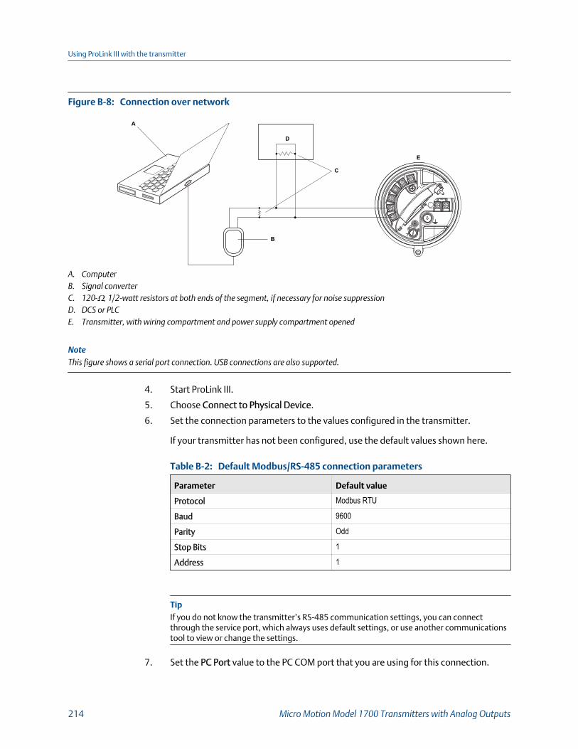
Connection over networkFigure B-8:
A
C
E
D
B
A. ComputerB. Signal converterC. 120-Ω, 1/2‐watt resistors at both ends of the segment, if necessary for noise suppressionD. DCS or PLCE. Transmitter, with wiring compartment and power supply compartment opened
NoteThis figure shows a serial port connection. USB connections are also supported.
4. Start ProLink III.
5. Choose Connect to Physical Device.
6. Set the connection parameters to the values configured in the transmitter.
If your transmitter has not been configured, use the default values shown here.
Default Modbus/RS-485 connection parametersTable B-2:
Parameter Default value
Protocol Modbus RTU
Baud 9600
Parity Odd
Stop Bits 1
Address 1
TipIf you do not know the transmitter’s RS-485 communication settings, you can connectthrough the service port, which always uses default settings, or use another communicationstool to view or change the settings.
7. Set the PC Port value to the PC COM port that you are using for this connection.
Using ProLink III with the transmitter
214 Micro Motion Model 1700 Transmitters with Analog Outputs

8. Select Connect.
Need help? If an error message appears:
• Verify the Modbus address of the transmitter.
• Ensure that you have specified the correct port on your PC.
• Check the wiring between the PC and the transmitter.
• Increase or decrease resistance.
• For long-distance communication, or if noise from an external source interferes with thesignal, install 120-Ω ½-W terminating resistors in parallel with the output at both ends ofthe communication segment.
• Ensure that there is no concurrent Modbus communication to the transmitter.
Using ProLink III with the transmitter
Configuration and Use Manual 215

Using ProLink III with the transmitter
216 Micro Motion Model 1700 Transmitters with Analog Outputs

Appendix CUsing a Field Communicator with thetransmitter
Topics covered in this appendix:
• Basic information about the Field Communicator
• Connect with the Field Communicator
C.1 Basic information about the FieldCommunicatorThe Field Communicator is a handheld configuration and management tool that can beused with a variety of devices, including Micro Motion transmitters. It provides completeaccess to transmitter functions and data.
Field Communicator documentation
Most of the instructions in this manual assume that you are already familiar with theField Communicator and can perform the following tasks:
• Turn on the Field Communicator
• Navigate the Field Communicator menus
• Send configuration data to the device
• Use the alpha keys to enter information
If you are unable to perform these tasks, consult the Field Communicator manual beforeattempting to use the Field Communicator. The Field Communicator manual is availableon the documentation CD or at www.emerson.com.
Device descriptions (DDs)
In order for the Field Communicator to work with your device, the appropriate devicedescription (DD) must be installed: 1000 Mass flo, Dev v8, DD v1
To view the device descriptions that are installed on your Field Communicator:
1. At the HART application menu, press Utility > Available Device Descriptions.
2. Scroll the list of manufacturers and select Micro Motion, then scroll the list ofinstalled device descriptions.
If Micro Motion is not listed, or you do not see the required device description, use theField Communicator Easy Upgrade Utility to install the device description, or contactcustomer support.
Using a Field Communicator with the transmitter
Configuration and Use Manual 217
Field Communicator menus and messages
Many of the menus in this manual start with the On-Line menu. Ensure that you are able tonavigate to the On-Line menu.
As you use the Field Communicator with a Micro Motion transmitter, you will see a numberof messages and notes. This manual does not document all of these messages and notes.
ImportantThe user is responsible for responding to messages and notes and complying with all safetymessages.
Field Communicator with PVR, TBR, and TMR applications
Production Volume Reconciliation (PVR), Transient Bubble Remediation (TBR), andTransient Mist Remediation (TMR) are available only over HART with HART 7 enabled(default).
C.2 Connect with the Field CommunicatorA connection from the Field Communicator to your transmitter allows you to read processdata, configure the transmitter, and perform maintenance and troubleshooting tasks.
You can connect the Field Communicator to the mA terminals on the transmitter, to anypoint in a local HART loop, or to any point in a HART multidrop network.
CAUTION!
If the transmitter is in a hazardous area, do not connect the Field Communicator to the mAterminals on the transmitter. This connection requires opening the wiring compartment, andopening the wiring compartment in a hazardous area can cause an explosion.
Prerequisites
The following HART device description (DD) must be installed on the Field Communicator :1000 Mass flo, Dev v8, DD v1.
Procedure
1. To connect to the transmitter terminals:
a. Remove the cover from the wiring compartment.
b. Attach the leads from the Field Communicator to terminals 1 and 2 on thetransmitter and add resistance as required.
The Field Communicator must be connected across a resistance of 250–600 Ω.
TipHART connections are not polarity-sensitive. It does not matter which lead you attach towhich terminal.
Using a Field Communicator with the transmitter
218 Micro Motion Model 1700 Transmitters with Analog Outputs
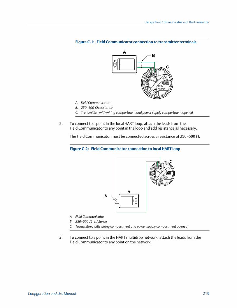
Field Communicator connection to transmitter terminalsFigure C-1:
A. Field CommunicatorB. 250–600 Ω resistanceC. Transmitter, with wiring compartment and power supply compartment opened
2. To connect to a point in the local HART loop, attach the leads from theField Communicator to any point in the loop and add resistance as necessary.
The Field Communicator must be connected across a resistance of 250–600 Ω.
Field Communicator connection to local HART loopFigure C-2:
A. Field CommunicatorB. 250–600 Ω resistanceC. Transmitter, with wiring compartment and power supply compartment opened
3. To connect to a point in the HART multidrop network, attach the leads from theField Communicator to any point on the network.
Using a Field Communicator with the transmitter
Configuration and Use Manual 219
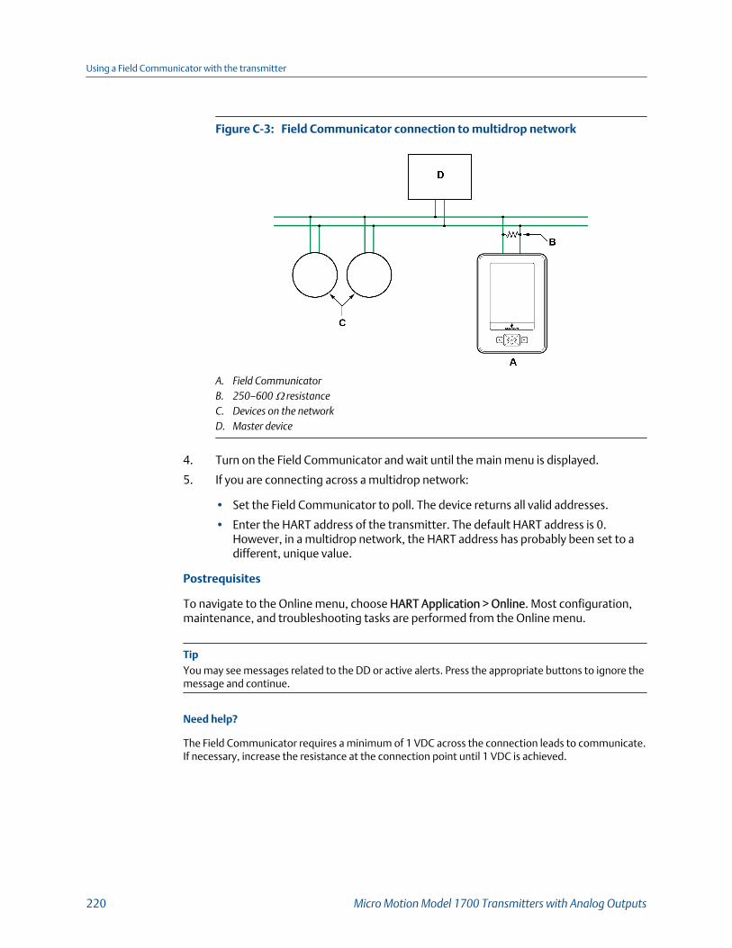
Field Communicator connection to multidrop networkFigure C-3:
A. Field CommunicatorB. 250–600 Ω resistanceC. Devices on the networkD. Master device
4. Turn on the Field Communicator and wait until the main menu is displayed.
5. If you are connecting across a multidrop network:
• Set the Field Communicator to poll. The device returns all valid addresses.
• Enter the HART address of the transmitter. The default HART address is 0.However, in a multidrop network, the HART address has probably been set to adifferent, unique value.
Postrequisites
To navigate to the Online menu, choose HART Application > Online. Most configuration,maintenance, and troubleshooting tasks are performed from the Online menu.
TipYou may see messages related to the DD or active alerts. Press the appropriate buttons to ignore themessage and continue.
Need help?
The Field Communicator requires a minimum of 1 VDC across the connection leads to communicate.If necessary, increase the resistance at the connection point until 1 VDC is achieved.
Using a Field Communicator with the transmitter
220 Micro Motion Model 1700 Transmitters with Analog Outputs

Appendix DDefault values and ranges
D.1 Default values and rangesThe default values and ranges represent the typical factory transmitter configuration.Depending on how the transmitter was ordered, certain values may have been configuredat the factory and are not represented in the default values and ranges.
Transmitter default values and rangesTable D-1:
Type Parameter Default Range Comments
Flow Flow direction Forward
Flow damping 0.8 sec(1) 0.0 – 51.2 sec User-entered value is correctedto the nearest valid value in listof preset values.In Special mode,the preset values are 1/5 nor-mal. For gas applications, a mini-mum value of 2.56 is recom-mended. The 2.56 value will beautomatically rounded up to 3.2seconds.
Flow calibration factor 1.00005.13 For sensors, this value repre-sents the FCF and FT factors con-catenated.
Mass flow units g/s
Mass flow cutoff Sensor-specificvalue set atfactory
For most sensors, the typical set-ting is 0.05% to 0.10% of the sen-sor's rated maximum flow rate.For some sensors, the settingmay be higher.
For some applications, such asempty-full-empty batching, ahigher value is recommended.Contact MMI customer servicefor assistance.
Volume flow type Liquid
Volume flow units L/s
Volume flow cutoff 0/0 L/s 0.0 – x L/s x is obtained by multiplying theflow calibration factor by 0.2, us-ing units of L/s.
Meter factors Mass factor 1
Density factor 1
Default values and ranges
Configuration and Use Manual 221
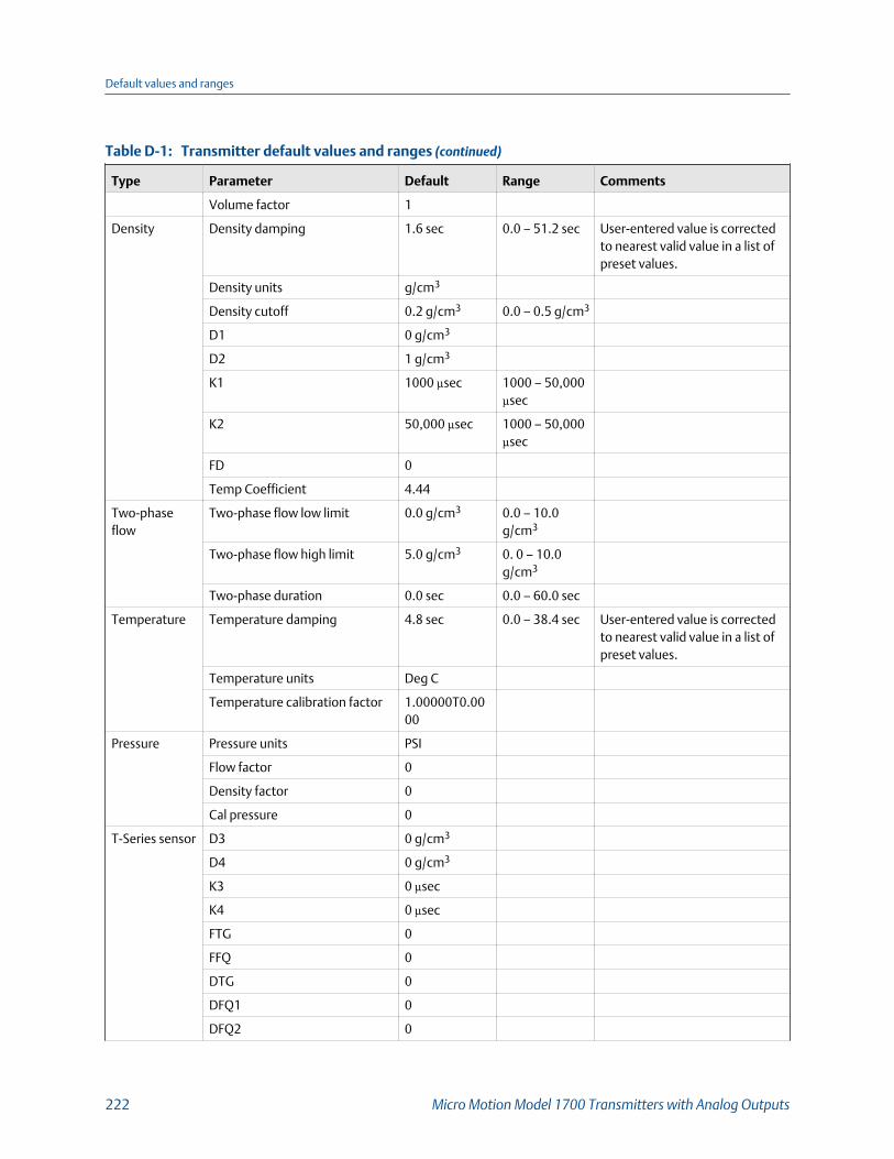
Transmitter default values and ranges (continued)Table D-1:
Type Parameter Default Range Comments
Volume factor 1
Density Density damping 1.6 sec 0.0 – 51.2 sec User-entered value is correctedto nearest valid value in a list ofpreset values.
Density units g/cm3
Density cutoff 0.2 g/cm3 0.0 – 0.5 g/cm3
D1 0 g/cm3
D2 1 g/cm3
K1 1000 µsec 1000 – 50,000µsec
K2 50,000 µsec 1000 – 50,000µsec
FD 0
Temp Coefficient 4.44
Two-phaseflow
Two-phase flow low limit 0.0 g/cm3 0.0 – 10.0g/cm3
Two-phase flow high limit 5.0 g/cm3 0. 0 – 10.0g/cm3
Two-phase duration 0.0 sec 0.0 – 60.0 sec
Temperature Temperature damping 4.8 sec 0.0 – 38.4 sec User-entered value is correctedto nearest valid value in a list ofpreset values.
Temperature units Deg C
Temperature calibration factor 1.00000T0.0000
Pressure Pressure units PSI
Flow factor 0
Density factor 0
Cal pressure 0
T-Series sensor D3 0 g/cm3
D4 0 g/cm3
K3 0 µsec
K4 0 µsec
FTG 0
FFQ 0
DTG 0
DFQ1 0
DFQ2 0
Default values and ranges
222 Micro Motion Model 1700 Transmitters with Analog Outputs
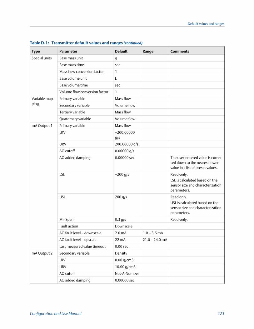
Transmitter default values and ranges (continued)Table D-1:
Type Parameter Default Range Comments
Special units Base mass unit g
Base mass time sec
Mass flow conversion factor 1
Base volume unit L
Base volume time sec
Volume flow conversion factor 1
Variable map-ping
Primary variable Mass flow
Secondary variable Volume flow
Tertiary variable Mass flow
Quaternary variable Volume flow
mA Output 1 Primary variable Mass flow
LRV –200.00000g/s
URV 200.00000 g/s
AO cutoff 0.00000 g/s
AO added damping 0.00000 sec The user-entered value is correc-ted down to the nearest lowervalue in a list of preset values.
LSL –200 g/s Read-only.
LSL is calculated based on thesensor size and characterizationparameters.
USL 200 g/s Read only.
USL is calculated based on thesensor size and characterizationparameters.
MinSpan 0.3 g/s Read-only.
Fault action Downscale
AO fault level – downscale 2.0 mA 1.0 – 3.6 mA
AO fault level – upscale 22 mA 21.0 – 24.0 mA
Last measured value timeout 0.00 sec
mA Output 2 Secondary variable Density
LRV 0.00 g/cm3
URV 10.00 g/cm3
AO cutoff Not-A-Number
AO added damping 0.00000 sec
Default values and ranges
Configuration and Use Manual 223
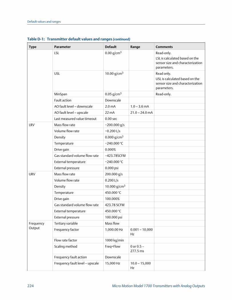
Transmitter default values and ranges (continued)Table D-1:
Type Parameter Default Range Comments
LSL 0.00 g/cm3 Read-only.
LSL is calculated based on thesensor size and characterizationparameters.
USL 10.00 g/cm3 Read only.
USL is calculated based on thesensor size and characterizationparameters.
MinSpan 0.05 g/cm3 Read-only.
Fault action Downscale
AO fault level – downscale 2.0 mA 1.0 – 3.6 mA
AO fault level – upscale 22 mA 21.0 – 24.0 mA
Last measured value timeout 0.00 sec
LRV Mass flow rate −200.000 g/s
Volume flow rate −0.200 L/s
Density 0.000 g/cm3
Temperature −240.000 °C
Drive gain 0.000%
Gas standard volume flow rate −423.78SCFM
External temperature −240.000 °C
External pressure 0.000 psi
URV Mass flow rate 200.000 g/s
Volume flow rate 0.200 L/s
Density 10.000 g/cm3
Temperature 450.000 °C
Drive gain 100.000%
Gas standard volume flow rate 423.78 SCFM
External temperature 450.000 °C
External pressure 100.000 psi
FrequencyOutput
Tertiary variable Mass flow
Frequency factor 1,000.00 Hz 0.001 – 10,000Hz
Flow rate factor 1000 kg/min
Scaling method Freq=Flow 0 or 0.5 –277.5 ms
Frequency fault action Downscale
Frequency fault level – upscale 15,000 Hz 10.0 – 15,000Hz
Default values and ranges
224 Micro Motion Model 1700 Transmitters with Analog Outputs
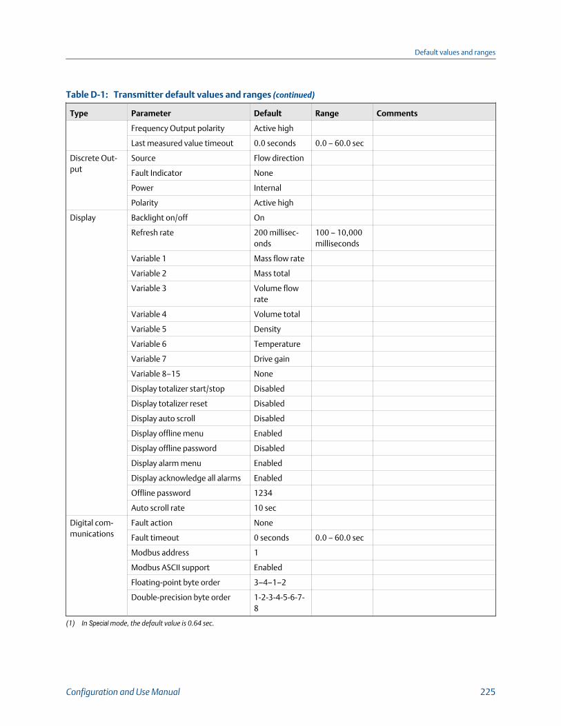
Transmitter default values and ranges (continued)Table D-1:
Type Parameter Default Range Comments
Frequency Output polarity Active high
Last measured value timeout 0.0 seconds 0.0 – 60.0 sec
Discrete Out-put
Source Flow direction
Fault Indicator None
Power Internal
Polarity Active high
Display Backlight on/off On
Refresh rate 200 millisec-onds
100 – 10,000milliseconds
Variable 1 Mass flow rate
Variable 2 Mass total
Variable 3 Volume flowrate
Variable 4 Volume total
Variable 5 Density
Variable 6 Temperature
Variable 7 Drive gain
Variable 8–15 None
Display totalizer start/stop Disabled
Display totalizer reset Disabled
Display auto scroll Disabled
Display offline menu Enabled
Display offline password Disabled
Display alarm menu Enabled
Display acknowledge all alarms Enabled
Offline password 1234
Auto scroll rate 10 sec
Digital com-munications
Fault action None
Fault timeout 0 seconds 0.0 – 60.0 sec
Modbus address 1
Modbus ASCII support Enabled
Floating-point byte order 3–4–1–2
Double-precision byte order 1-2-3-4-5-6-7-8
(1) In Special mode, the default value is 0.64 sec.
Default values and ranges
Configuration and Use Manual 225

Default values and ranges
226 Micro Motion Model 1700 Transmitters with Analog Outputs

Appendix ETransmitter components and installationwiring
Topics covered in this appendix:
• Installation types
• Power supply terminals and ground
• Input/output (I/O) wiring terminals
E.1 Installation typesThe transmitter was ordered and shipped to be installed in one of several possibleconfigurations.
Integral installationFigure E-1:
The transmitter is mounted directly to the sensor. Integral installations do not require separate transmitterinstallation. Power supply and I/O must be field wired to the transmitter.
A
B
A. TransmitterB. Sensor
Transmitter components and installation wiring
Configuration and Use Manual 227
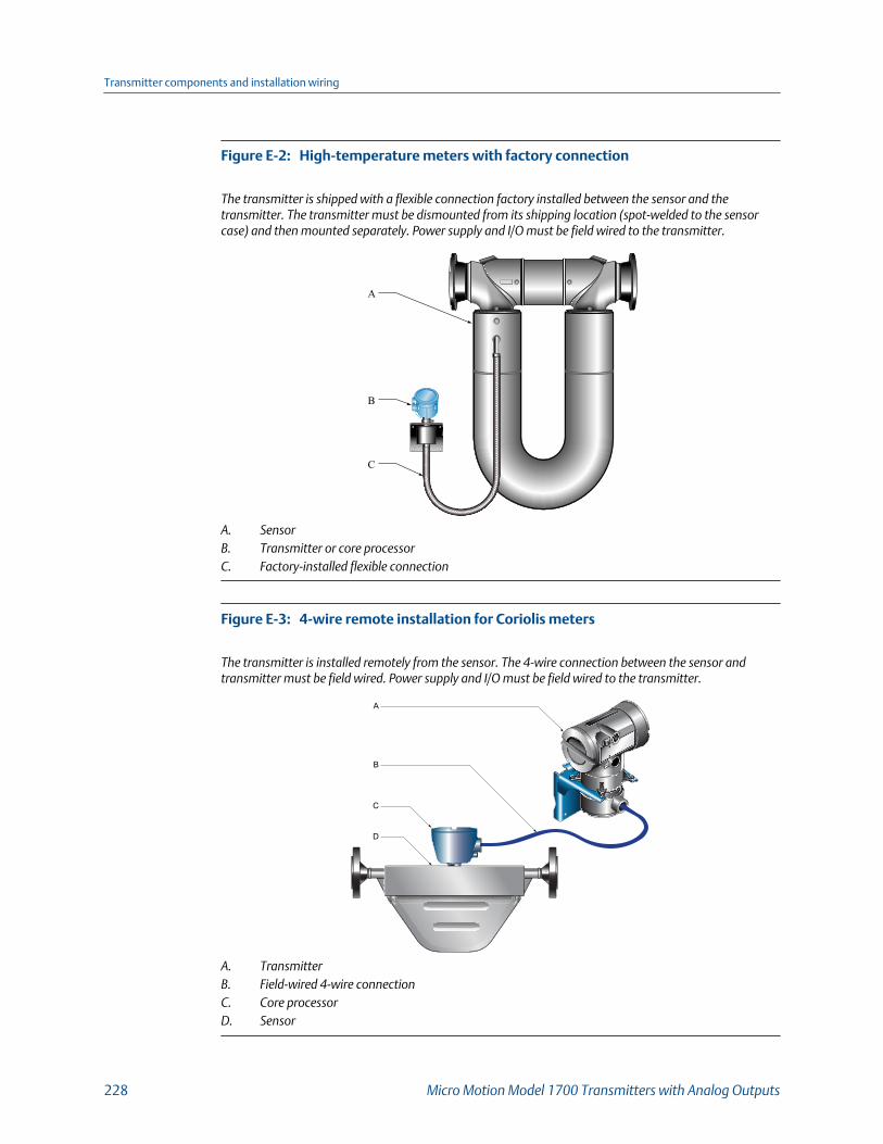
High-temperature meters with factory connectionFigure E-2:
The transmitter is shipped with a flexible connection factory installed between the sensor and thetransmitter. The transmitter must be dismounted from its shipping location (spot‐welded to the sensorcase) and then mounted separately. Power supply and I/O must be field wired to the transmitter.
A
B
C
A. SensorB. Transmitter or core processorC. Factory‐installed flexible connection
4-wire remote installation for Coriolis metersFigure E-3:
The transmitter is installed remotely from the sensor. The 4‐wire connection between the sensor andtransmitter must be field wired. Power supply and I/O must be field wired to the transmitter.
A
A
B
C
D
A. TransmitterB. Field‐wired 4‐wire connectionC. Core processorD. Sensor
Transmitter components and installation wiring
228 Micro Motion Model 1700 Transmitters with Analog Outputs
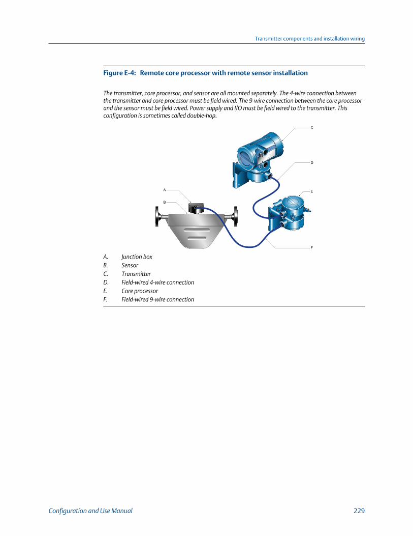
Remote core processor with remote sensor installationFigure E-4:
The transmitter, core processor, and sensor are all mounted separately. The 4‐wire connection betweenthe transmitter and core processor must be field wired. The 9‐wire connection between the core processorand the sensor must be field wired. Power supply and I/O must be field wired to the transmitter. Thisconfiguration is sometimes called double‐hop.
A E
D
C
F
B
A. Junction boxB. SensorC. TransmitterD. Field‐wired 4‐wire connectionE. Core processorF. Field‐wired 9‐wire connection
Transmitter components and installation wiring
Configuration and Use Manual 229
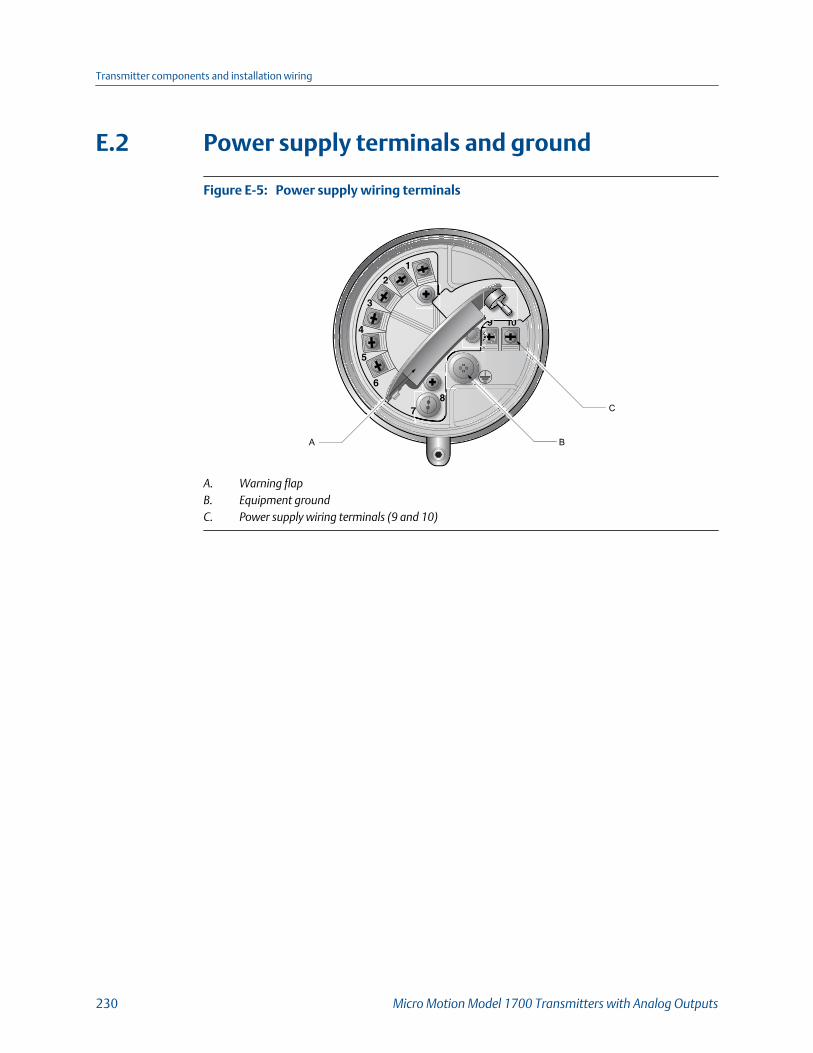
E.2 Power supply terminals and ground
Power supply wiring terminalsFigure E-5:
A B
C
A. Warning flapB. Equipment groundC. Power supply wiring terminals (9 and 10)
Transmitter components and installation wiring
230 Micro Motion Model 1700 Transmitters with Analog Outputs
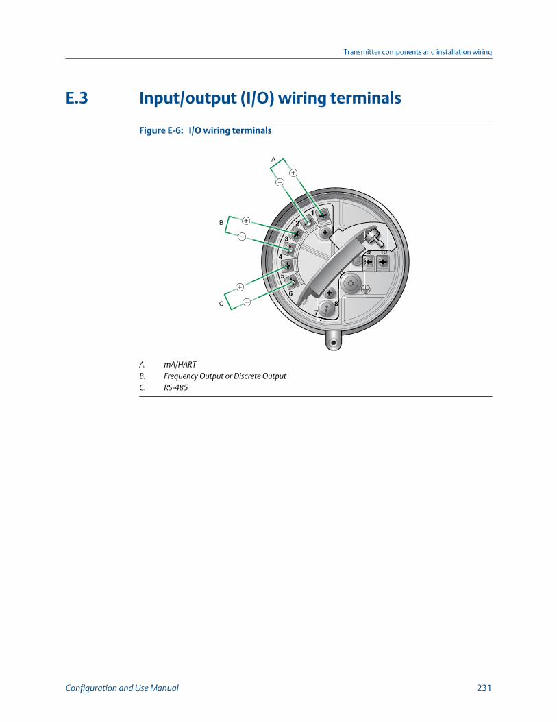
E.3 Input/output (I/O) wiring terminals
I/O wiring terminalsFigure E-6:
C
B
A
A. mA/HARTB. Frequency Output or Discrete OutputC. RS‐485
Transmitter components and installation wiring
Configuration and Use Manual 231

Transmitter components and installation wiring
232 Micro Motion Model 1700 Transmitters with Analog Outputs

Appendix FNE 53 history
F.1 NE 53 history
ImportantNot all features and capabilities described in this section may apply to your transmitter orconfiguration.
August 2000, Version 1.x
Modification type Change
Expansion Added writing of the device tag using Modbus
Adjustment Improved communication handling with the HART Tri-Loop prod-uct
Feature Indication of outputs option board type appears on display atpower-up
May 2001, version 2.x
Modification type Change
Expansion • Added alarm A106 to indicate that HART burst mode is ena-bled
• Indication of outputs option board type appears on display atpower-up
• Added alarm A106 to indicate that HART burst mode is ena-bled
• Control of HART burst mode now available via Modbus• Added support for the Model 1700 transmitter• Added support for the intrinsically safe transmitter option• Added support to configure the process variable units for
mass flow, volume flow, density and temperature from thedisplay
• Added support for assigning process variables to the mA andFrequency Output from the display
Adjustment Clarified the interaction of the digital fault setting and the faulttimeout (last measured value timeout)
Feature • Drive gain can be assigned to mA Output• Pressure compensation added via HART• Channel B can be configured as a Discrete Output
NE 53 history
Configuration and Use Manual 233

December 2001, version 3.x
Modification type Change
Expansion • Added support for the configurable I/O option board• Software version information available via the display or
Modbus• Configurable density cutoff• Additional HART variables can be assigned to QV• The display start/stop totalizers function can be enabled or
disabled• Petroleum measurement application improvements• Live zero available as display variable• Increased options for fault output settings• New cryogenic application temperature algorithms
Adjustment • Improved Frequency Output stability and unit conversions• Improved the handling of volume flow rate when two-phase
flow is detected• Improved handling of density values and calibrations during
fault conditions• Display configuration, screen flow and optical switch changes• HART communication and burst mode improvements
Feature • Petroleum measurement application added• Custody transfer option added to the configurable I/O option
board• HART polling for external pressure/temperature added
June 2003, version 4.x
Modification type Change
Expansion • Added support for the Model 1500 transmitter• Additional variables displayed by the Model 1700 transmitter
Adjustment • Improved the handling of certain alarm conditions• Clarified the behavior of certain Modbus calibration coils• Clarified the interaction between certain density measure-
ment units and density cutoff values• Improved the handling of the mA source setting via the dis-
play• Improvements to pressure and temperature polling• HART Tri-Loop and other communication improvements• Clarified the value returned by Modbus scaled integer regis-
ters during a fault condition
Feature Discrete values now available through Modbus
NE 53 history
234 Micro Motion Model 1700 Transmitters with Analog Outputs
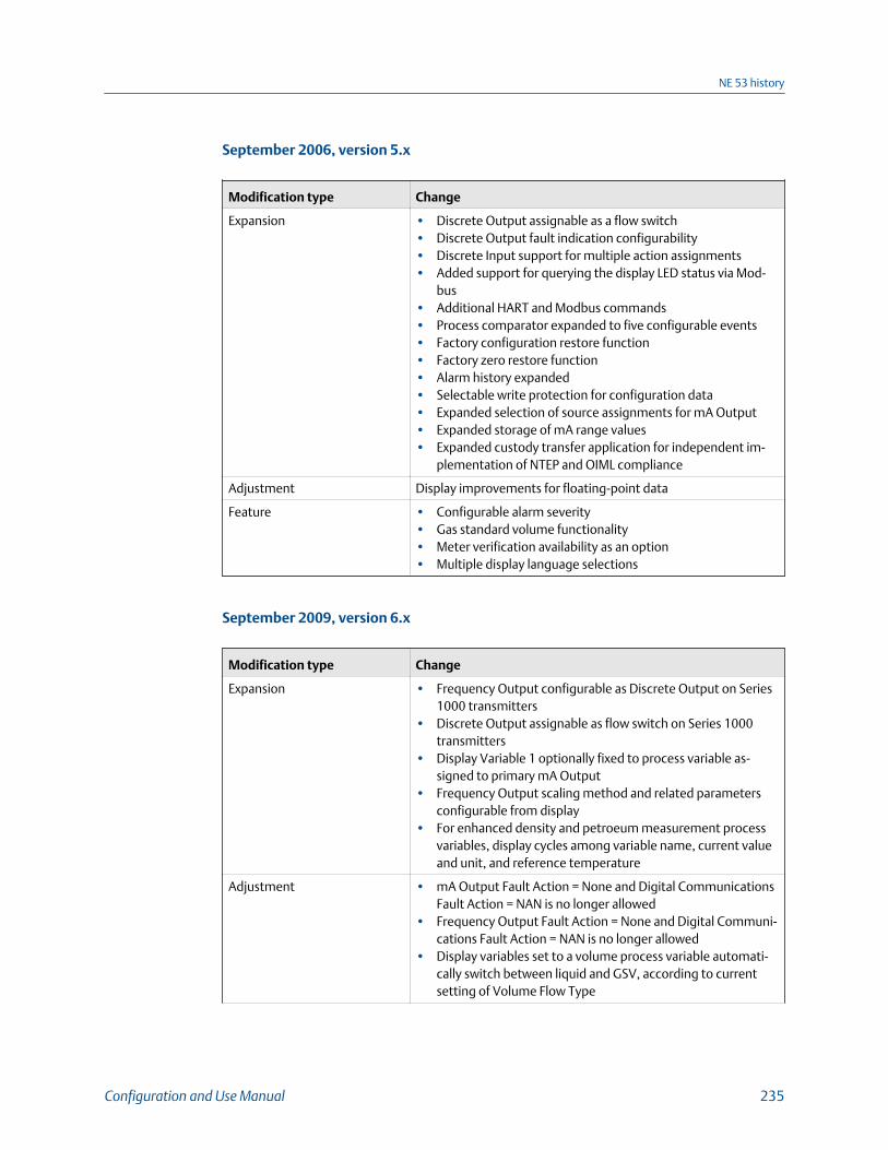
September 2006, version 5.x
Modification type Change
Expansion • Discrete Output assignable as a flow switch• Discrete Output fault indication configurability• Discrete Input support for multiple action assignments• Added support for querying the display LED status via Mod-
bus• Additional HART and Modbus commands• Process comparator expanded to five configurable events• Factory configuration restore function• Factory zero restore function• Alarm history expanded• Selectable write protection for configuration data• Expanded selection of source assignments for mA Output• Expanded storage of mA range values• Expanded custody transfer application for independent im-
plementation of NTEP and OIML compliance
Adjustment Display improvements for floating-point data
Feature • Configurable alarm severity• Gas standard volume functionality• Meter verification availability as an option• Multiple display language selections
September 2009, version 6.x
Modification type Change
Expansion • Frequency Output configurable as Discrete Output on Series1000 transmitters
• Discrete Output assignable as flow switch on Series 1000transmitters
• Display Variable 1 optionally fixed to process variable as-signed to primary mA Output
• Frequency Output scaling method and related parametersconfigurable from display
• For enhanced density and petroeum measurement processvariables, display cycles among variable name, current valueand unit, and reference temperature
Adjustment • mA Output Fault Action = None and Digital CommunicationsFault Action = NAN is no longer allowed
• Frequency Output Fault Action = None and Digital Communi-cations Fault Action = NAN is no longer allowed
• Display variables set to a volume process variable automati-cally switch between liquid and GSV, according to currentsetting of Volume Flow Type
NE 53 history
Configuration and Use Manual 235
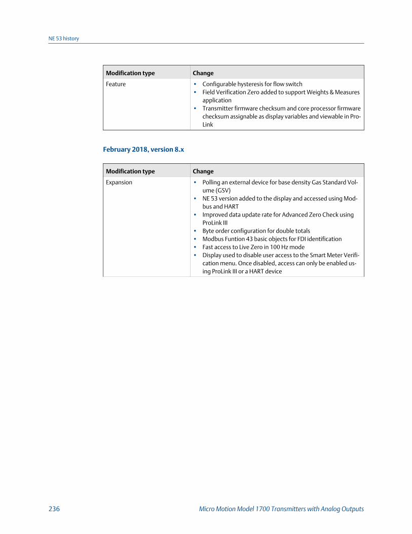
Modification type Change
Feature • Configurable hysteresis for flow switch• Field Verification Zero added to support Weights & Measures
application• Transmitter firmware checksum and core processor firmware
checksum assignable as display variables and viewable in Pro-Link
February 2018, version 8.x
Modification type Change
Expansion • Polling an external device for base density Gas Standard Vol-ume (GSV)
• NE 53 version added to the display and accessed using Mod-bus and HART
• Improved data update rate for Advanced Zero Check usingProLink III
• Byte order configuration for double totals• Modbus Funtion 43 basic objects for FDI identification• Fast access to Live Zero in 100 Hz mode• Display used to disable user access to the Smart Meter Verifi-
cation menu. Once disabled, access can only be enabled us-ing ProLink III or a HART device
NE 53 history
236 Micro Motion Model 1700 Transmitters with Analog Outputs

Modification type Change
Adjustment • Sensors that are not straight tube sensors are now correctlyidentified
• The mA Output fixed alert is now set• The Factory Configuration Invalid status bit is now set cor-
rectly when connected to a 700 core processor — as the 700core processor does not support saving and restoring the fac-tory configuration
• Enabling a new feature on a flow-only device does not resetthe output configuration to factory defaults
• Polled variables are now converted to the transmitter unitsbefore being used
• HART Primary, Secondary, and Tertiary Variables can bechanged using HART when the transmitter is configured forgas standard volume
• Petroleum measurement variables are removed from the dis-play when petroleum measurement is disabled
• The mA Output can be fixed when assigned to a concentra-tion measurement, petroleum measurement, or GSV variablewhen the transmitter is not connected to a core processor
• The units for concentration curve data are correctly conver-ted when the data is entered using HART
• Meter verification failed and aborted alerts are now reflectedin the HART More Status flag
• The HART Squawk command is functional when the HARTwrite protect is enabled
• Locking the transmitter, unlocking the transmitter, or chang-ing write protection does not set the HART ConfigurationChanged flag
• If connected to a 700 core processor with software version3.1 or earlier, there is no longer a core processor write failedalert when setting volume flow units to beer barrels per timeunit
• The factory zero value is immediately updated from the coreprocessor after running a zero calibration and saving the fac-tory configuration
• A firmware upgrade done without clearing non-volatile mem-ory no longer causes an EEPROM Failure alert
• The status bit for the undefined A141 alert (Device Data Cap-ture Triggered) no longer appears in the Modbus status regis-ter
• When using AMS to configure the transmitter:- Changing the output configuration for mA 1, mA 2, or the
Frequency Output, does not change the configuration ofall three outputs
- mA configuration methods can be cancelled- Density and temperature units display on the concentra-
tion measurement configuration page
NE 53 history
Configuration and Use Manual 237

Modification type Change
- An AMS Field Device did not respond message
no longer displays when the concentration offset is con-figured even though the value was changed
- When the volume flow type is changed, the new setting isupdated from the transmitter without having to rescanthe device
Feature • Basic meter verification• Production Volume Reconciliation (PVR)• Transient Mist Remediation (TMR)• Transient Bubble Remediation (TBR)• Piecewise Linearization for Gas• Fuel consumption• Support for Micro Load
NE 53 history
238 Micro Motion Model 1700 Transmitters with Analog Outputs

NE 53 history
Configuration and Use Manual 239

*MMI-20019028*MMI-20019028
Rev AB
2018
Micro Motion Inc. USAWorldwide Headquarters7070 Winchester CircleBoulder, Colorado USA 80301T +1 303-527-5200T +1 800-522-6277F +1 303-530-8459www.emerson.com
Micro Motion EuropeEmerson Automation SolutionsNeonstraat 16718 WX EdeThe NetherlandsT +31 (0) 70 413 6666F +31 (0) 318 495 556www.micromotion.nl
Micro Motion AsiaEmerson Automation Solutions1 Pandan CrescentSingapore 128461Republic of SingaporeT +65 6777-8211F +65 6770-8003
Micro Motion United KingdomEmerson Automation SolutionsEmerson Process Management LimitedHorsfield WayBredbury Industrial EstateStockport SK6 2SU U.K.T +44 0870 240 1978F +44 0800 966 181
Micro Motion JapanEmerson Automation Solutions1-2-5, Higashi ShinagawaShinagawa-kuTokyo 140-0002 JapanT +81 3 5769-6803F +81 3 5769-6844
©2018 Micro Motion, Inc. All rights reserved.
The Emerson logo is a trademark and service mark of Emerson Electric Co. Micro Motion, ELITE,ProLink, MVD and MVD Direct Connect marks are marks of one of the Emerson AutomationSolutions family of companies. All other marks are property of their respective owners.