user manual installation checklist - solar power & panels | water … dealer/technical... ·...
TRANSCRIPT

Ver 12/2012
INSTALLATION CHECKLIST
� Air b
led fro
m taps
� System checked for glycol pressu
re drop or le
aks
� Cold and hot w
ater piping checked for w
ater le
aks
� Roof tile
s put back into positio
n
� Drain pipes fre
e of any obstru
ction
� All pipe work clip
ped where necessa
ry
� All hot pipes are lagged
� Operation of element ch
ecked
� Solar co
ntroller co
nnected
� Operation of so
lar pump checked
� Thermal paste is u
sed with sensor probes
� Solar circu
lation pump and flo
w meter sp
eed set
� Solar circu
it runs sm
oothly and air p
ocket is le
ft in expansion chamber
� Owner in
structed on use and controller and service stick
er m
ounted
USER MANUAL
Solar Group Accre
dited Installer
Ver 12/2012
INSTALLATION IN
STRUCTION
OPERATION & REGULAR CARE
SOLAR W
ATER HEATERS MODEL:
Solarhart G
reenGlo and GreenGlo Max
180S 180D 300S 300D 300DS
400D 500D 800D 1000D
Customer / U
ser
Congratulations fo
r choosing a Solahart G
reenGlo water heater
We recommend you read page 1 to 7 of th
is manual.
It may save you tim
e and tro
uble later.
The other pages of th
e manual are intended for th
e installer.
For fu
rther assista
nce or in
formation contact o
ur se
rvice desk
� 0800 769 377 �

Ver 12/2012
IMPORTANT IN
FORMATION
This m
anual re
fers to
the Solahart G
reenGlo and GreenGlo Max System with
Glycol in the panels.
If panels a
re to be fille
d with water, so
me of th
ese instru
ctions do not apply.
The Solahart G
reenGlo hot w
ater sy
stems are to be installed in acco
rdance with
the cylinders m
anufactu
rer’s in
stallation instru
ctions, lo
cal and NZ.3500.4
national plumbing regulations, m
unicip
al building codes, N
ZBC G12 and any
other re
levant sta
tutory regulations.
Observation of th
ese instru
ctions and the asso
ciated component in
structio
ns is
most im
portant and failure to do so could void the benefits o
f warranty.
All w
ork is to
be carrie
d out by appropriately qualifie
d tra
des people or to
be
suitably supervised for tra
de assista
nt duties, a
nd to be carrie
d out in
acco
rdance with Local and National Occu
pational Safety Guidelines.
The information contained in this m
anual, a
nd all other in
formation or advice
provided by Solar Group Limited in connectio
n with the purch
ase, in
stallation
use and service of w
ater heaters, is g
iven in good faith. Solar Group Limited will
not be liable for any perso
n for any inaccu
racy or omissio
n in the information
arisin
g through the fault o
f Solar Group Limited directly
or in
directly
.
A pressu
re-lim
iting valve of 500kPa max rating must b
e fitte
d. Failure to install
a pressu
re lim
iting valve where required will v
oid the warranty.
SAFETY
Ensure compliance with safety regulations of w
orking at heights o
n roofs.
Scalding occu
rs at 500C. This a
ppliance is ca
pable of providing hot w
ater above
this te
mperature. All in
stallers m
ust a
dvise cu
stomers o
f the potential hazard of
scalding in acco
rdance with the relevant National sta
ndards in
cluding NZ3500.4.
A solar-ra
ted tempering valve must b
e fitte
d on the hot outlet of th
e tank
Young children should not play with the appliance.
Care must b
e taken when fix
ing or re
placing broken glass. C
ollectors h
ave
toug
hen
ed g
lass c
om
plie
s w
ith N
ZS
4223
.1 a
nd N
ZS
4223.4
. No
oth
er g
lass
shall be used.
Please refer to
page 1 of th
e GreenGlo manual fo
r further sa
fety issu
es w
ith the
mains pressu
re water sto
rage cylinder.
1
Ver 12/2012
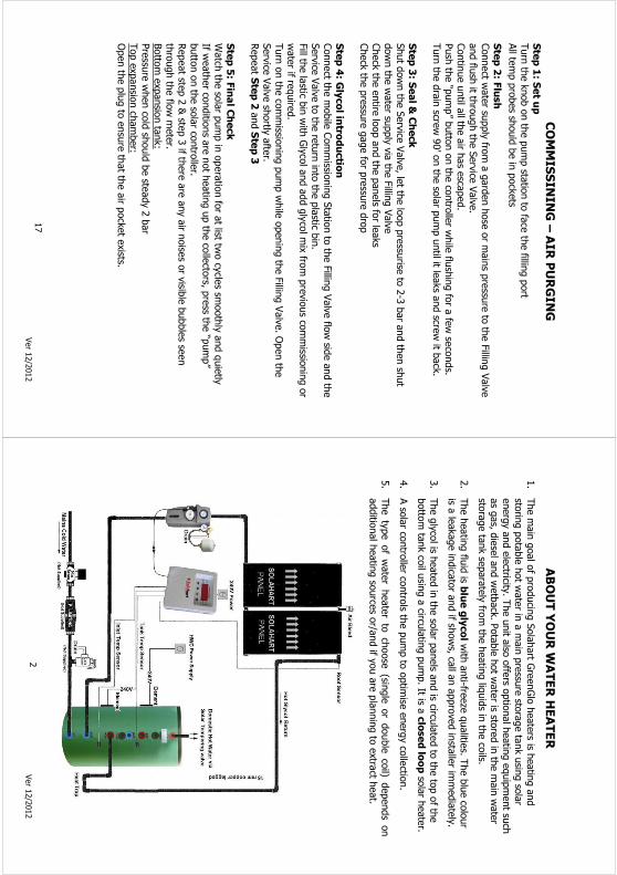
COMMISSINING – AIR PURGING SCHEMATIC
18
Ver 12/2012
COMMISSINING – AIR PURGING
Step 1: S
et u
p
Turn the knob on the pump sta
tion to face the fillin
g port
All te
mp probes sh
ould be in pockets
Step 2: Flush
Connect w
ater su
pply fro
m a garden hose or m
ains pressu
re to the Fillin
g Valve
and flu
sh it th
rough the Service Valve.
Continue until a
ll the air h
as esca
ped.
Push the “pump” button on the controller w
hile flu
shing for a few seconds.
Turn the drain scre
w 90’ on the solar pump until it le
aks and scre
w it b
ack.
Step 3: S
eal &
Check
Shut down the Service Valve, le
t the loop pressu
rise to 2-3 bar and then shut
down the water su
pply via the Fillin
g Valve
Check the entire
loop and the panels fo
r leaks
Check the pressu
re gage for pressu
re drop
Step 4: G
lycol in
troductio
n
Connect th
e mobile Commissio
ning Station to the Fillin
g Valve flo
w sid
e and the
Service Valve to the return into the plastic b
in.
Fill th
e lastic b
in with Glycol and add glycol m
ix fro
m previous co
mmissio
ning or
water if re
quired.
Turn on the commissio
ning pump while opening the Fillin
g Valve. Open the
Service Valve shortly
after.
Repeat S
tep 2 and Step 3
Step 5: Final Check
Watch the solar pump in operation for at list tw
o cycles sm
oothly and quietly
If weather co
nditions are not heating up the collectors, p
ress th
e “pump”
button on the solar co
ntroller.
Repeat ste
p 2 & ste
p 3 if th
ere are any air n
oises or visib
le bubbles se
en
through the flo
w meter.
Bottom expansion tank:
Pressu
re when cold should be ste
ady 2 bar
Top expansion chamber:
Open the plug to ensure that th
e air p
ocket exists.
17
Ver 12/2012
ABOUT YOUR W
ATER HEATER
1. The main goal of producing Solahart G
reenGlo heaters is h
eating and
storing potable hot w
ater in
a main pressu
re sto
rage tank using solar
energy and electricity
. The unit a
lso offers o
ptional heating equipment su
ch
as gas, d
iesel and wetback. Potable hot w
ater is sto
red in the main water
storage tank separately fro
m the heating liquids in
the coils.
2. The heating flu
id is b
lue glycol w
ith anti-fre
eze qualitie
s. The blue colour
is a leakage indicator and if sh
ows, ca
ll an approved installer im
mediately.
3. The glycol is h
eated in the solar panels a
nd is circu
lated to the top of th
e
bottom tank coil using a circu
lating pump. It is a
closed loop solar heater.
4. A solar co
ntroller co
ntrols th
e pump to optim
ise energy collectio
n.
5. The type of water heater to choose (sin
gle or double coil)
depends on
additional heating source
s or/and if y
ou are planning to extract h
eat.
2

Ver 12/2012
PRODUCT IN
FORMATION
GreenGlo Mild Steel D
ouble Enamelled Cylinder:
180S 300S 180D 300D 300DS400D 500D 800D
1000D
Single Coil
S Serie
s
Double Coil &
Element
D Serie
s
Volume (litre
s) 180
300
180
300
300
400
500
800
1,000
Height (m
m)
1650 1780 1650
1780
1240
1580
1860
1900
2090
Diameter (m
m)
520
615
520
615
755
755
755
1060
1060
No. of panels
1-2
2-3
1-2
2-3
2-3
3-4
3-5
5-8
6-10
Glycol (ltr)
2-3
3-4
2-3
3-4
3-4
4-5
4-6
6-9
7-11
Expansion (ltr)
0.5
0.5
0.5
0.5/7.5 0.5/7.5
7.5
7.5
7.5
7.5
Please refer to
page 3 & 4 of th
e GreenGlo manual fo
r more technical information
GreenGlo Max Duplex Stainless Steel Cylinder:
Volume (litre
s) 180
180T
300
400
Height (m
m)
1100 1200
1800
1850
Diameter (m
m)
575
535
575
630
No. of panels
1-2
1-2
2
3
Glycol (ltr)
2-3
2-3
3-4
4-5
Panel (c
ollectors):
Dimensions (e
ach): 1
.94m x 1.03m x 0.083m
Weight (fu
ll): 37.6Kg
Insulatio
n:
38mm Glass W
ool
Weight (d
ry): 3
5Kg
Max Pressure:
1400kPa
Ports
:
20mm
Surfa
ce Types:
Black Carbon / B
T Selectiv
e Coating Titanium Blue
Circulatio
n Pump / Flow Meter:
Standard: Three speed max power of 90w
Flow meter: 2
-8 l/m
in
For m
ore technical information, re
fer to
the specific p
ump manual
Solar C
ontro
ller:
Smart co
ntroller: P
ower Pump Plus: 1
0m 3 temp probes; b
ooster co
ntroller and
digital display
A relay for rip
ple power or lo
ad of 3kW or m
ore is e
ssential
For m
ore te
chnical in
form
atio
n, please re
fer to
the contro
ller m
anual
3
Ver 12/2012
START-UP AND COMMISSIONING
Fillin
g th
e ta
nk with
water
Follow the instru
ctions of th
e GreenGlo Manual
WARNING:
Ensure that th
e tank is fu
ll before turning on the electric p
ower,
solar pump or any other heat so
urce
Fillin
g th
e solar circuit w
ith glycol m
ixture
ENSURE THAT THE PANELS ARE COVERED AND NOT LEFT EXPOSED TO THE SUN WHEN NOT
CHARGED WITH GLYCOL OR IF THE CYLINDER IS NOT FILLED WITH WATER
FAILURE TO DO THIS W
ILL VOID THE W
ARRANTY
Warning: C
are must b
e ta
ken and suita
ble safety measures employed
when fillin
g th
e solar circ
uit a
s any outflo
w fro
m th
e fillin
g can be in
excess of 5
0oC at w
hich te
mperature scalding can occur
NOTE: The glycol m
ixture is o
f food grade and non toxic. H
owever, ca
re must
be taken when handling not to
spill o
r accid
entally consume.
Only use glycol m
ixture as sp
ecifie
d by Solar Group Limited.
Fillin
g the solar circu
it requires co
nnectio
n to the fillin
g valve.
Note: A
recheck / to
p up of th
e flu
id level in
the solar circuit m
ust b
e
perfo
rmed afte
r 15 minutes. This is done to
ensure th
at th
e
circuit h
as been fille
d to
the corre
ct le
vel and any suspended
bubbles of a
ir have ris
en into th
e expansion chamber.
Press “pump” on th
e contro
ller to
force th
e circ
ulatio
n.
Inspect th
e flo
w meter o
r noises fo
r evidence of a
ir locks
DRAINING THE SYSTEM
Drain close circuit firs
t: IM
PORTANT: Ensure that th
e glycol is n
ot hotter th
an 500C, co
ol if n
ecessa
ry
Drain the glycol via service and fillin
g valves w
hile both open
Draining th
e ta
nk:
Turn off th
e element(s); sh
ut down cold water in
let and lift th
e lever of th
e TPR
to relieve partia
l vacuum while draining via the taps.
16

Ver 12/2012
INSTALLATION - E
LECTRICAL
Electrica
l connectio
ns m
ust b
e installed in acco
rdance with New Zealand Wirin
g
Regulations, lo
cal electrica
l and building codes.
ELECTRICAL RATING (k
W)
Please refer to
the GreenGlo user m
anual
THERMOSTAT
Increase the adjustable thermostat te
mperature settin
g to 65°C.
CABLE
Existin
g cable fro
m any previous electrica
l hot w
ater sy
stem may be used
provided that it is in
sound condition and is o
f the correct size
SOLAR TIM
ER (n
ot re
quire
d with
smart c
ontro
ller)
It is recommended that a tim
er be installed and set to
turn the booster element
on at 4pm and off a
t 6pm, th
en on again at 4am and off a
t 6am.
POWER PUMP PLUS CONTOLLER
Whenever th
e element is w
ired to a rip
ple power or th
e element ra
ting is h
igher
than 2kW, a relay box must b
e installed.
Install th
e Relay Box as per page 12 between the element and the rip
ple.
INSTALLATION - P
UMP & SOLAR CONTROLLER
Mount pump; co
ntroller and pressu
re gage so it is in
acce
ssible positio
n
SOLAR CONTROLLER
Ensure that probe pockets a
re dry; use Thermal Paste between probes and
pockets a
nd seal against m
oistu
re afterward. Panel se
nsor is m
arked Roof.
Place it in
the pocket on the last p
anel of th
e circu
it before commissioning
Placing Intel and Tank Sensors:
The inlet probe should go into the lower se
nsor pocket. T
his se
nsor pocket
should be clo
se to the Cold Coil port. if n
ot – place the probe on the flo
w pipe
The tank probe should go into the upper se
nsor pocket. T
his se
nsor pocket sh
ould
be approx 2/3 of th
e cylinder height. If lo
wer th
an the element push inside the
element box, above the element, b
etween the insulation and the tank core
Having completed this; co
nnect th
e controller to
the power point, p
lug in the
pump 3-pin plug into the controller, a
nd connect th
e relay box to the controller
Do not power up the controller until co
mmissio
ning the sto
rage tank and the
glycol. T
he pump must o
nly be activ
e after th
e solar circu
it has been fille
d with
glycol and air h
as been expelled.
Adjust o
f the contro
ller settin
gs may affe
ct solar p
erfo
rmance -
discuss with
owner
15
Ver 12/2012
WATER QUALITY
Solahart GreenGlo water h
eaters h
ave been manufactu
red to
deal w
ith most
qualitie
s of New Zealand water su
pply. Desire
d water quality levels:
pH Level
between 6.5 and 8.5
Chlorides:
up to 200 ppm
Total Disso
lved Solids (T
DS)
up to 1000 mg/L
Saturation Index
between -0.8 and +0.8
If your w
ater q
uality or th
e heating liq
uids a
re outsid
e the above range, you
should fit a
ppropriate water filtra
tion.
The fin
al fitn
ess o
f water delivered is d
epending upon the quality of w
ater
supplied to the system.
REGULAR CARE
Regularly
: Check the pressu
re gauge for pressu
re drop below 1 bar
If below 1 bar ca
ll the installer im
mediately
Six Monthly:
Near th
e top of th
e water heater you will fin
d the TPR Valve (Temperature
Pressu
re Relief Valve). R
aise the lower le
ver and gently
release some water in
to the relief pipe.
Notes:
• If w
ater does not flo
w down the relief pipe, or if w
ater
does not sto
p flo
wing once you released the lever,
contact y
our plumber
• It is n
ormal fo
r the valve to release sm
all amount of
water during heating cycles
• Never block the relief drain pipe
Yearly
maintenance:
Wash the glass co
ver of th
e collector w
ith a household
detergent. In
spect th
e collector glass se
als a
nd surface
coating for deterioration
Five yearly
maintenance:
As per th
e GreenGlo cylinder user m
anual page 5
It is recommended that an accre
dited Solahart in
staller ca
rry out a regular
checkup service and replaces th
e glycol.
4

Ver 12/2012
PERFORMANCE EXPECTATIONS & OPTIMISATION
EXPECTATIONS
Solar ra
diation is g
reater on sunny cle
ar days between 9am and 3pm.
During cle
ar su
nny days th
e system will e
xceed approximately tw
ice the
maximum daily outsid
e air te
mperature.
During clo
udy days th
e system will e
xceed the max. daily outsid
e temperature.
During non-use, a maximum temperature of 850C may be achieved.
TIPS
Schedule heavy washing loads as clo
se as possib
le to the middle of th
e day.
Evening showers w
ill improve efficie
ncy comparing to morning showers.
On low or no solar days you should avoid heavy usage of hot w
ater and spread
hot w
ater usage evenly throughout th
e day.
SHADING
If shading over your so
lar panels is e
xperienced between 9am and 3pm then:
1. Annually prune or cu
t trees or sh
rubs th
at sh
ade the system.
2. Partia
l shading by chimneys, T
V antennas, a
nd roof erected fixtures, d
uring
these hours is a
cceptable provided that it d
oes not exceed 10% of th
e area.
POWER PUMP PLUS CONTROLLER SETTINGS
1. Lower th
e boost-o
n and the boost-o
ff settin
gs during summer.
2. During winter periods th
e human body generally prefers h
ot w
ater above
400C to bathe in, so
increase boost-o
n and boost o
ff settin
g is e
ssential fo
r
comfort u
nless a
wet back is fitte
d.
3. Restrict b
oostin
g to upper element to
maximise savings
TEMPERATURE RUN DOWN GUIDANCE
The temperature run down occu
rs where heat is tra
nsferred fro
m the top stra
ta
of th
e water in
the cylinder to
a lower co
ld water stra
tum. This h
eat is N
OT lost
to the system but is sim
ply conducted fro
m one stra
ta level to
another in
side
the sto
rage tank.
This w
ill happen:
1.
Shortly
after th
e element is tu
rned on (up to 30 minutes)
2.
When the solar sta
rts introducing heat w
hile the bottom of th
e tank is co
ld
3.
Overnight
5
Ver 12/2012
INSTALLATION SETUP – THREE to
SIX PANELS
WITH TDC CONTROLLER
14

Ver 12/2012
INSTALLATION SETUP – TWO PANELS
GreenGlo 180D; 3
00D or 3
00DS Energy Star
13
Ver 12/2012
WARRANTY
REGISTRATION: W
ARRANTY CARD
You should receive a registra
tion card directly
from your in
staller. If y
ou haven’t
received a warranty card within 30 days of th
e installation date please contact
Solar Group Ltd. 0800 769377 or w
CLAIM
S All cla
ims m
ust b
e reported via the installer not to
Solar Group Ltd.
TERMS AND CONDITIONS
The panel and the GreenGlo sto
rage cylinder w
arranty are for 5 years; th
e solar
controller is 3
years fro
m installation date per w
arranty card.
All other parts a
nd labour ca
rry 12 months warra
nty
GreenGlo 180 Two BT; 300 Two BT; 400 Three BT & 500 Three BT extended
warranty programme of 6-year fo
r the GreenGlo cylinder and 10-year fo
r the
Solahart B
T collectors is su
bject to
5-year se
rvice.
CHANGES OF OWNERS
The warranty extends beyond the original purch
aser to
subsequent owners o
f the
system during the original warranty period.
CONSUMERS STATUTORY RIGHTS
All benefits o
ffered by this w
arranty are in addition to all other sta
tutory rig
hts
ANCILLARY PARTS
This w
arranty only applies to
the water heater and original or genuine company
components re
placement parts. N
OT covered, are any plumbing or electrica
l parts
supplied by the installer
EXCLUSIONS
The product is m
isused, neglected, abused or operated without appropriate flu
id; or
systems are flu
shed by a cle
aning agent or product n
ot re
commended by Solahart L
td.
Damage is ca
used by an act o
f God, fire
, lightning, flo
od, earthquake, la
ndslid
e, sto
rm,
hail, w
ind, or se
vere adverse weather co
nditions.
Equipment su
pplied by Solar G
roup as part o
f the installation kit h
as not been installed.
Water hammer occu
rs, or pressu
re flu
ctuates above the sta
ndard valve settin
gs.
Other su
ch equipment and parts n
ot su
pplied by Solar G
roup to this in
stallation which
may affect its o
peration/performance must b
e authorize
d in writin
g by Solar Group Ltd.
NOTES
Any replacement sy
stem or parts th
ereof provided under th
is warranty do not ca
rry a
new warranty. The unexpired warranty remains effectiv
e.
Whenever it is n
ot a sta
ndard installation; i.e
. Limited acce
ss, excessiv
e roof pitch
or
multiple sto
rey, additional co
sts & excessiv
e tra
vel m
ay be incurred at th
e expense of
the consumer. S
olar Group Ltd shall not be liable for any consequential damages;
damage to furniture, w
alls, o
r any incidental expenses re
sultin
g fro
m any defects o
f its
products. T
he glass fitte
d to the solar panels is n
ot co
vered by this w
arranty.
This w
arranty is fo
r domestic u
se only. For details o
n all other situ
ations (co
mmercia
l
farming or in
dustria
l) contact S
olar Group Ltd.
6

Ver 12/2012
INSTALLATION - G
ENERAL
PERMITS
The owner sh
all obtain all re
levant permits a
nd building consents fro
m all th
e
regulatory authoritie
s, before commencing work to install th
e solar hot w
ater
system.
All plumbing and installation work shall co
mply with Local Body and National
Standard NZ3500.4 and NZBC G12.
PRIOR TO COMMENCING IN
STALLATION
Locatio
n of solar p
anels:
The contractor sh
all in
spect th
e premises and roof stru
cture to ensure:
i) The solar panels a
re located in an area of th
e roof, w
hich will b
e unshaded
all year ro
und. Check high buildings or tre
es in
the vicin
ity for W
INTER
shade. Discu
ss with the clie
nt about trim
ming tre
es if sh
ading is a
pparent.
ii) The location of th
e sto
rage tank should give an efficie
nt hot w
ater su
pply
at th
e point of usage with equal distrib
ution throughout th
e house.
iii) The area chosen is stru
cturally capable of acce
pting the solar panels.
iv)
Adequate roof drainage where the solar panels w
ill be positio
ned so they
do not act a
s collectio
n points fo
r leaves and debris.
v)
Advise the clie
nt of th
e optim
um location and CONFIRM that lo
cation.
Orie
ntatio
n of S
olar P
anels:
For optim
um performance the solar panels sh
ould be installed facing towards
the equator. A
lways ch
eck the orientation and use a compass. V
ariation of up
to 450 East o
r West h
ave little
effect o
n the solar co
ntrib
ution (le
ss than 5%).
Variations of m
ore than 45o ca
n be acce
ptable for lo
wer th
an average hot w
ater
usage, otherwise consider a sid
e/reverse sta
nd or upgrading the solar panels
Inclinatio
n Angle:
Minimum recommended inclin
ation angle is la
titude minus 20°
Frost P
rone Areas.
The Solahart G
reenGlo systems are designed for fro
st prone areas.
The heat tra
nsfer sy
stem flu
id is a
mixture of glycol (2
5%) w
hich has sp
ecific
propertie
s that prevent it fro
m fre
ezing to -10°C.
Double the glycol co
ncentration for deep fro
st area (-1
0°C to -28°C)
COMMISSIONING
NOTE: T
he storage cylinder m
ust b
e connected and fille
d with
water
prio
r to solar o
r any other h
eat source commissioning.
The commissio
ning of th
e installation and its h
anding over to
the clie
nt is th
e
responsibility
of th
e installer. T
he installer sh
all in
struct th
e clie
nt in
the method
of operation of th
e system and hand the clie
nt a copy of th
is manual.
7
Ver 12/2012
INSTALLATION SETUP – ONE PANEL
GreenGlo180S; G
reenGlo180D
12
Ver 12/2012
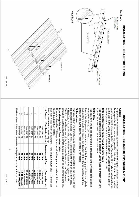
INSTALLATION – COLLECTOR FIXING
Tile Roofs
Metal Roofs
11
Ver 12/2012
INSTALLATION – CYLINDER; P
IPEWORK & PUMP
General
All pipe work within the roof sp
ace must b
e securely clip
ped to prevent vibration.
Drainpipes sh
ould be cle
ar of any possib
le obstru
ction. Hot w
ater pipes m
ust b
e
copper, u
se tig
ht fittin
gs or Teflon only. Pipes sh
ould be fully insulated with min.
13mm wall in
the Zone 5 and 19mm in Zone 6. Use Iso
pipe lagging or sim
ilar
when exposed to UV. Pipe run should be as sh
ort a
s possib
le.
Cold and Hot w
ater supply and cylinder d
rain
The thermal disch
arge rating of all p
rotectio
n valves m
ust b
e greater th
an 7kW
mainly TPR Valve and Cold water re
lief valve
Solar flo
w
The solar flo
w line to the solar pump is co
nnected to the cylinder at th
e bottom
connectio
n marked “Coil C
old”.
Ensure that th
e pump is o
rientated so that it is d
rawing glycol fro
m the cylinder
and pushing it u
p to the panels, th
e directio
n of th
e flo
w is in
dicated with an
arrow on the pump casing. Refer to
page 9 for details.
Solar re
turn
The solar re
turn line fro
m the solar co
llectors is co
nnected to the cylinder at th
e
top connectio
n marked “Coil H
ot”. It sh
ould be shorte
r than solar flo
w pipe.
A Heat Trap is to
be installed to minimise heat lo
sses w
hen system is id
le.
The drop below the normal piping line should be no less th
an 300mm and
extend no less th
an 200mm in length before its re
turn to the normal piping line.
Pipe size guide and flo
w meter ra
tes
Flow rate should be 2-3 litre
/min per panel. A
djust p
ump speed and if d
own to
speed 1, adjust flo
w meter.
Pipe Run = Pipe length of flo
w pipe + Pipe length of re
turn pipe + 1 meter per
bend + 10 meters if tw
o sto
rey up
# Panels
Pipe Run in meters
Recommended Pipe
Flow meter ra
te
1
Less th
an 40
15 mm
2-3 litre
/min
1
More than 40
20 mm
2-3 litre
/min
2
Less th
an 30
15 mm
4-6 litre
/min
2
More than 30
20 mm
4-6 litre
/min
3
Less th
an 25
15 mm
6-8 litre
/min
3
More than 25
20 mm
6-8 litre
/min
4-5
Less th
an 40
20 mm
8-15 litre
/min
4-5
More than 40
25 mm
8-15 litre
/min
6
Less th
an 25
20 mm
12-18 litre
/min
6
More than 25
25 mm
12-18 litre
/min
Maximum head is 6
meters. A
lso refer to
the pump installation instru
ctions.
8

Ver 12/2012
INSTALLATION – TANK; P
IPES & PUMP SETUP
9
Ver 12/2012
INSTALLATION - S
OLAR PANELS
It is important th
at th
e installation of th
e panels w
ill not co
mpromise the
integrity
of th
e roof or th
e building as per G12 AS2. Always use neo-prim
e
washers o
r other in
sulators, to
prevent dissim
ilar m
etal co
rrosion.
Before sta
rting, peel off th
e protectiv
e plastic co
ating fro
m the panels a
s it will
bake onto the surface if e
xposed to the sunlight.
Protect th
e gutter fro
m damage caused by ladders e
tc.
Lift th
e solar panels o
nto the roof one at a tim
e. The best w
ay is to
rest e
ach
panel against th
e gutter w
hile supportin
g it fro
m the ground.
Then pull up the panel onto the roof.
Fixing Methods
Tiled ro
ofs
1.
Allow for th
e top collector upper su
pport a
ngle being positio
ned 3 tile
s down fro
m the rid
ge cap, positio
n the bottom collector su
pport a
ngle 2
meters b
elow where the upper co
llector su
pport a
ngle will b
e.
2.
Slide on the stra
ps to
the bottom collector su
pport a
ngle and fasten the
straps using sta
inless te
k scre
ws to
the rafters u
nderneath the tile
s.
3.
Positio
n panels in
to the bottom collector su
pport a
ngle and begin
connectin
g them together using the inter-co
nnectors. C
onnect a
ll start
pipes and other fittin
gs su
pplied where required.
IMPORTANT: Ensure that fib
ber w
ashers a
re fitte
d to all L type panel
connectio
ns lu
brica
ted with black graphite
4.
Blank off th
e remaining solar panel co
nnectio
ns using a blanking nut and
sensor nut.
5.
Do not place sensor ca
ble if sy
stem remains dry for m
ore than 24hrs
6.
Positio
n the upper co
llector su
pport a
ngle and fasten to the rafters.
7.
Lock the bottom and top collector to
support a
ngles w
ith cla
mps.
Metal R
oofs
The procedure is th
e same as th
e above except th
at th
e top collector su
pport
angles sh
ould be fastened stra
ight onto a roof purlin
Use the same fastening for th
e bottom angle.
Use neoprene washers.
10