user manual - frank's hospital workshop manual affinity iii 2 rev 000 2 intended use the...
TRANSCRIPT

User manual
Affinity® III

© 2000 by Hill-Rom Services, Inc. ALL RIGHTS RESERVED.No part of this text shall be reproduced or transmitted in any form or by anymeans, electronic or mechanical, including photocopying, recording, or byany information or retrieval system without written permission from Hill-RomServices, Inc. (Hill-Rom).
First EditionFirst Printing 2000Printed in the USA
Affinity® is a registered trademark of Hill-Rom, Inc.Beaucoup® is a registered trademark of Huntington Laboratories, Inc.CSA® is a registered trademark of Canadian Standards Association, Inc.Dartex® is a registered trademark of Courtaulds Textiles (Holdings) Limited.EasyGlide™ is a trademark of Hill-Rom, Inc.Galahad® is a registered trademark of Puritan Chemical CompanyHi-Tor® is a registered trademark of Huntington Laboratories, Inc.Hill-Rom® is a registered trademark of Hill-Rom, Inc.Matar® is a registered trademark of Huntington Laboratories, Inc.OneStep™ is a trademark of Hill-Rom, Inc.Quanto® is a registered trademark of Huntington Laboratories, Inc.SideCom® is a registered trademark of Hill-Rom, Inc.Slo-Blo® is a registered trademark of Littelfuse, Inc.Staph-Chek® is a registered trademark of Herculite Products, Inc.Surfacide® is a registered trademark of Walton-March, Inc.Vesphene® II is a registered trademark of E.R. Squibb & Sons, Inc.Virex® is a registered trademark of S.C. Johnson & Son, Inc.
The information contained in this manual is subject to change without notice.Hill-Rom makes no commitment to update or keep current, the informationcontained in this manual.
The only product warranty intended by Hill-Rom is the express, writtenwarranty accompanying the bill of sale to the original purchaser. Hill-Rommakes no other warranty, express or implied, and in particular, makes nowarranty of merchantability or fitness for a particular purpose.To order additional copies of this manual, call (800) 445-3720, and place aparts order for part number usr025.
Revision Letter Pages Affected Date
Original Issue October, 2000

USER MANUAL
TABLE OF CONTENTS
1 Typographical Conventions . . . . . . . . . . . . . . . . . . . . . . . . . . 3
2 Intended Use . . . . . . . . . . . . . . . . . . . . . . . . . . . . . . . . . . . . . . 4
3 Introduction . . . . . . . . . . . . . . . . . . . . . . . . . . . . . . . . . . . . . . . 4
4 Features . . . . . . . . . . . . . . . . . . . . . . . . . . . . . . . . . . . . . . . . . . 44.1 Automatic Tilt . . . . . . . . . . . . . . . . . . . . . . . . . . . . . . . . . . . . . . . . 54.2 Battery Backup . . . . . . . . . . . . . . . . . . . . . . . . . . . . . . . . . . . . . . . 54.3 Bed Controls . . . . . . . . . . . . . . . . . . . . . . . . . . . . . . . . . . . . . . . . . 6
4.3.1 Back Section Lumbar Mattress Control (Optional) . . . . . . . . . 74.3.2 Foot Section . . . . . . . . . . . . . . . . . . . . . . . . . . . . . . . . . . . . . . 84.3.3 Head Section . . . . . . . . . . . . . . . . . . . . . . . . . . . . . . . . . . . . . . 84.3.4 Nurse Call (Optional) . . . . . . . . . . . . . . . . . . . . . . . . . . . . . . . . 94.3.5 Seat Section Mattress Control (Optional) . . . . . . . . . . . . . . . . 94.3.6 TV On/Off (Optional) . . . . . . . . . . . . . . . . . . . . . . . . . . . . . . . 10
4.4 Bed Models . . . . . . . . . . . . . . . . . . . . . . . . . . . . . . . . . . . . . . . . . 104.5 Central Brake and Steer . . . . . . . . . . . . . . . . . . . . . . . . . . . . . . . 104.6 CPR Release . . . . . . . . . . . . . . . . . . . . . . . . . . . . . . . . . . . . . . . . 114.7 Fluid Basin . . . . . . . . . . . . . . . . . . . . . . . . . . . . . . . . . . . . . . . . . . 114.8 Foot Section (Lift-Off or Slide-Off) . . . . . . . . . . . . . . . . . . . . . . . 124.9 OneStep™ Foot Supports . . . . . . . . . . . . . . . . . . . . . . . . . . . . . 144.10 Headboard . . . . . . . . . . . . . . . . . . . . . . . . . . . . . . . . . . . . . . . . . . 154.11 IV Pole . . . . . . . . . . . . . . . . . . . . . . . . . . . . . . . . . . . . . . . . . . . . . 154.12 Labor Grips . . . . . . . . . . . . . . . . . . . . . . . . . . . . . . . . . . . . . . . . . 154.13 Lockout Controls . . . . . . . . . . . . . . . . . . . . . . . . . . . . . . . . . . . . . 164.14 Night Light . . . . . . . . . . . . . . . . . . . . . . . . . . . . . . . . . . . . . . . . . . 164.15 Siderails . . . . . . . . . . . . . . . . . . . . . . . . . . . . . . . . . . . . . . . . . . . . 164.16 Trend-Like Function . . . . . . . . . . . . . . . . . . . . . . . . . . . . . . . . . . 17
5 Optional Features . . . . . . . . . . . . . . . . . . . . . . . . . . . . . . . . . 175.1 Air Support System . . . . . . . . . . . . . . . . . . . . . . . . . . . . . . . . . . . 175.2 Siderail Controls . . . . . . . . . . . . . . . . . . . . . . . . . . . . . . . . . . . . . 18
5.2.1 Built-In SideCom® Communication System Controls(Optional) . . . . . . . . . . . . . . . . . . . . . . . . . . . . . . . . . . . . . . . . 18
6 Accessories . . . . . . . . . . . . . . . . . . . . . . . . . . . . . . . . . . . . . . 196.1 Anesthesia Screen . . . . . . . . . . . . . . . . . . . . . . . . . . . . . . . . . . . 206.2 Arm Board . . . . . . . . . . . . . . . . . . . . . . . . . . . . . . . . . . . . . . . . . . 206.3 EasyGlide™ Calf Supports . . . . . . . . . . . . . . . . . . . . . . . . . . . . . 216.4 Comfort Pad . . . . . . . . . . . . . . . . . . . . . . . . . . . . . . . . . . . . . . . . . 216.5 Disposable Drape . . . . . . . . . . . . . . . . . . . . . . . . . . . . . . . . . . . . 216.6 Foley Hook Kit . . . . . . . . . . . . . . . . . . . . . . . . . . . . . . . . . . . . . . . 22
Affinity IIIRev 000 1

USER MANUAL
6.7 Foot Rest Bar . . . . . . . . . . . . . . . . . . . . . . . . . . . . . . . . . . . . . . . . 226.8 Full Leg Supports . . . . . . . . . . . . . . . . . . . . . . . . . . . . . . . . . . . . 226.9 Instrument Tray . . . . . . . . . . . . . . . . . . . . . . . . . . . . . . . . . . . . . . 236.10 Infusion Support System (ISS) . . . . . . . . . . . . . . . . . . . . . . . . . . 236.11 Labor Bar . . . . . . . . . . . . . . . . . . . . . . . . . . . . . . . . . . . . . . . . . . . 246.12 Oxygen Tank Holder . . . . . . . . . . . . . . . . . . . . . . . . . . . . . . . . . . 246.13 Pendant Control . . . . . . . . . . . . . . . . . . . . . . . . . . . . . . . . . . . . . 246.14 Permanent IV Pole . . . . . . . . . . . . . . . . . . . . . . . . . . . . . . . . . . . . 256.15 Phone and Phone Adaptor . . . . . . . . . . . . . . . . . . . . . . . . . . . . . 256.16 Sheets . . . . . . . . . . . . . . . . . . . . . . . . . . . . . . . . . . . . . . . . . . . . . . 256.17 Siderail Pads . . . . . . . . . . . . . . . . . . . . . . . . . . . . . . . . . . . . . . . . 266.18 Slipcovers (Head and Foot) . . . . . . . . . . . . . . . . . . . . . . . . . . . . 266.19 Wedge Assembly . . . . . . . . . . . . . . . . . . . . . . . . . . . . . . . . . . . . . 26
7 Patient Positioning—Labor and Birth . . . . . . . . . . . . . . . . . 277.1 Upright Position/Voiding Position . . . . . . . . . . . . . . . . . . . . . . . 277.2 Lateral Position (Sims) . . . . . . . . . . . . . . . . . . . . . . . . . . . . . . . . 287.3 Kneeling Position . . . . . . . . . . . . . . . . . . . . . . . . . . . . . . . . . . . . 287.4 Legs Elevated With Foot Mattress . . . . . . . . . . . . . . . . . . . . . . . 287.5 Squatting With The Labor Bar . . . . . . . . . . . . . . . . . . . . . . . . . . 297.6 Pushing With The Labor Bar . . . . . . . . . . . . . . . . . . . . . . . . . . . 297.7 Pushing With The Labor Bar (With Foot Supports) . . . . . . . . . 297.8 Pushing with Calf Supports . . . . . . . . . . . . . . . . . . . . . . . . . . . . 307.9 Epidural/Spinal (Lateral Approach) . . . . . . . . . . . . . . . . . . . . . . 307.10 Epidural (Sitting Approach) . . . . . . . . . . . . . . . . . . . . . . . . . . . . 307.11 Straight Line Trend-Like Positioning . . . . . . . . . . . . . . . . . . . . 317.12 Throne Position (Chair) . . . . . . . . . . . . . . . . . . . . . . . . . . . . . . . 317.13 Birthing Bed Mode . . . . . . . . . . . . . . . . . . . . . . . . . . . . . . . . . . . 317.14 Delivery Table Mode . . . . . . . . . . . . . . . . . . . . . . . . . . . . . . . . . . 327.15 High Modified Trend-Like Position (Birth And Repair) . . . . . . 32
8 Safety Tips . . . . . . . . . . . . . . . . . . . . . . . . . . . . . . . . . . . . . . . 33
9 Cleaning . . . . . . . . . . . . . . . . . . . . . . . . . . . . . . . . . . . . . . . . . 39
10 Product Symbol Definition . . . . . . . . . . . . . . . . . . . . . . . . . . 42
11 Technical Specifications . . . . . . . . . . . . . . . . . . . . . . . . . . . . 45
Affinity III2 Rev 000

USER MANUAL
1 Typographical ConventionsThis manual contains different typefaces and icons designed to improvereadability and increase understanding of its content. Note the followingexamples:
• Standard text—used for regular information.• Boldface text—emphasizes a word or phrase.
• NOTE:—sets apart special information or important instructionclarification.
• The symbol below highlights a WARNING or CAUTION:
Warning and Caution
– A WARNING identifies situations or actions that may affect patientor user safety. Disregarding a warning could result in patient oruser injury.
– A CAUTION points out special procedures or precautions thatpersonnel must follow to avoid equipment damage.
• The symbol below highlights a CAUGHT HAZARD WARNING:
Caught Hazard Warning
• The symbol below highlights a CHEMICAL HAZARD WARNING:
Chemical Hazard Warning
• The symbol below highlights an ELECTRICAL SHOCK HAZARDWARNING:
Electrical Shock Hazard Warning
Affinity IIIRev 000 1

USER MANUAL
2 Intended UseThe Affinity® Three Birthing Bed is intended to be used as a birthing bed forwomen of child bearing age within the acute care Labor and Delivery market.It is not intended for use as a general hospital bed.
3 IntroductionThis manual provides the information required for normal operation of theAffinity® Three Birthing Bed from Hill-Rom. Before operating the Affinity®Three Birthing Bed, be sure that you have read and understood in detail thecontents of this manual. It is important that you read and strictly adhere tothe aspects of safety contained in this manual. Any reference to a side of thebed is from the patients’ view lying in the bed on their back.
4 Features
Affinity III2 Rev 000

USER MANUAL
4.1 Automatic Tilt• As the head section
is raised, the seatsection graduallytilts up from 0° to15°.
• As the head sectionis lowered, the seatsection graduallyreturns to a flatposition.
4.2 Battery BackupThe Affinity® Three Birthing Bed is designed with batterybackup as a standard feature. The battery allows thehilow, foot, and head motors to be activated from thesiderail controls without power being supplied to the bed.In addition, the battery backup powers the nurse callfunction, but it does not power any other bed functions,such as the optional air support system.
Location: The battery backup indicator is located onthe siderail to indicate the batterycondition.
Battery Backup LED Indicators:• ON = Battery status is operational.
• FLASHING = Battery needs charging.
• OFF = Battery is discharged below the level required to runthe motors.
NOTE :If the battery has been completely discharged, it may take up to 36 hours torecharge to operational status.
CAUTION :Remove the battery if the bed will not be in service for extendedperiods of time. Failure to do so could result in damage to the life ofthe battery, or damage to the bed. Contact the appropriatemaintenance personnel, and refer to the Affinity® Three BirthingBed Service Manual (man272).
Battery Backup
Indicators
Affinity IIIRev 000 3

USER MANUAL
To ensure the battery is always charged, plug the bed into the appropriatepower source whenever possible.
Disposal
Power comes from a lead acid battery, which needs to bedisposed of properly according to your local regulations.
For assistance in disposing of the battery, contact yourmaintenance technician.
4.3 Bed ControlsThe Affinity® Three Birthing Bed is electrically operated using siderail orpendant controls. The hilow, head, and foot functions can be operated bybattery backup, if necessary.
Pb
Nurse Control Panel
Patient Control Panel
Affinity III4 Rev 000
USER MANUAL
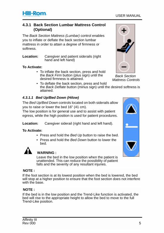
4.3.1 Back Section Lumbar Mattress Control(Optional)
The Back Section Mattress (Lumbar) control enablesyou to inflate or deflate the back section lumbarmattress in order to attain a degree of firmness orsoftness.
Location: Caregiver and patient siderails (righthand and left hand)
To Activate:• To inflate the back section, press and hold
the Back Firm button (plus sign) until thedesired firmness is attained.
• To deflate the back section, press and holdthe Back Deflate button (minus sign) until the desired softness isattained.
4.3.1.1 Bed Up/Bed Down (Hilow)The Bed Up/Bed Down controls located on both siderails allowyou to raise or lower the bed 16" (41 cm).The low position is for general use and to assist with patientegress, while the high position is used for patient procedures.
Location: Caregiver siderail (right hand and left hand).
To Activate:• Press and hold the Bed Up button to raise the bed.• Press and hold the Bed Down button to lower the
bed.
WARNING :Leave the bed in the low position when the patient isunattended. This can reduce the possibility of patientfalls and the severity of any resultant injuries.
NOTE :If the foot section is at its lowest position when the bed is lowered, the bedwill stop at a higher position to ensure that the foot section does not interferewith the base.
NOTE :If the bed is in the low position and the Trend-Like function is activated, thebed will rise to the appropriate height to allow the bed to move to the fullTrend-Like position.
Back SectionMattress Controls
Affinity IIIRev 000 5

USER MANUAL
4.3.2 Foot Section
The Foot Up/Foot Down controls located onboth siderails enable you to raise or lower thefoot section of the bed 9" (23 cm) of travel fromits lowest position.
Location: Caregiver and patient siderails(right hand and left hand)The Foot Up/Down buttons arethe arrows located on the rightside of the label.
To Activate:• Press and hold the Foot Up button
to raise the foot section of the bed.• Press and hold the Foot Down button to lower the foot section of
the bed.
NOTE :If the foot section is at its lowest position when the bed is lowered, the bedwill stop at a higher position to ensure that the foot section does not interferewith the base.
4.3.3 Head Section
The Head Up/Head Down controls located onboth siderails enable you to raise or lower thehead section of the bed. The head section canbe raised to any angle of inclination up to 63°.
Location: Caregiver and patient siderails(right hand and left hand)The Head Up/Down buttons arethe arrows located on the leftside of the label.
To Activate:• Press and hold the Head Up button
to raise the head section of thebed.
• Press and hold the Head Down button to lower the head sectionof the bed.
Foot Section Controls
Head Section Controls
Affinity III6 Rev 000
USER MANUAL
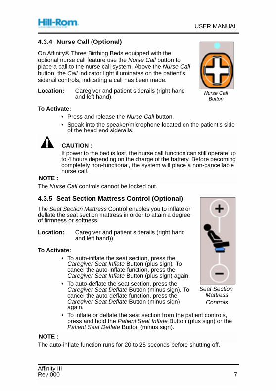
4.3.4 Nurse Call (Optional)
On Affinity® Three Birthing Beds equipped with theoptional nurse call feature use the Nurse Call button toplace a call to the nurse call system. Above the Nurse Callbutton, the Call indicator light illuminates on the patient’ssiderail controls, indicating a call has been made.
Location: Caregiver and patient siderails (right handand left hand).
To Activate:• Press and release the Nurse Call button.• Speak into the speaker/microphone located on the patient’s side
of the head end siderails.
CAUTION :If power to the bed is lost, the nurse call function can still operate upto 4 hours depending on the charge of the battery. Before becomingcompletely non-functional, the system will place a non-cancellablenurse call.
NOTE :The Nurse Call controls cannot be locked out.
4.3.5 Seat Section Mattress Control (Optional)
The Seat Section Mattress Control enables you to inflate ordeflate the seat section mattress in order to attain a degreeof firmness or softness.
Location: Caregiver and patient siderails (right handand left hand)).
To Activate:• To auto-inflate the seat section, press the
Caregiver Seat Inflate Button (plus sign). Tocancel the auto-inflate function, press theCaregiver Seat Inflate Button (plus sign) again.
• To auto-deflate the seat section, press theCaregiver Seat Deflate Button (minus sign). Tocancel the auto-deflate function, press theCaregiver Seat Deflate Button (minus sign)again.
• To inflate or deflate the seat section from the patient controls,press and hold the Patient Seat Inflate Button (plus sign) or thePatient Seat Deflate Button (minus sign).
NOTE :The auto-inflate function runs for 20 to 25 seconds before shutting off.
Nurse CallButton
Seat SectionMattressControls
Affinity IIIRev 000 7

USER MANUAL
4.3.6 TV On/Off (Optional)
The TV on/off button turns on and off the audio for thetelevision and radio.
Location: Patient siderail control panel (right hand andleft hand)
To Activate: Press and release the TV button. The greenindicator light illuminates, and the televisionand radio audio come on. The television andradio volume controls on the patient siderailcontrol panels are now operational.
Mise hors tension : Press and release the TV button. Thegreen indicator light goes off, and the television andradio audio are muted.
4.4 Bed ModelsThe Affinity® Three Birthing Bed is available in two options: the V-Cut or theStraight Edge.
4.5 Central Brake and SteerThe Affinity® Three Birthing Bed is equipped with2-wheel braking and 1-wheel steering.
To Activate:• To brake, press down firmly on the Brake
Pedal (designated by an orange dot). Twocasters will immediately lock into place.Push and pull on the bed to ensure thebrakes are set.
• To release, press firmly on the Steer Pedaluntil both pedals are level (neutral position).
• To steer, press down firmly on the Steer Pedal (designated by a greendot).To release, press firmly on the Brake Pedal until both pedals are level(neutral position).
WARNING :Ensure the brakes are set when transferring a patient to or from theAffinity® Three Birthing Bed. Failure to do so could result in the bedmoving during the transport, which could result in personal injury.
On/OffButtons
V-Cut Straight-Cut
Central Brakeand Steer
Affinity III8 Rev 000

USER MANUAL
4.6 CPR ReleaseThe CPR Release enables the caregiver to save valuable time in anemergency. When activated, the CPR Release automatically lowers thehead and seat section to the flat position, which creates a firm surface tosupport a CPR board.
To Activate: Pull the emergency CPR Release handle on either side of thebed. Release your hand when the head section is down to thelowest position.
4.7 Fluid BasinThe fluid basin is reversible and easily removed for cleaning.
To Remove/Replace:
• Pull the fluid basin straight out.• Slide the basin straight into the holding devices.
Shake the basin gently to ensure it is securely seated.
Emergency CPR ReleaseHandle
Fluid Basin
Affinity IIIRev 000 9

USER MANUAL
4.8 Foot Section (Lift-Off or Slide-Off)
To Remove: The foot section can be removed by using the followingmethods:
If the foot section height can be adjusted:
• Adjust the foot section so that the top of the mattress is about waisthigh.
• Pivot the foot supports laterally.• Grasp and hold the foot section, between the snaps, as close to the
body as possible.• Lift-Off Foot Section: Lift and slide the foot section toward you
(bending your knees) while taking a step backward.• Slide-Off Foot Section: Squeeze the release levers to disengage
the foot section, and slide the section toward you (bending yourknees) while taking a step backward.
• Turn the top of the foot section up and, with the knees bent, place iton the floor with the stand down to hold it upright.
If the foot section is well below the waist and cannot be adjusted:
Affinity III10 Rev 000

USER MANUAL
• Pivot the foot supports laterally.• Approach the foot section from an angle (side or front).• Place one leg forward and one leg back, bending the knees slightly.• Grasp and hold the foot section, between the snaps, as close to the
body as possible.• Lift-Off Foot Section: Lift and slide the foot section toward you while
taking a step backward.• Slide-Off Foot Section: Squeeze the release levers to disengage it,
and slide the foot section toward you while taking a step backward.• Turn the foot section so the stand is down and, with the knees bent,
place it on the floor.
To Install:• Grasp the foot section with both hands.• Position the foot section onto the mounting brackets located on the
bed frame.• Lift-Off Foot Section: While holding the foot section level, lift and
slide it until the latches securely engage and a level surface isachieved.
• Slide-Off Foot Section: While holding the foot section level, push ituntil the latches securely engage and a level surface is achieved.
• Pull on the foot section to ensure that it is locked into position.
Affinity IIIRev 000 11

USER MANUAL
NOTE :If the foot section is not level, this is anindication that it is not locked into position.
• Lift the foot section to the levelposition and push until the latchessecurely engage.
WARNING :The foot section must be fullysecured under the mattress toprovide safe support. Possiblepersonal injury or equipmentdamage could occur.
The foot section must be locked into place.Pull to ensure that the latch is engaged.
4.9 OneStep™ FootSupports
The OneStep™ Foot Supports can besimultaneously positioned up or down,through use of the motor powered footsection yoke. This foot section yokecontrols the overall height up anddown. Each support can beindependently positioned by using themechanical release latches at the endof the foot supports.
To Adjust the Foot Supports:• To position the patient’s legs,
squeeze the release lever androtate the foot support. The footsupport rotates upward andoutward from 0° to 85°.
• To return to the storage position, squeeze the release latch again,and return the supports to the desired position.
The maximum safe working load is 150 lb (68 kg).
Foot Section Not LockedInto Position
OneStep™ Foot Supports
Affinity III12 Rev 000

USER MANUAL
4.10 HeadboardThe headboard includes built-in handleswhich aid in steering control andincrease mobility. The headboardassembly is removable.
To Remove: Grasp the hand holdsfirmly, and lift up.
To Install: Align the headboardsockets with the posts onthe bed frame, and lowerthe headboard until it reston the bed frame.
4.11 IV PoleThe Affinity® Three Birthing Bed comesequipped with one IV pole, stored at thehead end of the bed on the headboard.The IV pole sockets are located at eachcorner of the bed at the head end.
Deploy: Remove the IV pole from theholders. Insert the pole into thedesired socket, and turnclockwise until it drops fully intothe socket and locks into place.
The maximum safe working load is 25 lb(11 kg).
4.12 Labor GripsErgonomically correct labor grips comfortablyaccommodate patients of all sizes. Thehandles are covered with a non-porous, fluidresistant foam that is comfortable for mothersto squeeze.
To Activate: To raise the labor grip, grasp thegrip, and rotate it from under thebed until it clicks in place.To lower, pull the release latch,and lower the grip under thebed.
IV Pole
Built-In Labor Grips
Affinity IIIRev 000 13

USER MANUAL
4.13 Lockout ControlsThe Lockout controls deactivate the hilow, head, andfoot functions on the bed. When a lockout is activated,both the patient and caregiver controls for motorfunctions are locked out.
Location: The Lockout control is located on theframe at the head end of the bed.The Lockout control LED indicator islocated on the caregivers side of bothsiderails.
To Activate: Press the Lockout control switch todeactivate the motors. The lockout LED indicator on thesiderail will light.
Activating the lockout function does not affect the operation of theemergency CPR Release.
4.14 Night LightA photo cell control automatically turns the light on when the room darkensand turns it off when the room gets brighter. The night light does not functionwhen the bed is powered by the battery.
Location: The night light is located on the bottom center of the bedframe.
4.15 SiderailsThe Affinity® Three Birthing Bed has twosiderails, one located on each side of thebed. The head end siderails containcaregiver and patient siderail controls, andcan be adjusted between the upright andlowered positions.
To Adjust:• To raise or lower the siderails, pull
the Siderail Release Latch on thesiderail, and swing the siderail intothe desired position. When raisingthe siderails, you will hear a clickwhen the siderail is securely inplace.
• To store a siderail, lower it completely and push it in under the bedsurface.
WARNING :After changing the position of the siderails, tug on them slightly toensure that they are securely locked in place. Failure to do so couldresult in patient injury.
LED Indicator
Head End Siderail
Affinity III14 Rev 000

USER MANUAL
4.16 Trend-Like FunctionThe Affinity® Three Birthing Bed can achieveup to 8° of Trend-Like positioning. You canactivate the Trend-Like controls at any bedheight. When the bed is in its lowest positionand the Trend-Like function is activated, thebed will rise to the appropriate height in orderto go into the full Trend-Like (8°) position.
To Activate:• To position the sleep surface in a
Trend-Like position, push down on thehandle and guide the bed to thedesired degree, up to 8°.
• To level the sleep surface, pull up on the handle and guide the bed toa level position.
5 Optional Features
5.1 Air Support SystemThe Affinity® Three Birthing Bed features air surface controls (located onboth the outside and inside of the siderail) for both seat and lumbar support.These controls provide improved patient comfort during labor, recovery, andpostpartum while minimizing the cost, maintenance, and labor concernsassociated with the use of overlays.
Seat Support:
Enables the patient to tailor her own comfort level. Provides pelvicsupport to improve practictioner access and visibility during deliveriesand repairs.The firmness or softness of the surface is controlled byincreasing or decreasing the amount of air contained in the air bladder.Patient and staff controls are embedded in both siderails.
Lumbar Support:
Adds varying degrees of back support in the lumbar region to improvepatient comfort both before and after delivery. Fully inflated, the lumbarsupport allows positioning of the patient’s perineum out the V-Cut forexamination and delivery. The maximum lumbar inflation from a flatposition to a full position is 4" (10 cm).
Auxiliary Outlet
The two auxiliary outlets provide electrical power for future upgradeaccessories.
Location: The two 12 V AC (20 watt) auxiliary outlets are located on bothsides of the bed.
Trend-Like Function
Affinity IIIRev 000 15

USER MANUAL
5.2 Siderail Controls
5.2.1 Built-In SideCom® Communication System Controls(Optional)
Every Affinity® Three Birthing Bed with siderail controls is pre-wired toaccommodate the SideCom® Communication System now or in the future.The SideCom® Communication System enables integration of the backlitnurse call, entertainment (radio and TV), and lighting in the siderails. Theoptional Universal TV is also available.
Built-In Siderail Controls
Patient and staff controls are embedded in the siderails on both sides of thebed.
The patient controls are always in full view of the patient, and theinternational graphic symbols provide easy orientation. Patient head and footsection controls are embedded in the inside panel of the siderails (on bothsides of the bed) for the patient’s convenience. Powered operation allows thepatient to respond to her body signals and reduces her dependence on staffassistance for positioning, support, and comfort. These controls includeHead Up/Head Down and Foot Up/Foot Down.
Staff controls are embedded in the outside panel of both siderails. In additionto head and foot section controls, the outside panel contains controls for thehilow operation.
Wood Headboards
The wood headboards includes built-in handles which aid in steering controland increase mobility. The headboard assembly is removable.
To Remove: Grasp the hand holds firmly, and lift up.
To Install: Align the headboard sockets with the posts on the bed frame,and lower the headboard until it rest on the bed frame.
Affinity III16 Rev 000

USER MANUAL
6 Accessories
Table 1. Accessories List
Product Number Description
P9625 Anesthesia screen
P9620 Arm board
P3704 Calf supports, EasyGlide™
P35745A Calf supports, telescoping
P3612 Comfort pad
B7831 Disposable drape
P3623 Foley hook kit
P451 Foot rest bar
P7625C Full leg supports, attached
P7634C Full leg supports, telescoping
P278, P27802 Instrument tray (lift/slide)
P156 ISS mobile stand kit
P159 ISS offset bar
P158 ISS transfer pole
P3613 Labor bar
P276 O2 Tank holder
P5362 Pendant control
P497 Pendant holder
P222101 Permanent IV Pole
P495 Phone
P496 Phone adaptor
SA1528 Sheets, V-cut (compete)
SA1529 Sheets, straight (compete)
SA4885 Sheets, V-cut (two-piece)
SA4586 Sheets, straight (two-piece)
P3705 Siderail pads
P3628B Slipcover, cut head section, air
P3630EA Slipcover, foot section
Affinity IIIRev 000 17

USER MANUAL
6.1 Anesthesia ScreenThe base of the frame slides between the mattress and the frame. Thescreen can be positioned on either side of the bed.
The maximum safe working load is 5 lb (2.3 kg).
6.2 Arm BoardThe arm board is held in place between theframe and mattress. The padding is removablefor cleaning.
The maximum safe working load is 30 lb(14 kg).
P3626B Slipcover, straight edge head section,without air
P3627B Slipcover, straight edge head section, air
P3625B Slipcover, V-cut head section, without air
P3619 Wedge Assembly
Product Number Description
Arm Board
Affinity III18 Rev 000

USER MANUAL
6.3 EasyGlide™ Calf Supports
To Adjust for Use:
• Fold in the hinged mattress.• Rotate the foot supports all the way upward, and outward.• Pull the release latch, and rotate the calf support to the upright
position. The calf supports lock when in the upright position.• Adjust the calf support using the release handle.
NOTE :Check for pressure points, and make appropriate adjustments.For TALL PATIENTS, angle the support downward. For SHORT PATIENTS,angle the support upward.
The maximum safe working load is 60 lb (27 kg).
6.4 Comfort PadThe comfort pad is simply placed on top of the mattress and fitted securelyaround the mattress corners. It rolls up into a compact bundle for storage.
6.5 Disposable DrapeThe full size, absorbent, disposable labor and delivery drape covers theentire seat, foot and lower backrest, and tucks into the fluid basin when theend of the bed is removed. The drape should be placed over the bottomsheet before the patient gets into bed, with the soft, absorbent surface nextto the patient, waterproof side down.
Affinity IIIRev 000 19

USER MANUAL
6.6 Foley Hook KitThe maximum safe working load is 20 lb(9 kg).
6.7 Foot Rest BarThe maximum safe working load is 150 lb(68 kg).
6.8 Full Leg Supports
To Adjust for Use:• Electrically lower the foot section
to the lowest position, with thepatient’s legs on the foot section,before placing her legs into thesupports.
• Both full-leg supports areinterchangeable right and left.
• For leg support installation, placethe rod into the steel socketslocated at the point where the footsection attaches to the yoke.
• Drop them into the sockets, androtate until you hear the supportlock.
• Rotate the supports so that theblack knob faces inboard, toward the patient, and leave the knobloose.
• For large patients, rotate the black knob outboard, away from thepatient.
• Place the patient’s legs into the supports.• Adjust the position by rotating her knees out.• Tighten the black knob.
Foley Hook Kit
Foot Rest Bar
Full Leg Supports
Affinity III20 Rev 000

USER MANUAL
• Raise the foot section electrically to fill in the popliteal space bypushing the Foot Up control. The patient’s legs should be completelysupported.
• Remove the foot section.• Rotate the foot supports up and away from the center of the bed.
NOTE :Check for pressure points, and make appropriate adjustments.For TALL PATIENTS, angle the support downward. For SHORT PATIENTS,angle the support upward.
The maximum safe working load is 60 lb (27 kg).
6.9 Instrument TrayThe instrument tray is available in both a lift-offand slide-off version.
Location: The instrument tray is located atthe foot section of the bed, inthe foot section yoke.
The maximum safe working load is 25 lb(11 kg).
6.10 Infusion Support System (ISS)The ISS System accommodates integration ofthe Hill-Rom’s Infusion Support System forplacement of infusion support devices.
Location: Two locations, on both sides ofthe head section.
The maximum safe working load is 40 lb(18 kg).
Instrument Tray
ISS System
Affinity IIIRev 000 21

USER MANUAL
6.11 Labor BarFor extra support, the labor bar fits into the legsupport sockets between the seat and footcushions.
To Adjust: To raise or lower the bar, use theFoot controls. The bar can beused in either direction fordifferent positions and purposes.
The maximum safe working load is 100 lb(45 kg).
6.12 Oxygen Tank HolderThe oxygen tank holder attaches to the headend of the frame in a vertical position. Theoxygen tank holder accommodates one “E”size oxygen tank with a regulator. Themounting points are located to enable theoxygen tank holder to pivot.
Installation:• Install the mounting bar vertically into a
mounting socket at the head end of thebed frame.
• Place the tank in the holder, and tightenthe holder thumbscrew. Thethumbscrew keeps the oxygen tankfrom rotating in the holder.
Removal:• Loosen the thumbscrew that secures the tank in the holder, and lift
the tank out of the holder.• Lift up on the oxygen tank holder, and remove it from the mounting
sockets.The maximum safe working load is 30 lb (14 kg).
6.13 Pendant ControlThe pendant controls Bed Up/Down, HeadUp/Down, Foot Up/Down.
To Activate: Push the appropriate buttons.
Labor Bar
Oxygen Tank Holder
Pendant Control
Affinity III22 Rev 000

USER MANUAL
6.14 Permanent IV PoleThe Permanent IV Pole, mounted on the headsection frame, enables additional IV bags andpumps to be mounted on either side of thebed.
The maximum safe working load is 25 lb(11 kg).
To Deploy:• Lift the IV pole from its stored position
behind the headboard, and position itstraight up.
• Make sure that the pole drops andlocks into position.
• Raise the upper section of the pole tothe desired height. The IV pole is ready for use.
To Store:• Grasp and hold the upper section of the IV pole. Push the upper
collar down, and lower the upper pole section into the lower polesection.
• Lift the lower section of the IV pole up, and lower the pole down to thestored position behind the headboard. The poles should rest in thestorage slots provided on the bed frame.
CAUTION :Do not mount infusion pumps on the lower section of an IV pole.Interference with head section articulation could result.
6.15 Phone and Phone AdaptorThe patient phone attaches to either siderailby using the adaptor.
6.16 SheetsA sheet set includes pillow case, top, and custom-fitted, bottom sheets.Additionally, the two-piece bottom set is available separately. Before theAffinity® Bed is used by a patient, sheets must be placed over the mattress.
Permanent IV Pole
Phone
Affinity IIIRev 000 23

USER MANUAL
6.17 Siderail PadsThe siderail pads are simply placed over thesiderail for protection against patient injury.
6.18 Slipcovers (Head and Foot)
HeadThe head section slipcover is simply placedover the head section mattress for protectionfrom normal wear and tear and from fluids.
Foot Section Slipcover
The foot section slipcover is simply placedover the foot section mattress for protectionfrom normal wear and tear and from fluids.
6.19 Wedge AssemblyTo quickly convert the V-Cut Seat Section to astraight edge, slide the wedge assembly intothe V-Cut seat section.
Siderail Pads
Head Section Slip Cover
Wedge Assembly
Affinity III24 Rev 000

USER MANUAL
7 Patient Positioning—Labor and BirthNOTE :The Labor and Delivery Drape should be placed over the bottom sheetbefore the patient gets into the bed.
To allow the patient to participate, show her how to operate the controls.
7.1 Upright Position/Voiding Position
• Raise the head of the bed to a comfortable position by pressing theHead Up control.
• Lower the foot section by pressing the Foot Down control.• Place the patient in an upright position.• Place the bed pan backward into the V-Cut on the foot section.• A speciman container may also be used. Slide it between the
mattress and bed frame.• Position the patient out and over the V-Cut having her hold the labor
grips for support.• If the patient’s legs are unstable, position her feet with the soles
together to prevent sliding.
Affinity IIIRev 000 25

USER MANUAL
7.2 Lateral Position (Sims)• With the bed in the lowest position
and the head of the bed adjustedfor the patient’s comfort, positionthe attached calf support with thefoot end pointed toward the head ofthe bed.
• With the patient lying on her leftside, place her right leg in thesupport and lower the foot sectionfor comfort.
• Adjust the support, and tighten thejoint.
7.3 Kneeling Position• Raise the head section of the bed
to the full upright position.• Have the patient kneel on the seat
section and use the head section ofthe bed for support.
7.4 Legs Elevated With FootMattress
This position is useful for various clinicalreasons during antepartum care,postpartum care, and anesthesiaadministration when a patient’s legsrequire elevation. It may also be used forpatient comfort.
To Adjust:• Raise the foot section to its highest
position.• Fold in the hinged part of the foot
section mattress.• Place the patient’s legs on the elevated mattress section.
Affinity III26 Rev 000

USER MANUAL
7.5 Squatting With The Labor Bar• With the bed in the lowest position,
raise the head by pressing theHead Up control, and lower the footsection by pressing the Foot Downcontrol.
• Insert the labor bar into the legsupport sockets, so it angles awayfrom the head of the bed.
• The patient may squat on the seatsection, holding the Labor Bar, orsit with her feet on the foot sectionleaning forward onto the bar.
7.6 Pushing With The Labor Bar• Raise the head of the bed to a
comfortable position by pressingthe Head Up control.
• Insert the labor bar into the supportsockets, so it angles away from thehead of the bed.
• Lower the foot section, if needed,by pressing the Foot Down control.
• Place the patient’s feet on eitherside of the Labor Bar.
• The patient may grip the labor gripsor pull back on her knees.
7.7 Pushing With The Labor Bar(With Foot Supports)
• Raise the head of the bed to acomfortable position by pressingthe Head Up control.
• Remove the foot section.• Place the patient’s feet on the foot
supports and adjust for comfort.• Insert the labor bar into the support
sockets, so it angles away from thehead of the bed.
• The patient may grasp the laborbar where it’s comfortable for her.
Affinity IIIRev 000 27
USER MANUAL
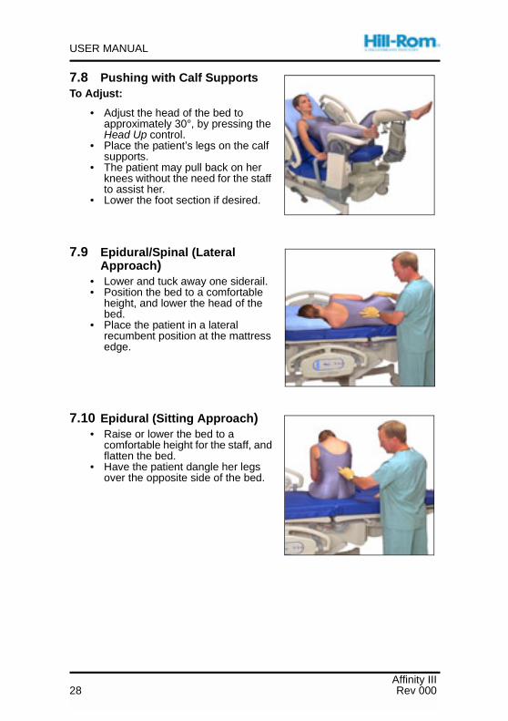
7.8 Pushing with Calf SupportsTo Adjust:
• Adjust the head of the bed toapproximately 30°, by pressing theHead Up control.
• Place the patient’s legs on the calfsupports.
• The patient may pull back on herknees without the need for the staffto assist her.
• Lower the foot section if desired.
7.9 Epidural/Spinal (LateralApproach)
• Lower and tuck away one siderail.• Position the bed to a comfortable
height, and lower the head of thebed.
• Place the patient in a lateralrecumbent position at the mattressedge.
7.10 Epidural (Sitting Approach)• Raise or lower the bed to a
comfortable height for the staff, andflatten the bed.
• Have the patient dangle her legsover the opposite side of the bed.
Affinity III28 Rev 000

USER MANUAL
7.11 Straight Line Trend-LikePositioning
• Pull the CPR Release to lower thehead of the bed to a full flatposition.
• Push down on the Trend-Likehandles (located on either side ofthe bed) and guide the bed to thedesired degree, up to 8°.
• To level the sleep surface, pull upon the handle and guide the bed toa flat position.
General Anesthesia
• In an emergency, position the bed to a comfortable height.• Remove the headboard.• Position the patient for intubation.
7.12 Throne Position (Chair)• Raise the head of the bed to place
the patient in a sitting position.• Pull up the labor grips.• Position the patient’s feet in the
foot supports.• Remove the foot section.• Use the Foot control to raise or
lower the Foot Supports.• Tuck the end of the drape into the
drainage pan and raise the bed toa comfortable height by pressingthe Bed Up control.
7.13 Birthing Bed Mode• Position the patient’s feet in the foot supports. Raise the supports to a
comfortable position.• Pull up the labor grips.• Remove the foot section, and tuck the drape into the drainage pan.• Tilt up the foot support.• Raise the bed to a comfortable height by pressing the Bed Up control,
and position the patient’s perineum out and over the edge of the seatsection.
Affinity IIIRev 000 29
USER MANUAL
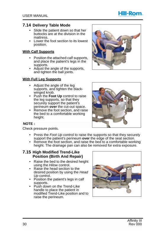
7.14 Delivery Table Mode• Slide the patient down so that her
buttocks are at the division in themattress.
• Lower the foot section to its lowestposition.
With Calf Supports
• Position the attached calf supports,and place the patient’s legs in thesupports.
• Adjust the angle of the supports,and tighten the ball joints.
With Full Leg Supports
• Adjust the angle of the legsupports, and tighten the black-winged knob.
• Push the Foot Up control to raisethe leg supports, so that theysecurely support the patient’sperineum over the cut-out space.
• Remove the foot section, and raisethe bed to a comfortable workingheight.
NOTE :Check pressure points.
• Press the Foot Up control to raise the supports so that they securelysupport the patient’s perineum over the edge of the seat section.
• Remove the foot section, and raise the bed to a comfortable workingheight. The drainage pan can also be removed for extra exposure.
7.15 High Modified Trend-LikePosition (Birth And Repair)
• Raise the bed to the desired heightusing the Hilow control.
• Raise the head section to thedesired position by using the HeadUp control.
• Position the patient’s legs in calfsupports.
• Push down on the Trend-Likehandle to place the patient inmodified Trend-Like position and toraise the perineum.
Affinity III30 Rev 000

USER MANUAL
8 Safety TipsFor over 70 years Hill-Rom has set the standard for quality in patient beds.During this time, with input from many of our customers, we have acquiredthese useful tips.
Bed Positions
WARNING :Make sure the bed is in the low position when the patient isunattended. This can reduce the possibility of patient falls and theseverity of any resultant injuries.
Brakes
WARNING :Always set the brakes when the bed is occupied, except duringpatient transport. To help ensure the bed will not move, push andpull on the bed to check it after the brakes are engaged.
Brakes should always be set when the bed is occupied and especially whenmoving a patient from one surface to another. Patients often use the bed forsupport when getting out of bed and could be injured if the bed unexpectedlymoves. After setting the brakes, push and pull the bed to insure stability.
Fluids
WARNING :Significant fluid spills onto the bed electronics can result in ahazard. If such a spill occurs, unplug the bed and remove it fromservice. Failure to do so could result in personal injury or equipmentdamage.
When massive fluid spills occur on the bed, immediately:
• Unplug the bed from its power source.• Remove the patient from the bed.• Clean the fluid spill from the bed system.• Have maintenance inspect the system completely.
Do not put the bed back into service until it is completely dry, tested, anddetermined to be safe to operate.
Affinity IIIRev 000 31

USER MANUAL
Siderails/Restraints/Patient Monitoring
The siderails should always be in a full upright position and latched when apatient is unattended. When raising the siderails, an audible click indicatesthat the siderails are completely raised and locked in place.
Siderails are intended to be a reminder, not a patient restraining device. Hill-Rom recommends the appropriate medical personnel determine the level ofrestraint necessary to ensure a patient will remain safely in bed. Consult therestraint manufacturer’s instructions for use to verify the correct applicationof each restraining device.
WARNING :Siderails are not intended to be used as restraint devices. Medicalpersonnel should determine the appropriate use of siderails andensure patient safety. Failure to do so could result in patient injury.
1. Develop guidelines for all patients that indicate:
• Which patients may need to be restrained and the appropriaterestraint to utilize.
• The proper method to monitor a patient, whether restrained or not,including time interval, visual check of restraint, etc.
2. Develop training programs for all caregivers concerning theproper use and application of restraints.
3. Maintain the bed at its lowest position whenever a caregiver isnot in the room.
4. Clarify the need for restraint devices to families or guardians.
Electricity
WARNING :Unplug the bed from its power source, and activate the lockoutswitches before cleaning or service. Failure to do so could result inpersonal injury or equipment damage.
Affinity III32 Rev 000

USER MANUAL
Verify that the lockout switch is activated before cleaning or servicing thebed. The battery backup provides power to the bed functions even when thebed is unplugged from its power source.
WARNING :Establish policies and procedures to train and educate your staff onthe risks associated with electrical equipment. Failure to do socould result in personal injury or equipment damage.
WARNING :Significant fluid spills onto the bed electronics can result in ahazard. If such a spill occurs, unplug the bed, and remove it fromservice. Thoroughly clean the bed and allow it to dry, then have thebed checked by service personnel.
CAUTION :Before transporting the bed, ensure that the power cord is stored onthe power cord wrap holder provided on the headboard. Failure todo so could result in equipment damage.
WARNING :Improper use or handling of the power cord may result in damage tothe power cord. If damage has occurred to the power cord or any ofits components, immediately remove the bed from service, andcontact the appropriate maintenance personnel. Failure to do socould result in personal injury or equipment damage.
Use only Hill-Rom power cords as a replacement. Other power cords havenot been investigated for compliance with electrical safety standards for thisproduct.
WARNING :If the integrity of the external protective earth conductor is in doubt,operate the bed from its internal electrical power source. Failure todo so could result in personal injury.
Affinity IIIRev 000 33

USER MANUAL
CAUTION :This device meets all requirements for electromagneticcompatibility per IEC 601-1-2 and the Medical Device Directive andhas been fully tested to such requirements. It is unlikely that theuser will encounter problems with this device because ofinadequate electromagnetic immunity. However, electromagneticimmunity is always relative, and standards are based on anticipatedenvironments of usage. If the user notes unusual device behavior,particularly if such behavior is intermittent and associated withnearby usage of radio or TV transmitters, cell phones, orelectrosurgical equipment, this could be an indication ofelectromagnetic interference. If such behavior occurs, the usershould try moving the interfering equipment further from this device
Policies and procedures must be established to train and educate your staffon the risks associated with electric equipment. It is never prudent ornecessary for personnel to place any part of their body under or betweenmoving parts of the bed. Whenever a bed is being cleaned or serviced, itshould be unplugged from its power source, and the lockout switch shouldbe activated to keep the bed from accidentally operating due to the batterybackup. If service personnel need to get under the bed, the hilow portionmust be blocked up as an added precaution. Refer to the Affinity® ThreeBirthing Bed Service Manual (man272).
Parts and Accessories
Use only Hill-Rom parts and accessories. Do not modify the bed systemwithout authorization from Hill-Rom.
Operating Precautions
WARNING :Do not operate the bed in the presence of flammable gas or vapors.Failure to do so could result in personal injury or equipmentdamage.
WARNING :Use oxygen administering equipment of the nasal, mask, orventilator type only. Do not use the bed with oxygen tents. Failure todo so could result in personal injury or equipment damage.
Affinity III34 Rev 000

USER MANUAL
WARNING :Deactivate the bed functions using the lockout control. Movementof a patient or inadvertent activation of the bed functions by anyoneelse could result in personal injury.
Lockout Controls
Activate the lockout control at the head end of the bed to keep a patient orvisitor from operating the motor function on the siderail controls.
Maintenance
WARNING :Only facility-authorized personnel should perform preventivemaintenance on the Affinity® Three Birthing Bed. Preventivemaintenance performed by unauthorized personnel could result inpersonal injury or equipment damage.
The Affinity® Three Birthing Bed requires an effective maintenance program.We recommend that you perform annual preventive maintenance (PM) andtesting for Joint Commission on Accreditation of Healthcare Organizations(JCAHO). PM and testing not only meet JCAHO requirements but will helpensure a long, operative life for the Affinity® Three Birthing Bed. PM willminimize downtime due to excessive wear. For the preventive maintenanceschedule, refer to the Affinity® Three Birthing Bed Service Manual(man272).
Troubleshooting
WARNING :Only facility-authorized personnel should troubleshoot the Affinity®Three Birthing Bed. Troubleshooting by unauthorized personnelcould result in personal injury or equipment damage.
Always check the battery charge status on the siderail. The bed may not befunctioning due to the battery being drained, and the bed needing to beplugged into its appropriate power source.
Affinity IIIRev 000 35

USER MANUAL
Transport
WARNING :The Affinity® Three Birthing Bed is intended to be used to transportpatients with the foot end of the bed forward. Prior to transport,properly store the power cord to help prevent tripping. Use only theheadboard transport handles to move the bed during transport. Donot transport patients while the bed is in the chair position. Failureto do so could result in personal injury or equipment damage.
WARNING :Make sure that the patient, equipment, and all lines (includingpower cords) are securely placed within the perimeter of the bed forintra-hospital transport. Failure to do so could result in personalinjury or equipment damage.
WARNING :Fully extended IV poles could impact doorways or ceiling fixtures.Lower the poles prior to patient transport. Failure to do so couldresult in personal injury or equipment damage.
WARNING :Be sure to connect the nurse call SideCom® CommunicationSystem cables after transport is complete. Failure to do so couldresult in personal injury.
WARNING :Do not leave the bed exposed to extreme environmental conditionsfor extended periods of time. Possible equipment damage couldoccur.
WARNING :Transport the bed in a low position, and ensure that the bed is nottransported over a side inclination of more than 5°. Failure to do socould result in personal injury or equipment damage.
Affinity III36 Rev 000

USER MANUAL
9 Cleaning
WARNING :Follow the product manufacturer’s instructions. Failure to do socould result in personal injury or equipment damage.
WARNING :Unplug the unit from its power source. Failure to do so could resultin personal injury or equipment damage.
WARNING :Do not expose the unit to excessive moisture. Personal injury orequipment damage could occur.
CAUTION :Do not use harsh cleaners, solvents, or detergents. Equipmentdamage could occur.
General Cleaning
Clean the unit with a lightly dampened cloth and ordinary disinfectants. Donot use excessive liquid.
Steam Cleaning
Do not use any steam cleaning device on the Affinity® Three Birthing Bed.Excessive moisture can damage mechanisms in this unit.
Cleaning Hard to Clean Spots
To remove difficult spots or stains, use standard household cleaners and asoft bristle brush. To loosen heavy, dried-on soil or excreta, you may firstneed to saturate the spot.
Disinfecting
Dilute disinfectants and germicides as specified on the manufacturer’s label.
Affinity IIIRev 000 37

USER MANUAL
Care of Wood Components
Wood is selected for use on beds because of its beauty and warmth. All Hill-Rom wood products are treated with a resin-based sealer and finish thatprovide resistance to abrasion, staining, fluids, and fire. Manydisinfectant/cleansers have a “softening” effect on any painted or finishedsurface if used in high concentrations. Diluted ammonia, mild detergents,and diluted bleach solutions may be used. Clean by wiping a soft dampenedcloth over the surface, followed by wiping with a dry cloth. At no time shoulda wet cloth be allowed to lay on the surface. Any liquid spilled on the surfaceshould be wiped up immediately. Any liquid allowed to lay on the surfaceunattended may damage the finish. For protection of the finish werecommend using a liquid-type furniture polish. Polish about once a month,and wipe off any excess with a soft dry cloth. Have any nicks or scrapesrepaired to prevent water damage.
Mattress Care and Draping
Correct draping technique is essential in preserving the life of the mattress.Drapes must be fluid repellent. The Hill-Rom labor and delivery drapeeffectively covers the lower three quarters of the bedding throughout labor.Additional pads or towels placed under the patient will help prevent fluid fromreaching the edges of the drape. This safeguard keeps the sheets clean anddry while preventing fluid exposure to the mattress.
NOTE :Standard OB packs and paper drapes will not keep the sheets dry.
Repeated soaking of mattress materials will accelerate wear and eventuallydestroy mattress seals, causing fluids to leak into the cushions.
Hill-Rom slipcovers are recommended to help extend the life of the mattress.
NOTE :Mattress damage caused by improper draping and cleaning procedures isnot covered by warranty.
NOTE :Sheets must always be placed over the mattress before the bed is used by apatient.
Affinity III38 Rev 000

USER MANUAL
The following products have been tested by the Herculite Laboratory andhave been found not to have a harmful effect on Dartex®1 fabrics when usedin accordance with manufacturer’s recommended dilution.
1. Dartex® is a registered trademark of Courtaulds Textiles (Holdings) Limited.
Trade Name Type Manufacturer
A33 Quartenary AirwickAbsolute Quartenary Walton-MarchBeaucoup®a
a. Galahad® is a registered trademark of Puritan Chemical Company
Phenolic HuntingtonBlue Chip Quartenary S.C. JohnsonCoverage 256 Quartenary VestalEl Dorado Plus Quartenary Puritan/ChurchillElimstaph Quartenary Walter G. LeggeForward DC Quartenary S.C. JohnsonFrenklin Sentine Quartenary PurexGalahad®b
b. Surfacide® is a registered trademark of Walton-March, Inc.
Phenolic Puritan/Churchill
Hi-Tor®c
c. Virex® is a registered trademark of S.C. Johnson & Son, Inc.
Quartenary HuntingtonInsurance Quartenary VestalLPH Phenolic VestalMatar®d
d. Beaucoup® is a registered trademark of Huntington Laboratories, Inc.
Phenolic HuntingtonOmega Quartenary AirwickQuanto®e
e. Hi-Tor® is a registered trademark of Huntington Laboratories, Inc.
Quartenary HuntingtonSanikleen Quartenary West ChemicalSanmaster III Quartenary Service MasterSurfacide®f
f. Matar® is a registered trademark of Huntington Laboratories, Inc.
Quartenary Walton-MarchTri-Quat Quartenary VestalVesphene®g II
g. Quanto® is a registered trademark of Huntington Laboratories, Inc.
Phenolic Vestal
Virex®h
h. Vesphene® II is a registered trademark of E.R. Squibb & Sons, Inc.
Quartenary S.C. JohnsonDeep Purple N/A N/ABetagone N/A N/A
Affinity IIIRev 000 39

USER MANUAL
10 Product Symbol DefinitionThe following symbols are used on the Affinity® Three Birthing Bed:
Symbol Description
Type B applied part according to EN 60601-1
According to IEC 529
CAUTION: Consult accompanying documents
Conforms to the European Medical DeviceDirective 93/42/EEC
Certified by Underwriters Laboratory in accor-dance with UL2601-1, CAN/CSA C22.2NO.601.1, EN 60601-1, IEC 601-2-38 andIEC 601-1-2.
CPR function—Identifies the release leverthat can be used to manually drop the inclinedhead section, in order that cardiopulmonaryresuscitation can be performed without delay
Lockout control label—The switch in the upposition indicates the lockout control is on.The switch in the down position indicates thelockout control is off (refer to the section titled“Lockout Controls” on page 16 for lockout sta-tus information)
IPX2
Affinity III40 Rev 000

USER MANUAL
Battery charge status (refer to the sectiontitled “Battery Backup” on page 5 for batterystatus information)
Nurse call (refer to the section titled “NurseCall (Optional)” on page 9 for nurse callswitch information)
Lockout control status—when the lockoutcontrol status light is on, the lockout functionis activated.
Identifying mains fuse
Alternating current
Equipotentiality
Safe working load
Symbol Description
= kg
Affinity IIIRev 000 41

USER MANUAL
Electric shock hazard
Keep feet clear of this area. Potential forinjury.
Trend-Like function
Symbol Description
Affinity III42 Rev 000

USER MANUAL
11 Technical Specifications
Table 2. Dimensions for Product P3700
Feature Dimension
Total Length 90" (229 cm)
Length from roller bumpers to break inseat section
61 7/8" (157 cm)
Length from break in the seat section toend of bed
28 1/8" (71 cm)
Maximum Width (siderails stored) 36" (91 cm)
Maximum Width (siderails up) 39" (99 cm)
Maximum Headboard Height 52" (132 cm)
Maximum Siderail Height (without mat-tress)
14¾" (37.47 cm)
Minimum Under-Bed Clearance 5" (13 cm)
Wheel Base 50" (127 cm) x 29" (74 cm)
Mattress Width 35" (89 cm)
Mattress Length 78" (198 cm)
Mattress Thickness (head/seat) 4" (10 cm)
Mattress Thickness (foot) 3" (8 cm)
Detachable Power Cord, IEC 320/inter-face
US, 84" (213 cm)/international,98" (248.9 cm)
Caster Size 6" (15 cm) or 8" (20 cm)
Total Weight 480 lb (218kg) maximum
Affinity IIIRev 000 43

USER MANUAL
Table 3. Specifications for Product P3700
Table 4. Product Identification
Table 5. Environmental Conditions for Transport and Storage
Table 6. Environmental Conditions for Use
Feature Dimension
Head Section Inclination (maximum) 63°
Seat Section Inclination (maximum) 15°
Bed Height Range 18" (46 cm) to 34" (86 cm)
Bed Height Range (with mattress) 22" (56 cm) to 38" (97 cm)
Trend-Like position (maximum) 8°
Bed Lift capacity (maximum safe workingload)
500 lb (227 kg)
Foot Section Lift capacity (maximum) 400 lb (181 kg)
Head Section Lift capacity (maximum) 200 lb (91 kg)
Maximum Height of Seat Section (inTrend-Like position)
40" (102 cm)
Product Number Description
P3700 Affinity® Three Birthing Bed
Condition Range
Temperature -40°F(-40°C) to 158°F (70°C)
Relative humidity 95% non-condensing
Pressure 500 hPa to 1060 hPa
Condition Range
Temperature 59°F (15°C) to 104°F (40°C)ambient temperature
Relative humidity range 10% to 85% non-condensing
Affinity III44 Rev 000

USER MANUAL
Table 7. Mains Power Requirements
Table 8. Fuse Specifications
Table 9. Auxiliary Outlet Power Specifications
Condition Range
Rated voltage 120V AC/230V AC
Power/input 4 A/2 A
Frequency 50/60 Hz
Condition Range
Air system fuse (air system optional) 2 A, 250 V~, 5 x 20 mm, UL198G Fast Acting
Battery fuse 10 A, 32 V~, ATO
Mains fuse (120 V bed model) 4 A, 250 V~, 5 x 20 mm, UL198G Slo-Blo®a or equivalent
a. Slo-Blo® is a registered trademark of Littelfuse, Inc.
Mains fuse (230 V bed model) 2 A, 250 V~, 5 x 20 mm,IEC127 Sheet III, Time Delay
Condition Range
Auxiliary outlets 12V AC, 20 W per outlet, elec-trically isolated from earthground
Affinity IIIRev 000 45

USER MANUAL
Table 10. Classification and StandardsThe Affinity® Three Birthing Bed is designed and manufactured according toequipment classifications and the following standards.
Technical and Quality Assurance Stan-dards
EN 60601-1 and amendmentsUL 2601-1CSA®a C22.2 No. 601.1IEC 60601-2-38IEC 60601-1-2EN ISO 9001 and EN 46001
a. CSA® is a registered trademark of Canadian Standards Association, Inc.
Equipment Classifications per EN60601-1
Class I equipment, internallypowered equipment
Degree of Protection Against ElectricShock of the Applied Part
Type B
Classification according to Directive93/42/EEC
Class I
Degree of Protection Against Ingress ofWater
IPX2
Degree of Protection Against the Pres-ence of Flammable Anaesthetic Mixtures
Ordinary equipment, not for usein a flammable atmosphere
Mode of Operation Continuous operation withintermittent loading, 3 minutesON/30 minutes OFF
Affinity III46 Rev 000

QD5133
France Belgique / België Suisse / Schweiz
Hill-RomBP 14 - Z.I. du Talhouët56330 PluvignerTel : +33 (0)2.97.50.92.12Service Clients : +33 (0)802 01 23 45Fax : +33 (0)2.97.50.92.00
DistribalAdmiral De Boisot Straat 19-212000 AntwerpenTel : +32 32 38 43 15Fax : +32 32 16 06 86
Hill-Rom SAChemin du Vallon 261030 BussignyTel: +41 (0)21 / 706 21 30Fax : +41 (0)21 / 706 21 33e-mail : hrch.info@hill-rom
United Kingdom Deutschland Österreich
Hill-RomClinitron HouseAshby ParkAshby de la ZouchLeicestershire LE65 1JGTel : +44 (0)1530 / 411333Fax : +44 (0)1530 / 411555
Hill-RomKurhessenstrasse 1164546 MörfeldenTel: +49 (0)6105 / 9320Fax : +49 (0)6105 / 932 182
Hill-RomJoh. Bukowansky GmbHBüropark Donau / Haus 8Inkustrasse 1-73400 KlosterneuburgTel: +43 (0)2243 / 28550Fax : +43,(0)2243 / 28550-19e-mail : [email protected]
Nederlands Espãna Italia
Hill-Rom BVHagenweg 1cPostbus 1734130 ED VianenTel : +31 (0)347 / 32 35 32Fax : +31 (0)347 / 32 35 00
Hijo de Jose Mani S.A.C/Roca Humbert n° 3708907 l’Hospitalet de LlobregatTel : +34 93.338.71.11Fax : +34 93.261.06.17
Hill-Rom S.p.A.Via Ambrosoli 620090 RodanoTel : +39 02 / 950541Fax : +39 02 / 95328578
Portugal Ellás Norge
Iberdata Equipamentos, S.A.Rua Dr. Ricardo Jorge, 4Venda-Nova2700-301 AmadoraTel : +351 21 476 8170Fax : +351 21 476 8179e-mail : [email protected]
Patient Care SolutionsChatziioannidis NikolaosG. Iordanidi 2 Str54635 ThessalonikiTel : +30 31 960 303Fax : +30 31 960 087
Avalon MedicalBiscop Gens Nilssongate 50659 OsloTel : +47 23 03 63 70Fax : +47 23 03 63 71
Sverige Danmark International
Medibed ABPO BOX 3035Djursholmsvägen 2918303 TäbyTel : +46 875 67 110Fax : +46 873 26 938e-mail : [email protected]
Gondorf MedicalHolevey 302970 HorsholmTel: +45 455 70 881Fax : +45 455 70 650e-mail : [email protected]
HILL-ROM CO., INC.INTERNATIONAL DEPARTMENT1069 STATE ROUTE 46 EAST, J55BATESVILLE, INDIANA 47006 USATel: +1 812 934 8173Fax : +1 812 934 7191WEBSITE: www.hill-rom.come-mail: [email protected]
F B CH
GB D
E I
P GR
A
N
S DK
NL