user manual emx4e soft starter - aucom hub/product library/soft... · 3.10 power factor correction...
TRANSCRIPT

EMX4e Soft StarterUSER MANUAL
CONTENTS
Contents 1. About This Manual .................................... 3 1.1 Disclaimer ................................................... 3
2. Caution Statements .................................. 4 2.1 Electrical shock risk ................................... 4 2.2 Unexpected Operation ................................ 5 2.3 Avertissements à l'attention des clients
canadiens .................................................... 6
3. System Design .......................................... 8 3.1 Feature List ................................................. 8 3.2 Model Code ................................................. 9 3.3 Model Selection .......................................... 9 3.4 Current Ratings ........................................ 10 3.5 Dimensions and Weights ......................... 12 3.6 Physical Installation ................................. 13 3.7 Accessories ............................................... 13 3.8 Main Contactor ......................................... 14 3.9 Circuit Breaker ......................................... 14 3.10 Power Factor Correction ......................... 15 3.11 Short Circuit Protection Devices (SCPD) 15 3.12 IEC Coordination with Short Circuit
Protection Devices .................................... 16 3.13 UL Coordination with Short Circuit
Protection Devices .................................... 17 3.14 Fuse Selection for Type 2 Coordination .. 20 3.15 Specifications ............................................ 21 3.16 Disposal Instructions ............................... 22
4. Installation .............................................. 23 4.1 Command Source ..................................... 23 4.2 Setup Procedure Overview ...................... 23 4.3 Inputs ......................................................... 24 4.4 Outputs ...................................................... 26 4.5 Control Voltage ......................................... 27 4.6 Power Terminations ................................. 28 4.7 Typical Installation .................................... 30 4.8 Quick Setup ............................................... 31
5. Setup Tools ............................................. 32 5.1 Command Source ..................................... 32 5.2 Commissioning ......................................... 32 5.3 Run Simulation ......................................... 33 5.4 Load/Save Settings ................................... 34 5.5 USB Save & Load ...................................... 34
5.6 Network Address....................................... 36 5.7 Digital I/O State .......................................... 37 5.8 Analog I/O State ......................................... 37 5.9 Serial Number & Rating ........................... 37 5.10 Software Versions ..................................... 38 5.11 Thermistor Reset ...................................... 38 5.12 Reset Thermal Model ............................... 38
6. Logs ......................................................... 39 6.1 Event Log ................................................... 39 6.2 Counters .................................................... 39
7. Keypad and Feedback ............................. 40 7.1 The Keypad ................................................ 40 7.2 Remote Keypad ......................................... 41 7.3 Starter status LEDs ................................... 41 7.4 Displays ...................................................... 42
8. Operation ................................................ 44 8.1 Start, Stop and Reset Commands............ 44 8.2 Command Override ................................... 44 8.3 Emergency Mode ...................................... 44 8.4 Auxiliary Trip .............................................. 45 8.5 Typical Control Methods ........................... 45 8.6 Soft Start Methods .................................... 47 8.7 Stop Methods ............................................. 49
9. Programmable Parameters .................. 51 9.1 Programming Menu ................................. 51 9.2 Altering Parameter Values ....................... 51 9.3 Adjustment Lock ....................................... 51 9.4 Parameter List .......................................... 52 9.5 1 Motor Details .......................................... 57 9.6 2 Motor Start/Stop ..................................... 58 9.7 5 Protection Levels .................................... 60 9.8 6 Protection Action .................................... 61 9.9 7 Inputs ....................................................... 64 9.10 8 Relay Outputs.......................................... 66 9.11 9 Analog Output ......................................... 69 9.12 10 Display ................................................... 69 9.13 11 Communications Adapter .................... 72 9.14 12 Pump Input Configuration ................... 75 9.15 13 Flow Protection .................................... 78 9.16 14 Pressure Protection ............................. 78 9.17 15 Pressure Control .................................. 80
710-18433-00A EMX4e User Manual 1

CONTENTS
9.18 16 Depth Protection .................................. 81 9.19 17 Thermal Protection ............................. 81 9.20 20 Advanced .............................................. 82
10. Application Examples ............................. 83 10.1 Smart Card - Pump Protection ............... 83 10.2 Smart Card - Level Controlled Pump
Activation ................................................... 85
11. Troubleshooting ..................................... 87 11.1 Protection Responses .............................. 87 11.2 Trip Messages ........................................... 87 11.3 General Faults .......................................... 94
2 EMX4e User Manual 710-18433-00A
ABOUT THIS MANUAL
1. About This Manual
WARNING Indicates a hazard that may cause personal injury or death.
CAUTION Indicates a hazard that may damage the equipment or installation.
NOTE Provides helpful information.
1.1 Disclaimer The examples and diagrams in this manual are included solely for illustrative purposes.
The information contained in this manual is subject to change at any time and without prior notice. In no event will responsibility or liability be accepted for direct, indirect or consequential damages resulting from the use or application of this equipment.
© 2016 AuCom Electronics Ltd. All Rights Reserved. As AuCom is continuously improving its products it reserves the right to modify or change the
specification of its products at any time without notice. The text, diagrams, images and any other literary or artistic works appearing in this document are protected by copyright. Users may copy some of the material for their personal reference but may not copy or use material for any other
purpose without the prior consent of AuCom Electronics Ltd. AuCom endeavours to ensure that the information contained in this document including images is correct but does not accept any
liability for error, omission or differences with the finished product.
710-18433-00A EMX4e User Manual 3
CAUTION STATEMENTS
2. Caution Statements Caution Statements cannot cover every potential cause of equipment damage but can highlight common causes of damage. It is the installer's responsibility to read and understand all instructions in this manual prior to installing, operating or maintaining the equipment, to follow good electrical practice including applying appropriate personal protective equipment and to seek advice before operating this equipment in a manner other than as described in this manual.
NOTE The EMX4e soft starter is not user serviceable. The unit should only be serviced by authorised service personnel. Unauthorised tampering with the unit will void the product warranty.
2.1 Electrical shock risk
WARNING – ELECTRICAL SHOCK RISK The voltages present in the following locations can cause severe electric shock and may be lethal:
• AC supply cables and connections • Output cables and connections
Many internal parts of the starter
The AC supply must be disconnected from the starter using an approved isolation device before any cover is removed from the starter or before any servicing work is performed.
SHORT CIRCUIT The EMX4e is not short circuit proof. After severe overload or short circuit, the operation of the EMX4e should be fully tested by an authorised service agent.
GROUNDING AND BRANCH CIRCUIT PROTECTION It is the responsibility of the user or person installing the EMX4e to provide proper grounding and branch circuit protection according to local electrical safety codes.
FOR YOUR SAFETY • The STOP function of the soft starter does not isolate dangerous voltages
from the output of the starter. The soft starter must be disconnected by an approved electrical isolation device before accessing electrical connections.
4 EMX4e User Manual 710-18433-00A

CAUTION STATEMENTS
• Soft starter protection features apply to motor protection only. It is the user’s responsibility to ensure safety of personnel operating machinery.
• The soft starter is a component designed for integration within an electrical system; it is therefore the responsibility of the system designer/user to ensure the system is safe and designed to comply with relevant local safety standards.
2.2 Unexpected Operation
WARNING – ACCIDENTAL STARTS In some installations, accidental starts may pose an increased risk to safety of personnel or damage to the machines being driven. In such cases, it is recommended that the power supply to the soft starter is fitted with an isolating switch and a circuit-breaking device (eg power contactor) controllable through an external safety system (eg emergency stop, fault detector).
WARNING – STARTER MAY START OR STOP UNEXPECTEDLY The EMX4e will respond to control commands from various sources, and could start or stop unexpectedly. Always disconnect the soft starter from mains voltage before accessing the starter or load.
WARNING – DISCONNECT MAINS BEFORE ACCESSING STARTER OR LOAD The soft starter has built-in protections which can trip the starter in the event of faults and thus stop the motor. Voltage fluctuations, power cuts and motor jams may also cause the motor to trip.
The motor could restart after the causes of shutdown are rectified, which may be dangerous for personnel. Always disconnect the soft starter from mains voltage before accessing the starter or load.
CAUTION – MECHANICAL DAMAGE FROM UNEXPECTED RESTART The motor could restart after the causes of shutdown are rectified, which may be dangerous for certain machines or installations. In such cases, it is essential that appropriate arrangements are made against restarting after unscheduled stops of the motor.
710-18433-00A EMX4e User Manual 5

CAUTION STATEMENTS
2.3 Avertissements à l'attention des clients canadiens
AVERTISSEMENT L'icône AVERTISSEMENT ci-contre signale les informations concernant des risques pouvant entraîner des blessures graves, voire mortelles. Pour votre sécurité, veuillez consulter les avertissements sur cette page ou demander une copie du présent manuel en français auprès de votre distributeur local.
AVERTISSEMENT – RISQUE DE CHOC ÉLECTRIQUE Les zones suivantes sont soumises à des tensions pouvant provoquer des risques de chocs électriques graves, voire mortels :
• Raccordement et câbles d'alimentation AC • Câbles et raccordements de sortie • De nombreuses pièces internes du démarreur
L'alimentation AC doit être déconnectée du démarreur au moyen d'un dispositif d'isolation agréé avant de retirer des capots ou avant de procéder à des travaux d'entretien.
PAR SÉCURITÉ • La fonction STOP du démarreur progressif n'isole pas des tensions
dangereuses de la sortie du démarreur. Le démarreur progressif doit être déconnecté par un dispositif d'isolement électrique approprié avant d'accéder aux connexions électriques.
• Les fonctions de protection du démarreur progressif ne concernent que la protection du moteur. Il relève de la responsabilité de l'utilisateur d'assurer la sécurité des personnes travaillant sur les machines.
• Le démarreur progressif est un appareil conçu pour s'intégrer dans un système électrique ; il relève donc de la responsabilité du concepteur ou de l'utilisateur de veiller à ce que ce système soit sûr et conçu selon les normes de sécurité locales en vigueur.
AVERTISSEMENT – DÉMARRAGES ACCIDENTELS Dans certaines installations, des démarrages accidentels peuvent provoquer un risque supplémentaire pour la sécurité des personnes ou endommager les machines contrôlées. Dans de tels cas, il est recommandé de doter l'alimentation du démarreur progressif d'un interrupteur d'isolement et d'un coupe-circuit (par exemple, un disjoncteur) contrôlable à partir d'un système de sécurité externe (par exemple, un arrêt d'urgence, un détecteur de défaut).
6 EMX4e User Manual 710-18433-00A
CAUTION STATEMENTS
AVERTISSEMENT – LE DÉMARREUR PEUT DÉMARRER OU S'ARRÊTER À TOUT MOMENT Le EMX4e répond aux commandes de contrôle de différentes origines et peut par conséquent démarrer ou s'arrêter à tout moment. Toujours déconnecter le démarreur de la tension secteur avant d'accéder au démarreur ou à la charge.
AVERTISSEMENT – DÉCONNECTER L'ALIMENTATION PRINCIPALE AVANT D'ACCÉDER AU DÉMARREUR OU À LA CHARGE Le démarreur progressif comporte des protections intégrées qui peuvent déclencher des mises en sécurité dans l'éventualité de défauts et ainsi arrêter le moteur. Des fluctuations de tension, des coupures d'alimentation et des blocages du moteur peuvent produire des mises en sécurité de celui-ci.
Le moteur pourrait redémarrer une fois que les causes de l'arrêt ont été résolues, ce qui pourrait mettre en danger le personnel. Toujours déconnecter le démarreur de la tension secteur avant d'accéder au démarreur ou à la charge.
AVERTISSEMENT Ne pas appliquer la tension du secteur au démarreur tant que tout le câblage n'est pas terminé.
AVERTISSEMENT Toujours appliquer la tension de commande avant (ou en même temps que) la tension secteur.
AVERTISSEMENT Lors du raccordement du EMX4e en connexion 6 fils, toujours installer un contacteur principal ou un disjoncteur magnéto-thermique à bobine de déclenchement.
710-18433-00A EMX4e User Manual 7
SYSTEM DESIGN
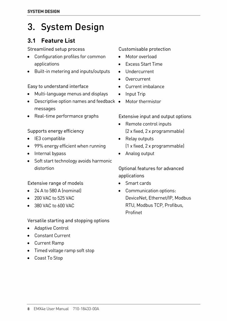
3. System Design 3.1 Feature List Streamlined setup process • Configuration profiles for common
applications • Built-in metering and inputs/outputs Easy to understand interface • Multi-language menus and displays • Descriptive option names and feedback
messages • Real-time performance graphs Supports energy efficiency • IE3 compatible • 99% energy efficient when running • Internal bypass • Soft start technology avoids harmonic
distortion Extensive range of models • 24 A to 580 A (nominal) • 200 VAC to 525 VAC • 380 VAC to 600 VAC Versatile starting and stopping options • Adaptive Control • Constant Current • Current Ramp • Timed voltage ramp soft stop • Coast To Stop
Customisable protection • Motor overload • Excess Start Time • Undercurrent • Overcurrent • Current imbalance • Input Trip • Motor thermistor Extensive input and output options • Remote control inputs
(2 x fixed, 2 x programmable) • Relay outputs
(1 x fixed, 2 x programmable) • Analog output Optional features for advanced applications • Smart cards • Communication options:
DeviceNet, Ethernet/IP, Modbus RTU, Modbus TCP, Profibus, Profinet
8 EMX4e User Manual 710-18433-00A
SYSTEM DESIGN
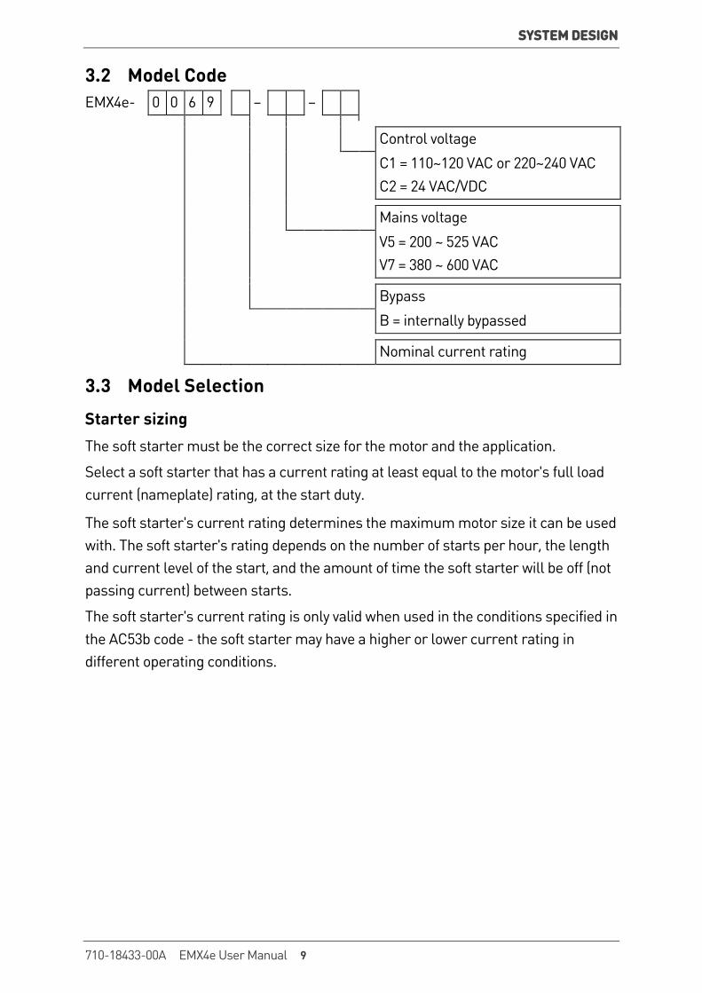
3.2 Model Code EMX4e- 0 0 6 9 – –
Control voltage C1 = 110~120 VAC or 220~240 VAC
C2 = 24 VAC/VDC
Mains voltage V5 = 200 ~ 525 VAC
V7 = 380 ~ 600 VAC
Bypass B = internally bypassed
Nominal current rating
3.3 Model Selection
Starter sizing The soft starter must be the correct size for the motor and the application.
Select a soft starter that has a current rating at least equal to the motor's full load current (nameplate) rating, at the start duty.
The soft starter's current rating determines the maximum motor size it can be used with. The soft starter's rating depends on the number of starts per hour, the length and current level of the start, and the amount of time the soft starter will be off (not passing current) between starts.
The soft starter's current rating is only valid when used in the conditions specified in the AC53b code - the soft starter may have a higher or lower current rating in different operating conditions.
710-18433-00A EMX4e User Manual 9
SYSTEM DESIGN
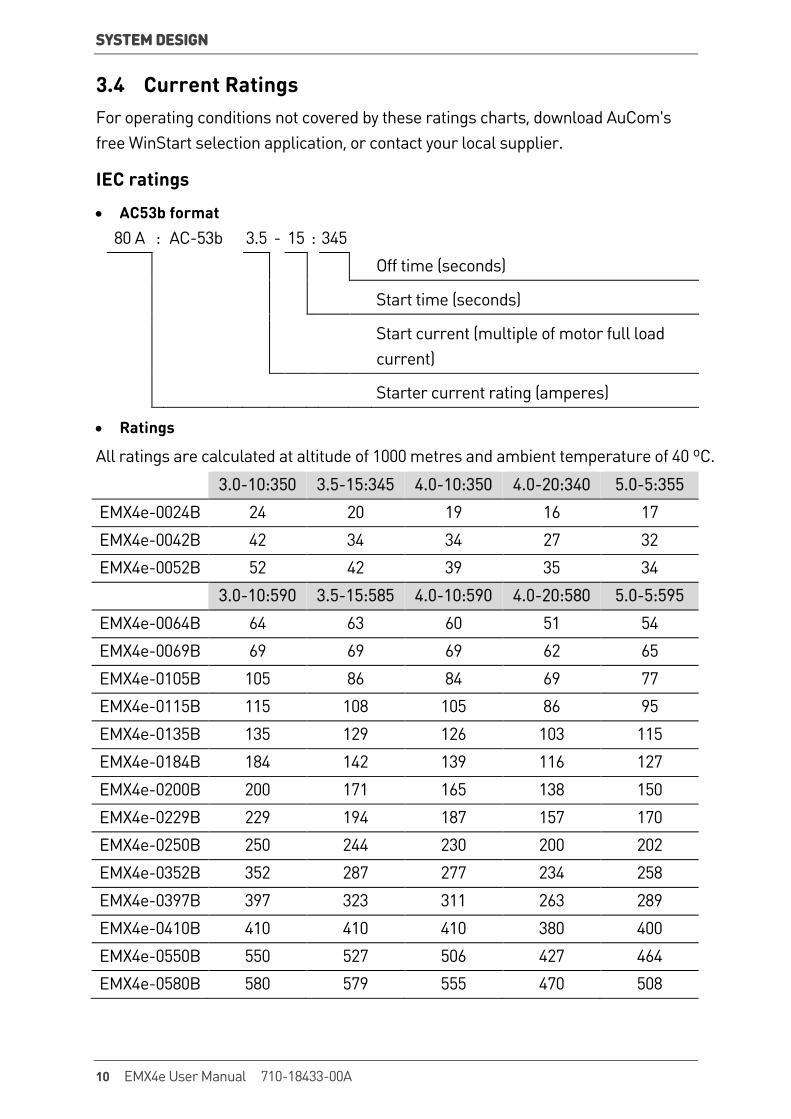
3.4 Current Ratings For operating conditions not covered by these ratings charts, download AuCom's free WinStart selection application, or contact your local supplier.
IEC ratings
• AC53b format 80 A : AC-53b 3.5 - 15 : 345 Off time (seconds)
Start time (seconds)
Start current (multiple of motor full load current)
Starter current rating (amperes)
• Ratings
All ratings are calculated at altitude of 1000 metres and ambient temperature of 40 ºC.
3.0-10:350 3.5-15:345 4.0-10:350 4.0-20:340 5.0-5:355
EMX4e-0024B 24 20 19 16 17
EMX4e-0042B 42 34 34 27 32
EMX4e-0052B 52 42 39 35 34
3.0-10:590 3.5-15:585 4.0-10:590 4.0-20:580 5.0-5:595
EMX4e-0064B 64 63 60 51 54
EMX4e-0069B 69 69 69 62 65
EMX4e-0105B 105 86 84 69 77
EMX4e-0115B 115 108 105 86 95
EMX4e-0135B 135 129 126 103 115
EMX4e-0184B 184 142 139 116 127
EMX4e-0200B 200 171 165 138 150
EMX4e-0229B 229 194 187 157 170
EMX4e-0250B 250 244 230 200 202
EMX4e-0352B 352 287 277 234 258
EMX4e-0397B 397 323 311 263 289
EMX4e-0410B 410 410 410 380 400
EMX4e-0550B 550 527 506 427 464
EMX4e-0580B 580 579 555 470 508
10 EMX4e User Manual 710-18433-00A
SYSTEM DESIGN
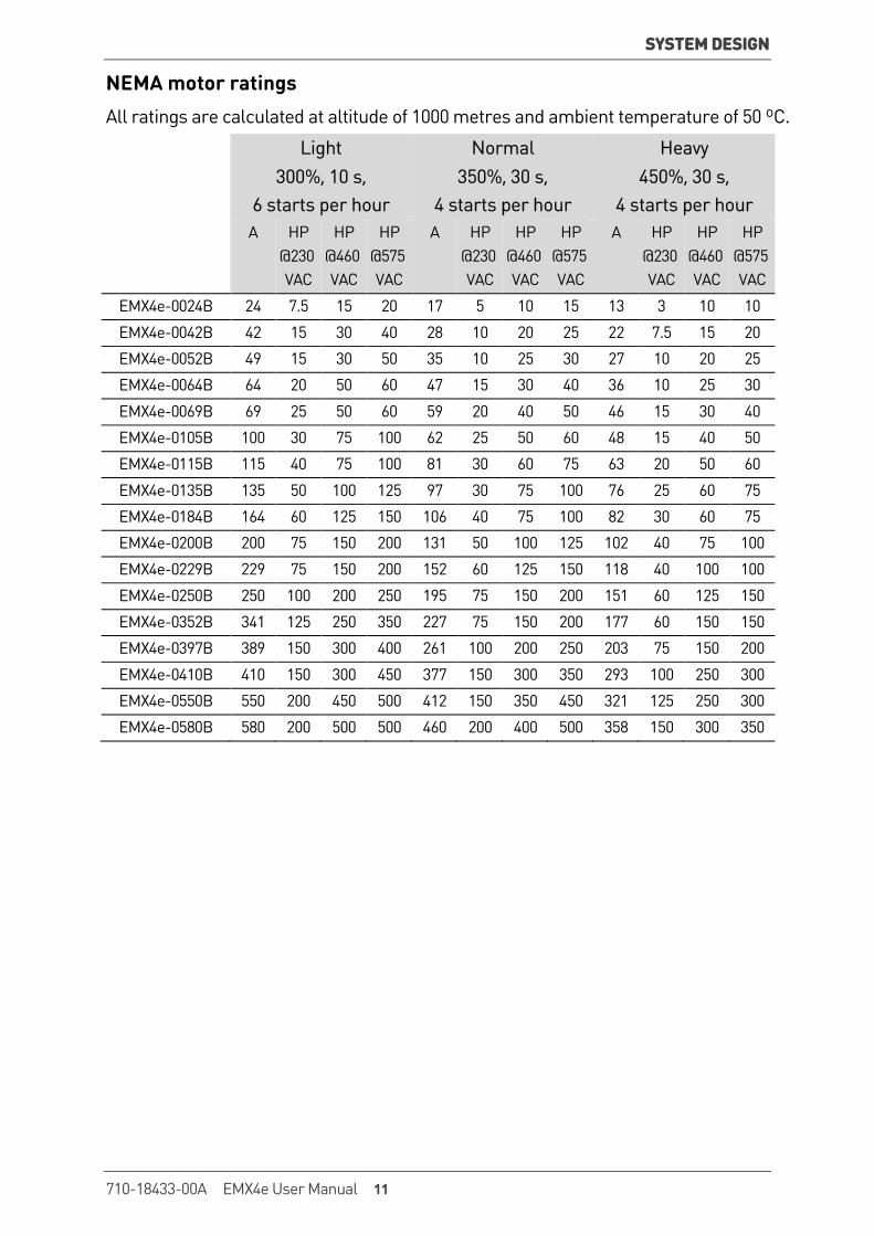
NEMA motor ratings All ratings are calculated at altitude of 1000 metres and ambient temperature of 50 ºC.
Light 300%, 10 s,
6 starts per hour
Normal 350%, 30 s,
4 starts per hour
Heavy 450%, 30 s,
4 starts per hour A HP
@230 VAC
HP @460 VAC
HP @575 VAC
A HP @230 VAC
HP @460 VAC
HP @575 VAC
A HP @230 VAC
HP @460 VAC
HP @575 VAC
EMX4e-0024B 24 7.5 15 20 17 5 10 15 13 3 10 10
EMX4e-0042B 42 15 30 40 28 10 20 25 22 7.5 15 20
EMX4e-0052B 49 15 30 50 35 10 25 30 27 10 20 25
EMX4e-0064B 64 20 50 60 47 15 30 40 36 10 25 30
EMX4e-0069B 69 25 50 60 59 20 40 50 46 15 30 40
EMX4e-0105B 100 30 75 100 62 25 50 60 48 15 40 50
EMX4e-0115B 115 40 75 100 81 30 60 75 63 20 50 60
EMX4e-0135B 135 50 100 125 97 30 75 100 76 25 60 75
EMX4e-0184B 164 60 125 150 106 40 75 100 82 30 60 75
EMX4e-0200B 200 75 150 200 131 50 100 125 102 40 75 100
EMX4e-0229B 229 75 150 200 152 60 125 150 118 40 100 100
EMX4e-0250B 250 100 200 250 195 75 150 200 151 60 125 150
EMX4e-0352B 341 125 250 350 227 75 150 200 177 60 150 150
EMX4e-0397B 389 150 300 400 261 100 200 250 203 75 150 200
EMX4e-0410B 410 150 300 450 377 150 300 350 293 100 250 300
EMX4e-0550B 550 200 450 500 412 150 350 450 321 125 250 300
EMX4e-0580B 580 200 500 500 460 200 400 500 358 150 300 350
710-18433-00A EMX4e User Manual 11
SYSTEM DESIGN
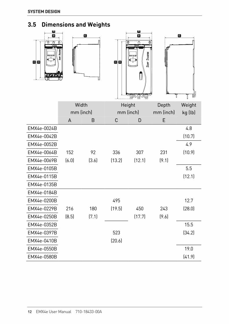
3.5 Dimensions and Weights A
B
C D
E
A
B
C D
E
1704
3.B
Width mm (inch)
Height mm (inch)
Depth mm (inch)
Weight kg (lb)
A B C D E
EMX4e-0024B 4.8
EMX4e-0042B (10.7)
EMX4e-0052B 4.9
EMX4e-0064B 152 92 336 307 231 (10.9)
EMX4e-0069B (6.0) (3.6) (13.2) (12.1) (9.1)
EMX4e-0105B 5.5
EMX4e-0115B (12.1)
EMX4e-0135B
EMX4e-0184B
EMX4e-0200B 495 12.7
EMX4e-0229B 216 180 (19.5) 450 243 (28.0)
EMX4e-0250B (8.5) (7.1) (17.7) (9.6)
EMX4e-0352B 15.5
EMX4e-0397B 523 (34.2)
EMX4e-0410B (20.6)
EMX4e-0550B 19.0
EMX4e-0580B (41.9)
12 EMX4e User Manual 710-18433-00A

SYSTEM DESIGN
3.6 Physical Installation
DD
1704
4.B
C
C
BA
Between starters Solid surfaces A B C D
> 100 mm (3.9 inch) > 10 mm (0.4 inch) > 100 mm (3.9 inch) > 10 mm (0.4 inch)
3.7 Accessories
Expansion Cards The EMX4e offers expansion cards for users requiring additional inputs and outputs or advanced functionality. Each EMX4e can support a maximum of one expansion card.
• Smart Card
The smart card has been designed to support integration with pumping applications and provides the following additional inputs and outputs:
• 3 x digital inputs • 3 x 4-20 mA transducer inputs • 1 x RTD input • 1 x USB-B port • Remote keypad connector
• Communication Expansion Cards
EMX4e soft starters support network communication via easy-to-install communications expansion cards. Each communications card includes a remote keypad connector port.
Available protocols:
DeviceNet, Ethernet/IP, Modbus RTU, Modbus TCP, Profibus, Profinet.
710-18433-00A EMX4e User Manual 13
SYSTEM DESIGN
Remote Keypad EMX4e starters can be used with a remote keypad, mounted up to 3 metres away from the starter. Each expansion card includes a keypad connection port, or a dedicated keypad connector card is available.
Finger Guard Kit Finger guards may be specified for personnel safety. Finger guards fit over the soft starter terminals to prevent accidental contact with live terminals. Finger guards provide IP20 protection when used with cable of diameter 22 mm or greater.
Finger guards are compatible with models EMX4e-0184B ~ EMX4e-0580B.
WinMaster Starter Management Software WinMaster PC software can provide real-time or offline management of all AuCom soft starters.
• For real-time management in a network of up to 99 starters, WinMaster must connect to the EMX4e via a Modbus TCP or Modbus RTU card. WinMaster can monitor, control and program the starter across the network.
• For offline management, a configuration file generated in WinMaster can be loaded into the starter via the USB port.
3.8 Main Contactor A main contactor is recommended to protect the soft starter from voltage disturbances on the network, while stopped. Select a contactor with an AC3 rating greater than or equal to the full load current rating of the connected motor.
Use the main contactor output (33, 34) to control the contactor.
3.9 Circuit Breaker A shunt trip circuit breaker may be used instead of a main contactor to isolate the motor circuit in the event of a soft starter trip. The shunt trip mechanism must be powered from the supply side of the circuit breaker or from a separate control supply.
14 EMX4e User Manual 710-18433-00A

SYSTEM DESIGN
3.10 Power Factor Correction If power factor correction is used, a dedicated contactor should be used to switch in the capacitors.
To use the EMX4e to control power factor correction, connect the PFC contactor to a programmable relay set to Run. When the motor reaches full speed, the relay will close and power factor correction will be switched in.
CAUTION Power factor correction capacitors must be connected to the input side of the soft starter. Connecting power factor correction capacitors to the output side will damage the soft starter.
3.11 Short Circuit Protection Devices (SCPD) Fuses may be installed to protect the soft starter or the installation.
Type 1 Coordination Type 1 coordination requires that, in the event of a short circuit on the output side of a soft starter, the fault must be cleared without risk of injury to personnel. There is no requirement that the soft starter must remain operational after the fault.
HRC fuses (such as Ferraz/Mersen AJT fuses) can be used for Type 1 coordination according to IEC 60947-4-2 standard.
Type 2 Coordination Type 2 coordination requires that in the event of a short circuit on the output side of a soft starter, the fault must be cleared without risk of injury to personnel or damage to the soft starter.
Semiconductor fuses for Type 2 circuit protection are additional to HRC fuses or MCCBs that form part of the motor branch circuit protection.
CAUTION Integral solid state short circuit protection does not provide branch circuit protection. Branch circuit protection must be provided in accordance with the National Electrical Code and any additional local codes.
710-18433-00A EMX4e User Manual 15
SYSTEM DESIGN
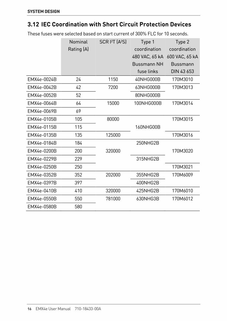
3.12 IEC Coordination with Short Circuit Protection Devices These fuses were selected based on start current of 300% FLC for 10 seconds.
Nominal Rating (A)
SCR I2T (A2S) Type 1 coordination
480 VAC, 65 kA Bussmann NH
fuse links
Type 2 coordination
600 VAC, 65 kA Bussmann DIN 43 653
EMX4e-0024B 24 1150 40NHG000B 170M3010
EMX4e-0042B 42 7200 63NHG000B 170M3013
EMX4e-0052B 52 80NHG000B
EMX4e-0064B 64 15000 100NHG000B 170M3014
EMX4e-0069B 69
EMX4e-0105B 105 80000 170M3015
EMX4e-0115B 115 160NHG00B
EMX4e-0135B 135 125000 170M3016
EMX4e-0184B 184 250NHG2B
EMX4e-0200B 200 320000 170M3020
EMX4e-0229B 229 315NHG2B
EMX4e-0250B 250 170M3021
EMX4e-0352B 352 202000 355NHG2B 170M6009
EMX4e-0397B 397 400NHG2B
EMX4e-0410B 410 320000 425NHG2B 170M6010
EMX4e-0550B 550 781000 630NHG3B 170M6012
EMX4e-0580B 580
16 EMX4e User Manual 710-18433-00A
SYSTEM DESIGN
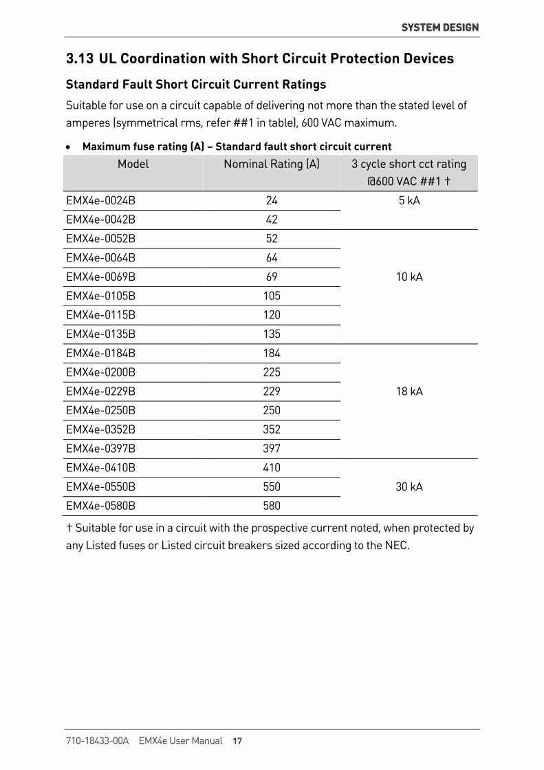
3.13 UL Coordination with Short Circuit Protection Devices
Standard Fault Short Circuit Current Ratings Suitable for use on a circuit capable of delivering not more than the stated level of amperes (symmetrical rms, refer ##1 in table), 600 VAC maximum.
• Maximum fuse rating (A) – Standard fault short circuit current Model Nominal Rating (A) 3 cycle short cct rating
@600 VAC ##1 †
EMX4e-0024B 24 5 kA
EMX4e-0042B 42
EMX4e-0052B 52
EMX4e-0064B 64
EMX4e-0069B 69 10 kA
EMX4e-0105B 105
EMX4e-0115B 120
EMX4e-0135B 135
EMX4e-0184B 184
EMX4e-0200B 225
EMX4e-0229B 229 18 kA
EMX4e-0250B 250
EMX4e-0352B 352
EMX4e-0397B 397
EMX4e-0410B 410
EMX4e-0550B 550 30 kA
EMX4e-0580B 580
† Suitable for use in a circuit with the prospective current noted, when protected by any Listed fuses or Listed circuit breakers sized according to the NEC.
710-18433-00A EMX4e User Manual 17
SYSTEM DESIGN
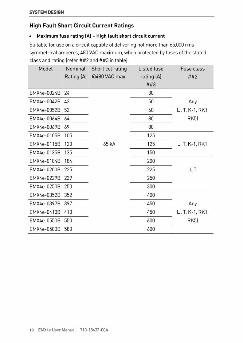
High Fault Short Circuit Current Ratings
• Maximum fuse rating (A) – High fault short circuit current
Suitable for use on a circuit capable of delivering not more than 65,000 rms symmetrical amperes, 480 VAC maximum, when protected by fuses of the stated class and rating (refer ##2 and ##3 in table).
Model Nominal Rating (A)
Short cct rating @480 VAC max.
Listed fuse rating (A)
##3
Fuse class ##2
EMX4e-0024B 24 30
EMX4e-0042B 42 50 Any
EMX4e-0052B 52 60 (J, T, K-1, RK1,
EMX4e-0064B 64 80 RK5)
EMX4e-0069B 69 80
EMX4e-0105B 105 125
EMX4e-0115B 120 65 kA 125 J, T, K-1, RK1
EMX4e-0135B 135 150
EMX4e-0184B 184 200
EMX4e-0200B 225 225 J, T
EMX4e-0229B 229 250
EMX4e-0250B 250 300
EMX4e-0352B 352 400
EMX4e-0397B 397 450 Any
EMX4e-0410B 410 450 (J, T, K-1, RK1,
EMX4e-0550B 550 600 RK5)
EMX4e-0580B 580 600
18 EMX4e User Manual 710-18433-00A
SYSTEM DESIGN
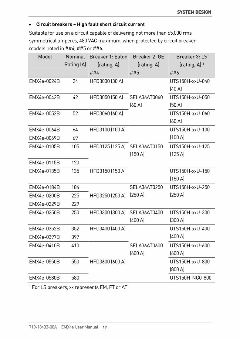
• Circuit breakers – High fault short circuit current
Suitable for use on a circuit capable of delivering not more than 65,000 rms symmetrical amperes, 480 VAC maximum, when protected by circuit breaker models noted in ##4, ##5 or ##6.
Model Nominal Rating (A)
Breaker 1: Eaton (rating, A)
Breaker 2: GE (rating, A)
Breaker 3: LS (rating, A) 1
##4 ##5 ##6
EMX4e-0024B 24 HFD3030 (30 A) UTS150H-xxU-040 (40 A)
EMX4e-0042B 42 HFD3050 (50 A) SELA36AT0060 (60 A)
UTS150H-xxU-050 (50 A)
EMX4e-0052B 52 HFD3060 (60 A) UTS150H-xxU-060 (60 A)
EMX4e-0064B 64 HFD3100 (100 A) UTS150H-xxU-100 (100 A) EMX4e-0069B 69
EMX4e-0105B 105 HFD3125 (125 A) SELA36AT0150 (150 A)
UTS150H-xxU-125 (125 A)
EMX4e-0115B 120
EMX4e-0135B 135 HFD3150 (150 A) UTS150H-xxU-150 (150 A)
EMX4e-0184B 184 SELA36AT0250 (250 A)
UTS150H-xxU-250 (250 A) EMX4e-0200B 225 HFD3250 (250 A)
EMX4e-0229B 229
EMX4e-0250B 250 HFD3300 (300 A) SELA36AT0400 (400 A)
UTS150H-xxU-300 (300 A)
EMX4e-0352B 352 HFD3400 (400 A) UTS150H-xxU-400 (400 A) EMX4e-0397B 397
EMX4e-0410B 410 SELA36AT0600 (600 A)
UTS150H-xxU-600 (600 A)
EMX4e-0550B 550 HFD3600 (600 A) UTS150H-xxU-800 (800 A)
EMX4e-0580B 580 UTS150H-NG0-800 1 For LS breakers, xx represents FM, FT or AT.
710-18433-00A EMX4e User Manual 19

SYSTEM DESIGN
3.14 Fuse Selection for Type 2 Coordination Type 2 coordination is achieved by using semiconductor fuses. These fuses must be able to carry motor start current and have a total clearing I2t less than the I2t of the soft starter SCRs.
When selecting semiconductor fuses for EMX4e, use the I2t values in the table.
For further information on selecting semiconductor fuses, contact your local distributor or download the fuse selection application note from www.aucom.com.
I2t values for Type 2 coordination
Model SCR I2t (A2s)
EMX4e-0024B 1150
EMX4e-0042B 7200
EMX4e-0052B
EMX4e-0064B 15000
EMX4e-0069B
EMX4e-0105B 80000
EMX4e-0115B
EMX4e-0135B 125000
EMX4e-0184B
EMX4e-0200B 320000
EMX4e-0229B
EMX4e-0250B
EMX4e-0352B 202000
EMX4e-0397B
EMX4e-0410B 320000
EMX4e-0550B 781000
EMX4e-0580B
20 EMX4e User Manual 710-18433-00A

SYSTEM DESIGN
3.15 Specifications
Supply Mains voltage (L1, L2, L3) EMX4e-xxxx-V5 ........................................................... 200 ~ 525 VAC (± 10%) EMX4e-xxxx-V7 ........................................................... 380 ~ 600 VAC (± 10%)
Control voltage (A1, A2, A3) EMX4e-xxxxB-xx-C1 (A1, A2) ............... 110~120 VAC (+10%/-15%), 600 mA EMX4e-xxxxB-xx-C1 (A2, A3) ............... 220~240 VAC (+10%/-15%), 600 mA
EMX4e-xxxxB-xx-C2 (A1, A2) ................................. 24 VAC/VDC (± 20%), 2.8 A
Mains frequency ................................................................. 50 Hz ~ 60 Hz (±5 Hz) Rated insulation voltage to earth ........................................................... 600 VAC Rated impulse withstand voltage .................................................................. 6 kV Form designation ......................................................... Bypassed or continuous, .............................................................. semiconductor motor starter form 1
Short circuit capability Coordination with semiconductor fuses .................................................... Type 2 Coordination with HRC fuses ...................................................................... Type 1
Electromagnetic capability (compliant with EU Directive 2014/35/EU) EMC Immunity ................................................................................. IEC 60947-4-2 EMC Emissions ................................................................ IEC 60947-4-2 Class B
Inputs Input rating .............................................................. Active 24 VDC, 8 mA approx Motor thermistor (B4, B5) ....................................... Trip >3.6 kΩ, reset <1.6 kΩ
Outputs Relay outputs ................... 10A @ 250 VAC resistive, 5A @ 250 VAC AC15 pf 0.3 Main contactor (33, 34) .......................................................... Normally Open Relay output A (41, 42, 44) .......................................................... Changeover Relay output B (53, 54) ........................................................... Normally Open Analog output (21, 22) Maximum load ......................................................... 600 Ω (12 VDC @ 20 mA) Accuracy .................................................................................................... ± 5%
Environmental Operating temperature .................. -10 ˚C to 60 ˚C, above 40 ˚C with derating Storage temperature ................................................................. -25 °C to + 60 °C Operating Altitude ............................... 0 - 1000 m, above 1000 m with derating
710-18433-00A EMX4e User Manual 21
SYSTEM DESIGN
Humidity ................................................................. 5% to 95% Relative Humidity Pollution degree .................................................................... Pollution Degree 3 Vibration .......................................................................................... IEC 60068-2-6
Protection EMX4e-0024B ~ EMX4e-0135B ................................................................ IP20 EMX4e-0184B ~ EMX4e-0580B ................................................................ IP00
Heat dissipation During Start ........................................................................ 4.5 watts per ampere During Run EMX4e-0024B ~ EMX4e-0052B ......................................... ≤ 35 watts approx EMX4e-0064B ~ EMX4e-0135B ......................................... ≤ 50 watts approx EMX4e-0184B ~ EMX4e-0250B ....................................... ≤ 120 watts approx EMX4e-0352B ~ EMX4e-0580B ....................................... ≤ 140 watts approx
Motor overload protection Default: The default settings of parameters 1C, 1D and 1E provide Motor Overload Protection: Class 10, Trip Current 105% of FLA (full load amperage) or equivalent.
Certification CE .................................................................................................... EN 60947-4-2
C-UL ...................................................................................... C22.2 Nº 60947-4-2
UL .................................................................................................... UL 60947-4-2
RCM ............................................................................................... IEC 60947-4-2
3.16 Disposal Instructions
Equipment containing electrical components may not be disposed of together with domestic waste.
It must be collected separately as electrical and electronic waste according to local and currently valid legislation.
22 EMX4e User Manual 710-18433-00A
INSTALLATION
4. Installation
WARNING Do not apply mains voltage to the starter until all wiring is complete.
WARNING Always apply control voltage before (or with) mains voltage.
4.1 Command Source The EMX4e can be started and stopped via the digital inputs, remote keypad, communication network or smart card. The command source can be set via the Setup Tools, or using parameter 1A Command Source.
4.2 Setup Procedure Overview 1. Mount the soft starter (refer to Physical Installation on page 13 for details).
2. Connect control wiring (refer to Input Terminals on page 24 for details).
3. Apply control voltage to the starter.
4. Configure your application:
1. Press MENU to open the Menu.
2. Press to open the Quick Setup menu.
3. Scroll through the list to find your application, then press to begin the configuration process (refer to Quick Setup on page 31 for details).
5. If your application is not listed in Quick Setup:
1. Press to return to the Menu.
2. Use to scroll to Main Menu and press .
3. Scroll to Motor Details and press , then press again to edit parameter 1B Motor Full Load Current.
4. Set parameter 1B to match the motor's full load current (FLC).
5. Press to save the setting.
6. Close the Menu by pressing repeatedly.
7. (Optional) Use the built-in simulation tools to check that the control wiring is connected correctly (refer to Run simulation on page 33).
8. Power off the soft starter.
9. Connect the motor cables to starter output terminals 2/T1, 4/T2, 6/T3.
10. Connect mains supply cables to starter input terminals 1/L1, 3/L2, 5/L3 (refer to Power Terminations on page 28).
The soft starter is now ready to control the motor.
710-18433-00A EMX4e User Manual 23
INSTALLATION
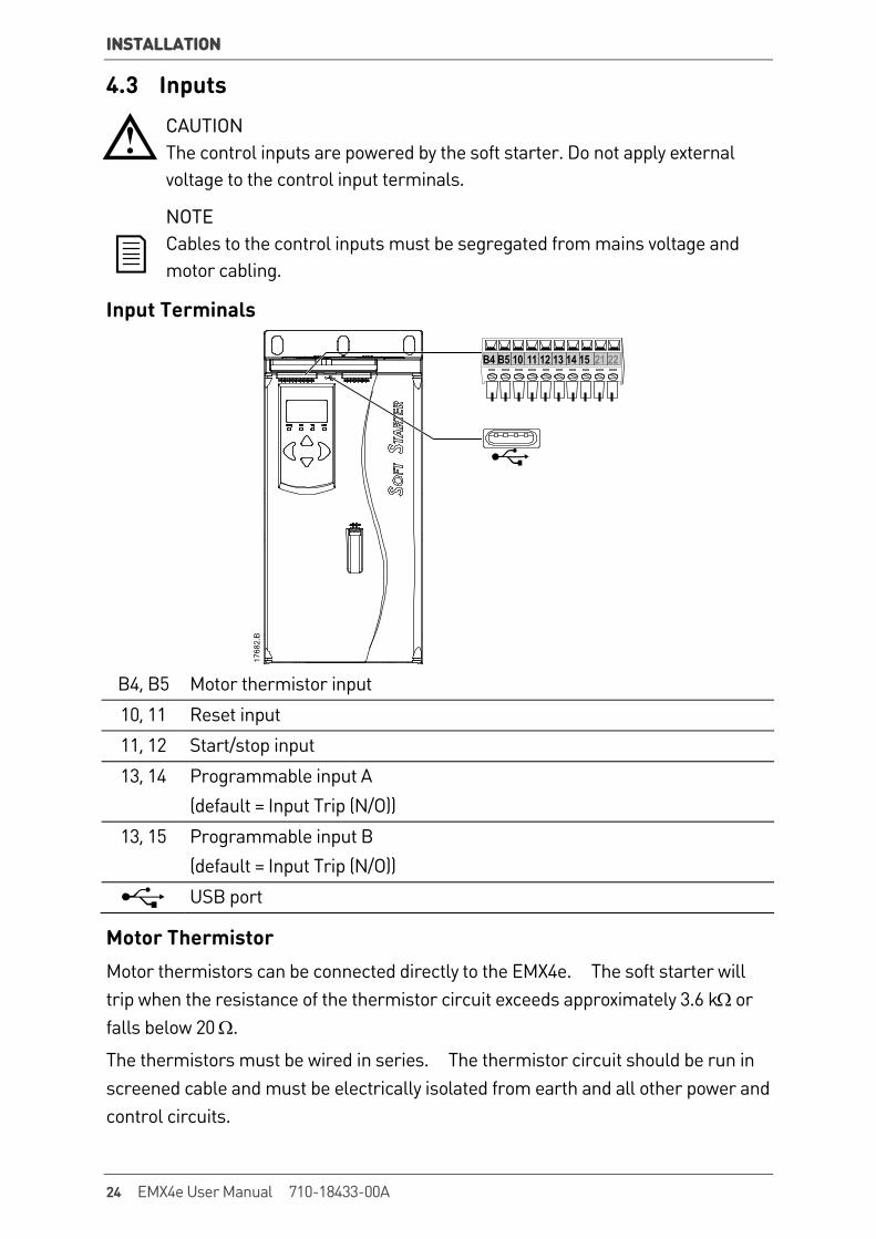
4.3 Inputs
CAUTION The control inputs are powered by the soft starter. Do not apply external voltage to the control input terminals.
NOTE Cables to the control inputs must be segregated from mains voltage and motor cabling.
Input Terminals
B4 B5 10 11 12 13 14 15 21 22
B4, B5 Motor thermistor input
10, 11 Reset input
11, 12 Start/stop input
13, 14 Programmable input A (default = Input Trip (N/O))
13, 15 Programmable input B (default = Input Trip (N/O))
USB port
Motor Thermistor Motor thermistors can be connected directly to the EMX4e. The soft starter will trip when the resistance of the thermistor circuit exceeds approximately 3.6 kΩ or falls below 20 Ω.
The thermistors must be wired in series. The thermistor circuit should be run in screened cable and must be electrically isolated from earth and all other power and control circuits.
24 EMX4e User Manual 710-18433-00A

INSTALLATION
NOTE The thermistor input is disabled by default, but activates automatically when a thermistor is detected. If thermistors have previously been connected to the EMX4e but are no longer required, use the Thermistor Reset function to disable the thermistor. Thermistor Reset is accessed via the Setup Tools.
Start/Stop The EMX4e requires two-wire control.
A
B17
622.
A
A Reset
B Start/Stop
NOTE The EMX4e will only accept commands from the control inputs if parameter 1A Command Source is set to Digital Input.
Reset/Starter Disable The reset input (10, 11) is normally closed by default. The EMX4e will not perform a start if the reset input is open. The display will show "Not Ready".
If the reset input opens while the EMX4e is running, the starter will remove power and allow the motor to coast to stop.
NOTE The reset input can be configured for normally closed operation. Use parameter 7I Reset/Enable Logic.
Programmable Inputs The programmable inputs (13, 14 and 13, 15) allow external equipment to control the starter.
The operation of the programmable inputs is controlled by parameters 7A ~ 7H.
USB Port The USB port can be used to upload a configuration file, or download parameter settings and event log information from the starter. Refer to USB Save & Load on page 34 for details.
710-18433-00A EMX4e User Manual 25

INSTALLATION
4.4 Outputs
Output Terminals
33 34 41 42 44 53 54
B4 B5 10 11 12 13 14 15 21 22
21, 22 Analog output
33, 34 Main contactor output
41, 42, 44 Relay output A (default = Run)
53, 54 Relay output B (default = Run)
Analog Output The EMX4e has an analog output, which can be connected to associated equipment to monitor motor performance.
The operation of the analog output is controlled by parameters 9A ~ 9D.
Main Contactor Output The main contactor output (33, 34) closes as soon as the soft starter receives a start command and remains closed while the soft starter is controlling the motor (until the motor starts a coast to stop, or until the end of a soft stop). The main contactor output will also open if the soft starter trips.
CAUTION Some electronic contactor coils are not suitable for direct switching with PCB mount relays. Consult the contactor manufacturer/supplier to confirm suitability.
Programmable Outputs The programmable outputs (41, 42, 44 and 53, 54) can report the status of the starter, or can be used to control associated equipment.
The operation of the programmable outputs is controlled by parameters 8A ~ 8F.
26 EMX4e User Manual 710-18433-00A

INSTALLATION
4.5 Control Voltage
Control Voltage Terminals
A3 A1 A2
Connect the control supply according to the supply voltage being used. • EMX4e-xxxxB-xx-C1 (110~120 VAC): A1, A2 • EMX4e-xxxxB-xx-C1 (220~240 VAC): A2, A3 • EMX4e-xxxxB-xx-C2 (24 VAC/VDC): A1, A2
UL Compliant Installation For models EMX4e-0184B to EMX4e-0580B to be UL compliant, supplementary or branch overcurrent protection must be used on the control circuit supply (A1, A2, A3), in accordance with the electrical code applicable at the installation location.
Models Recommended lugs part No.
EMX4e-0184B
EMX4e-0200B OPHD 185-10
EMX4e-0229B
EMX4e-0250B
EMX4e-0352B
EMX4e-0397B OPHD 150-12
EMX4e-0410B
EMX4e-0550B OPHD 240-12
EMX4e-0580B
710-18433-00A EMX4e User Manual 27

INSTALLATION
4.6 Power Terminations The power input and output terminals for EMX4e are at the bottom of the unit.
• Models EMX4e-0024B~EMX4e-0135B use cage clamps. • Models EMX4e-0184B~EMX4e-0580B use busbars.
NOTE Some units use aluminium busbars. When connecting power terminations, we recommend cleaning the surface contact area thoroughly (using an emery or stainless steel brush) and using an appropriate jointing compound to prevent corrosion.
Use only copper stranded or solid conductors, rated for 75 ºC or higher.
EMX4e-0024B~EMX4e-0135B
0596
6.E
11290.A
Cable size: 6-70 mm2 (AWG 10-2/0) Torque: 4 Nm (2.9 ft-lb) 14 mm (0.55 inch)
Torx T20 x 150
Flat 7 mm x 150
EMX4e-0184B~EMX4e-0250B EMX4e-0352B~EMX4e-0580B
19 Nm (14.0 ft-lb) 66 Nm (49.0 ft-lb)
6 mm20 mm
9 mm(M8)
1704
5.A
6 mm34 mm
13 mm(M12)
1704
7.A
NOTE If the installation requires large diameter cables, it is possible to complete each termination with two smaller cables, one on each side of the busbar.
28 EMX4e User Manual 710-18433-00A
INSTALLATION
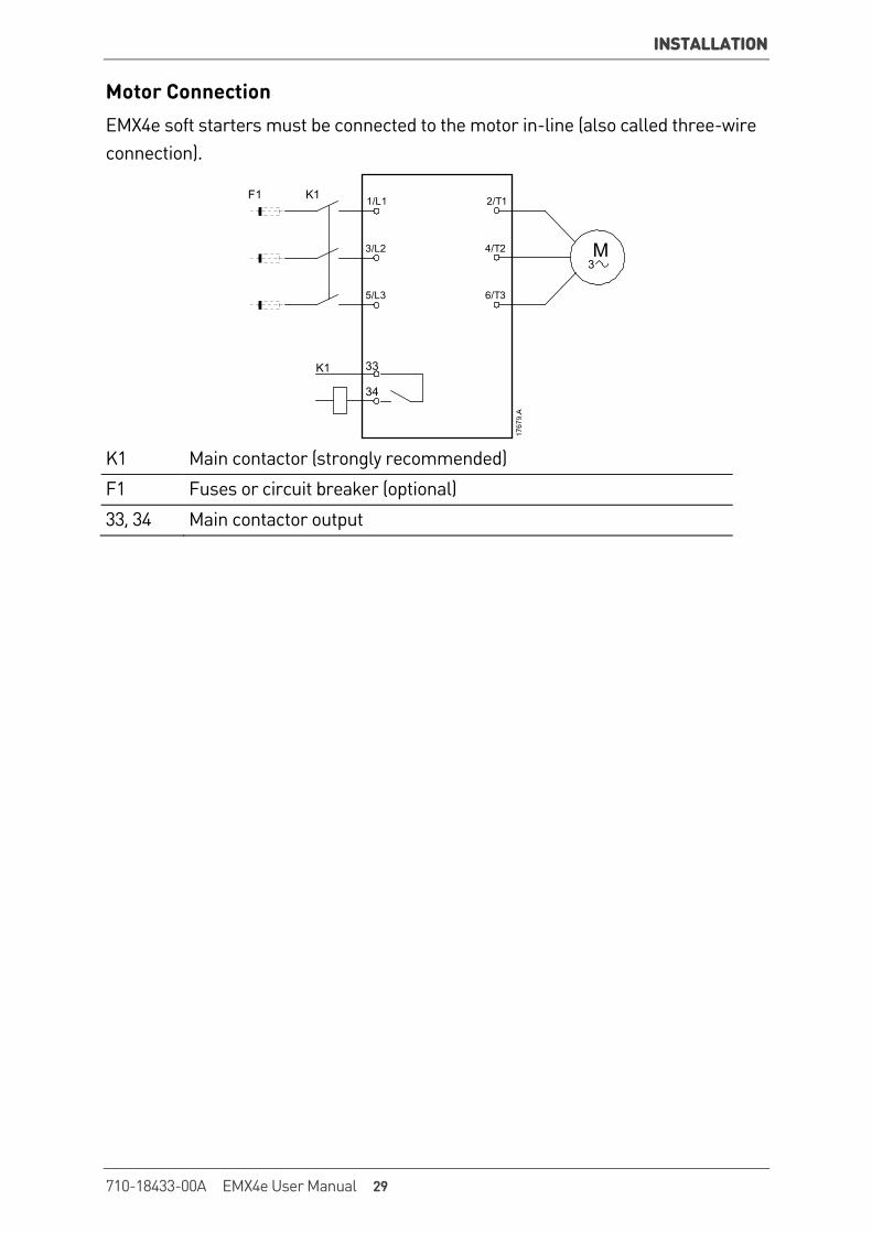
Motor Connection EMX4e soft starters must be connected to the motor in-line (also called three-wire connection).
34
33K1
K1F1
6/T3
2/T1
5/L3
3/L2
1/L1
4/T2 M3
K1 Main contactor (strongly recommended)
F1 Fuses or circuit breaker (optional)
33, 34 Main contactor output
710-18433-00A EMX4e User Manual 29

INSTALLATION
4.7 Typical Installation The EMX4e is installed with a main contactor (AC3 rated). Control voltage must be supplied from the input side of the contactor.
The main contactor is controlled by the main contactor output (33, 34).
A +
M
42
41
6/T3
2/T1
33
34
4/T2
54
53
44
21
22B5
B4
12
13
14
15
11
A2
A1
A3
5/L3
3/L2
10
1/L1F1
S1
S2 K1
K1
7
6
5
3
21
4
9
8
17674.A
(L/+)
1 Three-phase supply K1 Main contactor
2 Motor F1 Semiconductor fuses (optional)
3 Control voltage (soft starter) 10, 11 (S1) Reset
4 Digital inputs 11, 12 (S2) Start/Stop
5 Motor thermistor input 13, 14 Programmable input A (default = Input Trip (N/O))
6 Relay outputs 13, 15 Programmable input B (default = Input Trip (N/O))
7 Analog output B4, B5 Motor thermistor input
8 Control voltage (external equipment)
33, 34 Main contactor output
9 Pilot lamps 41, 42, 44 Relay output A (default = Run) 53, 54 Relay output B (default = Trip) 21, 22 Analog output
30 EMX4e User Manual 710-18433-00A
INSTALLATION
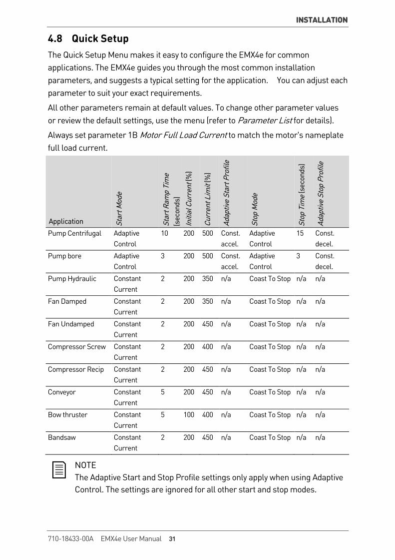
4.8 Quick Setup The Quick Setup Menu makes it easy to configure the EMX4e for common applications. The EMX4e guides you through the most common installation parameters, and suggests a typical setting for the application. You can adjust each parameter to suit your exact requirements.
All other parameters remain at default values. To change other parameter values or review the default settings, use the menu (refer to Parameter List for details).
Always set parameter 1B Motor Full Load Current to match the motor's nameplate full load current.
Application Star
t Mod
e
Star
t Ram
p Ti
me
(sec
onds
)
Initi
al C
urre
nt (%
)
Curr
ent L
imit
(%)
Adap
tive
Star
t Pro
file
Stop
Mod
e
Stop
Tim
e (s
econ
ds)
Adap
tive
Stop
Pro
file
Pump Centrifugal Adaptive Control
10 200 500 Const. accel.
Adaptive Control
15 Const. decel.
Pump bore Adaptive Control
3 200 500 Const. accel.
Adaptive Control
3 Const. decel.
Pump Hydraulic Constant Current
2 200 350 n/a Coast To Stop n/a n/a
Fan Damped Constant Current
2 200 350 n/a Coast To Stop n/a n/a
Fan Undamped Constant Current
2 200 450 n/a Coast To Stop n/a n/a
Compressor Screw Constant Current
2 200 400 n/a Coast To Stop n/a n/a
Compressor Recip Constant Current
2 200 450 n/a Coast To Stop n/a n/a
Conveyor Constant Current
5 200 450 n/a Coast To Stop n/a n/a
Bow thruster Constant Current
5 100 400 n/a Coast To Stop n/a n/a
Bandsaw Constant Current
2 200 450 n/a Coast To Stop n/a n/a
NOTE The Adaptive Start and Stop Profile settings only apply when using Adaptive Control. The settings are ignored for all other start and stop modes.
710-18433-00A EMX4e User Manual 31
SETUP TOOLS
5. Setup Tools Setup Tools includes options to load or save parameters to a backup file, set the starter's network address, check the status of the inputs and outputs, reset the thermal models or test operation using the Run Simulation.
To access the Setup Tools, press MENU to open the Menu then select Setup Tools.
5.1 Command Source The EMX4e can be started and stopped via the digital inputs, remote keypad, communication network or smart card. The command source can be set via the Setup Tools, or using parameter 1A Command Source.
If the remote keypad is installed, the LCL/RMT button provides shortcut access to the Command Source function in Setup Tools.
5.2 Commissioning Commissioning lets the starter be started and stopped via the local keypad. Use the
and buttons to select a function, then press to send the selected command to the starter. The available functions are:
• Quick stop (coast to stop)/Reset • Start • Stop
32 EMX4e User Manual 710-18433-00A
SETUP TOOLS
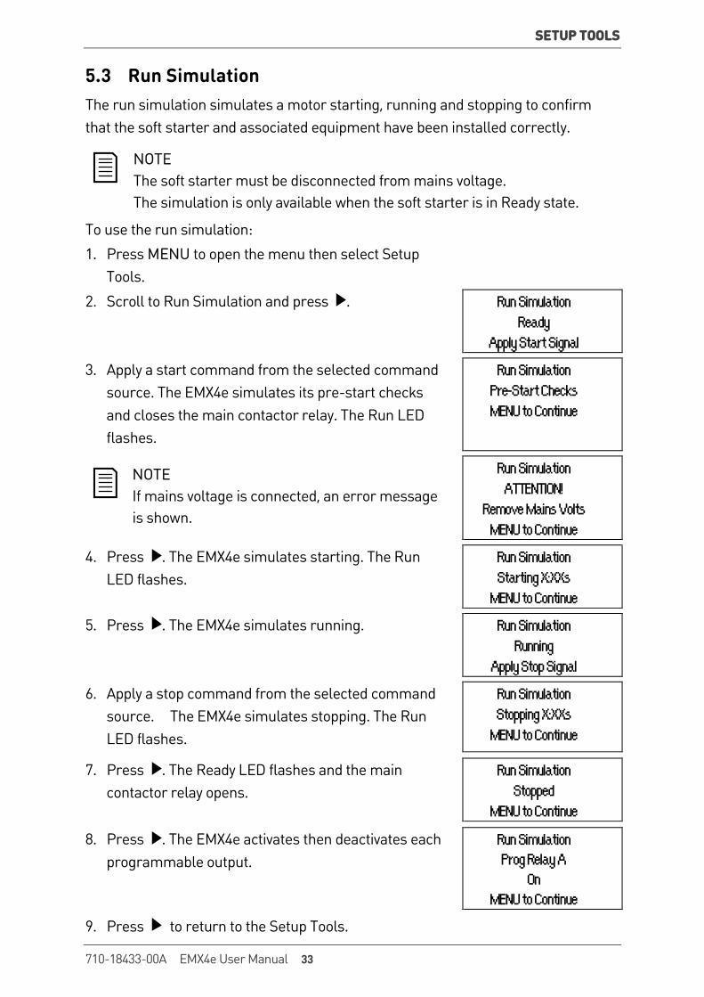
5.3 Run Simulation The run simulation simulates a motor starting, running and stopping to confirm that the soft starter and associated equipment have been installed correctly.
NOTE The soft starter must be disconnected from mains voltage. The simulation is only available when the soft starter is in Ready state.
To use the run simulation:
1. Press MENU to open the menu then select Setup Tools.
2. Scroll to Run Simulation and press . Run Simulation Ready Apply Start Signal
3. Apply a start command from the selected command source. The EMX4e simulates its pre-start checks and closes the main contactor relay. The Run LED flashes.
Run Simulation Pre-Start Checks MENU to Continue
NOTE If mains voltage is connected, an error message is shown.
Run Simulation ATTENTION! Remove Mains Volts MENU to Continue
4. Press . The EMX4e simulates starting. The Run LED flashes.
Run Simulation Starting X:XXs MENU to Continue
5. Press . The EMX4e simulates running. Run Simulation Running Apply Stop Signal
6. Apply a stop command from the selected command source. The EMX4e simulates stopping. The Run LED flashes.
Run Simulation Stopping X:XXs MENU to Continue
7. Press . The Ready LED flashes and the main contactor relay opens.
Run Simulation Stopped MENU to Continue
8. Press . The EMX4e activates then deactivates each programmable output.
Run Simulation Prog Relay A On MENU to Continue
9. Press to return to the Setup Tools.
710-18433-00A EMX4e User Manual 33
SETUP TOOLS
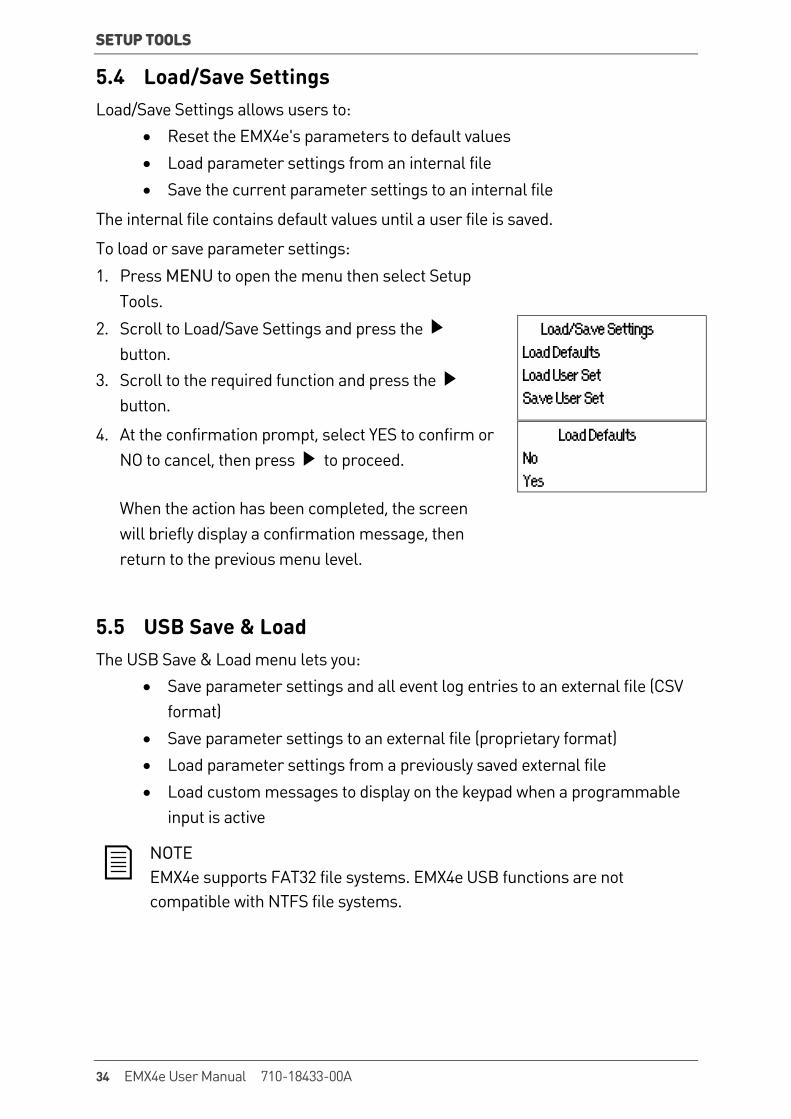
5.4 Load/Save Settings Load/Save Settings allows users to:
• Reset the EMX4e's parameters to default values • Load parameter settings from an internal file • Save the current parameter settings to an internal file
The internal file contains default values until a user file is saved.
To load or save parameter settings:
1. Press MENU to open the menu then select Setup Tools.
2. Scroll to Load/Save Settings and press the button.
3. Scroll to the required function and press the button.
Load/Save Settings Load Defaults Load User Set Save User Set
4. At the confirmation prompt, select YES to confirm or NO to cancel, then press to proceed.
Load Defaults No Yes
When the action has been completed, the screen will briefly display a confirmation message, then return to the previous menu level.
5.5 USB Save & Load The USB Save & Load menu lets you:
• Save parameter settings and all event log entries to an external file (CSV format)
• Save parameter settings to an external file (proprietary format) • Load parameter settings from a previously saved external file • Load custom messages to display on the keypad when a programmable
input is active
NOTE EMX4e supports FAT32 file systems. EMX4e USB functions are not compatible with NTFS file systems.
34 EMX4e User Manual 710-18433-00A
SETUP TOOLS
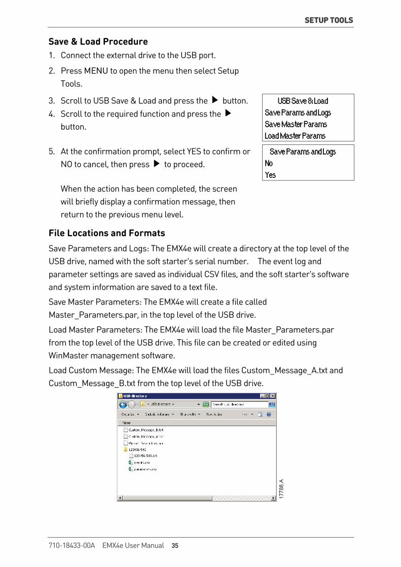
Save & Load Procedure 1. Connect the external drive to the USB port.
2. Press MENU to open the menu then select Setup Tools.
3. Scroll to USB Save & Load and press the button. 4. Scroll to the required function and press the
button.
USB Save & Load Save Params and Logs Save Master Params Load Master Params
5. At the confirmation prompt, select YES to confirm or NO to cancel, then press to proceed.
Save Params and Logs No Yes
When the action has been completed, the screen will briefly display a confirmation message, then return to the previous menu level.
File Locations and Formats Save Parameters and Logs: The EMX4e will create a directory at the top level of the USB drive, named with the soft starter's serial number. The event log and parameter settings are saved as individual CSV files, and the soft starter's software and system information are saved to a text file.
Save Master Parameters: The EMX4e will create a file called Master_Parameters.par, in the top level of the USB drive.
Load Master Parameters: The EMX4e will load the file Master_Parameters.par from the top level of the USB drive. This file can be created or edited using WinMaster management software.
Load Custom Message: The EMX4e will load the files Custom_Message_A.txt and Custom_Message_B.txt from the top level of the USB drive.
710-18433-00A EMX4e User Manual 35
SETUP TOOLS
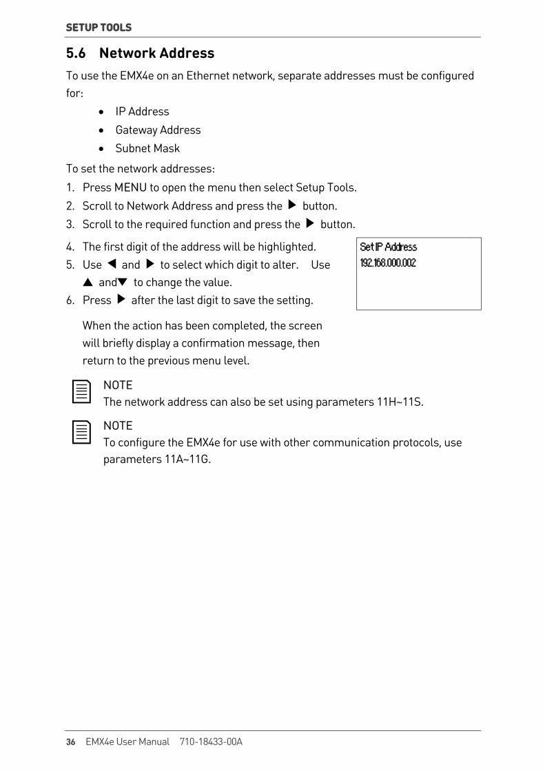
5.6 Network Address To use the EMX4e on an Ethernet network, separate addresses must be configured for:
• IP Address • Gateway Address • Subnet Mask
To set the network addresses:
1. Press MENU to open the menu then select Setup Tools. 2. Scroll to Network Address and press the button. 3. Scroll to the required function and press the button.
4. The first digit of the address will be highlighted. 5. Use and to select which digit to alter. Use
and to change the value. 6. Press after the last digit to save the setting.
Set IP Address 192.168.000.002
When the action has been completed, the screen will briefly display a confirmation message, then return to the previous menu level.
NOTE The network address can also be set using parameters 11H~11S.
NOTE To configure the EMX4e for use with other communication protocols, use parameters 11A~11G.
36 EMX4e User Manual 710-18433-00A
SETUP TOOLS
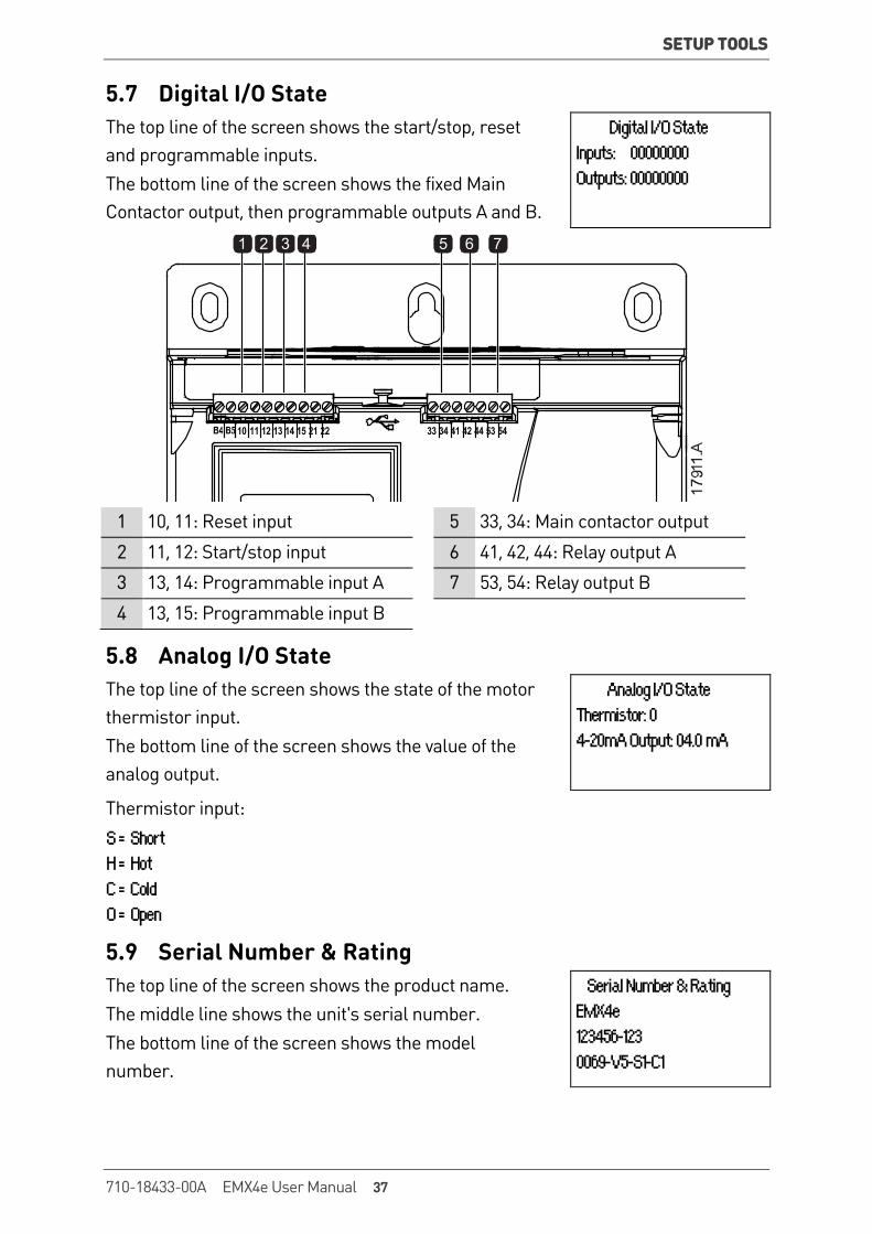
5.7 Digital I/O State The top line of the screen shows the start/stop, reset and programmable inputs. The bottom line of the screen shows the fixed Main Contactor output, then programmable outputs A and B.
Digital I/O State Inputs: 00000000 Outputs: 00000000
33 34 41 42 44 53 5410 11 12 13 14 15 21 22
7654321
1 10, 11: Reset input 5 33, 34: Main contactor output
2 11, 12: Start/stop input 6 41, 42, 44: Relay output A
3 13, 14: Programmable input A 7 53, 54: Relay output B
4 13, 15: Programmable input B
5.8 Analog I/O State The top line of the screen shows the state of the motor thermistor input. The bottom line of the screen shows the value of the analog output.
Analog I/O State Thermistor: 0 4-20mA Output: 04.0 mA
Thermistor input: S = Short H = Hot C = Cold O = Open
5.9 Serial Number & Rating The top line of the screen shows the product name. The middle line shows the unit's serial number. The bottom line of the screen shows the model number.
Serial Number & Rating EMX4e 123456-123 0069-V5-S1-C1
710-18433-00A EMX4e User Manual 37

SETUP TOOLS
5.10 Software Versions The software versions screen reports the version of each software component in the starter:
• user interface • motor control • remote keypad (if connected) • parameter list • bootloader • expansion card (if fitted)
NOTE Updated software, including alternative languages, can be loaded into the starter via the USB port if required. Contact your local supplier for further information.
5.11 Thermistor Reset The thermistor input is disabled by default, but activates automatically when a thermistor is detected. If thermistors have previously been connected to the EMX4e but are no longer required, use the Thermistor Reset function to disable the thermistor.
5.12 Reset Thermal Model The EMX4e's advanced thermal modelling software constantly monitors the motor's performance. This allows the EMX4e to calculate the motor's temperature and ability to start successfully at any time.
The thermal model can be reset if required.
CAUTION Resetting the motor thermal model will compromise thermal model protection and may compromise motor life. Only reset the thermal model in an emergency.
38 EMX4e User Manual 710-18433-00A
LOGS
6. Logs The Logs Menu provides information on events, trips and starter performance.
To access the Logs Menu on the local keypad, press MENU to open the Menu then select Logs. On the remote keypad, press LOGS.
6.1 Event Log The Event Log stores details of the starter's most recent trips, warnings, and operations (including starts, stops and configuration changes).
Event 1 is the most recent and event 384 is the oldest stored event.
NOTE Events in the EMX4e event log are timestamped based on time elapsed since control power was last applied. The timestamp resets to zero when control power is cycled.
NOTE The event log can be exported to an external file for analysis away from the starter. Refer to USB Save & Load on page 34 for details.
6.2 Counters The counters store statistics on the starter's operation:
• Hours run (lifetime and since counter last reset) • Number of starts (lifetime and since counter last reset) • Number of times the thermal model has been reset
To view the counters: 1. Open the Logs Menu.
2. Scroll to counters and press .
3. Use the and buttons to scroll through the counters. Press to view details.
4. To reset a counter, press then use the and buttons to select Reset/Do Not Reset. Press STORE to confirm the action.
To close the counter and return to the Logs Menu, press .
710-18433-00A EMX4e User Manual 39
KEYPAD AND FEEDBACK
7. Keypad and Feedback 7.1 The Keypad
Local keypad Remote keypad (if installed)
Ready Run Trip Local
MenuStore
ExitReset
1
2
3
1769
1.A
Start Stop Reset LCLRMT
MenuStoreExit
AltLogs Tools17
692.
A
1
2
3
4
5
6
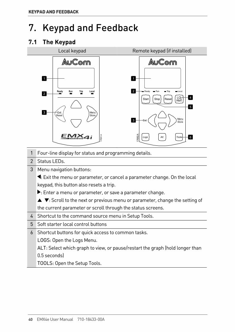
1 Four-line display for status and programming details.
2 Status LEDs.
3 Menu navigation buttons: : Exit the menu or parameter, or cancel a parameter change. On the local
keypad, this button also resets a trip. : Enter a menu or parameter, or save a parameter change. : Scroll to the next or previous menu or parameter, change the setting of
the current parameter or scroll through the status screens.
4 Shortcut to the command source menu in Setup Tools.
5 Soft starter local control buttons
6 Shortcut buttons for quick access to common tasks. LOGS: Open the Logs Menu. ALT: Select which graph to view, or pause/restart the graph (hold longer than 0.5 seconds) TOOLS: Open the Setup Tools.
40 EMX4e User Manual 710-18433-00A
KEYPAD AND FEEDBACK
7.2 Remote Keypad The remote keypad can be used to control the soft starter if parameter 1A Command Source is set to 'Remote Keypad'.
• If the remote keypad is not selected as the command source, the START, STOP and RESET buttons will have no effect.
• The menu navigation buttons and display on the remote keypad are always active.
• If a button is pressed on the starter's local keypad, the display on the remote keypad will update to match.
NOTE The remote keypad can be safely connected or removed while the starter is running. It is not necessary to remove mains or control voltage.
NOTE If parameter 1A Command Source is set to Remote Keypad, removing the remote keypad will cause a trip.
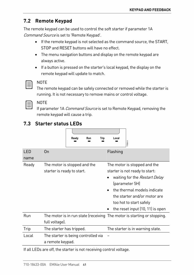
7.3 Starter status LEDs
Ready Run Trip Local
1769
4.A
LED name
On Flashing
Ready The motor is stopped and the starter is ready to start.
The motor is stopped and the starter is not ready to start: • waiting for the Restart Delay
(parameter 5H) • the thermal models indicate
the starter and/or motor are too hot to start safely
• the reset input (10, 11) is open
Run The motor is in run state (receiving full voltage).
The motor is starting or stopping.
Trip The starter has tripped. The starter is in warning state.
Local The starter is being controlled via a remote keypad.
–
If all LEDs are off, the starter is not receiving control voltage.
710-18433-00A EMX4e User Manual 41

KEYPAD AND FEEDBACK
7.4 Displays The keypad displays a wide range of performance information about the soft starter. To scroll through the feedback screens, press the and buttons.
Starter information At power-up, the starter information screen shows details of the starter's rating, software versions and serial number.
Welcome
01.01/01.00/01.00 Software versions: user interface, motor control, remote keypad
EMX4e-0069B-V5-S1-C1 Model code: current rating, mains voltage, frame size, control voltage
(remote keypad software version is only displayed when a remote keypad is connected)
Starter Status The starter status screen shows details of the starter's operating status, and real-time performance information as selected in parameters 10H User Parameter 1 and 10I User Parameter 2.
Ready M1 X%
Current The current screen shows real-time line current on each phase.
Phase Currents 000.0A 000.0A 000.0A
Last Start Information The last start information screen shows details of the most recent successful start:
• start duration (seconds) • maximum start current drawn (as a percentage of motor full load
current) • calculated rise in motor temperature
Last start 010 s 350 % FLC ∆ Temp 5%
42 EMX4e User Manual 710-18433-00A
KEYPAD AND FEEDBACK
Performance Graph The performance graph provides a real-time display of operating performance. Use parameters 10B~10E to format the graph.
The display on the main keypad shows information for motor current.
0505
0.C
000.0 A 0-400%
If a remote keypad is connected, press ALT to change the graph data. The graph can show:
• motor current • motor temperature • motor pf • analog input data from the smart card (if installed)
710-18433-00A EMX4e User Manual 43
OPERATION
8. Operation 8.1 Start, Stop and Reset Commands The EMX4e can be started and stopped via the digital inputs, remote keypad, communication network or smart card. The command source can be set via the Setup Tools, or using parameter 1A Command Source.
• The EMX4e will only accept Start and Reset commands from the designated command source.
• The EMX4e will accept Stop commands from the designated command source, but can be forced to stop by opening the reset input.
• The programmable input can be used to override the selected command source (refer to parameter 7A Input A Function).
8.2 Command Override The programmable input (13, 14) can be used to override the command source, for situations where the normal control mechanism has been lost. Set parameter 7A Input A Function to the alternative command source (eg 'Command Override: Keypad').
While the input is active, the starter will only accept commands from the selected override source. To restore control to the command source selected in parameter 1A Command Source, reopen the input.
8.3 Emergency Mode Emergency mode allows the EMX4e to run the motor and ignore trip conditions.
Emergency mode is controlled via a programmable input (input A 13, 14 or input B 13, 15) and parameter 7A Input A Function/7E Input B Function must be set to 'Emergency Mode'. A closed circuit across 13, 14 activates emergency mode. When the EMX4e receives a start command, it will continue to run until a stop command is received, ignoring all trips and warnings.
Emergency mode can be used in conjunction with any command source.
NOTE Although emergency mode operation satisfies the functionality requirements of Fire Mode, AuCom does not recommend its use in situations that require testing and/or compliance with specific standards as it is not certified.
44 EMX4e User Manual 710-18433-00A

OPERATION
CAUTION Continued use of emergency mode is not recommended. Emergency mode may compromise the starter and/or motor life as all protections and trips are disabled.
Using the starter in emergency mode will void the product warranty.
8.4 Auxiliary Trip An external trip circuit (such as a low pressure alarm switch for a pumping system) can be used to trip the soft starter and stop the motor. The external circuit is connected to a programmable input (input A 13, 14 or input B 13, 15). To control the behaviour of the trip, set the following parameters:
• Parameter 7A Input A Function: select 'Input Trip (N/O)'. • Parameter 7B Input A Trip: set as required. For example, 'Run Only'
limits the input trip to when the soft starter is running only. • Parameter 7C Input A Trip Delay: sets a delay between the input
activating and the soft starter tripping. • Parameter 7D Input A Initial Delay: sets a delay before the soft starter
monitors the state of the input, after the start signal. For example, a delay may be required to allow time for pipeline pressure to build up.
• Parameter 7J Input A Name: select a name, eg 'Input A Trip' (optional).
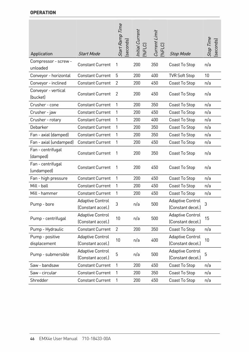
8.5 Typical Control Methods The requirements of an application differ between each installation, but the methods listed below are often a good starting point for common applications.
Application Start Mode Star
t Ram
p Ti
me
(s
econ
ds)
Initi
al C
urre
nt
(%FL
C)
Curr
ent L
imit
(%
FLC)
Stop Mode Stop
Tim
e
(sec
onds
)
Bow thruster Constant Current 5 100 400 Coast To Stop n/a
Centrifuge (Separator) Constant Current 1 200 450 Coast To Stop n/a
Chipper Constant Current 1 200 450 Coast To Stop n/a
Compressor - reciprocating - loaded
Constant Current 1 200 450 Coast To Stop n/a
Compressor - reciprocating - unloaded
Constant Current 1 200 400 Coast To Stop n/a
Compressor - screw - loaded
Constant Current 1 200 400 Coast To Stop n/a
710-18433-00A EMX4e User Manual 45
OPERATION
Application Start Mode Star
t Ram
p Ti
me
(s
econ
ds)
Initi
al C
urre
nt
(%FL
C)
Curr
ent L
imit
(%
FLC)
Stop Mode Stop
Tim
e
(sec
onds
)
Compressor - screw - unloaded
Constant Current 1 200 350 Coast To Stop n/a
Conveyor - horizontal Constant Current 5 200 400 TVR Soft Stop 10
Conveyor - inclined Constant Current 2 200 450 Coast To Stop n/a
Conveyor - vertical (bucket)
Constant Current 2 200 450 Coast To Stop n/a
Crusher - cone Constant Current 1 200 350 Coast To Stop n/a
Crusher - jaw Constant Current 1 200 450 Coast To Stop n/a
Crusher - rotary Constant Current 1 200 400 Coast To Stop n/a
Debarker Constant Current 1 200 350 Coast To Stop n/a
Fan - axial (damped) Constant Current 1 200 350 Coast To Stop n/a
Fan - axial (undamped) Constant Current 1 200 450 Coast To Stop n/a
Fan - centrifugal (damped)
Constant Current 1 200 350 Coast To Stop n/a
Fan - centrifugal (undamped)
Constant Current 1 200 450 Coast To Stop n/a
Fan - high pressure Constant Current 1 200 450 Coast To Stop n/a
Mill - ball Constant Current 1 200 450 Coast To Stop n/a
Mill - hammer Constant Current 1 200 450 Coast To Stop n/a
Pump - bore Adaptive Control (Constant accel.)
3 n/a 500 Adaptive Control (Constant decel.)
3
Pump - centrifugal Adaptive Control (Constant accel.)
10 n/a 500 Adaptive Control (Constant decel.)
15
Pump - Hydraulic Constant Current 2 200 350 Coast To Stop n/a
Pump - positive displacement
Adaptive Control (Constant accel.)
10 n/a 400 Adaptive Control (Constant decel.)
10
Pump - submersible Adaptive Control (Constant accel.)
5 n/a 500 Adaptive Control (Constant decel.)
5
Saw - bandsaw Constant Current 1 200 450 Coast To Stop n/a
Saw - circular Constant Current 1 200 350 Coast To Stop n/a
Shredder Constant Current 1 200 450 Coast To Stop n/a
46 EMX4e User Manual 710-18433-00A
OPERATION
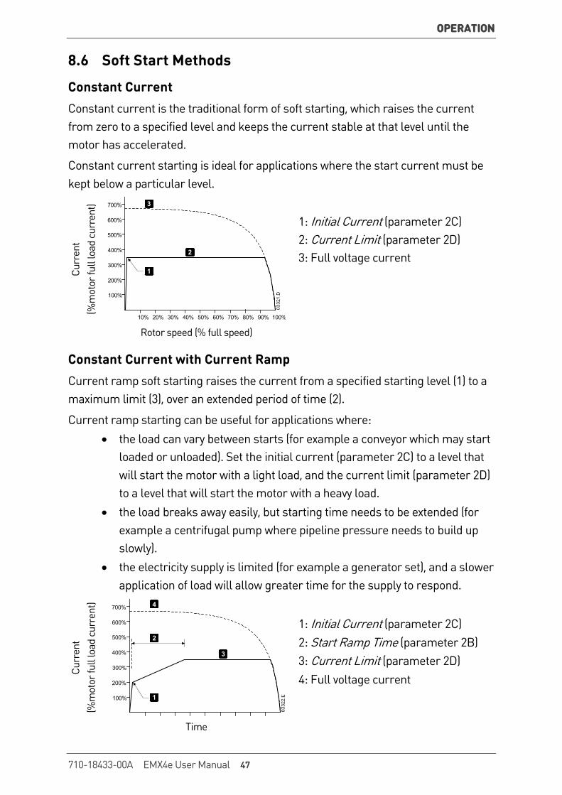
8.6 Soft Start Methods
Constant Current Constant current is the traditional form of soft starting, which raises the current from zero to a specified level and keeps the current stable at that level until the motor has accelerated.
Constant current starting is ideal for applications where the start current must be kept below a particular level.
Curr
ent
(%
mot
or fu
ll lo
ad c
urre
nt) 700%
600%
500%
300%
100%
400%
200%
10% 20% 30% 40% 50% 60% 70% 80% 90% 100%
1
3
2
1: Initial Current (parameter 2C) 2: Current Limit (parameter 2D) 3: Full voltage current
Rotor speed (% full speed)
Constant Current with Current Ramp Current ramp soft starting raises the current from a specified starting level (1) to a maximum limit (3), over an extended period of time (2).
Current ramp starting can be useful for applications where: • the load can vary between starts (for example a conveyor which may start
loaded or unloaded). Set the initial current (parameter 2C) to a level that will start the motor with a light load, and the current limit (parameter 2D) to a level that will start the motor with a heavy load.
• the load breaks away easily, but starting time needs to be extended (for example a centrifugal pump where pipeline pressure needs to build up slowly).
• the electricity supply is limited (for example a generator set), and a slower application of load will allow greater time for the supply to respond.
Curr
ent
(%
mot
or fu
ll lo
ad c
urre
nt)
700%
600%
500%
300%
100%
400%
200%
1
4
3
2
1: Initial Current (parameter 2C) 2: Start Ramp Time (parameter 2B) 3: Current Limit (parameter 2D) 4: Full voltage current
Time
710-18433-00A EMX4e User Manual 47
OPERATION
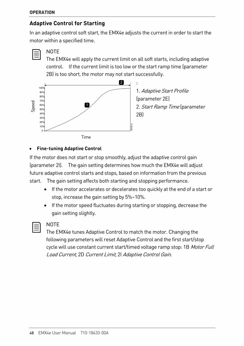
Adaptive Control for Starting In an adaptive control soft start, the EMX4e adjusts the current in order to start the motor within a specified time.
NOTE The EMX4e will apply the current limit on all soft starts, including adaptive control. lf the current limit is too low or the start ramp time (parameter 2B) is too short, the motor may not start successfully.
Spee
d
: 1. Adaptive Start Profile (parameter 2E) 2. Start Ramp Time (parameter 2B)
Time
• Fine-tuning Adaptive Control
If the motor does not start or stop smoothly, adjust the adaptive control gain (parameter 2I). The gain setting determines how much the EMX4e will adjust future adaptive control starts and stops, based on information from the previous start. The gain setting affects both starting and stopping performance.
• If the motor accelerates or decelerates too quickly at the end of a start or stop, increase the gain setting by 5%~10%.
• If the motor speed fluctuates during starting or stopping, decrease the gain setting slightly.
NOTE The EMX4e tunes Adaptive Control to match the motor. Changing the following parameters will reset Adaptive Control and the first start/stop cycle will use constant current start/timed voltage ramp stop: 1B Motor Full Load Current, 2D Current Limit, 2I Adaptive Control Gain.
0
10%
20%
30%
40%
50%
60%
70%
80%
90%
100%
1873
5.A
1
2
48 EMX4e User Manual 710-18433-00A

OPERATION
8.7 Stop Methods
Coast to Stop Coast to stop lets the motor slow at its natural rate, with no control from the soft starter. The time required to stop will depend on the type of load.
TVR Soft Stop Timed voltage ramp reduces the voltage to the motor gradually over a defined time. The load may continue to run after the stop ramp is complete.
Timed voltage ramp stopping can be useful for applications where the stop time needs to be extended, or to avoid transients on generator set supplies.
Volta
ge (%
full
volta
ge)
1
1: Stop Time (parameter 2G)
Time
Adaptive Control for Stopping In an adaptive control soft stop, the EMX4e controls the current in order to stop the motor within a specified time. Adaptive Control can be useful in extending the stopping time of low inertia loads.
The first Adaptive Control stop will be a normal soft stop. This allows the EMX4e to learn the characteristics of the connected motor. This motor data is used by the EMX4e during subsequent Adaptive Control stops.
If replacing a motor connected to an EMX4e programmed for Adaptive Control starting or stopping, the starter will need to learn the characteristics of the new motor. Change the value of parameter 1B Motor Full Load Current or parameter 2I Adaptive Control Gain to initiate the re-learning process. The next start will use constant current and the next stop will use timed voltage ramp.
710-18433-00A EMX4e User Manual 49
OPERATION
Spee
d
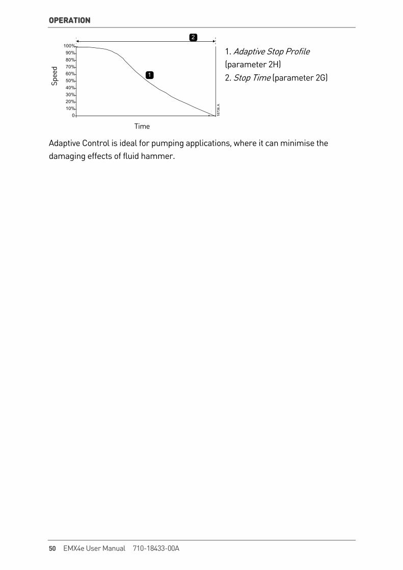
1. Adaptive Stop Profile (parameter 2H) 2. Stop Time (parameter 2G)
Time
Adaptive Control is ideal for pumping applications, where it can minimise the damaging effects of fluid hammer.
100%90%80%70%60%50%40%30%20%10%
0 1873
6.A
1
2
50 EMX4e User Manual 710-18433-00A
PROGRAMMABLE PARAMETERS
9. Programmable Parameters 9.1 Programming Menu The Programming Menu lets you view and change programmable parameters that control how the EMX4e operates.
To open the Programming Menu, press the MENU button while viewing the monitoring screens.
9.2 Altering Parameter Values To change a parameter value:
• scroll to the appropriate parameter in the Programming Menu and press to enter edit mode.
• to alter the parameter setting, use the and buttons. Pressing or once will increase or decrease the value by one unit. If the button is held for longer than five seconds, the value will increase or decrease at a faster rate.
• to save changes, press STORE. The setting shown on the display will be saved and the keypad will return to the parameter list.
• to cancel changes, press EXIT. The keypad will ask for confirmation, then return to the parameter list without saving changes.
9.3 Adjustment Lock You can prevent users from altering parameter settings by turning on the adjustment lock (parameter 10G Adjustment Lock).
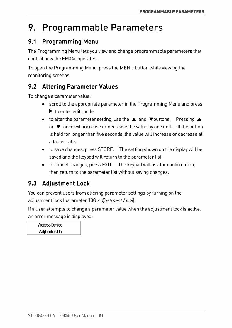
If a user attempts to change a parameter value when the adjustment lock is active, an error message is displayed:
Access Denied Adj Lock is On
710-18433-00A EMX4e User Manual 51
PROGRAMMABLE PARAMETERS
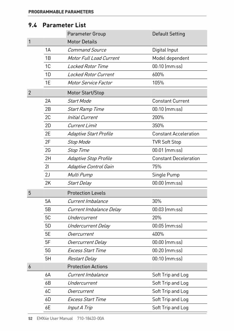
9.4 Parameter List Parameter Group Default Setting 1 Motor Details 1A Command Source Digital Input 1B Motor Full Load Current Model dependent 1C Locked Rotor Time 00:10 (mm:ss)
1D Locked Rotor Current 600%
1E Motor Service Factor 105%
2 Motor Start/Stop
2A Start Mode Constant Current
2B Start Ramp Time 00:10 (mm:ss)
2C Initial Current 200%
2D Current Limit 350%
2E Adaptive Start Profile Constant Acceleration
2F Stop Mode TVR Soft Stop
2G Stop Time 00:01 (mm:ss)
2H Adaptive Stop Profile Constant Deceleration
2I Adaptive Control Gain 75%
2J Multi Pump Single Pump
2K Start Delay 00:00 (mm:ss)
5 Protection Levels
5A Current Imbalance 30%
5B Current Imbalance Delay 00:03 (mm:ss)
5C Undercurrent 20%
5D Undercurrent Delay 00:05 (mm:ss)
5E Overcurrent 400%
5F Overcurrent Delay 00:00 (mm:ss)
5G Excess Start Time 00:20 (mm:ss)
5H Restart Delay 00:10 (mm:ss) 6 Protection Actions
6A Current Imbalance Soft Trip and Log
6B Undercurrent Soft Trip and Log
6C Overcurrent Soft Trip and Log
6D Excess Start Time Soft Trip and Log
6E Input A Trip Soft Trip and Log
52 EMX4e User Manual 710-18433-00A
PROGRAMMABLE PARAMETERS
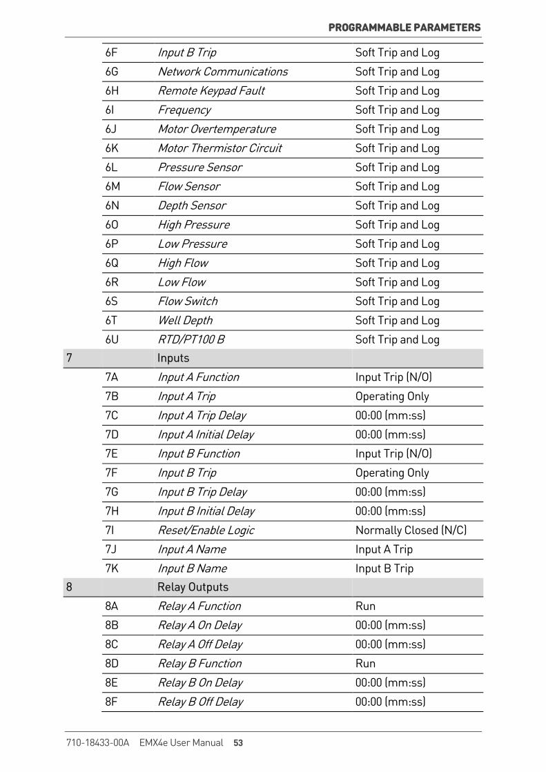
6F Input B Trip Soft Trip and Log
6G Network Communications Soft Trip and Log
6H Remote Keypad Fault Soft Trip and Log
6I Frequency Soft Trip and Log
6J Motor Overtemperature Soft Trip and Log
6K Motor Thermistor Circuit Soft Trip and Log
6L Pressure Sensor Soft Trip and Log
6M Flow Sensor Soft Trip and Log
6N Depth Sensor Soft Trip and Log
6O High Pressure Soft Trip and Log
6P Low Pressure Soft Trip and Log
6Q High Flow Soft Trip and Log
6R Low Flow Soft Trip and Log
6S Flow Switch Soft Trip and Log
6T Well Depth Soft Trip and Log
6U RTD/PT100 B Soft Trip and Log 7 Inputs
7A Input A Function Input Trip (N/O)
7B Input A Trip Operating Only
7C Input A Trip Delay 00:00 (mm:ss)
7D Input A Initial Delay 00:00 (mm:ss)
7E Input B Function Input Trip (N/O) 7F Input B Trip Operating Only 7G Input B Trip Delay 00:00 (mm:ss) 7H Input B Initial Delay 00:00 (mm:ss) 7I Reset/Enable Logic Normally Closed (N/C) 7J Input A Name Input A Trip 7K Input B Name Input B Trip 8 Relay Outputs 8A Relay A Function Run 8B Relay A On Delay 00:00 (mm:ss) 8C Relay A Off Delay 00:00 (mm:ss) 8D Relay B Function Run 8E Relay B On Delay 00:00 (mm:ss) 8F Relay B Off Delay 00:00 (mm:ss)
710-18433-00A EMX4e User Manual 53
PROGRAMMABLE PARAMETERS
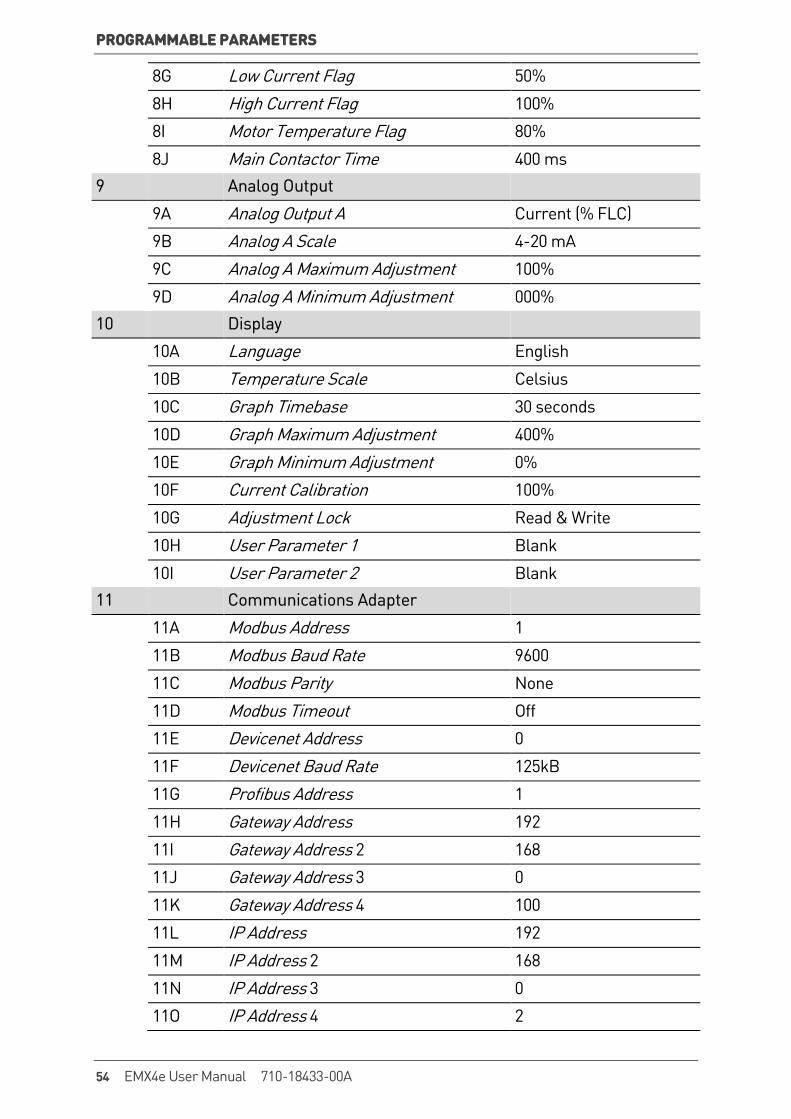
8G Low Current Flag 50% 8H High Current Flag 100% 8I Motor Temperature Flag 80% 8J Main Contactor Time 400 ms 9 Analog Output 9A Analog Output A Current (% FLC) 9B Analog A Scale 4-20 mA 9C Analog A Maximum Adjustment 100% 9D Analog A Minimum Adjustment 000% 10 Display 10A Language English 10B Temperature Scale Celsius 10C Graph Timebase 30 seconds 10D Graph Maximum Adjustment 400% 10E Graph Minimum Adjustment 0% 10F Current Calibration 100% 10G Adjustment Lock Read & Write 10H User Parameter 1 Blank 10I User Parameter 2 Blank 11 Communications Adapter 11A Modbus Address 1 11B Modbus Baud Rate 9600 11C Modbus Parity None 11D Modbus Timeout Off 11E Devicenet Address 0 11F Devicenet Baud Rate 125kB 11G Profibus Address 1 11H Gateway Address 192 11I Gateway Address 2 168 11J Gateway Address 3 0 11K Gateway Address 4 100 11L IP Address 192 11M IP Address 2 168 11N IP Address 3 0 11O IP Address 4 2
54 EMX4e User Manual 710-18433-00A
PROGRAMMABLE PARAMETERS
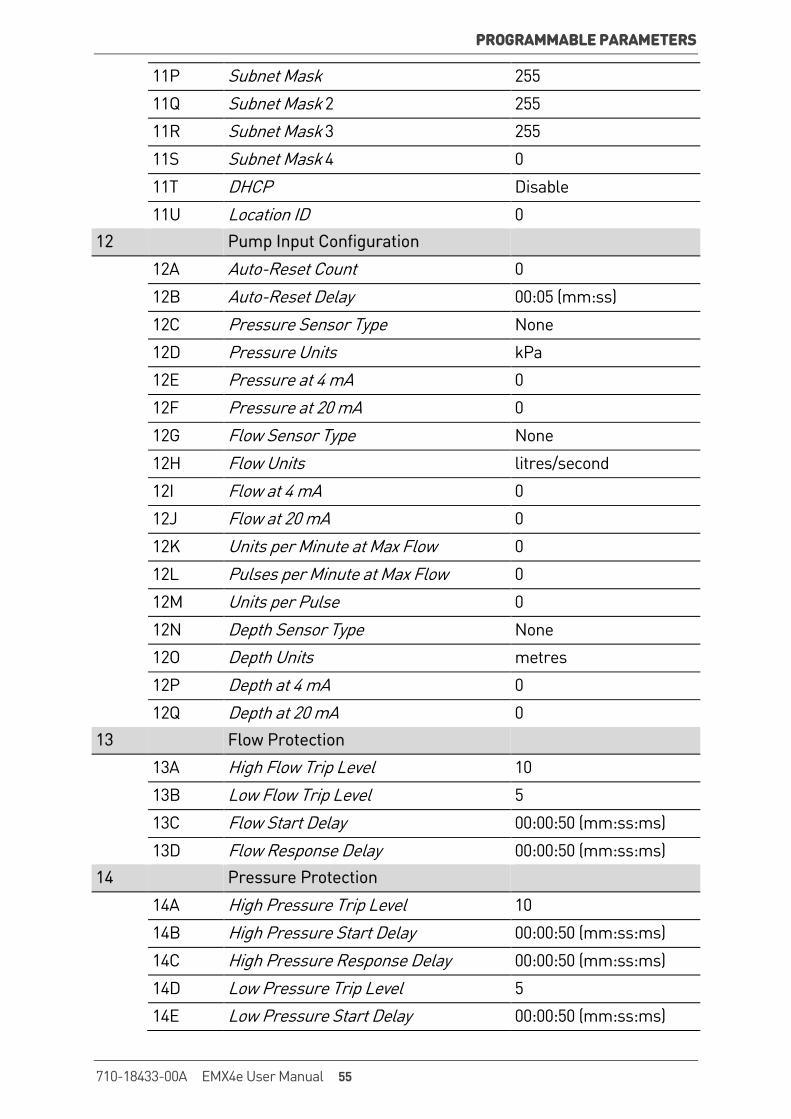
11P Subnet Mask 255 11Q Subnet Mask 2 255 11R Subnet Mask 3 255 11S Subnet Mask 4 0 11T DHCP Disable 11U Location ID 0 12 Pump Input Configuration 12A Auto-Reset Count 0 12B Auto-Reset Delay 00:05 (mm:ss) 12C Pressure Sensor Type None 12D Pressure Units kPa 12E Pressure at 4 mA 0 12F Pressure at 20 mA 0 12G Flow Sensor Type None 12H Flow Units litres/second 12I Flow at 4 mA 0 12J Flow at 20 mA 0 12K Units per Minute at Max Flow 0 12L Pulses per Minute at Max Flow 0 12M Units per Pulse 0 12N Depth Sensor Type None 12O Depth Units metres 12P Depth at 4 mA 0 12Q Depth at 20 mA 0 13 Flow Protection 13A High Flow Trip Level 10 13B Low Flow Trip Level 5 13C Flow Start Delay 00:00:50 (mm:ss:ms) 13D Flow Response Delay 00:00:50 (mm:ss:ms) 14 Pressure Protection 14A High Pressure Trip Level 10 14B High Pressure Start Delay 00:00:50 (mm:ss:ms) 14C High Pressure Response Delay 00:00:50 (mm:ss:ms) 14D Low Pressure Trip Level 5 14E Low Pressure Start Delay 00:00:50 (mm:ss:ms)
710-18433-00A EMX4e User Manual 55
PROGRAMMABLE PARAMETERS
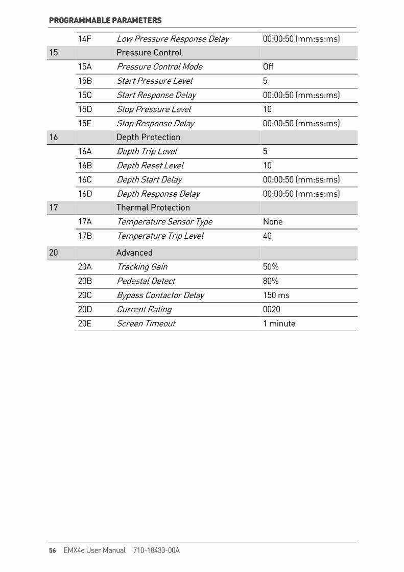
14F Low Pressure Response Delay 00:00:50 (mm:ss:ms) 15 Pressure Control 15A Pressure Control Mode Off 15B Start Pressure Level 5 15C Start Response Delay 00:00:50 (mm:ss:ms) 15D Stop Pressure Level 10 15E Stop Response Delay 00:00:50 (mm:ss:ms) 16 Depth Protection 16A Depth Trip Level 5 16B Depth Reset Level 10 16C Depth Start Delay 00:00:50 (mm:ss:ms) 16D Depth Response Delay 00:00:50 (mm:ss:ms) 17 Thermal Protection 17A Temperature Sensor Type None 17B Temperature Trip Level 40
20 Advanced 20A Tracking Gain 50% 20B Pedestal Detect 80% 20C Bypass Contactor Delay 150 ms 20D Current Rating 0020 20E Screen Timeout 1 minute
56 EMX4e User Manual 710-18433-00A
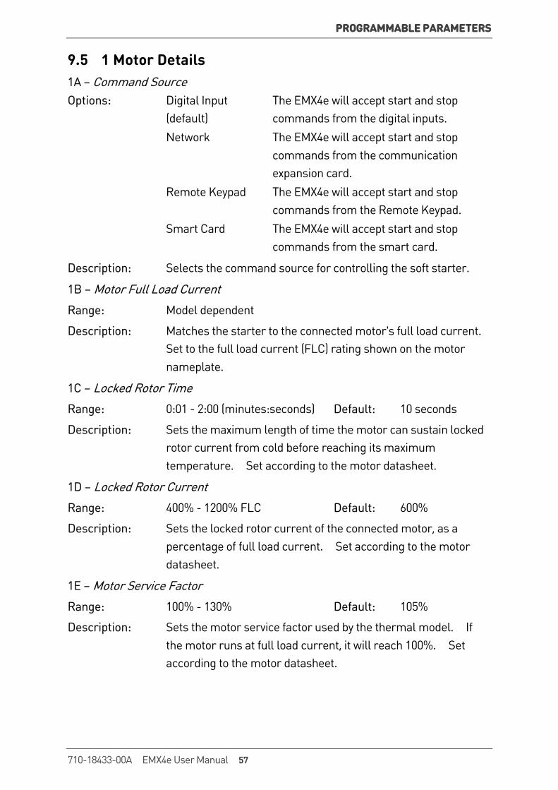
PROGRAMMABLE PARAMETERS
9.5 1 Motor Details 1A – Command Source Options: Digital Input
(default) The EMX4e will accept start and stop commands from the digital inputs.
Network The EMX4e will accept start and stop commands from the communication expansion card.
Remote Keypad The EMX4e will accept start and stop commands from the Remote Keypad.
Smart Card The EMX4e will accept start and stop commands from the smart card.
Description: Selects the command source for controlling the soft starter.
1B – Motor Full Load Current
Range: Model dependent
Description: Matches the starter to the connected motor's full load current. Set to the full load current (FLC) rating shown on the motor nameplate.
1C – Locked Rotor Time
Range: 0:01 - 2:00 (minutes:seconds) Default: 10 seconds
Description: Sets the maximum length of time the motor can sustain locked rotor current from cold before reaching its maximum temperature. Set according to the motor datasheet.
1D – Locked Rotor Current
Range: 400% - 1200% FLC Default: 600%
Description: Sets the locked rotor current of the connected motor, as a percentage of full load current. Set according to the motor datasheet.
1E – Motor Service Factor
Range: 100% - 130% Default: 105%
Description: Sets the motor service factor used by the thermal model. If the motor runs at full load current, it will reach 100%. Set according to the motor datasheet.
710-18433-00A EMX4e User Manual 57
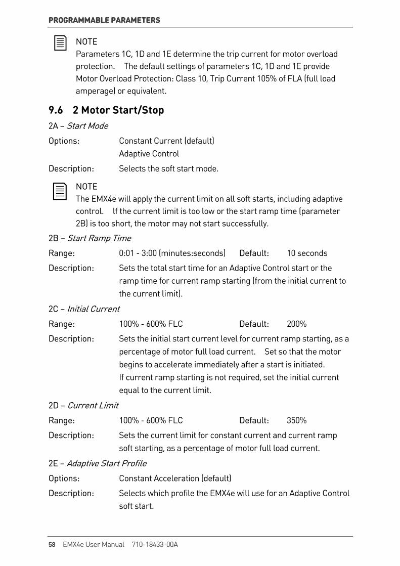
PROGRAMMABLE PARAMETERS
NOTE Parameters 1C, 1D and 1E determine the trip current for motor overload protection. The default settings of parameters 1C, 1D and 1E provide Motor Overload Protection: Class 10, Trip Current 105% of FLA (full load amperage) or equivalent.
9.6 2 Motor Start/Stop 2A – Start Mode
Options: Constant Current (default) Adaptive Control
Description: Selects the soft start mode.
NOTE The EMX4e will apply the current limit on all soft starts, including adaptive control. lf the current limit is too low or the start ramp time (parameter 2B) is too short, the motor may not start successfully.
2B – Start Ramp Time
Range: 0:01 - 3:00 (minutes:seconds) Default: 10 seconds
Description: Sets the total start time for an Adaptive Control start or the ramp time for current ramp starting (from the initial current to the current limit).
2C – Initial Current
Range: 100% - 600% FLC Default: 200%
Description: Sets the initial start current level for current ramp starting, as a percentage of motor full load current. Set so that the motor begins to accelerate immediately after a start is initiated. If current ramp starting is not required, set the initial current equal to the current limit.
2D – Current Limit
Range: 100% - 600% FLC Default: 350%
Description: Sets the current limit for constant current and current ramp soft starting, as a percentage of motor full load current.
2E – Adaptive Start Profile
Options: Constant Acceleration (default)
Description: Selects which profile the EMX4e will use for an Adaptive Control soft start.
58 EMX4e User Manual 710-18433-00A
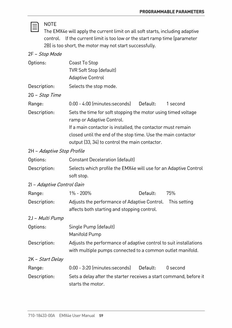
PROGRAMMABLE PARAMETERS
NOTE The EMX4e will apply the current limit on all soft starts, including adaptive control. lf the current limit is too low or the start ramp time (parameter 2B) is too short, the motor may not start successfully.
2F – Stop Mode
Options: Coast To Stop TVR Soft Stop (default) Adaptive Control
Description: Selects the stop mode.
2G – Stop Time
Range: 0:00 - 4:00 (minutes:seconds) Default: 1 second
Description: Sets the time for soft stopping the motor using timed voltage ramp or Adaptive Control. If a main contactor is installed, the contactor must remain closed until the end of the stop time. Use the main contactor output (33, 34) to control the main contactor.
2H – Adaptive Stop Profile
Options: Constant Deceleration (default)
Description: Selects which profile the EMX4e will use for an Adaptive Control soft stop.
2I – Adaptive Control Gain
Range: 1% - 200% Default: 75%
Description: Adjusts the performance of Adaptive Control. This setting affects both starting and stopping control.
2J – Multi Pump
Options: Single Pump (default) Manifold Pump
Description: Adjusts the performance of adaptive control to suit installations with multiple pumps connected to a common outlet manifold.
2K – Start Delay
Range: 0:00 - 3:20 (minutes:seconds) Default: 0 second
Description: Sets a delay after the starter receives a start command, before it starts the motor.
710-18433-00A EMX4e User Manual 59
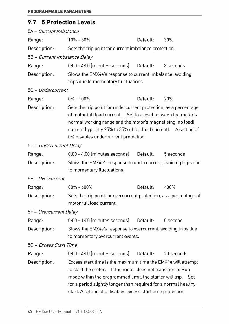
PROGRAMMABLE PARAMETERS
9.7 5 Protection Levels 5A – Current Imbalance
Range: 10% - 50% Default: 30%
Description: Sets the trip point for current imbalance protection.
5B – Current Imbalance Delay
Range: 0:00 - 4:00 (minutes:seconds) Default: 3 seconds
Description: Slows the EMX4e's response to current imbalance, avoiding trips due to momentary fluctuations.
5C – Undercurrent
Range: 0% - 100% Default: 20%
Description: Sets the trip point for undercurrent protection, as a percentage of motor full load current. Set to a level between the motor's normal working range and the motor's magnetising (no load) current (typically 25% to 35% of full load current). A setting of 0% disables undercurrent protection.
5D – Undercurrent Delay
Range: 0:00 - 4:00 (minutes:seconds) Default: 5 seconds
Description: Slows the EMX4e's response to undercurrent, avoiding trips due to momentary fluctuations.
5E – Overcurrent
Range: 80% - 600% Default: 400%
Description: Sets the trip point for overcurrent protection, as a percentage of motor full load current.
5F – Overcurrent Delay
Range: 0:00 - 1:00 (minutes:seconds) Default: 0 second
Description: Slows the EMX4e's response to overcurrent, avoiding trips due to momentary overcurrent events.
5G – Excess Start Time
Range: 0:00 - 4:00 (minutes:seconds) Default: 20 seconds
Description: Excess start time is the maximum time the EMX4e will attempt to start the motor. If the motor does not transition to Run mode within the programmed limit, the starter will trip. Set for a period slightly longer than required for a normal healthy start. A setting of 0 disables excess start time protection.
60 EMX4e User Manual 710-18433-00A

PROGRAMMABLE PARAMETERS
5H – Restart Delay
Range: 00:01 - 60:00 (minutes:seconds) Default: 10 seconds
Description: The EMX4e can be configured to force a delay between the end of a stop and the beginning of the next start. During the restart delay period, the display shows the time remaining before another start can be attempted.
9.8 6 Protection Action 6A – Current Imbalance Options: Soft Trip and Log
(default) The soft starter will stop the motor as selected in parameter 2F Stop Mode, then enter trip state. The trip must be reset before the EMX4e can restart.
Trip Starter The soft starter will remove power and the motor will coast to stop. The trip must be reset before the EMX4e can restart.
Warn and Log The protection will be written to the event log and the display will show a warning message, but the soft starter will continue to operate.
Log Only The protection will be written to the event log but the soft starter will continue to operate.
Description: Selects the soft starter's response to each protection. All protection events are written to the event log.
6B – Undercurrent
Options: Soft Trip and Log (default) Warn and Log Trip Starter Log Only
Description: Selects the soft starter's response to the protection event.
6C – Overcurrent
Options: Soft Trip and Log (default) Warn and Log Trip Starter Log Only
Description: Selects the soft starter's response to the protection event.
6D – Excess Start Time
Options: Soft Trip and Log (default) Warn and Log Trip Starter Log Only
Description: Selects the soft starter's response to the protection event.
710-18433-00A EMX4e User Manual 61
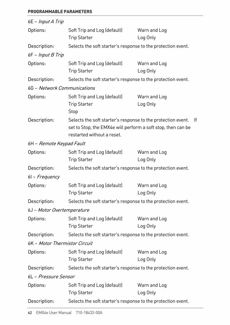
PROGRAMMABLE PARAMETERS
6E – Input A Trip
Options: Soft Trip and Log (default) Warn and Log Trip Starter Log Only
Description: Selects the soft starter's response to the protection event.
6F – Input B Trip
Options: Soft Trip and Log (default) Warn and Log Trip Starter Log Only
Description: Selects the soft starter's response to the protection event.
6G – Network Communications
Options: Soft Trip and Log (default) Warn and Log Trip Starter Log Only Stop
Description: Selects the soft starter's response to the protection event. If set to Stop, the EMX4e will perform a soft stop, then can be restarted without a reset.
6H – Remote Keypad Fault
Options: Soft Trip and Log (default) Warn and Log Trip Starter Log Only
Description: Selects the soft starter's response to the protection event.
6I – Frequency
Options: Soft Trip and Log (default) Warn and Log Trip Starter Log Only
Description: Selects the soft starter's response to the protection event.
6J – Motor Overtemperature
Options: Soft Trip and Log (default) Warn and Log Trip Starter Log Only
Description: Selects the soft starter's response to the protection event.
6K – Motor Thermistor Circuit
Options: Soft Trip and Log (default) Warn and Log Trip Starter Log Only
Description: Selects the soft starter's response to the protection event.
6L – Pressure Sensor
Options: Soft Trip and Log (default) Warn and Log Trip Starter Log Only
Description: Selects the soft starter's response to the protection event.
62 EMX4e User Manual 710-18433-00A
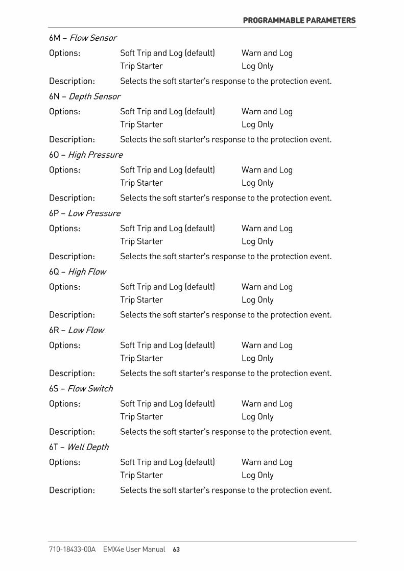
PROGRAMMABLE PARAMETERS
6M – Flow Sensor
Options: Soft Trip and Log (default) Warn and Log Trip Starter Log Only
Description: Selects the soft starter's response to the protection event.
6N – Depth Sensor
Options: Soft Trip and Log (default) Warn and Log Trip Starter Log Only
Description: Selects the soft starter's response to the protection event.
6O – High Pressure
Options: Soft Trip and Log (default) Warn and Log Trip Starter Log Only
Description: Selects the soft starter's response to the protection event.
6P – Low Pressure
Options: Soft Trip and Log (default) Warn and Log Trip Starter Log Only
Description: Selects the soft starter's response to the protection event.
6Q – High Flow
Options: Soft Trip and Log (default) Warn and Log Trip Starter Log Only
Description: Selects the soft starter's response to the protection event.
6R – Low Flow
Options: Soft Trip and Log (default) Warn and Log Trip Starter Log Only
Description: Selects the soft starter's response to the protection event.
6S – Flow Switch
Options: Soft Trip and Log (default) Warn and Log Trip Starter Log Only
Description: Selects the soft starter's response to the protection event.
6T – Well Depth
Options: Soft Trip and Log (default) Warn and Log Trip Starter Log Only
Description: Selects the soft starter's response to the protection event.
710-18433-00A EMX4e User Manual 63
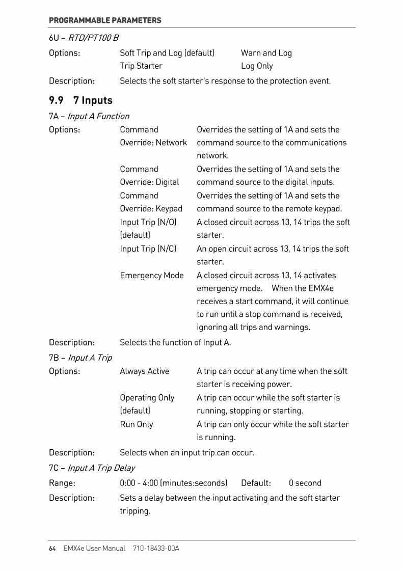
PROGRAMMABLE PARAMETERS
6U – RTD/PT100 B
Options: Soft Trip and Log (default) Warn and Log Trip Starter Log Only
Description: Selects the soft starter's response to the protection event.
9.9 7 Inputs 7A – Input A Function Options: Command
Override: Network Overrides the setting of 1A and sets the command source to the communications network.
Command Override: Digital
Overrides the setting of 1A and sets the command source to the digital inputs.
Command Override: Keypad
Overrides the setting of 1A and sets the command source to the remote keypad.
Input Trip (N/O) (default)
A closed circuit across 13, 14 trips the soft starter.
Input Trip (N/C) An open circuit across 13, 14 trips the soft starter.
Emergency Mode A closed circuit across 13, 14 activates emergency mode. When the EMX4e receives a start command, it will continue to run until a stop command is received, ignoring all trips and warnings.
Description: Selects the function of Input A.
7B – Input A Trip Options: Always Active A trip can occur at any time when the soft
starter is receiving power. Operating Only
(default) A trip can occur while the soft starter is running, stopping or starting.
Run Only A trip can only occur while the soft starter is running.
Description: Selects when an input trip can occur.
7C – Input A Trip Delay
Range: 0:00 - 4:00 (minutes:seconds) Default: 0 second
Description: Sets a delay between the input activating and the soft starter tripping.
64 EMX4e User Manual 710-18433-00A
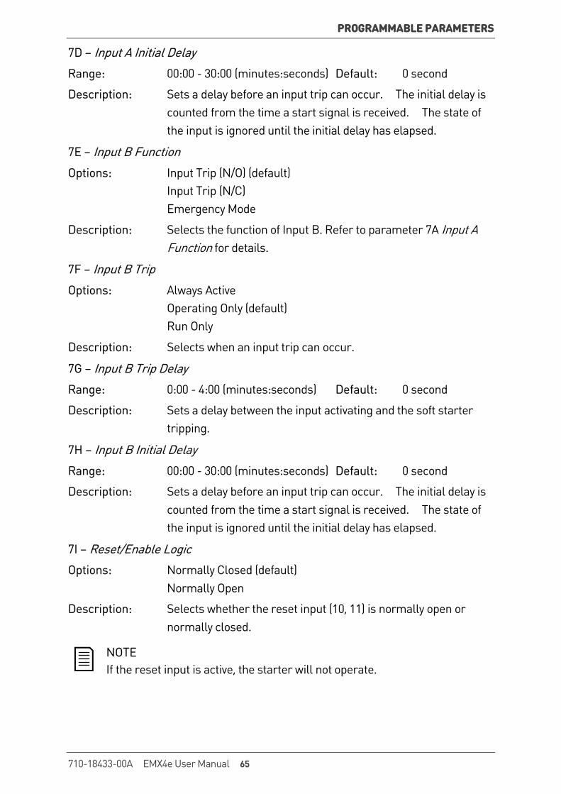
PROGRAMMABLE PARAMETERS
7D – Input A Initial Delay
Range: 00:00 - 30:00 (minutes:seconds) Default: 0 second
Description: Sets a delay before an input trip can occur. The initial delay is counted from the time a start signal is received. The state of the input is ignored until the initial delay has elapsed.
7E – Input B Function
Options: Input Trip (N/O) (default) Input Trip (N/C) Emergency Mode
Description: Selects the function of Input B. Refer to parameter 7A Input A Function for details.
7F – Input B Trip
Options: Always Active Operating Only (default) Run Only
Description: Selects when an input trip can occur.
7G – Input B Trip Delay
Range: 0:00 - 4:00 (minutes:seconds) Default: 0 second
Description: Sets a delay between the input activating and the soft starter tripping.
7H – Input B Initial Delay
Range: 00:00 - 30:00 (minutes:seconds) Default: 0 second
Description: Sets a delay before an input trip can occur. The initial delay is counted from the time a start signal is received. The state of the input is ignored until the initial delay has elapsed.
7I – Reset/Enable Logic
Options: Normally Closed (default) Normally Open
Description: Selects whether the reset input (10, 11) is normally open or normally closed.
NOTE If the reset input is active, the starter will not operate.
710-18433-00A EMX4e User Manual 65
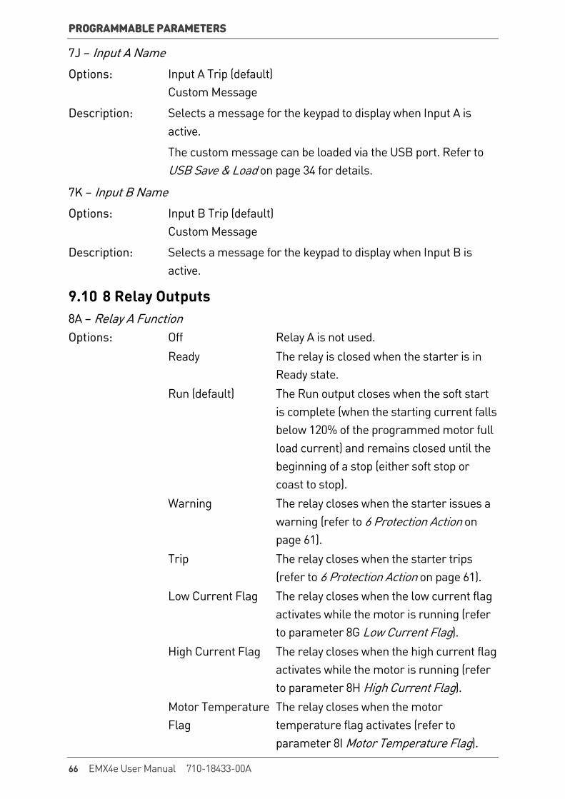
PROGRAMMABLE PARAMETERS
7J – Input A Name
Options: Input A Trip (default) Custom Message
Description: Selects a message for the keypad to display when Input A is active.
The custom message can be loaded via the USB port. Refer to USB Save & Load on page 34 for details.
7K – Input B Name
Options: Input B Trip (default) Custom Message
Description: Selects a message for the keypad to display when Input B is active.
9.10 8 Relay Outputs 8A – Relay A Function Options: Off Relay A is not used. Ready The relay is closed when the starter is in
Ready state. Run (default) The Run output closes when the soft start
is complete (when the starting current falls below 120% of the programmed motor full load current) and remains closed until the beginning of a stop (either soft stop or coast to stop).
Warning The relay closes when the starter issues a warning (refer to 6 Protection Action on page 61).
Trip The relay closes when the starter trips (refer to 6 Protection Action on page 61).
Low Current Flag The relay closes when the low current flag activates while the motor is running (refer to parameter 8G Low Current Flag).
High Current Flag The relay closes when the high current flag activates while the motor is running (refer to parameter 8H High Current Flag).
Motor Temperature Flag
The relay closes when the motor temperature flag activates (refer to parameter 8I Motor Temperature Flag).
66 EMX4e User Manual 710-18433-00A
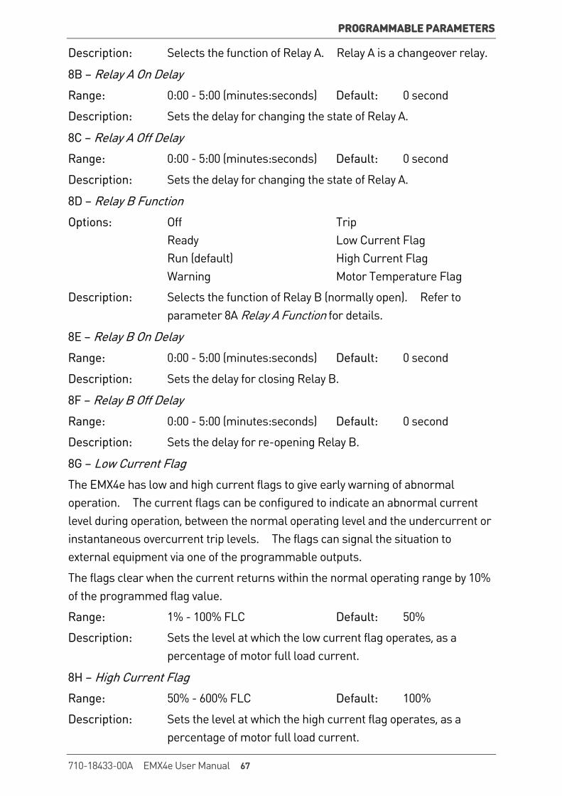
PROGRAMMABLE PARAMETERS
Description: Selects the function of Relay A. Relay A is a changeover relay.
8B – Relay A On Delay
Range: 0:00 - 5:00 (minutes:seconds) Default: 0 second
Description: Sets the delay for changing the state of Relay A.
8C – Relay A Off Delay
Range: 0:00 - 5:00 (minutes:seconds) Default: 0 second
Description: Sets the delay for changing the state of Relay A.
8D – Relay B Function
Options: Off Trip Ready Low Current Flag Run (default) High Current Flag Warning Motor Temperature Flag
Description: Selects the function of Relay B (normally open). Refer to parameter 8A Relay A Function for details.
8E – Relay B On Delay
Range: 0:00 - 5:00 (minutes:seconds) Default: 0 second
Description: Sets the delay for closing Relay B.
8F – Relay B Off Delay
Range: 0:00 - 5:00 (minutes:seconds) Default: 0 second
Description: Sets the delay for re-opening Relay B.
8G – Low Current Flag
The EMX4e has low and high current flags to give early warning of abnormal operation. The current flags can be configured to indicate an abnormal current level during operation, between the normal operating level and the undercurrent or instantaneous overcurrent trip levels. The flags can signal the situation to external equipment via one of the programmable outputs.
The flags clear when the current returns within the normal operating range by 10% of the programmed flag value.
Range: 1% - 100% FLC Default: 50%
Description: Sets the level at which the low current flag operates, as a percentage of motor full load current.
8H – High Current Flag
Range: 50% - 600% FLC Default: 100%
Description: Sets the level at which the high current flag operates, as a percentage of motor full load current.
710-18433-00A EMX4e User Manual 67
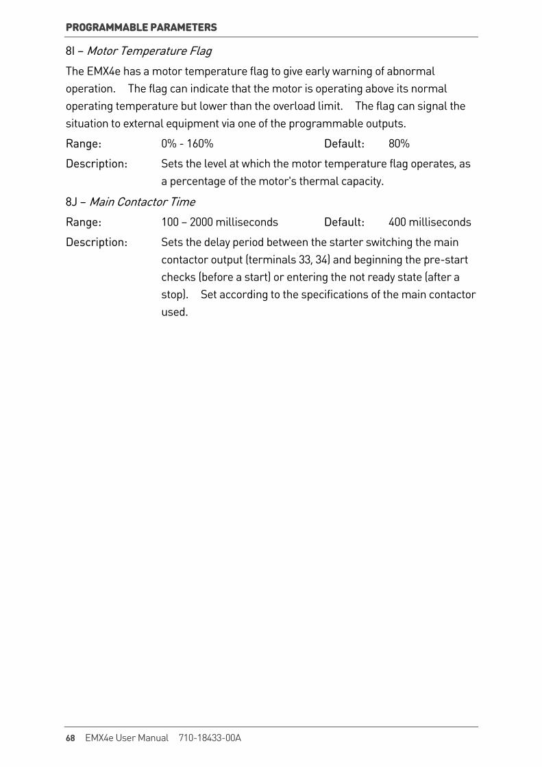
PROGRAMMABLE PARAMETERS
8I – Motor Temperature Flag
The EMX4e has a motor temperature flag to give early warning of abnormal operation. The flag can indicate that the motor is operating above its normal operating temperature but lower than the overload limit. The flag can signal the situation to external equipment via one of the programmable outputs.
Range: 0% - 160% Default: 80%
Description: Sets the level at which the motor temperature flag operates, as a percentage of the motor's thermal capacity.
8J – Main Contactor Time
Range: 100 – 2000 milliseconds Default: 400 milliseconds
Description: Sets the delay period between the starter switching the main contactor output (terminals 33, 34) and beginning the pre-start checks (before a start) or entering the not ready state (after a stop). Set according to the specifications of the main contactor used.
68 EMX4e User Manual 710-18433-00A

PROGRAMMABLE PARAMETERS
9.11 9 Analog Output 9A – Analog Output A Options: Current (% FLC)
(default) Current as a percentage of motor full load current.
Motor Temp (%) The motor's temperature, calculated by the thermal model.
Heatsink Temperature (°C)
The soft starter's temperature, measured at the heatsink.
Motor pf Motor power factor, measured by the soft starter.
Description: Selects which information will be reported via the analog output.
9B – Analog A Scale
Range: 0-20 mA 4-20 mA (default)
Description: Selects the range of the analog output.
9C – Analog A Maximum Adjustment
Range: 0% - 600% Default: 100%
Description: Calibrates the upper limit of the analog output to match the signal measured on an external current measuring device.
9D – Analog A Minimum Adjustment
Range: 0% - 600% Default: 0%
Description: Calibrates the lower limit of the analog output to match the signal measured on an external current measuring device.
9.12 10 Display 10A – Language
Options: English (default) Português Chinese Français Español Italiano Deutsch Russian
Description: Selects which language the keypad will use to display messages and feedback.
710-18433-00A EMX4e User Manual 69

PROGRAMMABLE PARAMETERS
10B – Temperature Scale
Options: Celsius (default) Fahrenheit
Description: Selects whether the EMX4e will display temperatures in degrees Celsius or Fahrenheit.
10C – Graph Timebase
Options: 30 seconds (default) 1 minute 30 minutes 1 hour
Description: Sets the graph time scale. The graph will progressively replace the old data with new data.
10D – Graph Maximum Adjustment
Range: 0% – 600% Default: 400%
Description: Adjusts the upper limit of the performance graph.
10E – Graph Minimum Adjustment
Range: 0% – 600% Default: 0%
Description: Adjusts the lower limit of the performance graph.
10F – Current Calibration
Range: 85% - 115% Default: 100%
Description: Calibrates the soft starter's current monitoring circuits to match an external current metering device. Use the following formula to determine the necessary adjustment:
Calibration (%) = Current shown on EMX4e display
Current measured by external device
10G – Adjustment Lock Options: Read & Write
(default) Allows users to alter parameter values in the Programming Menu.
Read Only Prevents users altering parameter values in the Programming Menu. Parameter values can still be viewed.
Description: Selects whether the keypad will allow parameters to be changed via the Programming Menu.
70 EMX4e User Manual 710-18433-00A
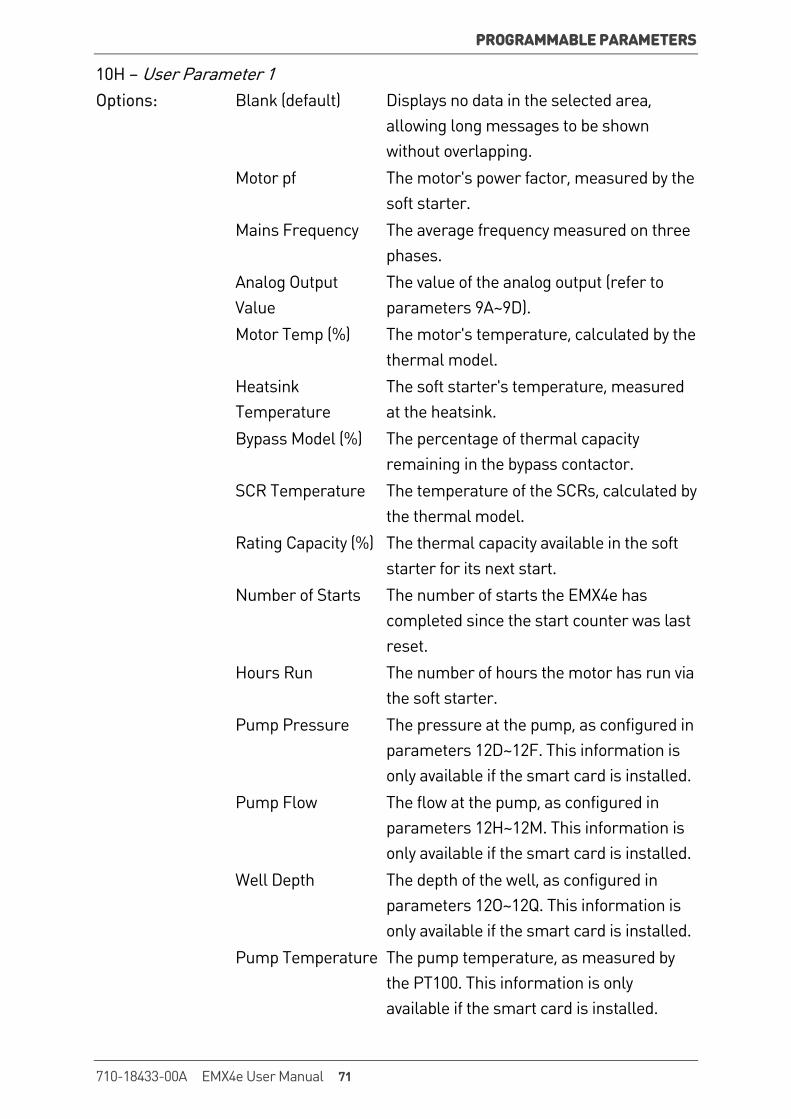
PROGRAMMABLE PARAMETERS
10H – User Parameter 1 Options: Blank (default) Displays no data in the selected area,
allowing long messages to be shown without overlapping.
Motor pf The motor's power factor, measured by the soft starter.
Mains Frequency The average frequency measured on three phases.
Analog Output Value
The value of the analog output (refer to parameters 9A~9D).
Motor Temp (%) The motor's temperature, calculated by the thermal model.
Heatsink Temperature
The soft starter's temperature, measured at the heatsink.
Bypass Model (%) The percentage of thermal capacity remaining in the bypass contactor.
SCR Temperature The temperature of the SCRs, calculated by the thermal model.
Rating Capacity (%) The thermal capacity available in the soft starter for its next start.
Number of Starts The number of starts the EMX4e has completed since the start counter was last reset.
Hours Run The number of hours the motor has run via the soft starter.
Pump Pressure The pressure at the pump, as configured in parameters 12D~12F. This information is only available if the smart card is installed.
Pump Flow The flow at the pump, as configured in parameters 12H~12M. This information is only available if the smart card is installed.
Well Depth The depth of the well, as configured in parameters 12O~12Q. This information is only available if the smart card is installed.
Pump Temperature The pump temperature, as measured by the PT100. This information is only available if the smart card is installed.
710-18433-00A EMX4e User Manual 71

PROGRAMMABLE PARAMETERS
Description: Selects which information will be displayed on the programmable monitoring screen.
10I – User Parameter 2 Options: Blank (default) Rating Capacity (%) Motor pf Number of Starts Mains Frequency Hours Run Analog Output Value Pump Pressure Motor Temp (%) Pump Flow Heatsink Temperature Well Depth Bypass Model (%) Pump Temperature SCR Temperature
Description: Selects which information will be displayed on the programmable monitoring screen. Refer to parameter 10H User Parameter 1 for details.
9.13 11 Communications Adapter 11A – Modbus Address
Range: 1 - 254 Default: 1
Description: Sets the Modbus RTU network address for the soft starter.
11B – Modbus Baud Rate
Options: 4800 9600 (default) 19200 38400
Description: Selects the baud rate for Modbus RTU communications.
11C – Modbus Parity
Options: None (default) Odd Even 10-bit
Description: Selects the parity for Modbus RTU communications.
72 EMX4e User Manual 710-18433-00A

PROGRAMMABLE PARAMETERS
11D – Modbus Timeout
Options: Off (default) 10 seconds 60 seconds 100 seconds
Description: Selects the timeout for Modbus RTU communications.
11E – Devicenet Address
Range: 0 - 63 Default: 0
Description: Sets the DeviceNet network address for the soft starter.
11F – Devicenet Baud Rate
Options: 125 kB (default) 250 kB 500 kB
Description: Selects the baud rate for DeviceNet communications.
11G – Profibus Address
Range: 1 - 125 Default: 1
Description: Sets the Profibus network address for the soft starter.
11H – Gateway Address
Range: 0 - 255 Default: 192
Description: Sets the first component of the network gateway address. The gateway address is set using parameters 11H~11K and the default address is 192.168.0.100.
11I – Gateway Address 2
Range: 0 - 255 Default: 168
Description: Sets the second component of the network gateway address.
11J – Gateway Address 3
Range: 0 - 255 Default: 0
Description: Sets the third component of the network gateway address.
11K – Gateway Address 4
Range: 0 - 255 Default: 100
Description: Sets the fourth component of the network gateway address.
NOTE The network address can also be set via the Network Address options in the Setup Tools. Refer to Network Address on page 36 for details.
710-18433-00A EMX4e User Manual 73

PROGRAMMABLE PARAMETERS
11L – IP Address
Range: 0 - 255 Default: 192
Description: Sets the first component of the soft starter's IP address, for Ethernet communications. The IP address is set using parameters 11L~11O and the default address is 192.168.0.2.
11M – IP Address 2
Range: 0 - 255 Default: 168
Description: Sets the second component of the soft starter's IP address, for Ethernet communications.
11N – IP Address 3
Range: 0 - 255 Default: 0
Description: Sets the third component of the soft starter's IP address, for Ethernet communications.
11O – IP Address 4
Range: 0 - 255 Default: 2
Description: Sets the fourth component of the soft starter's IP address, for Ethernet communications.
NOTE The network address can also be set via the Network Address options in the Setup Tools. Refer to Network Address on page 36 for details.
11P – Subnet Mask
Range: 0 - 255 Default: 255
Description: Sets the first component of the network subnet mask, for Ethernet communications. The subnet mask is set using parameters 11P~11S and the default mask is 255.255.255.0.
11Q – Subnet Mask 2
Range: 0 - 255 Default: 255
Description: Sets the second component of the network subnet mask, for Ethernet communications.
11R – Subnet Mask 3
Range: 0 - 255 Default: 255
Description: Sets the third component of the network subnet mask, for Ethernet communications.
74 EMX4e User Manual 710-18433-00A
PROGRAMMABLE PARAMETERS
11S – Subnet Mask 4
Range: 0 - 255 Default: 0
Description: Sets the fourth component of the network subnet mask, for Ethernet communications.
NOTE The network address can also be set via the Network Address options in the Setup Tools. Refer to Network Address on page 36 for details.
11T – DHCP
Options: Disable (default) Enable
Description: Selects whether the communications card will accept an IP address assigned by DHCP.
NOTE DHCP addressing is available with Modbus TCP and Ethernet/IP. DHCP addressing is not supported with Profinet.
11U – Location ID
Range: 0 - 65535 Default: 0
Description: Sets the soft starter's unique location ID.
9.14 12 Pump Input Configuration
NOTE The parameters in this group are only active if a smart card is installed.
12A – Auto-Reset Count
Range: 0 – 5 Default: 0
Description: Sets how many times the soft starter will auto-reset, if it continues to trip. The reset counter increases by one each time the soft starter auto-resets, and resets to zero after a successful start.
12B – Auto-Reset Delay
Range: 0:05 - 30:00 (minutes:seconds) Default: 5 seconds
Description: Sets a delay before the EMX4e will auto-reset a trip.
710-18433-00A EMX4e User Manual 75
PROGRAMMABLE PARAMETERS
12C – Pressure Sensor Type
Options: None (default) Switch Analog
Description: Selects which type of sensor is associated with the pressure sensor input on the smart card.
12D – Pressure Units
Options: Bar kPa (default) Psi
Description: Selects which units the sensor will use to report the measured pressure.
12E – Pressure at 4 mA
Range: 0 – 5000 Default: 0
Description: Calibrates the soft starter to the 4 mA (0%) level of the pressure sensor input.
12F – Pressure at 20 mA
Range: 0 – 5000 Default: 0
Description: Calibrates the soft starter to the 20 mA (100%) level of the pressure sensor input.
12G – Flow Sensor Type
Options: None (default) Pulses per minute Switch Pulses per unit Analog
Description: Selects which type of sensor is associated with the flow sensor input on the smart card.
12H – Flow Units
Options: litres/second (default) litres/minute gallons/second gallons/minute
Description: Selects which units the sensor will use to report the measured flow.
76 EMX4e User Manual 710-18433-00A
PROGRAMMABLE PARAMETERS
12I – Flow at 4 mA
Range: 0 – 5000 Default: 0
Description: Calibrates the soft starter to the 4 mA (0%) level of the flow sensor input.
12J – Flow at 20 mA
Range: 0 – 5000 Default: 0
Description: Calibrates the soft starter to the 20 mA (100%) level of the flow sensor input.
12K – Units per Minute at Max Flow
Range: 0 – 5000 Default: 0
Description: Calibrates the soft starter to the maximum flow volume of the flow sensor.
12L – Pulses per Minute at Max Flow
Range: 0 – 20000 Default: 0
Description: Calibrates the soft starter to the maximum flow volume of the flow sensor.
12M – Units per Pulse
Range: 0 – 1000 Default: 0
Description: Set to match how many units the flow sensor will measure for each pulse.
12N – Depth Sensor Type
Options: None (default) Switch Analog
Description: Selects which type of sensor is associated with the depth sensor input on the smart card.
12O – Depth Units
Options: metres (default) feet
Description: Selects which units the sensor will use to report the measured depth.
12P – Depth at 4 mA
Range: 0 – 1000 Default: 0
Description: Calibrates the soft starter to the 4 mA (0%) level of the depth sensor input.
710-18433-00A EMX4e User Manual 77
PROGRAMMABLE PARAMETERS
12Q – Depth at 20 mA
Range: 0 – 1000 Default: 0
Description: Calibrates the soft starter to the 20 mA (100%) level of the depth sensor input.
9.15 13 Flow Protection
NOTE The parameters in this group are only active if a smart card is installed.
Flow protection uses terminals B33, B34 or C23, C24 on the smart card.
13A – High Flow Trip Level
Range: 0 – 5000 Default: 10
Description: Sets the trip point for high flow protection.
13B – Low Flow Trip Level
Range: 1 – 5000 Default: 5
Description: Sets the trip point for low flow protection.
13C – Flow Start Delay
Range: 00:00:50 – 30:00:00 (mm:ss:ms) Default: 0.5 seconds
Description: Sets a delay before a flow protection trip can occur. The delay is counted from the time a start signal is received. The flow level is ignored until the start delay has elapsed.
13D – Flow Response Delay
Range: 00:00:10 – 30:00:00 (mm:ss:ms) Default: 0.5 seconds
Description: Sets a delay between the flow passing the high or low flow trip levels, and the soft starter tripping.
9.16 14 Pressure Protection
NOTE The parameters in this group are only active if a smart card is installed.
Pressure protection use terminals B23, B24 or C33, C34, C43, C44 on the smart card.
14A – High Pressure Trip Level
Range: 0 – 5000 Default: 10
Description: Sets the trip point for high pressure protection.
78 EMX4e User Manual 710-18433-00A
PROGRAMMABLE PARAMETERS
14B – High Pressure Start Delay
Range: 00:00:10 – 30:00:00 (mm:ss:ms) Default: 0.5 seconds
Description: Sets a delay before a high pressure protection trip can occur. The delay is counted from the time a start signal is received. The pressure is ignored until the start delay has elapsed.
14C – High Pressure Response Delay
Range: 00:00:10 – 30:00:00 (mm:ss:ms) Default: 0.5 seconds
Description: Sets a delay between the pressure passing the high pressure trip level, and the soft starter tripping.
14D – Low Pressure Trip Level
Range: 0 – 5000 Default: 5
Description: Sets the trip point for high pressure protection.
14E – Low Pressure Start Delay
Range: 00:00:10 – 30:00:00 (mm:ss:ms) Default: 0.5 seconds
Description: Sets a delay before a low pressure protection trip can occur. The delay is counted from the time a start signal is received. The pressure is ignored until the start delay has elapsed.
14F – Low Pressure Response Delay
Range: 00:00:10 – 30:00:00 (mm:ss:ms) Default: 0.5 seconds
Description: Sets a delay between the pressure passing the low pressure trip level, and the soft starter tripping.
710-18433-00A EMX4e User Manual 79

PROGRAMMABLE PARAMETERS
9.17 15 Pressure Control Pressure control use terminals B23, B24 (sensor 2) on the smart card.
NOTE The parameters in this group are only active if a smart card is installed.
15A – Pressure Control Mode Options: Off (default) The EMX4e will not use the pressure
sensor to control soft starting. Falling Pressure
Start The EMX4e will start when the pressure drops below the level selected in parameter 15B Start Pressure Level.
Rising Pressure Start
The EMX4e will start when the pressure rises above the level selected in parameter 15B Start Pressure Level.
Description: Selects how the EMX4e will use data from the pressure sensor to control the motor.
15B – Start Pressure Level
Range: 1 – 5000 Default: 5
Description: Sets the pressure level to trigger the EMX4e to perform a soft start.
15C – Start Response Delay
Range: 00:00:10 – 30:00:00 (mm:ss:ms) Default: 0.5 seconds
Description: Sets a delay between the pressure passing the pressure control start level, and the EMX4e performing a soft start.
15D – Stop Pressure Level
Range: 0 – 5000 Default: 10
Description: Sets the pressure level to trigger the EMX4e to stop the motor.
15E – Stop Response Delay
Range: 00:00:10 – 30:00:00 (mm:ss:ms) Default: 0.5 seconds
Description: Sets a delay between the pressure passing the pressure control stop level, and the EMX4e stopping the motor.
80 EMX4e User Manual 710-18433-00A
PROGRAMMABLE PARAMETERS
9.18 16 Depth Protection
NOTE The parameters in this group are only active if a smart card is installed.
Depth protection uses terminals B13, B14 or C13, C14 on the smart card.
16A – Depth Trip Level
Range: 0 – 1000 Default: 5
Description: Sets the trip point for depth protection.
16B – Depth Reset Level
Range: 0 – 1000 Default: 10
Description: Sets the level for the EMX4e to auto-reset a depth trip.
16C – Depth Start Delay
Range: 00:00:10 – 30:00:00 (mm:ss:ms) Default: 0.5 seconds
Description: Sets a delay before a depth protection trip can occur. The delay is counted from the time a start signal is received. The depth input is ignored until the start delay has elapsed.
16D – Depth Response Delay
Range: 00:00:10 – 30:00:00 (mm:ss:ms) Default: 0.5 seconds
Description: Sets a delay between the depth passing the depth protection trip level, and the soft starter tripping.
9.19 17 Thermal Protection
NOTE The parameters in this group are only active if a smart card is installed.
17A – Temperature Sensor Type
Options: None (default) PT100
Description: Selects which type of sensor is associated with the temperature sensor input on the smart card.
17B – Temperature Trip Level
Range: 0° – 240° Default: 40°
Description: Sets the trip point for temperature protection. Use parameter 10B Temperature Scale to configure the temperature scale.
710-18433-00A EMX4e User Manual 81
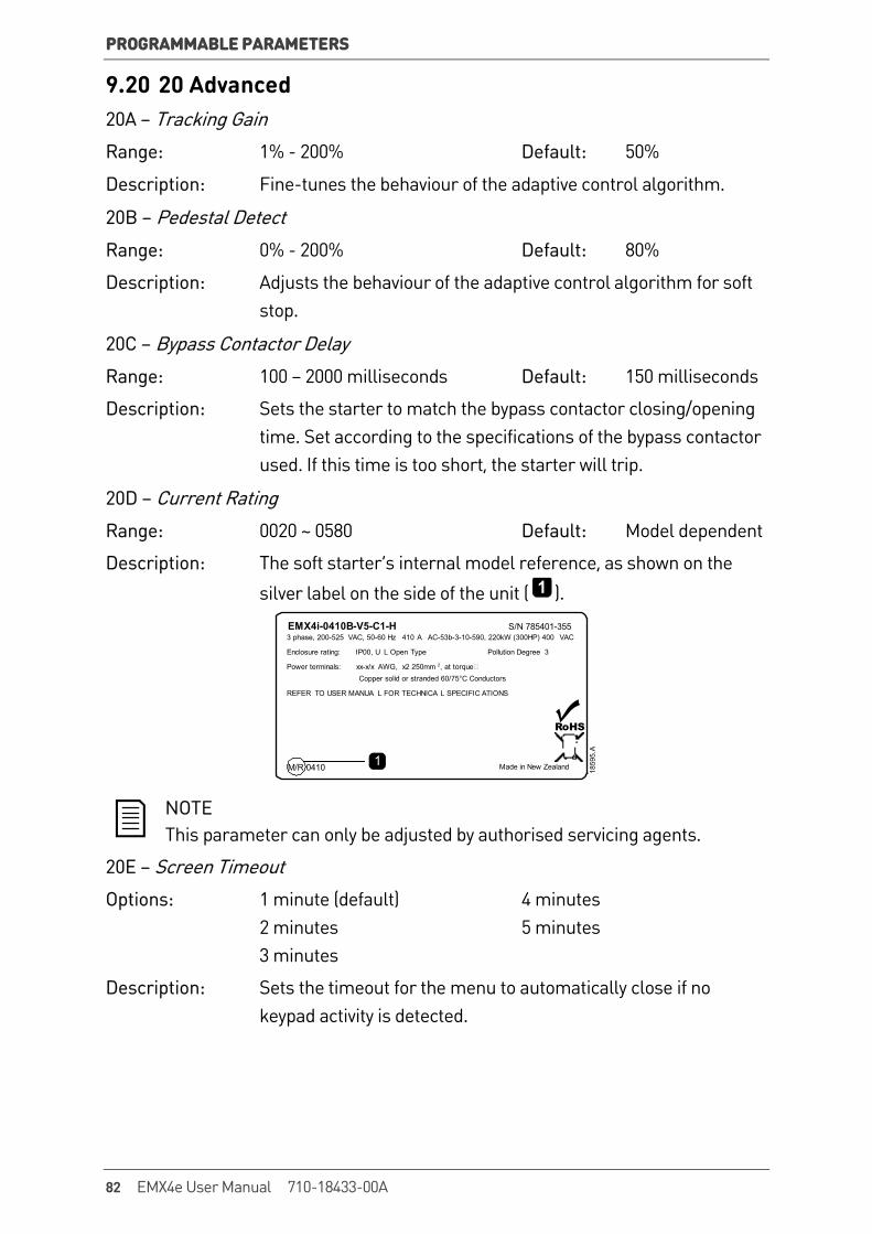
PROGRAMMABLE PARAMETERS
9.20 20 Advanced 20A – Tracking Gain
Range: 1% - 200% Default: 50%
Description: Fine-tunes the behaviour of the adaptive control algorithm.
20B – Pedestal Detect
Range: 0% - 200% Default: 80%
Description: Adjusts the behaviour of the adaptive control algorithm for soft stop.
20C – Bypass Contactor Delay
Range: 100 – 2000 milliseconds Default: 150 milliseconds
Description: Sets the starter to match the bypass contactor closing/opening time. Set according to the specifications of the bypass contactor used. If this time is too short, the starter will trip.
20D – Current Rating
Range: 0020 ~ 0580 Default: Model dependent
Description: The soft starter’s internal model reference, as shown on the
silver label on the side of the unit ( ).
3 phase, 200-525 VAC, 50-60 Hz 410 A AC-53b-3-10-590, 220kW (300HP) 400 VAC
Enclosure rating: IP00, U L Open Type Pollution Degree 3
Power terminals: xx-x/x AWG, x2 250mm 2, at torque Copper solid or stranded 60/75°C Conductors
REFER TO USER MANUA L FOR TECHNICA L SPECIFIC ATIONS
1859
5.A
1
EMX4i-0410B-V5-C1-H S/N 785401-355
M/R 0410 Made in New Zealand
RoHS
NOTE This parameter can only be adjusted by authorised servicing agents.
20E – Screen Timeout
Options: 1 minute (default) 4 minutes 2 minutes 5 minutes 3 minutes
Description: Sets the timeout for the menu to automatically close if no keypad activity is detected.
82 EMX4e User Manual 710-18433-00A
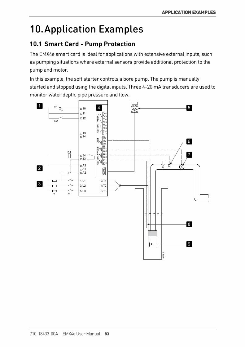
APPLICATION EXAMPLES
10. Application Examples 10.1 Smart Card - Pump Protection The EMX4e smart card is ideal for applications with extensive external inputs, such as pumping situations where external sensors provide additional protection to the pump and motor.
In this example, the soft starter controls a bore pump. The pump is manually started and stopped using the digital inputs. Three 4-20 mA transducers are used to monitor water depth, pipe pressure and flow.
10
11
12
A3A1A2
1/L1
3/L2
5/L3
2/T1
4/T2
6/T3
1314
3433
K1
K1F1
Start Stop Reset LCLRMT
MenuStoreExit
GraphLogs Tools
S1
S2
DIG
ITAL IN
PU
TS4/20m
A INP
UTS
RTD
C24C33C34C43
C13C14C23
C44
B14B13
B23B24B33B34
R2R1
R3
1
2
3
4
1865
4.A
6
7
8
9
5
710-18433-00A EMX4e User Manual 83
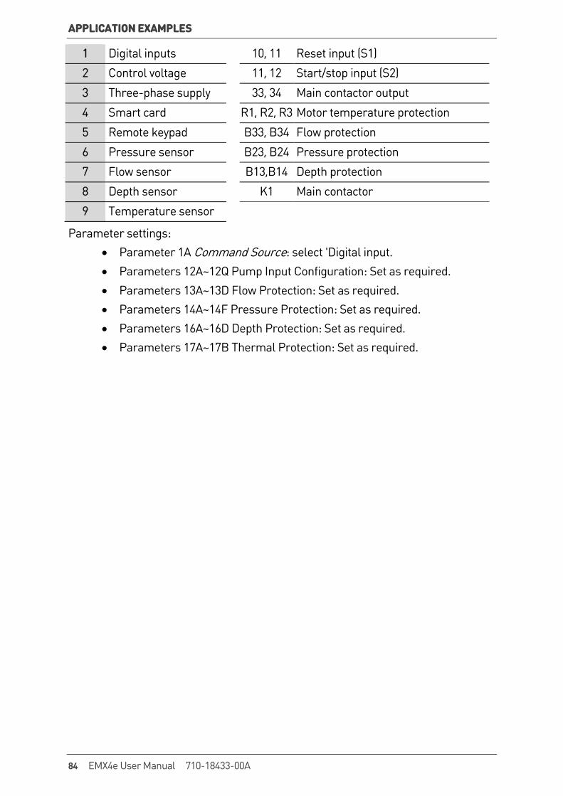
APPLICATION EXAMPLES
1 Digital inputs 10, 11 Reset input (S1)
2 Control voltage 11, 12 Start/stop input (S2)
3 Three-phase supply 33, 34 Main contactor output
4 Smart card R1, R2, R3 Motor temperature protection
5 Remote keypad B33, B34 Flow protection
6 Pressure sensor B23, B24 Pressure protection
7 Flow sensor B13,B14 Depth protection
8 Depth sensor K1 Main contactor
9 Temperature sensor
Parameter settings: • Parameter 1A Command Source: select 'Digital input. • Parameters 12A~12Q Pump Input Configuration: Set as required. • Parameters 13A~13D Flow Protection: Set as required. • Parameters 14A~14F Pressure Protection: Set as required. • Parameters 16A~16D Depth Protection: Set as required. • Parameters 17A~17B Thermal Protection: Set as required.
84 EMX4e User Manual 710-18433-00A
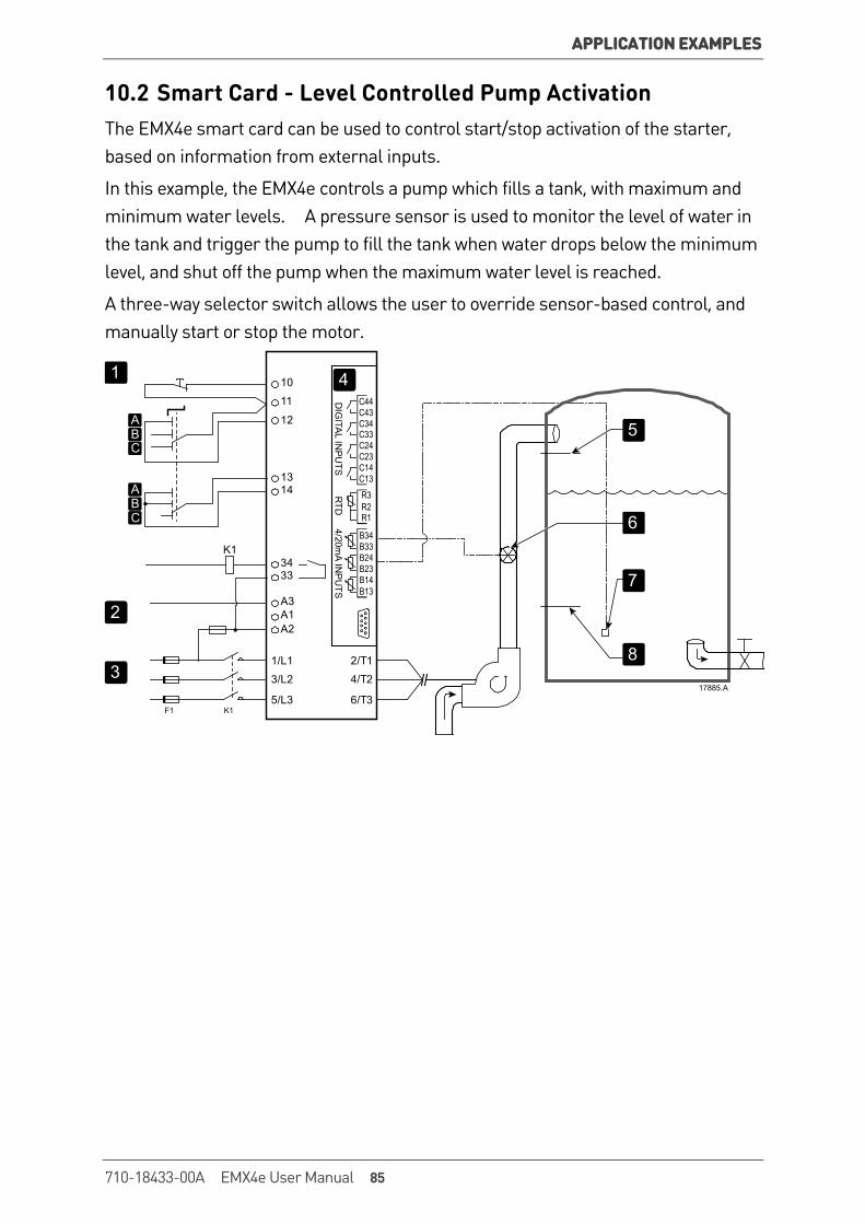
APPLICATION EXAMPLES
10.2 Smart Card - Level Controlled Pump Activation The EMX4e smart card can be used to control start/stop activation of the starter, based on information from external inputs.
In this example, the EMX4e controls a pump which fills a tank, with maximum and minimum water levels. A pressure sensor is used to monitor the level of water in the tank and trigger the pump to fill the tank when water drops below the minimum level, and shut off the pump when the maximum water level is reached.
A three-way selector switch allows the user to override sensor-based control, and manually start or stop the motor.
10
11
12
A3A1A2
1/L1
3/L2
5/L3
2/T1
4/T2
6/T3
1314
3433
K1
K1F1
DIG
ITAL IN
PU
TS4/20m
A INP
UTS
RTD
C24C33C34C43
C13C14C23
C44
B14B13
B23B24B33B34
R2R1
R3
1
ABC
ABC
2
3
4
17885.A
7
8
5
6
710-18433-00A EMX4e User Manual 85
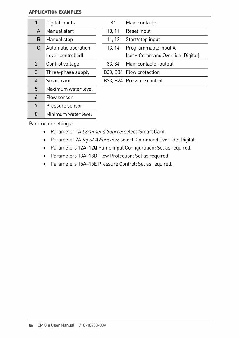
APPLICATION EXAMPLES
1 Digital inputs K1 Main contactor
A Manual start 10, 11 Reset input
B Manual stop 11, 12 Start/stop input
C Automatic operation (level-controlled)
13, 14 Programmable input A (set = Command Override: Digital)
2 Control voltage 33, 34 Main contactor output
3 Three-phase supply B33, B34 Flow protection
4 Smart card B23, B24 Pressure control
5 Maximum water level
6 Flow sensor
7 Pressure sensor
8 Minimum water level
Parameter settings: • Parameter 1A Command Source: select 'Smart Card'. • Parameter 7A Input A Function: select 'Command Override: Digital'. • Parameters 12A~12Q Pump Input Configuration: Set as required. • Parameters 13A~13D Flow Protection: Set as required. • Parameters 15A~15E Pressure Control: Set as required.
86 EMX4e User Manual 710-18433-00A
TROUBLESHOOTING
11. Troubleshooting 11.1 Protection Responses When a protection condition is detected, the EMX4e will write this to the event log and may also trip or issue a warning. The soft starter's response depends on the Protection Action setting (parameter group 6).
Some protection responses cannot be adjusted by the user. These trips are usually caused by external events (such as phase loss) or by a fault within the soft starter. These trips do not have associated parameters and cannot be set to Warn or Log.
If the EMX4e trips you will need to identify and clear the condition that triggered the trip, then reset the soft starter before restarting. To reset the starter, press the RESET button on the keypad or activate the Reset remote input.
If the EMX4e has issued a warning, the soft starter will reset itself once the cause of the warning has been resolved.
11.2 Trip Messages Display Possible cause/Suggested solution
Bypass overload This trip is not adjustable. Bypass overload protection protects the soft starter from severe operating overloads while running. The soft starter will trip if it detects overcurrent at 600% of the contactor rating. Related parameters: None
Current imbalance Current imbalance can be caused by problems with the motor, the environment or the installation, such as: • An imbalance in the incoming mains voltage • A problem with the motor windings • A light load on the motor • A phase loss on input terminals L1, L2 or L3 during Run
mode • An SCR that has failed open circuit. A failed SCR can only
be definitely diagnosed by replacing the SCR and checking the starter's performance.
Related parameters: 5A, 5B, 6A
710-18433-00A EMX4e User Manual 87

TROUBLESHOOTING
Display Possible cause/Suggested solution
Current Read Err Lx Where 'X' is 1, 2 or 3. Internal fault (PCB fault). The output from the CT circuit is not close enough to zero when the SCRs are turned off. Contact your local supplier for advice. Related parameters: None
EEPROM fail An error occurred loading data from the EEPROM to RAM when the keypad powered up. If the problem persists, contact your local distributor. Related parameters: None
Excess start time Excess start time trip can occur in the following conditions: • parameter 1B Motor Full Load Current is not appropriate for
the motor • parameter 2D Current Limit has been set too low • parameter 2B Start Ramp Time has been set greater than
the setting for 5G Excess Start Time setting parameter 2B Start Ramp Time is set too short for a high inertia load when using Adaptive Control Related parameters: 1B, 2B, 2D, 3B, 3D
Firing Fail Px Where 'X' is phase 1, 2 or 3. The SCR did not fire as expected. The SCR may be faulty or there may be an internal wiring fault. Related parameters: None
Flow Switch The smart card has detected zero flow on sensor 3 (B33, B34). Related parameters: 12G
Frequency This trip is not adjustable. The mains frequency has gone beyond the specified range. Check for other equipment in the area that could be affecting the mains supply, particularly variable speed drives and switch mode power supplies (SMPS). If the EMX4e is connected to a generator set supply, the generator may be too small or could have a speed regulation problem. Related parameters: 6I
88 EMX4e User Manual 710-18433-00A
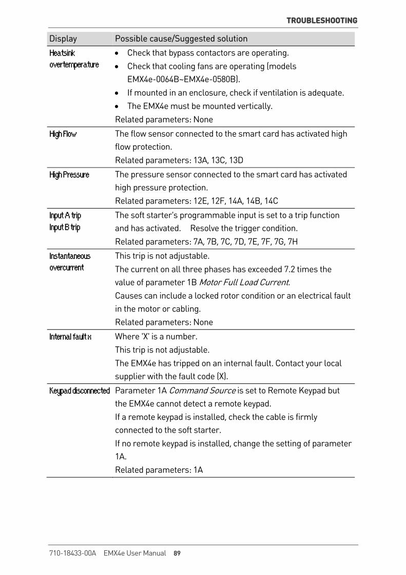
TROUBLESHOOTING
Display Possible cause/Suggested solution
Heatsink overtemperature
• Check that bypass contactors are operating. • Check that cooling fans are operating (models
EMX4e-0064B~EMX4e-0580B). • If mounted in an enclosure, check if ventilation is adequate. • The EMX4e must be mounted vertically. Related parameters: None
High Flow The flow sensor connected to the smart card has activated high flow protection. Related parameters: 13A, 13C, 13D
High Pressure The pressure sensor connected to the smart card has activated high pressure protection. Related parameters: 12E, 12F, 14A, 14B, 14C
Input A trip Input B trip
The soft starter's programmable input is set to a trip function and has activated. Resolve the trigger condition. Related parameters: 7A, 7B, 7C, 7D, 7E, 7F, 7G, 7H
Instantaneous overcurrent
This trip is not adjustable. The current on all three phases has exceeded 7.2 times the value of parameter 1B Motor Full Load Current. Causes can include a locked rotor condition or an electrical fault in the motor or cabling. Related parameters: None
Internal fault x Where 'X' is a number. This trip is not adjustable. The EMX4e has tripped on an internal fault. Contact your local supplier with the fault code (X).
Keypad disconnected Parameter 1A Command Source is set to Remote Keypad but the EMX4e cannot detect a remote keypad. If a remote keypad is installed, check the cable is firmly connected to the soft starter. If no remote keypad is installed, change the setting of parameter 1A. Related parameters: 1A
710-18433-00A EMX4e User Manual 89

TROUBLESHOOTING
Display Possible cause/Suggested solution
L1 phase loss L2 phase loss L3 phase loss
This trip is not adjustable. During pre-start checks the starter has detected a phase loss as indicated. In run state, the starter has detected that the current on the affected phase has dropped below 2% of the programmed motor FLC for more than 1 second, indicating that either the incoming phase or connection to the motor has been lost. Check the supply and the input and output connections at the starter and at the motor end. Related parameters: None
L1-T1 shorted L2-T2 shorted L3-T3 shorted
During pre-start checks the starter has detected a shorted SCR or a short within the bypass contactor as indicated. Consider using PowerThrough to allow operation until the starter can be repaired. Related parameters: 6L
Low Control Volts The EMX4e has detected a drop in the internal control voltage. • Check the external control supply (A1, A2, A3) and reset the
starter. If the external control supply is stable: • the 24 V supply on the main control PCB may be faulty; or • the bypass driver PCB may be faulty. Contact your local
supplier for advice. This protection is not active in Ready state. Related parameters: None
Low Flow The flow sensor connected to the smart card has activated low flow protection. Related parameters: 13B, 13C, 13D
Low Pressure The pressure sensor connected to the smart card has activated low pressure protection. Related parameters: 12E, 12F, 14D, 14E, 14F
Low Water The depth sensor connected to the smart card has activated depth protection. Related parameters: 12P, 12Q, 16A, 16B, 16C
90 EMX4e User Manual 710-18433-00A
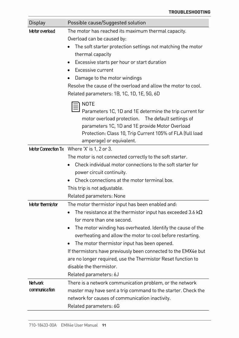
TROUBLESHOOTING
Display Possible cause/Suggested solution
Motor overload The motor has reached its maximum thermal capacity. Overload can be caused by: • The soft starter protection settings not matching the motor
thermal capacity • Excessive starts per hour or start duration • Excessive current • Damage to the motor windings Resolve the cause of the overload and allow the motor to cool. Related parameters: 1B, 1C, 1D, 1E, 5G, 6D
NOTE Parameters 1C, 1D and 1E determine the trip current for motor overload protection. The default settings of parameters 1C, 1D and 1E provide Motor Overload Protection: Class 10, Trip Current 105% of FLA (full load amperage) or equivalent.
Motor Connection Tx Where 'X' is 1, 2 or 3. The motor is not connected correctly to the soft starter. • Check individual motor connections to the soft starter for
power circuit continuity. • Check connections at the motor terminal box. This trip is not adjustable. Related parameters: None
Motor thermistor The motor thermistor input has been enabled and: • The resistance at the thermistor input has exceeded 3.6 kΩ
for more than one second. • The motor winding has overheated. Identify the cause of the
overheating and allow the motor to cool before restarting. • The motor thermistor input has been opened. If thermistors have previously been connected to the EMX4e but are no longer required, use the Thermistor Reset function to disable the thermistor. Related parameters: 6J
Network communication
There is a network communication problem, or the network master may have sent a trip command to the starter. Check the network for causes of communication inactivity. Related parameters: 6G
710-18433-00A EMX4e User Manual 91
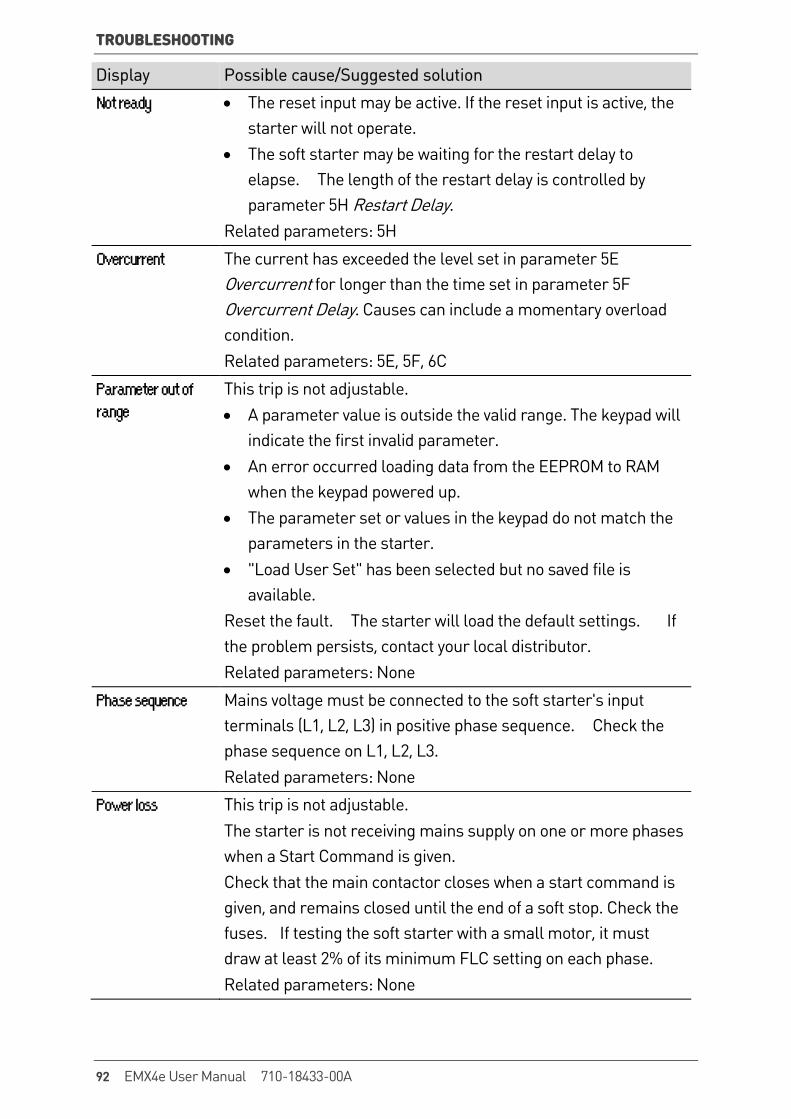
TROUBLESHOOTING
Display Possible cause/Suggested solution
Not ready • The reset input may be active. If the reset input is active, the starter will not operate.
• The soft starter may be waiting for the restart delay to elapse. The length of the restart delay is controlled by parameter 5H Restart Delay.
Related parameters: 5H
Overcurrent The current has exceeded the level set in parameter 5E Overcurrent for longer than the time set in parameter 5F Overcurrent Delay. Causes can include a momentary overload condition. Related parameters: 5E, 5F, 6C
Parameter out of range
This trip is not adjustable. • A parameter value is outside the valid range. The keypad will
indicate the first invalid parameter. • An error occurred loading data from the EEPROM to RAM
when the keypad powered up. • The parameter set or values in the keypad do not match the
parameters in the starter. • "Load User Set" has been selected but no saved file is
available. Reset the fault. The starter will load the default settings. If the problem persists, contact your local distributor. Related parameters: None
Phase sequence Mains voltage must be connected to the soft starter's input terminals (L1, L2, L3) in positive phase sequence. Check the phase sequence on L1, L2, L3. Related parameters: None
Power loss This trip is not adjustable. The starter is not receiving mains supply on one or more phases when a Start Command is given. Check that the main contactor closes when a start command is given, and remains closed until the end of a soft stop. Check the fuses. If testing the soft starter with a small motor, it must draw at least 2% of its minimum FLC setting on each phase. Related parameters: None
92 EMX4e User Manual 710-18433-00A
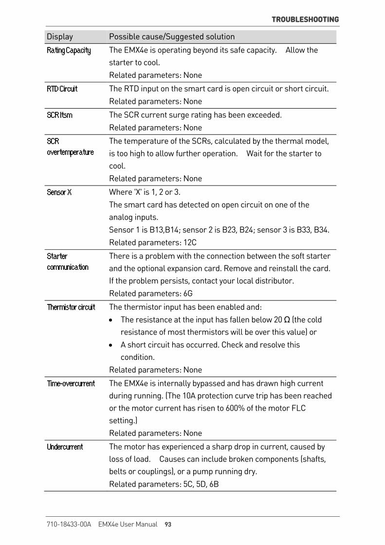
TROUBLESHOOTING
Display Possible cause/Suggested solution
Rating Capacity The EMX4e is operating beyond its safe capacity. Allow the starter to cool. Related parameters: None
RTD Circuit The RTD input on the smart card is open circuit or short circuit. Related parameters: None
SCR Itsm The SCR current surge rating has been exceeded. Related parameters: None
SCR overtemperature
The temperature of the SCRs, calculated by the thermal model, is too high to allow further operation. Wait for the starter to cool. Related parameters: None
Sensor X Where 'X' is 1, 2 or 3. The smart card has detected on open circuit on one of the analog inputs. Sensor 1 is B13,B14; sensor 2 is B23, B24; sensor 3 is B33, B34. Related parameters: 12C
Starter communication
There is a problem with the connection between the soft starter and the optional expansion card. Remove and reinstall the card. If the problem persists, contact your local distributor. Related parameters: 6G
Thermistor circuit The thermistor input has been enabled and: • The resistance at the input has fallen below 20 Ω (the cold
resistance of most thermistors will be over this value) or • A short circuit has occurred. Check and resolve this
condition. Related parameters: None
Time-overcurrent The EMX4e is internally bypassed and has drawn high current during running. (The 10A protection curve trip has been reached or the motor current has risen to 600% of the motor FLC setting.) Related parameters: None
Undercurrent The motor has experienced a sharp drop in current, caused by loss of load. Causes can include broken components (shafts, belts or couplings), or a pump running dry. Related parameters: 5C, 5D, 6B
710-18433-00A EMX4e User Manual 93
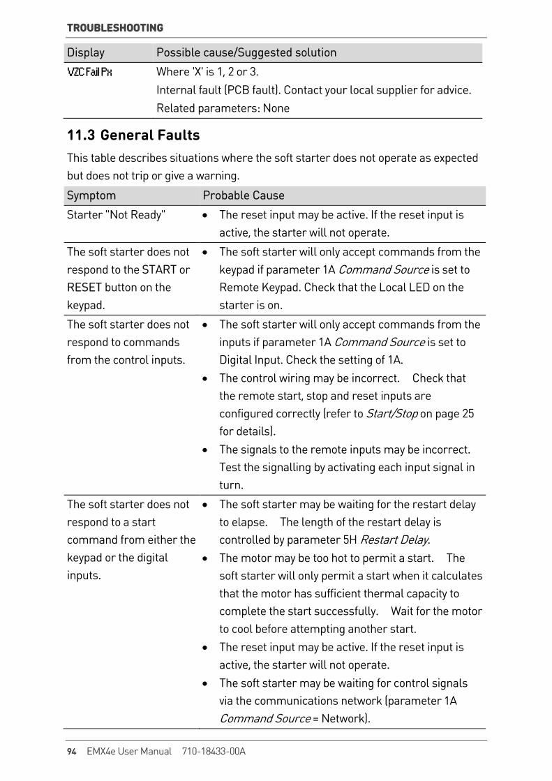
TROUBLESHOOTING
Display Possible cause/Suggested solution
VZC Fail Px Where 'X' is 1, 2 or 3. Internal fault (PCB fault). Contact your local supplier for advice. Related parameters: None
11.3 General Faults This table describes situations where the soft starter does not operate as expected but does not trip or give a warning.
Symptom Probable Cause
Starter "Not Ready" • The reset input may be active. If the reset input is active, the starter will not operate.
The soft starter does not respond to the START or RESET button on the keypad.
• The soft starter will only accept commands from the keypad if parameter 1A Command Source is set to Remote Keypad. Check that the Local LED on the starter is on.
The soft starter does not respond to commands from the control inputs.
• The soft starter will only accept commands from the inputs if parameter 1A Command Source is set to Digital Input. Check the setting of 1A.
• The control wiring may be incorrect. Check that the remote start, stop and reset inputs are configured correctly (refer to Start/Stop on page 25 for details).
• The signals to the remote inputs may be incorrect. Test the signalling by activating each input signal in turn.
The soft starter does not respond to a start command from either the keypad or the digital inputs.
• The soft starter may be waiting for the restart delay to elapse. The length of the restart delay is controlled by parameter 5H Restart Delay.
• The motor may be too hot to permit a start. The soft starter will only permit a start when it calculates that the motor has sufficient thermal capacity to complete the start successfully. Wait for the motor to cool before attempting another start.
• The reset input may be active. If the reset input is active, the starter will not operate.
• The soft starter may be waiting for control signals via the communications network (parameter 1A Command Source = Network).
94 EMX4e User Manual 710-18433-00A

TROUBLESHOOTING
Symptom Probable Cause
Remote keypad shows message "awaiting data"
The keypad is not receiving data from the control PCB. Check the cable connection.
The soft starter does not control the motor correctly during starting.
• Start performance may be unstable when using a low Motor Full Load Current setting (parameter 1B).
• Power factor correction (PFC) capacitors must be installed on the supply side of the soft starter and must be disconnected during starting and stopping. To use the EMX4e to control power factor correction, connect the PFC contactor to a programmable relay set to Run.
• High levels of harmonics on the mains supply can affect soft starter performance. If variable speed drives are installed nearby, check they are properly grounded and filtered.
Motor does not reach full speed.
• If the start current is too low, the motor will not produce enough torque to accelerate to full speed. The soft starter may trip on excess start time.
NOTE Make sure the motor starting parameters are appropriate for the application and that you are using the intended motor starting profile. If a programmable input is set to Motor Set Select, check that the corresponding input is in the expected state.
• The load may be jammed. Check the load for severe overloading or a locked rotor situation.
Soft stop ends too quickly. • The soft stop settings may not be appropriate for the motor and load. Review the soft stop settings.
• If the motor is very lightly loaded, soft stop will have limited effect.
After selecting Adaptive Control the motor used an ordinary start and/or the second start was different to the first.
• The first Adaptive Control start is actually 'Constant Current' so that the starter can learn from the motor characteristics. Subsequent starts use Adaptive Control.
710-18433-00A EMX4e User Manual 95
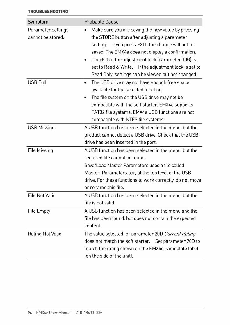
TROUBLESHOOTING
Symptom Probable Cause
Parameter settings cannot be stored.
• Make sure you are saving the new value by pressing the STORE button after adjusting a parameter setting. If you press EXIT, the change will not be saved. The EMX4e does not display a confirmation.
• Check that the adjustment lock (parameter 10G) is set to Read & Write. If the adjustment lock is set to Read Only, settings can be viewed but not changed.
USB Full • The USB drive may not have enough free space available for the selected function.
• The file system on the USB drive may not be compatible with the soft starter. EMX4e supports FAT32 file systems. EMX4e USB functions are not compatible with NTFS file systems.
USB Missing A USB function has been selected in the menu, but the product cannot detect a USB drive. Check that the USB drive has been inserted in the port.
File Missing A USB function has been selected in the menu, but the required file cannot be found. Save/Load Master Parameters uses a file called Master_Parameters.par, at the top level of the USB drive. For these functions to work correctly, do not move or rename this file.
File Not Valid A USB function has been selected in the menu, but the file is not valid.
File Empty A USB function has been selected in the menu and the file has been found, but does not contain the expected content.
Rating Not Valid The value selected for parameter 20D Current Rating does not match the soft starter. Set parameter 20D to match the rating shown on the EMX4e nameplate label (on the side of the unit).
96 EMX4e User Manual 710-18433-00A
New Zealand123 Wrights Road, PO Box 80208, Christchurch 8440, New ZealandT +64 3 338 8280 F +64 3 338 8104
China203-1 JH Plaza, 2008 Huqingping Road, Shanghai 201702, ChinaT +86 21 5877 5178 F +86 21 5877 6378
GermanyAm Mergelberg 2, 48324 Sendenhorst, GermanyT +49 2526 93880 140 F +49 2526 93880 100
Middle East10th Floor, Jumeirah Lakes Towers, Dubai, UAET +971 4279 8349 F +971 4279 8399
North America2528 Lovi Road, Building 2-2A, Freedom, PA 15042, USAT 855 928 2666 (855 AUCOM NA), +1 724 987 4952 F +1 724 510 3005 http://my.aucom.com
For more information and your local contact visit www.aucom.com
È710
-184
33-0
0A9Ë
Í710-18433-00A