user guide - migatronic · user guide robot control ... product code: 98 (0062h) ... the anybus...
TRANSCRIPT
USER GUIDE
ROBOT CONTROL INTERFACE - RCI2
50115001 C Valid from 2016 week 50
2 3
Specifications .............................................................................................. 3 - 4
How it works .................................................................................................... 5
Connection to a robot and welding machine ................................................ 6
How to connect the installation ................................................................ 7 - 8
How to do the first configuration and setup ................................................ 9
Jumper settings ............................................................................................. 10
Fieldbus serial communication setup .......................................................... 11
Status menu ............................................................................................ 12 - 14
Setup menu ............................................................................................. 15 - 31
Robot / PLC setup ........................................................................................... 32
Analog Configuration file - PI ................................................................ 33 - 38
Fieldbus Configuration file - PI and PI PLASMA ................................... 39 - 46
Fieldbus Configuration file - PI and PI PLASMA - Std. Motoman ....... 47 - 49
Analog Configuration file - Sigma Galaxy ............................................ 50 - 57
Fieldbus Configuration file - Sigma Galaxy - Standard ....................... 58 - 60
Fieldbus Configuration file - Sigma Galaxy - Standard Motoman ...... 61 - 64
Detailed Interface layout .............................................................................. 65
Software upgrade .......................................................................................... 66
Troubleshooting ............................................................................................. 67
Error List .................................................................................................. 68 - 70
ANYBUS - Error List ................................................................................. 71 - 75
Electric Diagram ............................................................................................. 76
SIGMA Robot interface basic setup .............................................................. 77
Spare parts list ............................................................................................... 78
Table of contents

2 3
Specifications
SUPPORTED POWER SOURCES
Migatronic power sources: SIGMA GALAXY with control unit 76113597, PI 350/500 and PI PLASMA
ANALOG PART OF INTERFACE
ANALOG INPUTSGalvanic isolated differential inputs: 3
Common mode range: ± 20 VDC
Max differential voltage: 10 VDC
Differential Input impedance: 100K Ohm
Sampling frequency: 100 Hz
Max. pulse frequency (square wave): 10 Hz
Digital resolution: 10 Bit
Error: ± 2 % of reading ± 2 digits(20mV)
ANALOG OUTPUTSGalvanic isolated differential outputs: 2
Maximum load: 2K Ohm
Output voltage: 0-10 V
Digital resolution: 12 Bit
Sampling frequency: 97 Hz
Error: ± 2 % of reading ± 5 digits(50mV)
Remarks: cannot be used for certification of the welding process
DIGITAL INPUTSGalvanic isolated inputs: 16
HIGH level (H): 10-26 VDC
LOW level (L): 0-3 VDC
Input impedance: 5K Ohm
Response time to input changes: 100 ms
DIGITAL OUTPUTSGalvanic isolated outputs: 16
LOW level: 0 V
HIGH level: +20V from internal supply (JMP2 1-2) or +24V from external supply (JPM2 2-3)
Max load: 50 mA
Response time: 100 ms
GENERAL DATAOperating temperature: -10 to 40°C (14 to 104°F)
4 5
Specifications
FIELDBUS PART OF INTERFACE
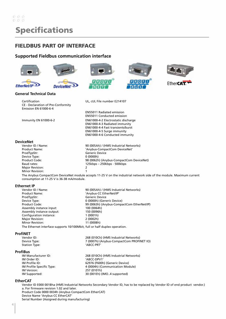
Supported Fieldbus communication interface
General Technical Data
Certification UL, cUL File number E214107 CE - Declaration of Pre-Conformity Emission EN 61000-6-4 EN55011 Radiated emission EN55011 Conducted emission Immunity EN 61000-6-2 EN61000-4-2 Electrostatic discharge EN61000-4-3 Radiated immunity EN61000-4-4 Fast transients/burst EN61000-4-5 Surge immunity EN61000-4-6 Conducted immunity
DeviceNet Vendor ID / Name: 90 (005Ah) / (HMS Industrial Networks) Product Name: ‘Anybus-CompactCom DeviceNet’ ProdTypStr: Generic Device Device Type: 0 (0000h) Product Code: 98 (0062h) (Anybus-CompactCom DeviceNet) Baud rates: 125kbps – 250kbps - 500kbps Major Revision: 2 Minor Revision: 1
The Anybus CompactCom DeviceNet module accepts 11-25 V on the industrial network side of the module. Maximum current consumption at 11-25 V is 36-38 mA/module.
Ethernet IP Vendor ID / Name: 90 (005Ah) / (HMS Industrial Networks) Product Name: ‘Anybus-CC EtherNet/IP’ ProdTypStr: Generic Device Device Type: 0 (0000h) (Generic Device) Product Code: 99 (0063h) (Anybus-CompactCom EtherNet/IP) Assembly instance input: 100 (0064h) Assembly instance output: 150 (0096h) Configuration instance: 1 (0001h) Major Revision: 2 (0002h) Minor Revision: 11 (000Bh)
The Ethernet interface supports 10/100Mbit, full or half duplex operation.
ProfiNET Vendor ID: 268 (010Ch) (HMS Industrial Networks) Device Type: 7 (0007h) (Anybus-CompactCom PROFINET IO) Station Type: ‘ABCC-PRT’
ProfiBus IM Manufacturer ID: 268 (010Ch) (HMS Industrial Networks) IM Order ID: ‘ABCC-DPV1’ IM Profile ID: 62976 (F600h) (Generic Device) IM Profile Specific Type: 4 (0004h) (Communication Module) IM Version: 257 (0101h) IM Supported: 30 (001Eh) (IMO..4 supported)
EtherCAT Vendor ID E000 001Bha (HMS Industrial Networks Secondary Vendor ID, has to be replaced by Vendor ID of end product vendor.) a. For firmware revision 1.02 and later. Product Code 0000 0034h (Anybus CompactCom EtherCAT) Device Name ‘Anybus-CC EtherCAT’ Serial Number (Assigned during manufacturing)
4 5
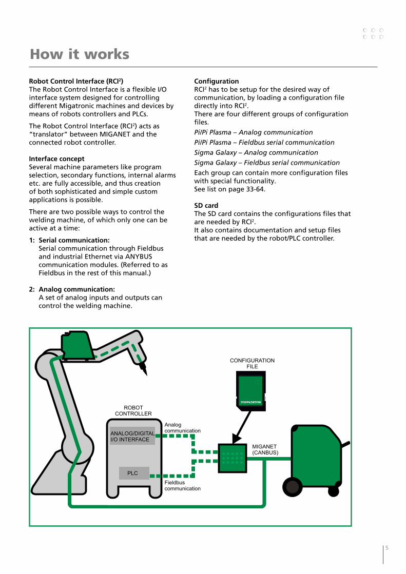
Robot Control Interface (RCI2)The Robot Control Interface is a flexible I/O interface system designed for controlling different Migatronic machines and devices by means of robots controllers and PLCs.
The Robot Control Interface (RCI2) acts as “translator” between MIGANET and the connected robot controller.
Interface conceptSeveral machine parameters like program selection, secondary functions, internal alarms etc. are fully accessible, and thus creation of both sophisticated and simple custom applications is possible.
There are two possible ways to control the welding machine, of which only one can be active at a time:
1: Serial communication: Serial communication through Fieldbus
and industrial Ethernet via ANYBUS communication modules. (Referred to as Fieldbus in the rest of this manual.)
2: Analog communication: A set of analog inputs and outputs can
control the welding machine.
ConfigurationRCI2 has to be setup for the desired way of communication, by loading a configuration file directly into RCI2.There are four different groups of configuration files.
Pi/Pi Plasma – Analog communication
Pi/Pi Plasma – Fieldbus serial communication
Sigma Galaxy – Analog communication
Sigma Galaxy – Fieldbus serial communication
Each group can contain more configuration files with special functionality.See list on page 33-64.
SD cardThe SD card contains the configurations files that are needed by RCI2.It also contains documentation and setup files that are needed by the robot/PLC controller.
How it works
PLC
Fieldbuscommunication
Analogcommunication
MIGANET(CANBUS)
ANALOG/DIGITALI/O INTERFACE
ROBOTCONTROLLER
CONFIGURATIONFILE

6 7
Analog connectionto robot
CANBUS connectionto welding machine
Fieldbus connectionto robot
Connection to robot and welding machine
Fieldbus communication
One of the following Anybus modules is installed when RCI2 is intended for serial communication.
ETHERNET/IP DEVICENET PROFINET PROFIBUS EtherCAT
Analog communication
The analog communication is accessible through the 37 pin military plug.
The configuration file is defining the function of each pin.
Setup for analog communication. See page 9Analog connection
to robot
RCI2

6 7
How to connect the installation
Main components:1. Interface - RCI2 I/O2. Welding inverter - MIG /TIG/Plasma TIG3. Wire feed unit - RWF2/CWF4. Remote2 control5. CAN connector box6. Ext. cooler - option for Plasma TIG
Analogcommunication
CONTROLLER
ANALOG/DIGITALI/O INTERFACE
f
1ANALOG/DIGITALI/O INTERFACE
ROBOT / PLCCONTROLLER
1
3 windingsthrough core17440005
RWF²
SIGMA GALAXY
REMOTE²
3
MIGANET(CANBUS)
RCI²
Fieldbuscommunication
b
1
2
4
g
b
c
e
max. 3 m
Cables and fittings: a. Signal cable for robot controller fieldbus or analog b. CAN communication cable for welding inverter c. Interconnection, water hose, gas and 2xwelding cable and CAN d. Highly flexible interconnection for robot e. Earth connection f. Welding torch g. Welding return cable h. Interconnection, water hose, gas and welding cable
Welding process Distance to work piece( + + )
Total cable length in welding circuit( + + + )
Total length of CAN cable( + + )
MIG – IAC and pulse 10 m 20 m 30 m
MIG – non pulse 30 m 60 m 30 m
TIG 10 m 20 m 30 m
MIG installation
1
e
3 windingsthrough core17440005
g
PI & PLASMA TIG
CONNECTIONBOX
b
RCI²
Analogcommunication
REMOTE²
ROBOT / PLCCONTROLLER
b
CWF²
Fieldbuscommunication
2
b
4
b
a
a
CONTROLLER
ANALOG/DIGITALI/O INTERFACEANALOG/DIGITALI/O INTERFACE
f
d
3
h
Note:Keep distanceof 5 cm
6
EXT. COOLER
max. 3 m
TIG installation
fc g dc f cbhh
8 9
How to connect the installation
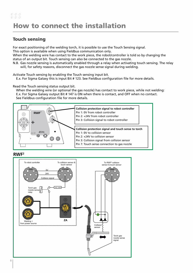
Touch sensing
For exact positioning of the welding torch, it is possible to use the Touch Sensing signal.This option is available when using Fieldbus communication only.When the welding wire has contact to the work piece, the robot/controller is told so by changing the status of an output bit. Touch sensing can also be connected to the gas nozzle.N.B. Gas nozzle sensing is automatically enabled through a relay when activating touch sensing. The relay
will, for safety reasons, disconnect the gas nozzle sense signal during welding.
Activate Touch sensing by enabling the Touch sensing input bit. E.x. For Sigma Galaxy this is input Bit # 123. See Fieldbus configuration file for more details.
Read the Touch sensing status output bit. When the welding wire (or optional the gas nozzle) has contact to work piece, while not welding: E.x. For Sigma Galaxy output Bit # 147 is ON when there is contact, and OFF when no contact. See Fieldbus configuration file for more details.
AIR Clean
Max.8 bar
Collision protection signal to robot controllerPin 1: 0V from robot controllerPin 2: +24V from robot controllerPin 3: Collision signal to robot controller
Collision protection signal and touch sense to torchPin 1: 0V to collision sensorPin 2: +24V to collision sensorPin 3: Collision signal from collision sensorPin 7: Touch sense connection to gas nozzle
Male1
2
3
Female1
2
3
7
To robot controller To collision sensor &touch sensor
Collision signal
24V
0V
1K 50WΩTorch gasnozzle senserelay
ZAWelding +from power source
Male1
2
3
7
To RWF² collisionsensor & touch sensor
Collisionsensor
Torch gasnozzle sensesignal
RWF2
8 9
How to do the first configuration and setup
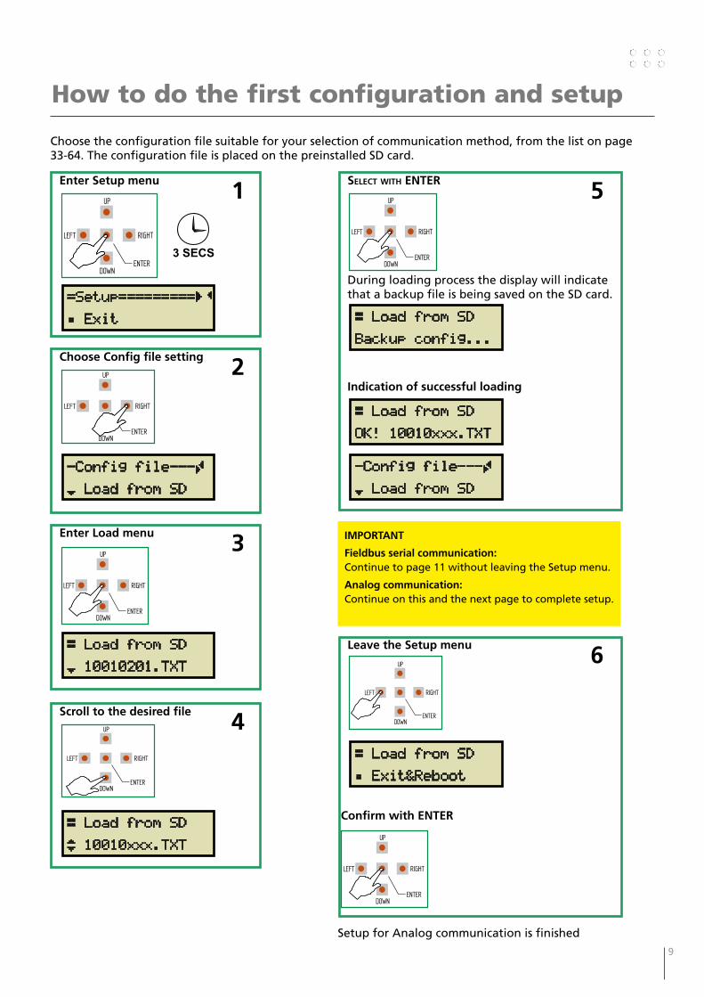
Choose the configuration file suitable for your selection of communication method, from the list on page 33-64. The configuration file is placed on the preinstalled SD card.
Enter Setup menu 1
=Setup=========ÇÄ
Á Exit
RIGHT
DOWNENTER
LEFT
UP
3 SECS
Choose Config file setting 2
RIGHT
DOWNENTER
LEFT
UP
-Config file---Ã
¾ Load from SD
Enter Load menu 3
RIGHT
DOWNENTER
LEFT
UP
Æ Load from SD
¾ 10010201.TXT
Scroll to the desired file 4
Æ Load from SD
¿ 10010xxx.TXT
RIGHT
DOWNENTER
LEFT
UP
Select With eNteR 5
During loading process the display will indicate that a backup file is being saved on the SD card.
Indication of successful loading
RIGHT
DOWNENTER
LEFT
UP
Æ Load from SD
Backup config...
Æ Load from SD
OK! 10010xxx.TXT
-Config file---Ã
¾ Load from SD
IMPORTANT
Fieldbus serial communication:Continue to page 11 without leaving the Setup menu.
Analog communication:Continue on this and the next page to complete setup.
Leave the Setup menu 6
Confirm with ENTER
RIGHT
DOWNENTER
LEFT
UP
Æ Load from SD
Á Exit&Reboot
RIGHT
DOWNENTER
LEFT
UP
Setup for Analog communication is finished
10 11
Jumper settings
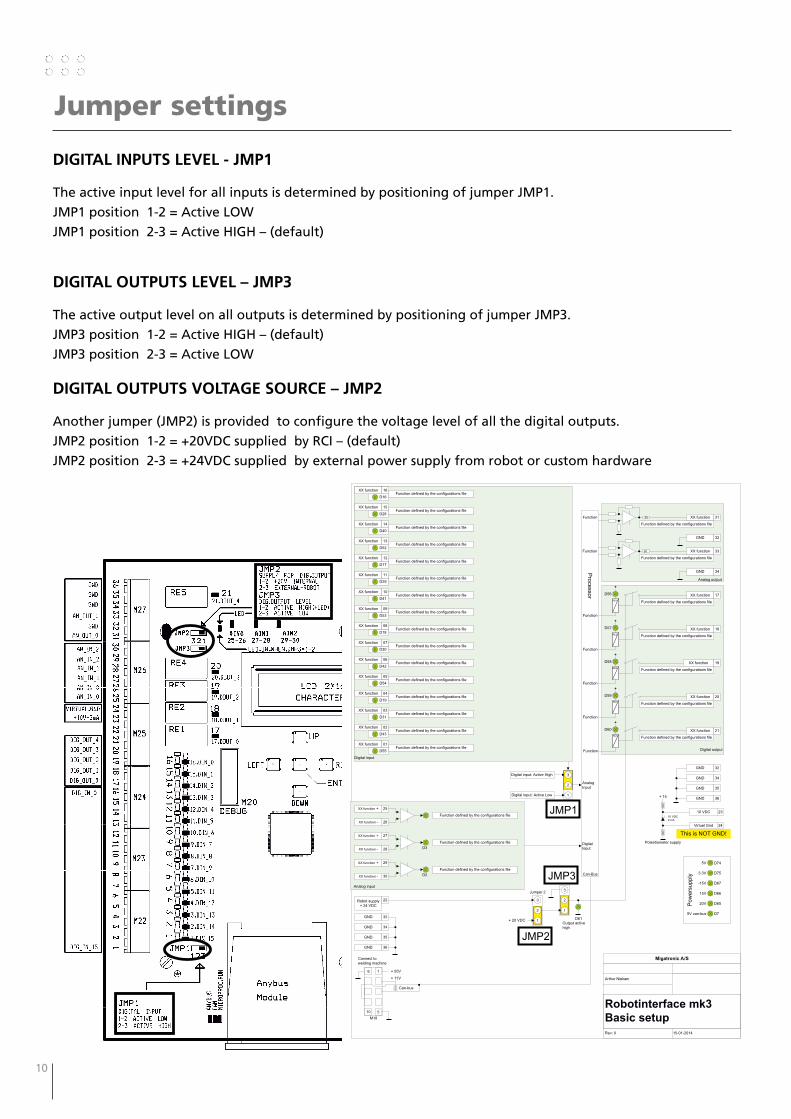
DiGitAl iNPUtS leVel - JMP1
The active input level for all inputs is determined by positioning of jumper JMP1.
JMP1 position 1-2 = Active LOW
JMP1 position 2-3 = Active HIGH – (default)
DiGitAl OUtPUtS leVel – JMP3
The active output level on all outputs is determined by positioning of jumper JMP3.
JMP3 position 1-2 = Active HIGH – (default)
JMP3 position 2-3 = Active LOW
DiGitAl OUtPUtS VOltAGe SOURce – JMP2
Another jumper (JMP2) is provided to configure the voltage level of all the digital outputs.
JMP2 position 1-2 = +20VDC supplied by RCI – (default)
JMP2 position 2-3 = +24VDC supplied by external power supply from robot or custom hardware
Migatronic A/S
Arthur Nielsen
Rev: 0 15-01-2014
Robotinterface mk3
Basic setup
Pro
cessor
15V
20V
3.3V
-15V
5V
Pow
ers
upply
XX function 10
D41
XX function 09
D53
XX function 08
D18
XX function 07
D30
D42
XX function 06
XX function 03
XX function 11
XX function 16
XX function 13
XX function 15
XX function 01
D31
D29
D16
D52
D28
Digital input
Digital
Input
2
1
3
Jumper 1
Digital input: Active High
Digital input: Active Low
Analog
Input
Robot supply
+ 24 VDC
22
2
1
3
Jumper 2
2
1
3
Jumper 3
GND 32
GND 34
D61Output active
high
+
+
+
+
XX function 17
XX function 18
XX function 19
XX function 20
RE1
RE2
RE3
RE4
D56
D57
D58
D59
GND 32
GND 34
GND 32
GND 34
XX function 33
XX function 3150
50
D74
D75
D67
D66
D65
D7
D55
+ 20 VDC
Analog output
Digital output
1
5
6
10
M18
+ 55V
+ 11V
Can-Bus
Connect to
welding machine
Can-bus
GND 35
GND 36
5V can-bus
GND 35
GND 36
Function defined by the configurations file
Function defined by the configurations file
Function defined by the configurations file
Function defined by the configurations file
Function defined by the configurations file
Function defined by the configurations file
Function defined by the configurations file
Function defined by the configurations file
Function defined by the configurations file
Function defined by the configurations file
Function defined by the configurations file
XX function 02
D43Function defined by the configurations file
XX function 05
D54Function defined by the configurations file
XX function 04
D19Function defined by the configurations file
XX function 12
D17Function defined by the configurations file
XX function 14
D40Function defined by the configurations file
D1
25XX function +
26XX function -
Analog input
D3
27XX function +
28XX function -
D2
29XX function +
30XX function -
Function defined by the configurations file
Function defined by the configurations file
Function defined by the configurations file
Function
Function
Function
Function
Function
Function
Function defined by the configurations file
Function defined by the configurations file
+
XX function 21
RE5
D60
Function defined by the configurations file
Function defined by the configurations file
Function defined by the configurations file
Function defined by the configurations file
Function defined by the configurations file
Function
+ 15
20
020
0
10 VDC
2 mA
Potentiometer supply
This is NOT GND!
10 VDC 23
Virtuel Gnd 24
JMP1
JMP3
JMP2
10 11
Fieldbus serial communication setup
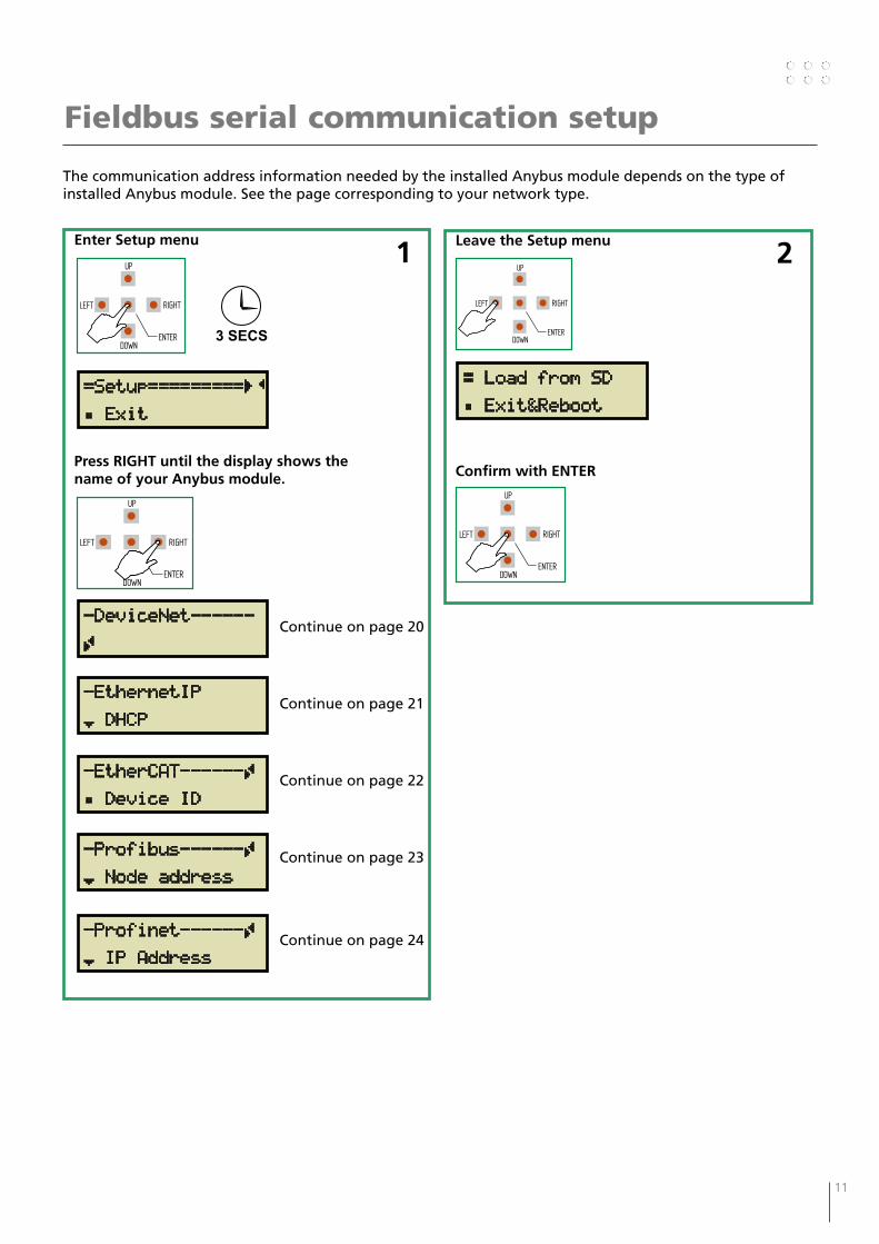
The communication address information needed by the installed Anybus module depends on the type of installed Anybus module. See the page corresponding to your network type.
Enter Setup menu 1
Press RIGHT until the display shows the name of your Anybus module.
Continue on page 20
Continue on page 21
Continue on page 22
Continue on page 23
Continue on page 24
RIGHT
DOWNENTER
LEFT
UP
-DeviceNet------
Ã
-EthernetIP
¾ DHCP
-Profibus------Ã
¾ Node address
-Profinet------Ã
¾ IP Address
Leave the Setup menu 2
Confirm with ENTER
RIGHT
DOWNENTER
LEFT
UP
Æ Load from SD
Á Exit&Reboot
RIGHT
DOWNENTER
LEFT
UP
=Setup=========ÇÄ
Á Exit
3 SECS
RIGHT
DOWNENTER
LEFT
UP
-EtherCAT------Ã
Á Device ID
12 13
Status menu
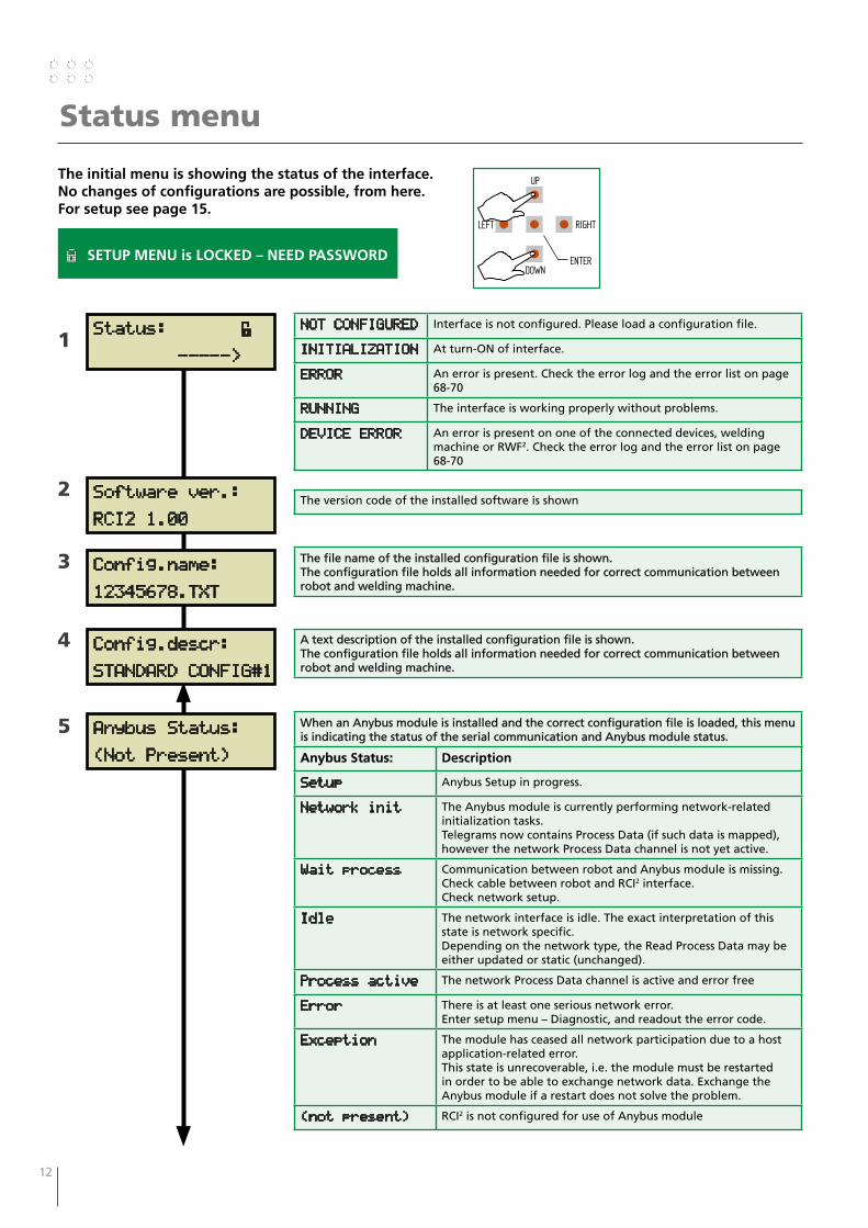
The initial menu is showing the status of the interface. No changes of configurations are possible, from here. For setup see page 15.
RIGHT
DOWNENTER
LEFT
UP
1
2
3
4
5
Status: É
----->
Software ver.:
RCI2 1.00
Config.name:
12345678.TXT
Config.descr:
STANDARD CONFIG#1
Anybus Status:
(Not Present)
NOT CONFIGURED Interface is not configured. Please load a configuration file.
INITIALIZATION At turn-ON of interface.
ERROR An error is present. Check the error log and the error list on page 68-70
RUNNING The interface is working properly without problems.
DEVICE ERROR An error is present on one of the connected devices, welding machine or RWF2. Check the error log and the error list on page 68-70
The version code of the installed software is shown
The file name of the installed configuration file is shown.The configuration file holds all information needed for correct communication between robot and welding machine.
A text description of the installed configuration file is shown.The configuration file holds all information needed for correct communication between robot and welding machine.
When an Anybus module is installed and the correct configuration file is loaded, this menu is indicating the status of the serial communication and Anybus module status.
Anybus Status: Description
Setup Anybus Setup in progress.
Network init The Anybus module is currently performing network-related initialization tasks.Telegrams now contains Process Data (if such data is mapped), however the network Process Data channel is not yet active.
Wait process Communication between robot and Anybus module is missing.Check cable between robot and RCI2 interface.Check network setup.
Idle The network interface is idle. The exact interpretation of this state is network specific.Depending on the network type, the Read Process Data may be either updated or static (unchanged).
Process active The network Process Data channel is active and error free
Error There is at least one serious network error.Enter setup menu – Diagnostic, and readout the error code.
Exception The module has ceased all network participation due to a host application-related error.This state is unrecoverable, i.e. the module must be restarted in order to be able to exchange network data. Exchange the Anybus module if a restart does not solve the problem.
(not present) RCI2 is not configured for use of Anybus module
È SETUP MENU is LOCKED – NEED PASSWORD
12 13
Status menu
6
7
Digital Inputs:
__2___67_9AB___F
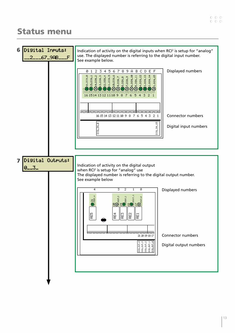
Indication of activity on the digital inputs when RCI2 is setup for “analog” use. The displayed number is referring to the digital input number. See example below.
16 15 14 13 12 1110 9 8 7 6 5 4 3 2 1
16 1514 13 12 1110 9 8 7 6 5 4 3 2 1
DIG_IN_15
DIG_IN_0
10.DIN_6
6.DIN_10
5.DIN_11
8.DIN_8
4.DIN_12
7.DIN_9
1.DIN_15
3.DIN_13
14.DIN_2
15.DIN_1
13.DIN_3
11.DIN_5
12.DIN_4
9.DIN_7
2.DIN_14
16.DIN_0
0 1 2 3 4 5 6 7 8 9 A B C D E F Displayed numbers
Connector numbers
Digital input numbers
Digital Outputs:
0__3_Indication of activity on the digital output when RCI2 is setup for “analog” useThe displayed number is referring to the digital output number. See example below
Displayed numbers
Connector numbers
Digital output numbers
21 20 19 18 17
DIG_OUT_0
19.DOUT_2
20.DOUT_3
18.DOUT_1
21.DOUT_4
01234
DIG_OUT_1
DIG_OUT_2
DIG_OUT_4
DIG_OUT_3
RE1
RE2
RE3
RE4
RE5
20
19
18
17
21
17.DOUT_0
14 15
Analog Inputs:
0=7.53V 1=10.00V
Analog Outputs:
0=00.00V 1=7.89V
Clock: 09:35:47
FRI 2013-11-08
Status menu
8
9
10
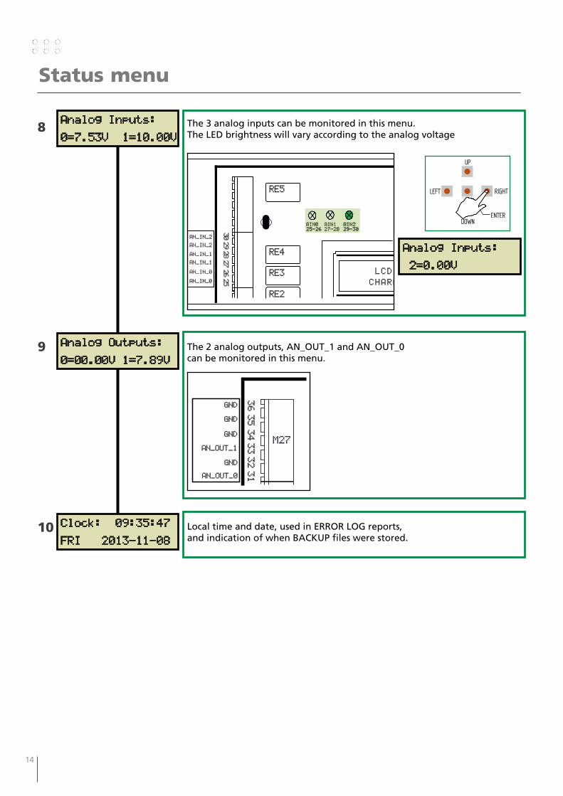
The 3 analog inputs can be monitored in this menu.The LED brightness will vary according to the analog voltage
2928272625
AIN0
25-26
RE2
RE3
RE4
RE5
30
AN_IN_2
AN_IN_2
AN_IN_1
AN_IN_1
AN_IN_0
AN_IN_0
LCD
CHARA
AIN1
27-28
AIN2
29-30
RIGHT
DOWNENTER
LEFT
UP
The 2 analog outputs, AN_OUT_1 and AN_OUT_0 can be monitored in this menu.
3635343332
AN_OUT_0
GND
AN_OUT_1
GND
GND
31
M27
GND
Local time and date, used in ERROR LOG reports, and indication of when BACKUP files were stored.
Analog Inputs:
2=0.00V
14 15
Setup menu
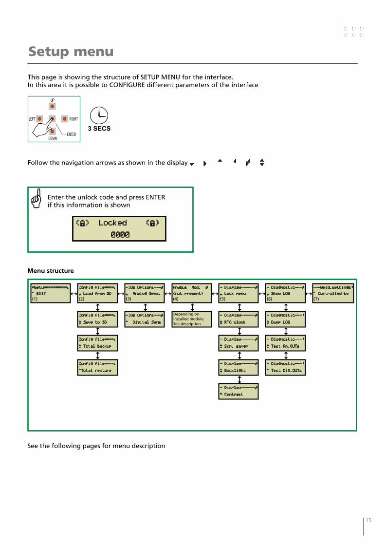
This page is showing the structure of SETUP MENU for the interface. In this area it is possible to CONFIGURE different parameters of the interface
Follow the navigation arrows as shown in the display ¾ Â À Ä Ã ¿
=Setup=========Â
° EXIT
(1)
Config file====Â
¾ Load from SD
(2)
Anybus Mod. Ã
(not present)
(4)
- Diagnostic---Ã
¾ Show LOG
(6)
- Display------Ã
¾ Lock menu
(5)
-IOs Options---Ã
¾ Analog Sens.
(3)
Config file====Â
¿ Save to SD
Depending on installed module. See description
- Diagnostic---Ä
¿ Dump LOG
- Display------Ã
¿ RTC clock
-IOs Options---Ã
À Digital Sens
Config file====Â
¿ Total backup
- Diagnostic---Ä
¿ Test An.OUTs
- Display------Ã
¿ Scr. saver
Config file====Â
ÀTotal restore
- Diagnostic---Ä
À Test Dig.OUTs
- Display------Ã
¿ Backlight
- Display------Ã
À Contrast
RIGHT
DOWNENTER
LEFT
UP
3 SECS
Enter the unlock code and press ENTER if this information is shown
(È) Locked (È)
0000
See the following pages for menu description
Menu structure
---Weld.settingsÄ
° Controlled by
(7)
16 17
Setup menu
MIGA_CFG
ROBOT
1000xxxx.txt
1000xxxx.PDF(configuration file description)
(configuration file)
=Setup=========Â
° Exit
=Setup=========Â
° Exit&Reboot
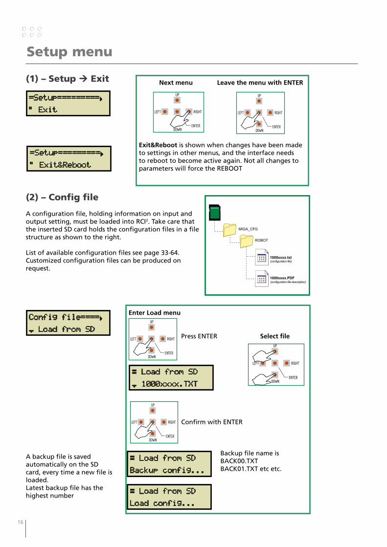
(1) – Setup Exit Next menu Leave the menu with ENTER
Exit&Reboot is shown when changes have been made to settings in other menus, and the interface needs to reboot to become active again. Not all changes to parameters will force the REBOOT
RIGHT
DOWNENTER
LEFT
UP
RIGHT
DOWNENTER
LEFT
UP
(2) – Config file
A configuration file, holding information on input and output setting, must be loaded into RCI2. Take care that the inserted SD card holds the configuration files in a file structure as shown to the right.
List of available configuration files see page 33-64.Customized configuration files can be produced on request.
A backup file is saved automatically on the SD card, every time a new file is loaded.Latest backup file has the highest number
Config file====Â
¾ Load from SD
Enter Load menu
Press ENTER Select file
Confirm with ENTER
Backup file name is BACK00.TXT BACK01.TXT etc etc.
RIGHT
DOWNENTER
LEFT
UP
RIGHT
DOWNENTER
LEFT
UP
Æ Load from SD
¾ 1000xxxx.TXT
Æ Load from SD
Load config...
Æ Load from SD
Backup config...
RIGHT
DOWNENTER
LEFT
UP
16 17
Setup menu
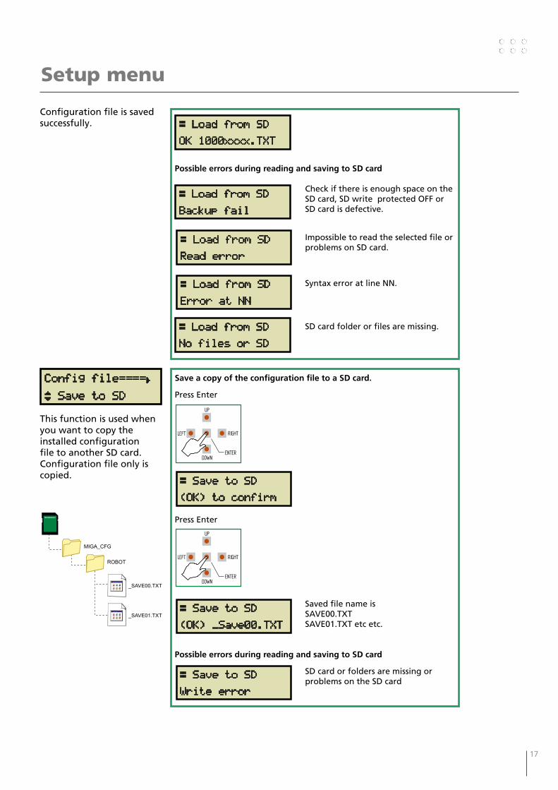
Configuration file is saved successfully. Æ Load from SD
OK 1000xxxx.TXT
Possible errors during reading and saving to SD card
Check if there is enough space on the SD card, SD write protected OFF or SD card is defective.
Impossible to read the selected file or problems on SD card.
Syntax error at line NN.
SD card folder or files are missing.
Æ Load from SD
Backup fail
Æ Load from SD
Read error
Æ Load from SD
Error at NN
Æ Load from SD
No files or SD
Config file====Â
¿ Save to SD
This function is used when you want to copy the installed configuration file to another SD card.Configuration file only is copied.
Save a copy of the configuration file to a SD card.
Press Enter
Press Enter
Saved file name is SAVE00.TXTSAVE01.TXT etc etc.
Possible errors during reading and saving to SD card
SD card or folders are missing or problems on the SD card
RIGHT
DOWNENTER
LEFT
UP
RIGHT
DOWNENTER
LEFT
UP
Æ Save to SD
(OK) _Save00.TXT
Æ Save to SD
Write error
Æ Save to SD
(OK) to confirm
MIGA_CFG
ROBOT
_SAVE00.TXT
_SAVE01.TXT

18 19
Setup menu
A backup of all configurations settings and Anybus network setups are stored on the SD card.This function is useful when replacing the RCI2 after a breakdown, or when cloning of RCI2 is needed.Previous backup file will be overwritten.
A Total backup of all settings to the SD card.
Press Enter
Press Enter
Saved file name is RCI2.BCKsaved at the root of SD card.
Possible errors during backup to SD card
SD card or folders are missing or problems on the SD card
Config file====Â
¿ Backup all
Upload of backup file with all configuration setups and Anybus network setups stored on the SD card.This function is useful when replacing the RCI2 after a breakdown, or when cloning the RCI2 is needed.
Æ Backup
(OK) to confirm
RIGHT
DOWNENTER
LEFT
UP
RIGHT
DOWNENTER
LEFT
UP
Æ Backup
(OK)!
Æ Backup
Write error
Restore settings from backup of all settings to the SD card.
Press Enter
Press Enter
Read file name URI_BCK.BINfrom the root of SD card.
Possible errors during restore from SD card
SD card or folders are missing or problems on the SD card.
Æ Restore
(OK) to confirm
RIGHT
DOWNENTER
LEFT
UP
RIGHT
DOWNENTER
LEFT
UP
Æ Restore
(OK)! Reboot...
Config file====Â
(Read error!)
Config file====Â
À Restore all
RCI2.BCK
18 19
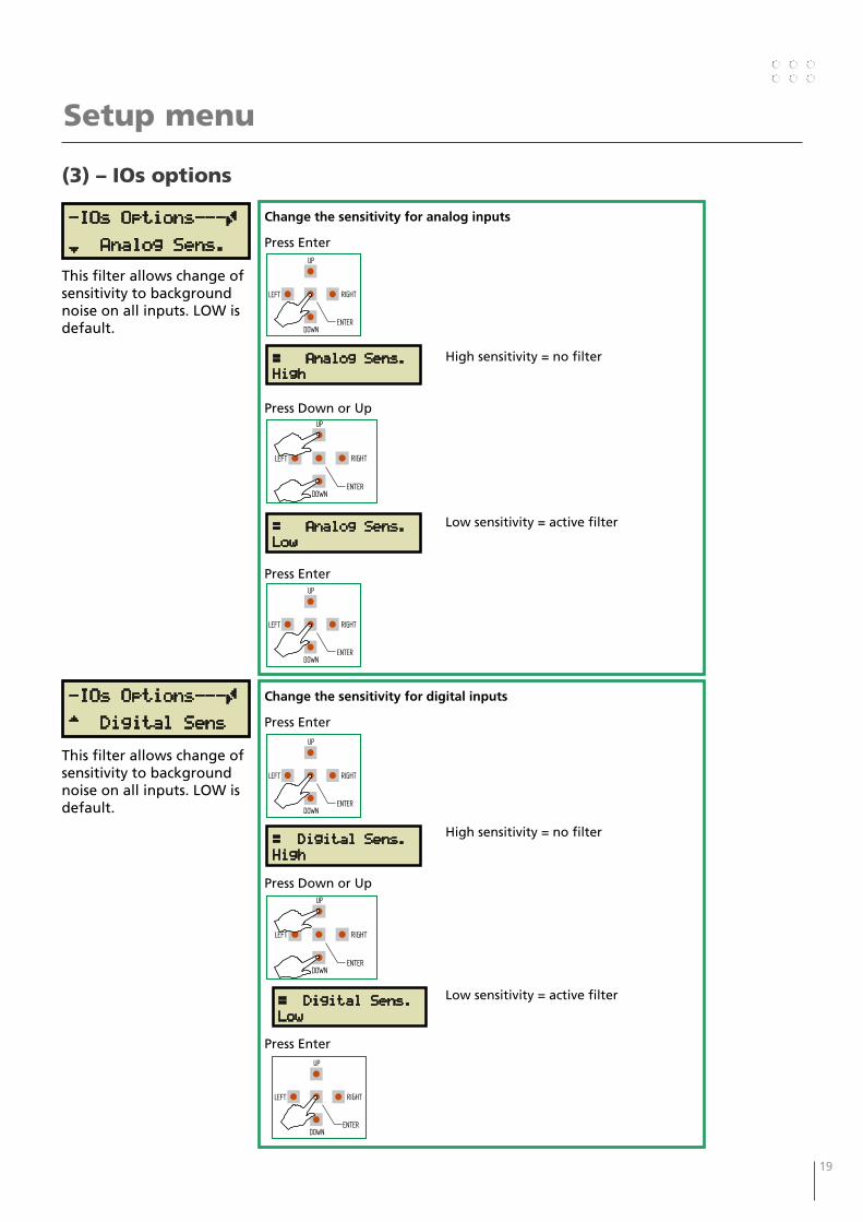
(3) – IOs options
Setup menu
This filter allows change of sensitivity to background noise on all inputs. LOW is default.
Change the sensitivity for analog inputs
Press Enter
High sensitivity = no filter
Press Down or Up
Low sensitivity = active filter
Press Enter
-IOs Options---Ã
¾ Analog Sens.
Æ Analog Sens.High
RIGHT
DOWNENTER
LEFT
UP
Æ Analog Sens.Low
RIGHT
DOWNENTER
LEFT
UP
RIGHT
DOWNENTER
LEFT
UP
This filter allows change of sensitivity to background noise on all inputs. LOW is default.
-IOs Options---Ã
À Digital Sens
Change the sensitivity for digital inputs
Press Enter
High sensitivity = no filter
Press Down or Up
Low sensitivity = active filter
Press Enter
Æ Digital Sens.High
RIGHT
DOWNENTER
LEFT
UP
Æ Digital Sens.Low
RIGHT
DOWNENTER
LEFT
UP
RIGHT
DOWNENTER
LEFT
UP
20 21
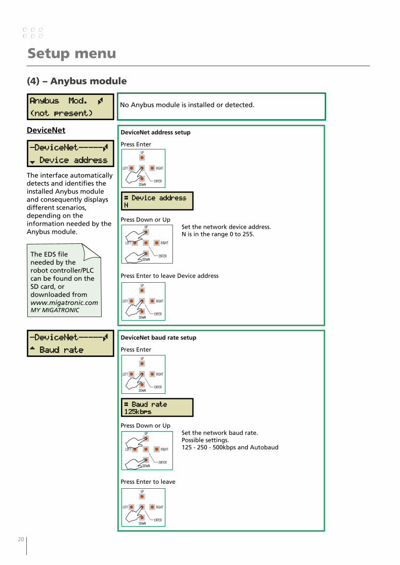
(4) – Anybus module
Setup menu
Anybus Mod. Ã
(not present)No Anybus module is installed or detected.
DeviceNet
-DeviceNet-----Ã
¾ Device address
DeviceNet address setup
Press Enter
Press Down or UpSet the network device address.N is in the range 0 to 255.
Press Enter to leave Device address
Æ Device addressN
RIGHT
DOWNENTER
LEFT
UP
RIGHT
DOWNENTER
LEFT
UP
RIGHT
DOWNENTER
LEFT
UP
The interface automatically detects and identifies the installed Anybus module and consequently displays different scenarios, depending on the information needed by the Anybus module.
DeviceNet baud rate setup
Press Enter
Press Down or UpSet the network baud rate.Possible settings.125 - 250 - 500kbps and Autobaud
Press Enter to leave
Æ Baud rate125kbps
RIGHT
DOWNENTER
LEFT
UP
RIGHT
DOWNENTER
LEFT
UP
RIGHT
DOWNENTER
LEFT
UP
-DeviceNet-----Ã
À Baud rate
The EDS file needed by the robot controller/PLC can be found on the SD card, or downloaded from www.migatronic.comMY MIGATRONIC
20 21
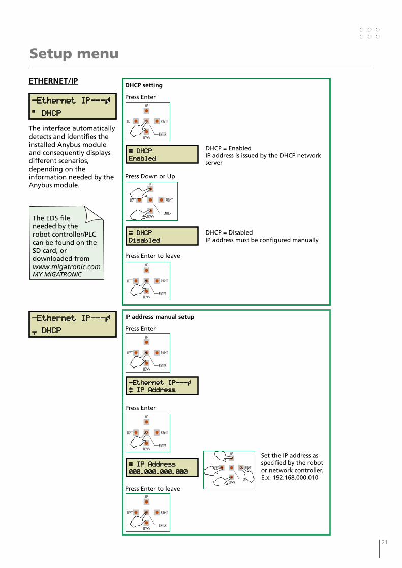
ETHERNET/IP
-Ethernet IP---Ã
° DHCP
DHCP setting
Press Enter
DHCP = EnabledIP address is issued by the DHCP network server
Press Down or Up
DHCP = DisabledIP address must be configured manually
Press Enter to leave
Æ DHCPEnabled
RIGHT
DOWNENTER
LEFT
UP
RIGHT
DOWNENTER
LEFT
UP
RIGHT
DOWNENTER
LEFT
UP
The interface automatically detects and identifies the installed Anybus module and consequently displays different scenarios, depending on the information needed by the Anybus module.
-Ethernet IP---Ã
¾ DHCP
Setup menu
Æ DHCPDisabled
IP address manual setup
Press Enter
Press Enter
Set the IP address as specified by the robot or network controller.E.x. 192.168.000.010
Press Enter to leave
-Ethernet IP---ÿ IP Address
RIGHT
DOWNENTER
LEFT
UP
RIGHT
DOWNENTER
LEFT
UP
Æ IP Address000.000.000.000
RIGHT
DOWNENTER
LEFT
UP
RIGHT
DOWNENTER
LEFT
UP
The EDS file needed by the robot controller/PLC can be found on the SD card, or downloaded from www.migatronic.comMY MIGATRONIC

22 23
Setup menu
IP address manual setup SUBNET MASK
Press Down
Press Enter
Set the IP subnet mask address as specified by the robot or network controller.E.x. 255.255.255.000
Press Enter to leave
-Ethernet IP---ÃÀ Subnet mask
Æ Subnet mask000.000.000.000
RIGHT
DOWNENTER
LEFT
UP
RIGHT
DOWNENTER
LEFT
UP
RIGHT
DOWNENTER
LEFT
UP
RIGHT
DOWNENTER
LEFT
UP
-EtherCAT------Ã
Á Device ID
Device ID setup
Press Enter
Set the Device ID as specified by the robot or network controller.N is in the range 0 to 65535.
Press Enter
RIGHT
DOWNENTER
LEFT
UP
RIGHT
DOWNENTER
LEFT
UP
Æ Device addressN
EtherCAT
RIGHT
DOWNENTER
LEFT
UP
The ESI file needed by the robot controller/PLC can be found on the SD card, or downloaded from www.migatronic.comMY MIGATRONIC
22 23
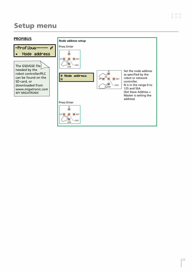
Setup menu
-Profibus----- Ã
Á Node address
Node address setup
Press Enter
Set the node address as specified by the robot or network controller.N is in the range 0 to 125 and SSA(Set Slave Address = Master is setting the address)
Press Enter
RIGHT
DOWNENTER
LEFT
UP
RIGHT
DOWNENTER
LEFT
UP
Æ Node addressN
PROFIBUS
RIGHT
DOWNENTER
LEFT
UP
The GSD/GSE file needed by the robot controller/PLC can be found on the SD card, or downloaded from www.migatronic.comMY MIGATRONIC
24 25
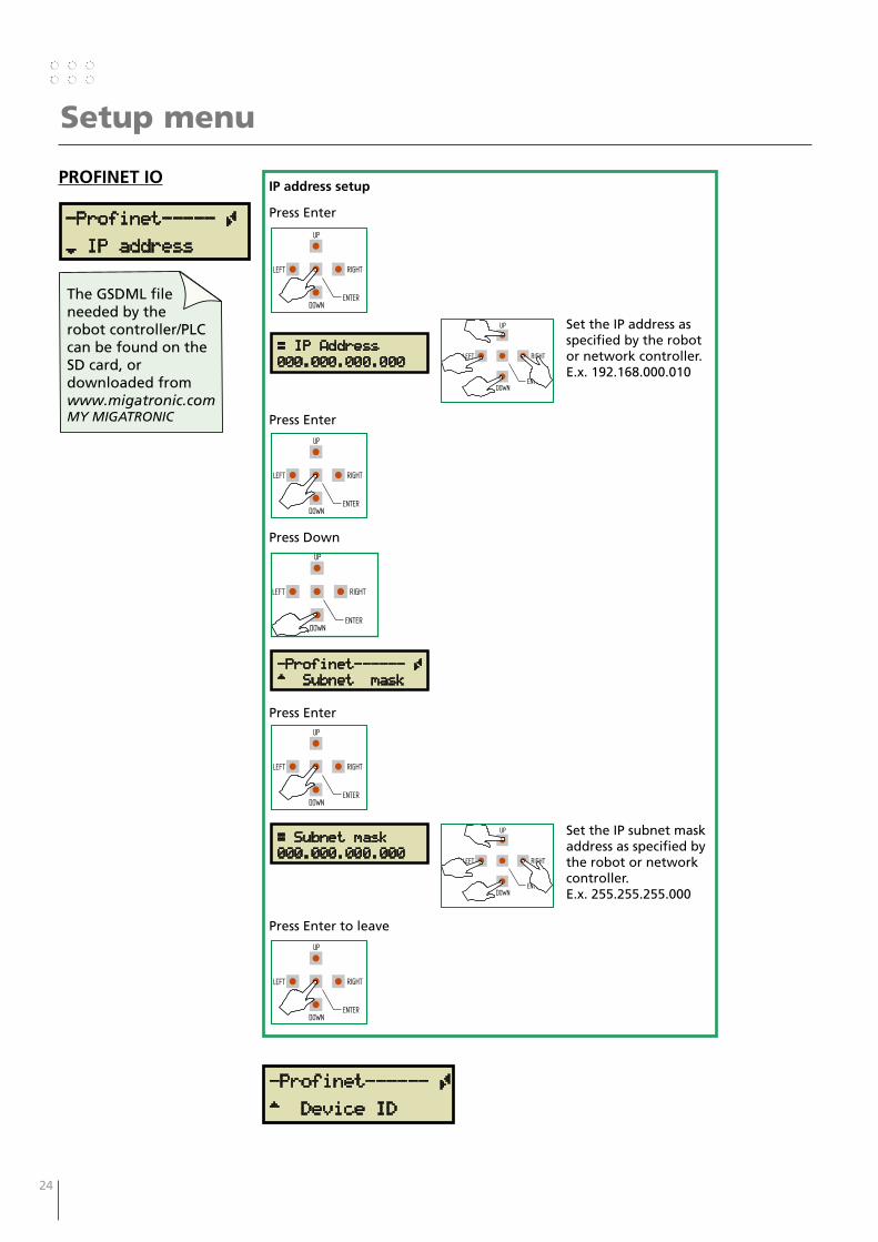
Setup menu
-Profinet----- Ã
¾ IP address
IP address setup
Press Enter
Set the IP address as specified by the robot or network controller.E.x. 192.168.000.010
Press Enter
Press Down
Press Enter
Set the IP subnet mask address as specified by the robot or network controller.E.x. 255.255.255.000
Press Enter to leave
RIGHT
DOWNENTER
LEFT
UP
RIGHT
DOWNENTER
LEFT
UP
Æ IP Address000.000.000.000
PROFINET IO
RIGHT
DOWNENTER
LEFT
UP
RIGHT
DOWNENTER
LEFT
UP
-Profinet------ ÃÀ Subnet mask
RIGHT
DOWNENTER
LEFT
UP
Æ Subnet mask000.000.000.000
RIGHT
DOWNENTER
LEFT
UP
RIGHT
DOWNENTER
LEFT
UP
The GSDML file needed by the robot controller/PLC can be found on the SD card, or downloaded from www.migatronic.comMY MIGATRONIC
-Profinet------ Ã
À Device ID
24 25
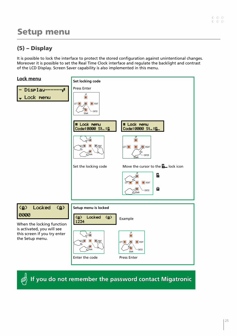
(5) – Display
It is possible to lock the interface to protect the stored configuration against unintentional changes. Moreover it is possible to set the Real Time Clock interface and regulate the backlight and contrast of the LCD Display. Screen Saver capability is also implemented in this menu.
Setup menu
- Display------Ã
¾ Lock menu
Set locking code
Press Enter
Set the locking code Move the cursor to the É_ lock icon
É
È
RIGHT
DOWNENTER
LEFT
UP
Æ Lock menuCode:0000 St.:É
Lock menu
RIGHT
DOWNENTER
LEFT
UP
Æ Lock menuCode:0000 St.:É_
RIGHT
DOWNENTER
LEFT
UP
RIGHT
DOWNENTER
LEFT
UP
(È) Locked (È)
0000
When the locking function is activated, you will see this screen if you try enter the Setup menu.
Setup menu is locked
Example
Enter the code Press Enter
(È) Locked (È)1234
RIGHT
DOWNENTER
LEFT
UP
RIGHT
DOWNENTER
LEFT
UP
If you do not remember the password contact Migatronic
26 27
Setup menu
-Display-------Ã
¿ RTC clock
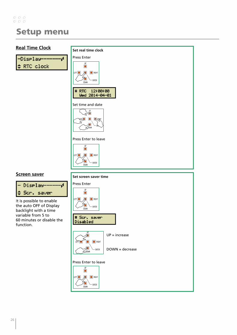
Real Time Clock Set real time clock
Press Enter
Set time and date
Press Enter to leave
RIGHT
DOWNENTER
LEFT
UP
RIGHT
DOWNENTER
LEFT
UP
Æ RTC 12:00:00 Wed 2014-04-01
RIGHT
DOWNENTER
LEFT
UP
RIGHT
DOWNENTER
LEFT
UP
- Display------Ã
¿ Scr. saver
Screen saver Set screen saver time
Press Enter
UP = increase
DOWN = decrease
Press Enter to leave
RIGHT
DOWNENTER
LEFT
UP
RIGHT
DOWNENTER
LEFT
UP
Æ Scr. saverDisabled
It is possible to enable the auto OFF of Display backlight with a time variable from 5 to 60 minutes or disable the function.

26 27
Setup menu
- Display------Ã
¿ Backlight
Backlight
RIGHT
DOWNENTER
LEFT
UP
Set the intensity of backlight
Press Enter
UP = increase
DOWN = decrease
Press Enter to leave
RIGHT
DOWNENTER
LEFT
UP
RIGHT
DOWNENTER
LEFT
UP
Æ Backlight60%
- Display------Ã
À Contrast
Contrast
RIGHT
DOWNENTER
LEFT
UP
Set the intensity of backlight
Press Enter
UP = increase
DOWN = decrease
Press Enter to leave
RIGHT
DOWNENTER
LEFT
UP
RIGHT
DOWNENTER
LEFT
UP
Æ Contrast40%
Please note that the contrast of display is
strongly depending from the temperature of LCD display.

28 29
Setup menu
(6) – Diagnostic
In this area it is possible to go through the error list and save it on the SD card.Other 2 functions are dedicated to manually force the status of Analog and Digital outputs and Mixed Digital/Analog interface for debugging purposes: data sent to the interface by the welding machine are ignored.
-Diagnostic----Ã
¾ Show LOG
Set the intensity of backlight
Press Enter
r
Scroll through the list. Ex. 005/008First number is the current error displayed.Second number is the total amount of saved errors.E12.13 is the error code.
The time error Error came description
Press Enter to leave
RIGHT
DOWNENTER
LEFT
UP
Æ Show LOG005/008=>E02.13
Show LOG
RIGHT
DOWNENTER
LEFT
UP
Æ Show LOG2014-04-01 15:19
RIGHT
DOWNENTER
LEFT
UP
RIGHT
DOWNENTER
LEFT
UP
Æ Show LOGCAN BUS Warning
RIGHT
DOWNENTER
LEFT
UP
28 29
Setup menu
-Diagnostic----Ä
¿ Dump LOG
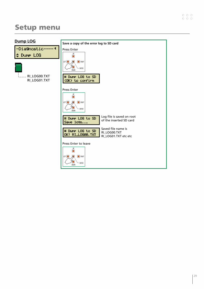
Dump LOG
RI_LOG00.TXTRI_LOG01.TXT
Save a copy of the error log to SD card
Press Enter
Press Enter
Log file is saved on root of the inserted SD card
Saved file name is RI_LOG00.TXTRI_LOG01.TXT etc etc
Press Enter to leave
Æ Dump LOG to SD(OK) to confirm
RIGHT
DOWNENTER
LEFT
UP
Æ Dump LOG to SDSave logs...
RIGHT
DOWNENTER
LEFT
UP
Æ Dump LOG to SDOK! RI_LOG00.TXT
RIGHT
DOWNENTER
LEFT
UP
30 31
Setup menu
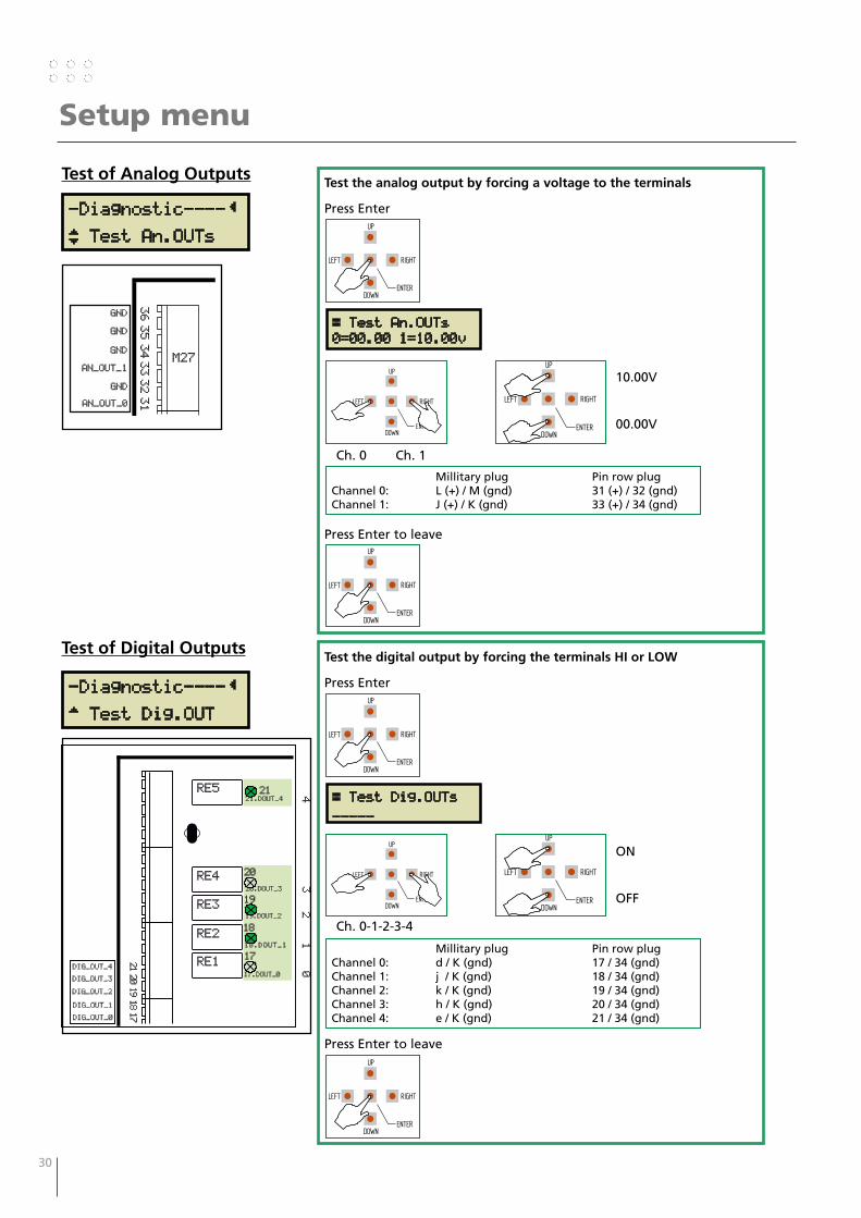
Test of Analog Outputs
-Diagnostic----Ä
¿ Test An.OUTs
Test the analog output by forcing a voltage to the terminals
Press Enter
10.00V
00.00V
Ch. 0 Ch. 1
Press Enter to leave
RIGHT
DOWNENTER
LEFT
UP
Æ Test An.OUTs0=00.00 1=10.00v
RIGHT
DOWNENTER
LEFT
UP
RIGHT
DOWNENTER
LEFT
UP
Millitary plug Pin row plugChannel 0: L (+) / M (gnd) 31 (+) / 32 (gnd)Channel 1: J (+) / K (gnd) 33 (+) / 34 (gnd)
RIGHT
DOWNENTER
LEFT
UP
3635343332
AN_OUT_0
GND
AN_OUT_1
GND
GND
31
M27
GND
Test of Digital Outputs
-Diagnostic----Ä
À Test Dig.OUT2120191817
DIG_OUT_0
19.DOUT_2
20.DOUT_3
18.DOUT_1
21.DOUT_4
01
23
4
DIG_OUT_1
DIG_OUT_2
DIG_OUT_4
DIG_OUT_3
RE1
RE2
RE3
RE4
RE5
20
19
18
17
21
17.DOUT_0
Test the digital output by forcing the terminals HI or LOW
Press Enter
ON
OFF
Ch. 0-1-2-3-4
Press Enter to leave
RIGHT
DOWNENTER
LEFT
UP
Æ Test Dig.OUTs_____
RIGHT
DOWNENTER
LEFT
UP
RIGHT
DOWNENTER
LEFT
UP
Millitary plug Pin row plugChannel 0: d / K (gnd) 17 / 34 (gnd)Channel 1: j / K (gnd) 18 / 34 (gnd)Channel 2: k / K (gnd) 19 / 34 (gnd)Channel 3: h / K (gnd) 20 / 34 (gnd)Channel 4: e / K (gnd) 21 / 34 (gnd)
RIGHT
DOWNENTER
LEFT
UP
30 31
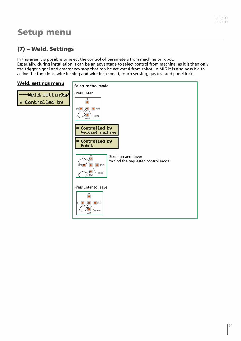
(7) – Weld. Settings
In this area it is possible to select the control of parameters from machine or robot. Especially, during installation it can be an advantage to select control from machine, as it is then only the trigger signal and emergency stop that can be activated from robot. In MIG it is also possible to active the functions: wire inching and wire inch speed, touch sensing, gas test and panel lock.
---Weld.settingsÃ
Á Controlled by
Select control mode
Press Enter
Scroll up and down to find the requested control mode
Press Enter to leave
RIGHT
DOWNENTER
LEFT
UP
Weld. settings menu
Setup menu
Æ Controlled by Welding machine
RIGHT
DOWNENTER
LEFT
UP
Æ Controlled by Robot
RIGHT
DOWNENTER
LEFT
UP
32 33
Robot / PLC setup
MIGA_CFG
DOCUMENTS
Devicenet
EtherCAT
Profibus
Profinet
Ethernet-IP
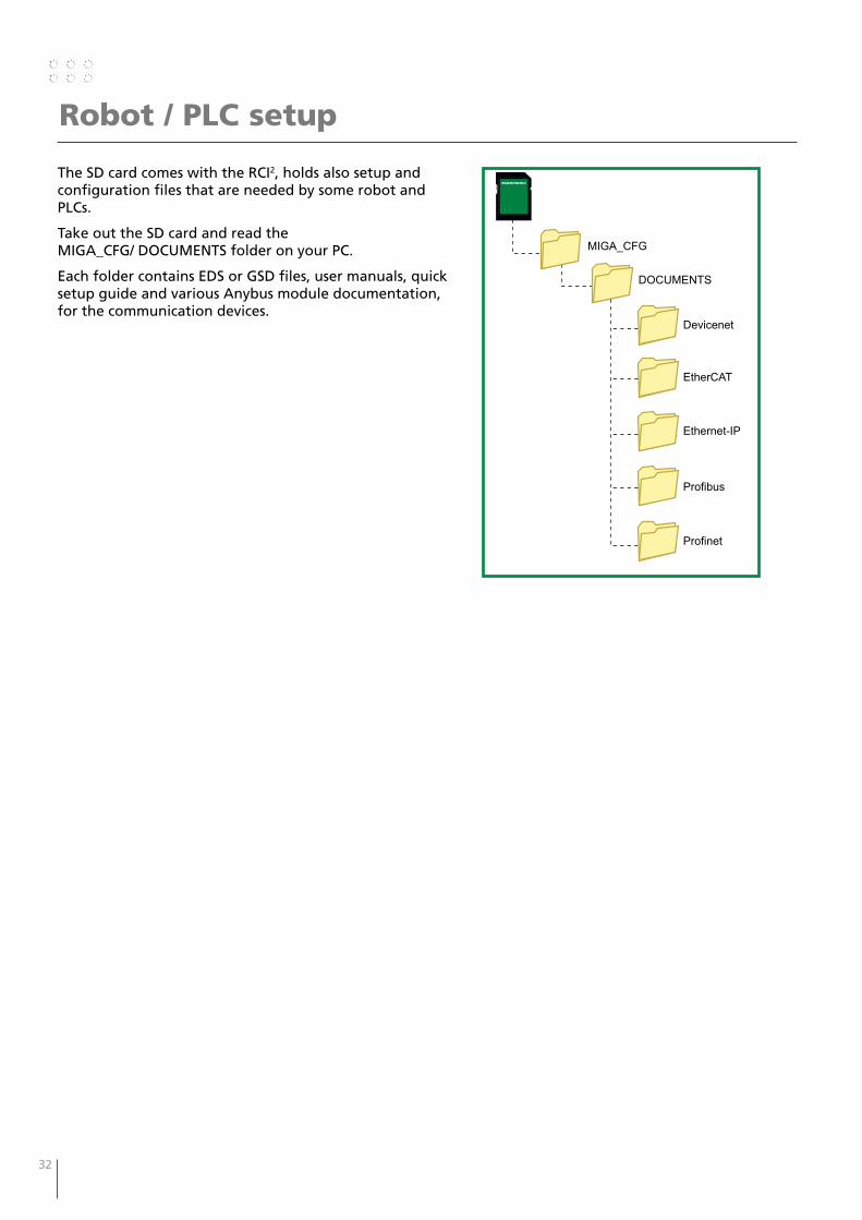
The SD card comes with the RCI2, holds also setup and configuration files that are needed by some robot and PLCs.
Take out the SD card and read the MIGA_CFG/ DOCUMENTS folder on your PC.
Each folder contains EDS or GSD files, user manuals, quick setup guide and various Anybus module documentation, for the communication devices.

32 33
Analog Configuration file – PI TIG Standard
PI DC or AC/DC with/without CWF – 10010601
Analog Configuration - 10010601 v1.02 PI DC or AC/DC with/without CWF
10010601 Page 1 of 2
DIGITAL INPUTS (JMP1=Active-HIGH)
Pin# / Military
Plug
Symbol Name Description Active
1 / m DIN15 !Quick-Stop Emergency stop When input is H the machine can operate. When input is L the welding will stop instantly without slope down and the machine cannot start welding; the CWF also stops feeding without retract.
L
2 / n DIN14 !Panel-Lock Panel locking When input is H machine and CWF panels can be operated. When input is L panels are locked (panels can be unlocked also using “User-Menu”).
L
3 / Z DIN13 Pulse-Mode-Bit1 Current Pulse Mode Selection Select current pulse mode based on inputs combination: (Bit1)LL(Bit0) No pulsation (Bit1)LH(Bit0) Slow-Pulse (Bit1)HL(Bit0) Fast-Pulse (Bit1)HH(Bit0) Synergic-Pulse
xx 4 / N DIN12 Pulse-Mode-Bit0
5 / P DIN11 Process-Selection Welding Process Selection When input is L selects TIG-DC process. When input is H selects TIG-AC process.
H
6 / T DIN10 7 / C DIN9 Program-Bit3 Welding Program Selection
Select program number based on inputs combination: (Bit3)LLLL(Bit0) Selected from machine (Bit3)LLLH(Bit0) Select program #1 (Bit3)LLHL(Bit0) Select program #2 (Bit3)LLHH(Bit0) Select program #3 … (Bit3)HHHH(Bit0) Select program #15
xxxx 8 / D DIN8 Program-Bit2 9 / G DIN7 Program-Bit1 10 / H DIN6 Program-Bit0
11 / X DIN5 Pulse-Wire Enable CWF Wire Pulse* When input is H the pulsation of wire is enabled according to the CWF settings. If Slow-Pulse with correct timings (see user manual) is enabled the wire-pulse is synchronized with current.
H
12 / W DIN4 Error-Reset Active Errors Reset When input makes a L-to-H transition all errors on PI, CWF and interface are cleared. If errors are not clearable error signals remain active.
H
13 / U DIN3 Fwd-Wire-Inch Forward Wire Inching* When arc is off wire can be jogged forward from the CWF by setting this input H.
H
14 / V DIN2 Rev-Wire-Inch Reverse Wire Inching* When arc is off wire can be jogged backward in the CWF by setting this input H.
H
15 / S DIN1 Gas-Purge Gas Purge Control Set this input H to start Shield and Plasma Gas purge. This input has no effects during welding.
H
16 / R DIN0 Arc-Trigger Start Welding Arc When input is H welding is started (other tasks as wire-inch, gas purge etc. are aborted). If Quick-Stop is active arc is not started. When input going H-to-L, the actual wire-speed is latched disregarding the analogue value at the analog input.
H
34 35
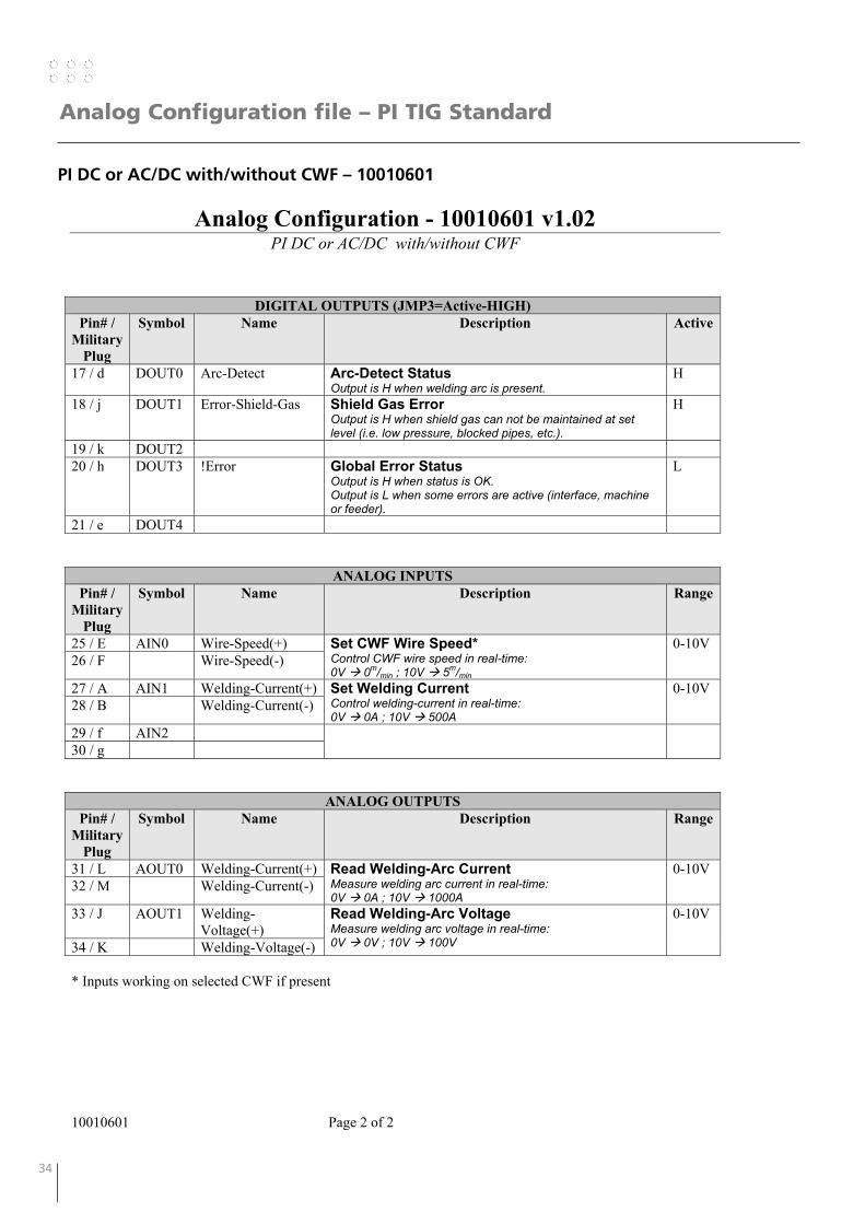
Analog Configuration file – PI TIG Standard
PI DC or AC/DC with/without CWF – 10010601
Analog Configuration - 10010601 v1.02 PI DC or AC/DC with/without CWF
10010601 Page 2 of 2
DIGITAL OUTPUTS (JMP3=Active-HIGH) Pin# /
Military Plug
Symbol Name Description Active
17 / d DOUT0 Arc-Detect Arc-Detect Status Output is H when welding arc is present.
H
18 / j DOUT1 Error-Shield-Gas Shield Gas Error Output is H when shield gas can not be maintained at set level (i.e. low pressure, blocked pipes, etc.).
H
19 / k DOUT2 20 / h DOUT3 !Error Global Error Status
Output is H when status is OK. Output is L when some errors are active (interface, machine or feeder).
L
21 / e DOUT4
ANALOG INPUTS Pin# /
Military Plug
Symbol Name Description Range
25 / E AIN0 Wire-Speed(+) Set CWF Wire Speed* Control CWF wire speed in real-time: 0V 0m/min ; 10V 5m/min
0-10V 26 / F Wire-Speed(-)
27 / A AIN1 Welding-Current(+) Set Welding Current Control welding-current in real-time: 0V 0A ; 10V 500A
0-10V 28 / B Welding-Current(-)
29 / f AIN2 30 / g
ANALOG OUTPUTS Pin# /
Military Plug
Symbol Name Description Range
31 / L AOUT0 Welding-Current(+) Read Welding-Arc Current Measure welding arc current in real-time: 0V 0A ; 10V 1000A
0-10V 32 / M Welding-Current(-)
33 / J AOUT1 Welding-Voltage(+)
Read Welding-Arc Voltage Measure welding arc voltage in real-time: 0V 0V ; 10V 100V
0-10V
34 / K Welding-Voltage(-) * Inputs working on selected CWF if present
34 35
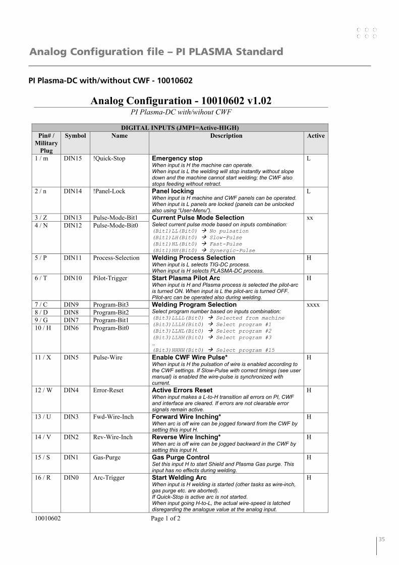
Analog Configuration file – PI PLASMA Standard
PI Plasma-DC with/without CWF - 10010602
Analog Configuration - 10010602 v1.02 PI Plasma-DC with/wihout CWF
10010602 Page 1 of 2
DIGITAL INPUTS (JMP1=Active-HIGH)
Pin# / Military
Plug
Symbol Name Description Active
1 / m DIN15 !Quick-Stop Emergency stop When input is H the machine can operate. When input is L the welding will stop instantly without slope down and the machine cannot start welding; the CWF also stops feeding without retract.
L
2 / n DIN14 !Panel-Lock Panel locking When input is H machine and CWF panels can be operated. When input is L panels are locked (panels can be unlocked also using “User-Menu”).
L
3 / Z DIN13 Pulse-Mode-Bit1 Current Pulse Mode Selection Select current pulse mode based on inputs combination: (Bit1)LL(Bit0) No pulsation (Bit1)LH(Bit0) Slow-Pulse (Bit1)HL(Bit0) Fast-Pulse (Bit1)HH(Bit0) Synergic-Pulse
xx 4 / N DIN12 Pulse-Mode-Bit0
5 / P DIN11 Process-Selection Welding Process Selection When input is L selects TIG-DC process. When input is H selects PLASMA-DC process.
H
6 / T DIN10 Pilot-Trigger Start Plasma Pilot Arc When input is H and Plasma process is selected the pilot-arc is turned ON. When input is L the pilot-arc is turned OFF. Pilot-arc can be operated also during welding.
H
7 / C DIN9 Program-Bit3 Welding Program Selection Select program number based on inputs combination: (Bit3)LLLL(Bit0) Selected from machine (Bit3)LLLH(Bit0) Select program #1 (Bit3)LLHL(Bit0) Select program #2 (Bit3)LLHH(Bit0) Select program #3 … (Bit3)HHHH(Bit0) Select program #15
xxxx 8 / D DIN8 Program-Bit2 9 / G DIN7 Program-Bit1 10 / H DIN6 Program-Bit0
11 / X DIN5 Pulse-Wire Enable CWF Wire Pulse* When input is H the pulsation of wire is enabled according to the CWF settings. If Slow-Pulse with correct timings (see user manual) is enabled the wire-pulse is synchronized with current.
H
12 / W DIN4 Error-Reset Active Errors Reset When input makes a L-to-H transition all errors on PI, CWF and interface are cleared. If errors are not clearable error signals remain active.
H
13 / U DIN3 Fwd-Wire-Inch Forward Wire Inching* When arc is off wire can be jogged forward from the CWF by setting this input H.
H
14 / V DIN2 Rev-Wire-Inch Reverse Wire Inching* When arc is off wire can be jogged backward in the CWF by setting this input H.
H
15 / S DIN1 Gas-Purge Gas Purge Control Set this input H to start Shield and Plasma Gas purge. This input has no effects during welding.
H
16 / R DIN0 Arc-Trigger Start Welding Arc When input is H welding is started (other tasks as wire-inch, gas purge etc. are aborted). If Quick-Stop is active arc is not started. When input going H-to-L, the actual wire-speed is latched disregarding the analogue value at the analog input.
H
36 37
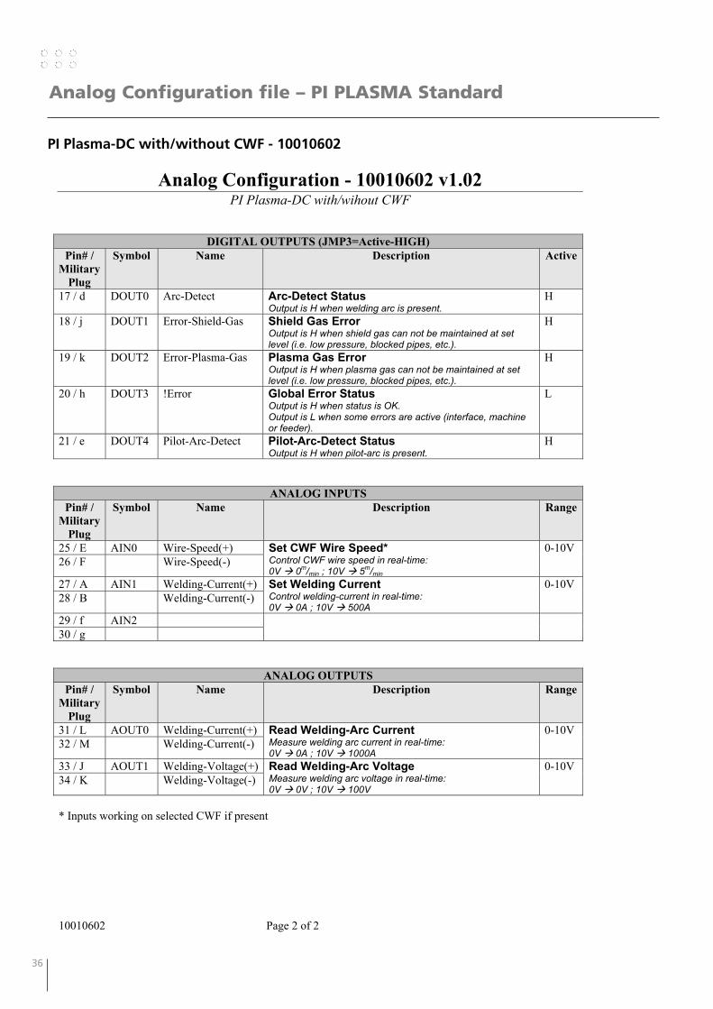
Analog Configuration file – PI PLASMA Standard
PI Plasma-DC with/without CWF - 10010602
Analog Configuration - 10010602 v1.02 PI Plasma-DC with/wihout CWF
10010602 Page 2 of 2
DIGITAL OUTPUTS (JMP3=Active-HIGH) Pin# /
Military Plug
Symbol Name Description Active
17 / d DOUT0 Arc-Detect Arc-Detect Status Output is H when welding arc is present.
H
18 / j DOUT1 Error-Shield-Gas Shield Gas Error Output is H when shield gas can not be maintained at set level (i.e. low pressure, blocked pipes, etc.).
H
19 / k DOUT2 Error-Plasma-Gas Plasma Gas Error Output is H when plasma gas can not be maintained at set level (i.e. low pressure, blocked pipes, etc.).
H
20 / h DOUT3 !Error Global Error Status Output is H when status is OK. Output is L when some errors are active (interface, machine or feeder).
L
21 / e DOUT4 Pilot-Arc-Detect Pilot-Arc-Detect Status Output is H when pilot-arc is present.
H
ANALOG INPUTS Pin# /
Military Plug
Symbol Name Description Range
25 / E AIN0 Wire-Speed(+) Set CWF Wire Speed* Control CWF wire speed in real-time: 0V 0m/min ; 10V 5m/min
0-10V 26 / F Wire-Speed(-)
27 / A AIN1 Welding-Current(+) Set Welding Current Control welding-current in real-time: 0V 0A ; 10V 500A
0-10V 28 / B Welding-Current(-)
29 / f AIN2 30 / g
ANALOG OUTPUTS Pin# /
Military Plug
Symbol Name Description Range
31 / L AOUT0 Welding-Current(+) Read Welding-Arc Current Measure welding arc current in real-time: 0V 0A ; 10V 1000A
0-10V 32 / M Welding-Current(-)
33 / J AOUT1 Welding-Voltage(+) Read Welding-Arc Voltage Measure welding arc voltage in real-time: 0V 0V ; 10V 100V
0-10V 34 / K Welding-Voltage(-)
* Inputs working on selected CWF if present
36 37
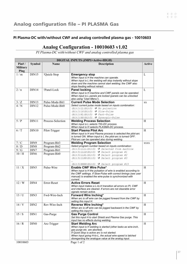
Analog configuration file – PI PLASMA Gas
PI Plasma-DC with/without CWF and analog controlled plasma gas - 10010603
Analog Configuration - 10010603 v1.02 PI Plasma-DC with/without CWF and analog controlled plasma gas
10010603 Page 1 of 2
DIGITAL INPUTS (JMP1=Active-HIGH)
Pin# / Military
Plug
Symbol Name Description Active
1 / m DIN15 !Quick-Stop Emergency stop When input is H the machine can operate. When input is L the welding will stop instantly without slope down and the machine cannot start welding; the CWF also stops feeding without retract.
L
2 / n DIN14 !Panel-Lock Panel locking When input is H machine and CWF panels can be operated. When input is L panels are locked (panels can be unlocked also using “User-Menu”).
L
3 / Z DIN13 Pulse-Mode-Bit1 Current Pulse Mode Selection Select current pulse mode based on inputs combination: (Bit1)LL(Bit0) No pulsation (Bit1)LH(Bit0) Slow-Pulse (Bit1)HL(Bit0) Fast-Pulse (Bit1)HH(Bit0) Synergic-Pulse
xx 4 / N DIN12 Pulse-Mode-Bit0
5 / P DIN11 Process-Selection Welding Process Selection When input is L selects TIG-DC process. When input is H selects PLASMA-DC process.
H
6 / T DIN10 Pilot-Trigger Start Plasma Pilot Arc When input is H and Plasma process is selected the pilot-arc is turned ON. When input is L the pilot-arc is turned OFF. Pilot-arc can be operated also during welding.
H
7 / C DIN9 Program-Bit3 Welding Program Selection Select program number based on inputs combination: (Bit3)LLLL(Bit0) Selected from machine (Bit3)LLLH(Bit0) Select program #1 (Bit3)LLHL(Bit0) Select program #2 (Bit3)LLHH(Bit0) Select program #3 … (Bit3)HHHH(Bit0) Select program #15
xxxx 8 / D DIN8 Program-Bit2 9 / G DIN7 Program-Bit1 10 / H DIN6 Program-Bit0
11 / X DIN5 Pulse-Wire Enable CWF Wire Pulse* When input is H the pulsation of wire is enabled according to the CWF settings. If Slow-Pulse with correct timings (see user manual) is enabled the wire-pulse is synchronized with current.
H
12 / W DIN4 Error-Reset Active Errors Reset When input makes a L-to-H transition all errors on PI, CWF and interface are cleared. If errors are not clearable error signals remain active.
H
13 / U DIN3 Fwd-Wire-Inch Forward Wire Inching* When arc is off wire can be jogged forward from the CWF by setting this input H.
H
14 / V DIN2 Rev-Wire-Inch Reverse Wire Inching* When arc is off wire can be jogged backward in the CWF by setting this input H.
H
15 / S DIN1 Gas-Purge Gas Purge Control Set this input H to start Shield and Plasma Gas purge. This input has no effects during welding.
H
16 / R DIN0 Arc-Trigger Start Welding Arc When input is H welding is started (other tasks as wire-inch, gas purge etc. are aborted). If Quick-Stop is active arc is not started. When input going H-to-L, the actual wire-speed is latched disregarding the analogue value at the analog input.
H
38 39
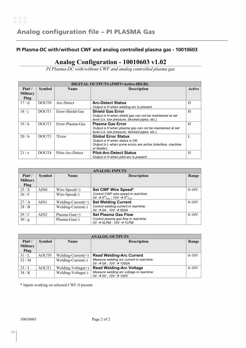
Analog configuration file – PI PLASMA Gas
PI Plasma-DC with/without CWF and analog controlled plasma gas - 10010603
Analog Configuration - 10010603 v1.02 PI Plasma-DC with/without CWF and analog controlled plasma gas
10010603 Page 2 of 2
DIGITAL OUTPUTS (JMP3=Active-HIGH) Pin# /
Military Plug
Symbol Name Description Active
17 / d DOUT0 Arc-Detect Arc-Detect Status Output is H when welding arc is present.
H
18 / j DOUT1 Error-Shield-Gas Shield Gas Error Output is H when shield gas can not be maintained at set level (i.e. low pressure, blocked pipes, etc.).
H
19 / k DOUT2 Error-Plasma-Gas Plasma Gas Error Output is H when plasma gas can not be maintained at set level (i.e. low pressure, blocked pipes, etc.).
H
20 / h DOUT3 !Error Global Error Status Output is H when status is OK. Output is L when some errors are active (interface, machine or feeder).
L
21 / e DOUT4 Pilot-Arc-Detect Pilot-Arc-Detect Status Output is H when pilot-arc is present.
H
ANALOG INPUTS Pin# /
Military Plug
Symbol Name Description Range
25 / E AIN0 Wire-Speed(+) Set CWF Wire Speed* Control CWF wire speed in real-time: 0V 0m/min ; 10V 5m/min
0-10V 26 / F Wire-Speed(-)
27 / A AIN1 Welding-Current(+) Set Welding Current Control welding-current in real-time: 0V 0A ; 10V 500A
0-10V 28 / B Welding-Current(-)
29 / f AIN2 Plasma-Gas(+) Set Plasma Gas Flow Control plasma gas flow in real-time: 0V 0LPM ; 10V 7LPM
0-10V 30 / g Plasma-Gas(-)
ANALOG OUTPUTS Pin# /
Military Plug
Symbol Name Description Range
31 / L AOUT0 Welding-Current(+) Read Welding-Arc Current Measure welding arc current in real-time: 0V 0A ; 10V 1000A
0-10V 32 / M Welding-Current(-)
33 / J AOUT1 Welding-Voltage(+) Read Welding-Arc Voltage Measure welding arc voltage in real-time: 0V 0V ; 10V 100V
0-10V 34 / K Welding-Voltage(-)
* Inputs working on selected CWF if present
38 39
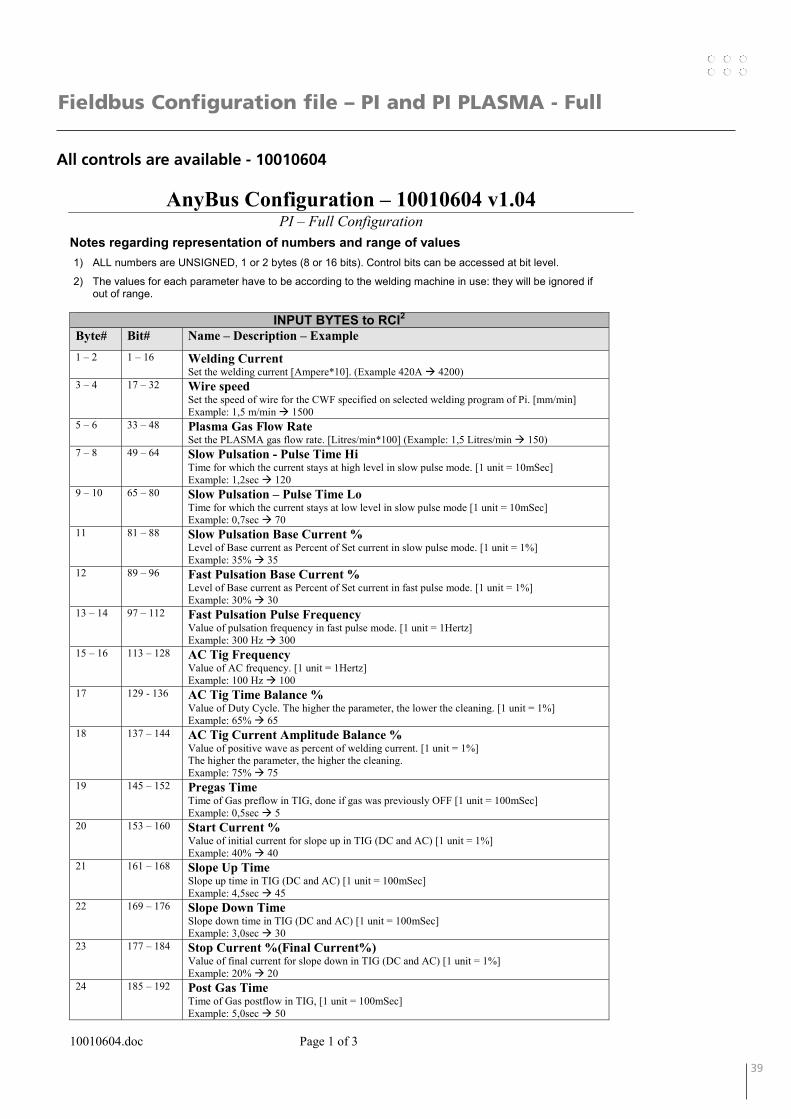
Fieldbus Configuration file – PI and PI PLASMA - Full
All controls are available - 10010604
AnyBus Configuration – 10010604 v1.04 PI – Full Configuration
10010604.doc Page 1 of 3
Notes regarding representation of numbers and range of values 1) ALL numbers are UNSIGNED, 1 or 2 bytes (8 or 16 bits). Control bits can be accessed at bit level.
2) The values for each parameter have to be according to the welding machine in use: they will be ignored if out of range.
INPUT BYTES to RCI2Byte# Bit# Name – Description – Example1 – 2 1 – 16 Welding Current
Set the welding current [Ampere*10]. (Example 420A 4200) 3 – 4 17 – 32 Wire speed
Set the speed of wire for the CWF specified on selected welding program of Pi. [mm/min] Example: 1,5 m/min 1500
5 – 6 33 – 48 Plasma Gas Flow Rate Set the PLASMA gas flow rate. [Litres/min*100] (Example: 1,5 Litres/min 150)
7 – 8 49 – 64 Slow Pulsation - Pulse Time Hi Time for which the current stays at high level in slow pulse mode. [1 unit = 10mSec] Example: 1,2sec 120
9 – 10 65 – 80 Slow Pulsation – Pulse Time Lo Time for which the current stays at low level in slow pulse mode [1 unit = 10mSec] Example: 0,7sec 70
11 81 – 88 Slow Pulsation Base Current % Level of Base current as Percent of Set current in slow pulse mode. [1 unit = 1%] Example: 35% 35
12 89 – 96 Fast Pulsation Base Current % Level of Base current as Percent of Set current in fast pulse mode. [1 unit = 1%] Example: 30% 30
13 – 14 97 – 112 Fast Pulsation Pulse Frequency Value of pulsation frequency in fast pulse mode. [1 unit = 1Hertz] Example: 300 Hz 300
15 – 16 113 – 128 AC Tig Frequency Value of AC frequency. [1 unit = 1Hertz] Example: 100 Hz 100
17 129 - 136 AC Tig Time Balance % Value of Duty Cycle. The higher the parameter, the lower the cleaning. [1 unit = 1%] Example: 65% 65
18 137 – 144 AC Tig Current Amplitude Balance % Value of positive wave as percent of welding current. [1 unit = 1%] The higher the parameter, the higher the cleaning. Example: 75% 75
19 145 – 152 Pregas Time Time of Gas preflow in TIG, done if gas was previously OFF [1 unit = 100mSec] Example: 0,5sec 5
20 153 – 160 Start Current % Value of initial current for slope up in TIG (DC and AC) [1 unit = 1%] Example: 40% 40
21 161 – 168 Slope Up Time Slope up time in TIG (DC and AC) [1 unit = 100mSec]Example: 4,5sec 45
22 169 – 176 Slope Down Time Slope down time in TIG (DC and AC) [1 unit = 100mSec] Example: 3,0sec 30
23 177 – 184 Stop Current %(Final Current%) Value of final current for slope down in TIG (DC and AC) [1 unit = 1%] Example: 20% 20
24 185 – 192 Post Gas Time Time of Gas postflow in TIG, [1 unit = 100mSec] Example: 5,0sec 50
40 41
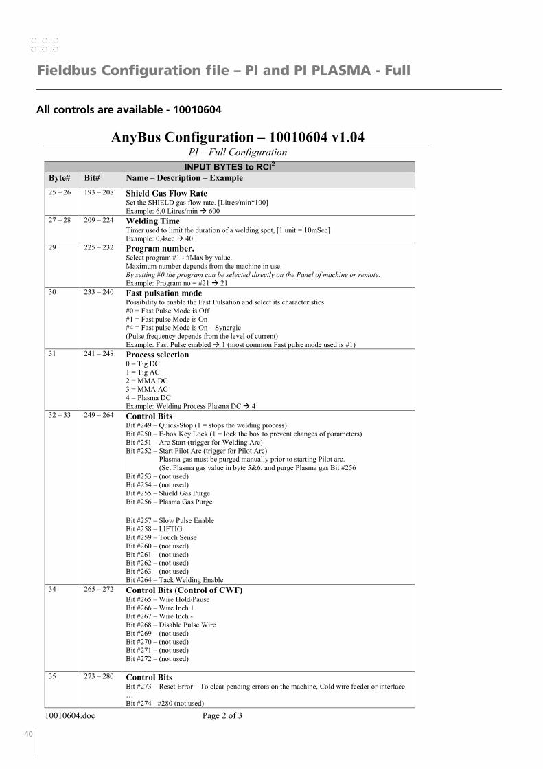
Fieldbus Configuration file – PI and PI PLASMA - Full
All controls are available - 10010604
AnyBus Configuration – 10010604 v1.04 PI – Full Configuration
10010604.doc Page 2 of 3
INPUT BYTES to RCI2Byte# Bit# Name – Description – Example25 – 26 193 – 208 Shield Gas Flow Rate
Set the SHIELD gas flow rate. [Litres/min*100] Example: 6,0 Litres/min 600
27 – 28 209 – 224 Welding Time Timer used to limit the duration of a welding spot, [1 unit = 10mSec] Example: 0,4sec 40
29 225 – 232 Program number. Select program #1 - #Max by value. Maximum number depends from the machine in use. By setting #0 the program can be selected directly on the Panel of machine or remote. Example: Program no = #21 21
30 233 – 240 Fast pulsation mode Possibility to enable the Fast Pulsation and select its characteristics #0 = Fast Pulse Mode is Off #1 = Fast pulse Mode is On #4 = Fast pulse Mode is On – Synergic (Pulse frequency depends from the level of current)Example: Fast Pulse enabled 1 (most common Fast pulse mode used is #1)
31 241 – 248 Process selection 0 = Tig DC 1 = Tig AC 2 = MMA DC 3 = MMA AC 4 = Plasma DC Example: Welding Process Plasma DC 4
32 – 33 249 – 264 Control Bits Bit #249 – Quick-Stop (1 = stops the welding process) Bit #250 – E-box Key Lock (1 = lock the box to prevent changes of parameters) Bit #251 – Arc Start (trigger for Welding Arc) Bit #252 – Start Pilot Arc (trigger for Pilot Arc). Plasma gas must be purged manually prior to starting Pilot arc. (Set Plasma gas value in byte 5&6, and purge Plasma gas Bit #256 Bit #253 – (not used) Bit #254 – (not used) Bit #255 – Shield Gas Purge Bit #256 – Plasma Gas Purge
Bit #257 – Slow Pulse Enable Bit #258 – LIFTIG Bit #259 – Touch Sense Bit #260 – (not used) Bit #261 – (not used) Bit #262 – (not used) Bit #263 – (not used) Bit #264 – Tack Welding Enable
34 265 – 272 Control Bits (Control of CWF) Bit #265 – Wire Hold/Pause Bit #266 – Wire Inch + Bit #267 – Wire Inch - Bit #268 – Disable Pulse Wire Bit #269 – (not used) Bit #270 – (not used) Bit #271 – (not used) Bit #272 – (not used)
35 273 – 280 Control Bits Bit #273 – Reset Error – To clear pending errors on the machine, Cold wire feeder or interface … Bit #274 - #280 (not used)

40 41
Fieldbus Configuration file – PI and PI PLASMA - Full
All controls are available - 10010604
AnyBus Configuration – 10010604 v1.04 PI – Full Configuration
10010604.doc Page 3 of 3
OUTPUT BYTES from RCI2
Byte# Bit# Name – Description – Example 1 – 2 1 – 16 Actual Welding Voltage
Returns the value of arc voltage [1 unit = 0,1Volt]Example: 325 32,5Volts
3 – 4 17 – 32 Actual Welding Current Returns the value of Welding Current [1 unit = 0,1Amp] Example: 1900 190,0 Amp
5 – 6 33 – 48 Actual Welding Voltage – for AVC Returns the arc voltage when current is slow pulsating: indicated for AVC [1 unit = 0,1Volt] Example: 325 32,5Volts
7 – 8 49 – 64 Actual Shield Gas flow rate Returns the SHIELD gas flow rate. [Litres/min*100] Example: 600 6,0 Litres/min
9 – 10 65 – 80 Actual Plasma gas flowReturns the PLASMA gas flow rate. [Litres/min*100] Example: 450 4,5 Litres/min
11 – 12 81 – 96 Actual Wire speed Returns the speed of wire for the CWF in use on Pi. [mm/min] Example: 2500 2,5m/min
13 – 14 97 – 112 Error Code Low Byte= Error Module ; High Byte= Error Code Example: #14=01 and #13=03 E 03-01 Error codes can be found in the manual for the machine
15 113 – 120 Actual program number selected Returns the welding program number in use on machine Example: 21 Program #21
16 121 – 128 Status bits Bit #121 – Arc Detect. ON when Arc is established Bit #122 – (not used) Bit #123 – Touch Sense. ON when the Touch Sense input is on, and the electrode is touching the work piece Bit #124 – Stick Control. ON when the electrode is touching the work piece. Bit #125 – Pilot Arc Detect. ON when Pilot Arc is established. Bit #126 – Process Active. Machine is welding, or purging shield gas. Bit #127 – Shield Gas Fault. There is an error in flow of the Shield gas. Bit #128 – Plasma Gas Fault. There is an error in the flow of the Plasma gas.
17 129 - 136 Status bits Bit #129 – Machine Ready. Machine is ready to weld.… Bit #130 - #136 – (not used)
42 43
Fieldbus Configuration file – PI and PI PLASMA - Program
Program change from RCI2 and current setting from PI control box - 10010605
AnyBus Configuration – 10010605 v1.04 PI – Program Select
10010605.doc Page 1 of 2
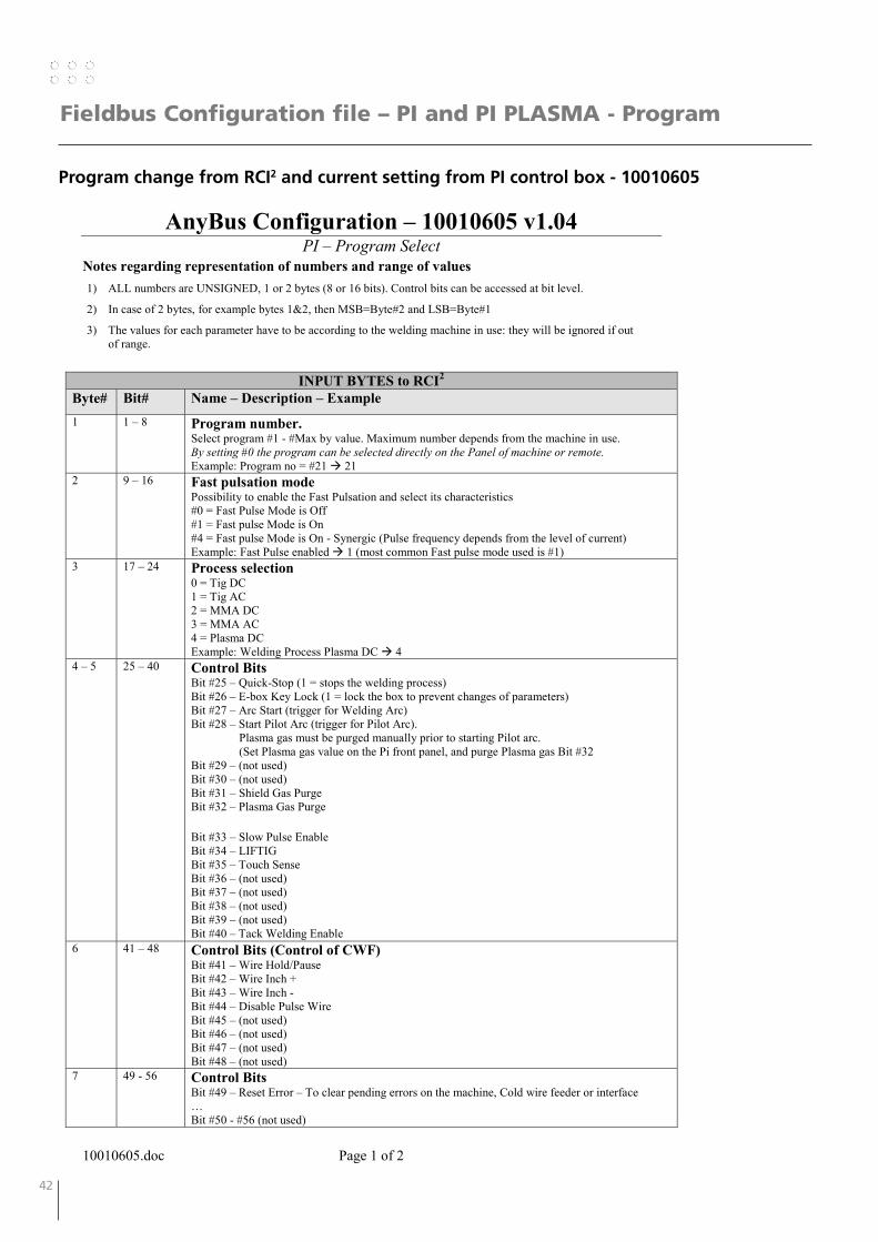
Notes regarding representation of numbers and range of values 1) ALL numbers are UNSIGNED, 1 or 2 bytes (8 or 16 bits). Control bits can be accessed at bit level.
2) In case of 2 bytes, for example bytes 1&2, then MSB=Byte#2 and LSB=Byte#1
3) The values for each parameter have to be according to the welding machine in use: they will be ignored if out of range.
INPUT BYTES to RCI2
Byte# Bit# Name – Description – Example1 1 – 8 Program number.
Select program #1 - #Max by value. Maximum number depends from the machine in use. By setting #0 the program can be selected directly on the Panel of machine or remote. Example: Program no = #21 21
2 9 – 16 Fast pulsation mode Possibility to enable the Fast Pulsation and select its characteristics #0 = Fast Pulse Mode is Off #1 = Fast pulse Mode is On #4 = Fast pulse Mode is On - Synergic (Pulse frequency depends from the level of current) Example: Fast Pulse enabled 1 (most common Fast pulse mode used is #1)
3 17 – 24 Process selection 0 = Tig DC 1 = Tig AC 2 = MMA DC 3 = MMA AC 4 = Plasma DC Example: Welding Process Plasma DC 4
4 – 5 25 – 40 Control Bits Bit #25 – Quick-Stop (1 = stops the welding process) Bit #26 – E-box Key Lock (1 = lock the box to prevent changes of parameters) Bit #27 – Arc Start (trigger for Welding Arc) Bit #28 – Start Pilot Arc (trigger for Pilot Arc). Plasma gas must be purged manually prior to starting Pilot arc. (Set Plasma gas value on the Pi front panel, and purge Plasma gas Bit #32 Bit #29 – (not used) Bit #30 – (not used) Bit #31 – Shield Gas Purge Bit #32 – Plasma Gas Purge
Bit #33 – Slow Pulse Enable Bit #34 – LIFTIG Bit #35 – Touch Sense Bit #36 – (not used) Bit #37 – (not used) Bit #38 – (not used) Bit #39 – (not used) Bit #40 – Tack Welding Enable
6 41 – 48 Control Bits (Control of CWF) Bit #41 – Wire Hold/Pause Bit #42 – Wire Inch + Bit #43 – Wire Inch - Bit #44 – Disable Pulse Wire Bit #45 – (not used) Bit #46 – (not used) Bit #47 – (not used) Bit #48 – (not used)
7 49 - 56 Control Bits Bit #49 – Reset Error – To clear pending errors on the machine, Cold wire feeder or interface … Bit #50 - #56 (not used)
42 43
Fieldbus Configuration file – PI and PI PLASMA - Program
Program change from RCI2 and current setting from PI control box - 10010605
AnyBus Configuration – 10010605 v1.04 PI – Program Select
10010605.doc Page 2 of 2
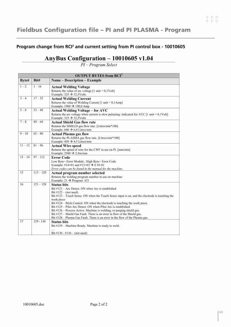
OUTPUT BYTES from RCI2
Byte# Bit# Name – Description – Example 1 – 2 1 – 16 Actual Welding Voltage
Returns the value of arc voltage [1 unit = 0,1Volt]Example: 325 32,5Volts
3 – 4 17 – 32 Actual Welding Current Returns the value of Welding Current [1 unit = 0,1Amp] Example: 1900 190,0 Amp
5 – 6 33 – 48 Actual Welding Voltage – for AVC Returns the arc voltage when current is slow pulsating: indicated for AVC [1 unit = 0,1Volt] Example: 325 32,5Volts
7 – 8 49 – 64 Actual Shield Gas flow rate Returns the SHIELD gas flow rate. [Litres/min*100] Example: 600 6,0 Litres/min
9 – 10 65 – 80 Actual Plasma gas flowReturns the PLASMA gas flow rate. [Litres/min*100] Example: 450 4,5 Litres/min
11 – 12 81 – 96 Actual Wire speed Returns the speed of wire for the CWF in use on Pi. [mm/min] Example: 2500 2,5m/min
13 – 14 97 – 112 Error Code Low Byte= Error Module ; High Byte= Error Code Example: #14=01 and #13=03 E 03-01 Error codes can be found in the manual for the machine
15 113 – 120 Actual program number selected Returns the welding program number in use on machine Example: 21 Program #21
16 121 – 128 Status bits Bit #121 – Arc Detect. ON when Arc is established Bit #122 – (not used) Bit #123 – Touch Sense. ON when the Touch Sense input is on, and the electrode is touching the work piece Bit #124 – Stick Control. ON when the electrode is touching the work piece. Bit #125 – Pilot Arc Detect. ON when Pilot Arc is established. Bit #126 – Process Active. Machine is welding, or purging shield gas. Bit #127 – Shield Gas Fault. There is an error in flow of the Shield gas. Bit #128 – Plasma Gas Fault. There is an error in the flow of the Plasma gas.
17 129 - 136 Status bits Bit #129 – Machine Ready. Machine is ready to weld.… Bit #130 - #136 – (not used)

44 45
Fieldbus Configuration file – PI and PI PLASMA - Standard
Program change and current setting from RCI2 - 10010606
AnyBus Configuration – 10010606 v1.04 PI – Standard
10010606.doc Page 1 of 3
Notes regarding representation of numbers and range of values 1) ALL numbers are UNSIGNED, 1 or 2 bytes (8 or 16 bits). Control bits can be accessed at bit level.
2) In case of 2 bytes, for example bytes 1&2, then MSB=Byte#2 and LSB=Byte#1
3) The values for each parameter have to be according to the welding machine in use: they will be ignored if out of range.
INPUT Bytes to RCI2
Byte# Bit# Name – Description – Example1 – 2 1 – 16 Welding Current
Set the welding current. [Ampere*10] Example 420A 4200
3 - 4 17 – 32 Wire speed Set the speed of wire for the CWF specified on selected welding program of PI. [mm/min] Example: 1,5 m/min 1500
5 – 6 33 – 48 Plasma Gas Flow Rate Set the PLASMA gas flow rate. [Litres/min*100] Example: 4,5 Litres/min 450
7 49 – 56 Programme number. Select program #1 - #Max by value. Maximum number depends from the machine in use. By setting #0 the program can be selected directly on the Panel of machine or remote. Example: Program no = #21 21
8 57 – 64 Fast pulsation mode Possibility to enable the Fast Pulsation and select its characteristics #0 = Fast Pulse Mode is Off #1 = Fast pulse Mode is On #4 = Fast pulse Mode is On - Synergic (Pulse frequency depends from the level of current) Example: Fast Pulse enabled 1 (most common Fast pulse mode used is #1)
9 65 – 72 Process selection 0 = Tig DC 1 = Tig AC 2 = MMA DC 3 = MMA AC 4 = Plasma DC Example: Welding Process Plasma DC 4
10 - 11 73 – 88 Control Bits Bit #73 – Quick-Stop (1 = stops the welding process) Bit #74 – E-box Key Lock (1 = lock the box to prevent changes of parameters) Bit #75 – Arc Start (trigger for Welding Arc) Bit #76 – Start Pilot Arc (trigger for Pilot Arc). Plasma gas must be purged manually prior to starting Pilot arc. (Set Plasma gas value in byte 5&6, and purge Plasma gas Bit #80 Bit #77 – (not used) Bit #78 – (not used) Bit #79 – Shield Gas Purge Bit #80 – Plasma Gas Purge
Bit #81 – Slow Pulse Enable Bit #82 – LIFTIG Bit #83 – Touch Sense Bit #84 – (not used) Bit #85 – (not used) Bit #86 – (not used) Bit #87 – (not used) Bit #88 – Tack Welding Enable
44 45
Fieldbus Configuration file – PI and PI PLASMA - Standard
Program change and current setting from RCI2 - 10010606
AnyBus Configuration – 10010606 v1.04 PI – Standard
10010606.doc Page 2 of 3
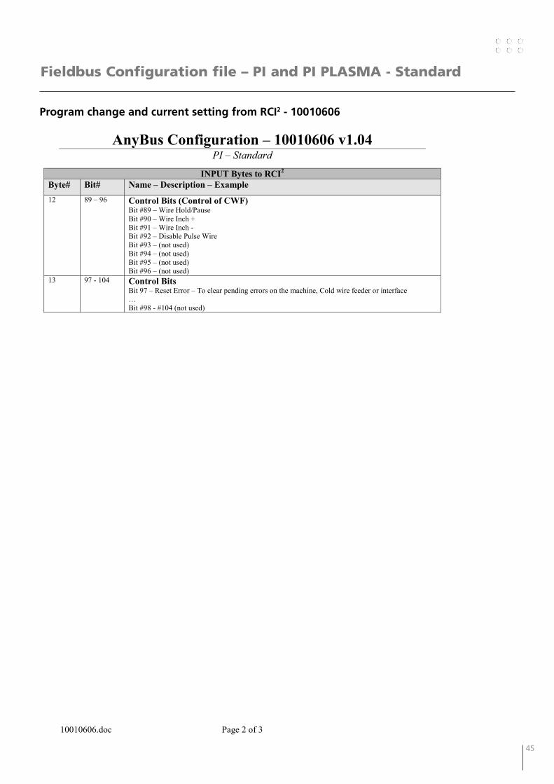
INPUT Bytes to RCI2
Byte# Bit# Name – Description – Example12 89 – 96 Control Bits (Control of CWF)
Bit #89 – Wire Hold/Pause Bit #90 – Wire Inch + Bit #91 – Wire Inch - Bit #92 – Disable Pulse Wire Bit #93 – (not used) Bit #94 – (not used) Bit #95 – (not used) Bit #96 – (not used)
13 97 - 104 Control Bits Bit 97 – Reset Error – To clear pending errors on the machine, Cold wire feeder or interface … Bit #98 - #104 (not used)
46 47
AnyBus Configuration – 10010606 v1.04 PI – Standard
10010606.doc Page 3 of 3
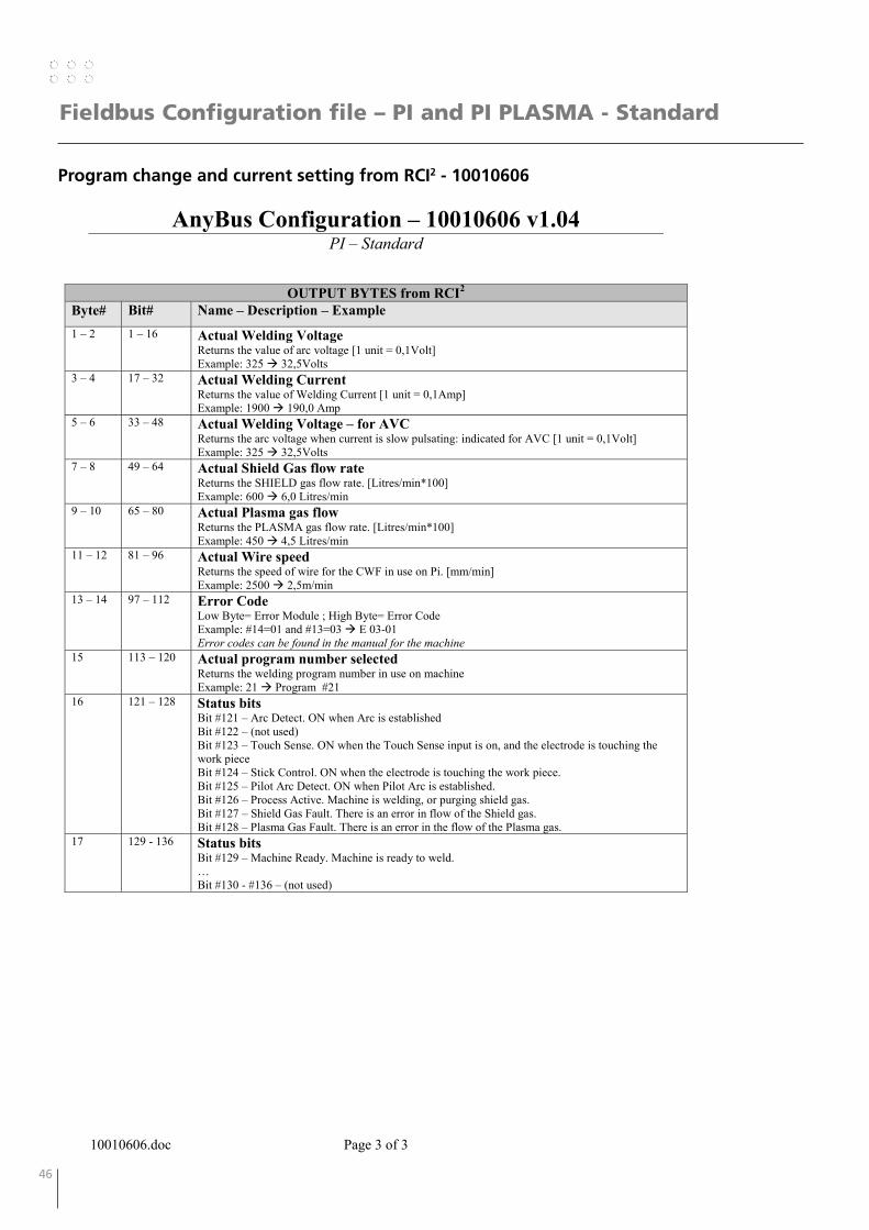
OUTPUT BYTES from RCI2
Byte# Bit# Name – Description – Example 1 – 2 1 – 16 Actual Welding Voltage
Returns the value of arc voltage [1 unit = 0,1Volt]Example: 325 32,5Volts
3 – 4 17 – 32 Actual Welding Current Returns the value of Welding Current [1 unit = 0,1Amp] Example: 1900 190,0 Amp
5 – 6 33 – 48 Actual Welding Voltage – for AVC Returns the arc voltage when current is slow pulsating: indicated for AVC [1 unit = 0,1Volt] Example: 325 32,5Volts
7 – 8 49 – 64 Actual Shield Gas flow rate Returns the SHIELD gas flow rate. [Litres/min*100] Example: 600 6,0 Litres/min
9 – 10 65 – 80 Actual Plasma gas flowReturns the PLASMA gas flow rate. [Litres/min*100] Example: 450 4,5 Litres/min
11 – 12 81 – 96 Actual Wire speed Returns the speed of wire for the CWF in use on Pi. [mm/min] Example: 2500 2,5m/min
13 – 14 97 – 112 Error Code Low Byte= Error Module ; High Byte= Error Code Example: #14=01 and #13=03 E 03-01 Error codes can be found in the manual for the machine
15 113 – 120 Actual program number selected Returns the welding program number in use on machine Example: 21 Program #21
16 121 – 128 Status bits Bit #121 – Arc Detect. ON when Arc is established Bit #122 – (not used) Bit #123 – Touch Sense. ON when the Touch Sense input is on, and the electrode is touching the work piece Bit #124 – Stick Control. ON when the electrode is touching the work piece. Bit #125 – Pilot Arc Detect. ON when Pilot Arc is established. Bit #126 – Process Active. Machine is welding, or purging shield gas. Bit #127 – Shield Gas Fault. There is an error in flow of the Shield gas. Bit #128 – Plasma Gas Fault. There is an error in the flow of the Plasma gas.
17 129 - 136 Status bits Bit #129 – Machine Ready. Machine is ready to weld.… Bit #130 - #136 – (not used)
Fieldbus Configuration file – PI and PI PLASMA - Standard
Program change and current setting from RCI2 - 10010606
46 47
Fieldbus Configuration file – PI and PI PLASMA - Std. for Motoman
Program change and current setting from RCI2 - 10010607
AnyBus Configuration – 10010607 v1.20 PI – Standard for Motoman
10010607.doc Page 1 of 3
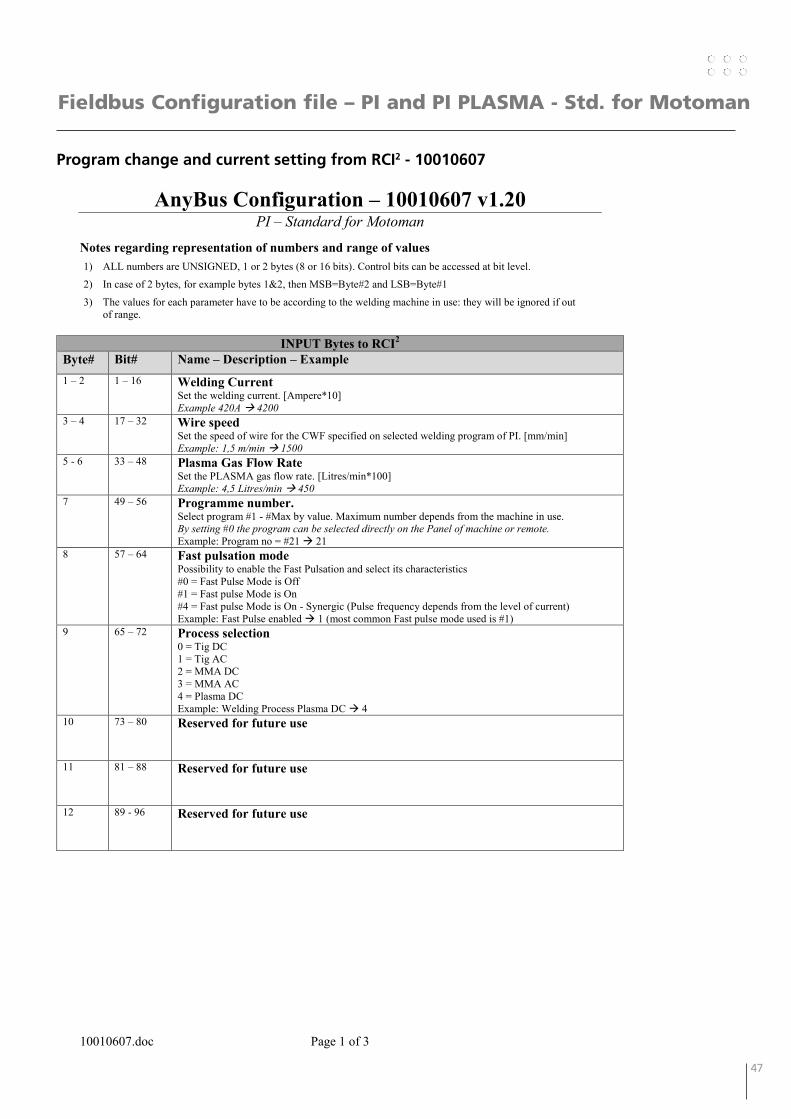
Notes regarding representation of numbers and range of values 1) ALL numbers are UNSIGNED, 1 or 2 bytes (8 or 16 bits). Control bits can be accessed at bit level.
2) In case of 2 bytes, for example bytes 1&2, then MSB=Byte#2 and LSB=Byte#1
3) The values for each parameter have to be according to the welding machine in use: they will be ignored if out of range.
INPUT Bytes to RCI2
Byte# Bit# Name – Description – Example 1 – 2 1 – 16 Welding Current
Set the welding current. [Ampere*10] Example 420A 4200
3 – 4 17 – 32 Wire speed Set the speed of wire for the CWF specified on selected welding program of PI. [mm/min] Example: 1,5 m/min 1500
5 - 6 33 – 48 Plasma Gas Flow Rate Set the PLASMA gas flow rate. [Litres/min*100] Example: 4,5 Litres/min 450
7 49 – 56 Programme number. Select program #1 - #Max by value. Maximum number depends from the machine in use. By setting #0 the program can be selected directly on the Panel of machine or remote. Example: Program no = #21 21
8 57 – 64 Fast pulsation mode Possibility to enable the Fast Pulsation and select its characteristics #0 = Fast Pulse Mode is Off #1 = Fast pulse Mode is On #4 = Fast pulse Mode is On - Synergic (Pulse frequency depends from the level of current) Example: Fast Pulse enabled 1 (most common Fast pulse mode used is #1)
9 65 – 72 Process selection 0 = Tig DC 1 = Tig AC 2 = MMA DC 3 = MMA AC 4 = Plasma DC Example: Welding Process Plasma DC 4
10 73 – 80 Reserved for future use
11 81 – 88 Reserved for future use
12 89 - 96 Reserved for future use
48 49
Fieldbus Configuration file – PI and PI PLASMA - Std. for Motoman
Program change and current setting from RCI2 - 10010607
AnyBus Configuration – 10010607 v1.20 PI – Standard for Motoman
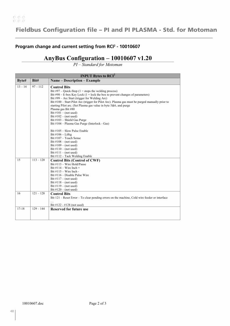
10010607.doc Page 2 of 3
INPUT Bytes to RCI2
Byte# Bit# Name – Description – Example 13 – 14 97 – 112 Control Bits
Bit #97 – Quick-Stop (1 = stops the welding process) Bit #98 – E-box Key Lock (1 = lock the box to prevent changes of parameters) Bit #99 – Arc Start (trigger for Welding Arc) Bit #100 – Start Pilot Arc (trigger for Pilot Arc). Plasma gas must be purged manually prior to starting Pilot arc. (Set Plasma gas value in byte 5&6, and purge Plasma gas Bit #80 Bit #101 – (not used) Bit #102 – (not used) Bit #103 – Shield Gas Purge Bit #104 – Plasma Gas Purge (Interlock - Gas) Bit #105 – Slow Pulse Enable Bit #106 – Liftig Bit #107 – Touch Sense Bit #108 – (not used) Bit #109 – (not used) Bit #110 – (not used) Bit #111 – (not used) Bit #112 – Tack Welding Enable
15 113 – 120 Control Bits (Control of CWF) Bit #113 – Wire Hold/Pause Bit #114 – Wire Inch + Bit #115 – Wire Inch - Bit #116 – Disable Pulse Wire Bit #117 – (not used) Bit #118 – (not used) Bit #119 – (not used) Bit #120 – (not used)
16 121 – 128 Control Bits Bit 121 – Reset Error – To clear pending errors on the machine, Cold wire feeder or interface … Bit #122 - #128 (not used)
17-18 129 – 144 Reserved for future use
48 49
Fieldbus Configuration file – PI and PI PLASMA - Std. for Motoman
Program change and current setting from RCI2 - 10010607
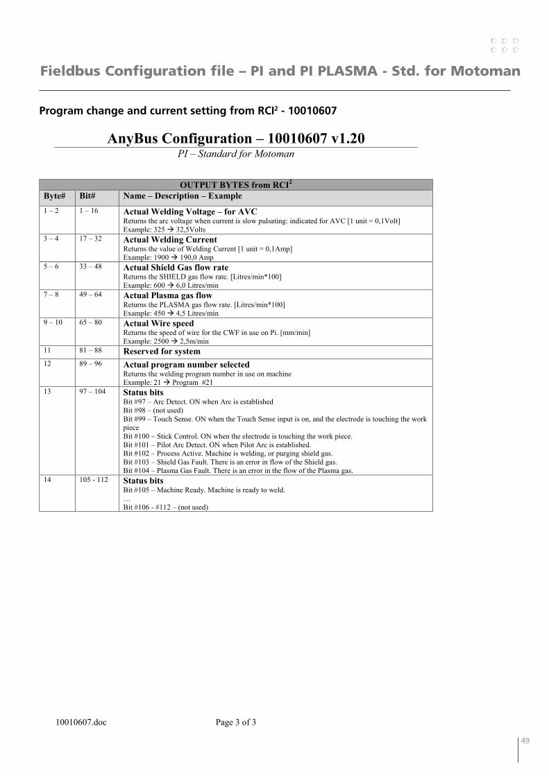
AnyBus Configuration – 10010607 v1.20 PI – Standard for Motoman
10010607.doc Page 3 of 3
OUTPUT BYTES from RCI2 Byte# Bit# Name – Description – Example 1 – 2 1 – 16 Actual Welding Voltage – for AVC
Returns the arc voltage when current is slow pulsating: indicated for AVC [1 unit = 0,1Volt] Example: 325 32,5Volts
3 – 4 17 – 32 Actual Welding Current Returns the value of Welding Current [1 unit = 0,1Amp] Example: 1900 190,0 Amp
5 – 6 33 – 48 Actual Shield Gas flow rate Returns the SHIELD gas flow rate. [Litres/min*100] Example: 600 6,0 Litres/min
7 – 8 49 – 64 Actual Plasma gas flow Returns the PLASMA gas flow rate. [Litres/min*100] Example: 450 4,5 Litres/min
9 – 10 65 – 80 Actual Wire speed Returns the speed of wire for the CWF in use on Pi. [mm/min] Example: 2500 2,5m/min
11 81 – 88 Reserved for system 12 89 – 96 Actual program number selected
Returns the welding program number in use on machine Example: 21 Program #21
13 97 – 104 Status bits Bit #97 – Arc Detect. ON when Arc is established Bit #98 – (not used) Bit #99 – Touch Sense. ON when the Touch Sense input is on, and the electrode is touching the work piece Bit #100 – Stick Control. ON when the electrode is touching the work piece. Bit #101 – Pilot Arc Detect. ON when Pilot Arc is established. Bit #102 – Process Active. Machine is welding, or purging shield gas. Bit #103 – Shield Gas Fault. There is an error in flow of the Shield gas. Bit #104 – Plasma Gas Fault. There is an error in the flow of the Plasma gas.
14 105 - 112 Status bits Bit #105 – Machine Ready. Machine is ready to weld. … Bit #106 - #112 – (not used)
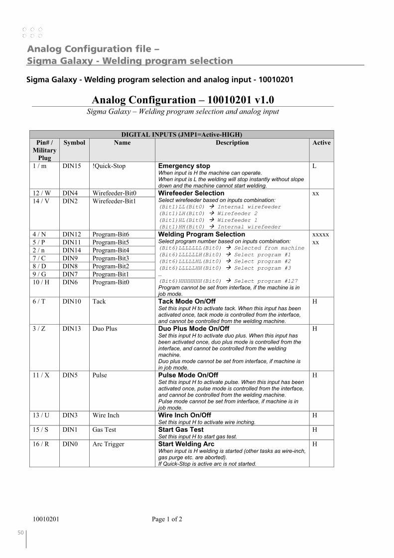
50 51
Analog Configuration file – Sigma Galaxy - Welding program selection
Sigma Galaxy - Welding program selection and analog input - 10010201
Analog Configuration – 10010201 v1.0 Sigma Galaxy – Welding program selection and analog input
10010201 Page 1 of 2
DIGITAL INPUTS (JMP1=Active-HIGH) Pin# /
Military Plug
Symbol Name Description Active
1 / m DIN15 !Quick-Stop Emergency stop When input is H the machine can operate. When input is L the welding will stop instantly without slope down and the machine cannot start welding.
L
12 / W DIN4 Wirefeeder-Bit0 Wirefeeder Selection Select wirefeeder based on inputs combination: (Bit1)LL(Bit0) Internal wirefeeder (Bit1)LH(Bit0) Wirefeeder 2 (Bit1)HL(Bit0) Wirefeeder 1 (Bit1)HH(Bit0) Internal wirefeeder
xx 14 / V DIN2 Wirefeeder-Bit1
4 / N DIN12 Program-Bit6 Welding Program Selection Select program number based on inputs combination: (Bit6)LLLLLLL(Bit0) Selected from machine (Bit6)LLLLLLH(Bit0) Select program #1 (Bit6)LLLLLHL(Bit0) Select program #2 (Bit6)LLLLLHH(Bit0) Select program #3 … (Bit6)HHHHHHH(Bit0) Select program #127 Program cannot be set from interface, if the machine is in job mode.
xxxxxxx 5 / P DIN11 Program-Bit5
2 / n DIN14 Program-Bit4 7 / C DIN9 Program-Bit3 8 / D DIN8 Program-Bit2 9 / G DIN7 Program-Bit1 10 / H DIN6 Program-Bit0
6 / T DIN10 Tack Tack Mode On/Off Set this input H to activate tack. When this input has been activated once, tack mode is controlled from the interface, and cannot be controlled from the welding machine.
H
3 / Z DIN13 Duo Plus Duo Plus Mode On/Off Set this input H to activate duo plus. When this input has been activated once, duo plus mode is controlled from the interface, and cannot be controlled from the welding machine. Duo plus mode cannot be set from interface, if machine is in job mode.
H
11 / X DIN5 Pulse Pulse Mode On/Off Set this input H to activate pulse. When this input has been activated once, pulse mode is controlled from the interface, and cannot be controlled from the welding machine. Pulse mode cannot be set from interface, if machine is in job mode.
H
13 / U DIN3 Wire Inch Wire Inch On/Off Set this input H to activate wire inching.
H
15 / S DIN1 Gas Test Start Gas Test Set this input H to start gas test.
H
16 / R DIN0 Arc Trigger Start Welding Arc When input is H welding is started (other tasks as wire-inch, gas purge etc. are aborted). If Quick-Stop is active arc is not started.
H
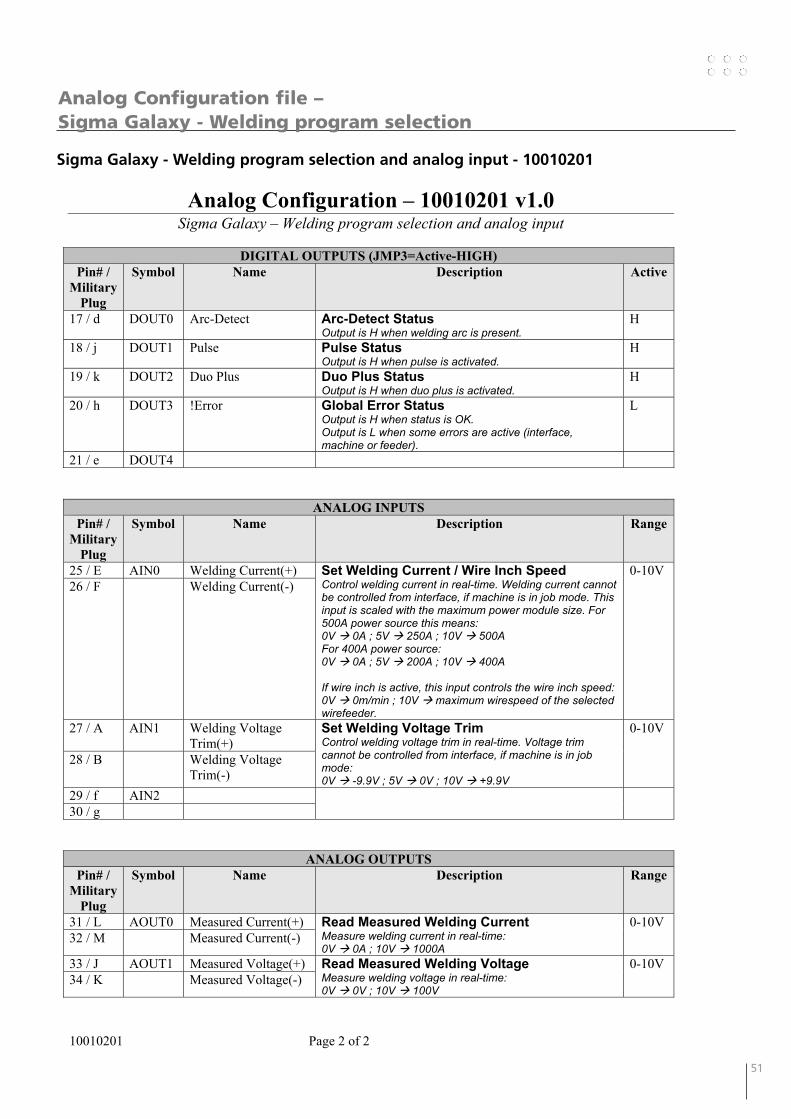
50 51
Sigma Galaxy - Welding program selection and analog input - 10010201
Analog Configuration file – Sigma Galaxy - Welding program selection
Analog Configuration – 10010201 v1.0 Sigma Galaxy – Welding program selection and analog input
10010201 Page 2 of 2
DIGITAL OUTPUTS (JMP3=Active-HIGH)
Pin# / Military
Plug
Symbol Name Description Active
17 / d DOUT0 Arc-Detect Arc-Detect Status Output is H when welding arc is present.
H
18 / j DOUT1 Pulse Pulse Status Output is H when pulse is activated.
H
19 / k DOUT2 Duo Plus Duo Plus Status Output is H when duo plus is activated.
H
20 / h DOUT3 !Error Global Error Status Output is H when status is OK. Output is L when some errors are active (interface, machine or feeder).
L
21 / e DOUT4
ANALOG INPUTS Pin# /
Military Plug
Symbol Name Description Range
25 / E AIN0 Welding Current(+) Set Welding Current / Wire Inch Speed Control welding current in real-time. Welding current cannot be controlled from interface, if machine is in job mode. This input is scaled with the maximum power module size. For 500A power source this means: 0V 0A ; 5V 250A ; 10V 500A For 400A power source: 0V 0A ; 5V 200A ; 10V 400A If wire inch is active, this input controls the wire inch speed: 0V 0m/min ; 10V maximum wirespeed of the selected wirefeeder.
0-10V 26 / F Welding Current(-)
27 / A AIN1 Welding Voltage Trim(+)
Set Welding Voltage Trim Control welding voltage trim in real-time. Voltage trim cannot be controlled from interface, if machine is in job mode: 0V -9.9V ; 5V 0V ; 10V +9.9V
0-10V
28 / B Welding Voltage Trim(-)
29 / f AIN2 30 / g
ANALOG OUTPUTS Pin# /
Military Plug
Symbol Name Description Range
31 / L AOUT0 Measured Current(+) Read Measured Welding Current Measure welding current in real-time: 0V 0A ; 10V 1000A
0-10V 32 / M Measured Current(-)
33 / J AOUT1 Measured Voltage(+) Read Measured Welding Voltage Measure welding voltage in real-time: 0V 0V ; 10V 100V
0-10V 34 / K Measured Voltage(-)

52 53
Sigma Galaxy – Sequence selection and analog input - 10010202
Analog Configuration file – Sigma Galaxy - Sequence selection
Analog Configuration – 10010202 v1.0 Sigma Galaxy – Sequence selection and analog input
10010202 Page 1 of 2
DIGITAL INPUTS (JMP1=Active-HIGH) Pin# /
Military Plug
Symbol Name Description Active
1 / m DIN15 !Quick-Stop Emergency stop When input is H the machine can operate. When input is L the welding will stop instantly without slope down and the machine cannot start welding.
L
12 / W DIN4 Wirefeeder-Bit0 Wirefeeder Selection Select wirefeeder based on inputs combination: (Bit1)LL(Bit0) Internal wirefeeder (Bit1)LH(Bit0) Wirefeeder 2 (Bit1)HL(Bit0) Wirefeeder 1 (Bit1)HH(Bit0) Internal wirefeeder
xx 14 / V DIN2 Wirefeeder-Bit1
4 / N DIN12 - Sequence Selection Select sequence number based on inputs combination: (Bit3)LLLL(Bit0) Normal (not sequence) mode (Bit3)LLLH(Bit0) Select sequence #1 (Bit3)LLHL(Bit0) Select sequence #2 (Bit3)LLHH(Bit0) Select sequence #3 … (Bit3)HLLH(Bit0) Select sequence #9 When this input has activated sequence mode, sequences are controlled from the interface, and cannot be controlled from the welding machine.
xxxx 5 / P DIN11 - 2 / n DIN14 - 7 / C DIN9 Sequence-Bit3 8 / D DIN8 Sequence-Bit2 9 / G DIN7 Sequence-Bit1 10 / H DIN6 Sequence-Bit0
6 / T DIN10 Tack Tack Mode On/Off Set this input H to activate tack. When this input has been activated once, tack mode is controlled from the interface, and cannot be controlled from the welding machine.
H
3 / Z DIN13 Duo Plus Duo Plus Mode On/Off Set this input H to activate duo plus. When this input has been activated once, duo plus mode is controlled from the interface, and cannot be controlled from the welding machine. Duo plus mode cannot be set from interface, if machine is in job mode.
H
11 / X DIN5 Pulse Pulse Mode On/Off Set this input H to activate pulse. When this input has been activated once, pulse mode is controlled from the interface, and cannot be controlled from the welding machine. Pulse mode cannot be set from interface, if machine is in job mode.
H
13 / U DIN3 Wire Inch Wire Inch On/Off Set this input H to activate wire inching.
H
15 / S DIN1 Gas Test Start Gas Test Set this input H to start gas test.
H
16 / R DIN0 Arc Trigger Start Welding Arc When input is H welding is started (other tasks as wire-inch, gas purge etc. are aborted). If Quick-Stop is active arc is not started.
H
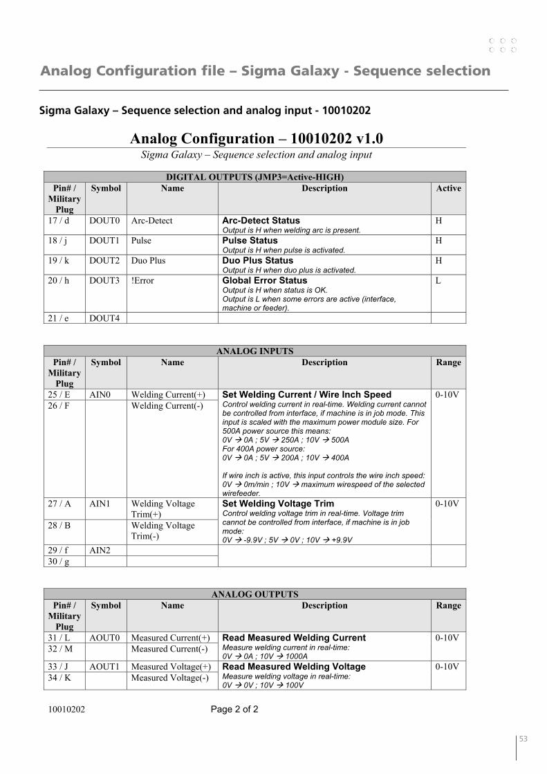
52 53
Analog Configuration file – Sigma Galaxy - Sequence selection
Sigma Galaxy – Sequence selection and analog input - 10010202
Analog Configuration – 10010202 v1.0 Sigma Galaxy – Sequence selection and analog input
10010202 Page 2 of 2
DIGITAL OUTPUTS (JMP3=Active-HIGH)
Pin# / Military
Plug
Symbol Name Description Active
17 / d DOUT0 Arc-Detect Arc-Detect Status Output is H when welding arc is present.
H
18 / j DOUT1 Pulse Pulse Status Output is H when pulse is activated.
H
19 / k DOUT2 Duo Plus Duo Plus Status Output is H when duo plus is activated.
H
20 / h DOUT3 !Error Global Error Status Output is H when status is OK. Output is L when some errors are active (interface, machine or feeder).
L
21 / e DOUT4
ANALOG INPUTS Pin# /
Military Plug
Symbol Name Description Range
25 / E AIN0 Welding Current(+) Set Welding Current / Wire Inch Speed Control welding current in real-time. Welding current cannot be controlled from interface, if machine is in job mode. This input is scaled with the maximum power module size. For 500A power source this means: 0V 0A ; 5V 250A ; 10V 500A For 400A power source: 0V 0A ; 5V 200A ; 10V 400A If wire inch is active, this input controls the wire inch speed: 0V 0m/min ; 10V maximum wirespeed of the selected wirefeeder.
0-10V 26 / F Welding Current(-)
27 / A AIN1 Welding Voltage Trim(+)
Set Welding Voltage Trim Control welding voltage trim in real-time. Voltage trim cannot be controlled from interface, if machine is in job mode: 0V -9.9V ; 5V 0V ; 10V +9.9V
0-10V
28 / B Welding Voltage Trim(-)
29 / f AIN2 30 / g
ANALOG OUTPUTS Pin# /
Military Plug
Symbol Name Description Range
31 / L AOUT0 Measured Current(+) Read Measured Welding Current Measure welding current in real-time: 0V 0A ; 10V 1000A
0-10V 32 / M Measured Current(-)
33 / J AOUT1 Measured Voltage(+) Read Measured Welding Voltage Measure welding voltage in real-time: 0V 0V ; 10V 100V
0-10V 34 / K Measured Voltage(-)
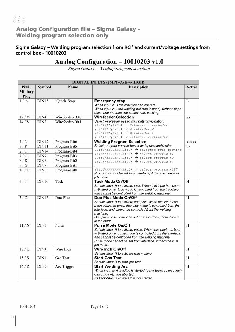
54 55
Analog Configuration file – Sigma Galaxy - Welding program selection only
Sigma Galaxy – Welding program selection from RCI2 and current/voltage settings from control box - 10010203
Analog Configuration – 10010203 v1.0 Sigma Galaxy – Welding program selection
10010203 Page 1 of 2
DIGITAL INPUTS (JMP1=Active-HIGH) Pin# /
Military Plug
Symbol Name Description Active
1 / m DIN15 !Quick-Stop Emergency stop When input is H the machine can operate. When input is L the welding will stop instantly without slope down and the machine cannot start welding.
L
12 / W DIN4 Wirefeeder-Bit0 Wirefeeder Selection Select wirefeeder based on inputs combination: (Bit1)LL(Bit0) Internal wirefeeder (Bit1)LH(Bit0) Wirefeeder 2 (Bit1)HL(Bit0) Wirefeeder 1 (Bit1)HH(Bit0) Internal wirefeeder
xx 14 / V DIN2 Wirefeeder-Bit1
4 / N DIN12 Program-Bit6 Welding Program Selection Select program number based on inputs combination: (Bit6)LLLLLLL(Bit0) Selected from machine (Bit6)LLLLLLH(Bit0) Select program #1 (Bit6)LLLLLHL(Bit0) Select program #2 (Bit6)LLLLLHH(Bit0) Select program #3 … (Bit6)HHHHHHH(Bit0) Select program #127 Program cannot be set from interface, if the machine is in job mode.
xxxxxxx 5 / P DIN11 Program-Bit5
2 / n DIN14 Program-Bit4 7 / C DIN9 Program-Bit3 8 / D DIN8 Program-Bit2 9 / G DIN7 Program-Bit1 10 / H DIN6 Program-Bit0
6 / T DIN10 Tack Tack Mode On/Off Set this input H to activate tack. When this input has been activated once, tack mode is controlled from the interface, and cannot be controlled from the welding machine.
H
3 / Z DIN13 Duo Plus Duo Plus Mode On/Off Set this input H to activate duo plus. When this input has been activated once, duo plus mode is controlled from the interface, and cannot be controlled from the welding machine. Duo plus mode cannot be set from interface, if machine is in job mode.
H
11 / X DIN5 Pulse Pulse Mode On/Off Set this input H to activate pulse. When this input has been activated once, pulse mode is controlled from the interface, and cannot be controlled from the welding machine. Pulse mode cannot be set from interface, if machine is in job mode.
H
13 / U DIN3 Wire Inch Wire Inch On/Off Set this input H to activate wire inching.
H
15 / S DIN1 Gas Test Start Gas Test Set this input H to start gas test.
H
16 / R DIN0 Arc Trigger Start Welding Arc When input is H welding is started (other tasks as wire-inch, gas purge etc. are aborted). If Quick-Stop is active arc is not started.
H

54 55
Analog Configuration file – Sigma Galaxy - Welding program selection only
Sigma Galaxy – Welding program selection from RCI2 and current/voltage settings from control box - 10010203
Analog Configuration file – Sigma Galaxy - Welding program selection only
Analog Configuration – 10010203 v1.0 Sigma Galaxy – Welding program selection
10010203 Page 2 of 2
DIGITAL OUTPUTS (JMP3=Active-HIGH)
Pin# / Military
Plug
Symbol Name Description Active
17 / d DOUT0 Arc-Detect Arc-Detect Status Output is H when welding arc is present.
H
18 / j DOUT1 Pulse Pulse Status Output is H when pulse is activated.
H
19 / k DOUT2 Duo Plus Duo Plus Status Output is H when duo plus is activated.
H
20 / h DOUT3 !Error Global Error Status Output is H when status is OK. Output is L when some errors are active (interface, machine or feeder).
L
21 / e DOUT4
ANALOG INPUTS Pin# /
Military Plug
Symbol Name Description Range
25 / E AIN0 26 / F 27 / A AIN1 28 / B 29 / f AIN2 30 / g
ANALOG OUTPUTS Pin# /
Military Plug
Symbol Name Description Range
31 / L AOUT0 Measured Current(+) Read Measured Welding Current Measure welding current in real-time: 0V 0A ; 10V 1000A
0-10V 32 / M Measured Current(-)
33 / J AOUT1 Measured Voltage(+) Read Measured Welding Voltage Measure welding voltage in real-time: 0V 0V ; 10V 100V
0-10V 34 / K Measured Voltage(-)
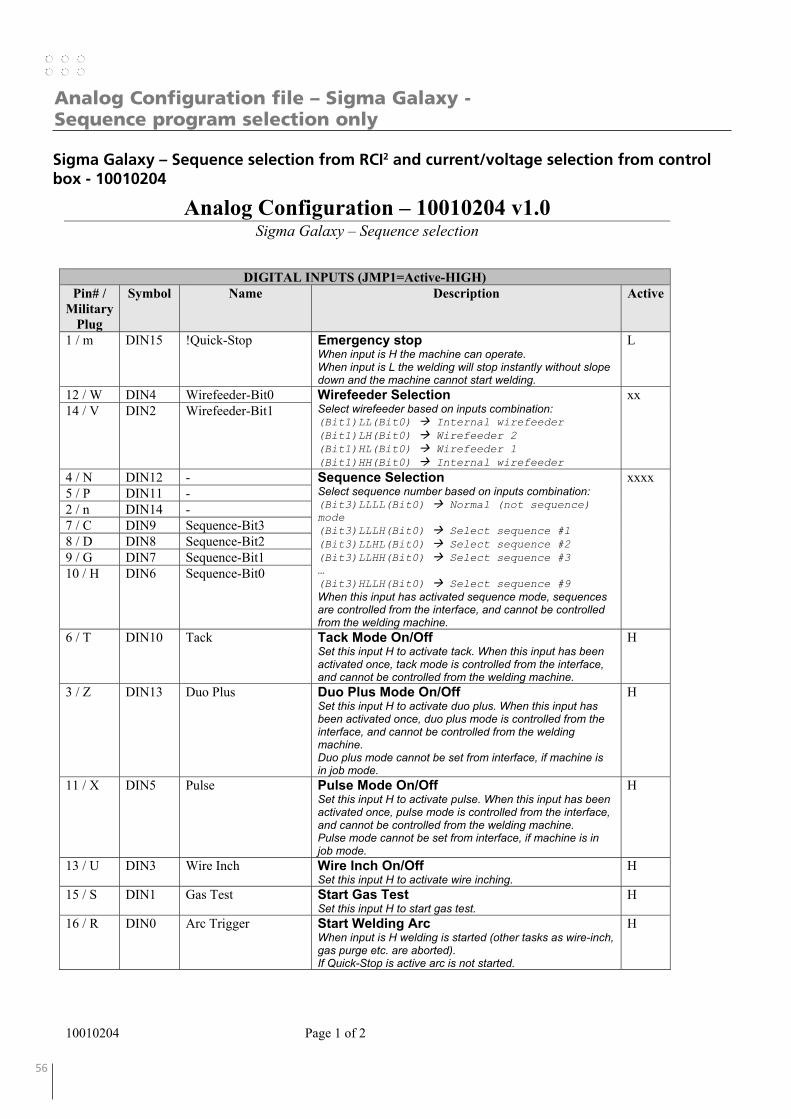
56 57
Analog Configuration file – Sigma Galaxy - Sequence program selection only
Sigma Galaxy – Sequence selection from RCI2 and current/voltage selection from control box - 10010204
Analog Configuration – 10010204 v1.0 Sigma Galaxy – Sequence selection
10010204 Page 1 of 2
DIGITAL INPUTS (JMP1=Active-HIGH) Pin# /
Military Plug
Symbol Name Description Active
1 / m DIN15 !Quick-Stop Emergency stop When input is H the machine can operate. When input is L the welding will stop instantly without slope down and the machine cannot start welding.
L
12 / W DIN4 Wirefeeder-Bit0 Wirefeeder Selection Select wirefeeder based on inputs combination: (Bit1)LL(Bit0) Internal wirefeeder (Bit1)LH(Bit0) Wirefeeder 2 (Bit1)HL(Bit0) Wirefeeder 1 (Bit1)HH(Bit0) Internal wirefeeder
xx 14 / V DIN2 Wirefeeder-Bit1
4 / N DIN12 - Sequence Selection Select sequence number based on inputs combination: (Bit3)LLLL(Bit0) Normal (not sequence) mode (Bit3)LLLH(Bit0) Select sequence #1 (Bit3)LLHL(Bit0) Select sequence #2 (Bit3)LLHH(Bit0) Select sequence #3 … (Bit3)HLLH(Bit0) Select sequence #9 When this input has activated sequence mode, sequences are controlled from the interface, and cannot be controlled from the welding machine.
xxxx 5 / P DIN11 - 2 / n DIN14 - 7 / C DIN9 Sequence-Bit3 8 / D DIN8 Sequence-Bit2 9 / G DIN7 Sequence-Bit1 10 / H DIN6 Sequence-Bit0
6 / T DIN10 Tack Tack Mode On/Off Set this input H to activate tack. When this input has been activated once, tack mode is controlled from the interface, and cannot be controlled from the welding machine.
H
3 / Z DIN13 Duo Plus Duo Plus Mode On/Off Set this input H to activate duo plus. When this input has been activated once, duo plus mode is controlled from the interface, and cannot be controlled from the welding machine. Duo plus mode cannot be set from interface, if machine is in job mode.
H
11 / X DIN5 Pulse Pulse Mode On/Off Set this input H to activate pulse. When this input has been activated once, pulse mode is controlled from the interface, and cannot be controlled from the welding machine. Pulse mode cannot be set from interface, if machine is in job mode.
H
13 / U DIN3 Wire Inch Wire Inch On/Off Set this input H to activate wire inching.
H
15 / S DIN1 Gas Test Start Gas Test Set this input H to start gas test.
H
16 / R DIN0 Arc Trigger Start Welding Arc When input is H welding is started (other tasks as wire-inch, gas purge etc. are aborted). If Quick-Stop is active arc is not started.
H
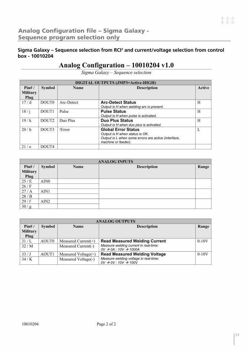
56 57
Sigma Galaxy – Sequence selection from RCI2 and current/voltage selection from control box - 10010204
Analog Configuration file – Sigma Galaxy - Sequence program selection only
Analog Configuration – 10010204 v1.0 Sigma Galaxy – Sequence selection
10010204 Page 2 of 2
DIGITAL OUTPUTS (JMP3=Active-HIGH)
Pin# / Military
Plug
Symbol Name Description Active
17 / d DOUT0 Arc-Detect Arc-Detect Status Output is H when welding arc is present.
H
18 / j DOUT1 Pulse Pulse Status Output is H when pulse is activated.
H
19 / k DOUT2 Duo Plus Duo Plus Status Output is H when duo plus is activated.
H
20 / h DOUT3 !Error Global Error Status Output is H when status is OK. Output is L when some errors are active (interface, machine or feeder).
L
21 / e DOUT4
ANALOG INPUTS Pin# /
Military Plug
Symbol Name Description Range
25 / E AIN0 26 / F 27 / A AIN1 28 / B 29 / f AIN2 30 / g
ANALOG OUTPUTS Pin# /
Military Plug
Symbol Name Description Range
31 / L AOUT0 Measured Current(+) Read Measured Welding Current Measure welding current in real-time: 0V 0A ; 10V 1000A
0-10V 32 / M Measured Current(-)
33 / J AOUT1 Measured Voltage(+) Read Measured Welding Voltage Measure welding voltage in real-time: 0V 0V ; 10V 100V
0-10V 34 / K Measured Voltage(-)
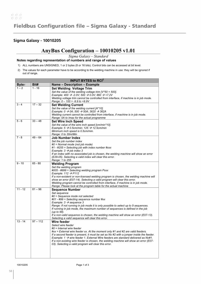
58 59
Fieldbus Configuration file – Sigma Galaxy - Standard
Sigma Galaxy - 10010205
AnyBus Configuration – 10010205 v1.01 Sigma Galaxy – Standard
10010205 Page 1 of 3
Notes regarding representation of numbers and range of values 1) ALL numbers are UNSIGNED, 1 or 2 bytes (8 or 16 bits). Control bits can be accessed at bit level.
2) The values for each parameter have to be according to the welding machine in use: they will be ignored if out of range.
INPUT BYTES to RCI2
Byte# Bit# Name – Description – Example 1 – 2 1 - 16 Set Welding Voltage Trim
Set the value of the welding voltage trim [V*50 + 500]. Example: 400 -2.0V; 500 0.0V; 860 +7.2V Welding voltage trim cannot be controlled from interface, if machine is in job mode. Range: 0 – 100 = -9.9 to +9.9V
3 - 4 17 – 32 Set Welding Current Set the value of the welding current [A*10]. Example: 0 0A; 500 50A; 3620 362A Welding current cannot be controlled from interface, if machine is in job mode. Range: 0A to Imax for the actual programme
5 - 6 33 – 48 Set Wire Inch Speed Set the value of the wire inch speed [cm/min*10]. Example: 5 0.5cm/min; 125 12.5cm/min Minimum inch speed is 0.5cm/min. Range: 0 to 30m/Min
7 - 8 49 – 64 Job Number Index Set the job number index #0 = Normal mode (not job mode) #1 - #255 = Selecting job with index number #xxx Example: 3 job index 3 If an index with no associated job is chosen, the welding machine will show an error (E29-05). Selecting a valid index will clear this error. Range: 1 to 255
9 - 10 65 - 80 Welding Program Set the welding program #005 - #999 = Selecting welding program Pxxx Example: 112 P112 If a non-existent or non-licensed welding program is chosen, the welding machine will show an error (E07-14). Selecting a valid program will clear this error. Welding program cannot be controlled from interface, if machine is in job mode. Range: Please look at the program table for the actual machine
11 - 12 81 – 96 Sequence Number Set sequence #0 = Sequence mode not selected #01 - #99 = Selecting sequence number #xx Example: 3 sequence 3 Range: If not running in job mode it is only possible to select up to 9 sequences. If running in job mode, the maximum number of sequences is defined in the job (up to 99). If a non-valid sequence is chosen, the welding machine will show an error (E07-13). Selecting a valid sequence will clear this error.
13 - 14
97 – 112 Wire feeder Select wire feeder #0 = Internal wire feeder #xx = External wire feeder xx. At the moment only #1 and #2 are valid feeders. If a second feeder is present, it must be set as No #2 with a jumper inside the feeder. Example: 1 wire feeder 1. External Wire feeders are standard delivered as No#1. If a non-existing wire feeder is chosen, the welding machine will show an error (E07-03). Selecting a valid program will clear this error.
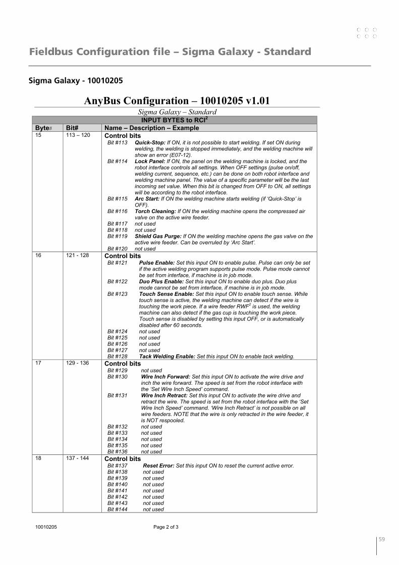
58 59
Fieldbus Configuration file – Sigma Galaxy - Standard
Sigma Galaxy - 10010205
AnyBus Configuration – 10010205 v1.01 Sigma Galaxy – Standard
10010205 Page 2 of 3
INPUT BYTES to RCI2 Byte# Bit# Name – Description – Example 15 113 – 120 Control bits
Bit #113 Quick-Stop: If ON, it is not possible to start welding. If set ON during welding, the welding is stopped immediately, and the welding machine will show an error (E07-12).
Bit #114 Lock Panel: If ON, the panel on the welding machine is locked, and the robot interface controls all settings. When OFF settings (pulse on/off, welding current, sequence, etc.) can be done on both robot interface and welding machine panel. The value of a specific parameter will be the last incoming set value. When this bit is changed from OFF to ON, all settings will be according to the robot interface.
Bit #115 Arc Start: If ON the welding machine starts welding (if ‘Quick-Stop’ is OFF).
Bit #116 Torch Cleaning: If ON the welding machine opens the compressed air valve on the active wire feeder.
Bit #117 not used Bit #118 not used Bit #119 Shield Gas Purge: If ON the welding machine opens the gas valve on the
active wire feeder. Can be overruled by ‘Arc Start’. Bit #120 not used
16 121 - 128 Control bits Bit #121 Pulse Enable: Set this input ON to enable pulse. Pulse can only be set
if the active welding program supports pulse mode. Pulse mode cannot be set from interface, if machine is in job mode.
Bit #122 Duo Plus Enable: Set this input ON to enable duo plus. Duo plus mode cannot be set from interface, if machine is in job mode.
Bit #123 Touch Sense Enable: Set this input ON to enable touch sense. While touch sense is active, the welding machine can detect if the wire is touching the work piece. If a wire feeder RWF2 is used, the welding machine can also detect if the gas cup is touching the work piece. Touch sense is disabled by setting this input OFF, or is automatically disabled after 60 seconds.
Bit #124 not used Bit #125 not used Bit #126 not used Bit #127 not used Bit #128 Tack Welding Enable: Set this input ON to enable tack welding.
17 129 - 136 Control bits Bit #129 not used Bit #130 Wire Inch Forward: Set this input ON to activate the wire drive and
inch the wire forward. The speed is set from the robot interface with the ‘Set Wire Inch Speed’ command.
Bit #131 Wire Inch Retract: Set this input ON to activate the wire drive and retract the wire. The speed is set from the robot interface with the ‘Set Wire Inch Speed’ command. ‘Wire Inch Retract’ is not possible on all wire feeders. NOTE that the wire is only retracted in the wire feeder, it is NOT respooled.
Bit #132 not used Bit #133 not used Bit #134 not used Bit #135 not used Bit #136 not used
18 137 - 144 Control bits Bit #137 Reset Error: Set this input ON to reset the current active error. Bit #138 not used Bit #139 not used Bit #140 not used Bit #141 not used Bit #142 not used Bit #143 not used Bit #144 not used

60 61
Fieldbus Configuration file – Sigma Galaxy - Standard
Sigma Galaxy - 10010205
AnyBus Configuration – 10010205 v1.01 Sigma Galaxy – Standard
10010205 Page 3 of 3
OUTPUT BYTES from RCI2
Byte# Bit# Name – Description – Example 1 - 2 1 - 16 Actual Welding Voltage
Returns the measured value of arc voltage [V*10]. Example: 325 32.5 V
3 – 4 17 – 32 Actual Welding Current Returns the measured value of welding current [A*10]. Example: 1900 190.0 Amp
5 – 6 33 – 48 Actual Gas Flow Returns the measured value of the gas flow [litres/min*10]. Example: 113 11.3 litres/min
7 – 8 49 – 64 Actual Wire Speed Returns the measured value of the wire speed [m/min*10]. Example: 62 6.2 m/min
9 – 10 65 – 80 Error Code Returns the error of the welding machine. Low Byte= Error Module ; High Byte= Error Code Example1: #9=00 and #10=00 E00-00 = No faults Example2: #9=01 and #10=04 E01-04 = Gas pressure too low Error codes can be found in the manual for the machine
11 – 12 81 - 96 Actual Job Index Returns the index of the job in use on the machine. Example1: 0 Machine running in normal mode, or the actual job has no index assigned Example2: 5 Job with index 5 is chosen Note: Job index must be set up at the Welding Machine before use
13 – 14 97 – 112 Actual Welding Program Number Returns the welding program number in use on machine. Example: 113 Program P113 is selected
15 – 16 113 – 128 Actual Sequence Number Returns the sequence number in use on machine. Example1: 0 Machine is not running in sequence mode Example2: 5 Sequence 5 is selected
17 – 18 129 – 144 Actual Wire Feeder Returns the active wire feeder in use on machine Example1: 0 Internal wire feeder is active Example2: 1 Wire feeder #1 is active
19 145 - 152 Status bits Bit #145 Arc Detect: Bit #146 not used Bit #147 Touch Sense: If touch sense is active this status reflects if the wire (or
for RWF² also the gas cup) has contact with the work piece. If status is ON there is contact.
Bit #148 Wire Stick: After each welding, wire stick detection is activated automatically. If the wire is sticking (touching the work piece) this output will be high. Wire stick will automatically disable, when the wire is not sticking anymore.
Bit #149 Pulse Enabled: Reflects the pulse mode status of the welding machine. Bit #150 Duo Plus Enabled: Reflects the duo plus mode status of the welding
machine. Bit #151 Gas Fault: If the welding machine has a gas fault, this status will be ON. Bit #152 Water Cooler: Reflects the status of the internal water cooler of the
welding machine. If ON the water cooler is running. Can be used to turn on an external water cooler.
20 153 - 160 Status bits Bit #153 Machine Ready: Reflects the status of the welding machine.
When ON the welding machine will be ready to weld. If the welding machine has an error, this status will be set to OFF.
Bit #154 - #160 not used
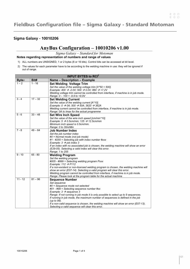
60 61
Fieldbus Configuration file – Sigma Galaxy - Standard Motoman
Sigma Galaxy - 10010206
AnyBus Configuration – 10010206 v1.00 Sigma Galaxy – Standard for Motoman
10010206 Page 1 of 4
Notes regarding representation of numbers and range of values 1) ALL numbers are UNSIGNED, 1 or 2 bytes (8 or 16 bits). Control bits can be accessed at bit level.
2) The values for each parameter have to be according to the welding machine in use: they will be ignored if out of range.
INPUT BYTES to RCI2
Byte# Bit# Name – Description – Example 1 – 2 1 - 16 Set Welding Voltage Trim
Set the value of the welding voltage trim [V*50 + 500]. Example: 400 -2.0V; 500 0.0V; 860 +7.2V Welding voltage trim cannot be controlled from interface, if machine is in job mode. Range: 0 – 100 = -9.9 to +9.9V
3 - 4 17 – 32 Set Welding Current Set the value of the welding current [A*10]. Example: 0 0A; 500 50A; 3620 362A Welding current cannot be controlled from interface, if machine is in job mode. Range: 0A to Imax for the actual programme
5 - 6 33 – 48 Set Wire Inch Speed Set the value of the wire inch speed [cm/min*10]. Example: 5 0.5cm/min; 125 12.5cm/min Minimum inch speed is 0.5cm/min. Range: 0 to 30m/Min
7 - 8 49 – 64 Job Number Index Set the job number index #0 = Normal mode (not job mode) #1 - #255 = Selecting job with index number #xxx Example: 3 job index 3 If an index with no associated job is chosen, the welding machine will show an error (E29-05). Selecting a valid index will clear this error. Range: 1 to 255
9 - 10 65 - 80 Welding Program Set the welding program #005 - #999 = Selecting welding program Pxxx Example: 112 P112 If a non-existent or non-licensed welding program is chosen, the welding machine will show an error (E07-14). Selecting a valid program will clear this error. Welding program cannot be controlled from interface, if machine is in job mode. Range: Please look at the program table for the actual machine
11 - 12 81 – 96 Sequence Number Set sequence #0 = Sequence mode not selected #01 - #99 = Selecting sequence number #xx Example: 3 sequence 3 Range: If not running in job mode it is only possible to select up to 9 sequences. If running in job mode, the maximum number of sequences is defined in the job (up to 99). If a non-valid sequence is chosen, the welding machine will show an error (E07-13). Selecting a valid sequence will clear this error.
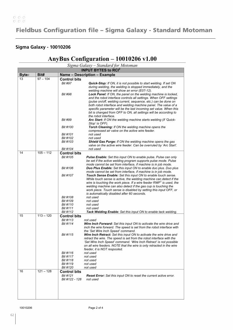
62 63
Fieldbus Configuration file – Sigma Galaxy - Standard Motoman
Sigma Galaxy - 10010206
AnyBus Configuration – 10010206 v1.00 Sigma Galaxy – Standard for Motoman
10010206 Page 2 of 4
INPUT BYTES to RCI2 Byte# Bit# Name – Description – Example 13 97 – 104 Control bits
Bit #97 Quick-Stop: If ON, it is not possible to start welding. If set ON during welding, the welding is stopped immediately, and the welding machine will show an error (E07-12).
Bit #98 Lock Panel: If ON, the panel on the welding machine is locked, and the robot interface controls all settings. When OFF settings (pulse on/off, welding current, sequence, etc.) can be done on both robot interface and welding machine panel. The value of a specific parameter will be the last incoming set value. When this bit is changed from OFF to ON, all settings will be according to the robot interface.
Bit #99 Arc Start: If ON the welding machine starts welding (if ‘Quick-Stop’ is OFF).
Bit #100 Torch Cleaning: If ON the welding machine opens the compressed air valve on the active wire feeder.
Bit #101 not used Bit #102 not used Bit #103 Shield Gas Purge: If ON the welding machine opens the gas
valve on the active wire feeder. Can be overruled by ‘Arc Start’. Bit #104 not used
14 105 – 112 Control bits Bit #105 Pulse Enable: Set this input ON to enable pulse. Pulse can only
be set if the active welding program supports pulse mode. Pulse mode cannot be set from interface, if machine is in job mode.
Bit #106 Duo Plus Enable: Set this input ON to enable duo plus. Duo plus mode cannot be set from interface, if machine is in job mode.
Bit #107 Touch Sense Enable: Set this input ON to enable touch sense. While touch sense is active, the welding machine can detect if the wire is touching the work piece. If a wire feeder RWF2 is used, the welding machine can also detect if the gas cup is touching the work piece. Touch sense is disabled by setting this input OFF, or is automatically disabled after 60 seconds.
Bit #108 not used Bit #109 not used Bit #110 not used Bit #111 not used Bit #112 Tack Welding Enable: Set this input ON to enable tack welding.
15 113 – 120 Control bits Bit #113 not used Bit #114 Wire Inch Forward: Set this input ON to activate the wire drive and
inch the wire forward. The speed is set from the robot interface with the ‘Set Wire Inch Speed’ command.
Bit #115 Wire Inch Retract: Set this input ON to activate the wire drive and retract the wire. The speed is set from the robot interface with the ‘Set Wire Inch Speed’ command. ‘Wire Inch Retract’ is not possible on all wire feeders. NOTE that the wire is only retracted in the wire feeder, it is NOT respooled.
Bit #116 not used Bit #117 not used Bit #118 not used Bit #119 not used Bit #120 not used
16 121 – 128 Control bits Bit #121 Reset Error: Set this input ON to reset the current active error. Bit #122 - 128 not used
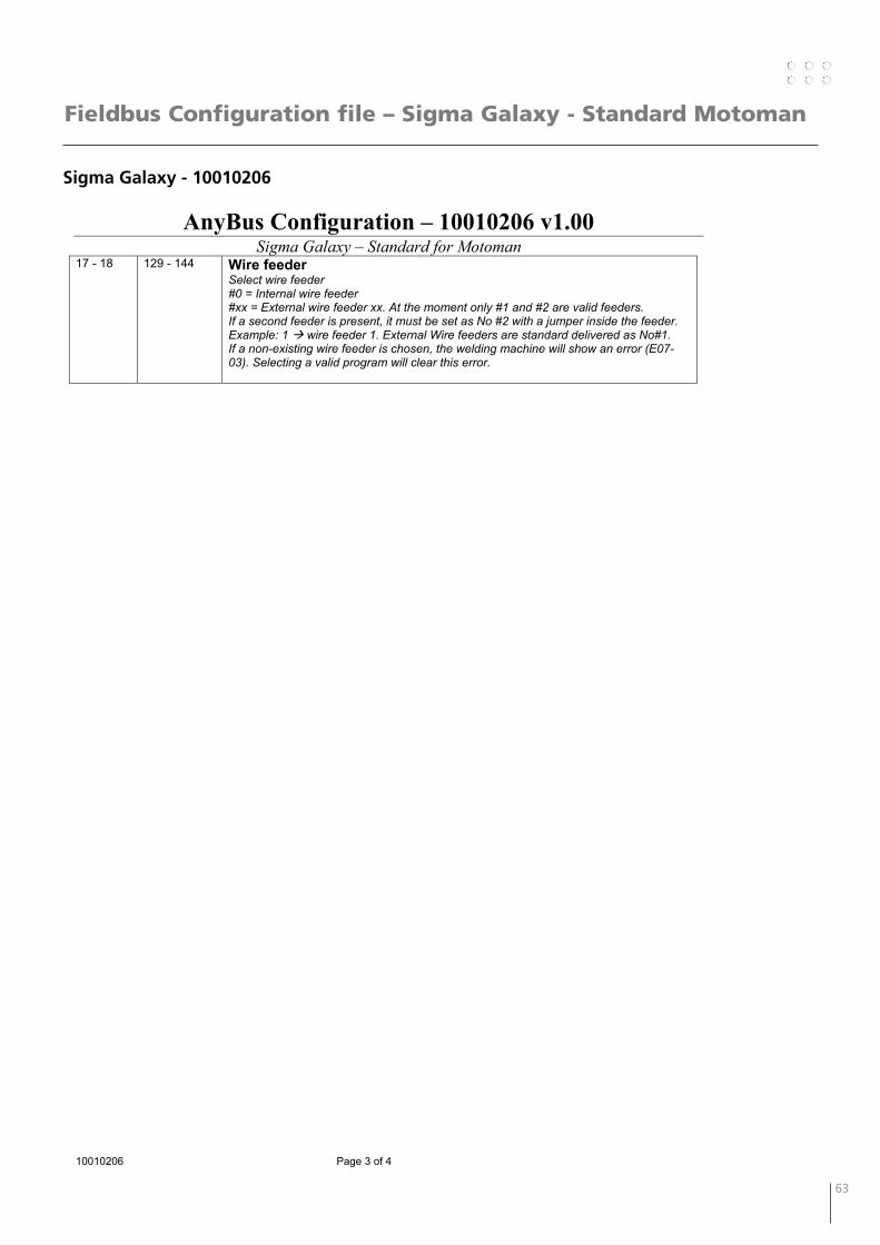
62 63
Fieldbus Configuration file – Sigma Galaxy - Standard Motoman
Sigma Galaxy - 10010206
AnyBus Configuration – 10010206 v1.00 Sigma Galaxy – Standard for Motoman
10010206 Page 3 of 4
17 - 18
129 - 144 Wire feeder Select wire feeder #0 = Internal wire feeder #xx = External wire feeder xx. At the moment only #1 and #2 are valid feeders. If a second feeder is present, it must be set as No #2 with a jumper inside the feeder. Example: 1 wire feeder 1. External Wire feeders are standard delivered as No#1. If a non-existing wire feeder is chosen, the welding machine will show an error (E07-03). Selecting a valid program will clear this error.
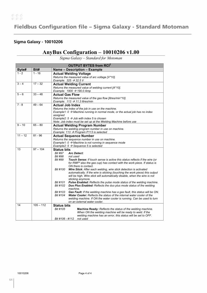
64 65
Fieldbus Configuration file – Sigma Galaxy - Standard Motoman
Sigma Galaxy - 10010206
AnyBus Configuration – 10010206 v1.00 Sigma Galaxy – Standard for Motoman
10010206 Page 4 of 4
OUTPUT BYTES from RCI2
Byte# Bit# Name – Description – Example 1 - 2 1 - 16 Actual Welding Voltage
Returns the measured value of arc voltage [V*10]. Example: 325 32.5 V
3 – 4 17 – 32 Actual Welding Current Returns the measured value of welding current [A*10]. Example: 1900 190.0 Amp
5 – 6 33 – 48 Actual Gas Flow Returns the measured value of the gas flow [litres/min*10]. Example: 113 11.3 litres/min
7 - 8 49 – 64 Actual Job Index Returns the index of the job in use on the machine. Example1: 0 Machine running in normal mode, or the actual job has no index assigned Example2: 5 Job with index 5 is chosen Note: Job index must be set up at the Welding Machine before use
9 – 10 65 – 80 Actual Welding Program Number Returns the welding program number in use on machine. Example: 113 Program P113 is selected
11 – 12 81 - 96 Actual Sequence Number Returns the sequence number in use on machine. Example1: 0 Machine is not running in sequence mode Example2: 5 Sequence 5 is selected
13 97 – 104 Status bits Bit #97 Arc Detect: Bit #98 not used Bit #99 Touch Sense: If touch sense is active this status reflects if the wire (or
for RWF² also the gas cup) has contact with the work piece. If status is ON there is contact.
Bit #100 Wire Stick: After each welding, wire stick detection is activated automatically. If the wire is sticking (touching the work piece) this output will be high. Wire stick will automatically disable, when the wire is not sticking anymore.
Bit #101 Pulse Enabled: Reflects the pulse mode status of the welding machine. Bit #102 Duo Plus Enabled: Reflects the duo plus mode status of the welding
machine. Bit #103 Gas Fault: If the welding machine has a gas fault, this status will be ON. Bit #104 Water Cooler: Reflects the status of the internal water cooler of the
welding machine. If ON the water cooler is running. Can be used to turn on an external water cooler.
14 105 – 112 Status bits Bit #105 Machine Ready: Reflects the status of the welding machine.
When ON the welding machine will be ready to weld. If the welding machine has an error, this status will be set to OFF.
Bit #106 - #112 not used
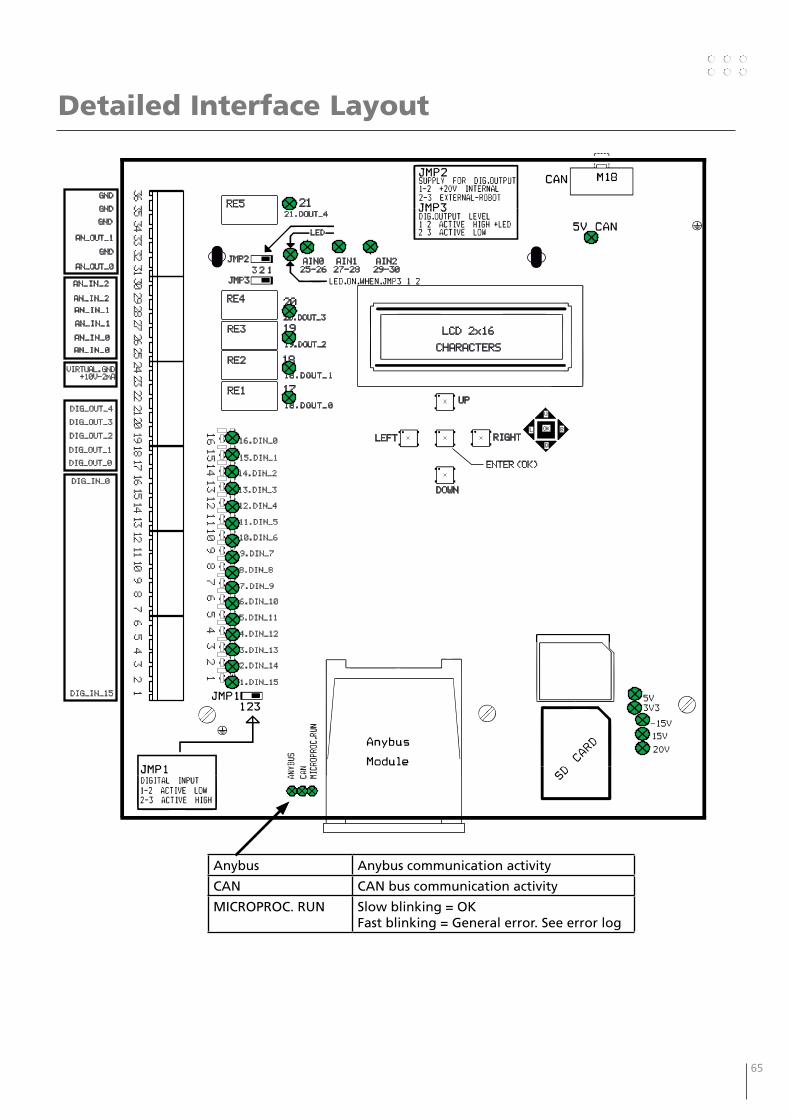
64 65
Detailed Interface Layout
161514131211109
87
65
43
21
DIG_IN_15
DIG_IN_0
10.DIN_6
6.DIN_10
5.DIN_11
8.DIN_8
4.DIN_12
7.DIN_9
1.DIN_15
3.DIN_13
14.DIN_2
15.DIN_1
13.DIN_3
11.DIN_5
12.DIN_4
9.DIN_7
2.DIN_14
16.DIN_0
161514131211109
87
65
43
21
23222120191817
27262524
31302928
35343332
36
DIG_OUT_0
DIG_OUT_1
DIG_OUT_2
DIG_OUT_4
DIG_OUT_3
VIRTUAL.GND
+10V-2mA
AN_IN_2
AN_IN_2
AN_IN_1
AN_IN_1
AN_IN_0
AN_IN_0
AN_OUT_0
GND
AN_OUT_1
GND
GND
GND
19.DOUT_2
20.DOUT_3
18.DOUT_1
21.DOUT_4
RE1
RE2
RE3
RE4
RE5
20
19
18
17
21
LEFT
LCD 2x16
CHARACTERS
UP
RIGHT
DOWN
ENTER (OK)
OK
U
L R
D
JMP2
JMP3
3 2 1
LED
AIN0
25-26
AIN1
27-28
AIN2
29-30
18.DOUT_0
Anybus Anybus communication activity
CAN CAN bus communication activity
MICROPROC. RUN Slow blinking = OKFast blinking = General error. See error log
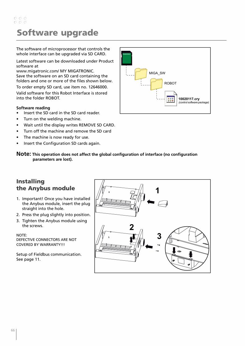
66 67
Software upgrade
The software of microprocessor that controls the whole interface can be upgraded via SD CARD.
Latest software can be downloaded under Product software at www.migatronic.com/ MY MIGATRONIC. Save the software on an SD card containing the folders and one or more of the files shown below.
To order empty SD card, use item no. 12646000.
Valid software for this Robot Interface is stored into the folder ROBOT.
Software reading• Insert the SD card in the SD card reader.
• Turn on the welding machine.
• Wait until the display writes REMOVE SD CARD.
• Turn off the machine and remove the SD card
• The machine is now ready for use.
• Insert the Configuration SD cards again.
Note: This operation does not affect the global configuration of interface (no configuration parameters are lost).
MIGA_SW
ROBOT
10020117.cry(control software package)
Installing the Anybus module
1. Important! Once you have installed the Anybus module, insert the plug straight into the hole.
2. Press the plug slightly into position.
3. Tighten the Anybus module using the screws.
NOTE:DEFECTIVE CONNECTORS ARE NOT COVERED BY WARRANTY!!!
Setup of Fieldbus communication. See page 11.
1
23

66 67
Troubleshooting
PROBLEM SOLUTIONThe welding current and voltage are instable It is strongly recommended to keep the digital filter
enabled, Analog Sens=Low. See Setup Menu – IOs Options.
LOW IMMUNITY, filter disabled, faster response to input changes – Analog Sens=High
HIGH IMMUNITY, filter enabled, slower response but higher immunity – Analog Sens=Low
The digital input are instable It is strongly recommended to keep the digital filter enabled, Digital Sens=Low. See Setup Menu – IOs Options
LOW IMMUNITY, filter disabled, faster response to input changes – Digital Sens=High
HIGH IMMUNITY, filter enabled, slower response but higher immunity – Digital Sens=Low
No functionality Check all supply and status LEDs.
5V_CAN. ON=OK OFF= 11V CAN supply coming from the
power source is missing. Check CAN cable
5 x supply LEDs OK=OK OFF= PCB 71617074 is defect.
Status LESs.
Network error Check all setups on RCI2Check all setups on robot/PLCCheck Anybus module
Device error This information is sent to RCI2, because there is a “legal” error on the welding machine or wire feeder.Like GAS or TEMP error or Emergency stop is activated. Check input LED 1.Correct the error on the welding machine or emergency stop.
Anybus Anybus communication activity
CAN CAN bus communication activity
MICROPROC. RUN Slow blinking = OKFast blinking = General error
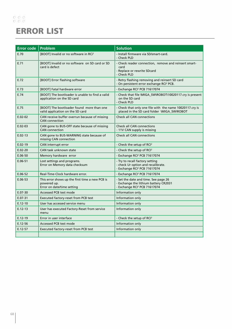
68 69
ERROR LIST
Error code Problem SolutionE.70 [BOOT] Invalid or no software in RCi2 - Install firmware via SD/smart-card.
- Check PLD
E.71 [BOOT] Invalid or no software on SD card or SD card is defect
- Check reader connection, remove and reinsert smart- card
- Replace or rewrite SDcard- Check PLD
E.72 [BOOT] Error flashing software - Retry flashing removing and reinsert SD card- On persistent error exchange RCI2 PCB.
E.73 [BOOT] Fatal hardware error - Exchange RCI2 PCB 71617074
E.74 [BOOT] The bootloader is unable to find a valid application on the SD card
- Check that file \MIGA_SW\ROBOT\10020117.cry is present on the SD card
- Check PLD
E.75 [BOOT] The bootloader found more than one valid application on the SD card
- Check that only one file with the name 10020117.cry is placed in the SD card folder \MIGA_SW\ROBOT
E.02-02 CAN receive buffer overrun because of missing CAN connection
Check all CAN connections
E.02-03 CAN gone to BUS-OFF state because of missing CAN connection
Check all CAN connections- 11V CAN supply is missing
E.02-13 CAN gone to BUS-WARNING state because of missing CAN connection
Check all CAN connections
E.02-19 CAN interrupt error - Check the setup of RCI2
E.02-20 CAN task unknown state - Check the setup of RCI2
E.06-50 Memory hardware error - Exchange RCI2 PCB 71617074
E.06-51 Lost settings and programs.Error on Memory data checksum
- Try to recall factory setting- check Ur option and recalibrate. - Exchange RCI2 PCB 71617074
E.06-52 Real-Time-Clock hardware error. - Exchange RCI2 PCB 71617074
E.06-53 This error shows up the first time a new PCB is powered up.Error on date/time setting
- Set the date and time. See page 26- Exchange the lithium battery CR2031- Exchange RCI2 PCB 71617074
E.07-30 Accessed PCB test mode Information only
E.07-31 Executed factory-reset from PCB test Information only
E.12-10 User has accessed service menu Information only
E.12-13 User has executed Factory-Reset from service menu
Information only
E.12-19 Error in user interface - Check the setup of RCI2
E.12-56 Accessed PCB test mode Information only
E.12-57 Executed factory-reset from PCB test Information only

68 69
ERROR LIST
Error code
Problem Solution
E.33-00 CAN MigaOpen - Device initialization timeout
- Error in configuration file- CAN bus error- Check CAN connection to welding machine
E.33-01 CAN MigaOpen - Device response error - CAN bus error- Check CAN connection to welding machine
E.33-02 CAN MigaOpen - Device watchdog One of the connected CAN controlled units has stopped sending Alive signal. Exchange the defective unit.- Check all connected units
E.33-03 CAN MigaOpen - Device status error This information is send to the Robot controller, because there is a “legal” error on the welding machine or wire feeder. Like GAS or TEMP error- Correct the error on the welding machine
E.33-04 CAN MigaOpen - Rule initialization timeout - Check the setup of RCI2
- Exchange RCI2 PCB 71617074
E.33-05 CAN MigaOpen - Network initialization timeout
Unable to connect to MIGANET,- Check CAN connection to welding machine and all connected devices
E.33-20 Analog I/O - Rule initialization error - Error in configuration file- Check/Reload configuration file- Check connected devices
E.33-21 Analog I/O - Error on received output message
- Error in configuration file- Check/Reload configuration file- Check connected devices
E.33-22 Analog I/O - Task unknown state - Check the setup of RCI2
E.33-40 Fieldbus- Anybus - module not present - A configuration file for an Anybus module is loaded in to RCI2 but the Anybus module is not mounted.
- Place the Anybus module in the socket
E.33-41 Fieldbus- Anybus - unsupported module type
- The installed software version does not support the mounted Anybus module
E.33-42 Fieldbus- Anybus - Driver information - Anybus module is defective. See also next pages “Anybus – Error list
E.33-43 Fieldbus- Anybus - Driver warning - Anybus module is defective. See also next pages “Anybus – Error list
E.33-44 Fieldbus- Anybus - Driver fatal error - Anybus module is defective. See also next pages “Anybus – Error list
E.33-45 Fieldbus- Anybus - Module communication timeout
- Anybus module is defective. See also next pages “Anybus – Error list
E.33-46 Fieldbus- Anybus - Network configuration error
- Anybus module is defective. See also next pages “Anybus – Error list
E.33-47 Fieldbus- Anybus - Process-data configuration error
- Anybus module is defective. See also next pages “Anybus – Error list
E.33-48 Fieldbus- Anybus - Activation error - Anybus module is defective. See also next pages “Anybus – Error list
E.33-49 Fieldbus- Anybus - Module error - There is at least one serious network error.- Check network cable- Check robot/PLC setup- Exchange the Anybus module if a restart is not solving the problem
See next page
E.33-50 Fieldbus- Anybus - Module exception - The Anybus module has ceased all network participation due to a host application-related error. This state is unrecoverable, i.e. the module must be restarted in order to be able to exchange network data.
- Exchange the Anybus module if a restart is not solving the problem See next page
E.33-51 Fieldbus- Anybus - Too many listen objects - Error in configuration file- Check/Reload configuration file
E.33-52 Fieldbus- Anybus - Task unknown state - Check the setup of RCI2
E.34-00 CAN MigaOpen Network Error - Check IDs settings of connected devices.
E.80-00 Class A trap - Check the setup of RCI2
E.80-01 Class B trap - Check the setup of RCI2
E.80-02 Vector trap - Check the setup of RCI2

70 71
ERROR LIST
Error code
Problem Solution
E.90-00 User has cleared logs - Information only
E.90-01 Invalid logs header - Clear the log.- If error continues then exchange the RCI2 PCB 71617074
E.90-02 Undefined error - Check the setup of RCI2
E.90-04 Too many active errors - Check the setup of RCI2
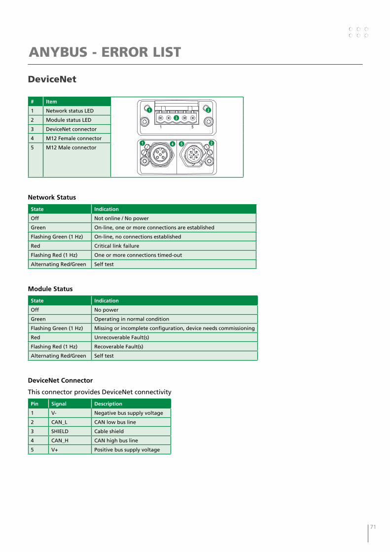
70 71
DeviceNet
# Item
1 Network status LED
2 Module status LED
3 DeviceNet connector
4 M12 Female connector
5 M12 Male connector
Network Status
State Indication
Off Not online / No power
Green On-line, one or more connections are established
Flashing Green (1 Hz) On-line, no connections established
Red Critical link failure
Flashing Red (1 Hz) One or more connections timed-out
Alternating Red/Green Self test
Module Status
State Indication
Off No power
Green Operating in normal condition
Flashing Green (1 Hz) Missing or incomplete configuration, device needs commissioning
Red Unrecoverable Fault(s)
Flashing Red (1 Hz) Recoverable Fault(s)
Alternating Red/Green Self test
DeviceNet Connector
This connector provides DeviceNet connectivity
Pin Signal Description
1 V- Negative bus supply voltage
2 CAN_L CAN low bus line
3 SHIELD Cable shield
4 CAN_H CAN high bus line
5 V+ Positive bus supply voltage
ANYBUS - ERROR LIST
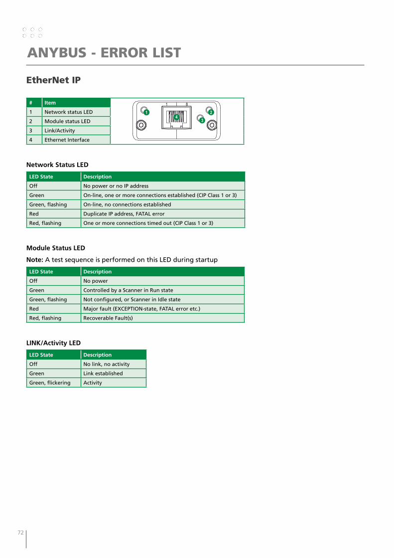
72 73
ANYBUS - ERROR LIST
EtherNet IP
# Item
1 Network status LED
2 Module status LED
3 Link/Activity
4 Ethernet Interface
Network Status LED
LED State Description
Off No power or no IP address
Green On-line, one or more connections established (CIP Class 1 or 3)
Green, flashing On-line, no connections established
Red Duplicate IP address, FATAL error
Red, flashing One or more connections timed out (CIP Class 1 or 3)
Module Status LED
Note: A test sequence is performed on this LED during startup
LED State Description
Off No power
Green Controlled by a Scanner in Run state
Green, flashing Not configured, or Scanner in Idle state
Red Major fault (EXCEPTION-state, FATAL error etc.)
Red, flashing Recoverable Fault(s)
LINK/Activity LED
LED State Description
Off No link, no activity
Green Link established
Green, flickering Activity
1 8
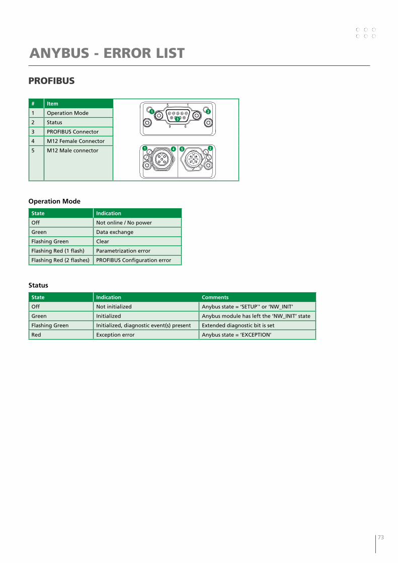
72 73
ANYBUS - ERROR LIST
PROFIBUS
# Item
1 Operation Mode
2 Status
3 PROFIBUS Connector
4 M12 Female Connector
5 M12 Male connector
Operation Mode
State Indication
Off Not online / No power
Green Data exchange
Flashing Green Clear
Flashing Red (1 flash) Parametrization error
Flashing Red (2 flashes) PROFIBUS Configuration error
Status
State Indication Comments
Off Not initialized Anybus state = ‘SETUP¨’ or ‘NW_INIT’
Green Initialized Anybus module has left the ‘NW_INIT’ state
Flashing Green Initialized, diagnostic event(s) present Extended diagnostic bit is set
Red Exception error Anybus state = ‘EXCEPTION’

74 75
ANYBUS - ERROR LIST
ProfiNet IP
# Item
1 Network status LED
2 Module status LED
3 Link/Activity LED
4 Ethernet Interface
Network Status LED
Note: A test sequence is performed on this LED during startup
LED State Description Comments
Off Offline - No power- No connection with IO Controller
Green Online (RUN) - Connection with IO Controller established- IO Controller in RUN state
Green, flashing Online (STOP) - Connection with IO Controller established- IO Controller in STOP state
Module Status LED
Note: A test sequence is performed on this LED during startup
LED State Description Comments
Off Not Initialized No power - or - Module in ‘SETUP’ or ‘NW_INIT’ state
Green Normal Operation Module has shifted from the ‘NW_INIT’ state
Green, 1 flash Diagnostic Event(s) Diagnostic event(s) present
Green, 2 flashes Blink Used by engineering tools to identify the node on the network
Red Exception Error Module in state ‘EXCEPTION’
Red, 1 flash Configuration Error Expected Identification differs from Real Identification
Red, 2 flashes IP Address Error IP address not set
Red, 3 flashes Station Name Error Station Name not set
Red, 4 flashes Internal Error Module has encountered a major internal error
LINK/Activity LED
LED State Description Comments
Off No link No link, no communication present
Green Link Ethernet link established, no communication present
Green, flickering Activity Ethernet link established, communication present
Ethernet InterfaceThe Ethernet interface operates at 100 Mbit, full duplex, with autonegotiation enabled as default.
1 8

74 75
ANYBUS - ERROR LIST
EtherCAT
Ethernet Connector
# Item
1 RUN LED
2 ERROR LED
3 EtherCAT (port 1)
4 EtherCAT (port 2)
5 Link/Activity (port 1)
6 Link/Activity (port 2)
RUN LED
This LED reflects the status of the CoE (CANopen over EtherCAT) communication
LED State Indication Description
Off INIT CoE device in ‘INIT’-state (or no power)
Green OPERATIONAL CoE device in ‘OPERATIONAL’-state
Green, blinking PRE-OPERATIONAL CoE device in ‘PRE-OPERATIONAL’-state
Green, single flash SAFE-OPERATIONAL CoE device in ‘SAFE-OPERATIONAL’-state
Reda (Fatal Event) -
a. If RUN and ERR turns red, this indicates a fatal event, forcing the bus interface to a physically passive state. Contact HMS technical support
ERR LED
This LED indicates EtherCAT communication errors etc.
LED State Indication Description
Off No error No error (or no power)
Red, blinking Invalid configuration State change received from master is not possible due to invalid register or object settings
Red, double flash Application watchdog timeout Sync manager watchdog timeout
Reda Application controller failure Anybus module in EXCEPTION
a. If RUN and ERR turns red, this indicates a fatal event, forcing the bus interface to a physically passive state. Contact HMS technical support
LINK/Activity
These LEDs indicate the EtherCAT link status and activity
LED State Indication Description
Off No link Link not sensed (or no power)
Green Link sensed, no activity Link sensed, no traffic detected
Green, flickering Link sensed, activity detected Link sensed, traffic detected
6

76 77
ELECTRIC DIAGRAM
11
22
HF
FILT
ER
RC
I
123456123456
11
22
123456123456123456123456
11
22
1 1 1 1 1 1 1 11
12
2
1
1
4 3 2
1
7 6 5
1
9 8
1 112 11 10
1
15 14 13
1
17 16
1
20 19 1823 22 21
1
11
22
25 24
1
28 27 26
11
31 30 2933 32
1
34
1 11
11
22
22
11
1212
1111
1010
99
44
33
55
88
77
66
AA
BB
CC
DD
1313
1414
A CDB
M?
CPC
AM
P 1
4 PO
L
11 1 1 11 1 1 1
11
22
1
123456
11
22
123456 123456
11
22
123456 123456 123456
DIG
ITAL
-IN
15
DIG
ITAL
-IN
14
DIG
ITAL
-IN
13
11
22
DIG
ITAL
-IN
12
DIG
ITAL
-IN
11
DIG
ITAL
-IN
10
11
22
DIG
ITAL
-IN
9
Mili
tary
Con
nect
orW
CR
W1
- 37
pole
s
DIG
ITAL
-IN
8
11
22
DIG
ITAL
-IN
7
DIG
ITAL
-IN
6
11
22
DIG
ITAL
-IN
5
DIG
ITAL
-IN
4
DIG
ITAL
-IN
3
DIG
ITAL
-IN
2
DIG
ITAL
-IN
1
GR
OUN
D
37s
DIG
ITAL
-IN
0
DIG
ITAL
-OU
T0D
IGIT
AL-O
UT1
DIG
ITAL
-OU
T2
2 15 4 37 610 9 8
DIG
ITAL
-OU
T3
13 12 11
+55V
15 1418 17 1621 20 1923 2226 25 2429 28 2731 3034 33 32
+11V
_CA
N
DIG
ITAL
-OU
T4
CA
N_H
I
RO
BOTS
UPP
LY_+
24V
+10V
_FLO
AT
GN
D_5
5VG
ND
_CA
N
GN
D_F
LOAT
CA
N_L
ANA
LOG
_IN
0AN
ALO
G_I
N1
22Z
ANA
LOG
_IN
2AN
ALO
G_I
N3
+55V
ANA
LOG
_IN
4AN
ALO
G_I
N5
ANA
LOG
_OU
T0
+11V
_CAN
GN
DAN
ALO
G_O
UT1
GN
D
CAN
_HI
13N
14P
17T
3C
4D
1
7G
2
GN
D_5
5V
8H
34
21X
5
20W
35
6
CA
N P
LUG
18U
36
7
19V
8
7161
0199
7161
7074
9
16S
10
GN
D_C
AN
15R
11
26d
1213
31j
14
32k
15
30h
16
11
22
17
27e
11
22
18
36r
CAN
_L
11
22
19
11
22
35p
2021
24b
11
22
22
5E
11
22
23
11
22
6F
24
11
22
1A
25
11
22
26
2B
11
22
27
11
22
28f
281
12
2
29g
291
12
2
30
11L
11
22
31
12M
11
22
321
12
2
9J
33
10K
34
12345678910
34n
33m
11
22
11
22
11
22
11
22
12345678910
11
22
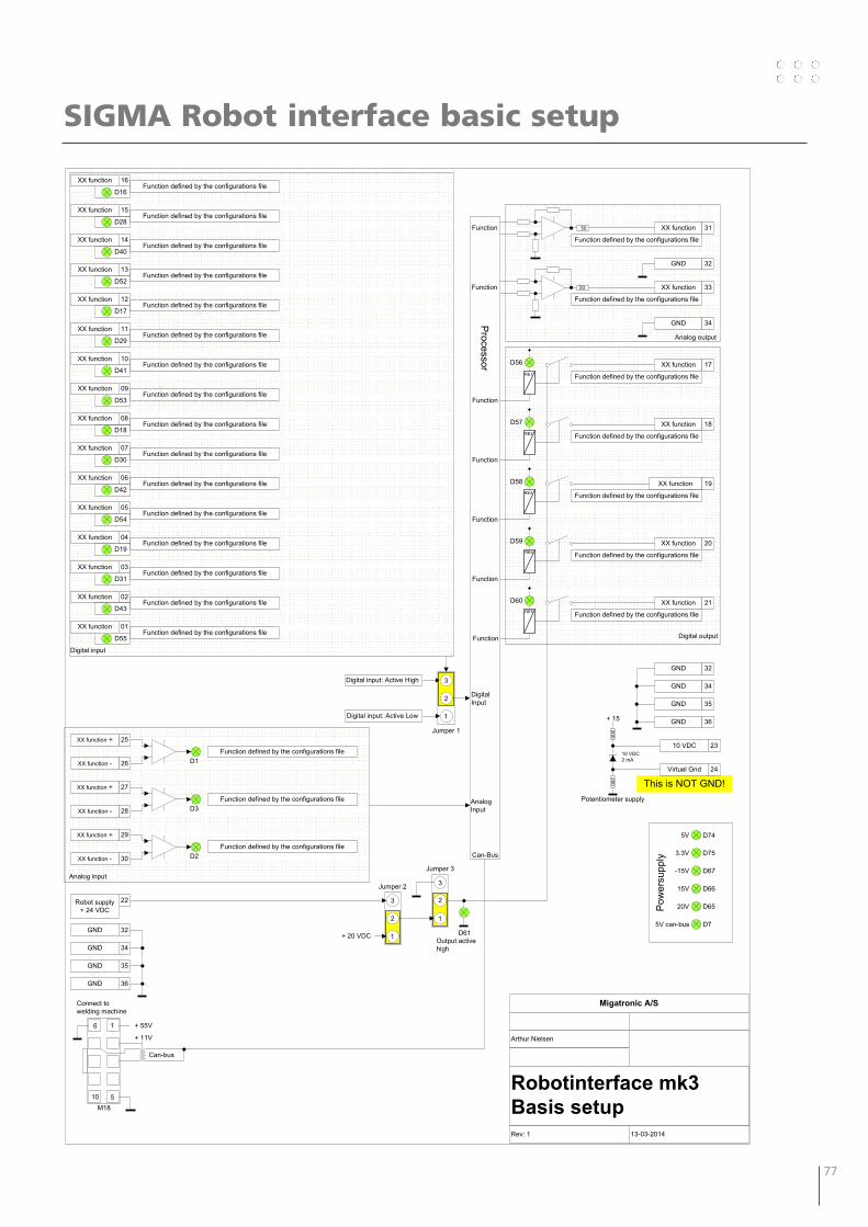
76 77
Migatronic A/S
Arthur Nielsen
Rev: 1 13-03-2014
Processor
15V
20V
3.3V
-15V
5V
Pow
ersu
pply
XX function 10
D41
XX function 09
D53
XX function 08
D18
XX function 07
D30
D42
XX function 06
XX function 03
XX function 11
XX function 16
XX function 13
XX function 15
XX function 01
D31
D29
D16
D52
D28
Digital input
AnalogInput
2
1
3
Jumper 1
Digital input: Active High
Digital input: Active Low
DigitalInput
Robot supply+ 24 VDC
22
2
1
3
Jumper 2
2
1
3
Jumper 3
GND 32
GND 34
D61Output activehigh
+
+
+
+
XX function 17
XX function 18
XX function 19
XX function 20
RE1
RE2
RE3
RE4
D56
D57
D58
D59
GND 32
GND 34
GND 32
GND 34
XX function 33
XX function 3150
50
D74
D75
D67
D66
D65
D7
D55
+ 20 VDC
Analog output
Digital output
1
5
6
10M18
+ 55V
+ 11V
Can-Bus
Connect to welding machine
Can-bus
GND 35
GND 36
5V can-bus
GND 35
GND 36
Function defined by the configurations file
Function defined by the configurations file
Function defined by the configurations file
Function defined by the configurations file
Function defined by the configurations file
Function defined by the configurations file
Function defined by the configurations file
Function defined by the configurations file
Function defined by the configurations file
Function defined by the configurations file
Function defined by the configurations file
XX function 02
D43Function defined by the configurations file
XX function 05
D54Function defined by the configurations file
XX function 04
D19Function defined by the configurations file
XX function 12
D17Function defined by the configurations file
XX function 14
D40Function defined by the configurations file
D1
25XX function +
26XX function -
Analog input
D3
27XX function +
28XX function -
D2
29XX function +
30XX function -
Function defined by the configurations file
Function defined by the configurations file
Function defined by the configurations file
Function
Function
Function
Function
Function
Function
Function defined by the configurations file
Function defined by the configurations file
+
XX function 21RE5
D60
Function defined by the configurations file
Function defined by the configurations file
Function defined by the configurations file
Function defined by the configurations file
Function defined by the configurations file
Function
+ 15
200200
10 VDC2 mA
Potentiometer supply
This is NOT GND!
10 VDC 23
Virtuel Gnd 24
SIGMA Robot interface basic setup

78 79
Reservedelsliste / Spare parts list / Ersatzteilliste / Liste des pièces de rechange
1
2
3
4
5
6
7
8
910
11
Pos. No. Varebetegnelse Description of goods Warenbezeichnung Désignation des pièces
78865026 Robot Control Interface RCI2 Robot Control Interface RCI2
Robot Control Interface RCI2 Robot Control Interface RCI2
1 24433719 Låg Cover Deckel Couvercle 2 70210693 Bundplade Sole plate Bodenplatte Plaque de fond 3 24510565 Afdækningsplade Cover plate Abdeckungsplatte Couvrir 4 74471227 Ledningssæt, CAN-filter stik Wire harness, CAN filter plug Leitungssatz, CAN-Filter Stecker Ensemble de filerie 5 74471349 Kabel med 37-polet stik Cable with 37-pole plug Kabel mit Stecker 37-polig Câble avec prise 37-pôle 6 24510563 Printplade PCB plate Printplatte Plaque de carte de circuits imprimé 7 71617074 Print CAN Interface PCB, CAN Interface Platine, CAN-Interface Carte de circuits imprimé, CAN-Interface 8 71610199 Print, RCI HF filter PCB, RCI HF filter Platine, RCI HF Filter Carte de circuits imprimé 9a 17200069 Anybus modul PROFIBUS Anybus module PROFIBUS Anybus Modul PROFIBUS Anybus module de PROFIBUS 9b 17200070 Anybus modul DEVICENET Anybus module DEVICENET Anybus Modul DEVICENET Anybus module de DEVICENET 9c 17200071 Anybus modul ETHERNET/IP Anybus module ETHERNET/IP Anybus Modul ETHERNET/IP Anybus module d’ETHERNET/IP 9d 17200072 Anybus modul PROFINET IO Anybus module PROFINET IO Anybus Modul PROFINET IO Anybus module de PROFINET IO 9e 17200073 Fieldbus modul EtherCAT Fieldbus module EtherCAT Fieldbus Modul EtherCAT Fieldbus module d’EtherCAT10 18190061 Stik, hun Plug 6 ways, female Stecker, weiblich Prise, femelle11 17280000 Lithium batteri, 3V ø20x3,2mm Lithium battery, 3V ø20x3,2mm Lithium Batterie, 3V ø20x3,2mm Battery au lithium , 3V ø20x3,2mm
78861376 Konfigurationskort Configuration Card Konfigurierungskarte Carte de configuration 74340015 Motorstyrings-/fjernreguleringskabel, 6m Motor control-/remote control cable, 6m Motorsteuerungs-/Fernregelungskabel, 6m Câble contrôle moteur/câble de commande, 6m 17210139 Multistik, 37-pol han for kabel Multiplug, 37-pole male for cable Vielfachstecker, 37-Polig männlich für Kabel Prise multibroche mâle, 37-pôle 18480039 Kabelaflastning for 37-polet stik Cable clamp for 37-pole plug Kabelschutz für Stecker 37-polig Verrou pour câble et prise 37 pôles

78 79

DENMARK:
Main officeSVEJSEMASKINEFABRIKKEN MIGATRONIC A/SAggersundvej 33, DK-9690 Fjerritslev, DenmarkTel. +45 96 500 600, www.migatronic.com
MIGATRONIC EUROPE:
Great BritainMIGATRONIC WELDING EQUIPMENT LTD21 Jubilee Drive, Belton Park, LoughboroughGB-Leicestershire LE11 5XS, Great BritainTel. +44 01509/267499, www.migatronic.co.uk
FranceMIGATRONIC EQUIPEMENT DE SOUDURE S.A.R.L. Parc Avenir II, 313 Rue Marcel Merieux FR-69530 Brignais, France Tel. +33 04 78 50 65 11, www.migatronic.fr
ItalyMIGATRONIC s.r.l. IMPIANTI PER SALDATURA Via Dei Quadri 40, IT-20871 Vimercate (MB), Italy Tel. +39 039 9278093, www.migatronic.it
NorwayMIGATRONIC NORGE AS Industriveien 6, N-3300 Hokksund, Norway Tel. +47 32 25 69 00, www.migatronic.no
Czech RepublicMIGATRONIC CZ a.s. Tolstého 451, CZ-415 03 Teplice 3, Czech Republic Tel. +420 411 135 600, www.migatronic.cz
HungaryMIGATRONIC KERESKEDELMI KFT. Szent Miklós u. 17/a, H-6000 Kecskemét, Hungary Tel. +36 76 505 969 www.migatronic.hu
MIGATRONIC ASIA:
ChinaSUZHOU MIGATRONIC WELDING TECHNOLOGY CO. LTD #4 FengHe Road, Industrial Park, CH-SuZhou, ChinaTel. +86 0512-87179800, www.migatronic.cn
MIGATRONIC AUTOMATION A/SKnøsgårdvej 112, DK-9440 Aabybro, DenmarkTel. +45 96 96 27 00, www.migatronic-automation.dk
FinlandMIGATRONIC OY PL 105, FI-04301 Tuusula, Finland Tel. +358 0102 176 500, www.migatronic.fi
HollandMIGATRONIC NEDERLAND B.V. Hallenweg 34, NL-5683 CT Best, Holland Tel. +31 499 37 50 00, www.migatronic.nl
SwedenMIGATRONIC SVETSMASKINER ABNääs Fabriker, Box 5015,S-448 50 Tollered, Sweden Tel. +46 031 44 00 45, www.migatronic.se
GermanyMIGATRONIC SCHWEISSMASCHINEN GMBH Sandusweg 12, D-35435 Wettenberg-Launsbach, Germany Tel. +49 0641/98284-0, www.migatronic.de
IndiaMIGATRONIC INDIA PRIVATE LTD.No.22 & 39/20H Sowri Street, IN-Alandur, Chennai – 600 016, IndiaTel. +91 44 2233 0074 www.migatronic.in