user guide hp power protector
TRANSCRIPT

HP Power Protector User Guide
Abstract This document includes installation, configuration, and operation information for HP Power Protector software. This document is for the person who installs and maintains power products. HP assumes you are qualified in the servicing of high-voltage equipment and trained in recognizing hazards in products with hazardous energy levels.
Part Number: 637916-002 A November 2012 Edition: 2

© Copyright 2011, 2012 Hewlett-Packard Development Company, L.P.
The information contained herein is subject to change without notice. The only warranties for HP products and services are set forth in the express warranty statements accompanying such products and services. Nothing herein should be construed as constituting an additional warranty. HP shall not be liable for technical or editorial errors or omissions contained herein.
Confidential computer software. Valid license from HP required for possession, use or copying. Consistent with FAR 12.211 and 12.212, Commercial Computer Software, Computer Software Documentation, and Technical Data for Commercial Items are licensed to the U.S. Government under vendor’s standard commercial license.
Microsoft®, Windows®, and Windows Server® are U.S. registered trademarks of Microsoft Corporation.
© 1998-2003 The OpenSSL Project. All rights reserved.
This product includes software developed by the OpenSSL Project for use in the OpenSSL Toolkit (http://www.openssl.org/).
Redistribution and use in source and binary forms, with or without modification, are permitted provided that the following conditions are met:
1 Redistributions of source code must retain the above copyright notice, this list of conditions and the following disclaimer. 2 Redistributions in binary form must reproduce the above copyright notice, this list of conditions and the following disclaimer in
the documentation and/or other materials provided with the distribution. 3 All advertising materials mentioning features or use of this software must display the following acknowledgment: "This product
includes software developed by the OpenSSL Project for use in the OpenSSL Toolkit. (http://www.openssl.org/)" 4 The names "OpenSSL Toolkit" and "OpenSSL Project" must not be used to endorse or promote products derived from this
software without prior written permission. For written permission, please contact [email protected]. 5 Products derived from this software may not be called "OpenSSL" nor may "OpenSSL" appear in their names without prior
written permission of the OpenSSL Project. 6 Redistributions of any form whatsoever must retain the following acknowledgment: "This product includes software developed by
the OpenSSL Project for use in the OpenSSL Toolkit (http://www.openssl.org/)." THIS SOFTWARE IS PROVIDED BY THE OpenSSL PROJECT "AS IS" AND ANY EXPRESSED OR IMPLIED WARRANTIES, INCLUDING, BUT NOT LIMITED TO, THE IMPLIED WARRANTIES OF MERCHANTABILITY AND FITNESS FOR A PARTICULAR PURPOSE ARE DISCLAIMED. IN NO EVENT SHALL THE OpenSSL PROJECT OR ITS CONTRIBUTORS BE LIABLE FOR ANY DIRECT, INDIRECT, INCIDENTAL, SPECIAL, EXEMPLARY, OR CONSEQUENTIAL DAMAGES (INCLUDING, BUT NOT LIMITED TO, PROCUREMENT OF SUBSTITUTE GOODS OR SERVICES; LOSS OF USE, DATA, OR PROFITS; OR BUSINESS INTERRUPTION) HOWEVER CAUSED AND ON ANY THEORY OF LIABILITY, WHETHER IN CONTRACT, STRICT LIABILITY, OR TORT (INCLUDING NEGLIGENCE OR OTHERWISE) ARISING IN ANY WAY OUT OF THE USE OF THIS SOFTWARE, EVEN IF ADVISED OF THE POSSIBILITY OF SUCH DAMAGE.
This product includes cryptographic software written by Eric Young ([email protected]). This product includes software written by Tim Hudson ([email protected]).
Original SSLeay License
© 1995-1998 Eric Young ([email protected])
All rights reserved.
This package is an SSL implementation written by Eric Young ([email protected]). The implementation was written so as to conform with Netscape SSL.
This library is free for commercial and non-commercial use as long as the following conditions are adhered to. The following conditions apply to all code found in this distribution, be it the RC4, RSA, lhash, DES, etc., code; not just the SSL code. The SSL documentation included with this distribution is covered by the same copyright terms except that the holder is Tim Hudson ([email protected]).
Copyright remains Eric Young's, and as such any Copyright notices in the code are not to be removed. If this package is used in a product, Eric Young should be given attribution as the author of the parts of the library used. This can be in the form of a textual message at program startup or in documentation (online or textual) provided with the package. Redistribution and use in source and binary forms, with or without modification, are permitted provided that the following conditions are met:

1 Redistributions of source code must retain the copyright notice, this list of conditions and the following disclaimer. 2 Redistributions in binary form must reproduce the above copyright notice, this list of conditions and the following disclaimer in
the documentation and/or other materials provided with the distribution. 3 All advertising materials mentioning features or use of this software must display the following acknowledgement: "This product
includes cryptographic software written by Eric Young ([email protected])." The word 'cryptographic' can be left out if the routines from the library being used are not cryptographic related.
4 If you include any Windows specific code (or a derivative thereof) from the apps directory (application code) you must include an acknowledgement: "This product includes software written by Tim Hudson ([email protected])."
THIS SOFTWARE IS PROVIDED BY ERIC YOUNG "AS IS" AND ANY EXPRESS OR IMPLIED WARRANTIES, INCLUDING, BUT NOT LIMITED TO, THE IMPLIED WARRANTIES OF MERCHANTABILITY AND FITNESS FOR A PARTICULAR PURPOSE ARE DISCLAIMED. IN NO EVENT SHALL THE AUTHOR OR CONTRIBUTORS BE LIABLE FOR ANY DIRECT, INDIRECT, INCIDENTAL, SPECIAL, EXEMPLARY, OR CONSEQUENTIAL DAMAGES (INCLUDING, BUT NOT LIMITED TO, PROCUREMENT OF SUBSTITUTE GOODS OR SERVICES; LOSS OF USE, DATA, OR PROFITS; OR BUSINESS INTERRUPTION) HOWEVER CAUSED AND ON ANY THEORY OF LIABILITY, WHETHER IN CONTRACT, STRICT LIABILITY, OR TORT (INCLUDING NEGLIGENCE OR OTHERWISE) ARISING IN ANY WAY OUT OF THE USE OF THIS SOFTWARE, EVEN IF ADVISED OF THE POSSIBILITY OF SUCH DAMAGE.
The license and distribution terms for any publicly available version or derivative of this code cannot be changed, i.e. this code cannot simply be copied and put under another distribution license (including the GNU Public License.)
©1999, 2000 Boris Fomitchev
This material is provided "as is," with absolutely no warranty expressed or implied. Any use is at your own risk. Permission to use or copy this software for any purpose is hereby granted without fee, provided the above notices are retained on all copies. Permission to modify the code and to distribute modified code is granted, provided the above notices are retained, and a notice that the code was modified is included with the above copyright notice. The Licensee may distribute binaries compiled with STLport (whether original or modified) without any royalties or restrictions. The Licensee may distribute original or modified STLport sources, provided that: the conditions indicated in the above permission notice are met, the following copyright notices are retained when present, and conditions provided in accompanying permission notices are met:
©1994 Hewlett-Packard Company
©1996, 97 Silicon Graphics Computer Systems, Inc.
©1997 Moscow Center for SPARC Technology
Permission to use, copy, modify, distribute and sell this software and its documentation for any purpose is hereby granted without fee, provided that the above copyright notice appear in all copies and that both that copyright notice and this permission notice appear in supporting documentation. Hewlett-Packard Company makes no representations about the suitability of this software for any purpose. It is provided "as is" without express or implied warranty. Permission to use, copy, modify, distribute and sell this software and its documentation for any purpose is hereby granted without fee, provided that the above copyright notice appear in all copies and that both that copyright notice and this permission notice appear in supporting documentation. Silicon Graphics makes no representations about the suitability of this software for any purpose. It is provided "as is" without express or implied warranty. Permission to use, copy, modify, distribute and sell this software and its documentation for any purpose is hereby granted without fee, provided that the above copyright notice appear in all copies and that both that copyright notice and this permission notice appear in supporting documentation. Moscow Center for SPARC Technology makes no representations about the suitability of this software for any purpose. It is provided "as is" without express or implied warranty.

Contents 4
Contents
Overview ..................................................................................................................................... 7 Introduction .............................................................................................................................................. 7 Overview ................................................................................................................................................. 7
Architecture .................................................................................................................................... 8 HPPP Administrator .......................................................................................................................... 9 HPPP Client ................................................................................................................................... 10 Supported hardware configurations ................................................................................................. 11 Setup overview ............................................................................................................................. 17
Installation ................................................................................................................................. 18 System requirements ................................................................................................................................ 18 Installation overview ................................................................................................................................ 18 Installing HPPP on Windows operating systems ........................................................................................... 19
Installing HPPP using the GUI installer on Windows systems ................................................................ 19 Installing HPPP using the silent installation method on Windows systems ............................................... 23 Uninstalling HPPP from Windows systems ......................................................................................... 23
Installing HPPP on Linux operating systems .................................................................................................. 23 Installing HPPP using the GUI installer on Linux systems ....................................................................... 23 Installing HPPP using the CLI on Linux systems .................................................................................... 26 Installing HPPP using the silent installation method on Linux systems ...................................................... 30 Uninstalling HPPP from Linux systems ................................................................................................ 32
Installing HPPP on HP-UX operating systems ................................................................................................ 33 Installing HPPP locally using the Generic Package method .................................................................. 33 Installing HPPP locally using the SAM method.................................................................................... 35 Installing HPPP remotely using the Generic Package method................................................................ 37 Installing HPPP remotely using the SAM method ................................................................................. 39 Installing HPPP using the silent installation method on HP-UX systems .................................................... 41 Uninstalling HPPP from HP-UX systems .............................................................................................. 43
Access and navigation ................................................................................................................ 44 Accessing the software ............................................................................................................................. 44
Web browser ............................................................................................................................... 44 Start menu .................................................................................................................................... 44 System tray icon ............................................................................................................................ 44
Notification window ................................................................................................................................ 45 Browser security alert ............................................................................................................................... 46
Establishing a secure session for Internet Explorer .............................................................................. 46 Establishing a secure session for Mozilla .......................................................................................... 47 Establishing a secure session for Firefox ........................................................................................... 47
Signing in .............................................................................................................................................. 48 Navigating the interface ........................................................................................................................... 48
Configuration and operation ........................................................................................................ 50 Settings .................................................................................................................................................. 50
Device Discovery screen ................................................................................................................. 50 Event Actions screen ...................................................................................................................... 54 Shutdown Parameters screen ........................................................................................................... 59

Contents 5
Scheduled Shutdown screen............................................................................................................ 63 System screen ............................................................................................................................... 66 User Accounts screen ..................................................................................................................... 68
Views .................................................................................................................................................... 69 Power Source screen ...................................................................................................................... 70 Reconfiguring an HPPP power source ............................................................................................... 79 Notified Applications screen ........................................................................................................... 86
Data logs ................................................................................................................................... 89 Logs ...................................................................................................................................................... 89
Events List screen ........................................................................................................................... 89 Events Calendar screen .................................................................................................................. 91 System Log screen ......................................................................................................................... 92
Troubleshooting .......................................................................................................................... 94 Cannot access HPPP after installation ......................................................................................................... 94 Cannot configure an HPPP Client power source ........................................................................................... 94 HPPP Clients do not appear on the HPPP Administrator Notified Application screen ......................................... 94 HPPP sends invalid links in email notifications on Linux platforms ................................................................... 94 Error occurs when starting the HPPP service on RHEL IA64 ............................................................................ 95 Invalid IP address .................................................................................................................................... 95 Links in emails do not work correctly for Linux ............................................................................................. 95 Low battery warning is displayed .............................................................................................................. 95 No power .............................................................................................................................................. 95 Notification window is not available on SLES 10 ......................................................................................... 96 On battery alarm .................................................................................................................................... 96 On boost alarm....................................................................................................................................... 96 On buck alarm ....................................................................................................................................... 96 Overload alarm ...................................................................................................................................... 96 Receiving a security error ......................................................................................................................... 96 Servers running Windows Server® 2003 do not restart ................................................................................ 96 Task Bar menu does not clear ................................................................................................................... 97 Unable to discover a UPS ......................................................................................................................... 97 UPS is not detected in RHEL5 when attached to serial ports other than COM 1 ................................................ 97 Utility alarm ............................................................................................................................................ 97
Alert messages ........................................................................................................................... 98 UPS alarms ............................................................................................................................................. 98
Security considerations .............................................................................................................. 102 Security considerations overview ............................................................................................................. 102
Firewall configuration ................................................................................................................ 103 Configuring the firewall on Windows operating systems ............................................................................. 103
Installing on a virtual operating system ........................................................................................ 113 Installing HPPP on Microsoft Hyper-V architecture ...................................................................................... 113
Configuring Microsoft Hyper-V Manager / Hyper-V Server R1/R2 ..................................................... 113 Hardware architecture ................................................................................................................. 116 Network architecture .................................................................................................................... 116 Installing HPPP on Hyper-V Server R1/R2 and Windows Server 2008 R2 (Hyper-V Manager) ............... 117 Alarm reception .......................................................................................................................... 117 Using HPPP with Hyper-V Server R1/R2 or Hyper-V Manager ........................................................... 117 Uninstalling HPPP ........................................................................................................................ 118
Installing HPPP on VMWare ESX architecture ............................................................................................ 118

Contents 6
Configuring VMware ESX Server 4.0 ............................................................................................. 119 Hardware architecture ................................................................................................................. 120 Network architecture .................................................................................................................... 120 Installing HPPP on VMware ESX Server 4.0 ..................................................................................... 120 Using HPPP with VMware ESX Server 4.0 ....................................................................................... 121
Installing HPPP on VMware ESXi architecture ............................................................................................ 122 Prerequisites ............................................................................................................................... 122 Installing VIMA/vMA on ESXi host machines ................................................................................... 123 Configuring VMware ESXi Server .................................................................................................. 123 Hardware architecture ................................................................................................................. 125 Network architecture .................................................................................................................... 125 Installing HPPP on VMware ESXi Server 5.X .................................................................................... 126 Using HPPP with VMware ESXi Server 5.X ...................................................................................... 126
Acronyms and abbreviations ...................................................................................................... 128
Documentation feedback ........................................................................................................... 130
Index ....................................................................................................................................... 131

Overview 7
Overview
Introduction HP Power Protector (HPPP) enables you to monitor, manage, and control power environments through comprehensive control of individual HP UPSs. A familiar browser interface provides secure access to HPPP anywhere on the network. You can control power failure settings to allow for maximum uptime of critical servers.
For a detailed list of supported UPSs, see the Supported Hardware matrix on the HP website (http://www.hp.com/go/rackandpower).
The software can run as a stand-alone power management system. This flexibility enables you to monitor, manage, and communicate with a UPS through a USB port, serial port, or an installed HP UPS Network Module. To facilitate day-to-day maintenance tasks, the software provides detailed system logs and system diagnostics, including UPS battery checks.
The HPPP package contains both the Administrator and Client components. The HPPP Administrator monitors the UPS status and notifies Clients of power related events, and communicates directly with the UPS through a USB or serial port. The HPPP Client gracefully shuts down protected servers in the event of a power failure, and communicates with the HPPP Administrator or HP UPS Network module through a network connection.
Use HPPP to:
• Customize alerts
o Send email notification messages.
o Issue computer commands at power failure.
• Monitor, manager, and control UPSs
o Manage a graceful shutdown of attached equipment during utility power failure.
o Prioritize the timing of equipment shutdown and reboot connected equipment by load segment.
o Delay restart by load segment after a power outage to sequence the startup of system components.
o Display text logs and graphical logs for analysis.
o Monitor the status of UPSs and perform diagnostics.
o Communicate with a UPS through a USB port, serial port, or an installed UPS Network Module.
Overview HPPP is a web-based application that enables administrators to manage an HP UPS from a browser-based management console. Administrators can monitor, manage, and control a single UPS locally and remotely.
During a utility power failure, the UPS switches to battery mode. An email alert can be issued to the system administrator, and a prioritized system shutdown begins based on user-defined settings for that specific UPS.
The UPS can be configured to extend runtimes for critical devices during utility power failures. For most UPSs, the receptacles on the rear panel can be divided into two or more groups, called load segments, which can

Overview 8
be controlled independently. By shutting down a load segment that is connected to less critical equipment, the runtime for more critical equipment is extended, providing additional protection.
Architecture The architecture consists of two major components:
• HPPP Administrator or HP UPS Network Module
• HPPP Client
The following image shows the HPPP Administrator architecture:
Item Description
1 HPPP Administrator
2 A UPS that is connected to the HPPP Administrator through a serial port or USB port
3 HPPP Client server
4 Network
5 A remote workstation browsing into the HPPP Administrator over the network
Green Power connection
Red Communication path
Overview 9
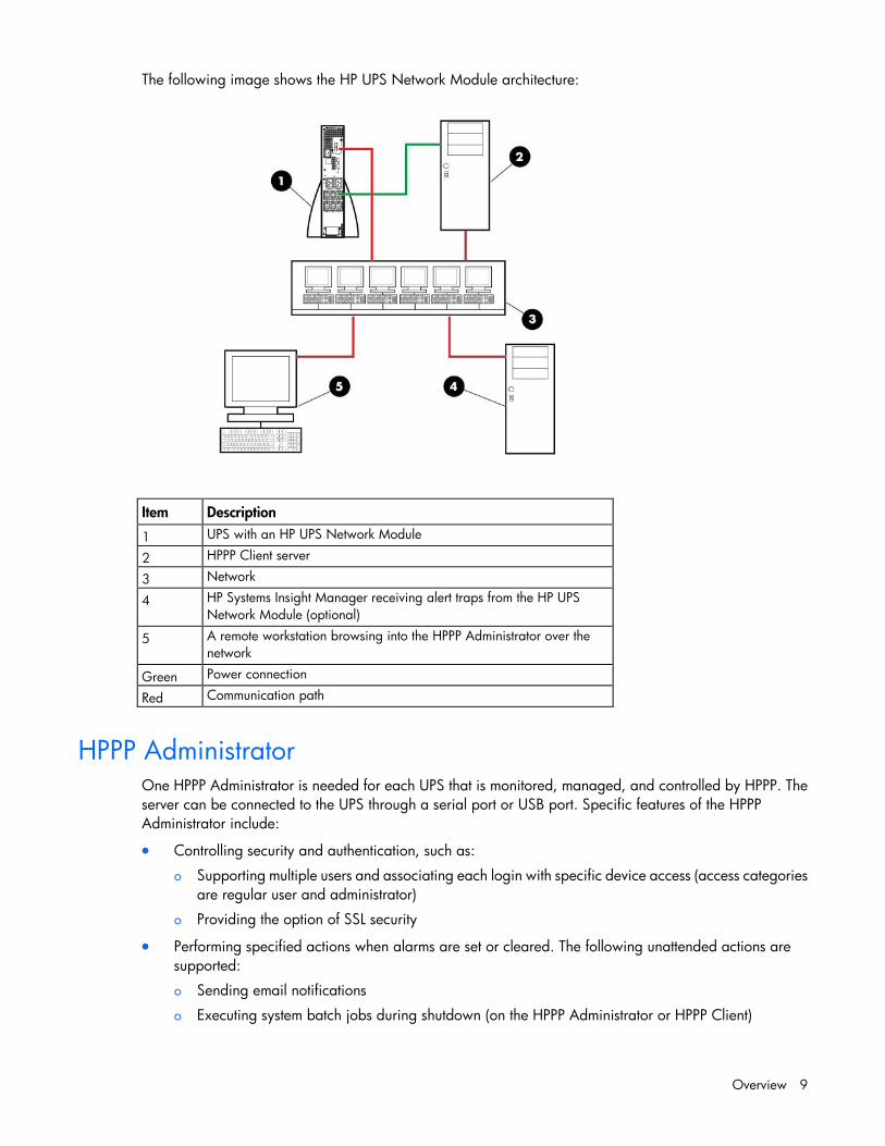
The following image shows the HP UPS Network Module architecture:
Item Description
1 UPS with an HP UPS Network Module
2 HPPP Client server
3 Network
4 HP Systems Insight Manager receiving alert traps from the HP UPS Network Module (optional)
5 A remote workstation browsing into the HPPP Administrator over the network
Green Power connection
Red Communication path
HPPP Administrator One HPPP Administrator is needed for each UPS that is monitored, managed, and controlled by HPPP. The server can be connected to the UPS through a serial port or USB port. Specific features of the HPPP Administrator include:
• Controlling security and authentication, such as:
o Supporting multiple users and associating each login with specific device access (access categories are regular user and administrator)
o Providing the option of SSL security
• Performing specified actions when alarms are set or cleared. The following unattended actions are supported:
o Sending email notifications
o Executing system batch jobs during shutdown (on the HPPP Administrator or HPPP Client)

Overview 10
o Performing operating system shutdown by notifying the HPPP Clients when to shut down
o Shutting down and restarting by load segment, if applicable
o Performing a UPS shutdown
• Performing a graceful, remote shutdown of the local operating system after a specified delay
• Maintaining event logs, which include the following types:
o UPS event log, which contains UPS-related events, such as the UPS going on battery
o Application event log, which contains application-related events, such as failed logins or settings changes
• Logging data variables. The following data values are logged:
NOTE: Depending on the specific UPS model, some variables might not be supported. The following list is only an example.
o Input voltage
o Input current
o Input frequency
o Output voltage
o Output current
o Output frequency
o Output load
o Output active power
o Output apparent power
o Battery temperature
o Runtime
o Battery output voltage
o Battery capacity
• Providing content for the user interface using an embedded web server.
IMPORTANT: Power protection for the HPPP Administrator is essential. The HPPP Administrator is the central point of control of the power management environment. If the HPPP Administrator goes down, the ability to gracefully shut down attached servers is lost.
NOTE: For the latest supported operating systems, see the HP website (http://www.hp.com/go/rackandpower).
HPPP Client The HPPP Administrator provides both status and shutdown information to the HPPP Client. The HPPP Client runs on a server and allows the software to gracefully shut down the operating system of that server and run a script during power failure. Install the HPPP Client on any server that is powered by the UPS and any server that the software uses to initiate a command. However, it is not necessary to install the HPPP Client on the server running the HPPP Administrator component.

Overview 11
NOTE: For the latest supported operating systems, see the HP website (http://www.hp.com/go/rackandpower).
Supported hardware configurations HPPP requires that the HPPP Administrator and the servers running the HPPP Clients are connected to the network. UPSs can be attached in any of the following configurations:
• Configuration A (on page 11)—An HPPP Administrator is serially attached to one UPS.
• Configuration B (on page 12)—One HPPP Administrator is serially attached to a UPS and communicates to several HPPP Clients over the network.
• Configuration C (on page 13)—An HPPP Administrator is attached to one UPS through the USB port.
• Configuration D (on page 13)—One HPPP Administrator is attached to a UPS through the USB port and communicates to several HPPP Clients over the network.
• Configuration E (on page 14)—One or more HPPP Clients are powered by a UPS and communicate with one UPS Network Module over the network.
• Configuration F (on page 15)—One or more HPPP Clients are redundantly powered by two UPSs and communicate with two UPS Network Modules over the network.
Configuration A This figure illustrates a UPS serially attached to an HPPP Administrator that is plugged into a load segment of the UPS. The HPPP Administrator is connected directly to the network. A remote workstation can browse into the HPPP Administrator over the network.
Item Description
1 Remote workstation browsing into the HPPP Administrator over the network
2 HPPP Administrator
3 UPS
4 Network
Green Power connection
Red Communication path
Black Serial connection

Overview 12
Configuration B This figure illustrates one server as an HPPP Administrator and it is serially attached to the UPS. This HPPP Administrator communicates to the HPPP Client servers over the network to begin a graceful shutdown in the event of a power failure or other configured shutdown events.
NOTE: Up to 35 HPPP Clients can be managed by one HPPP Administrator.
Item Description
1 UPS
2 HPPP Administrator
3 HPPP Client server
4 HPPP Client server
5 Network
6 Remote workstation browsing into the HPPP Administrator or Client over the network
Green Power connection
Red Communication path
Black Serial connection

Overview 13
Configuration C This figure illustrates a UPS that is connected to the HPPP Administrator through a USB port. The HPPP Administrator is plugged into a load segment of the UPS and connected directly to the network. A remote workstation can browse into the HPPP Administrator over the network.
Item Description
1 Remote workstation browsing into the HPPP Administrator over the network
2 HPPP Administrator
3 UPS
4 Network
Green Power connection
Red Communication path
Black USB connection
Configuration D This figure illustrates one server as an HPPP Administrator and it is attached to a UPS through the USB port. The HPPP Administrator communicates to the HPPP Client servers over the network to begin a graceful shutdown in the event of a power failure or other configured shutdown events.
NOTE: Up to 35 HPPP Clients can be managed by one HPPP Administrator.

Overview 14
Item Description
1 UPS
2 HPPP Administrator
3 HPPP Client server
4 HPPP Client server
5 Network
6 Remote workstation browsing into the HPPP Administrator or Client over the network
Green Power connection
Red Communication path
Black USB connection
Configuration E This figure illustrates one or more HPPP Clients are powered by a UPS and communicates with one UPS Network Module over the network to begin a graceful shutdown in the event of a power failure or other configured shutdown events.
NOTE: Up to 35 HPPP Clients can be managed by one HP UPS Network Module.

Overview 15
Item Description
1 UPS with an HP UPS Network Module
2 HPPP Client server
3 HPPP Client server
4 HPPP Client server
5 Network
6 Remote workstation browsing into the HP UPS Network Module or HPPP Client over the network
Green Power connection
Red Communication path
Configuration F This figure illustrates one or more HPPP Clients are redundantly powered by two UPSs and communicate with two UPS Network Modules over the network to begin a graceful shutdown in the event of a power failure or other configured shutdown events.
NOTE: Up to 35 HPPP Clients can be managed by one HP UPS Network Module.

Overview 16
Item Description
1 UPS with an HP UPS Network Module
2 UPS with an HP UPS Network Module
3 HPPP Client server
4 HPPP Client server
5 Network
6 Remote workstation browsing into the UPS Network Module or HPPP Client over the network
Green Power connection
Red Communication path
Using the redundant configuration Before using a redundant configuration, verify the following:
• HP UPS Network Modules and HPPP Clients are installed.
• The two UPSs are the same model.
• The combined load of UPS 1 and UPS 2 does not exceed 50% of the single UPS load rating.
The redundant UPS feature is designed to maintain power to attached Clients in the event of a utility power fail condition to a single UPS. In the event of a single UPS power failure you might still experience a graceful shutdown of Clients if one of the following conditions is present with the unaffected UPS:
• The unaffected UPSs has a fault condition (Internal Failure, Overload, Communication Failure) or is in Bypass.
• The combined load of UPS 1 and UPS 2 exceeds 100% of a single UPS rated capacity.
• Both UPSs have a fault condition (Internal Failure, Overload, Communication Failure) or are in Bypass.

Overview 17
Setup overview To setup HPPP:
1. Visit the HP website (http://www.hp.com/go/rackandpower) to download the latest version of HPPP.
2. Connect all equipment powered by the UPS to the receptacles on the UPS rear panel. If the UPS has multiple load segments, note which load segment powers each device.
3. Power up the UPS and all attached equipment.
4. Be sure that the serial or USB cable connecting the UPS to the HPPP is properly installed.
5. Install the HPPP Administrator or Client software according to the instructions for your operating system. If the configuration does not contain an HP UPS Network Module, there must be one HPPP Administrator for each UPS.
6. Browse to the HPPP Administrator or Client.
7. Configure the power source on the Device Discovery screen (on page 50) for both the HPPP Administrator and the Client. Be sure to configure the Administrator power source before configuring the Client.
8. Configure the power fail settings on the Shutdown Parameters screen (on page 59).
9. Test shutdown.
10. Configure event actions on the Event Actions screen (on page 54).
11. Configure user accounts on the User Accounts screen (on page 68).
12. Configure system settings on the System screen (on page 66).

Installation 18
Installation
System requirements For a complete list of supported operating systems, web browser requirements, and supported hardware, see the HP website (http://www.hp.com/go/rackandpower).
Hardware and software Suggested minimum requirements
HPPP Administrator
Hardware 500-MHz processor
Disk space 10 MB free disk space
System memory 300 MB of RAM
HPPP Client
Hardware 500-MHz processor
Disk space 10 MB free disk space
System memory 300 MB of RAM
Installation overview Follow these guidelines when installing HPPP components:
• HPPP Administrator—Install the HPPP Administrator on the server that is connected to the UPS serial port or USB port.
• HPPP Client—Install the HPPP Client on any computer that is powered by the UPS.
For each component, there are three installation options:
• GUI installation—A series of dialog boxes and prompts guide you through the installation process.
• Non-GUI installation—A series of commands are necessary to complete the installation.
• Silent installation—The installer uses the default install path for the platform and no output displays for the user.
Silent installation is typically used by system administrators who have many installations that are configured identically and require minimal user interaction.
During a silent installation, install an HPPP Administrator or Client through the assisted installation method that is appropriate for the operating system.
The following table summarizes the available installation options for each operating system.
Operating system
GUI installation
Non-GUI installation
Silent installation
Local/remote installation
Windows Available Available Available -
Linux - Available Available -
HP-UX - Available Available Available

Installation 19
Installing HPPP on Windows operating systems HPPP can be installed using either a graphical installer or a silent installation on any supported Windows operating system. To ensure that your system meets the minimum requirements, see "System requirements (on page 18)."
Installing HPPP using the GUI installer on Windows systems
NOTE: Before installing the software, be sure that the serial or USB cable connecting the UPS to the server is properly installed.
To install HPPP using the GUI installer:
1. If the server is connected to the UPS through the USB port, verify that the UPS is detected by the operating system, and then click OK.
If the software has been downloaded from the HP website (http://www.hp.com/go/rackandpower), follow the instructions to unpack the files, and then locate and run the HPPP executable file.
The Welcome screen appears.

Installation 20
2. Verify that the device communication cables are connected, and then click Next.
The Select Path screen appears.
3. Click Install to install HPPP in the default folder. To specify a different folder, click the folder icon, navigate to the appropriate folder, and then click Install.
Installation 21
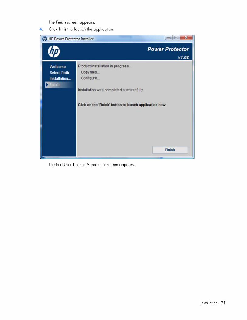
The Finish screen appears.
4. Click Finish to launch the application.
The End User License Agreement screen appears.

Installation 22
5. Read the license agreement, and then click Accept.
6. Log in to HPPP using the default credentials admin/admin, and then you are prompted to configure the
Power Protector as Administrator or Client.
The HP Power Protector Configuration screen appears.
7. Select the HPPP component that you are installing on this server, and then click Save.

Installation 23
Installing HPPP using the silent installation method on Windows systems
NOTE: Before installing the software, be sure that the serial or USB cable connecting the UPS to the server is properly installed.
During a silent installation, install an HPPP Administrator or Client through the assisted installation method that is appropriate for the operating system.
From the directory that contains the .exe file, execute the file with the -silent argument. c:\hppp_win_1_00_011.exe -silent
Uninstalling HPPP from Windows systems To uninstall using the HPPP shortcut:
1. Click Start>Programs>HP>Power Protector>Uninstall HP Power Protector.
2. Follow the prompts to uninstall the software.
To uninstall using the Windows Control Panel:
1. Click Start>Settings>Control Panel.
2. Open Add/Remove Programs.
3. Select HP Power Protector, and then click Change/Remove.
The uninstall wizard launches.
Select Remove Choice, and then click Next.
4. Follow the prompts in the uninstall wizard to uninstall the software.
To uninstall from the command line, execute the following command: <HPPP_install_path>\mc2.exe –uninstall
For example: c:\Program Files\HP\HP Power Protector\mc2.exe –uninstall
NOTE: Some files might remain following the uninstallation and can be removed manually.
Installing HPPP on Linux operating systems HPPP can be installed using the native package or generic package. To ensure that your system meets the minimum requirements, see "System requirements (on page 18)."
Before installing HPPP on RHEL IA64, install the following dependency: libunwind-0.98.5-5.el5.ia64.rpm
Installing HPPP using the GUI installer on Linux systems
NOTE: Before installing the software, be sure that the serial or USB cable connecting the UPS to the server is properly installed.
Installation 24
Native installation on a RedHat, SUSE, or derivative system
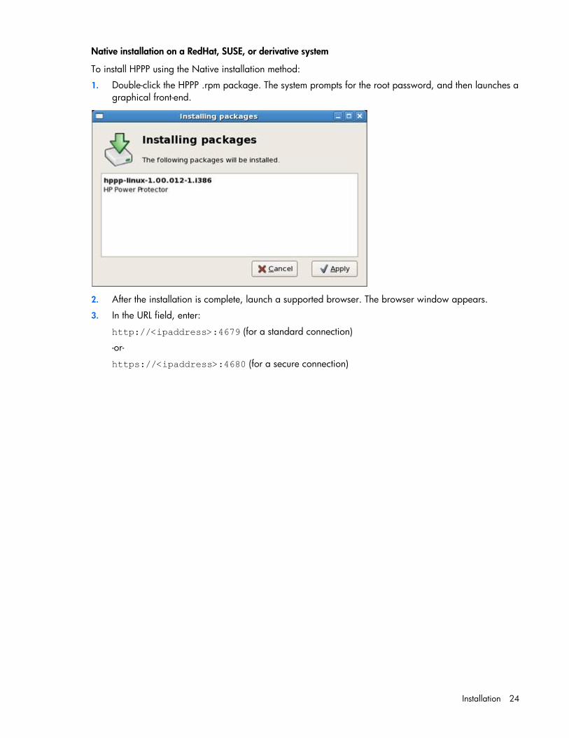
To install HPPP using the Native installation method:
1. Double-click the HPPP .rpm package. The system prompts for the root password, and then launches a graphical front-end.
2. After the installation is complete, launch a supported browser. The browser window appears.
3. In the URL field, enter:
http://<ipaddress>:4679 (for a standard connection)
-or-
https://<ipaddress>:4680 (for a secure connection)

Installation 25
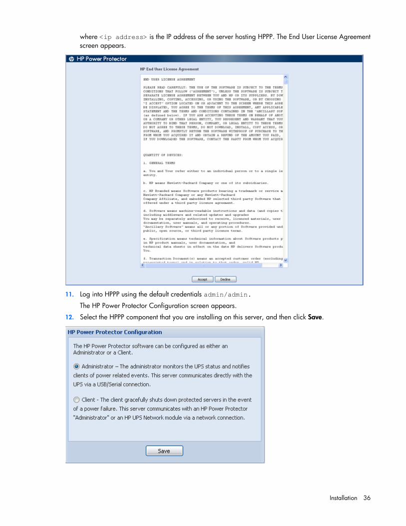
where <ip address> is the IP address of the server hosting HPPP. The End User License Agreement screen appears.
4. Log into HPPP using the default credentials admin/admin.
The HP Power Protector Configuration screen appears.
5. Select the HPPP component that you are installing on this server, and then click Save.

Installation 26
Installing HPPP using the CLI on Linux systems
NOTE: Before installing the software, be sure that the serial or USB cable connecting the UPS to the server is properly installed.
Native installation on a RedHat, SUSE, or derivative system
To install HPPP from a command line:
1. Execute the following command (as root): $ rpm -i hppp-linux_X.Y.Z.rpm
2. After the installation is complete, launch a supported browser. The browser window appears.
3. In the URL field, enter:
http://<ipaddress>:4679 (for a standard connection)
-or-
https://<ipaddress>:4680 (for a secure connection)

Installation 27
where <ip address> is the IP address of the server hosting HPPP. The End User License Agreement screen appears.
4. Log into HPPP using the default credentials admin/admin.
The HP Power Protector Configuration screen appears.
5. Select the HPPP component that you are installing on this server, and then click Save.
Generic installation

Installation 28
If your system does not derive from RedHat (using .rpm), you can install HPPP using the Generic Package.
To install HPPP from a command line:
1. Execute the following command from where the generic installer is located (as root): $ hppp-linux-x_yz-i386 -install
2. Verify that the device communication is connected, and then enter Y to proceed with the installation.
3. Press Enter to use the default installation path or enter the new installation path, and then press Enter.
4. Enter Y to confirm the install directory.
5. After the installation is complete, launch a supported browser. The browser window appears.
6. In the URL field, enter:
http://<ipaddress>:4679 (for a standard connection)
-or-
https://<ipaddress>:4680 (for a secure connection)

Installation 29
where <ip address> is the IP address of the server hosting HPPP. The End User License Agreement screen appears.
7. Log into HPPP using the default credentials admin/admin.
The HP Power Protector Configuration screen appears.
8. Select the HPPP component that you are installing on this server, and then click Save.

Installation 30
Installing HPPP using the silent installation method on Linux systems
NOTE: Before installing the software, be sure that the serial or USB cable connecting the UPS to the server is properly installed.
During a silent installation, install an HPPP Administrator or Client through the assisted installation method that is appropriate for the operating system.
To install HPPP using the silent installation method:
1. Execute the file: hppp-linux-x_y_z-i386 -silent
2. After the installation is complete, launch a supported browser. The browser window appears.
3. In the URL field, enter:
http://<ipaddress>:4679 (for a standard connection)
-or-
https://<ipaddress>:4680 (for a secure connection)

Installation 31
where <ip address> is the IP address of the server hosting HPPP. The End User License Agreement screen appears.
4. Log into HPPP using the default credentials admin/admin.
The HP Power Protector Configuration screen appears.
5. Select the HPPP component that you are installing on this server, and then click Save.

Installation 32
Uninstalling HPPP from Linux systems Native uninstallation on a RedHat, SUSE, or derivative system
To uninstall HPPP from the command line, execute the following command: rpm –e hppp-linux
Generic uninstallation
To uninstall HPPP using the Generic Package:
1. From the command line, execute the following command: <HPPP install path>mc2 –uninstall
For example: # /usr/local/HP/Power Protector/mc2 -uninstall
2. Enter Y to proceed with the uninstallation.
3. Enter Y to remove all files created by the application.
4. Enter Y to confirm removing Power Protector.
NOTE: Some files might remain following the uninstallation and can be removed manually.

Installation 33
Installing HPPP on HP-UX operating systems HPPP can be installed using the SAM or Generic Package installation option on any supported HP-UX operating system. To ensure that your system meets the minimum requirements, see "System requirements (on page 18)."
Installing HPPP locally using the Generic Package method
NOTE: Before installing the software, be sure that the serial cable connecting the UPS to the server is properly installed.
To install HPPP using the Generic Package:
1. From the command line, execute the following command: ./hppp—hp-ux-x_y_z-ia64 -install
2. Verify that the device communication is connected, and then enter Y to proceed with the installation.
3. Press Enter to use the default installation path or enter the new installation path, and then press Enter.
4. Enter Y to confirm the install directory.
5. After the installation is complete, launch a supported browser. The browser window appears.
6. In the URL field, enter:
http://<ipaddress>:4679 (for a standard connection)
-or-
https://<ipaddress>:4680 (for a secure connection)

Installation 34
where <ip address> is the IP address of the server hosting HPPP. The End User License Agreement screen appears.
7. Log into HPPP using the default credentials admin/admin.
The HP Power Protector Configuration screen appears.
8. Select the HPPP component that you are installing on this server, and then click Save.

Installation 35
Installing HPPP locally using the SAM method
NOTE: Before installing the software, be sure that the serial cable connecting the UPS to the server is properly installed.
To install HPPP using the SAM method:
1. From the SAM application, double-click Software Management.
2. Click Install Software to Local Host.
3. Change the Source Depot Path to a fully qualified path and depot name.
4. Select the HP Power Protector you are about to install.
5. Click Actions>Install from the top menu.
6. Click OK to analyze the depot file.
7. Click OK to install the depot file.
8. Click Done to complete the installation and continue with the configuration process.
9. After the installation is complete, launch a supported browser. The browser window appears.
10. In the URL field, enter:
http://<ipaddress>:4679 (for a standard connection)
-or-
https://<ipaddress>:4680 (for a secure connection)
Installation 36
where <ip address> is the IP address of the server hosting HPPP. The End User License Agreement screen appears.
11. Log into HPPP using the default credentials admin/admin.
The HP Power Protector Configuration screen appears.
12. Select the HPPP component that you are installing on this server, and then click Save.
Installation 37
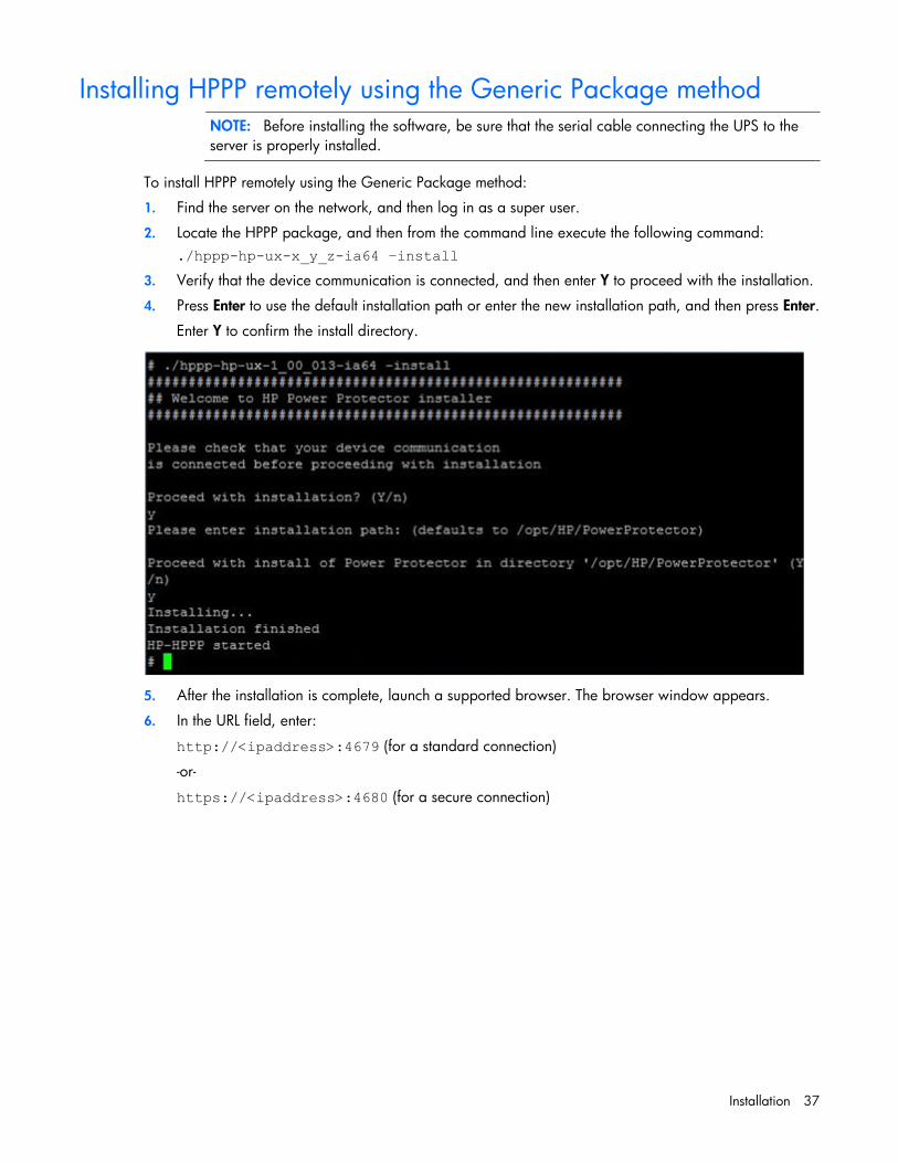
Installing HPPP remotely using the Generic Package method
NOTE: Before installing the software, be sure that the serial cable connecting the UPS to the server is properly installed.
To install HPPP remotely using the Generic Package method:
1. Find the server on the network, and then log in as a super user.
2. Locate the HPPP package, and then from the command line execute the following command: ./hppp-hp-ux-x_y_z-ia64 –install
3. Verify that the device communication is connected, and then enter Y to proceed with the installation.
4. Press Enter to use the default installation path or enter the new installation path, and then press Enter.
Enter Y to confirm the install directory.
5. After the installation is complete, launch a supported browser. The browser window appears.
6. In the URL field, enter:
http://<ipaddress>:4679 (for a standard connection)
-or-
https://<ipaddress>:4680 (for a secure connection)

Installation 38
where <ip address> is the IP address of the server hosting HPPP. The End User License Agreement screen appears.
7. Log into HPPP using the default credentials admin/admin.
The HP Power Protector Configuration screen appears.
8. Select the HPPP component that you are installing on this server, and then click Save.

Installation 39
Installing HPPP remotely using the SAM method
NOTE: Before installing the software, be sure that the serial cable connecting the UPS to the server is properly installed.
To install HPPP remotely using the SAM method:
1. From a remote machine, enter sam at the command line prompt.
2. Click Software Management.
3. Click Install Software to Local Host.
4. Change the Source Depot Path to a fully qualified path and depot name.
5. Select the HP Power Protector you are about to install.
6. Select Actions>Install from the top menu, and click OK and Done.
7. Click OK to analyze the depot file.
8. Click OK to install the depot file.
9. Click Done to complete the installation and continue with the configuration process.
10. After the installation is complete, launch a supported browser. The browser window appears.
11. In the URL field, enter:
http://<ipaddress>:4679 (for a standard connection)
-or-
https://<ipaddress>:4680 (for a secure connection)

Installation 40
where <ip address> is the IP address of the server hosting HPPP. The End User License Agreement screen appears.
12. Log into HPPP using the default credentials admin/admin.
The HP Power Protector Configuration screen appears.
13. Select the HPPP component that you are installing on this server, and then click Save.
Installation 41
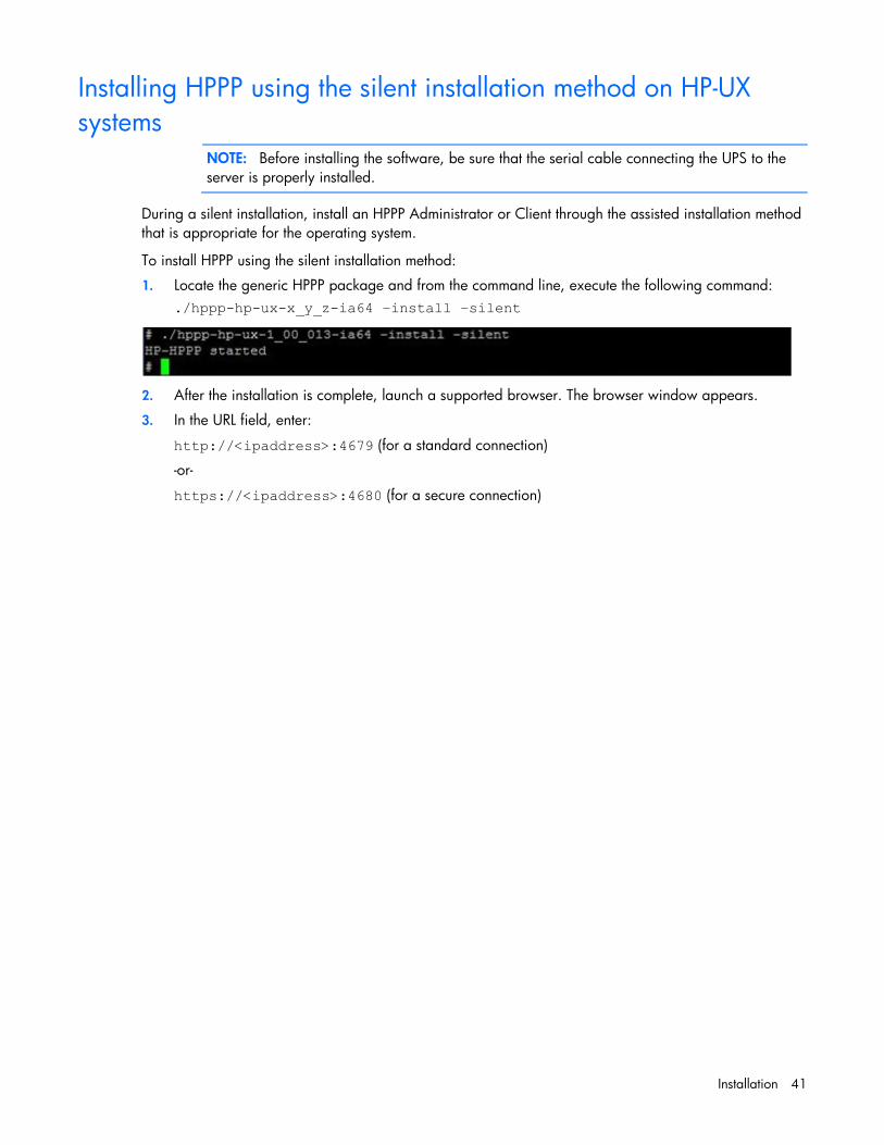
Installing HPPP using the silent installation method on HP-UX systems
NOTE: Before installing the software, be sure that the serial cable connecting the UPS to the server is properly installed.
During a silent installation, install an HPPP Administrator or Client through the assisted installation method that is appropriate for the operating system.
To install HPPP using the silent installation method:
1. Locate the generic HPPP package and from the command line, execute the following command: ./hppp-hp-ux-x_y_z-ia64 –install –silent
2. After the installation is complete, launch a supported browser. The browser window appears.
3. In the URL field, enter:
http://<ipaddress>:4679 (for a standard connection)
-or-
https://<ipaddress>:4680 (for a secure connection)

Installation 42
where <ip address> is the IP address of the server hosting HPPP. The End User License Agreement screen appears.
4. Log into HPPP using the default credentials admin/admin.
The HP Power Protector Configuration screen appears.
5. Select the HPPP component that you are installing on this server, and then click Save.

Installation 43
Uninstalling HPPP from HP-UX systems To uninstall HPPP:
1. From the command line, execute the following command: <HPPP install path>mc2 –uninstall
For example: # /opt/HP/HP Power Protector/mc2 -uninstall
2. Enter Y to proceed with the uninstallation.
3. Enter Y to remove all files created by the application.
4. Enter Y to confirm removing Power Protector.
NOTE: Some files might remain following the uninstallation and can be removed manually.
Access and navigation 44
Access and navigation
Accessing the software You can access the software:
• Remotely through a web browser (on page 44)
• Locally from the Start menu in Windows
Web browser To access HPPP through a web browser:
1. Launch a supported browser. The browser window appears.
2. In the URL field, enter an IP address. Use the following examples, where hostname is the IP address or the machine name of the computer on which HPPP is installed.
o http://hostname:4679
o https://hostname:4680
NOTE: If you are using a proxy server, you might need to add the server hosting the software to the No Proxy list of servers in the Internet settings for your browser. Refer to the browser help for more information about changing the configuration.
Start menu To access HPPP from the Start menu, go to Start>Programs>HP>HP Power Protector.
On Windows and Linux when a graphic environment is available, the installer creates shortcuts in the system applications menu.
Operating system Icon Description
Windows
Open a web browser page on the HPPP web interface URL
Start HPPP service
Stop HPPP service
Uninstall HPPP
Linux
Open a web browser page on the HPPP web interface URL
System tray icon The system tray icon is only available when HPPP is installed on a Windows operating system. Right-click the system tray icon to access a shortcut to the following HPPP functionality:

Access and navigation 45
• Open the notification window
• Open the web interface
• Stop HPPP
• Start HPPP
To view the status of HPPP through the system tray icon, do one of the following:
• Hover over the system tray icon on a computer with one of the software components installed.
• Right-click the software system tray icon on a computer with one of the software components installed to display a context menu.
Icon Status
The power source is not configured.
The HPPP service stopped.
Power is present at the power source.
On Battery—The battery capacity is 100%.
On Battery—The battery capacity is 80%.
On Battery—The battery capacity is 60%.
On Battery—The battery capacity is 40%.
On Battery—The battery capacity is 20%.
A warning event occurred.
A critical event occurred.
Communication with the power source failed.
Notification window When a power source is configured, the HP Power Protector Notifications window appears with the following information:
• Name of the power source
• Power source status—On utility or On battery
• Battery capacity
• Battery run time
• Status icon
• Messages—The previous ten events that occurred on the power source separated into four columns:
o Event status icon
o Identifier of the power source
o Date of the event
o Description of the event
NOTE: On a Linux operating system, the Messages list is not limited to ten events, and can be sorted.
For more information about status icons, see "Access by Start menu ("Start menu" on page 44)."

Access and navigation 46
When in redundant configuration, no power source information appears; only the Messages list appears.
Browser security alert
NOTE: The information in this section is only applicable if SSL is chosen during software configuration.
Secure browsing requires the use of SSL. SSL is a protocol layer that lies between HTTP and TCP that provides secure communication between a server and a client and is designed to provide privacy and message integrity. SSL is commonly used in web-based transactions to authenticate the web server, which indisputably identifies the server to the browser. SSL also provides an encrypted channel of communication between the server and the browser. The encrypted channel ensures integrity of the data between the web server and the browser, so that data can neither be viewed nor modified while in transit. HPPP uses a system generated and unique key.
An integral part of SSL is a security certificate, which identifies the device. If your browser displays a security alert when browsing to the device, it can be for one of several reasons:
• The certificate is untrusted, meaning it was signed by a certifying authority that is unknown to your browser.
• The certificate has expired or is not yet valid. This condition can occur if you issue your own certificate and it has expired.
• The name on the certificate does not match the name of the site in the browser address field.
For more information about security considerations, see "Security considerations overview (on page 102)."
Establishing a secure session for Internet Explorer The first time you browse to the device, the Secure Session screen appears. To ensure a secure connection, verify that you are browsing to the desired device:
1. Click View Certificate.

Access and navigation 47
2. Verify that the name in the Issued To field is the name of your device.
3. Perform any other steps necessary to verify the identity of the device.
CAUTION: If you are not sure this is the desired device, do not proceed. Importing a certificate from an unauthorized source relays your login credentials to that unauthorized source. Exit the certificate window and contact the system administrator.
After verifying the device, do one of the following:
• Import the certificate and proceed.
a. Click View Certificate. The certificate appears.
b. Click Install Certificate. The Certificate Import wizard runs.
c. Click Next. The Certificate Store screen appears.
d. Select Automatically select the certificate store based on the type of certificate, and then click Next.
e. Click Finish. A message appears, asking for verification of the root store.
f. Click Yes.
• Proceed without importing the certificate by clicking Yes at the Security Alert window. You continue to receive the Security Alert each time you log in until you import the certificate. Your data is still encrypted.
• Exit and import the certificate into your browser from a file provided by the administrator.
a. Click No at the Security Alert window.
b. Obtain an exported certificate file from the administrator.
NOTE: If using Internet Explorer, you can manually import the file into the browser by clicking Tools>Internet Options>Content>Certificates>Import.
Establishing a secure session for Mozilla The first time you browse to the device, the Secure Session screen appears. To ensure a secure connection, verify that you are browsing to the desired device:
1. Click Examine Certificate.
2. Verify that the name in the Issued To field is the name or IP address of your device.
3. Perform any other steps necessary to verify the identity of the device.
4. After verifying the device, do one of the following:
a. Click either Accept this certificate permanently or Accept this certificate temporarily for this session.
b. Click OK.
NOTE: If using Mozilla, you can manually import the file into the browser by clicking Edit>Preferences>Privacy & Security>Certificates>Manage Certificates>Authorities>Import.
Establishing a secure session for Firefox The first time you browse to the device, the Secure Session screen appears. To ensure a secure connection, verify that you are browsing to the desired device:
1. Click Examine Certificate.
2. Verify that the name in the Issued To field is the name or IP address of your device.

Access and navigation 48
3. Perform any other steps necessary to verify the identity of the device.
4. After verifying the device, do one of the following:
a. Click either Accept this certificate permanently or Accept this certificate temporarily for this session.
b. Click OK.
NOTE: If using Firefox, you can manually import the file into the browser by clicking Edit>Preferences>Advanced>Security>View Certificates>Authorities>Import.
Signing in Before using this software, log in with a user name and password. The first time you log in, enter admin as the user name, and enter admin as the password. Click Login to log in. After you are logged in, you can change your password. For more information, see "User Accounts screen (on page 68)."
NOTE: Passwords are case-sensitive.
After a successful login, the Power Source screen appears.
A quick scan discovers all available power sources. For an Administrator, all USB or serially connected UPSs are discovered. For a Client, all HPPP Administrators and UPS Network Modules accessible through the network are discovered.
Navigating the interface The web interface is divided into two frames:
• Menu tree—Contains a list of menu options on the left side of the screen
• Main frame—Contains the various interface screens based on the menu option selected in the left navigation frame
Click Help to view online help.

Access and navigation 49
NOTE: The number of active alarms by severity appears in the lower-left corner.

Configuration and operation 50
Configuration and operation
Settings Menu options listed under Settings include:
• Device Discovery ("Device Discovery screen" on page 50)
• Event Actions ("Event Actions screen" on page 54)
• Shutdown Parameters ("Shutdown Parameters screen" on page 59)
• System ("System screen" on page 66)
• User Accounts ("User Accounts screen" on page 68)
Device Discovery screen Click Device Discovery in the menu tree to display the Device Discovery screen. This screen allows an administrator to discover attached UPSs and UPS Network Modules or HPPP Administrators, edit the UPS or application information, remove a discovered UPS or application, and configure the power source and redundancy.
Device discovery is used by both HPPP Administrators and HPPP Clients. HPPP Administrators can discover serial and USB connected UPSs. HPPP Clients can discover HPPP Administrators and UPS Network Modules.
Click a column header to sort the Node List. To customize the columns, select Columns, and then select the checkboxes that correspond to the data you want to include. Available column options include:
• Type—An icon indicating the node type

Configuration and operation 51
• Status—An icon indicating the current status of the communication between the Administrator and the
Client ( Normal or Communication Loss)
• IP address—The IP address of the node
• MAC address—The MAC address of the node
• Description—A description of the node
• Serial number—The serial number of the node
• Class—The device type, for example, RS-232 device, USB device, HP Power Protector, or UPS Network Module
• OS type—The node operating system
• Location—The node location
• Contact—The contact person for the node
• User type—A user-defined value that can be used to sort devices throughout the web interface
The user type can be specified by editing a device.
• User note—A user-defined message that can be used to sort devices
• Access—The status of the HPPP Client’s login credentials to the HPPP Administrator (must be an administrator level user name and password)
• Link—A link to the web interface for the agent ( HTTP Connection, HTTPS Connection, or Communication Loss)
• Load alarm threshold—A user specified threshold value that, if exceeded, triggers an event
On the Device Discovery screen:
1. Discover USB- and serially-connected UPSs using the HPPP Administrator. To manually discover USB and serial devices that are connected after the application is launched, click Quick scan.
2. Discover network-connected HPPP Administrators and UPS Network Modules using the HPPP Client. To manually discover devices:
o Click Quick scan to discover HPPP Administrators and UPS Network Modules that are connected after the application is launched.
o Click Range scan to discover HPPP Administrators and UPS Network Modules that are outside the network segment. The Range scan screen appears.
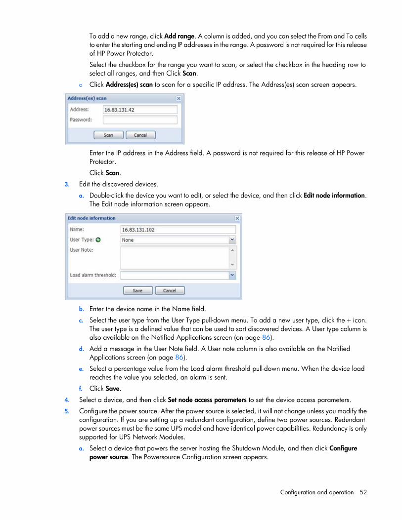
Configuration and operation 52
To add a new range, click Add range. A column is added, and you can select the From and To cells to enter the starting and ending IP addresses in the range. A password is not required for this release of HP Power Protector.
Select the checkbox for the range you want to scan, or select the checkbox in the heading row to select all ranges, and then Click Scan.
o Click Address(es) scan to scan for a specific IP address. The Address(es) scan screen appears.
Enter the IP address in the Address field. A password is not required for this release of HP Power Protector.
Click Scan.
3. Edit the discovered devices.
a. Double-click the device you want to edit, or select the device, and then click Edit node information. The Edit node information screen appears.
b. Enter the device name in the Name field.
c. Select the user type from the User Type pull-down menu. To add a new user type, click the + icon. The user type is a defined value that can be used to sort discovered devices. A User type column is also available on the Notified Applications screen (on page 86).
d. Add a message in the User Note field. A User note column is also available on the Notified Applications screen (on page 86).
e. Select a percentage value from the Load alarm threshold pull-down menu. When the device load reaches the value you selected, an alarm is sent.
f. Click Save.
4. Select a device, and then click Set node access parameters to set the device access parameters.
5. Configure the power source. After the power source is selected, it will not change unless you modify the configuration. If you are setting up a redundant configuration, define two power sources. Redundant power sources must be the same UPS model and have identical power capabilities. Redundancy is only supported for UPS Network Modules.
a. Select a device that powers the server hosting the Shutdown Module, and then click Configure power source. The Powersource Configuration screen appears.

Configuration and operation 53
Powersource Configuration screen for HPPP Administrators
Powersource Configuration screen for HPPP Clients
b. The Source ID field displays the UPS currently selected as the power source. All the UPSs detected
locally or over the network appear in the pull-down menu. Select a different device to change the power source.
c. Select the load segment that powers the server hosting the Shutdown Module from the Load segment pull-down menu.
d. If the power source is a UPS Network Module or an HPPP Administrator, enter the login name in the Login field. HP Power Protector accesses the UPS Network Module to set values, such as the shutdown duration.
e. If the power source is a UPS Network Module or an HPPP Administrator, enter the login password in the Password field. HP Power Protector accesses the UPS Network Module to set values, such as the shutdown duration.
f. If the power source is a UPS Network Module and is part of a redundant UPS configuration, select the Is this machine protected by redundancy? check box. The screen expands and provides options for selecting and configuring the second (redundant) UPS power source.
g. Click Save.
6. If you need to delete a device, select the device you want to delete, and then press Delete or click Remove node.
Click Help to view online help.

Configuration and operation 54
Event Actions screen Click Event Actions in the menu tree to display the Event Actions screen. This screen allows an administrator to configure the way users are notified when UPS and application events occur.
To add an event action:
1. Click Create new action. The Create new action screen appears. Fields marked with an asterisk must be completed.
2. Select or clear the Action enabled checkbox to enable or disable the action.
3. Enter a name for the action in the Action name field.
4. Filter the events that will trigger the action by selecting the checkboxes for the appropriate event severities. If you configure the action to only filter critical events, notification of normal events associated with the resolution of the critical events will not be sent.
5. Filter the events that will trigger the action by adding categories to the Event categories field:

Configuration and operation 55
a. Click the pen icon to display the Edit event categories screen.
b. Select the checkboxes for the categories you want to include, and then click Save.
6. Select the power source from the From power source pull-down menu. This setting is used in redundant configurations to activate actions on Power Source 1, Power Source 2, and Power Source 1 and 2.
7. Select the type of action from the Action type pull-down menu. Depending on the option you select, additional parameters appear.
o Notification—Includes a notification of the event in the system tray.
No additional parameters are required.
o Command—Executes a script.
Enter the command in the Command field. Click the pen icon to display the Edit command screen for help customizing your command. Click the + icon to insert a variable.
To execute a program for UPS events, the program path is required. The program is executed under the SYSTEM account. It might be necessary to modify the context before certain actions can be run. The full path must be provided to execute a script.

Configuration and operation 56
To allow a user to run specific tools and programs with permissions that are different from those assigned to the user account, use the Windows RunAs command, which allows you to save the password (Windows XP SP2 and later versions). Use the following Microsoft command:
runas /profile /user:<my login> /savecred <my_program.exe>
Upon the first execution, a password is required. The password is saved for subsequent executions.
For Linux, the HP Power Protector process runs under root privilege, and SUDO is not needed to execute a program or shell script.
o Email—Sends an email notification.
The email messages sent by HPPP are compatible with mobile transfer telephone systems using the SMS standard for text messaging. Send text messages using the following syntax: cellphone-number@SMS-Gateway
The required format may vary, depending on the cellular service provider. Contact your cellular service provider for Mail to SMS gateway settings.
— SMTP server—The host name or IP address of the SMTP server used to transfer email messages.
— Login—The user name for SMTP server authentication.
— Password—The password for SMTP server authentication.
— Recipient—The email address of the recipient.
You can specify multiple recipients by separating the addresses with a comma.
— Sender—The address for the source of email messages.
— Subject—The text included in the email message subject lines.

Configuration and operation 57
The subject can be customized with predefined variables. Click the pen icon to display the Edit subject screen for help customizing the subject. Click the + icon to insert a variable.
— Message—Identifies the event generating the message.
The body of the email can be customized with predefined variables. Click the pen icon to display the Edit message screen for help customizing the message. Click the + icon to insert a variable.
— Notification interval—Allows you to consolidate email notifications, which are only received
after a specified period of time.
Available options are None, Every 10 seconds, Every minute, Every hour, and Every day. For example, if you select Every day, you receive one email per day that details all the events that occurred over the last 24 hours. If you select None, each event generates an email, and you will receive more messages for the same number of events.
8. Click Save.

Configuration and operation 58
To copy a configured action:
1. Select the action, and then click Copy selected action. The Copy this action screen appears.
2. Enter a name for the action in the Action name field.
3. Click Save.
To edit a configured action:
1. Double-click the action, or select the action, and then click Edit selected action. The Edit action screen appears.
2. Modify the information as necessary.
3. Click Save.
To test a configured action, select the action, and then click Test selected action. The selected action is performed, allowing you to test the behavior.
To remove a configured action, select the action, and then click Remove selected action.
Click Help to view online help.

Configuration and operation 59
Shutdown Parameters screen Click Shutdown Parameters in the menu tree to display the Shutdown Parameters screen. This screen is available to both HPPP Administrators and Clients and allows an administrator to configure how HP Power Protector should shut down and restart the UPS and attached devices in the event of a power failure.
Verify the Power source configuration information provided. The power source must be configured before shutdown parameters can be configured. To configure the power source, see "Device Discovery screen (on page 50)".
To enter shutdown parameters:
1. Double-click the Shutdown Configuration entry, or click Edit shutdown configuration. The Edit shutdown configuration screen appears.
2. In the Shutdown initiated after (sec) field, enter the number of seconds that should elapse from the time
of a utility power failure until the UPS shutdown sequence is initiated. Record the longest time of all HPPP Clients for a UPS configuration. Configure a Shutdown initiated after time that is equal to or greater than the longest HPPP Client time in the HPPP Administrator.

Configuration and operation 60
3. In the OS shutdown time (sec) field, enter the shutdown delay needed to properly shut down the server. The UPS Network Module compares this time for all configured HPPP Clients and uses the longest time for OS shutdown time in the UPS Network Module Shutdown Parameters screen.
4. Select one of the following options from the Shutdown type pull-down menu:
o Hibernate—This option ensures that if the system is shut down, all work in progress and system information is automatically saved to the disk. The computer itself is de-energized. When utility power returns, all applications reopen exactly as they were, and the user placed back into their work environment.
The hibernate function, if available with your operating system, must be activated in the operating system. Select Start > Control Panel > Power Options and verify that the Hibernate option is activated on the Hibernate tab. If you select the Hibernate option and your computer does not support this function, HP Power Protector will perform a normal (default) shutdown.
o Shutdown—This option shuts down your applications and the system, but it does not de-energize the computer. The system offers the user the choice to de-energize the computer, in which case the UPS cuts power. On most computers, this configuration is necessary if you want the server to restart as soon as utility power is restored.
o Shutoff—This option shuts down your applications and the system, and de-energizes the computer. This configuration is recommended if you want to be available when the system restarts (or for load shedding).
o Script—This option manages the shutdown using a custom script that you can create to customize your own shutdown sequence. You can integrate the standard Windows shutdown command. For more information, run the shutdown /? command in a Windows Command Line interpreter. An example script is located in the following folder: <installation path>\configs\scripts
5. In the Shutdown script field, enter the absolute path of the script.
6. Select the Load segment shutoff enabled checkbox to. This checkbox is available for HPPP Administrators, as well as HPPP Clients that are connected to an HPPP Administrator.
7. Click Save.
To configure advanced shutdown criteria:
1. Click Edit advanced shutdown criteria. The Edit advanced shutdown criteria screen appears.
The HPPP software automatically uses the shutdown configuration parameters to gracefully shutdown the device for the following events:
o Remaining battery capacity below limit
o Remaining battery runtime below limit

Configuration and operation 61
o Utility power failed and the shutdown timer expired
o UPS shutdown is imminent
Configure additional shutdown options in step 2.
2. Select the checkboxes as necessary:
o UPS internal failure—A shutdown sequence is initiated at the first occurrence of a UPS Internal Failure alarm on at least one power source.
o UPS overload—A shutdown sequence is initiated at the first occurrence of a UPS Overload alarm on at least one power source.
o Output on bypass—A shutdown sequence is initiated at the first occurrence of a UPS On Bypass alarm on at least one power source.
o Communication Failure—A shutdown sequence is initiated at the first occurrence of a communication lost alarm.
3. Click Save.
To configure UPS settings (HPPP Administrators only):
1. Click Edit UPS Configuration. The Edit UPS Configuration screen appears.
2. In the Shutdown if remaining capacity under (%) field, enter the minimum amount of battery life that can
remain before the UPS shutdown sequence starts (0 to 100%, 20% by default).
3. In the Restart if capacity exceeds (%) field, enter the percentage of battery charge that must be available before restarting the UPS after AC power is restored (0 to 100%, 0% by default).
4. In the Load segment #1 restart delay (sec) field, enter the number of seconds after the UPS restarts that the UPS should wait before restarting load segment #1 (from 0 to 99999 seconds, 30 seconds by default).
5. In the Load segment #2 restart delay (sec) field, enter the number of seconds after the UPS restarts that the UPS should wait before restarting load segment #2 (from 0 to 99999 seconds, 30 seconds by default).
IMPORTANT: Carefully plan the restart settings configuration. You might experience an additional delay before servers power up, even though utility power is restored.
Click Help to view online help.
Configuring the shutdown parameters Follow these shutdown principles when configuring the shutdown parameters:
• The Shutdown initiated after (SIA) value entered for the HPPP Administrator must be equal to or greater than the HPPP Client configured with the longest SIA time. Otherwise, the Client starts to shutdown at the same time as the HPPP Administrator.

Configuration and operation 62
• The Operating system shutdown time (OST) value entered for the HPPP Administrator must be equal to or greater than the HPPP Client configured with the longest OST.
• After the operating system shutdown begins, the shutdown process cannot be canceled, even if utility power is restored.
• For load shedding, each Client is shutdown based on its own delay settings. This increases the backup time for the remaining Clients.
• The UPS is powered down after all load segments are powered down.
• If any other condition, such as if Battery capacity under, happen during SIA, the HPPP Administrator sends a shutdown command to all Clients, and then starts the shutdown process earlier.
This following example describes the shutdown parameters for a UPS with two load segments, one connected server that has HPPP Administrator installed, and three connected servers that have HPPP Clients installed on each server.
Item Description
1 Utility failure
2 Utility restore
3 Utility
4 Client 1on load segment 1
5 Client 2 on load segment 1
6 Load segment 1
7 Client 3 on load segment 2
8 Administrator on load segment 2
9 Load segment 2
10 UPS
On utility
On battery (SIA)
Operating system shutdown time (OST)
t1 Utility failure—UPS is on battery, and all servers are powered as usual

Configuration and operation 63
Item Description
t2 Shutdown process initiated—Shutdown scripts run, applications close, and the operating system shuts down
t3 All servers are completely powered down. Load segments power down, and then the UPS powers down.
t4 Utility restore
t5, t6, t7 The UPS, load segment 1, and load segment 2 are powered up
When the utility power is lost, the example UPS behaves as follows:
1. On load segment 1:
a. Client1—The HPPP Client waits until t2 to start OST. The server is powered down before t3.
b. Client2—The HPPP Client waits until t2 to start OST. The server is powered down before t3.
c. The HPPP Administrator waits until t2 to send shutdown commands to load segment 1 and all of the Clients that are attached to load segment 1. Load segment 1 powers down at t3.
2. On load segment 2:
a. Client3—The HPPP Client waits until t2 to start OST. The server is powered down before t3.
b. HPPP Administrator—The HPPP Administrator waits until t2 to start OST, and then sends shutdown commands to load segment 2 and all of the Clients that are attached to load segment 2. The server powers down before t3, and load segment 2 is powered down at t3.
3. UPS—The UPS powers down at t3 because both load segments power down at t3.
When the utility power is restored, the example UPS behaves as follows:
1. t5—If the Battery capacity exceeds condition exists, the UPS powers on.
2. t6 and t7—If the Switch On after condition exists, the load segment powers on.
3. If Automatic Power ON is enabled in the BIOS setup of the Client server, the server will be powered on as soon as power is detected.
Scheduled Shutdown screen Click Scheduled Shutdown in the menu tree to display the Scheduled Shutdown screen. While configuring scheduled shutdowns, be sure to adhere to the following rules:
• The Restart Date/Time must be after the Shutdown Date/Time. If an Every Day shutdown frequency is selected, the Restart Date/Time can be the day after the Shutdown Date/Time, but must be before the next scheduled shutdown.
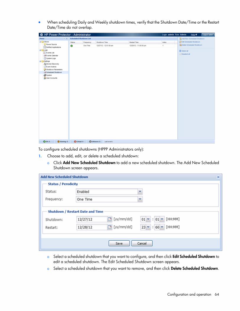
Configuration and operation 64
• When scheduling Daily and Weekly shutdown times, verify that the Shutdown Date/Time or the Restart Date/Time do not overlap.
To configure scheduled shutdowns (HPPP Administrators only):
1. Choose to add, edit, or delete a scheduled shutdown:
o Click Add New Scheduled Shutdown to add a new scheduled shutdown. The Add New Scheduled Shutdown screen appears.
o Select a scheduled shutdown that you want to configure, and then click Edit Scheduled Shutdown to
edit a scheduled shutdown. The Edit Scheduled Shutdown screen appears.
o Select a scheduled shutdown that you want to remove, and then click Delete Scheduled Shutdown.

Configuration and operation 65
2. In the Status field, select Enabled to activate the scheduled shutdown or Disabled to disable the scheduled shutdown.
3. In the Frequency field, select One Time, Every Day, or Every Week to set the occurrence of the scheduled shutdown.
4. In the Shutdown field:
a. Choose a date from the calendar for the scheduled shutdown to begin.
b. Select the hour for the scheduled shutdown to begin.
c. Select the minute for the scheduled shutdown to begin.
5. In the Restart field:
a. Choose a date from the calendar for the scheduled shutdown to restart.
If an Every Day shutdown periodicity is selected, the Restart Date and the Shutdown Date must be the same day, or the day after if the Restart Time is inferior to the Shutdown Time. The calendar selections are restricted accordingly.
b. Select the hour for the scheduled shutdown to restart.
c. Select the minute for the scheduled shutdown to restart.
6. Click Save. A warning message appears if scheduled shutdowns conflict, or if there is more than seven days between shutdown and restart of an Every Week periodicity.
Or, click Cancel to go back to the previous screen.
Click Help to view online help.

Configuration and operation 66
System screen Click System in the menu tree to display the System screen. This screen contains links to the license information and the HP website. An administrator can enter system contact information and configure language and automatic scan settings.
To view the license information, click About HP Power Protector.
To go to the HP website, click the website link.
To enter system contact information:
1. Double-click the System box, or click Edit system information. The Edit system information screen appears.
2. Enter the name of the contact person in the Contact field.
3. Enter the location of the contact person in the Location field.
4. Click Save.

Configuration and operation 67
To select the system language:
1. Double-click the Language settings box, or click Edit language. The Edit language screen appears.
2. Select the system display language from the Language pull-down menu.
3. Click Save.
To configure periodic scans for new devices:
1. Double-click the Scan settings box, or click Edit scan settings. The Edit scan settings screen appears.
Edit scan settings screen for HPPP Administrators
Edit scan settings screen for HPPP Clients
2. If you are configuring an HPPP Client, enter the default SNMP community name. The default value is
public.
3. Select the Automatic scan checkbox to enable automatic quick scans.
-or-
Clear the Automatic scan checkbox to disable automatic quick scans.
4. Click Save.
Click Help to view online help.

Configuration and operation 68
User Accounts screen Click User Accounts in the menu tree to display the User Accounts screen. This screen allows an administrator to add, edit, or remove user accounts.
HP Power Protector contains a default Administrator profile:
• User name—admin
• Password—admin
HP recommends that you change the default profile settings immediately after installation.
Create user accounts for each HPPP Administrator and Client. The HPPP Administrator is the instance of HP Power Protector that is directly connected to the UPS.
Users receive different privileges depending on the type of account you assign:
• User—A user can only view monitoring information and cannot configure settings to the system, UPSs, or applications.
• Admin—An admin has full access to all the screens and features and can configure settings to the system, UPSs, and applications.

Configuration and operation 69
There is no limit on the number of user accounts you can create. To create a user account:
1. Click Add user. The Add user screen appears.
2. Enter the user name in the Login field.
3. Enter the password in the Password field.
4. Re-enter the password in the Confirm password field.
5. Select the user type from the Profile pull-down menu (user or admin).
6. Click Save.
To edit a user account:
1. Double-click the user account you want to edit, or select the user account, and then click Edit user. The Edit user screen appears.
2. Enter the password in the Password field.
3. Re-enter the password in the Confirm password field.
4. Select the user type from the Profile pull-down menu (user or admin).
5. Click Save.
To remove a user account, select the user account you want to remove, and then click Remove user.
Click Help to view online help.
Views Menu options listed under Views include:
• Power Source ("Power Source screen" on page 70)
• Notified Applications ("Notified Applications screen" on page 86)

Configuration and operation 70
Power Source screen Click Power Source in the menu tree to display the Power Source screen. This screen allows you to monitor status information and data collected from the UPS that powers the server running HP Power Protector. The information refreshes every 10 seconds.
If redundant UPSs are configured, a Power Source screen is available for each UPS. To configure a redundant UPS, see "Device Discovery screen (on page 50)."
Six information boxes are available:
• Information and Status panel (on page 71)
• UPS Data panel (on page 74)
• Graph panel (on page 74)
• Power Scope panel (on page 75)
• Events panel (on page 78)
• Statistics panel (on page 79)
You can drag and drop the panels to appear in any order on the screen. Click the icon to expand a panel, or click the icon to collapse a panel.

Configuration and operation 71
To customize which panels are displayed:
1. Click the icon in the top, right corner (underneath the Logout button). The Select panels screen appears.
2. Select the checkbox for each panel you want to display.
3. Click Save.
Click Help to view online help.
Information and Status panel This panel displays the overall status of the UPS. The UPS information displayed in this panel depends on the model of the UPS and the configuration of either an HPPP Administrator or Client. The status information refreshes every 10 seconds.
HPPP Administrator
UPS information includes:
• UPS status icon—The current UPS status

Configuration and operation 72
Status icon Description
Normal operation
Alarm present Click the icon to display the UPS alarms.
UPS communication loss
• Description—The name of the UPS
• Firmware version—The UPS firmware version
• Nominal apparent power—The UPS nominal apparent power (in VA or KVA)
• Serial number—The UPS serial number
• Class—The communication protocol, for example, RS-232 device, USB device, or HPPP Administrator
• Link—A hyperlinked icon that directs you to the web interface for the HP UPS Network Module, if
installed, or the HPPP Administrator ( HTTP Connection, HTTPS Connection, or Communication Loss)
• Battery state—The current state of the UPS battery (Charging, Discharging, or Fault)
• Power source—The current source of UPS power (AC Power or Battery Power)
• Load level—The current UPS output load level
• Battery capacity—The remaining UPS battery capacity
• Battery runtime—The remaining backup time available from the UPS battery
• Entire UPS—The status of the UPS ( On, Off, Unknown, Internal Failure, On Automatic Bypass, Manual Bypass, Overload)
• Load segment—The load segment status ( On, Off, or Unknown)
HPPP Client
UPS information includes:

Configuration and operation 73
• UPS status icon—The current UPS status
Status icon Description
Normal operation
Alarm present Click the icon to display the UPS alarms.
UPS communication loss
• Description—The name of the UPS
• Firmware version—The UPS firmware version
• Nominal apparent power—The UPS nominal apparent power (in VA or KVA)
• IP address or DNS name—The IP address or DNS name of the UPS that powers the server running HP Power Protector
This information is only available for HPPP Clients.
• Serial number—The UPS serial number
• Class—The device type, for example, RS-232 device, USB device, or HPPP Administrator
• Link—A hyperlinked icon that directs you to the web interface for the HP UPS Network Module, if
installed, or the HPPP Administrator ( HTTP Connection, HTTPS Connection, or Communication Loss)
• Battery state—The current state of the UPS battery (Charging, Discharging, or Fault)
• Power source—The current source of UPS power (AC Power or Battery Power)
• Load level—The current UPS output load level
• Battery capacity—The remaining UPS battery capacity
• Battery runtime—The remaining backup time available from the UPS battery
• Entire UPS—The status of the UPS ( On, Off, Unknown, Internal Failure, On Automatic Bypass, Manual Bypass, Overload)
• Load segment—The load segment status ( On, Off, or Unknown)

Configuration and operation 74
UPS Data panel This panel displays input and output power information for the UPS. The data refreshes every 10 seconds.
The UPS information displayed in this panel varies depending on the UPS model. UPS data includes:
• Input
o Input frequency—The UPS input frequency
o Input voltage—The UPS input voltage
• Output
o Output frequency—The UPS output frequency
o Output voltage—The UPS output voltage
o Output current—The UPS output current
o Apparent power—The total UPS apparent power
o Active power—The total UPS active power
o Battery output voltage—The UPS battery output voltage
For a 3 phase UPS, data is displayed by phase. Hover your mouse over a 3 phase UPS data point for more information about the value.
Graph panel This panel displays a graphical representation of UPS data.
Hover your mouse over a data point to view the values of the graphed data.
Click the icon to zoom in to graph.

Configuration and operation 75
Up to six types of data can be plotted on the graph. To select the data you want to graph:
1. Click the icon. The Graph Settings screen appears.
2. Select up to six check boxes that correspond to the data you want to graph.
3. Select the amount of time the graph should reflect in the Time Scale pull-down menu. For example, if you select 12 hours, the graph shows 12 hours worth of collected data.
4. Click Save. The selected time scale displays at the top of the graph. The date and time of the oldest plotted data values displays in the bottom-left corner. The date and time of the most recent plotted data values displays in the bottom-right corner.
5. Click the date and time values in the bottom left and right corners to shift the displayed time windows back or forward.
Power Scope panel This panel displays the UPS electrical topology (Online UPS, Offline UPS, or Line Interactive UPS) and an animated graphical representation of the UPS operating mode, which shows the main UPS components and the electrical flow powering the load.
Hover your mouse over a diagram element to display UPS data details. UPS data is available for Normal mode, Battery mode, and Bypass mode. The available UPS data depends on the UPS range.

Configuration and operation 76
If communication with the UPS is lost, the diagram appears gray. Diagrams do not display for line-interactive UPSs.
The following table describes the possible diagrams.
Diagram UPS operating mode
UPS with automatic bypass
UPS without automatic bypass
The following table describes the possible diagram elements.
Diagram element Description
AC Normal Input
Green—In tolerance
Gray—Out of tolerance
AC Normal Flow
Yellow—AC to DC converter powered by normal AC
Gray—AC to DC converter not powered by normal AC
AC to DC Converter
Green—Powered
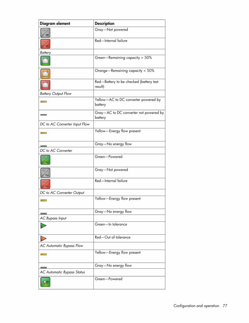
Configuration and operation 77
Diagram element Description
Gray—Not powered
Red—Internal failure
Battery
Green—Remaining capacity > 50%
Orange—Remaining capacity < 50%
Red—Battery to be checked (battery test result)
Battery Output Flow
Yellow—AC to DC converter powered by battery
Gray—AC to DC converter not powered by battery
DC to AC Converter Input Flow
Yellow—Energy flow present
Gray—No energy flow
DC to AC Converter
Green—Powered
Gray—Not powered
Red—Internal failure
DC to AC Converter Output
Yellow—Energy flow present
Gray—No energy flow
AC Bypass Input
Green—In tolerance
Red—Out of tolerance
AC Automatic Bypass Flow
Yellow—Energy flow present
Gray—No energy flow
AC Automatic Bypass Status
Green—Powered

Configuration and operation 78
Diagram element Description
Gray—Not powered
Red—Internal failure
AC Output Flow
Yellow—Energy flow present
Gray—No energy flow
AC Output
Green—Load protected
Red—Load not protected
Events panel This panel displays a list of UPS and application events.
Click the icon to zoom in to the event list.
Click a column header to sort the event list, or select Columns to customize the information displayed in the table. Available column options include:
• Status—A status icon indicating the severity of the event ( Normal, Warning, Critical,
or Communication Loss)
• Date—The date the event occurred
• Message—A description of the event
• Events that are acknowledged do not appear in the Events panel. For more information, see "Events List screen (on page 89)."

Configuration and operation 79
Statistics panel This panel displays a list of calculated statistics.
Statistics are calculated over the specified time period for the following categories:
• Estimated power consumption—The estimated amount of power consumed
• Average apparent power—The average apparent power
• Power lost count—The number of utility power failures that have occurred
• Cumulative power lost time—The total amount of time utility power has been out
• UPS overload—The number of times the UPS has detected an overload condition
To configure the range of time over which statistics are calculated:
1. Click the icon. The Days interval screen appears.
2. Enter the beginning date in the From field, or click the icon to select the date from a calendar.
3. Enter the ending date in the To field, or click the icon to select the date from a calendar.
4. Click Save. The configured interval displays at the top of the panel. The beginning date displays in the bottom-left corner. The ending date displays in the bottom-right corner.
5. Click the time date and time values in the bottom left and right corners to shift the displayed time windows back or forward, respectively.
To download a .csv file of the statistical data, click the icon.
Reconfiguring an HPPP power source If an HPPP Administrator power source needs to be changed, the following requirements must apply:
• The HPPP Administrator was previously configured to a power source.
• One or more HPPP Clients are currently connected to the HPPP Administrator.

Configuration and operation 80
HPPP Administrator configured with power source 1
HPPP Client configured with power source 1
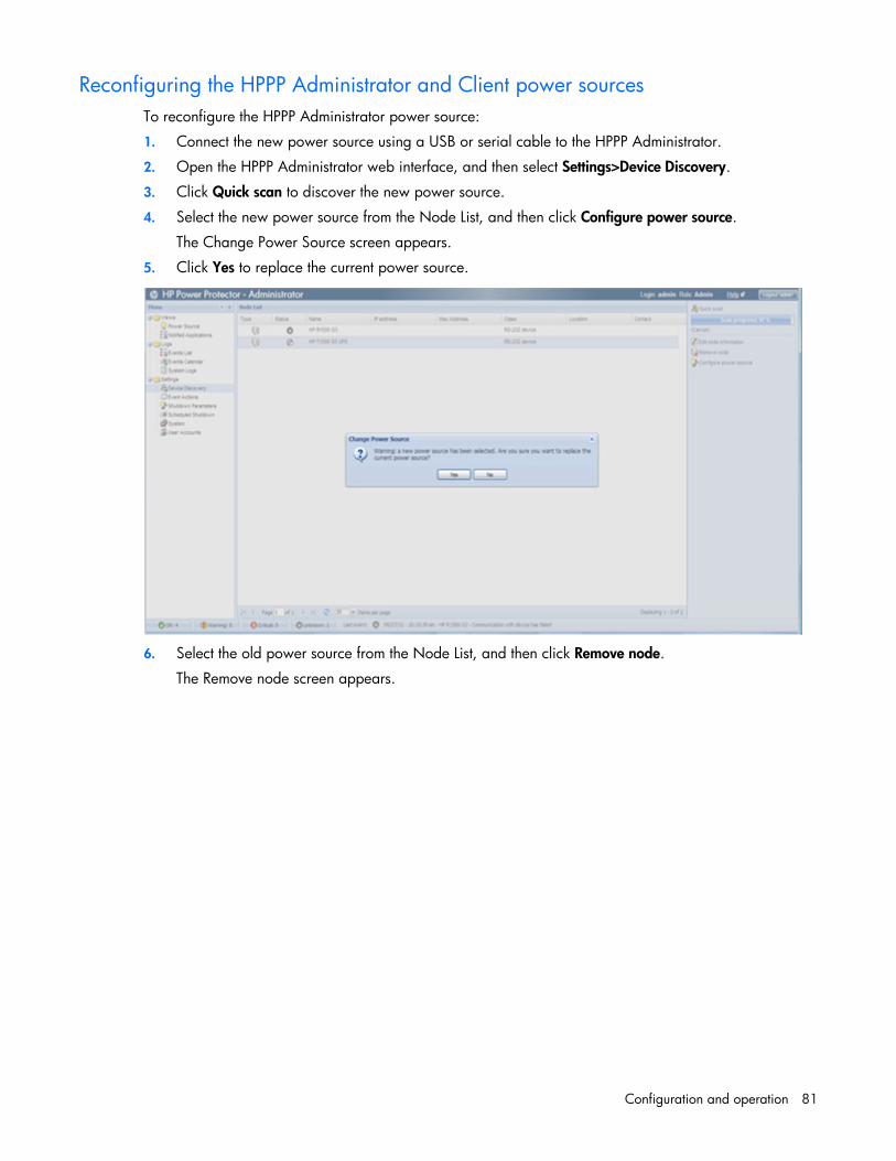
Configuration and operation 81
Reconfiguring the HPPP Administrator and Client power sources To reconfigure the HPPP Administrator power source:
1. Connect the new power source using a USB or serial cable to the HPPP Administrator.
2. Open the HPPP Administrator web interface, and then select Settings>Device Discovery.
3. Click Quick scan to discover the new power source.
4. Select the new power source from the Node List, and then click Configure power source.
The Change Power Source screen appears.
5. Click Yes to replace the current power source.
6. Select the old power source from the Node List, and then click Remove node.
The Remove node screen appears.
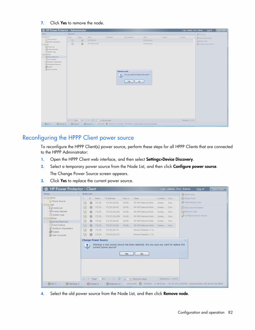
Configuration and operation 82
7. Click Yes to remove the node.
Reconfiguring the HPPP Client power source To reconfigure the HPPP Client(s) power source, perform these steps for all HPPP Clients that are connected to the HPPP Administrator:
1. Open the HPPP Client web interface, and then select Settings>Device Discovery.
2. Select a temporary power source from the Node List, and then click Configure power source.
The Change Power Source screen appears.
3. Click Yes to replace the current power source.
4. Select the old power source from the Node List, and then click Remove node.

Configuration and operation 83
The Remove node screen appears.
5. Click Yes to remove the node.
6. Click Quick scan to discover the new power source.
7. Select the new power source from the Node List, and then click Configure power source.
The Change Power Source screen appears.
8. Click Yes to replace the current power source.

Configuration and operation 84
Configuring the redundantly powered HPPP Client power source To configure the power source of redundantly powered HPPP Clients:
1. Open the HPPP Client web interface, and then select Settings>Device Discovery.
2. Select a redundant power source from the Node List, and then click Configure power source.
The Powersource Configuration screen appears.
3. Enter values in the Source #1 configuration fields, and then select the Is this machine protected by redundancy checkbox.
4. Enter values in the Source #2 configuration fields, and then click Save.
5. Select Settings>Shutdown Parameters, and then select Edit shutdown configuration.
6. Delete the value in the Shutdown initiated after (sec) field, and then click Save to set this parameter to None.
If the Shutdown initiated after (sec) field contains a value when in a redundant configuration, the Client uses this value to execute a graceful shutdown when one of the redundant UPSs goes On battery.

Configuration and operation 85
7. Click Save.
The HPPP Client is redundantly configured to two UPS power sources.
The image below shows the Power Source 1 Information and Status.

Configuration and operation 86
The image below shows the Power Source 2 Information and Status.
Notified Applications screen Click Notified Applications in the menu tree to display the Notified Applications screen. This screen is available to HPPP Administrators only and displays information about the HPPP Clients. If an HPPP Client has its power source configured as an HPPP Administrator, it automatically appears in the notified applications list of that HPPP Administrator.
Click Help to view online help.

Configuration and operation 87
Notified Applications Click a column header to sort the Notified Applications list. To customize the columns, select Columns, and then select the checkboxes that correspond to the data you want to include. Available column options include:
• Type—An icon indicating the application type
• Status—An icon indicating the current status of the communication between the Administrator and the
Client ( Normal or Communication Loss)
• IP address—The IP address of the application
• Name—The name of the associated HPPP Client
• Description—A description of the application
• Version—The version of the application
• Runtime to empty—The remaining runtime of the power source in the case of a power failure
• Shutdown initiated after—The amount of time that elapses between a power failure and the initiation of the shutdown sequence
This value is configured in the HPPP Client and displays in this column.
• Estimated runtime to shutdown—The amount of runtime available before the associated HPPP Client shutdown sequence initiates
This value is configured in the HPPP Client and displays in this column.
• OS shutdown time—The amount of time required to shut down the operating system
• Shutdown diagram—A chronological illustration of the shutdown sequence for the associated HPPP Client
The diagrams present a visual representation of the shutdown sequencing between the different agents.
o The total width of the diagram represents the remaining runtime of the power source in the case of a power failure.
o The green area represents the amount of runtime available before the agent shutdown sequence initiates.
o The orange area represents the amount of time required to shut down the agent.
o The red area represents the amount of time the agent is powered off.
• Power source shutoff—Indicates if the load segment is configured to shut off after HPPP Clients shut down during a power failure
• Power source—The name of the UPS powering the device
• Load segment—The associated UPS load segment
• User type—A user-defined value that can be used to sort devices
The user type can be specified by editing a device on the Device Discovery screen (on page 50).
• User note—A user-defined message that can be used to sort devices
A user note can be entered by editing a device on the Device Discovery screen (on page 50).
• Access—The status of the HPPP Client’s login credentials to the HPPP Administrator (must be an administrator level user name and password)

Configuration and operation 88
• Link—A link to the web interface for the associated HPPP Client ( HTTP Connection, HTTPS
Connection, or Communication Loss)
To manipulate the entries in the Notified Applications list:
1. Click the icon.
2. Do one of the following:
o Search for an application using a keyword.
o Edit information for an application.
To manually remove an application from the Notified Applications list, see "Device Discovery screen (on page 50)."
Selection View Select an entry in the Notified Applications list to view detailed information panels in the Selection View. Available panels include:
• Information—Displays basic information about the selected application
• Status—Displays status information for the selected application
• Events—Displays the list of events for the selected application
You can drag and drop the panels to appear in any order on the screen. Click the icon to expand a panel, or click the icon to collapse a panel.
To customize which panels are displayed:
1. Click the icon. The Select panels screen appears.
2. Select the checkbox for each panel you want to display.
3. Click Save.
Click the or icon to show or hide the Selection View.

Data logs 89
Data logs
Logs Menu options listed under Logs include:
• Events List ("Events List screen" on page 89)
• Events Calendar ("Events Calendar screen" on page 91)
• System Log ("System Log screen" on page 92)
Events List screen Click Events List in the menu tree to display the Events List screen. This screen displays a list of all UPS events.
Click an event severity button on the bottom toolbar to filter the Events List by the corresponding severity. Only unacknowledged events display.
Click a column header to sort the complete Event List, or select Columns to customize the information displayed in the table. Available column options include:
• Status—A status icon indicating the severity of the event ( Normal, Warning, Critical,
or Communication Loss)
• Date—The date the event occurred
• Name—The name of the event
• Message—A description of the event
• Ack—An icon indicates if the event is acknowledged

Data logs 90
Acknowledged events remain viewable in the Event List, but no longer appears on the Power Source screen Events panel (on page 78). Acknowledged events are not counted in the severity totals included on the buttons on the bottom toolbar.
To navigate through the Events List:
• Click to go to the first page in the list.
• Click to go to the previous page in the list.
• Click to go to the next page in the list.
• Click to go to the last page in the list.
• Click to refresh the list.
• Select the number of events to display on each page in the Items per page pull-down menu. Available options are 25, 50, 75, and 100.
To select events in the list:
• Click an event.
• Hold down the Shift key and select a range of events.
• Hold down the Ctrl key and select multiple events.
• Click Select All to select all events.
• Click Deselect All to clear all selected events.
To acknowledge events:
• Select the events you want to acknowledge, and then click Acknowledge selected events.
• Click Acknowledge all events to acknowledge all events in the list.
To download a .csv file of the Events List, click Export logs.
Click Help to view online help.

Data logs 91
Events Calendar screen Click Events Calendar in the menu tree to display the Events Calendar screen. This screen displays a calendar representation all UPS and application events. Each entry represents one week, and each column represents one day.
Click Help to view online help.
Events Calendar Click the Week column header to sort the entries by week. Icons appear in the calendar and represent the
types of events that occurred each day ( Normal, Warning, Critical, or Communication Loss).
When days are selected, the events and statistics that appear in the Selection View panels update to reflect the activity for the selected days. The selected days display at the top of each panel. To select days in the calendar:
• Click a day.
• Hold down the Shift key and click multiple days.
• Click the icon, and then select Deselect all to clear all selected days.
To configure a range of time over which events and statistics appear in the Selection View panels:
1. Click the icon, and then select Select days interval. The Days interval screen appears.
2. Enter the beginning date in the From field, or click the icon to select the date from a calendar.
3. Enter the ending date in the To field, or click the icon to select the date from a calendar.

Data logs 92
4. Click Save. The configured interval displays at the top of each panel.
Selection View Two panels appear in the Selection View:
• Events—Displays the list of events for the selected days
To acknowledge selected events, click the icon.
• Statistics—Displays statistical data for the selected days
To download a .csv file of the statistical data, click the icon.
Click the icon to expand a panel, or click the icon to collapse a panel.
Click the or icon to show or hide the Selection View.
System Log screen Click System Log in the menu tree to display the System Log screen. This screen displays a list of all system events.
Click a column header to sort the System Logs. Available column options include:
• Date—The date the event occurred
• Type—A status icon indicating the severity of the event ( Information or Error)
• Message—A description of the event
To navigate through the System Logs:
• Click to go to the first page in the list.
• Click to go to the previous page in the list.
• Click to go to the next page in the list.

Data logs 93
• Click to go to the last page in the list.
• Click to refresh the list.
• Select the number of events to display on each page in the Items per page pull-down menu. Available options are 25, 50, 75, and 100.
To filter entries by type:
• Click View system errors to only display error entries.
• Click View system infos to only display informational entries.
• Click View all to display error and informational entries.
To view details of a log entry, double-click the entry, or:
1. Select the entry.
2. Click Detail system log.
To download a .csv file of the System Logs, click Export logs.
To clear the System Logs, click Purge system logs.
Click Help to view online help.

Troubleshooting 94
Troubleshooting
Cannot access HPPP after installation Possible Cause: Other web servers or web-based applications are running on the same port.
Action:
1. Be sure to include this port number when browsing to HPPP. For example: http://hostname:4679 https://hostname:4680
where hostname is either a machine name or an IP address.
2. Be sure that no other web servers or web-based applications are running on the same port.
3. Be sure the proper firewall settings are enabled on the server running HPPP.
4. Restart the HPPP service.
Cannot configure an HPPP Client power source Symptom: After configuring the power source, the power source status icon does not illuminate green.
Possible cause: The edit node information was updated before configuring the power source.
Action:
1. Remove the power source node.
2. Select Quick Scan to discover the power source.
3. Configure the power source.
4. Edit the node.
HPPP Clients do not appear on the HPPP Administrator Notified Application screen
Action: Be sure that the proper firewall settings are enabled on both the HPPP Administrator and Client servers to ensure proper communication.
HPPP sends invalid links in email notifications on Linux platforms
Possible Cause: The Linux OS host information was not properly updated, so the following invalid link is displayed in HPPP generated emails:
http://hostname

Troubleshooting 95
Action:
1. Navigate to /etc and open the file named host with a text editor.
2. Update the information in the file to reflect updated IP address, Email, and User information. For example: 172.25.234.200, [email protected], root
3. Reboot the computer.
Error occurs when starting the HPPP service on RHEL IA64
Symptom: When installing HPPP on RHEL IA64 the following error message appears on the terminal: Unable to init module ‘bin/musb.so’ (libunwind.so.7 cannot open shared object file: No such file or directory)
Possible cause: The RHEL IA64 operating system installation is missing the following dependency: Libunwind-0.98.5-5.el5.ia64.rpm
Action:
1. Insert the Redhat operating system CD or DVD into the DVD-ROM drive.
2. Locate and then install the library:
libunwind-0.98.5-5.el5.ia64.rpm.
3. Install HPPP.
Invalid IP address Possible Cause: IP addresses are not checked for validity.
Action: Verify that the IP address entered is valid.
Links in emails do not work correctly for Linux Action: Update the /etc/hosts file with the correct host name or IP address.
Low battery warning is displayed Action: Plug the UPS into an AC grounded outlet for at least 24 hours to charge the batteries, and then test the batteries. Replace the batteries if necessary.
No power Action: Verify that the UPS is connected to a working outlet and that the UPS is powered up.

Troubleshooting 96
Notification window is not available on SLES 10 Symptom: The notification window does not appear on SLES 10.
Possible cause: This version of the operating system does not contain the required GTK 2.10 dependency for notification functionality.
Action: Update to a SLES operating system that supports GTK 2.10.
On battery alarm Action: The UPS continues to run on battery power until the battery is completely discharged (or until utility power is restored), unless the shutdown parameters specify to power down all of the UPS load segments.
On boost alarm Possible Cause: The input voltage is too low for the UPS. The UPS boosts the voltage up to acceptable limits.
Action: For information on Boost mode, refer to the UPS documentation.
On buck alarm Possible Cause: The input voltage is too high for the UPS. The UPS bucks the voltage down to acceptable limits.
Action: For information on Buck mode, refer to the UPS documentation.
Overload alarm Possible Cause: The device load has exceeded the UPS power rating.
Action: Verify all equipment is drawing within the rated requirements. If necessary, reduce the equipment connected to the UPS. The UPS might need to be reset.
Receiving a security error Symptom: Security error: Domain Name mismatch message when trying to browse with SSL.
Possible Cause: The IP address or server name has changed.
Action: Stop the service, delete the certificate file, and restart the service.
Servers running Windows Server® 2003 do not restart
Symptom: Servers running Windows Server® 2003 do not restart upon power restoration following a power fail shutdown.
Possible Cause: This is a known Windows Server® 2003 behavior on some servers.

Troubleshooting 97
Action: Refer to the Microsoft® Knowledge Base article 819760.
Task Bar menu does not clear Symptom: The task bar menu does not clear when clicking off the menu onto the Windows® desktop.
Possible Cause: This is a known Windows® behavior.
Action: Start another application or open a new window, and the issue disappears.
Unable to discover a UPS Action:
• Verify that the UPS is connected to the correct communications port (COM1, COM2, and so on).
• Verify that no other software or processes are accessing the communications port to which the UPS is attached.
• Verify that you are using the communications cable that came with the UPS.
• Verify that resources for the selected communications port (such as I/O port or IRQ) are not shared with other devices.
• Try a different communications port.
• Verify that the HPPP Administrator and Clients have permanent IP addresses.
UPS is not detected in RHEL5 when attached to serial ports other than COM 1
Possible Cause: The IRQ in the operating system and RBSU differ.
Action: Manually change the serial port parameters in the operating system using the following command with the same IRQ and base address that is assigned to the serial port in RBSU:
# setserial /dev/ttyS1 port 0x02f8, irq 3
This is the only way that communication will occur.
Utility alarm Possible Cause: The utility input voltage is repeatedly outside the UPS operating range.
Action:
1. Check the HPPP event log files to obtain specific error information.
2. Check the input voltage and reconfigure the UPS. For more information about configuring the UPS, see the UPS documentation.
-or-
Contact a qualified electrician to verify that the utility power is suitable for the UPS.
3. Rediscover the UPS so that HPPP reads the new nominal voltage and shows the correct limits on the graphs.

Alert messages 98
Alert messages
UPS alarms • Emergency Power Off
• Emergency Power Off Cleared
• UPS ABM Controller Disabled
• UPS ABM Controller Enabled
• UPS AC Module Failure
• UPS AC Module Failure Cleared
• UPS Auto Bypass Overload
• UPS Auto Bypass Overload Cleared
• UPS Battery Charger Failure
• UPS Battery Charger Failure Cleared
• UPS Battery Discharged
• UPS Battery Discharged Cleared
• UPS Battery Disconnected
• UPS Battery Disconnected Cleared
• UPS Battery Low
• UPS Battery Low Cleared
• UPS Battery Over Voltage
• UPS Battery Over Voltage Cleared
• UPS Battery Test Failure
• UPS Battery Test Failure Cleared
• UPS Bypass AC Phase Out of Range
• UPS Bypass AC Phase Out of Range Cleared
• UPS Bypass Frequency Out Of Range
• UPS Bypass Frequency Out Of Range Cleared
• UPS Bypass Not Available
• UPS Bypass Not Available Cleared
• UPS Bypass Voltage Out Of Range
• UPS Bypass Voltage Out Of Range Cleared
• UPS Client Communication Lost

Alert messages 99
• UPS Client Communication Restored
• UPS DC Bus High Negative Voltage
• UPS DC Bus High Negative Voltage Cleared
• UPS DC Bus High Positive Voltage
• UPS DC Bus High Positive Voltage Cleared
• UPS DC Bus Low Negative Voltage
• UPS DC Bus Low Negative Voltage Cleared
• UPS DC Bus Low Positive Voltage
• UPS DC Bus Low Positive Voltage Cleared
• UPS Fan Failure
• UPS Fan Failure Cleared
• UPS In High Efficiency Mode
• UPS Input AC Not Present
• UPS Input AC Not Present Cleared
• UPS Input AC Over Voltage
• UPS Input AC Over Voltage Cleared
• UPS Input AC Under Voltage
• UPS Input AC Under Voltage Cleared
• UPS Input Frequency Out Of Range
• UPS Input Frequency Out Of Range Cleared
• UPS Internal Configuration Failure
• UPS Internal Configuration Failure Cleared
• UPS Internal Failure
• UPS Internal Failure Cleared
• UPS Inverter Failure
• UPS Inverter Failure Cleared
• UPS Inverter Over Voltage
• UPS Inverter Over Voltage Cleared
• UPS Inverter Overload
• UPS Inverter Overload Cleared
• UPS Inverter Under Voltage
• UPS Inverter Under Voltage
• UPS Load Segment 1 Is Off
• UPS Load Segment 1 Is On
• UPS Load Segment 2 Is Off
• UPS Load Segment 2 Is On

Alert messages 100
• UPS Load Segment 3 Is Off
• UPS Load Segment 3 Is On
• UPS On Auto Bypass
• UPS On Auto Bypass Cleared
• UPS On Battery
• UPS On Battery Cleared
• UPS On Boost
• UPS On Boost Cleared
• UPS On Buck
• UPS On Buck Cleared
• UPS On Manual Bypass
• UPS On Manual Bypass Cleared
• UPS Output Is Off
• UPS Output Is On
• UPS Output Overload
• UPS Output Overload Cleared
• UPS Output Overload Level 1
• UPS Output Overload Level 1 Cleared
• UPS Output Overload Level 2
• UPS Output Overload Level 2 Cleared
• UPS Output Short Circuit
• UPS Output Short Circuit Cleared
• UPS Over Temperature
• UPS Over Temperature Cleared
• UPS Rectifier Failure
• UPS Rectifier Failure Cleared
• UPS Rectifier Overload
• UPS Rectifier Overload Cleared
• UPS Redundant Communication Lost
• UPS Redundant Communication Restored
• UPS Shutdown Imminent
• UPS Shutdown Imminent Cleared
• UPS Shutdown in {time}
• UPS Shutdown Pending
• UPS Single Wave Load Fault
• UPS Single Wave Load Fault Cleared

Alert messages 101
• UPS Site Wiring Fault
• UPS Site Wiring Fault Cleared

Security considerations 102
Security considerations
Security considerations overview HPPP has browser accessibility.
To better ensure the security of HPPP and the devices it manages, consider the following topics in accordance with your organization's security policies and the environment in which HPPP will operate:
• Remote access to HPPP requires a user account. Logging in requires the use of a user name and password, which should be kept properly secured.
• Each account can be given different access levels, providing different capabilities. Ensure that the appropriate access level is granted to users.
• Enforce a strong password policy for all users.
• Browsing to HPPP can be done using SSL, which encrypts the data between the browser and HPPP. HPPP is supported by a 128-bit encryption level. SSL also provides authentication of HPPP by means of its digital certificate. Securely importing this certificate must be done to ensure the identification of HPPP.
• Use a custom SSL certificate that is certified by a third-party SSL authority.
• Keeping HPPP to an internal network is preferred.

Firewall configuration 103
Firewall configuration
Configuring the firewall on Windows operating systems
NOTE: For other operating systems, see the operating system documents on enabling or disabling ports on the firewall.
Windows Firewall blocks most communication through unused IP ports. This prevents a server with the HPPP Administrator or Client installed from using the ports to communicate with the device. Be sure the following ports are open on both the Administrator and the Clients:
• 4679/TCP (HTTP)
• 4680/TCP (HTTPS)
• 4679/UDP and TCP (Client)
• 4680/UDP and TCP (Client)
• 5000/TCP (Alarms)
• 5001/TCP (Alarms)

Firewall configuration 104
To configure the Windows XP with Service Pack 2 Firewall to make an exception for ports 4679, 4680, 5000, and 5001:
1. Click Start, select Control Panel, and then double-click Network Connections. The Network Connections screen appears.
2. Right-click the network connection where you are configuring the firewall, and then select Properties.
The Properties screen appears.
3. Click the Advanced tab.
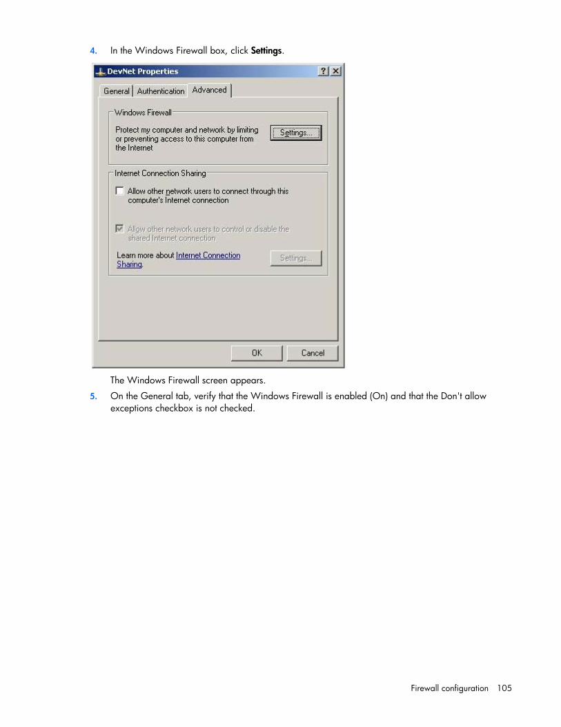
Firewall configuration 105
4. In the Windows Firewall box, click Settings.
The Windows Firewall screen appears.
5. On the General tab, verify that the Windows Firewall is enabled (On) and that the Don't allow exceptions checkbox is not checked.

Firewall configuration 106
6. Click OK.
7. On the network Properties screen, click the Exceptions tab.
8. Be sure that the File and Printer Sharing check box is selected.

Firewall configuration 107
9. Click Add Port to allow communication through ports 4679, 4680, 5000, and 5001.
The Add a Port screen appears.
10. Enter a name for the HPPP Client port in the Name field.
11. Enter 4679, 4680, 5000, or 5001 in the port number field.
12. Select the appropriate radio button.
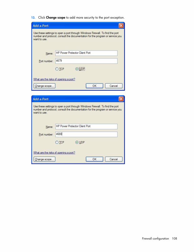
Firewall configuration 108
13. Click Change scope to add more security to the port exception.

Firewall configuration 109
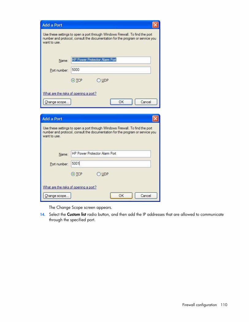
Firewall configuration 110
The Change Scope screen appears.
14. Select the Custom list radio button, and then add the IP addresses that are allowed to communicate through the specified port.

Firewall configuration 111
15. Click OK to save the scope settings.
16. On the Edit a Port screen, click OK to finish adding the exception port.
The Windows Firewall screen displays the newly added HPPP Client port.
17. Click OK.
NOTE: Software that helps to protect your computer and blocks access on the network, such as Windows® Defender or firewalls, needs to be reconfigured.

Firewall configuration 112

Installing on a virtual operating system 113
Installing on a virtual operating system
Installing HPPP on Microsoft Hyper-V architecture This section guides you through the installation of HPPP on Microsoft Hyper-V architecture. Using HPPP allows continuity of the electrical power supply to the internal power system.
Item Description
1 Physical machine with Hyper-V Manager, Hyper-V Server R1, R2 and HPPP
2 UPS with an HP UPS Network Module
Configuring Microsoft Hyper-V Manager / Hyper-V Server R1/R2 Configure the physical machine to allow automatic operating system boot on start-up in the BIOS. For more information, see the hardware documentation. You might have to activate Virtualization Technology Enabled, in the BIOS, to run Hyper-V. To activate Virtualization Technology Enabled, go to CPU Information>Virtualization Technology>Enabled.
To enable a graceful shutdown of the Virtual Machines, install and configure the Guest Component Service on each Virtual Machine. To install the Guest Component Service:
1. Open the Hyper-V console, and then start the Virtual Machine.
2. Select the Action tab, and then select Insert the disk integration services.
3. Install the service, and then verify that the software is available in Control Panel>Add/Remove Programs of the Virtual Machine.
To configure the Guest Component Service:
1. Open they Hyper-V console, and then right click on the Virtual Machine where the service was installed.
2. Select Settings>Integration Services.
3. Select the Operating System shutdown checkbox.

Installing on a virtual operating system 114
4. Click Apply, and then click OK.
To set each Virtual Machine to automatically boot when Microsoft Hyper-V starts-up:
1. From Hyper-V manager, select the Virtual Machine list.
2. Select the Virtual Machine.
3. Select Parameters>Manage>Automatic Start Action.
4. Select the appropriate parameters for the Virtual Machine that coincide with the start rules of the specific application.

Installing on a virtual operating system 115
5. Click OK.
To set each Virtual Machine to automatically gracefully shutdown when Microsoft Hyper-V stops:
1. From Hyper-V manager, select the Virtual Machine list.
2. Select the Virtual Machine.
3. Select Parameters>Management>Automatic Stop Actions.
4. Select the appropriate parameters for the Virtual Machine that coincide with the shutdown rules of the specific application.

Installing on a virtual operating system 116
5. Click OK.
NOTE: With Windows Hyper-V Server, this configuration is done remotely. Microsoft Management Console (MMC) is installed on a remote computer running Windows 2008 Server or Vista SP1.
Hardware architecture For the HPPP installation prerequisites, see "System requirements (on page 18)."
For a list of compatible UPSs, see the HP website (http://www.hp.com/go/rackandpower).
Network architecture All hardware components must have an operational network configuration that allows free communication.

Installing on a virtual operating system 117
The HPPP specific ports must be authorized within the firewall of the main operating system. For more information, see "Configuring the firewall on Windows ("Configuring the firewall on Windows operating systems" on page 103)."
To configure the network parameters of the main operating system, see the operating system user manual.
Installing HPPP on Hyper-V Server R1/R2 and Windows Server 2008 R2 (Hyper-V Manager)
To install HPPP on Hyper-V Server R1/R2 and Windows Server 2008 R2:
1. Download the latest version of the HPPP Windows package from the HP website (http://www.hp.com/go/rackandpower).
2. Copy the package to the system.
3. Execute the package from the DOS Windows command, and then go to the directory where you placed HPPP.
To start the installer in graphical mode, enter: hppp_win_x_xx_xxx.exe –install or start hppp_win_x_xx_xxx.exe
To start the installer in silent mode, enter: hppp_win_x_xx_xxx.exe –install –silent
After the installation is complete, you can access the HPPP web interface.
Alarm reception When there is a UPS status change, a notification window displays the alarms.
Using HPPP with Hyper-V Server R1/R2 or Hyper-V Manager After the HPPP installation, follow these steps to use HPPP:
1. To locally access Hyper-V Manager on Windows 2008, select Start>Programs>HP>Power Protector>Open HP Power Protectors from the system where HPPP is installed.
To remotely access Hyper-V Manager on Windows 2008, enter one of following URLs in a web browser: o https://<name or IP address of computer hosting HPPP>:4680/ o http://<name or IP address of computer hosting HPPP>:4679/
2. In SSL mode, click Yes to accept the certificate.
3. Read the license agreement, and then click Accept.
4. Enter the login name and password (admin/admin), and then click Login.
5. Select the HPPP Client component, and then click Save.
A Quick scan runs and discovers the networked UPSs.
6. To assign a networked UPS as the power source, select the node, and then click Configure Power Source. The Status icon illuminates green.
The discovered nodes are displayed in Settings>Device Discovery.

Installing on a virtual operating system 118
For the other nodes, perform the discovery based on IP address ranges. Using the Range Scan operation, the nodes that are outside of the network segment and the nodes that are not compatible with the Quick scan feature are discovered.
7. Select Settings>Shutdown Parameters to assign the IP address of the UPS that powers the local computer.
8. Select Settings>User Accounts to assign access rights through by login and password.
9. (optional) Select Views>Power Source to supervise the current state of the UPS that powers the server running HPPP.
10. Select Events>Event List to view the device events.
Uninstalling HPPP To uninstall HPPP from the DOS Window, go to the directory where you installed the HPPP. The default installation path is C:\Program Files\HP\PowerProtector.
To uninstall in graphical mode, enter:
hppp_win_x_xx_xxx.exe –uninstall
To uninstall in silent mode, enter: hppp_win_x_xx_xxx.exe –uninstall –silent
Installing HPPP on VMWare ESX architecture This section guides you through the installation of HPPP on VMware ESX architecture. Using HPPP allows continuity of the electrical power supply to the your internal power system.
Item Description
1 Virtual Machine
2 Virtual Machine

Installing on a virtual operating system 119
Item Description
3 Virtual Machine
4 Physical machine with VMware ESX and HPPP
5 UPS with an HP UPS Network Module
Configuring VMware ESX Server 4.0 To enable a graceful shutdown of the Virtual Machines, install VMware Tools on each Virtual Machine.
To allow interactions between the physical and virtual machines, install VMware Tools on each virtual machine. For more information, see the VMware ESX Server documentation.
Configure the physical machine to allow automatic operating system boot on start-up in the BIOS. For more information, see the hardware documentation.
To set each Virtual Machine to automatically boot when VMware starts-up:
1. From the Virtual Infrastructure Client, select Virtual machine startup / shutdown menu>Configuration>Properties>Start and stop Virtual Machines with the system, and then click Enable.
2. Define the Startup Order of the Virtual Machines.
o Start and Stop Virtual Machines with the system—Enabled
o Default Startup Delay—x Seconds
o Default Shutdown Delay—x Seconds

Installing on a virtual operating system 120
o Startup Order—Automatic Startup
Hardware architecture For the HPPP installation prerequisites, see "System requirements (on page 18)."
For a list of compatible UPSs, see the HP website (http://www.hp.com/go/rackandpower).
Network architecture All hardware components must have an operational network configuration that allows free communication.
The HPPP specific ports must be authorized within the firewall of the main operating system. For more information, see "Configuring the firewall on Windows ("Configuring the firewall on Windows operating systems" on page 103)."
To configure the network parameters of the main operating system, see the operating system user manual.
Installing HPPP on VMware ESX Server 4.0 To install HPPP on VMware ESX Server 4.0:
1. Download the latest version of HPPP from the HP website (http://www.hp.com/go/rackandpower). The ESX Server is automatically detected, and a shutdown command script is generated. The shutdown.sh script is installed in <installation folder>/bin, by default /usr/local/HP/PowerProtector/bin.
2. With an SCP Client, upload the package to the VMware ESX environment. For example, in the Windows environment: WinSCP.

Installing on a virtual operating system 121
3. Connect to the VMware server with SSH. For example, in the Windows environment: Putty. You must have corresponding rights to execute and install programs on VMware ESX.
4. When executing the installer, the following error message might appear:
./HPPP_linux_x_y_z-i386: cannot execute binary file.
Copy the installation source to the local drive of the ESX server.
5. Install HPPP by entering: ./HPPP_linux_x_y_z-i386-install –silent
6. Connect to HPPP by launching a supported web browser. A browser window appears.
7. In the URL field, enter one of the following: http://<@IP-or-name-of-ESX>:4679 https://<@ IP-or-name-of-ESX>:4680
The HPPP interface appears.
Using HPPP with VMware ESX Server 4.0 After the HPPP installation is complete, follow these steps to use HPPP:
1. From a remote machine, launch a supported web browser. A browser window appears.
2. In the URL field, enter one of the following: https://<name or IP address of Server hosting HPPP>:4680/ http://<name or IP address of Server hosting HPPP>:4679/
3. In SSL mode, click Yes to accept the certificate.
4. Enter the login name and password (admin/admin), and then click Login.
5. Start the application. A Quick scan runs and discovers the networked UPSs.
6. To assign a networked UPS as the power source, select the node, and then click Set as Power Source. The Status icon illuminates green.
The discovered nodes are displayed in Settings>Device Discovery.
For the other nodes, perform the discovery based on IP address ranges. Using the Range Scan operation, the nodes that are outside of the network segment and the nodes that are not compatible with the Quick scan feature are discovered.
7. Select Settings>Shutdown Parameters to assign the IP address of the UPS that powers the local computer.
8. Select Settings>User Accounts to assign the access rights by login and password.
9. (optional) Select Views>Power Source to supervise the current state of the UPS that powers the server running HPPP.
10. Select Events>Event List to view the device events.

Installing on a virtual operating system 122
Installing HPPP on VMware ESXi architecture This section guides you through the installation and configuration of HPPP on VMware ESXi. Using HPPP allows continuity of the electrical power supply to your internal power system.
Item Description
1 Virtual Machine
2 Virtual Machine
3 VIMA/vMA machine with HPPP
4 Physical machine with VMware ESXi boot loader
5 UPS with an HP UPS Network Module
Prerequisites Verify the following applications are installed:
• VMware ESXi Server Machine
• VMware Infrastructure Management Assistant VIMA 1.0 or vSphere Management Assistant (vMA 5.X) installed as guest
• vSphere Client installed on a different machine for VMware ESXi Server configuration
• HPPP for Linux
• SSH client for installation and configuration
• SCP Client to upload packages to VIMA/vMA
• Tools installed on each Virtual Machine

Installing on a virtual operating system 123
Installing VIMA/vMA on ESXi host machines For more information about downloading and installing VIMA or vMA on ESXi host machines, see the VMware website (http://www.vmware.com).
Configuring VMware ESXi Server To allow interactions between the physical and virtual machines, install VMware Tools on each virtual machine. For more information, see the VMware ESXi Server documentation.
Configure the physical machine to allow automatic operating system boot on start-up in the BIOS. For more information, see the hardware documentation. You can configure the automatic startup and shutdown properties of guest operating systems as per requirement. For HPPP to work properly, VIMA/vMA needs to be configured as:
• Automatic Shutdown of VIMA/vMA when ESXi host is powering down
• Automatic Startup of VIMA/vMA when ESXi host is starting up
To set each Virtual Machine to automatically boot when VMware starts-up:
1. From the Virtual Infrastructure Client interface, select the top-most ESXi host server from the tree hierarchy on the left side of the screen.
2. Select Virtual machine startup / shutdown menu>Configuration>Properties.
The Virtual Machine Startup and Shutdown screen appears.
3. Select the VIMA/vMA guest machine, and then click Edit.

Installing on a virtual operating system 124
The Virtual Machine AutoStart Settings screen appears.
4. In the Startup Settings section, select Use specified settings, and then set the Startup Delay to 120
seconds.
5. In the Shutdown Settings section, select Use specified settings, and then set the Shutdown Delay to120 seconds.
6. Click OK.
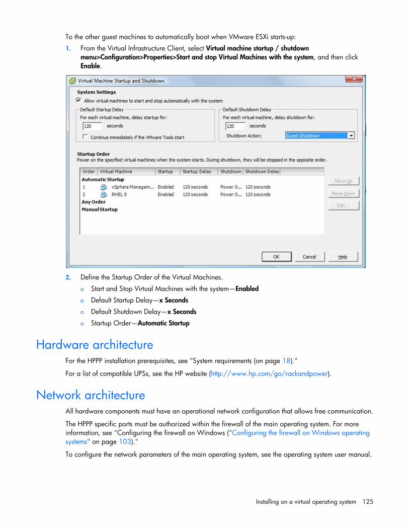
Installing on a virtual operating system 125
To the other guest machines to automatically boot when VMware ESXi starts-up:
1. From the Virtual Infrastructure Client, select Virtual machine startup / shutdown menu>Configuration>Properties>Start and stop Virtual Machines with the system, and then click Enable.
2. Define the Startup Order of the Virtual Machines.
o Start and Stop Virtual Machines with the system—Enabled
o Default Startup Delay—x Seconds
o Default Shutdown Delay—x Seconds
o Startup Order—Automatic Startup
Hardware architecture For the HPPP installation prerequisites, see "System requirements (on page 18)."
For a list of compatible UPSs, see the HP website (http://www.hp.com/go/rackandpower).
Network architecture All hardware components must have an operational network configuration that allows free communication.
The HPPP specific ports must be authorized within the firewall of the main operating system. For more information, see "Configuring the firewall on Windows ("Configuring the firewall on Windows operating systems" on page 103)."
To configure the network parameters of the main operating system, see the operating system user manual.

Installing on a virtual operating system 126
Installing HPPP on VMware ESXi Server 5.X To install HPPP on VMware ESXi Server 5.X:
1. Download the latest version of HPPP from the HP website (http://www.hp.com/go/rackandpower). The ESXi Server is automatically detected, and a shutdown command script is generated. The shutdown ESXi perl script is installed in <installation folder>/bin/, by default /usr/local/HP/PowerProtector/bin/.
2. Upload the package to the VIMA/vMA environment with an SCP Client.
3. Connect to the vMA with SSH. You must have corresponding rights to execute and install programs on VIMA/vMA. For more information, see the VMware documentation.
4. If you are not the root user when executing the installer, the following error message might appear:
Error: Can't create transaction lock.
Enter sudo -s to get a root console, and then run the installer again.
5. Install HPPP by entering: [vma ~]$ rpm -i hppp-linux-x.xx.xxx-x.x86_64.rpm
6. Connect to HPPP by launching a supported web browser. A browser window appears.
7. In the URL field, enter one of the following: http://<@IP-or-name-of-vMA>:4679/ https://<@ IP-or-name-of-vMA>:4680/
The HPPP interface appears.
Using HPPP with VMware ESXi Server 5.X After the HPPP installation is complete, follow these steps to use HPPP:
1. From a remote machine, launch a supported web browser. A browser window appears.
2. In the URL field, enter one of the following: https://<name or IP address of vMA hosting HPPP>:4680/ http://<name or IP address of vMA hosting HPPP>:4679/
3. In SSL mode, click Yes to accept the certificate.
4. Enter the login name and password (admin/admin), and then click Login.
5. Start the application. A Quick scan runs and discovers the networked UPSs.
6. To assign a networked UPS as the power source, select the node, and then click Configure Power Source. The Status icon illuminates green.
The discovered nodes are displayed in Settings>Device Discovery.
For the other nodes, perform the discovery based on IP address ranges. Using the Range Scan operation, the nodes that are outside of the network segment, and the nodes that are not compatible with the Quick scan feature are discovered.
7. Select Settings>User Accounts to assign the access rights by login and password.
8. Select Edit the shutdown configuration, set the Shutdown type to Script, and then enter the following in the Shutdown script field: bin/shutdownESXi.pl --server @ServerIP/Name --username Server_username --password Server_Password
9. Modify the Shutdown script parameters for your environment as follows:

Installing on a virtual operating system 127
o @ServerIP/Name—IP address of the ESXi server. For example, 10.1.0.250.
o Server_username—Name of an Administrator User of your ESXi server
o Server_Password—Password of the Administrator User
10. (optional) Select Views>Power Source to supervise the current state of the UPS that powers the server running HPPP.
11. Select Events>Event List to view the device events.

Acronyms and abbreviations 128
Acronyms and abbreviations
AC alternating current
DC domain controller
DNS domain name system
HPPP HP Power Protector
HTTPS hypertext transfer protocol secure sockets
IRQ interrupt request
MAC
Media Access Control
MMC Microsoft® Management Console
RBSU ROM-Based Setup Utility
RHEL Red Hat Enterprise Linux
SAM
system administration manager
SCP Secure Copy
Acronyms and abbreviations 129
SMS short message service
SSH
Secure Shell
SSL Secure Sockets Layer
UDP User Datagram Protocol
UPS uninterruptible power system
USB universal serial bus

Documentation feedback 130
Documentation feedback
HP is committed to providing documentation that meets your needs. To help us improve the documentation, send any errors, suggestions, or comments to Documentation Feedback (mailto:[email protected]). Include the document title and part number, version number, or the URL when submitting your feedback.

Index 131
A
accessing software 44 accessing software, browser 44 accessing software, Start menu 44 accessing software, system tray icon 44 alarms, viewing 98, 117 architecture 8 architecture, hardware 116 architecture, network 116
B
browser security alert 46
C
configuration, network 11, 12, 13, 14 configuration, redundant 11, 15, 16 configuring firewall settings 103 configuring HPP 113 configuring shutdown parameters 61 configuring VMware ESX Server 119 configuring VMware ESXi Server 123 contact information 66
D
data log 89 device discovery 50, 66 documentation 130 documentation feedback 130
E
electrical topology 75 Event Actions screen 54 Events Calendar screen 91 Events List screen 89 Events panel 78
F
features 7 Firefox, secure session 47 firewall settings, configuring 103
G
Graph panel 74 GUI installation, Linux 23 GUI installation, Windows 19
H
hardware architecture 116 hardware configuration 11 HPPP Administrator 9 HPPP Client 10 HP-UX local installation script 33 HP-UX local SAM installation 35 HP-UX remote installation script 37 HP-UX remote SAM installation 39 HP-UX, silent installation 41 Hyper-V 113
I
IE, secure session 46 Information and Status panel 71 input power information 74 installation instructions 18 installation overview 18 installation script, HP-UX 33 installing on HP-UX, SAM 35 installing on Hyper-V 113, 117 installing on virtual operating system 113 installing on VMware ESX 118, 120 installing VIMA/vMA 123 introduction 7
L
license information, viewing 66 Linux installation 23 Linux, silent installation 30 Linux, uninstalling components 32 Linux. GUI installation 23 Log menu 89 logging in 48
Index

Index 132
M
management pack overview 7 modes of operation 75 Mozilla, secure session 47
N
navigating the interface 48 network architecture 116 Notification window 45 Notified Applications screen 86
O
output power information 74 overview, installation 18 overview, management pack 7 overview, product 7
P
Power Scope panel 75 Power Source screen 70 power source, HPPP Administrator 81 power source, HPPP Client 82 power source, information and status 71 power source, reconfiguring 82 power source, redundant HPPP Clients 84 problem diagnosis 94 product overview 7
R
reconfiguring, power source 79, 81, 82, 84 redundant configuration 11, 15, 16 remote installation script, HP-UX 37 remote SAM installation, HP-UX 39 requirements, system 18
S
SAM installation, HP-UX 35 SAM installation, remote 39 Schedule Shutdown screen 63 secure sessions, Firefox 47 secure sessions, Internet Explorer 46 secure sessions, Mozilla 47 security considerations 102 Settings menu 50 setup, overview 17 Shutdown Parameters screen 59 shutdown parameters, configuring 61
signing in 48 silent installation, HP-UX 41 silent installation, Linux 30 silent installation, Windows 23 software access 44 SSL browser security alert 46 Statistics panel 79 supported hardware configurations 11 system language, selecting 66 System Log screen 92 system requirements, overview of 18 System screen 66
T
troubleshooting 94
U
uninstalling components, HP-UX 43 uninstalling components, Linux 32 uninstalling components, Windows 23 uninstalling HPPP 118 UPS alarms 98 UPS Data panel 74 user account, adding 68 user account, deleting 68 user account, modifying 68 User Accounts screen 68 using HPPP with Hyper-V 117 using HPPP with VMware ESX Server 121
V
Views menu 69 VIMA/vMA, installing 123 virtual operating system 113 VMware ESX and ESXi environments 118 VMware ESX Server, configuring 119 VMware ESX Server, installing 120 VMware ESX Server, using 121 VMware ESXi Server, configuring 123
W
web interface, using and navigating 48 Windows installation 19 Windows, configuring firewall 103 Windows, GUI installation 19 Windows, silent installation 23 Windows, uninstalling components 23