user guide for smart devices
TRANSCRIPT

User Guide
Fiber Inspection Probe andConnectorMax2 Mobile (Android)
FIP-400B

ii FIP-400B
Copyright © 2015–2017 EXFO Inc. All rights reserved. No part of this publication may be reproduced, stored in a retrieval system or transmitted in any form, be it electronically, mechanically, or by any other means such as photocopying, recording or otherwise, without the prior written permission of EXFO Inc. (EXFO).
Information provided by EXFO is believed to be accurate and reliable. However, no responsibility is assumed by EXFO for its use nor for any infringements of patents or other rights of third parties that may result from its use. No license is granted by implication or otherwise under any patent rights of EXFO.
EXFO’s Commerce And Government Entities (CAGE) code under the North Atlantic Treaty Organization (NATO) is 0L8C3.
The information contained in this publication is subject to change without notice.
Trademarks
EXFO’s trademarks have been identified as such. However, the presence or absence of such identification does not affect the legal status of any trademark.
Units of Measurement
Units of measurement in this publication conform to SI standards and practices.
Patents
Feature(s) of this product is/are protected by one or more of: US design patent D751434 and equivalents in other countries.
Version number: 15.0.0.2

Contents
Contents
Certification Information ........................................................................................................v
1 Introducing the FIP-400B Fiber Inspection Probe andConnectorMax2 Mobile ................................................................................ 1Probe ......................................................................................................................................2Available Models ....................................................................................................................5Probe Tips ...............................................................................................................................6LED Indicators .........................................................................................................................6ConnectorMax2 Mobile Software ..........................................................................................9Technical Specifications .........................................................................................................10Conventions ..........................................................................................................................11
2 Safety Information ..................................................................................... 13Other Safety Symbols on Your Unit .......................................................................................15Electrical Safety Information .................................................................................................16
3 Setting up Your Fiber Inspection Probe and ConnectorMax2 Mobile ..... 19Preparing to Use the Mobile Application ..............................................................................19Connecting or Disconnecting the Wireless Probe ..................................................................20Changing the Fiber Inspection Probe Tip ..............................................................................24Changing the FIP Nozzle (MF-Ready Probes Only) .................................................................25Adjusting Brightness .............................................................................................................31Setting up Identification .......................................................................................................33Setting up the Incrementation ..............................................................................................35Setting up Autonaming ........................................................................................................39Setting up Auto Capture .......................................................................................................42Managing and Selecting Test Configurations ........................................................................44Modifying the File Format .....................................................................................................53Stopping the Analysis Process on First Fail ............................................................................55Restoring to Default Settings ................................................................................................57
4 Inspecting Fiber Ends ................................................................................. 59Inspecting Fiber Ends (Single Fiber and Transceiver - Fiber Receptacles) ..............................59Inspecting Multiple Fiber Ends (MF-Ready Probes Only) ........................................................65Saving Files ...........................................................................................................................75Managing Files ....................................................................................................................78Analyzing Captures ...............................................................................................................82Creating and Viewing Reports ..............................................................................................88Transferring Results With Third-Party Applications ................................................................92Updating the Firmware .........................................................................................................97
Fiber Inspection Probe iii

Contents
5 Maintenance ................................................................................................99General Maintenance ............................................................................................................99Cleaning Lenses ..................................................................................................................100Recycling and Disposal .......................................................................................................100Recharging the Battery (FIP-425B and FIP-435 Models Only) ..............................................101Replacing the Battery (FIP-425B and FIP-435 Models Only) .................................................102
6 Troubleshooting ........................................................................................105Solving Common Problems .................................................................................................105Changing the File Contents ................................................................................................108Contacting the Technical Support Group ............................................................................111Viewing Information About ConnectorMax2 Mobile .........................................................112Viewing Online Help ...........................................................................................................113Transportation ....................................................................................................................114
7 Warranty ....................................................................................................115General Information ...........................................................................................................115Liability ...............................................................................................................................116Exclusions ...........................................................................................................................116Certification ........................................................................................................................116Service and Repairs .............................................................................................................117EXFO Service Centers Worldwide ........................................................................................118
A Fiber Inspection Probe Tip Compatibility Chart .....................................119
Index ...............................................................................................................123
iv FIP-400B

Certification Information
Certification Information
North America Regulatory Statement
This unit was certified by an agency approved in both Canada and the United States of America. It has been evaluated according to applicable North American approved standards for product safety for use in Canada and the United States.
Electronic test and measurement equipment is exempt from FCC part 15, subpart B compliance in the United States of America and from ICES-003 compliance in Canada. However, EXFO Inc. makes reasonable efforts to ensure compliance to the applicable standards.
The limits set by these standards are designed to provide reasonable protection against harmful interference when the equipment is operated in a commercial environment. This equipment generates, uses, and can radiate radio frequency energy and, if not installed and used in accordance with the user guide, may cause harmful interference to radio communications. Operation of this equipment in a residential area is likely to cause harmful interference in which case the user will be required to correct the interference at his own expense.
Modifications not expressly approved by the manufacturer could void the user's authority to operate the equipment.
Fiber Inspection Probe v

Certification Information
The wireless probe comes with an internal wireless module and antenna for which the following information applies:
This equipment has been tested and found to comply with the limits for a Class A digital device, pursuant to Part 15 of the FCC Rules.
This device complies with Industry Canada license-exempt RSS standard(s). Operation is subject to the following two conditions: (1) This device may not cause harmful interference, and (2) this device must accept any interference received, including interference that may cause undesired operation.
This device complies with the US/Canada portable RF exposure limit set forth for an uncontrolled environment and is safe for intended operation as described in this user documentation. The further RF exposure reduction can be achieved if the device can be kept as far as possible from the user’s body.
This device does not contain any user-serviceable components. Any unauthorized product changes or modifications will invalidate warranty and all applicable regulatory certifications and approvals.
vi FIP-400B

Certification Information
European Community Declaration of Conformity
Warning: This is a class A product. In a domestic environment, this product may cause radio interference in which case the user may be required to take adequate measures.
Hereby, EXFO declares that the radio equipment type “Wideband Data Transmission” is in compliance with European Directive 2014/53/EU.
The full text of the EU declaration of conformity is available at the following Internet address: www.exfo.com/library.
The information about the Wi-Fi frequency bands is as follows:
Between the frequencies 2400.0 MHz - 2483.5 MHz.The maximum output power is 15 dBm.
This device is a 2.4 GHz wideband transmission system (transceiver), intended for use in all EU member states and EFTA countries, except in France and Italy where restrictive use applies.
In Italy, the end-user should apply for a license at the national spectrum authorities in order to obtain authorization to use the device for setting up outdoor radio links and/or for supplying access to telecommunications and/or network services.
This device may not be used for setting up radio links in France, and in some areas the RF output power may be limited to 10 mW EIRP in the frequency range of 2454 - 2483.5 MHz. For detailed information, the end-user should contact the national spectrum authority in France.
Fiber Inspection Probe vii

Certification Information
Japanese Technical Conformity Mark for Radio Law
Technical parameters:
Standards: IEEE 802.11b/g/n
Operation Frequency: 2412 ~ 2483.5 MHz
Throughput: 150 Mbps, 1T1R
R 018-160052
viii FIP-400B

1 Introducing the FIP-400B Fiber Inspection Probe and ConnectorMax2 Mobile
The FIP-400B Fiber Inspection Probe is a portable video microscope used to inspect fiber ends. Unlike traditional microscopes, the FIP-400B facilitates the examination of patchcord connectors and also hard-to-reach connectors on the back of patch panels and bulkhead adapters.
There are two different types of probes:
USB-wired probes, that are connected to platforms
wireless probes, that can be connected with a Wi-Fi or USB connection to platforms or with a Wi-Fi connection to a mobile smart device (Android or iOS)
standard wireless probes can inspect single fibers and transceivers
MF-Ready probes can inspect single fibers, transceivers and multifiber connectors (mobile smart devices only)
Note: The appearance and the orientation (portrait or landscape) of the application may vary depending on the smart device used.
Fiber Inspection Probe 1

Introducing the FIP-400B Fiber Inspection Probe and ConnectorMax2 MobileProbe
ProbeThe FIP-400B is designed to be an intuitive, easy-to-use piece of equipment. This video microscope is used for inspecting fiber ends.
Status LED
Retaining nut
Focus
Magnification control
Capture control
Interchangeable adaptertips
Micro USB adapter connector
Battery compartment door
Battery LED
Wi-Fi LED
2 FIP-400B

Introducing the FIP-400B Fiber Inspection Probe and ConnectorMax2 MobileProbe
The focus knob can be turned in either direction to focus the image.
The magnification control button allows you to shift between three levels of magnification. When pressed for one second, it activates the auto focus.
The capture control button allows you to capture an image, perform an analysis, or return to the Live Video mode.
The retaining nut holds tips securely in place, ensuring they are always fastened in the correct position.
The status LED gives you information about the probe or the analysis results. See LED Indicators on page 6 for details.
Status LED
Retaining nut
Focus
Magnification control
Capture control
Micro USB adapter connector
Battery compartment door
Battery LED
Wi-Fi LED
Inspection tip
Removable nozzle
Retaining nut
Trigger
MF-Ready probe with inspection tip and removable nozzle
Fiber Inspection Probe 3

Introducing the FIP-400B Fiber Inspection Probe and ConnectorMax2 MobileProbe
The battery LED indicates the charge status of the probe. See LED Indicators on page 6 for details.
The Wi-Fi LED gives you information about the transmission process. See LED Indicators on page 6 for details.
The interchangeable adapter tips give you the possibility to use various tips depending on the type of connector you are inspecting. See Changing the Fiber Inspection Probe Tip on page 24 for details.
Removable nozzles can be used with MF-Ready probes to inspect multifiber dense panels. See Changing the FIP Nozzle (MF-Ready Probes Only) on page 25 for details.
The micro USB adapter connector recharges the battery of the probe when it is low. You can recharge the battery with the provided USB cable and the adapter/charger that you connect to a power outlet. You can also use the provided USB cable alone that you connect to a USB port of a computer. See Recharging the Battery (FIP-425B and FIP-435 Models Only) on page 101 for details.
When the probe is connected to a power outlet or to a USB port, it still works via Wi-Fi.
The battery compartment door is for battery replacement. See Replacing the Battery (FIP-425B and FIP-435 Models Only) on page 102 for details.
The trigger allows you to inspect single-row or dual-row multifiber connectors.
The design of the inspection tip enables you to connect any of the interchangeable nozzles.
The probe comes equipped with a protective cap that fits over basic tips; therefore, you do not need to remove the tip before putting the cap on.
4 FIP-400B

Introducing the FIP-400B Fiber Inspection Probe and ConnectorMax2 MobileAvailable Models
Available ModelsThe features available for your probe are automatically detected when you connect it to your smart device. The table below shows which feature is available for each model.
Note: When the internal temperature of the FIP-435B is too low, the probe performs a warmup that can last up to a minute.
Models Inspection Auto analysis
Auto centering
Auto focus
Auto capture Wireless
FIP-425B X X X - - X
FIP-425B MF-Ready X X Xa
a. This feature is available when testing single fibers and transceivers. It is disabled when multifiberconnectors are inspected.
- - X
FIP-435B X X X X X X
FIP-435B MF-Ready X X Xa X Xa X
Fiber Inspection Probe 5

Introducing the FIP-400B Fiber Inspection Probe and ConnectorMax2 MobileProbe Tips
Probe TipsThe FIP-400B comes with two interchangeable tips included in two different packages (UPC or APC). Additional models are also available.
UPC package:
FIPT-400-FC-SC: FC-SC Bulkhead tip
FIPT-400-U25M: Universal patchcord tip (2.5 mm ferrule)
APC package:
FIPT-400-SC-APC: SC APC tip for bulkhead adapter
FIPT-400-U25MA: Universal patchcord tip for 2.5 mm ferrules
Other tip models are available for various bulkhead adapters and patchcord connectors. For more information about tips and their use, see the Fiber Inspection Probe Tip Compatibility Chart on page 119, or visit the EXFO Web site.
LED IndicatorsThe LEDs located on the probe give you information about the probe or the analysis results.
Status LED
Battery LED
Wi-Fi LED
6 FIP-400B

Introducing the FIP-400B Fiber Inspection Probe and ConnectorMax2 MobileLED Indicators
Status LED Meaning
Flashing blue Processing data
Flashing red There is a problem with the probe. Follow the instructions on screen.
The auto focus is in timeout
There is an analysis error
Blue The probe is ready and operational
Red When the probe is connected, indicates that the status of the displayed measurement is Fail.
Note: Indicates the status of the file selected in the Measurements window.
Green When the probe is connected, indicates that the status of the displayed measurement is Pass.
Note: Indicates the status of the file selected in the Measurements window.
Fiber Inspection Probe 7

Introducing the FIP-400B Fiber Inspection Probe and ConnectorMax2 MobileLED Indicators
Battery LED Meaning
Flashing blue USB connected, battery charging
Blue USB connected, battery fully charged
Red Battery error (only visible when connected to a USB cable)
Flashing yellow USB connected, battery not charging because its temperature does not allow the charging process
Yellow USB not connected, critical battery level
Not lit USB not connected, battery above low level
Wi-Fi LED Meaning
Blue Ready to transmit
Wireless transmission in progress
Red Transmission error
Not lit Probe is off
OR
Probe is initializing
8 FIP-400B

Introducing the FIP-400B Fiber Inspection Probe and ConnectorMax2 MobileConnectorMax2 Mobile Software
ConnectorMax2 Mobile SoftwareConnectorMax2 Mobile is the application used to view the fiber inspections. You can also use specific test configurations and analyze the fibers automatically upon capturing a picture.
Battery status
Name of the file resultingfrom the autonaming
User preferences
Can be found in the menu button depending on the smart device used.
Focus indicator
To disconnect the probe
To make a capture
FIP-425B and FIP-435B, except MF-Ready probes testing multifiber connectors
Fiber Inspection Probe 9

Introducing the FIP-400B Fiber Inspection Probe and ConnectorMax2 MobileTechnical Specifications
Technical SpecificationsTo obtain this product’s technical specifications, visit the EXFO Web site at www.exfo.com.
User preferences
Can be found in the menu button depending on the smart device used.
FIP-425B and FIP-435B MF-Ready probes testing multifiber connectors
Icons indicating the order tofollow to perform the 3
captures. The icons on screenmust match the icons on the
movable part of the inspectiontip.
Battery status
Name of the file resulting fromthe autonaming
Focus indicator
To disconnect the probe
To make a capture
10 FIP-400B

Introducing the FIP-400B Fiber Inspection Probe and ConnectorMax2 MobileConventions
ConventionsBefore using the product described in this guide, you should understand the following conventions:
WARNINGIndicates a potentially hazardous situation which, if not avoided, could result in death or serious injury. Do not proceed unless you understand and meet the required conditions.
CAUTIONIndicates a potentially hazardous situation which, if not avoided, may result in minor or moderate injury. Do not proceed unless you understand and meet the required conditions.
CAUTIONIndicates a potentially hazardous situation which, if not avoided, may result in component damage. Do not proceed unless you understand and meet the required conditions.
IMPORTANTRefers to information about this product you should not overlook.
Fiber Inspection Probe 11


2 Safety InformationWARNING
Do not install or terminate fibers while a light source is active. Never look directly into a live fiber and ensure that your eyes are protected at all times.
WARNINGThe use of controls, adjustments and procedures, namely for operation and maintenance, other than those specified herein may result in hazardous radiation exposure or impair the protection provided by this unit.
WARNINGIf the equipment is used in a manner not specified by the manufacturer, the protection provided by the equipment may be impaired.
WARNINGUse only accessories designed for your unit and approved by EXFO. For a complete list of accessories available for your unit, refer to its technical specifications or contact EXFO.
Fiber Inspection Probe 13

Safety Information
IMPORTANTWhen you see the following symbol on your unit , make sure that you refer to the instructions provided in your user documentation. Ensure that you understand and meet the required conditions before using your product.
IMPORTANTOther safety instructions relevant for your product are located throughout this documentation, depending on the action to perform. Make sure to read them carefully when they apply to your situation.
CAUTIONDo not use the fiber probe outdoors in wet locations.
14 FIP-400B

Safety InformationOther Safety Symbols on Your Unit
Other Safety Symbols on Your UnitOne or more of the following symbols may also appear on your unit.
Symbol Meaning
Direct current
Alternating current
The unit is equipped with an earth (ground) terminal.
The unit is equipped with a protective conductor terminal.
The unit is equipped with a frame or chassis terminal.
On (Power)
Off (Power)
OR On/Off (Power)
Fuse
Fiber Inspection Probe 15

Safety InformationElectrical Safety Information
Electrical Safety InformationIf you need to ensure that the unit is completely turned off, disconnect the power cable and remove the battery.
WARNING Use the external electrical power supply indoors only.
Position the unit so that the air can circulate freely around it.
Operation of any electrical instrument around flammable gases or fumes constitutes a major safety hazard.
To avoid electrical shock, do not operate the unit if any part of the outer surface (covers, panels, etc.) is damaged.
Only authorized personnel should carry out adjustments, maintenance or repair of opened units under voltage. A person qualified in first aid must also be present. Do not replace any components while the power cable and battery are connected.
Capacitors inside the unit may be charged even if the unit has been disconnected from its electrical supply.
Use only the listed and certified AC adapter/charger provided by EXFO with your unit. It provides reinforced insulation between primary and secondary, and is suitably rated for the country where the unit is sold.
16 FIP-400B

Safety InformationElectrical Safety Information
Equipment Ratings
Temperature
Operation
Unit powered by batteries: -10 °C to 40 °C (14 °F to 104 °F)
Unit connected to USB adapter: 0 °C to 40 °C (32 °F to 104 °F)
Storage Unit without batteries: -40 °C to 70 °C (-40 °F to 158 °F)
Unit with batteries: -20 °C to 60 °C(-4 °F to 140 °F)
Relative humiditya
a. Measured in 0 °C to 31 °C (32 °F to 87.8 °F) range, decreasing linearly to 50 % at 40 °C (104 °F).
unit: 95 % non-condensing
USB adapter: 5 % to 95 % for storage and 8 % to 90 % for operating temperature
Maximum operation altitude 2000 m (6562 ft) (unit connected to USB adapter)
3000 m (9843 ft) (unit operated from batteries)
Pollution degree 2 (unit connected to external power supply)
3 (unit operated from batteries)b
b. Equipment must be normally protected against exposure to direct sunlight, precipitation and full windpressure.
Overvoltage category unit: I
AC adapter: II
Measurement category Not rated for measurement categories II, III, or IV
Input powerc
c. Not exceeding ± 10 % of the nominal voltage.
unit: 5 VDC; 1.8 A
USB adapter: 100 - 240 Vac; 50 Hz to 60 Hz;0.4 A Max
Fiber Inspection Probe 17


3 Setting up Your Fiber Inspection Probe and ConnectorMax2 Mobile
When you receive your wireless probe, and before you start working, you need to download the ConnectorMax2 Mobile application on your smart device.
You can change several settings in ConnectorMax2 Mobile, such as the automated file name. These settings are kept for future work sessions.
Preparing to Use the Mobile ApplicationBefore you start working with your wireless probe, there are two steps to perform.
You need to install ConnectorMax2 Mobile on your smart device.
Once the application is installed, you have to connect your wireless probe by Wi-Fi.
Note: You need to have access to an external Wi-Fi network to install ConnectorMax2 Mobile. The Wi-Fi needs to be set to ON on your smart device.
IMPORTANTThe ConnectorMax2 Mobile application is available for free in Google Play Store. You need to have a Google account to download the application. For more information, refer to www.google.com.
Fiber Inspection Probe 19

Setting up Your Fiber Inspection Probe and ConnectorMax2 MobileConnecting or Disconnecting the Wireless Probe
To install ConnectorMax2 Mobile:
1. Ensure you have access to an Internet connection.
2. Tap the Google Play Store icon.
3. In the Google Play Store (or Play Store) application, search for EXFO or ConnectorMax2 Mobile.
4. Follow the instructions on-screen.
Once the ConnectorMax2 Mobile application is installed, you can now activate the wireless probe.
Connecting or Disconnecting the Wireless Probe
When your wireless probe is detected, it is added to the list of the available probes. The probes are identified by their serial numbers and type.
It is also possible to disconnect the probe if you want to perform the following:
Work with another probe
Work with another smart device
Note: Once a connection has been established with a wireless probe, the latter remains connected as long as you do not disconnect it. However, when the application is in standby mode, the connection is lost. The application will try to reconnect automatically when the image reappears on screen.
When the ConnectorMax2 Mobile application is installed on your smart device, you have to connect your wireless probe by Wi-Fi. When your wireless probe is connected it is added to the list of the available probes. It remains available for future tests.
20 FIP-400B

Setting up Your Fiber Inspection Probe and ConnectorMax2 MobileConnecting or Disconnecting the Wireless Probe
You have to disconnect the probe first if you want to perform the following:
Work with another probe
Use the probe with another smart device
Share files with third-party applications. Since the third-party applications do not have Internet access, the files cannot be transferred and they are buffered. See Transferring Results With Third-Party Applications on page 92 for details.
Upon connecting the wireless probe, geolocation information may be retrieved and associated to individual tests if the geolocation service is available on your smart device. When you disconnect the probe and with an Internet access, the application can even pinpoint the location of the measurement on a map.
To connect the wireless probe:
1. Ensure the power saving mode is disabled on your smart device.
2. Turn on the probe by pressing the ON button.
3. Ensure the Wi-Fi is activated on your smart device.
4. Start the ConnectorMax2 Mobile application.
Fiber Inspection Probe 21

Setting up Your Fiber Inspection Probe and ConnectorMax2 MobileConnecting or Disconnecting the Wireless Probe
5. Select the wireless probe you want to work with.
Note: When a wireless probe is selected, the 3G, 4G and LTE data communications are disabled automatically.
Note: The probes are identified by their serial numbers and type.
Note: The probe can be selected from the Wi-Fi configuration on the smart device.
22 FIP-400B

Setting up Your Fiber Inspection Probe and ConnectorMax2 MobileConnecting or Disconnecting the Wireless Probe
To disconnect the wireless probe:
From the main window, tap .
Fiber Inspection Probe 23

Setting up Your Fiber Inspection Probe and ConnectorMax2 MobileChanging the Fiber Inspection Probe Tip
Changing the Fiber Inspection Probe TipYou can use various tips depending on the type of connector you are inspecting. For more information about tips you can use, see the Fiber Inspection Probe Tip Compatibility Chart on page 119, or contact your vendor for additional information.
To inspect single fibers or transceivers with MF-Ready probes, you need to remove the inspection tip first. You also need to select the tip corresponding to the type of connector you want to inspect. See Changing the FIP Nozzle (MF-Ready Probes Only) on page 25 for details.
To change a tip:
1. Untighten the tip’s retaining nut.
2. Remove the tip.
3. Insert a new tip.
4. Adjust the tip to the notch.
5. Retighten the retaining nut.
24 FIP-400B

Setting up Your Fiber Inspection Probe and ConnectorMax2 MobileChanging the FIP Nozzle (MF-Ready Probes Only)
Changing the FIP Nozzle (MF-Ready Probes Only)
The MF-Ready probe, which is composed of a removable nozzle and an inspection tip, allows you to inspect various multifiber connector models. The nozzle is interchangeable but it must always be installed on the inspection tip first. Depending on the patch panel you are inspecting, the nozzle can be inserted in two different ways (key up or key down).
If you decide to inspect single fibers and transceivers, you can also remove the inspection tip and work with the MF-Ready probe as you would with the standard probe. See Changing the Fiber Inspection Probe Tip on page 24 for details.
For more information about tips you can use, see the Fiber Inspection Probe Tip Compatibility Chart on page 119, or contact your vendor for additional information.
IMPORTANTTo facilitate the installation process of all components, EXFO recommends to install the removable nozzle on the inspection tip first.
Inspection tip
Removable nozzle
MF-Ready probe
Fiber Inspection Probe 25

Setting up Your Fiber Inspection Probe and ConnectorMax2 MobileChanging the FIP Nozzle (MF-Ready Probes Only)
To install the removable nozzle and the inspection tip on the MF-Ready probe:
1. Depending on the patch panel you are inspecting, insert the removable nozzle on the metal rod of the inspection tip key up or key down (as written on the nozzle).
2. Align the key of the nozzle with the notch of the inspection tip until you feel it click in place. When this step is performed adequately, you cannot move the nozzle freely.
IMPORTANTThe key of the nozzle, whether it is installed key up or key down, MUST BE aligned with the notch of the inspection tip. Otherwise, it will be impossible to perform an acquisition.
Removable nozzle
Inspection tip
Retaining nut
26 FIP-400B

Setting up Your Fiber Inspection Probe and ConnectorMax2 MobileChanging the FIP Nozzle (MF-Ready Probes Only)
3. Tighten the retaining nut clockwise.
4. Insert the inspection tip on the MF-Ready probe by aligning the key of the probe with the notch of the inspection tip.
Note: If you cannot see the notch of the inspection tip, slide the movable part of the inspection tip with the trigger towards the nozzle.
Retaining nut
Removable nozzle
Retaining nut
Inspection tip (movable part)
MF-Ready probe
Trigger
Fiber Inspection Probe 27

Setting up Your Fiber Inspection Probe and ConnectorMax2 MobileChanging the FIP Nozzle (MF-Ready Probes Only)
5. Tighten the retaining nut clockwise.
You are now ready to perform a multifiber capture.
To change the removable nozzle:
1. Untighten the retaining nut counterclockwise.
2. Remove the nozzle from the inspection tip.
3. Depending on the patch panel you are inspecting, insert a removable nozzle on the metal rod of the inspection tip key up or key down (as written on the nozzle).
Inspection tip (movable part)
Retaining nut
Retaining nut
28 FIP-400B

Setting up Your Fiber Inspection Probe and ConnectorMax2 MobileChanging the FIP Nozzle (MF-Ready Probes Only)
4. Align the key of the nozzle with the notch of the inspection tip until you feel it click in place. When this step is performed adequately, you cannot move the nozzle freely.
5. Retighten the retaining nut clockwise.
IMPORTANTThe key of the nozzle, whether it is installed key up or key down, MUST BE aligned with the notch of the inspection tip. Otherwise, it will be impossible to perform an acquisition.
Removable nozzle
Inspection tip
Retaining nut
Retaining nut
Fiber Inspection Probe 29

Setting up Your Fiber Inspection Probe and ConnectorMax2 MobileChanging the FIP Nozzle (MF-Ready Probes Only)
To remove the inspection tip:
1. To expose the retaining nut, slide the movable part of the inspection tip, using the trigger, until it stops.
2. Untighten the retaining nut counterclockwise.
3. Remove the inspection tip from the MF-Ready probe.
You can insert a tip which is not dedicated to multifiber inspection on your MF-Ready probe. See Changing the Fiber Inspection Probe Tip on page 24 for details.
Inspection tip (movable part)
30 FIP-400B

Setting up Your Fiber Inspection Probe and ConnectorMax2 MobileAdjusting Brightness
Adjusting Brightness
Note: This feature is not available for FIP-425B and FIP-435B MF-Ready probes testing multifiber connectors.
Once the probe is connected to a fiber, you can adjust brightness in order to better view the fiber under inspection.
To adjust brightness:
1. In Live Video mode, touch the arrow.
Fiber Inspection Probe 31

Setting up Your Fiber Inspection Probe and ConnectorMax2 MobileAdjusting Brightness
2. Set the Auto brightness to Off and use the brightness slider to set the levels to suit your needs.
32 FIP-400B

Setting up Your Fiber Inspection Probe and ConnectorMax2 MobileSetting up Identification
Setting up IdentificationIn order to have information on the tests to be performed, it is possible to customize some fields such as the cable ID, the fiber ID, the location (A and/or B), the connector ID, or the frame.
To configure the identification:
1. From the main window, tap to access the Identification window.
Note: You can also tap at the end of the Measurement Name row.
Fiber Inspection Probe 33

Setting up Your Fiber Inspection Probe and ConnectorMax2 MobileSetting up Identification
2. If necessary, select the Identification tab.
3. Enter all the information as follows:
3a. Locate the row corresponding to the identifier that you want to modify.
3b. Tap on the line next to the identifier that you want to modify.
Note: You can edit information either with the virtual keyboard or with the microphone. A microphone is part of the virtual keyboard on your smart device.
OR
For the cable ID, fiber ID, location (A and/or B) or connector ID, tap directly on the identifier, and navigate through the list by scrolling through the words that are greyed.
3c. Tap OK to confirm your choice.
4. Tap to confirm your new settings and to return to the main window.
The new settings will apply the next time you perform a capture.
Note: Some identifiers are also displayed as read-only information.
Note: You can modify the editable identifiers even after a capture has been made.
34 FIP-400B

Setting up Your Fiber Inspection Probe and ConnectorMax2 MobileSetting up the Incrementation
Setting up the IncrementationThe file name is made of one or more static parts (alphanumeric) and one or more variable parts (numeric) that will be incremented or decremented, according to your selection, as follows:
Note: To decrement values, the start number must be higher than the stop number.
The file name can be incremented using one or more identifiers. Selecting a single identifier will follow the incrementation (or decrementation) value you have set.
If you choose incrementation... If you choose decrementation...
Variable part increases until it reaches the highest possible value with the selected number of digits, then restarts at 1.
Variable part decreases until it reaches 1, then restarts at the highest possible value with the selected number of digits.
Fiber Inspection Probe 35

Setting up Your Fiber Inspection Probe and ConnectorMax2 MobileSetting up the Incrementation
When selecting more than one identifier, the latter appear sequentially in the order that you have set, and the incrementation will start with the last item in the list (the one with the farthest indentation). For example, if you have a file name with the Location, Cable and Fiber identifiers, in that order, the first item to be incremented is the Fiber identifier, then Cable, then Location:
Location 1, Cable 1, Fiber 1
Location 1, Cable 1, Fiber 2
Location 1, Cable 2, Fiber 1
Location 1, Cable 2, Fiber 2
and so forth.
After a result is saved, you have to return to the Live Video mode so that the application prepares the next file name by incrementing (or decrementing) the suffix.
Note: If you choose not to save a particular file, the suggested file name remains available for the next capture. This applies to all type of connectors.
You can select the number of digits displayed for the incremented or decremented values.
Select "#" if you want to keep the value exactly in the same format as defined in the start and stop values. If a value is to be incremented from 1 to 10, it becomes 1, 2, 3, ... 9, 10. One "#" is the default format.
Select two, three, or four "#" if you want all values to be expressed with the same number of digits. The application fills the empty spaces with zeros before the increment or decrement to ensure the appropriate format is displayed. For example, if you select two "#" and the value is to be incremented from 1 to 10, it becomes 01, 02, 03, ... 09, 10.
36 FIP-400B

Setting up Your Fiber Inspection Probe and ConnectorMax2 MobileSetting up the Incrementation
To configure the incrementation:
1. From the main window, tap to access the Identification window.
Note: You can also tap at the end of the Measurement Name row.
Fiber Inspection Probe 37

Setting up Your Fiber Inspection Probe and ConnectorMax2 MobileSetting up the Incrementation
2. If necessary, select the Increment tab.
3. Move the increments from the Inactive Increments to the Active Increments space by tapping +. You can remove the identifiers by tapping -. You can also move the identifiers with the drag and drop gesture.
Note: Only the identifiers with values are displayed.
4. When an increment is moved to the Active Increments, enter the start, stop and increment values as desired.
Note: To decrement values, the start number must be higher than the stop number.
5. Tap to confirm your new settings and to return to the main window.
The new settings will apply the next time you perform a capture.
38 FIP-400B

Setting up Your Fiber Inspection Probe and ConnectorMax2 MobileSetting up Autonaming
Setting up AutonamingThe autonaming feature is useful to make a relevant naming scheme for your tests. This also ensures that you do not overwrite files by mistake. You can select which item goes in the file name, as well as the type of separator you want to use in between.
A preview is available to show you the final output of the file name.
To configure the automatic file naming:
1. From the main window, tap to access the Identification window.
Note: You can also tap at the end of the Measurement Name row.
Fiber Inspection Probe 39

Setting up Your Fiber Inspection Probe and ConnectorMax2 MobileSetting up Autonaming
2. Select the Autonaming tab.
3. Move the identifiers from the Inactive Identifiers to the Active Identifiers space by tapping +. You can remove the identifiers by tapping -. You can also move the identifiers with the drag and drop gesture.
Note: Only the identifiers with values are displayed.
4. Under File Name Edition, you can customize the information displayed next to Custom file name.
Note: You can edit information either with the virtual keyboard or with the microphone. A microphone is part of the virtual keyboard on your smart device.
40 FIP-400B

Setting up Your Fiber Inspection Probe and ConnectorMax2 MobileSetting up Autonaming
5. If you want to select the separator in the automatic numbering section, tap the line next to Separator.
5a. Navigate through the separators by scrolling through the words that are greyed.
5b. Tap OK to confirm your choice.
6. Tap to confirm your new settings and to return to the main window.
The new settings will apply the next time you perform a capture.
Fiber Inspection Probe 41

Setting up Your Fiber Inspection Probe and ConnectorMax2 MobileSetting up Auto Capture
Setting up Auto Capture
Note: The auto capture is a feature available for FIP-435B probes only. However, this feature is not available for FIP-435B MF-Ready probes testing multifiber connectors. See Available Models on page 5 for details.
As soon as the application detects that you are working in Live Video mode, the feature is enabled, and if the focus level is acceptable, a capture is made automatically. This is known as the auto capture.
Note: The auto capture is only possible in high magnification.
To enable the auto capture:
1. In Live Video mode, touch the arrow.
42 FIP-400B

Setting up Your Fiber Inspection Probe and ConnectorMax2 MobileSetting up Auto Capture
2. Select the Auto capture feature by activating the On button.
Fiber Inspection Probe 43

Setting up Your Fiber Inspection Probe and ConnectorMax2 MobileManaging and Selecting Test Configurations
Managing and Selecting Test ConfigurationsYou can select specific test configurations according to the type of fiber you are analyzing, the connector type you are using or the type of anomaly you are looking for.
You can import test configurations from a third-party application.
Note: Only the test configurations that are imported can be deleted.
You can manage how the list of available test configurations looks when you access the edition mode.
To select a test configuration:
1. From the main window, tap at the end of the Test Configuration row.
44 FIP-400B

Setting up Your Fiber Inspection Probe and ConnectorMax2 MobileManaging and Selecting Test Configurations
2. Select the test configuration you want to use in the list of available choices. A at the end of the row indicates the configuration is selected.
Note: You cannot select the current test configuration.
3. Tap to return to the main window.
Fiber Inspection Probe 45

Setting up Your Fiber Inspection Probe and ConnectorMax2 MobileManaging and Selecting Test Configurations
To delete a test configuration:
1. From the main window, tap at the end of the Test Configuration row.
2. To enter the edition mode, press and hold any test configuration in the Test Configuration window.
3. Tap the test configuration you want to delete.
46 FIP-400B

Setting up Your Fiber Inspection Probe and ConnectorMax2 MobileManaging and Selecting Test Configurations
4. Tap to delete the test configuration.
5. When the application prompts you, tap Yes or No.
6. Tap to exit the edition mode.
7. Tap to return to the main window.
Indicates a test configuration has been imported.Only these test configurations can be deleted.
Indicates you are working in edition mode.
Fiber Inspection Probe 47

Setting up Your Fiber Inspection Probe and ConnectorMax2 MobileManaging and Selecting Test Configurations
To import a test configuration:
1. From the main window, tap at the end of the Test Configuration row.
2. In the Test Configuration window, tap .
3. Follow the instructions on-screen.
48 FIP-400B

Setting up Your Fiber Inspection Probe and ConnectorMax2 MobileManaging and Selecting Test Configurations
To hide test configurations:
1. From the main window, tap at the end of the Test Configuration row.
2. To enter the edition mode, press and hold any test configuration in the Test Configuration window.
3. Tap the test configuration you want to hide.
Fiber Inspection Probe 49

Setting up Your Fiber Inspection Probe and ConnectorMax2 MobileManaging and Selecting Test Configurations
4. Tap to hide the test configuration.
5. Tap to exit the edition mode.
6. Tap to return to the main window.
Indicates you are working in edition mode.
50 FIP-400B

Setting up Your Fiber Inspection Probe and ConnectorMax2 MobileManaging and Selecting Test Configurations
To remove test configurations from the hidden list:
1. From the main window, tap at the end of the Test Configuration row.
2. To enter the edition mode, press and hold any test configuration in the Test Configuration window.
Fiber Inspection Probe 51

Setting up Your Fiber Inspection Probe and ConnectorMax2 MobileManaging and Selecting Test Configurations
3. Select a test configuration with an icon.
4. Tap to remove the test configuration from the hidden list.
5. Tap to exit the edition mode.
6. Tap to return to the main window.
Indicates the test configuration has been hidden.
Indicates you are working in edition mode.
52 FIP-400B

Setting up Your Fiber Inspection Probe and ConnectorMax2 MobileModifying the File Format
Modifying the File FormatThe data that can be shared with third-party applications are measurement files (.cmax2) and images (.png).
By default, you will be prompted to select the file format with which you want to work.
To modify the file format:
1. From the main window, tap .
Note: Depending on the smart device you are using, the application settings can be found in the menu button instead.
2. Select Application Settings.
Fiber Inspection Probe 53

Setting up Your Fiber Inspection Probe and ConnectorMax2 MobileModifying the File Format
3. Under Sharing, tap Preferred file format.
4. Navigate through the preferred file format by scrolling through the words that are greyed.
5. Tap OK to confirm your choice.
6. Tap to return to the main window.
54 FIP-400B

Setting up Your Fiber Inspection Probe and ConnectorMax2 MobileStopping the Analysis Process on First Fail
Stopping the Analysis Process on First FailWhen inspecting multifiber connectors with an MF-Ready probe, you can choose to stop the analysis process as soon as the application detects a fail status on a fiber. This feature is particularly useful when many fibers need to be tested in the connector because you do not have to wait for the analysis process to complete and you can clean the connector end right away.
To stop the analysis process on the first fail:
1. From the main window, tap .
Note: Depending on the smart device you are using, the application settings can be found in the menu button instead.
2. Select Application Settings.
Fiber Inspection Probe 55

Setting up Your Fiber Inspection Probe and ConnectorMax2 MobileStopping the Analysis Process on First Fail
3. Under Multifiber, activate the On button next to the Stop analysis on first FAIL option.
4. Tap to return to the main window.
56 FIP-400B

Setting up Your Fiber Inspection Probe and ConnectorMax2 MobileRestoring to Default Settings
Restoring to Default SettingsAt any time, you can restore to default settings in your smart device.
To restore to default settings:
1. From the main window, tap .
Note: Depending on the smart device you are using, the application settings can be found in the menu button instead.
2. Select Application Settings.
Fiber Inspection Probe 57

Setting up Your Fiber Inspection Probe and ConnectorMax2 MobileRestoring to Default Settings
3. Tap the Restore Default Settings button.
4. When the application prompts you, tap Yes or No.
5. Tap to return to the main window.
58 FIP-400B

4 Inspecting Fiber EndsViewing the fiber inspection is done using ConnectorMax2 Mobile. You can start the application before or after connecting the probe, and the view on-screen will be automatically updated.
Inspecting Fiber Ends (Single Fiber and Transceiver - Fiber Receptacles)
When you connect the FIP-400B Fiber Inspection Probe to your smart device, you can view and inspect fiber ends right away. This direct viewing mode is known as the Live Video mode.
Note: When the internal temperature of the FIP-435B is too low, the probe performs a warmup that can last up to a minute.
Note: A digital watermark is added to the images generated by the application.
WARNINGNever look directly into a live fiber. It could cause serious eye damage. Always use your FIP-400B Fiber Inspection Probe.
Fiber Inspection Probe 59

Inspecting Fiber EndsInspecting Fiber Ends (Single Fiber and Transceiver - Fiber Receptacles)
The focus indicator, which is displayed in the left part of the main window, shows whether the current view is optimized for a capture. A green indicator shows a picture that can be captured and analyzed. Analysis will be more difficult with a yellow indicator, and impossible with a red indicator. A vertical black bar displays the peak focus level.
For more information on analysis, see Analyzing Captures on page 82.
60 FIP-400B

Inspecting Fiber EndsInspecting Fiber Ends (Single Fiber and Transceiver - Fiber Receptacles)
To inspect fiber ends (single fibers and transceivers) in Live Video mode:
1. Install a probe tip (see Changing the Fiber Inspection Probe Tip on page 24 for details).
2. Insert the fiber into the probe tip.
3. Start ConnectorMax2 Mobile if it is not already started.
4. Ensure to configure the automatic file naming (see Setting up Autonaming on page 39 for details).
5. In Live Video mode, to choose whether you are using an SF or Transceiver connector, proceed as follows:
5a. Tap at the end of the Test Configuration row.
Fiber Inspection Probe 61

Inspecting Fiber EndsInspecting Fiber Ends (Single Fiber and Transceiver - Fiber Receptacles)
5b. In the Test Configuration window, tap at the end of the Connector Type row.
5c. Select a connector type.
Note: If you are using a probe which is not MF-Ready, the multifiber connector option is not displayed by default.
5d. Tap to return to the Test Configuration window.
62 FIP-400B

Inspecting Fiber EndsInspecting Fiber Ends (Single Fiber and Transceiver - Fiber Receptacles)
6. To choose the type of connector tip you want to use, proceed as follows:
6a. Tap at the end of the Tip Type row.
6b. Select a tip type.
6c. Tap to return to the Test Configuration window.
7. In the Test Configuration window, tap the configuration you want to use for your inspection and tap to return in Live Video mode.
Note: The test configuration list is updated according to the connector type you have selected.
Fiber Inspection Probe 63

Inspecting Fiber EndsInspecting Fiber Ends (Single Fiber and Transceiver - Fiber Receptacles)
8. In Live Video mode, depending on the probe you are using, proceed as follows:
8a. Touch the arrow.
8b. If you have an FIP-425B, select the auto analysis and the auto centering by activating the On button.
OR
If you have an FIP-435B, select the auto analysis, the auto centering, the auto focus, and the auto capture by activating the On button.
For more information, see Analyzing Captures on page 82.
64 FIP-400B

Inspecting Fiber EndsInspecting Multiple Fiber Ends (MF-Ready Probes Only)
9. If the fiber end is dirty, remove it from the probe, clean it and reinspect it.
10. Once you are satisfied with the inspection, when in high magnification level, tap .
OR
Press the Fiber Inspection Probe handset button.
11. Go to the next connector or close the application.
Inspecting Multiple Fiber Ends (MF-Ready Probes Only)
When you connect an MF-Ready probe to your smart device, you can view and inspect multiple fiber ends right away. This direct viewing mode is known as the Live Video mode.
Note: The multiple fiber ends inspection is only possible with MF-Ready probes. If you want to inspect single fibers and transceivers with an MF-Ready probe, see Inspecting Fiber Ends (Single Fiber and Transceiver - Fiber Receptacles) on page 59 for details.
The multiple fiber ends inspection requires three captures. As soon as the third capture is performed, the analysis process starts.
Note: When the internal temperature of the FIP-435B is too low, the probe performs a warmup that can last up to a minute.
Note: A digital watermark is added to the images generated by the application.
Fiber Inspection Probe 65

Inspecting Fiber EndsInspecting Multiple Fiber Ends (MF-Ready Probes Only)
The focus indicator, which is displayed in the left part of the main window, shows whether the current view is optimized for a capture. A green indicator shows a picture that can be captured and analyzed. Analysis will be more difficult with a yellow indicator, and impossible with a red indicator. A vertical black bar displays the peak focus level.
For more information on analysis, see Analyzing Captures on page 82.
Single-row multifiber connector
Dual-row multifiber connector
66 FIP-400B

Inspecting Fiber EndsInspecting Multiple Fiber Ends (MF-Ready Probes Only)
To inspect fiber ends (multiple fibers) in Live Video mode:
1. Install a removable nozzle on the MF-Ready probe (see Changing the FIP Nozzle (MF-Ready Probes Only) on page 25 for details).
2. Insert the connector into the removable nozzle.
3. Start ConnectorMax2 Mobile if it is not already started.
4. Ensure to configure the automatic file naming (see Setting up Autonaming on page 39 for details).
5. In Live Video mode, choose the multiple fiber connector, as shown below:
5a. Tap at the end of the Test Configuration row.
Fiber Inspection Probe 67

Inspecting Fiber EndsInspecting Multiple Fiber Ends (MF-Ready Probes Only)
5b. In the Test Configuration window, tap at the end of the Connector Type row.
5c. Select Multiple Fiber Connector.
5d. Tap to return to the Test Configuration window.
6. To choose the connector subtype, proceed as follows:
6a. Tap at the end of the Connector Subtype row.
6b. Select a connector subtype.
6c. Tap to return to the Test Configuration window.
68 FIP-400B

Inspecting Fiber EndsInspecting Multiple Fiber Ends (MF-Ready Probes Only)
7. To indicate if you have inserted the removable nozzle key up or key down, proceed as follows:
7a. Tap at the end of the Connector Key Orientation row.
7b. Select Key Up or Key Down.
7c. Tap to return to the Test Configuration window.
8. To select the fiber configuration on the connector inserted into the removable nozzle, proceed as follows:
8a. Tap at the end of the Fiber Configuration row.
Fiber Inspection Probe 69

Inspecting Fiber EndsInspecting Multiple Fiber Ends (MF-Ready Probes Only)
8b. Select the fiber configuration applying to the connector you use for your inspection.
Note: Dark fibers do not appear in Live Video mode.
8c. Tap to return to the Test Configuration window.
9. In the Test Configuration window, tap the configuration you want to use for your inspection and tap to return in Live Video mode.
Note: The test configuration list is updated according to the connector type you have selected.
Dark fibers
70 FIP-400B

Inspecting Fiber EndsInspecting Multiple Fiber Ends (MF-Ready Probes Only)
10. In Live Video mode, depending on the probe you are using, proceed as follows:
10a.Touch the arrow.
10b.If you have an FIP-425B, select the auto analysis by activating the On button.
OR
If you have an FIP-435B, select the auto analysis and the auto focus by activating the On button.
For more information, see Analyzing Captures on page 82.
Fiber Inspection Probe 71

Inspecting Fiber EndsInspecting Multiple Fiber Ends (MF-Ready Probes Only)
11. If the connector is dirty, remove it from the probe, clean it and reinspect it.
12. To perform the first capture (out of three), proceed as follows:
12a.Using the trigger, slide the movable part of the inspection tip towards the nozzle until it stops.
12b.Once you are satisfied with the inspection, tap .
OR
Press the Fiber Inspection Probe handset button.
Note: If you are not satisfied with capture number one, you can take it again. When the first capture is done, the application automatically switches to
. Tap to perform capture number one again.
Inspection tip (movable part)
72 FIP-400B

Inspecting Fiber EndsInspecting Multiple Fiber Ends (MF-Ready Probes Only)
13. To perform the second capture, proceed as follows:
13a.Using the trigger, slide the movable part of the inspection tip at position 2 (halfway between position 1 and 3). Position 2 is illustrated with this icon on the MF-Ready probe.
13b.Once you are satisfied with the inspection, tap .
OR
Press the Fiber Inspection Probe handset button.
Note: If you are not satisfied with capture number two, you can take it again. When the second capture is done, the application automatically switches to
. Tap to perform capture number two again.As long as the third capture is not performed, you can retake the first and second captures. Redoing capture one when capture two was already made means that you will have to redo capture two as well.
Inspection tip (movable part)
Indicates the position to follow to performthe 3 captures.
Fiber Inspection Probe 73

Inspecting Fiber EndsInspecting Multiple Fiber Ends (MF-Ready Probes Only)
14. To perform the third and last capture, proceed as follows:
14a.Using the trigger, slide the movable part of the inspection tip until it stops to hide the retaining nut.
14b.Once you are satisfied with the inspection, tap .
OR
Press the Fiber Inspection Probe handset button.
When the last capture is performed, the analysis starts immediately.
Inspection tip (movable part)
74 FIP-400B

Inspecting Fiber EndsSaving Files
Saving FilesYou can save the acquisition files manually for future reference.
You can also set ConnectorMax2 Mobile so that it saves the capture automatically only if the result is Pass, only if the result is Fail, or regardless of the status. When it is not possible to save a file, the application displays a message.
All the files (saved manually or automatically) are stored in the following folder: Storage/Emulated/0/Documents/EXFO/cmax2. For smart devices supporting Android 4.4 (KitKat) and above, the files are sent to the following folder: /Android/data/com.exfo.cmax2.mobile.android/files/.
Note: Saving a file manually or automatically after performing the first and second captures of the multiple fiber connector is not possible.
Note: When you return to the Live Video mode, your file name structure will be automatically incremented or decremented so that you do not overwrite your work.
Fiber Inspection Probe 75

Inspecting Fiber EndsSaving Files
To save file manually:
1. In Live Video mode, tap .
OR
If you are using an MF-Ready probe and you are inspecting a multifiber connector, perform the three captures. See Inspecting Multiple Fiber Ends (MF-Ready Probes Only) on page 65 for details.
2. In the Results tab, tap .
Note: To save a file manually, the Auto save feature in the Application Settings must be set to Never.
76 FIP-400B

Inspecting Fiber EndsSaving Files
To save file automatically:
1. From the main window, tap .
Note: Depending on the smart device you are using, the application settings can be found in the menu button instead.
2. Select Application Settings.
3. Under Saving, tap on Auto save and navigate through the list by scrolling through the words that are greyed.
4. Tap OK to confirm your choice.
5. Tap to return to the main window.
Fiber Inspection Probe 77
Inspecting Fiber EndsManaging Files
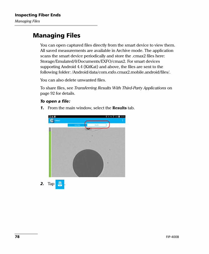
Managing FilesYou can open captured files directly from the smart device to view them. All saved measurements are available in Archive mode. The application scans the smart device periodically and store the .cmax2 files here: Storage/Emulated/0/Documents/EXFO/cmax2. For smart devices supporting Android 4.4 (KitKat) and above, the files are sent to the following folder: /Android/data/com.exfo.cmax2.mobile.android/files/.
You can also delete unwanted files.
To share files, see Transferring Results With Third-Party Applications on page 92 for details.
To open a file:
1. From the main window, select the Results tab.
2. Tap .
78 FIP-400B

Inspecting Fiber EndsManaging Files
3. In the Archive window, select Measurements.
4. Tap the selected file to open it.
Fiber Inspection Probe 79

Inspecting Fiber EndsManaging Files
To delete a file:
1. From the main window, select the Results tab.
2. Tap .
3. In the Archive window, tap Measurements or Reports.
80 FIP-400B

Inspecting Fiber EndsManaging Files
4. To enter the edition mode, press and hold any file in the Archive window.
5. Select the file you want to delete.
6. Tap .
7. When the application prompts you, tap OK or Cancel.
8. Tap to exit the edition mode.
9. Tap to exit the Archive window.
IMPORTANTIf you select files for deletion and you change your mind, ensure to unselect the files you want to keep.
Tap to select or unselect all files
Indicates you are working in edition mode.
Fiber Inspection Probe 81

Inspecting Fiber EndsAnalyzing Captures
Analyzing CapturesWith the capture analysis option, you can perform automated pass/fail analyses according to the criteria you have set.
Depending on the fiber probe that you have, you may have access to the following features:
Auto centering: displays the fiber in the middle of the image. It is compatible with all connector types and fibers with a cladding of 125 μm. The auto centering is enabled only in high magnification. Working with the auto centering feature can be useful with standard connectors. The auto centering is automatically activated when the auto focus is enabled.
Note: The auto centering feature is not available for FIP-425B and FIP-435B MF-Ready probes when testing multifiber connectors.
Auto focus: focuses on the connector image. It is enabled only in high magnification. The auto focus is only possible in Live Video mode, and if the focus is not done manually. It starts automatically when you insert an optical fiber connector. For more information, see Fiber Inspection Probe Tip Compatibility Chart on page 119.
Note: The auto focus feature is not available for FIP-425B MF-Ready probes when testing multifiber connectors.
82 FIP-400B

Inspecting Fiber EndsAnalyzing Captures
Auto capture: is possible with an acceptable focus level. It is enabled if the auto centering and auto focus are activated. The auto capture is possible only in high magnification. For more information, see Setting up Auto Capture on page 42.
Note: The auto capture feature is not available for FIP-425B and FIP-435B MF-Ready probes when testing multifiber connectors.
Auto analysis: displays 4 inspection zones: core, cladding, adhesive, and contact. It is enabled only in high magnification and with a good focus.
The results are available as an image or in a detailed table.
The Image shows the snapshot of what has been captured. You can see all the anomalies that have been detected.
Fiber Inspection Probe 83

Inspecting Fiber EndsAnalyzing Captures
The overlay shows the status of the analysis, the status per zone, the analysis zones, any anomaly (defects, scratches) found on the fiber endface. The color of the circles shows the status of the analysis zone:
Green: pass
Blue: no analysis was performed or the function is disabled
Red: fail
By default, the overlay is shown after an analysis, but you can hide it by tapping the image on screen.
The Results show detailed information for scratches and defects detected in each test zone and the corresponding test status.
84 FIP-400B

Inspecting Fiber EndsAnalyzing Captures
To view the results (single fiber or transceiver):
1. In Live Video mode, tap .
2. In the Results window, tap at the end of the Inspection Results row.
3. From the Inspection Results window, tap to return to the Results window.
Fiber Inspection Probe 85

Inspecting Fiber EndsAnalyzing Captures
To view the results (multifiber connector):
1. Perform the three captures. See Inspecting Multiple Fiber Ends (MF-Ready Probes Only) on page 65 for details.
2. In the Results window, tap the number of the fiber you want to view.
OR
Swipe directly on the screen to make your selection.
The color in thebackground indicates the
global status of theconnector.
Single-row multifiberconnector
Dual-row multifiber connector
86 FIP-400B

Inspecting Fiber EndsAnalyzing Captures
3. Tap at the end of the Inspection Results row.
4. From the Inspection Results window, you can select another fiber you want to view by tapping on its number.
5. Tap to return to the Results window.
Dual-row multifiber connector
Single-rowmultifiberconnector
Fiber Inspection Probe 87

Inspecting Fiber EndsCreating and Viewing Reports
Creating and Viewing ReportsYou can create a report based on the current inspection and analysis results. This report can be saved in PDF.
You can view the report as soon as it is generated, or you can select it in the Archive mode, or you can retrieve it here:Storage/Emulated/0/Documents/EXFO/cmax2. For smart devices supporting Android 4.4 (KitKat) and above, the files are sent to the following folder: /Android/data/com.exfo.cmax2.mobile.android/files/.
Note: The report creation is available only in the Results tab.
To create a report manually:
1. In Live Video mode, tap .
OR
If you are using an MF-Ready probe and you are inspecting a multifiber connector, perform the three captures. See Inspecting Multiple Fiber Ends (MF-Ready Probes Only) on page 65 for details.
88 FIP-400B

Inspecting Fiber EndsCreating and Viewing Reports
2. If you want to generate a report, in the Results window, tap .
Note: To create a report manually, the Generate report on save feature in the Application Settings must be disabled.
To activate automated report creation:
1. From the main window, tap .
Note: Depending on the smart device you are using, the application settings can be found in the menu button instead.
2. Select Application Settings.
Fiber Inspection Probe 89

Inspecting Fiber EndsCreating and Viewing Reports
3. Activate the On button next to the Generate report on save option.
4. Tap to return to the main window.
90 FIP-400B

Inspecting Fiber EndsCreating and Viewing Reports
To view an existing report:
1. If you do not want to view the report as soon as it is generated, in Live Video mode, tap the Results tab.
2. Tap .
3. In Archive mode, tap Reports.
4. Tap the selected file to open it.
5. Tap to return to the Results tab.
Fiber Inspection Probe 91

Inspecting Fiber EndsTransferring Results With Third-Party Applications
Transferring Results With Third-Party Applications
Third-party applications, such as Google Drive and Dropbox, are useful when you want to share measurement files with other users. The data that can be shared are measurement files (.cmax2) and images (.png).
By default, you will be prompted to select the application with which you want to work.
It is possible to share the FIP measurements as soon as the result of the analysis is displayed on screen and in Archive mode only. The Live Video mode does not allow it.
You need to disconnect the probe first if you want to share data with the smart device. Otherwise, the application buffers the FIP measurements.
When an image (.png) is send by e-mail, the e-mail is already pre-formatted with a summary of the information concerning the capture made. Information such as the file name and the inspection result is displayed.
Measurement files (.cmax2) and images (.png) can also be sent via SMS.
IMPORTANTIf you want to transfer results with a third-party application, ensure you first follow the steps related to the sharing process of the application you want to use, such as creating an account.
92 FIP-400B

Inspecting Fiber EndsTransferring Results With Third-Party Applications
To transfer the current result:
1. Ensure the Wi-Fi is activated on your smart device.
2. Ensure you are connected to a Wi-Fi network.
3. In Live Video mode, tap .
OR
If you are using an MF-Ready probe and you are inspecting a multifiber connector, perform the three captures. See Inspecting Multiple Fiber Ends (MF-Ready Probes Only) on page 65 for details.
Fiber Inspection Probe 93

Inspecting Fiber EndsTransferring Results With Third-Party Applications
4. In the Results tab, tap .
Note: To transfer a file, the Auto save feature in the Application Settings must be set to Always.
5. Select the type of file (.cmax2 or .png) you want to share.
6. Select the third-party application you want to work with.
7. Follow the instructions on-screen.
94 FIP-400B

Inspecting Fiber EndsTransferring Results With Third-Party Applications
To transfer one or more results from the Archive mode:
1. Ensure the Wi-Fi is activated on your smart device.
2. Ensure you are connected to a Wi-Fi network.
3. Tap the Results tab.
4. Tap .
5. In the Archive window, tap Measurements or Reports.
6. Select the measurement files you want to share by pressing and holding your finger on the screen.
Fiber Inspection Probe 95

Inspecting Fiber EndsTransferring Results With Third-Party Applications
7. Tap .
8. Select the type of file (.cmax2 or .png) you want to share.
Note: If you share a report, the type of file (PDF) is selected by default.
9. Select the third-party application you want to work with (Google Drive or Dropbox for example).
10. Follow the instructions on-screen.
Tap to select or unselect all files
Indicates you are working in edition mode.
96 FIP-400B

Inspecting Fiber EndsUpdating the Firmware
Updating the FirmwareThe FIP-400B is designed to provide firmware updates whenever necessary. This allows you to benefit from the updates of your unit each time you use it. The firmware updates can be recommended or required.
To notify you, a message box appears each time a firmware update is recommended or required.
In the case of a recommended firmware update, you can perform the update directly via Wi-Fi with your smart device.
For required firmware updates, you need to contact the technical support team.
Once an update is started, follow the indications to complete the process.
To perform a recommended or required firmware update:
When the application prompts you, follow the instructions on-screen.
Note: The application returns in Live Video mode as soon as the update is performed.
CAUTIONDo not disconnect the probe or turn off the unit when an update is in progress.
Fiber Inspection Probe 97


5 MaintenanceGeneral Maintenance
To help ensure long, trouble-free operation:
Always inspect fiber-optic connectors before using them and clean them if necessary.
Keep the unit free of dust.
Clean the unit casing with a cloth slightly dampened with water.
Store unit at room temperature in a clean and dry area. Keep the unit out of direct sunlight.
Avoid high humidity or significant temperature fluctuations.
Avoid unnecessary shocks and vibrations.
If any liquids are spilled on or into the unit, turn off the power immediately, disconnect from any external power source, remove the batteries and let the unit dry completely.
WARNINGThe use of controls, adjustments and procedures, namely for operation and maintenance, other than those specified herein may result in hazardous radiation exposure or impair the protection provided by this unit.
Fiber Inspection Probe 99

MaintenanceCleaning Lenses
Cleaning LensesLenses are part of the Fiber Inspection Probe. To help you with the cleaning process:
With a filtered air blower or a soft bristled brush, remove as much dust and dirt as possible.
Apply a few drops of cleaning solution, which is used to clean camera lenses, on a lens tissue, a cleaning cloth or a cotton swab. The lens cleaning solution especially manufactured by camera lens manufacturers can be used safely. Reagent grade isopropyl alcohol as well as deionized water can also be used safely.
Gently remove oil, fingerprints and grime from the lens surface, using a circular motion from the center outwards.
Recycling and DisposalFor complete recycling/disposal information, visit the EXFO Web site at www.exfo.com/recycle.
100 FIP-400B

MaintenanceRecharging the Battery (FIP-425B and FIP-435 Models Only)
Recharging the Battery (FIP-425B and FIP-435 Models Only)
The battery in your Fiber Inspection Probe is a Li-ion polymer battery with three-cell format. The charge status is shown with the LEDs on the Fiber Inspection Probe (see LED Indicators on page 6 for details). The application also indicates the charge status.
The micro USB adapter connector recharges the battery of the probe when it is low. You can recharge the battery with the provided USB cable and the adapter/charger that you connect to a power outlet. You can also use the provided USB cable alone that you connect to a USB port of a computer.
When the probe is connected to a power outlet or to a USB port, it still works via Wi-Fi.
It is possible to recharge the battery of the probe when it is connected to the USB port of a computer (500 mA).
CAUTIONOnly charge the battery with the USB cable and adapter/charger provided by EXFO with your unit.
You can purchase a new battery from EXFO.
IMPORTANT The battery is not charged at the factory. You must fully charge
it before using the unit for the first time. The battery is fully charged after a few hours or when the battery LED indicator stops flashing. The charge cycle starts and stops automatically.
The time required to charge the battery depends on various factors such as the ambient temperature.
To ensure that the battery functions or charges properly, keep it within operation and storage temperature range.
Fiber Inspection Probe 101

MaintenanceReplacing the Battery (FIP-425B and FIP-435 Models Only)
Replacing the Battery (FIP-425B and FIP-435 Models Only)
Your probe is powered by a Li-ion polymer rechargeable battery.
WARNING Your unit uses a three-cell battery that has been especially
designed for EXFO. For this reason, you can only replace it with a battery of the same type and model. The use of other batteries may damage your unit and compromise your safety.
Battery replacement should only be done by a qualified technician with the appropriate tools on an electronic bench or similar environment.
Do not throw the battery into fire or water and do not short-circuit the battery electrical contacts. Do not disassemble.
CAUTIONTo avoid irremediable damage to the battery, always remove the battery compartment door carefully, ensuring that the battery does not fall.
102 FIP-400B

MaintenanceReplacing the Battery (FIP-425B and FIP-435 Models Only)
To replace the battery:
1. Turn off the probe.
2. Unplug any power cable.
3. Using a screwdriver, remove the two screws that are located on the side of the probe.
4. Remove the battery compartment door.
CAUTIONGently pull on the battery to avoid damaging the wires.
Screws
Battery compartment door
Fiber Inspection Probe 103

MaintenanceReplacing the Battery (FIP-425B and FIP-435 Models Only)
5. Remove the battery.
6. Replace the battery, respecting the polarity (black, yellow, and red wires).
7. Close the battery compartment door.
8. Using a screwdriver, put the screws that you have removed at step 3 back in place.
Battery
Wires
104 FIP-400B

6 TroubleshootingSolving Common Problems
The table below presents common problems and their solutions.
Problem Solution
I cannot analyze an image
The image is not focused properly; use the focus knob on the probe until the focus indicator displays the best value available. Yellow indicates an acceptable range, and green shows the preferred range.
Ensure that the connector is aligned properly. When testing a multifiber connector with an MF-Ready probe, ensure the key of the nozzle is properly aligned with the notch of the inspection tip (see Changing the FIP Nozzle (MF-Ready Probes Only) on page 25 for details).
Ensure that the focus value is sufficient to perform the analysis.
Ensure that you are using a high magnitude level.
I cannot see the fiber on-screen
Verify the probe connection status to see if ConnectorMax2 Mobile is detecting the probe properly. If the probe is connected properly, close ConnectorMax2 Mobile and open it again.
Ensure that the Wi-Fi is on.
Ensure that the probe is on.
The FIP internal temperature is too high
Let the FIP cool down.
The auto centering does not function properly
Clean the connector.
Adjust the image focus.
A connection error occurred
Ensure that the probe is not currently in use by another application.
Try to connect the probe again.
Fiber Inspection Probe 105

TroubleshootingSolving Common Problems
An APC fiber is connected to an FIP-435B probe, the blue LED is blinking and the motor is not running
Try to put the fiber back in place.
Refresh rate is very low Ensure that the power saving mode is deactivated.
On your smart device, close the applications that are not in use.
Reduce the number of probes operating in the vicinity.
Bring the probe and the smart device closer together.
The FIP status LED blinks red for 2 seconds in Live Video mode and turns from unlit to blue (auto focus timeout)
Try to put the fiber back in place.
The FIP status LED blinks red for 2 seconds when a capture is performed and no analysis results are available
There was an analysis error. Repeat the inspection process.
The user interface displayed in the application is truncated.
Change font size in the smart device settings to facilitate reading comprehension.
The list of available FIPs is empty.
Ensure that the Wi-Fi is on.
Ensure that the probe is on.
A probe is no longer listed among the list of available FIPs for connection.
Wait a few minutes for the probe to appear in the list of available FIPs.
Connect the Wi-Fi probe with a USB cable.
Problem Solution
106 FIP-400B

TroubleshootingSolving Common Problems
The FIP measurement is corrupted when it is imported from a computer to the smart device via a USB cable.
The corruption seems to be caused by the smart device drivers. This is not caused by the ConnectorMax2 Mobile application.
Try to transfer the files to the smart device using a cloud application such as Google Drive.
The ConnectorMax2 Mobile application icon is not available in the list of the applications displayed.
Ensure that the smart device is not in Safe Mode. If so, restart the smart device.
Ensure that the ConnectorMax2 Mobile application was installed from the current user account (not from another account).
You see a message indicating that there is a problem with the connection.
If the probe is already in use by another device, disconnect the probe from the device and try to connect it again.
If the probe is connected via USB to a computer or EXFO platform and the ConnectorMax2 application is in use, disconnect the probe from the USB port and close ConnectorMax2 on the computer, then try to connect the probe again.
If the device cannot connect via Wi-Fi to the probe and connects to the previous Wi-Fi connection, use the device settings to connect to the probe instead of connecting the probe via the ConnectorMax2 Mobile application. To return to the previous connection, use the device settings as well.
The image displayed in Live Video mode is blinking.
Ensure that the type of connector selected matches the type of connector connected to the probe.
Problem Solution
Fiber Inspection Probe 107

TroubleshootingChanging the File Contents
Changing the File ContentsThe application allows you to choose between two different file formats. Each format is used for different purposes.
enhanced format: used to solve troubleshooting problems. This type of format should be selected when it is recommended by the technical support. It increases significantly the file size.
normal format: selected by default.
A message box indicates that you need to perform a required firmware update.
Contact EXFO for technical support.
The wireless probe is properly connected in the Wi-Fi settings but it is impossible to connect to the probe in the ConnectorMax2 Mobile application with an Android smart device.
Ensure your Android smart device is not configured to connect automatically to a mobile data network. (You can consult the documentation that came with your Android smart device to configure the settings properly.)
Contact EXFO for technical support if the problem still persists.
Problem Solution
108 FIP-400B

TroubleshootingChanging the File Contents
To change the file contents:
1. From the main window, tap .
Note: Depending on the smart device you are using, the application settings can be found in the menu button instead.
2. Select Application Settings.
Fiber Inspection Probe 109

TroubleshootingChanging the File Contents
3. Under Multifiber, tap Preferred file contents.
4. Select Normal (Recommended) or Enhanced.
5. Tap OK to confirm your choice.
6. Tap to return to the main window.
110 FIP-400B

TroubleshootingContacting the Technical Support Group
Contacting the Technical Support GroupTo obtain after-sales service or technical support for this product, contact EXFO at one of the following numbers. The Technical Support Group is available to take your calls from Monday to Friday, 8:00 a.m. to 7:00 p.m. (Eastern Time in North America).
For detailed information about technical support, and for a list of other worldwide locations, visit the EXFO Web site at www.exfo.com.
If you have comments or suggestions about this user documentation, you can send them to [email protected].
To accelerate the process, please have information such as the name and the serial number (see the product identification label), as well as a description of your problem, close at hand.
Technical Support Group400 Godin AvenueQuebec (Quebec) G1M 2K2CANADA
1 866 683-0155 (USA and Canada)Tel.: 1 418 683-5498Fax: 1 418 [email protected]
Fiber Inspection Probe 111

TroubleshootingViewing Information About ConnectorMax2 Mobile
Viewing Information About ConnectorMax2 Mobile
You can view information about ConnectorMax2 Mobile such as the version number and different policies on your smart device.
To view ConnectorMax2 Mobile information:
1. From the main window, tap .
Note: Depending on the smart device you are using, the about button can be found in the menu button instead.
2. Select About.
3. Under Version Information and General Information, select the information you want to view.
4. Tap to return to the main window.
112 FIP-400B

TroubleshootingViewing Online Help
Viewing Online HelpYou can view the online help for ConnectorMax2 Mobile at any time.
To view the online help:
1. From the main window, tap .
Note: Depending on the smart device you are using, the about button can be found in the menu button instead.
2. Select Help.
3. Under Guides, select the document you want to view.
4. Tap to return to the main window.
Fiber Inspection Probe 113

TroubleshootingTransportation
TransportationMaintain a temperature range within specifications when transporting the unit. Transportation damage can occur from improper handling. The following steps are recommended to minimize the possibility of damage:
Pack the unit in its original packing material when shipping.
Avoid high humidity or large temperature fluctuations.
Keep the unit out of direct sunlight.
Avoid unnecessary shocks and vibrations.
114 FIP-400B

7 WarrantyGeneral Information
EXFO Inc. (EXFO) warrants this equipment against defects in material and workmanship for a period of one year from the date of original shipment. EXFO also warrants that this equipment will meet applicable specifications under normal use.
During the warranty period, EXFO will, at its discretion, repair, replace, or issue credit for any defective product, as well as verify and adjust the product free of charge should the equipment need to be repaired or if the original calibration is erroneous. If the equipment is sent back for verification of calibration during the warranty period and found to meet all published specifications, EXFO will charge standard calibration fees.
THIS WARRANTY IS IN LIEU OF ALL OTHER WARRANTIES EXPRESSED, IMPLIED, OR STATUTORY, INCLUDING, BUT NOT LIMITED TO, THE IMPLIED WARRANTIES OF MERCHANTABILITY AND FITNESS FOR A PARTICULAR PURPOSE. IN NO EVENT SHALL EXFO BE LIABLE FOR SPECIAL, INCIDENTAL, OR CONSEQUENTIAL DAMAGES.
IMPORTANTThe warranty can become null and void if:
unit has been tampered with, repaired, or worked upon by unauthorized individuals or non-EXFO personnel.
warranty sticker has been removed.
case screws, other than those specified in this guide, have been removed.
case has been opened, other than as explained in this guide.
unit serial number has been altered, erased, or removed.
unit has been misused, neglected, or damaged by accident.
Fiber Inspection Probe 115

WarrantyLiability
LiabilityEXFO shall not be liable for damages resulting from the use of the product, nor shall be responsible for any failure in the performance of other items to which the product is connected or the operation of any system of which the product may be a part.
EXFO shall not be liable for damages resulting from improper usage or unauthorized modification of the product, its accompanying accessories and software.
ExclusionsEXFO reserves the right to make changes in the design or construction of any of its products at any time without incurring obligation to make any changes whatsoever on units purchased. Accessories, including but not limited to fuses, pilot lamps, batteries and universal interfaces (EUI) used with EXFO products are not covered by this warranty.
This warranty excludes failure resulting from: improper use or installation, normal wear and tear, accident, abuse, neglect, fire, water, lightning or other acts of nature, causes external to the product or other factors beyond the control of EXFO.
CertificationEXFO certifies that this equipment met its published specifications at the time of shipment from the factory.
IMPORTANTIn the case of products equipped with optical connectors, EXFO will charge a fee for replacing connectors that were damaged due to misuse or bad cleaning.
116 FIP-400B

WarrantyService and Repairs
Service and RepairsEXFO commits to providing product service and repair for five years following the date of purchase.
To send any equipment for service or repair:
1. Call one of EXFO’s authorized service centers (see EXFO Service Centers Worldwide on page 118). Support personnel will determine if the equipment requires service, repair, or calibration.
2. If equipment must be returned to EXFO or an authorized service center, support personnel will issue a Return Merchandise Authorization (RMA) number and provide an address for return.
3. If possible, back up your data before sending the unit for repair.
4. Pack the equipment in its original shipping material. Be sure to include a statement or report fully detailing the defect and the conditions under which it was observed.
5. Return the equipment, prepaid, to the address given to you by support personnel. Be sure to write the RMA number on the shipping slip. EXFO will refuse and return any package that does not bear an RMA number.
Note: A test setup fee will apply to any returned unit that, after test, is found to meet the applicable specifications.
After repair, the equipment will be returned with a repair report. If the equipment is not under warranty, you will be invoiced for the cost appearing on this report. EXFO will pay return-to-customer shipping costs for equipment under warranty. Shipping insurance is at your expense.
Routine recalibration is not included in any of the warranty plans. Since calibrations/verifications are not covered by the basic or extended warranties, you may elect to purchase FlexCare Calibration/Verification Packages for a definite period of time. Contact an authorized service center (see EXFO Service Centers Worldwide on page 118).
Fiber Inspection Probe 117

WarrantyEXFO Service Centers Worldwide
EXFO Service Centers WorldwideIf your product requires servicing, contact your nearest authorized service center.
To view EXFO's network of partner-operated Certified Service Centers nearest you, please consult EXFO's corporate website for the complete list of service partners: http://www.exfo.com/support/services/instrument-services/exfo-service-centers.
EXFO Headquarters Service Center400 Godin AvenueQuebec (Quebec) G1M 2K2CANADA
1 866 683-0155 (USA and Canada)Tel.: 1 418 683-5498Fax: 1 418 [email protected]
EXFO Europe Service CenterWinchester House, School LaneChandlers Ford, Hampshire S053 4DGENGLAND
Tel.: +44 2380 246800Fax: +44 2380 [email protected]
EXFO Telecom Equipment(Shenzhen) Ltd.3rd Floor, Building C,FuNing Hi-Tech Industrial Park, No. 71-3, Xintian Avenue, Fuyong, Bao’An District, Shenzhen, China, 518103
Tel: +86 (755) 2955 3100Fax: +86 (755) 2955 [email protected]
118 FIP-400B

A Fiber Inspection Probe Tip Compatibility Chart
With some tips that include lenses, and before performing an automatic focus, you must adjust the focus manually for the first inspection.
Note: The tips for which the probe requires a manual focus before the first inspection are listed in the table below.
To reach the focus level manually:
1. Bring the focus manually close to the focal point.
2. Activate the auto focus or press the magnification control button on the probe and hold it down until the auto focus is activated again.
The table below establishes the Fiber Inspection Probe tip compatibility with the different operations: fiber inspection, auto analysis (option), auto focus (option), and auto detection (option) provided with the ConnectorMax2 Mobile application.
Note: You can install the tips described below on FIP-425B and FIP-435B MF-Ready probes. For more information on the features available for your probe, see Available Models on page 5.
Tip Description Tip Code Inspection(all models)
Analysis(FIP-425B/FIP-435B)
Auto focus(FIP-435B)
ConnectorAuto
detection(FIP-435B)
Uni.2.5mm for PC connector
FIPT-400-U25M OK OK OK OK
Uni.2.5mm for APC connector
FIPT-400-U25MA OK OK OK OK
Uni.1.25mm for PC Connector
FIPT-400-U12M OK OK OK OK
Uni.1.25mm for APC connector
FIPT-400-U12MA OK OK OK OK
Fiber Inspection Probe 119

Fiber Inspection Probe Tip Compatibility Chart
FC APC tip for bulkhead adapter
FIPT-400-FC-APC OK OK OK OK
FC and SC tip for bulkhead adapter
FIPT-400-FC-SC OK OK OK OK
ST for UPC bulkhead adapter
FIPT-400-ST OK OK OK OK
E-2000 for PC bulkhead
FIPT-400-E2000 OK OK OK OKa
E-2000 for APC bulkhead adapter
FIPT-400-E2000-APC
OK OKa OK OKa
FIPT-400-FC-SC-A6 bulkhead adapter
FIPT-400-FC-SC-A6
OK OK OK NO
MU for UPC bulkhead adapter
FIPT-400-MU OK OK OK OK
MU-L for UPC bulkhead adapter
FIPT-400-MU-L OK OK OK OK
149 mm, Extended MU tip for PC bulkhead adapter
FIPT-400-MU-L-149
OK OK OKb NO
ODC 4 Pin Plug (female) Guide tip
FIPT-400-ODC-4PIN-P
OK OK OK OK
ODC Socket (male) tip
FIPT-400-ODC-S OK OK OK OK
ODC Universal Guide tip
FIPT-400-ODC-U OK OK OK OK
ODC 2 Pin Plug (female) Guide tip
FIPT-400-ODC-2PIN-P
OK OK OK OK
Tip Description Tip Code Inspection(all models)
Analysis(FIP-425B/FIP-435B)
Auto focus(FIP-435B)
ConnectorAuto
detection(FIP-435B)
120 FIP-400B

Fiber Inspection Probe Tip Compatibility Chart
D4 bulkhead adapter
FIPT-400-D4 OK OK OK OK
FIPT-400-U20M2 is for male ferule connector
FIPT-400-U20M2 OK OK OK OK
FIPT-400-Lemo for bulkhead adapter
FIPT-400-Lemo OK OK OK OK
OptiTap for APC bulkhead adapter
FIPT-400-OTAP-APC
OK NO NO NO
LC for PC bulkhead FIPT-400-LC OK OK OK OK
LC for APC bulkhead adapter
FIPT-400-LC-APC OK OK OK OK
LC for bulkhead adapter 60 Degree Angled
FIPT-400-LC-A6 OK OK OK NO
Extended LC tip for PC bulkhead adapter
FIPT-400-LC-L OK OK OKb OKa
137 mm, Extended LC tip for PC bulkhead adapter
FIPT-400-LC-L-137
OK OK OKb NO
LX5 for UPC bulkhead adapter
FIPT-400-LX.5 OK OK OK OK
LX5 for APC bulkhead adapter
FIPT-400-LX5-APC
OK NO OK OK
Bulkhead adapter Westover
FIPT-400-ADAPTER
OK N/A N/A N/A
Tip Description Tip Code Inspection(all models)
Analysis(FIP-425B/FIP-435B)
Auto focus(FIP-435B)
ConnectorAuto
detection(FIP-435B)
Fiber Inspection Probe 121

Fiber Inspection Probe Tip Compatibility Chart
Contact your vendor for additional information regarding the most recent Fiber Inspection Probe tips that are not listed above.
SMA bulkhead adapter
FIPT-400-SMA OK NO OKc OKc
SMA male connector
FIPT-400-SMAM OK NO OKc OKc
Uni. 1.6 for PC connector
FIPT-400-U16M OK NO OK OK
MTRJ bulkhead adapter
FIPT-400-MTRJ OK NO NO NO
SC APC for bulkhead
FIPT-400-SC-APC OK OK OK OK
Extended SC tip for PC bulkhead adapter
FIPT-400-SC-L OK OK OKb OKa
149 mm Extended SC tip for PC bulkhead adapter
FIPT-400-SC-L-149
OK OK OKb NO
SC for APC bulkhead adapter – extended
FIPT-400-SC-APC-L
OK OKa OK OKa
a. Use version B of the tip or higher.b. A manual focus is required for the first inspection.c. Only with a 125 μm ferrule.
Tip Description Tip Code Inspection(all models)
Analysis(FIP-425B/FIP-435B)
Auto focus(FIP-435B)
ConnectorAuto
detection(FIP-435B)
122 FIP-400B

Index
Index
#................................................................. 36
3G, 4G LTE communications ....................... 22
Aactivating features
auto analysis.................................... 64, 71auto capture.......................................... 64auto centering ....................................... 64auto focus ....................................... 64, 71automated report creation .................... 89
activeidentifier ................................................ 40increment .............................................. 38
adapter/charger..................................... 4, 101adhesive, inspection zone ........................... 83adjusting brightness.................................... 31after-sales service ...................................... 111analysis
of captures ............................................ 82status..................................................... 84stopped on first fail ............................... 55zones ..................................................... 84
autoanalysis ...................................... 64, 71, 83capture ...................................... 42, 64, 83centering ......................................... 64, 82focus.......................................... 64, 71, 82save ....................................................... 77
automated report creation.......................... 89autonaming
configuration......................................... 39feature................................................... 39preview.................................................. 39tab......................................................... 40
Fiber Inspection Probe
availablefeatures.................................................... 5models ..................................................... 5
Bbattery
compartment door .................. 2, 3, 4, 103LED indicator.................... 2, 3, 4, 6, 8, 101recharging ....................................... 4, 101replacement................................. 102, 103status ................................................. 9, 10
blinking image........................................... 107brightness.................................................... 31button
capture, on probe .................................... 3capture, on screen ............................. 9, 10description............................................... 9disconnecting the probe .................... 9, 10magnification control .............................. 3
Ccapture
analyzing ............................................... 82button, on probe ................................. 2, 3button, on screen .............................. 9, 10
capture in multifiber inspectionnumber one ........................................... 72number three......................................... 74number two........................................... 73
cautionof personal hazard ................................. 11of product hazard .................................. 11
certification information................................ vchanging
default name ......................................... 35file contents ......................................... 108file format.............................................. 53
123

Index
nozzle .............................................. 25, 28tips ........................................................ 24
charge status......................................... 4, 101choosing
connector .............................................. 61connector subtype................................. 68connector tip ......................................... 63multiple fiber connector ........................ 67test configuration.................................. 44
cladding, inspection zone ........................... 83cleaning lenses .......................................... 100configuration of fibers ................................ 69configuring
file name ............................................... 39identification ......................................... 33incrementation ...................................... 37test ........................................................ 44
connecting the probe............................ 20, 21connection, lost .......................................... 20connector
global status.......................................... 86key orientation ...................................... 69subtype.................................................. 68tip, type ................................................. 63type ....................................................... 61
ConnectorMax2 Mobileapplication............................................. 19installation............................................. 20introduction ............................................ 9
contact, inspection zone ............................. 83conventions, safety ..................................... 11core, inspection zone .................................. 83creating report
automatic method................................. 89manual method..................................... 88
current result, transferring .......................... 93custom configurations
deleting ................................................. 46importing .............................................. 48
customer service........................................ 117
Ddark fiber..................................................... 70data sharing .................................... 92, 93, 95decrementing file name......................... 35, 75default settings ........................................... 57defects found on fiber endface ................... 84deleting
files .................................................. 78, 80test configurations................................. 46
digital watermark .................................. 59, 65disconnecting the probe.............. 9, 10, 20, 23documentation, user ................................. 113
Eelectrical safety information ........................ 16enabling auto capture ................................. 42equipment ratings ....................................... 17equipment returns..................................... 117existing report, viewing ............................... 91external Wi-Fi network ................................ 19eye icon ................................................. 50, 52
Ffactory settings............................................ 57fail status detected on fiber......................... 55feature
auto capture .......................................... 42auto save ............................................... 76file contents ......................................... 108generate report on save......................... 89
fibersconfiguration in connector .................... 69dark ....................................................... 70endface.................................................. 84identifying by name............................... 35
file nameconfiguration ......................................... 39preview.................................................. 39
124 FIP-400B

Index
filesdeleting ........................................... 78, 80managing .............................................. 78modifying contents.............................. 108modifying format .................................. 53name decrementing......................... 35, 75name incrementing ......................... 35, 75naming .................................................. 39opening ................................................. 78saving automatically ........................ 75, 77saving manually............................... 75, 76sharing current result ............................ 93sharing from Archive mode ................... 95
firmware update ................................. 97, 108first capture in multifiber inspection ........... 72focus
indicator ........................ 9, 10, 60, 66, 105knob ............................................ 2, 3, 105level ......................................... 42, 83, 119peak................................................. 60, 66value.................................................... 105
frequency, Wi-Fi ........................................... vii
Ggenerating report
automatically ......................................... 89manually................................................ 88
geolocation ................................................. 21global status of the connector .................... 86Google
account.................................................. 19Play Store......................................... 19, 20
GPS data ..................................................... 21green indicator, focus ................... 60, 66, 105
Hhelp........................................................... 113hiding
overlay................................................... 84test configurations ................................ 49
high magnification level .............................. 42
Iicon
battery status..................................... 9, 10eye ................................................... 50, 52user preferences................................. 9, 10
identificationfeature ................................................... 33tab ......................................................... 34
identification label..................................... 111identifiers
active ..................................................... 40inactive .................................................. 40removing ......................................... 38, 40
imageblinking................................................ 107presenting results .................................. 83
importing test configurations...................... 48increment
active ..................................................... 38feature ................................................... 35inactive .................................................. 38tab ......................................................... 38value ...................................................... 38
incrementing file name.......................... 35, 75information about ConnectorMax2
Mobile ......................................... 112inspecting fiber ends
multiple ........................................... 65, 67single fiber ....................................... 59, 61transceivers ...................................... 59, 61
inspection mode, Live Video...... 59, 61, 65, 67inspection tip
location on probe .................................... 3movable part ......................................... 27notch ................................. 26, 27, 28, 105removing ............................................... 30
inspection zoneadhesive................................................. 83cladding................................................. 83contact................................................... 83core........................................................ 83
Fiber Inspection Probe 125

Index
installingConnectorMax2 Mobile ......................... 20inspection tip on probe ......................... 26nozzle .................................................... 28
interchangeable adapter tips ................ 2, 4, 6internal temperature ................. 5, 59, 65, 105
Kkey
down ......................................... 26, 28, 69of the nozzle............................ 26, 28, 105of the probe .......................................... 27up.............................................. 26, 28, 69
keyboard ............................................... 34, 40
Llabel, identification ................................... 111LED
battery............................. 2, 3, 4, 6, 8, 101status................................... 2, 3, 6, 7, 106Wi-Fi ........................................ 2, 3, 4, 6, 8
lenses, cleaning ......................................... 100level of magnification.............................. 3, 42Li-ion polymer battery ....................... 101, 102Live Video, inspection mode...... 59, 61, 65, 67lost connection ........................................... 20
Mmagnification control button.................... 2, 3maintenance
general information............................... 99recharging the battery......................... 101replacing the battery ................... 102, 103
making a capture .................................... 9, 10managing
files........................................................ 78test configurations ................................ 44
manual focus level .................................... 119micro USB adapter connector........ 2, 3, 4, 101microphone........................................... 34, 40
mobile application....................................... 19models
available................................................... 5modifying
file contents ......................................... 108file format.............................................. 53
movable part of the inspection tip ........ 27, 30moving
identifiers............................................... 40increments ............................................. 38
multiple fiberconnector .............................................. 67inspection ........................................ 65, 67viewing results ....................................... 86
Nnaming files automatically............... 35, 39, 75notch of the inspection tip ...... 26, 27, 28, 105nozzle
changing................................................ 25installation............................................. 28key down ............................................... 69key for installation ......................... 26, 105key up.................................................... 69
number of digits displayed.......................... 36
Oonline help ................................................ 113opening files................................................ 78orientation of the key.................................. 69overlay......................................................... 84
Ppeak focul level...................................... 60, 66performing
firmware update .................................... 97first capture ........................................... 72second capture ...................................... 73third capture.......................................... 74
position displayed on inspection tip ............ 73
126 FIP-400B

Index
preferred file format.................................... 53preview of the file name ............................. 39probe
battery compartment door ...... 2, 3, 4, 103battery LED.............................. 2, 3, 4, 6, 8capture control button ........................ 2, 3connection....................................... 20, 21disconnection .................................. 20, 23focus knob................................... 2, 3, 105inspection tip................................. 3, 4, 25interchangeable adapter tips ............... 2, 4key......................................................... 27magnification control button .............. 2, 3micro USB adapter connector .. 2, 3, 4, 101nozzle ............................................ 3, 4, 25protective cap.......................................... 4retaining nut.................................. 2, 3, 24status LED.................................... 2, 3, 6, 7tips .......................................................... 6trigger ..................................... 3, 4, 27, 30warmup....................................... 5, 59, 65Wi-Fi LED ................................. 2, 3, 4, 6, 8
probe featuresauto analysis.......................................... 83auto capture.......................................... 83auto centering ....................................... 82auto focus ............................................. 82
productidentification label............................... 111specifications ......................................... 10
protective cap ............................................... 4
Rreaching the focus level manually ............. 119recharging the battery .......................... 4, 101recommended update................................. 97red indicator.......................................... 60, 66removable nozzle ................................ 3, 4, 25removing
configurations from the hidden list ....... 51identifier .......................................... 38, 40
inspection tip ......................................... 30nozzle .................................................... 28
replacing the battery ..................... 4, 102, 103report creation
automatic method ................................. 89manual method ..................................... 88
required update................................... 97, 108restoring to default settings ........................ 57results
presented as an image........................... 83presented in a table ............................... 84transferring...................................... 92, 95
retaining nut ....................................... 2, 3, 24return merchandise authorization (RMA) .. 117
Ssafety
caution................................................... 11conventions ........................................... 11warning ................................................. 11
saving filesautomatically ................................... 75, 77manually .......................................... 75, 76
scratches found on fiber endface ................ 84second capture in multifiber inspection....... 73selecting
fibers configuration ............................... 69file contents ......................................... 108file format.............................................. 53test configurations................................. 44
selecting featuresauto analysis .................................... 64, 71auto capture .......................................... 64auto centering ....................................... 64auto focus........................................ 64, 71
separator in the file name ..................... 39, 41service and repairs ..................................... 117service centers ........................................... 118setting up
auto capture .......................................... 42autonaming ........................................... 39
Fiber Inspection Probe 127

Index
identification ......................................... 33incrementation ...................................... 35
settingsbrightness.............................................. 31factory ................................................... 57
SF connector ............................................... 61sharing
current result ......................................... 93files from Archive mode......................... 95
shipping to EXFO ...................................... 117single fiber
inspection........................................ 59, 61viewing results....................................... 85
smart devicesmicrophone ..................................... 34, 40virtual keyboard............................... 34, 40
specifications, product ................................ 10standby mode ............................................. 20start value ................................................... 38status
LED ...................................... 2, 3, 6, 7, 106of the analysis........................................ 84per zone ................................................ 84
stop value ................................................... 38stopping analysis on first fail....................... 55storage requirements .................................. 99storing files ..................................... 75, 76, 77symbols, safety............................................ 11
Ttab
Autonaming .......................................... 40Identification ......................................... 34Increment .............................................. 38
technical specifications ............................... 10technical support ...................................... 111temperature for storage.............................. 99test configurations
deleting ................................................. 46hiding .................................................... 49importing .............................................. 48
managing .............................................. 44removing from the hidden list ............... 51selecting ................................................ 44
third capture in multifiber inspection .......... 74third-party applications ............................... 92tips
changing................................................ 24compatibility chart............................... 119types ........................................................ 6
transceiversconnector .............................................. 61inspection ........................................ 59, 61viewing results ....................................... 85
transferringcurrent result ......................................... 93results from Archive mode..................... 95
transportation requirements ............... 99, 114trigger ........................................... 3, 4, 27, 30types of separator ................................. 39, 41
Uupdating firmware .............................. 97, 108USB cable .............................................. 4, 101user preferences icon............................... 9, 10using ConnectorMax2 Mobile...................... 19
Vviewing
existing reports ...................................... 91fiber ends............................................... 59information about ConnectorMax2
Mobile .................................. 112multifiber connector results ................... 86multiple fiber ends................................. 65online help........................................... 113single fiber results.................................. 85transceivers results................................. 85
virtual keyboard..................................... 34, 40
128 FIP-400B

Index
Wwarmup period ................................. 5, 59, 65warranty
certification ......................................... 116exclusions ............................................ 116general ................................................ 115liability................................................. 116null and void........................................ 115
watermark............................................. 59, 65Wi-Fi
frequency band data .............................. viiLED .......................................... 2, 3, 4, 6, 8network ................................................. 19
wireless probeconnection....................................... 20, 21disconnection .................................. 20, 23
Yyellow indicator............................. 60, 66, 105
Fiber Inspection Probe 129


www.EXFO.com · [email protected]
P/N: 1071994
CORPORATE HEADQUARTERS 400 Godin Avenue Quebec (Quebec) G1M 2K2 CANADATel.: 1 418 683-0211 · Fax: 1 418 683-2170
EXFO AMERICA 3400 Waterview Parkway Suite 100 Richardson, TX 75080 USATel.: 1 972-761-9271 · Fax: 1 972-761-9067
EXFO EUROPE Winchester House,School Lane
Chandlers Ford, Hampshire S053 4DG ENGLANDTel.: +44 2380 246 800 · Fax: +44 2380 246 801
EXFO ASIA-PACIFIC 62 Ubi Road 1,#09-01/02 Oxley Bizhub 2
SINGAPORE 408734Tel.: +65 6333 8241 · Fax: +65 6333 8242
EXFO CHINA Beijing Global Trade Center, Tower C, Room 1207, 36 North Third Ring Road East, Dongcheng District
Beijing 100013 P. R. CHINATel.: +86 (10) 5825 7755 · Fax: +86 (10) 5825 7722
EXFO SERVICE ASSURANCE 250 Apollo Drive Chelmsford MA, 01824 USA Tel.: 1 978 367-5600 · Fax: 1 978 367-5700
EXFO FINLAND Elektroniikkatie 2 FI-90590 Oulu, FINLANDTel.: +358 (0) 403 010 300 · Fax: +358 (0) 8 564 5203
TOLL-FREE (USA and Canada) 1 800 663-3936
© 2017 EXFO Inc. All rights reserved.Printed in Canada (2017-07)