user guide doortel 4 - rocom gmbh · user guide doortel 4 issue 1.01 page 5 connection diagram...
TRANSCRIPT

User guide Doortel 4 Issue 1.01
Page 1
User guide
Doorstation with telephone lineinterface for the connection
to telephone systemsVersion with up to 4 bell buttons
DOORTEL 4 MDDOORTEL 4 AVDOORTEL 4 ESDOORTEL 4 BG

User guide Doortel 4 Issue 1.01
Page 2
ContentsDescription ................................................................................................................ 3Features ..................................................................................................................... 4Connection diagram .................................................................................................. 5View of the DOORTEL 4 electronic board. Connections. ............................................. 6View of the DOORTEL 4 electronic board. Jumpers. ................................................... 7Installation ................................................................................................................ 8How to program a dial number ............................................................................... 10How to delete a dial number ................................................................................... 10How to program the activation time forthe contact 1 and 2 ................................................................................................. 11How to program the auto disconnectafter door opening .................................................................................................. 11How to program the manual/automaticmode of the contact 2 ............................................................................................. 12How to program the pulsed or continuosactivation of the contact 2 ...................................................................................... 12How to use .............................................................................................................. 13Technical data .......................................................................................................... 14Programmation overview ........................................................................................ 15

User guide Doortel 4 Issue 1.01
Page 3
Description
The doorstation with telephone line interface DOORTEL 4 can be connected to standardanalogue T/R extension lines of any PABX. The unit is delivered in four different versions:the BG version for installation behind existing panels, the MD version with a designeraluminium case, the AV version with a vandal proofed aluminum panel and the ESversion with a stainless steel casing. All versions can have up to four bell chime button.The ES Version has only three button in his standard version.
The connection of the doorstation to the telephone switch is done using two wires.Further a 12 Vac power supply is needed for the door opener and the illumination lampin the doorstation. For this another two wires are necessary. We suggest in any case toprovide an illumination of the doorstation as the lamps heat will ensure that thecondensing water formation and a too low operating temperature can be prevented.Please take care that in some extrem enviroment situations the unit might need an addon heating element. The device is deliverd with microphone and loudspeaker. Thevolume of the loudspeaker and the microphone can be regulated.
The unit is activated using the bell buttons. Herefore a galvanic, powerless contact isneeded. Please take care that the activation LED will be lit only when the device is busy.After the closing of one of the buttons contact the device will size the line, the red LEDwill be lit, and the programmed telephone number is dialed using the selected mode:rotary dial or DTMF. The telephone numer is programmed using a DTMF dial procedure.The digits 0 to 9 and the special DTMF code * and # can be programmed as part of thetelephone number. Using the same DTMF dial procedure also all other programmationsare done. Only the setting for the dial mode, the hardware timer and the auto answerare done using jumpers on the board.
If needed the DOORTEL 4 doorstation with telephone line interface can also be called.As soon as the first call signal is recognized the unit will answer the call. After this anacknowledge tone is sent to the caller.
During the connection using a DTMF dial pad telephone a door opener contact can beactivated dialing the "7". With the digit "8" a second optional contact can be activated.The contacts are activated for a programmed time. And the end of this time theconnection is terminated automatically. This function can be deactivated using theprogramming functions.
The connection will be terminated as soon as a busy tone is surley detected. TheDOORTEL 4 can be released, without opening the door, dialing the DTMF digit "3"during the connection. If the called party doesn't answer the unit will drop theconnection after 7 ringback tones. For the enhanced security the unit has also ahardware timer. This will ensure that the connection is terminated in any case after thetime out. The time out can be set to 1, 2 or 4 minutes using jumper which can be findinside the unit.
The optional second contact, which is installed externally to the unit, can be
User guide Doortel 4 Issue 1.01
Page 4
programmed also for an automatic mode. Is this case the contact is activated as soonthe line is sized, for all the seizure time, or just for the duration of 2 seconds. Herewithvideocameras, or similar devices, can be activated together with the unit. For the secondcontact a relais unit 1471, 1471E or 1472 has to be installed. Furthermore the unit hasto be powered with a 12 Vac/dc supply.
Features
- Up to four bell buttons. Each button can be programmed with a 1 to 5 digit longnumber dial
- Programmation using DTMF tones- Programmable contact activation time- Settable auto answer function- High quality handsfree speach controlled unit- Tone detection- Volume regulation for loudspeaker and microphone- With DTMF dial controlled door opener contact- Optional external second relais (1471, 1471E or 1472) for the comand of videocameras
or a similar devices- Line disconnect with DTMF dial- Automatic line disconnect after door opening (programmable)- Connection to any PABX T/R analogue extension line- DTMF or rotary dial selectable- Programmable time out timer- External LED connectable

User guide Doortel 4 Issue 1.01
Page 5
Connection diagram
TransformerPRS 210
Door opener
PABX
Analogextens ion
line
- +
Sw2
Sw1
P2
P1
Sw6
1
2
4
1
2
4
Sw4
PT
Sw5
Sw3
ON
OFF
Door opener 1 12VacDOORTEL 4Screw connector
DOOR
Illumination
doorstation
TransformerPRS 210
230 Vac
- +
Sw2
Sw1
P2
P1
Sw6
1
2
4
1
2
4
Sw4
PT
Sw5
Sw3
ON
OFF
Door opener 2 12VacDOORTEL 4
Screw connector12V IN
DOORTEL 4Screw connector
+/-
Illuminationdoorstation
TransformatorPRS 210
Relais unit
1471, 1471E or 1472
230 Vac

User guide Doortel 4 Issue 1.01
Page 6
View of the DOORTEL 4 electronic board. Connections.
Analogue telephone line (T/R)
Connector external
LED
LED indicator
Connection external contact 2
Connection contact 1
Input 12 Vac/dc power supply (optional)
Volume
loudspeaker
Output 12Vdc
(12Vdc/GND)
Connection loudspeaker
(SPK/GND)
Connection microphone
(MIC(+)/8V(-))
Volume
microphone
- +
Sw
2
Sw1
P2
P1
Sw6
1
2
4
1
2
4
Sw
4
P T
Sw
5
Sw3
ON
OFF
User guide Doortel 4 Issue 1.01
Page 7
- +
Sw
2
Sw1
P2
P1
Sw6
1
2
4
1
2
4
Sw
4
P T
Sw
5
Sw3
ON
OFF
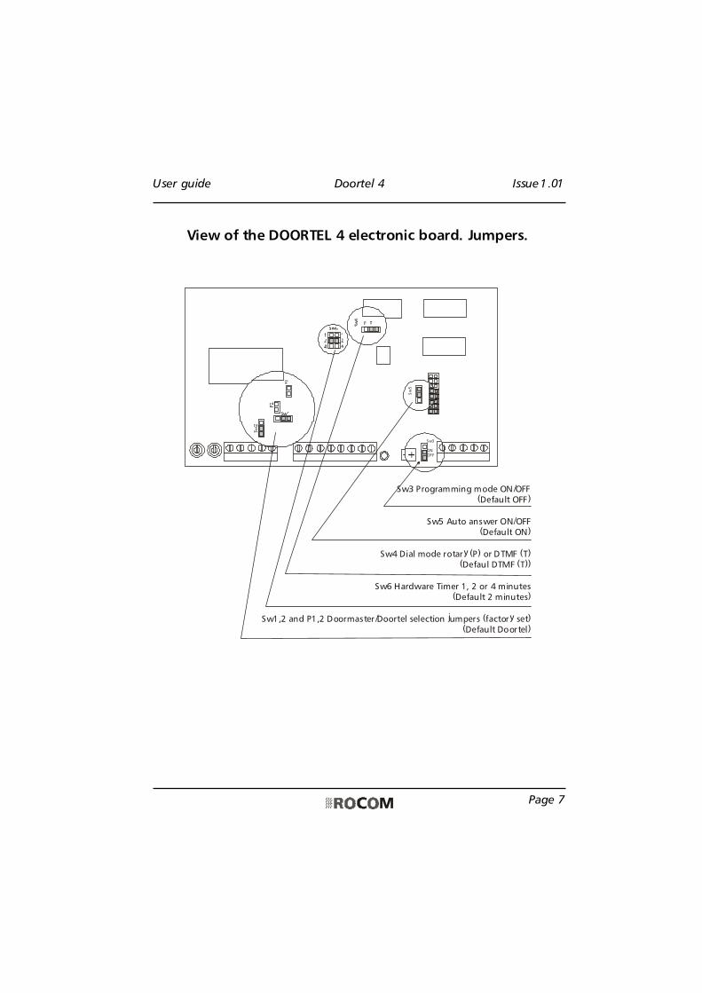
Sw3 Programming mode ON/OFF(Default OFF)
Sw5 Auto answer ON/OFF(Default ON)
Sw4 Dial mode rotary (P) or DTMF (T)(Defaul DTMF (T))
Sw6 Hardware Timer 1, 2 or 4 minutes(Default 2 minutes)
Sw1,2 and P1,2 Doormaster/Doortel selection jumpers (factory set)(Default Doortel)
View of the DOORTEL 4 electronic board. Jumpers.

User guide Doortel 4 Issue 1.01
Page 8
Depending on the delivered version install the DOORTEL 4 doorstation as required. Withflush mounting versions the front plate and the installed electronic board should be takeoff during the installation operations of the box. For the MD Version also for the wallmounting version the front plate and the installed electronic board should bedismounted for the installing operations. With the AV and ES version you can separatethe complete unit with front panel, back box and electronic board from the wallmounting case. In this case you don't need to dismount the electronic board. With theAV version with flush mounting installation do not forget to apply the delivered fittingstrip to the front panel.
With the BG version for installation behind existing panels, install the electronic board inhis case or letter box. Please take care that a too large distance between board andmicrophone can reduce the voice quality of the unit. The bell button contacts are tobe connected powerless. With the installation of the loadspeaker and the microphoneplease take care that enough acoustic separation between the two item is granted.Especially the backward generated sound waves from the loadspeaker should not getoutside the case or reach the microphone. If the delivered installation holders formicrophone and loadspeaker are used, this should not be a problem.
If possible use different cables to connect the telephone line and the AC power supplyfor the lamp and door opener. This will reduce the possibility to have "humming" noiseson the connection. After the installation and cabling using the in this documentationprovided connection diagram, the number to be dialled has to be programmed.Beforestarting with the programming procedure the program enable jumper SW3 has to be seton ON. Further also the dial mode jumper SW 4 has to be set on T (for tone dial) andthe jumper SW 5 for the auto answer has to be set on active. Both this last two settingare foreseen as default from the factory. Now call the unit using a telephone with anDTMF dial pad. Follow the programming procedure as described in the next pages. Thisitems can be programmed on the device:
- Program and delete the dial number for each bell button;- Activation time for the contact 1 and 2;- Automatic call termination after contact activation ON/OFF;- Manual or automatic function for the contact 2;- Pulsed (2 seconds) or continous activation of contact 2 with automatic function.
After the programmation of the telephone numbers you should select the appropiatedial mode for your PABX (jumper SW4, default is DTMF). Further also the auto answerfunction (jumper SW5, default ON) and the hardware timer (jumper SW6, default 2minutes) should be set as required. The unit is now ready to work. You should set up aconnection with the door unit. A regulation of the sending and receiving volume may benecessary. To do this you should use the regulators placed on the DOORTEL 4doorstation. Please take care to regulate VERY carefully. If this is done by two people itmight be helpful. If the loudspeaker will send only "broken" tones, or it has a too
Installation

User guide Doortel 4 Issue 1.01
Page 9
low volume, changing the volume of the microphone on the DOORTEL 4 may help .With a very loud external enviroment the unit may be have difficulties detecting thebusy tone. This may happen also with tone which are not within the values as indicatedin the technical specification at the end of this document. In this case you should usealways the dial of the digit "3" to terminate the connection.
Please take care that if you need the external power supply the used transformer shouldhave an open circuit voltage of no more then 15 Vpp. We suggest the use of ourtransformer PRS 210.
Please note that only one door opener with 40 Vpp and 2 A can be connected to thebuild in relais of the unit. If you need to drive more door openers or if you need anhigher voltage or current you should use an external relais. We suggest the use of ourrelais 1471.
Furthermore please consider this for the installation:
- If you are using digital sets or featurephones on your PABX please take care that theseare enabled to send DTMF tones also after an incoming call. You need this to open thedoor.

User guide Doortel 4 Issue 1.01
Page 10
How to program a dialnumber
1) Using a telephone with a DTMF dial padcall the doorstation using the internaltelephone number of the extension linewhere the DOORTEL 4 is connected to
2) The DOORTEL 4 doorstation will answerautomatically and send three shortacknowledge tones
3) Dial now the programming code * # 13) You wiil hear three short acknowledge
tones4) Dial now [telephone number, max. 5
digits (*,#,1 -0)] **[bell button (1 to 4)]5) You wiil hear three short acknowledge
tones6) Repeat this procedur until all desired
numbers are programmed or changed7) Dial now the code 3 to terminate the
connection with the DOORTEL 4doorstation
or8) You can also go on with the
programmation dial anotherprogramming code
Please note:- The bell buttons can be programmed and
change also one at time
How to delete a dial number
1) Using a telephone with a DTMF dial padcall the doorstation using the internaltelephone number of the extension linewhere the DOORTEL 4 is connected to
2) The DOORTEL 4 doorstation will answerautomatically and send three shortacknowledge tones
3) Dial now the programming code * # 63) You wiil hear three short acknowledge
tones4) Dial now *[bell button (1 to 4)]5) You wiil hear three short acknowledge
tones6) Repeat this procedur until all desired
numbers are deleted7) Dial now the code 3 to terminate the
connection with the DOORTEL 4doorstation
or8) You can also go on with the
programmation dial anotherprogramming code
Please note:- The bell buttons can be programmed and
change also one at time

User guide Doortel 4 Issue 1.01
Page 11
How to program theactivation time for thecontact 1 and 2
1) Using a telephone with a DTMF dial padcall the doorstation using the internaltelephone number of the extension linewhere the DOORTEL 4 is connected to
2) The DOORTEL 4 doorstation will answerautomatically and send three shortacknowledge tones
3) Dial now the programming code * # 23) You wiil hear three short acknowledge
tones4) Dial now [the desired activation time in
seconds (1 to 9)]. Programming the time0 will deactivate the contacts. (Default is 5seconds)
5) You wiil hear three short acknowledgetones
6) Dial now the code 3 to terminate theconnection with the DOORTEL 4doorstation
or7) You can also go on with the
programmation dial anotherprogramming code
Please note:- The programmed time is one for both
contacts (Contact 2 is optional)- The here programmed activation time for
the conatct 2 is only valid for the manualmode. With automatic mode there is afixed activation time.
How to program the autodisconnect after dooropening
1) Using a telephone with a DTMF dial padcall the doorstation using the internaltelephone number of the extension linewhere the DOORTEL 4 is connected to
2) The DOORTEL 4 doorstation will answerautomatically and send three shortacknowledge tones
3) Dial now the programming code * # 33) You wiil hear three short acknowledge
tones4) Dial now [auto disconnect ON(1) or OFF
(0)]5) You wiil hear three short acknowledge
tones6) Dial now the code 3 to terminate the
connection with the DOORTEL 4doorstation
or7) You can also go on with the
programmation dial anotherprogramming code
Please note:- If this feature is activated the unti will
disconnect the line automatically afteropening the door

User guide Doortel 4 Issue 1.01
Page 12
How to program themanual/automatic mode ofthe contact 2
1) Using a telephone with a DTMF dial padcall the doorstation using the internaltelephone number of the extension linewhere the DOORTEL 4 is connected to
2) The DOORTEL 4 doorstation will answerautomatically and send three shortacknowledge tones
3) Dial now the programming code * # 43) You wiil hear three short acknowledge
tones4) Dial now [for manual mode (0) or
automatic mode (1)]5) You wiil hear three short acknowledge
tones6) Dial now the code 3 to terminate the
connection with the DOORTEL 4doorstation
or7) You can also go on with the
programmation dial anotherprogramming code
Please note:- The optional contact 2 can be set for
manual or automatic mode. With manualmode the contact 2 will be activated forthe programmed activation time dialingthe code 8. With automatic mode thecontact 2 will be automatically activatedwith every line seizure.
How to program the pulsedor continuos activation ofthe contact 2
1) Using a telephone with a DTMF dial padcall the doorstation using the internaltelephone number of the extension linewhere the DOORTEL 4 is connected to
2) The DOORTEL 4 doorstation will answerautomatically and send three shortacknowledge tones
3) Dial now the programming code * # 53) You wiil hear three short acknowledge
tones4) Dial now [for continuos mode (0) or for
pulsed mode (1)]5) Sie erhalten drei kurze Bestätigungstöne6)Dial now the code 3 to terminate the
connection with the DOORTEL 4doorstation
or7) You can also go on with the
programmation dial anotherprogramming code
Please note:- The optional contact can be programmed, if
the automatic activation mode is enabled,for a pulsed or conitnuos activation. Withcontinuos activation the contact will beclosed for all the line seizure time. Withpulsed activation the contact will be closedfor 2 seconds with every new line seizure.

User guide Doortel 4 Issue 1.01
Page 13
Call from outside- The visitor presses one bell button- The line is sized and the programmed
number is dialed
How to use
- The extension is called- On the doorspeaker the visitor can hear a
ringback tone- If you are busy or you can't answer within
seven calls the line will be automaticalydropped
- As soon as you answers the call you can talkto the visitor at the door
- At the end of the conversation press the key7 (contact 1) or 8 (contact 2) to open thedoor. The opener will be activated for aprogrammed time between 1 and 9seconds. After this time the connection tothe doorstation will be terminated.
OR- Press the key 3 to terminate the call
without opening the door- Hang up the handset
Call from inside- You want to call the doorstation without a
call being set from outside- Lift the handset and dial the telephone
number of the doorstation
- The doorstation is called and will answer thecall automaticaly
- The doorspeaker is activated and you cantalk to the visitor
- At the end of the conversation press the key7 (contact 1) or 8 (contact 2) to open thedoor. The opener will be activated for aprogrammed time between 1 and 9seconds. After this time the connection tothe doorstation will be terminated.
OR- Press the key 3 to terminate the call
without opening the door- Hang up the handset
User guide Doortel 4 Issue 1.01
Page 14
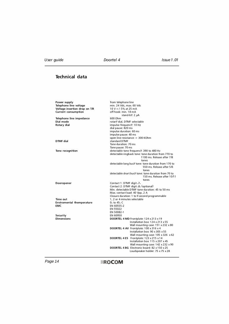
Power supply from telephone lineTelephone line voltage min. 24 Vdc, max. 60 VdcVoltage insertion drop on T/R 10 V +/- 5% at 25 mACurrent consumption off hook: min. 18 mA
stand-by: 2 µATelephone line impedance 600 OhmDial mode rotary dial, DTMF selectableRotary dial impulse frequency: 10 Hz
dial pause: 820 msimpulse duration: 60 msimpulse pause: 40 msopen line resistance: > 300 KOhm
DTMF dial standard DTMFTone duration: 70 msTone pause: 70 ms
Tone recognition detectable tone frequency: 390 to 480 Hzdetectable ringback tone: tone duration from 770 to
1100 ms. Release after 7/8 tones
detectable long busy tone: tone duration from 170 to550 ms. Release after 5/6tones
detectable short busy tone: tone duration from 70 to150 ms. Release after 10/11tones
Dooropener Contact 1: DTMF digit "7"Contact 2: DTMF digit "8" (optional)Min. detectable DTMF tone duration: 45 to 50 msMax. contact load: 40 Vpp, 2 AClosure duration: 1 to 9 second programmable
Time out 1, 2 or 4 minutes selectableEnviromental themperature 0° to 45° CEMC EN 60555-2
EN 55022EN 50082-1
Security EN 60950Dimensions DOORTEL 4 MD Frontplate: 124 x 213 x 19
Installation box: 124 x 213 x 55 Wall mounting case: 151 x 232 x 80DOORTEL 4 AV Frontplate: 100 x 316 x 4
Installation box: 90 x 305 x 55 Wall mounting case: 105 x 326 x 62
DOORTEL 4 ES Frontplate: 123 x 215 x 14 Installation box: 115 x 207 x 45 Wall mounting case: 142 x 232 x 90
DOORTEL 4 BG Electronic board: 82 x 150 x 25 Loudspeaker holder: 75 x 75 x 28
Technical data
User guide Doortel 4 Issue 1.01
Page 15
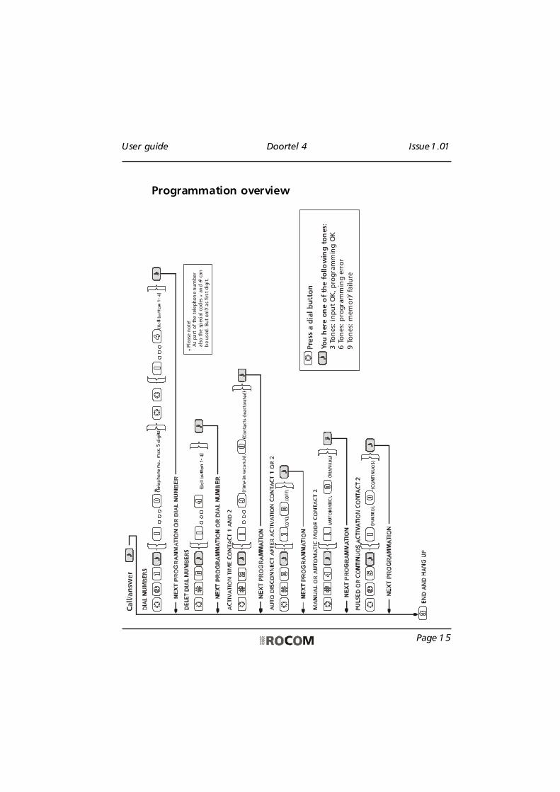
Programmation overview*
Ple
ase
note
! A
s part
of
the t
elephon
e num
ber
a
lso t
he s
pec
ial co
des
* a
nd #
can
b
e use
d. But
only
as
firs
t dig
it.
*
Yo
u h
ere
on
e o
f th
e f
ollo
win
g t
on
es:
3 T
on
es:
in
pu
t O
K,
pro
gra
mm
ing
OK
6 T
on
es:
pro
gra
mm
ing
err
or
9 T
on
es:
mem
ory
failu
re
User guide Doortel 4 Issue 1.01
Page 16
Your dealer:
Made by:
Energie- und Kommunikationssysteme GmbHLessing Str. 20, 63110 Rodgau, Germany
Tel. +49-6106-6600-0 Fax +49-6106-6600-66E-Mail: [email protected]
www.rocom-gmbh.de
© 2
002
ROC
OM
Gm
bH. P
rodu
ct m
ay c
hang
e w
itho
ut n
otic
e. W
e do
not
res
pond
for
any
err
ors
or m
ista
ke in
the
pre
sent
doc
umen
tati
on.
P
rint
ed in
Ger
man
y.