user and maintenance manual e ride...
TRANSCRIPT

USER AND MAINTENANCE MANUAL
E Ride 21
Minuteman International 14N845 U.S. Route 20,Pingree Grove, IL 60140 USAPhone: (800) 323-9420Email: [email protected]: www.minutemanintl.com
Warning:read the instructions
before using the machine
Original instructions


TABLE OF CONTENTS
CHAPTER 1 INTRODUCTION 1-11.1 PURPOSE AND CONTENT OF THE MANUAL 1-11.2 TARGET 1-11.3 HOW TO KEEP THIS MANUAL 1-11.4 IDENTIFICATION DATA 1-21.5 OTHER REFERENCE MANUALS 1-21.6 SPARE PARTS AND MAINTENANCE 1-21.7 MODIFICATIONS AND IMPROVEMENTS 1-2
CHAPTER 2 SAFETY - ACCIDENT PREVENTION 2-12.1 SYMBOLS 2-12.2 GENERAL INSTRUCTIONS 2-12.3 UNPACKING 2-4
CHAPTER 3 MACHINE DESCRIPTION 3-13.1 SCRUBBER-DRYER OPERATION 3-13.2 AGREEMENTS 3-13.3 DESCRIPTION 3-23.4 TECHNICAL CHARACTERISTICS 3-73.5 ELECTRICAL DIAGRAM 3-93.6 ELECTRICAL PROTECTIONS 3-93.7 WASH-AND-DRY MACHINE EQUIPMENT 3-93.8 OPTIONAL ACCESSORIES 3-9
CHAPTER 4 USE 4-14.1 BATTERIES CONTROL / INSTALLATION ON A NEW
WASH-AND-DRY MACHINE 4-14.2 BEFORE STARTING THE WASH-AND-DRY MACHINE 4-24.3 START UP AND STOPPING OF MACHINE 4-44.4 WASH-AND-DRY MACHINE IN OPERATION 4-6
I

4.5 AFTER MACHINE USE 4-64.6 EMPTYING THE TANKS 4-64.7 WASH-AND-DRY MACHINE PUSH/DRAWING MOVEMENT 4-84.8 LONG INACTIVITY OF THE WASH-AND-DRY MACHINE 4-84.9 FIRST PERIOD OF USE 4-8
CHAPTER 5 MAINTENANCE 5-15.1 SCHEDULED MAINTENANCE TABLE 5-15.2 SQUEEGEE CLEANING 5-25.3 CHECKING/SUBSTITUTION OF THE SQUEEGEE RUBBERS 5-35.4 HEIGHT ADJUSTMENT OF SQUEEGEE 5-45.5 BRUSH CLEANING 5-45.6 CYLINDRICAL BRUSH CLEANING 5-55.7 CLEANING THE DETERGENT SOLUTION (OR WATER
FOR WASHING) FILTER 5-65.8 CLEANING THE NOZZLE AND FILTER DETERGENT SOLUTION
SUPPLY TO THE DISC BRUSH 5-85.9 CLEANING THE NOZZLE AND FILTER DETERGENT SOLUTION
SUPPLY TO THE CYLINDRICAL BRUSHES 5-95.10 CLEANING THE DETERGENT FEEDING SYSTEM (OPTIONAL) 5-95.11 BATTERY CHARGE 5-105.12 CHECKING/REPLACING THE FUSES 5-145.13 ASSEMBLY-DISASSEMBLY OF THE SUEEGEE 5-145.14 ASSEMBLY-DISASSEMBLY OF THE DISC BRUSH 5-165.15 CYLINDRICAL BRUSHES ASSEMBLY-DISASSEMBLY 5-17
CHAPTER 6 SAFETY FUNCTIONS 6-16.1 EMERGENCY STOP BUTTON 6-16.2 MICROSWITCH OF DRIVER’S SEAT 6-1
CHAPTER 7 TROUBLESHOOTING 7-1
CHAPTER 8 SCRAPPING 8-1
II

CHAPTER 1INTRODUCTION
1.1 PURPOSE AND CONTENT OF THE MANUAL
The purpose of this manual is to provide the User with allnecessary information to use the machine properly in asafe and autonomous way. It contains information abouttechnical characteristics, operation, machine inactivity,maintenance, spare parts and safety conditions.Before carrying out any procedure on the machine, theOperators and Technicians in charge of the maintenancemust read this manual carefully. Contact Minuteman incase of doubts regarding the interpretation of theinstructions and for any further information.
1.2 TARGET
This manual is intended for the Operator and theTechnicians qualified for the machine maintenance. Theoperators must not carry out operations assigned toqualified technicians. Minuteman declines liability forany damage arising from not observing this prohibition.
1.3 HOW TO KEEP THIS MANUALThe User and Maintenance Manual must be kept near themachine, inside an adequate case, far from liquids andother substances that can cause damage to it.
1-1

1.4 IDENTIFICATION DATAThe Machine Model and Serial Number are marked on theplate on the frame (battery side) and can be read fromthe outside (1, Figure 1-1). This information is useful when requiring machinereplacement parts. Use the following table to write downthe machine identification data for any furtherreference.
1.5 OTHER REFERENCE MANUALSMoreover, the following manuals are available:– Service Manual (that can be consulted at any
Minuteman Service Center)– Spare Part List, supplied with the machine
1.6 SPARE PARTS AND MAINTENANCEAll necessary use, maintenance and repair proceduresmust be carried out by qualified personnel or byMinuteman SERVICE. Only original spare parts andaccessories must be used.Call Minuteman for service or to order spare parts andaccessories, specifying the machine Model and SerialNumber.
1.7 MODIFICATIONS AND IMPROVEMENTS
Minuteman constantly improves its products and reservesthe right to make changes and improvements at itsdiscretion without being obliged to apply such benefits tothe machines previously sold.Any modifications and/or accessory addition mustbe approved and performed by Minuteman.
Figure 1-1
MACHINE model:
MACHINE serial number:
1
1-2

CHAPTER 2SAFETY - ACCIDENT PREVENTION
The following symbols indicate potentially dangeroussituations. Always read carefully this information and takethe necessary precautions to protect people and objects.Cooperation between the Operator and the machine iscritical. No accident prevention program is effectivewithout the total cooperation of the person responsible forthe machine operation. Most of the accidents that mayoccur in a factory, while working or transferring, arecaused by the failure to comply with the simplest prudencerules. A careful and prudent user is the best guaranteeagainst accidents and is the prerequisite to carry out theprevention program.
2.1 SYMBOLS
2.2 GENERAL INSTRUCTIONSSpecific warnings and cautions to inform about potentialdamages to people and machine are shown below.
DANGER!Indicates a dangerous situation (risk ofdeath) for the User.
WARNING!Indicates the risk for people of being injuredand for objects of being damaged.
CAUTION!Indicates a caution or a remark related toimportant or useful functions. Take care ofthe paragraphs marked by this symbol.
READINGConsult the instruction booklet beforeperforming a determined operation.
DANGER!
– Disconnect the battery by means of theappropriate connector before carrying outany maintenance or repair operation.
– This machine must be used by qualified andauthorized personnel only. Children orinfirm people cannot use this machine.
– Keep the battery far from sparks, flamesand incandescent material. During thenormal operation explosive gases aredelivered.
– Do not wear jewelry when working nearelectrical components.
– Do not work under the lifted machine if it isnot securely fixed.
– Do not operate the machine neardangerous, inflammable and/or explosivepowders, liquids or vapours.
– Battery charging produces explosivehydrogen gas. Keep the tank assemblyopen during battery charging and performthe operation only in well-ventilated areasand far from open flames.
2-1

cted e
WARNING!
– Do not use the machine for purposes otherthan those listed in this manual. Use onlyaccessories recommended by themanufacturer Minuteman.
– While using this machine take care not to cause injury or harm to yourself or others.
– Do not let the machine be used as a toy. Payspecial attention when used near children.
– Always protect the machine against thesun, rain and bad weather, both underoperation and in inactivity condition.
– Do not use the machine as a transportvehicle.
– Do not leave the machine unattendedwithout being sure that the machine cannotmove independently.
– Do not leave the machine unattendedwithout removing the key from its housing.
– Do not use the machine in very dusty areas.– Do not use the machine on surfaces with a
gradient greater than 6%.– Do not bump into shelves or scaffoldings, in
particular where there is a risk of fallingobjects.
– Do not let any objects obstruct theair pathways. Do not use the machine if thepathways are blocked; always keep the airpathways free from dust, debris, and othermaterials which could reduce the air flow.
– To avoid the risk of electric shock, do notexpose the machine to rain. Store themachine indoors.
– Do not remove or modify the plates affixedon the machine.
– The machine working temperature must bewithin 0°C - +40°C.
– Storage temperature must be within 0°C -+40°C.
– Humidity range should be within 30% and95%.
– In case of machine malfunctions, reviewChapter 5 (Maintenance) and 7 (Trouble-shooting). Otherwise, requestassistance from an authorized Minutemanservice Dealer.
– Carefully read all maintenance/repairinstructions before carrying out anymaintenance/repair procedure.
– Do not tamper with the machine safetyguards; For your safety, only follow therecommended maintenance instructions.
– Do not wash the machine with pressurizedwater, or with corrosive substances.
– Before using the battery charger, be surethat frequency and voltage values indicatedin the specific Manual correspond to thesystem values.
– Do not recharge the batteries if the powercord or plug is damaged.
– Do not smoke during battery charging.– To reduce the risk of fire, electric shock or
injury, do not leave the machine charging forfor long periods of time. Unplug when connemachine from the wall outlet when not inuse and before maintenance.
2-2

– Do not use the battery charger cable forhauling or transporting the machine. Do notlet the power cord being crushed by a door,pull it over surfaces or sharp corners. Donot run with the machine over the powercord. Keep the cord away from hotsurfaces.
– If the machine is not working properly,damaged, left outdoors or dropped into thewater, ask for the intervention of a servicecenter Minuteman.
– Take all necessary precautions to preventhair, jewels and loose dresses from beingcaught by the machine moving and suctionparts.
– If parts must be replaced, requireORIGINAL spare parts from a Dealer orAuthorized Retailer.
– To ensure the machine proper operationand safety conditions, the authorizedpersonnel or the Service Center must carryout the Scheduled Maintenance detailed inthe related chapter of this Manual.
– If the machine is used according to theinstructions, the vibrations do not causedangerous situations. The machinevibration level is under 2.5 m/s2.
– This machine cannot be used on roads orpublic streets.
– Pay attention to the machine transfers whentemperature is under freezing point. Thewater in the recovery tank or in the pipescould freeze and damage the machine.
– Use the brushes and the disks supplied withthe machine and those specified in theInstruction Manuals. Using other brushes ordisks could reduce safety.
– If lead-acid batteries (WET) are installed inthe machine, do not tilt the machine over 30° to the horizontal plane, to avoid the highlycorrosive liquid escapes from the battery.When you need to tilt the machine formaintenance, remove the batterybeforehand.
– The machine must be not abandoned, atthe end of its useful life, because of thepresence of toxic-harmful materials (batteryacid, oil, etc.), which are subject tostandards that require disposal in specialcenters (see chapter "Scrapping").
2-3

2.3 UNPACKINGTo unpack the Machine carefully follow the instructions onthe packing.When the machine is delivered, check that the packing andthe machine were not damaged during transportation. Ifthe damage is evident, keep the packing and have itchecked by the Parcel Service that delivered it. Call theParcel Service immediately to fill in a request for acompensation for damages.Please check that the following items have been suppliedwith the machine:1. Technical documents:
– Scrubber-dryer Use and Maintenance Manual– Spare Part List
2. ........
2-4

CHAPTER 3MACHINE DESCRIPTION
3.1 SCRUBBER-DRYER OPERATION The scrubber-dryer is used to clean (washing and drying)smooth and solid floor, in civil or industrial environment,under safe operation conditions by a qualified Operator.The scrubber-dryer cannot be used for fitted carpet andcarpet cleaning.
3.2 AGREEMENTSForward, backward, front, rear, left or right are intendedwith reference to the operator’s position with the operator'shands on the handlebar (12, Figure 3-2).
3-1

3.3 DESCRIPTIONControl panel and controls(See Figure 3-1)1. Control panel and controls2. Emergency stop button 3. Display, indicating:
3a. “READY”: wash-and-dry machine ready, or “SITDOWN”: sit on the seat
3b. Total hours of work 3c. Battery state of charge in %3d. Battery state of charge in graphic scale
4. Adjustment buttons (+ and -) of the detergent solutionflow (or of the water for washing) (*)
5. Light indication of the detergent solution flow (orwater for washing)
6. Adjustment buttons (+ and -) of the detergentpercentage according to washing water (optional) (*)
7. Light indication of the detergent percentage(optional).
8. 30-second turbo button for activating the maximumdetergent solution and detergent flow (or water forwashing).
9. 30-second light indication.10. Adjustment button of the maximum wash-and-dry
machine speed (*)11. Wash-and-dry machine instantaneous speed light
indication12. Button for activating the lowering and rotation of the
disc brush (or cylindrical brushes)13. Activated disc brush (or cylindrical brushes) light
indication; the light indication blinks during thepassage from de-activated to activated and viceversa
14. Button for activating the lowering of the squeegeeand water recovery suction.
15. Activated squeegee and suction light indication; thelight indication blinks during passing from de-activated to activated and vice versa
16. Simultaneous activation button for both the squeegeeand suction and the disc brush (or cylindricalbrushes).
17. Activated squeegee, suction and disc brush (orcylindrical brushes) light indication; the lightindication blinks during passing from de-activated toactivated and vice versa
18. Button for activating the reverse motion.Speed is halved compared to the forward motionAn attention sound signal is activated for the activationtime of the reverse motion
19. Reverse motion activated light indication 20. Button for activating the sound attention sound
signal.21. Button for releasing the disc brush.
(*): On starting the wash-and-dry machine through the key,these adjustments are set on previous values.
3-2

Figure 3-1
11
10
12 1418 3c 3a 3d 3b21 20 3
7
6
13
15
17
9
19 16
4
251
8
3-3

External views(See Figure 3-2 and Figure 3-3)
1. Steering-wheel2. Ignition key:
0: offI: on
3. Pedal for starting motion and acceleration4. Detergent solution (or water for washing) level
indicator 5. Front drive and steering wheel 6. Rear wheels7. Disc brush8. Cylindrical brushes9. Squeegee
10a. Detergent solution (or water for washing) tank10b. Water recovery tank
11. Tank covers12. Operator’s seat13. Detergent tank with handle (optional)14. Detergent tank stopper15. Detergent solution (or water for washing) tank
stopper16. Water recovery waste pipe17. Detergent solution (or water for washing) waste pipe18. Battery-holder case19. Blinking light (optional)20. Drinks-holding container (usable only if the blinking
light is not installed)21. Object-holding container (usable only if the detergent
tank is not installed)22. Protection panel of the electric-electronic
compartment23. Detergent solution (or water for washing) filter24. Identification plate / technical data / CE marking
25. Tanks cover lifting handle26. Heel cushion27. Rear wheel cover28. Rear wheel mudguard29. Emergency and parking brake
Figure 3-2
11
10a
10b
97
4
22
2
251
5 29
12
3
26
3-4

Figure 3-3
19141321
15
16
17
18
27 28
20
9
6
8
24
23
3-5
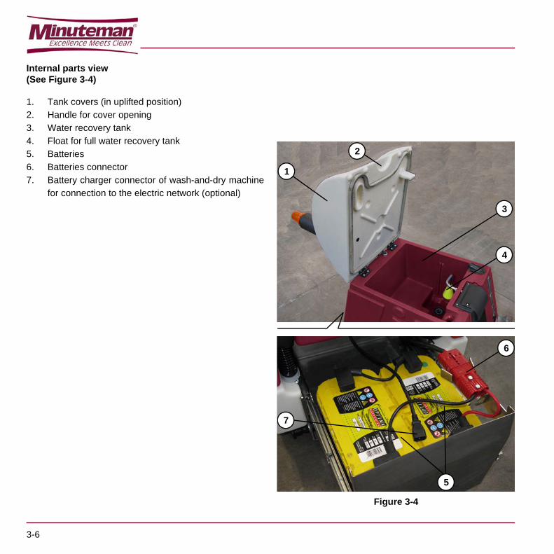
Internal parts view(See Figure 3-4)
1. Tank covers (in uplifted position)2. Handle for cover opening 3. Water recovery tank4. Float for full water recovery tank5. Batteries6. Batteries connector7. Battery charger connector of wash-and-dry machine
for connection to the electric network (optional)
Figure 3-4
1
2
3
4
7
5
6
3-6

3.4 TECHNICAL CHARACTERISTICS
DescriptionE Ride 21
(with one disc brush)
E Ride 21(with two cylindrical
brushes)
Voltage 24V 24V
Washed path 53 cm 51 cm
Suction 1168 mm H2O 1168 mm H2O
Detergent solution tank (or water for washing), capacity 55 L 55 L
Water recovery tank, capacity 55 L 55 L
Disc brush revolutions 175 rpm -
Cylindrical brush revolutions - 830 rpm
Number of disc brushes 1 -
Number of cylindrical brushes - 2
Disc brush pressure 23 Kg -
Cylindrical brushes pressure - 25 Kg
Washing speed 3-5 Km/h 3-5 Km/h
Maximum speed 5 Km/h 5 Km/h
Maximum floor inclination for using the wash-and-dry machine 6 % 6 %
Maximum overcoming inclination of the wash-and-dry machine drive during transfers
25 % 25 %
No. Batteries 2 – 110 Ah 2 – 110 Ah
Inbuilt battery charger Yes (optional) Yes (optional)
Theoretical hour yield 2120 mq/h 2040 mq/h
Estimated hour yield 1270 mq/h 1220 mq/h
Endurance 2.30 h 2.30 h
MIT (Minuteman Injection Tecnology) Yes Yes
MIT, flow 0,4-3,8 L/min 0,4-3,8 L/min
MCS (Minuteman Chemical System) Optional Optional
MCS, ratio 1-5 % 1-5 %
Wash-and-dry machine passage width 65 cm 65 cm
3-7

Wash-and-dry machine body dimensions, with squeegee and brush (length x height x width)
1200 x 1130 x 600 mm 1200 x 1130 x 600 mm
Wash-and-dry machine net weight (without batteries, with empty tanks, without driver)
148 Kg 145 Kg
Wash-and-dry machine gross weight (with batteries, with one full tank, without driver)
~ 250 Kg ~ 247 Kg
Drive motor 400 W 400 W
Disc brush motor 400 W -
Motor cylindrical brushes - 600 W
Motor suction 400 W, 3 stages 400 W, 3 stages
Manufacturing Regulations CE CE
Protection class IPX 4 IPX 4
Level of acoustic pressure A at working position 72.4 dB (A) 72.4 dB (A)
Level of acoustic power A 87.6 dB (A) 87.6 dB (A)
DescriptionE Ride 21
(with one disc brush)
E Ride 21(with two cylindrical
brushes)
3-8

3.5 ELECTRICAL DIAGRAMRefer to the Service manual.
3.6 ELECTRICAL PROTECTIONSFuses– The following fuse (22, Figure 3-2) is placed under
the panel:– Fuse (F3) for protecting auxiliary services (10
A): (2, Figure 4-2)
For the other fuses present on the wash-and-dry machine,refer to the Service manual
3.7 WASH-AND-DRY MACHINE EQUIPMENT
The wash-and-dry machine is supplied with the followingequipment versions:
STD Version:– with squeegee– without disc brush (or cylindrical brushes)– without batteries– without electronic battery charger onboard
B Version:– with squeegee– without disc brush (or cylindrical brushes)– with batteries– without electronic battery charger onboard
OBC Version:– with squeegee– with disc brush (or cylindrical brushes)– without batteries– with electronic battery charger onboard
COMPLETE Version:– with squeegee– with disc brush (or cylindrical brushes)– with batteries– with electronic battery charger onboard
DELUXE Version:– with squeegee– without disc brush (or cylindrical brushes)– without batteries– without electronic battery charger onboard– with heel cushion (26, Figure 3-2)– with wheel covers for rear wheels (27, Figure 3-3)– with wings for rear wheels (28, Figure 3-3)
in addition:The batteries can be of the following types: – lead (WET)– GEL– AGM
3.8 OPTIONAL ACCESSORIESCylindrical brushes of different materials compared to thestandard ones.
Oil-proof squeegee rubber blades.
Front and rear wheels of different materials
Washing detergent feeding system (MCS)
Blinking light.
Filling the detergent solution (or water for washing) tankextractable hose.
Filling the detergent solution (or water for washing) tankquick connection.
For further information on the wash-and-dry machineequipment and the above optional accessories, refer toyour trusted Dealer.
3-9

3-10

CHAPTER 4USE
By means of this Manual, the operator must learn themeaning of these symbols.Do not cover these plates for any reason, in case ofdamage replace them immediately.
4.1 BATTERIES CONTROL / INSTALLATION ON A NEW WASH-AND-DRY MACHINE
Alternatively, the wash-and-dry machine requires:– 2 12V, 110 Ah (WET) batteries – 2 12V, 110 Ah (GEL) batteries – 2 12V, 110 Ah (AGM) batteries
The machine can be supplied as follow:
a) WET or GEL or AGM batteries supplied andalready installed on the machine and ready to beused
b) Without batteries
According to these conditions, operate as describedbelow.
a) WET or GEL or AGM batteries supplied andalready installed on the machine and ready to beused1. The machine is ready to be used.
b) Without batteries2. Buy appropriate batteries (See paragraph
"Technical Characteristics" Apply to batteryqualified retailers to choose and install thebattery.
3. Install and set the machine batteries ServiceManual according to the type of battery, asdescribed in the following paragraph.
WARNING!On some points of the machine there aresome adhesives indicating:–DANGER–WARNING–CAUTION–CONSULTATION
ATTENTIONThe electric components of this machine canbe seriously damaged if batteries are eitherinstalled or connected improperly. Batteriescan be installed by qualified personnel only.Set the machine electronic board and theintegrated battery charger according to thetype of batteries used (WET, GEL, AGMbatteries).Check the batteries for damage beforeinstallation.Disconnect the battery connector or thebattery charger plug.Move the batteries with great care.Install the battery terminal protection capssupplied with the machine.
4-1

4.2 BEFORE STARTING THE WASH-AND-DRY MACHINE
General control 1. Visually check that the wash-and-dry machine is in
good conditions; check that the disc brush (1,Figure 4-1) (or the cylindrical brushes) and thesqueegee (2) are present and in good conditions.
Control of water recovery tank 2. Raise the cover (3, Figure 4-1) with its handle and
check that the water recovery tank is empty,otherwise proceed with the emptying by acting asdescribed in the related paragraph “tanks emptying”.
Water filling of the detergent solution (or water forwashing) tank– The tank can be filled in one of the following ways,
according to the version of the nozzle present on thewash-and-dry machine.
3. (Basic version)Unscrew the stopper (4, Figure 4-1), then introducewater through its nozzle (5).Once the filling is completed, screw the stopper (4).
4. (Version with extractable hose)Unscrew the stopper (4, Figure 4-1), then extract theextractable hose (6) and position its opening (7)under a water tap and fill the tank. Once the filling iscompleted, insert the extractable hose in its place (6,Figure 4-1) and screw the stopper (4).
5. (Version with quick connect stopper) Connect thewater pipe equipped with a proper quick connectionto the stopper (9) quick connection (8, Figure 4-1),then open the pipe tap, and let the water flow into thetank. Upon reaching the full tank, the water flow will
be stopped automatically by the quick connection (8).Remove the water pipe from the quick connection (8).
Addition of detergent in the water for washing tank (Only for the version without automatic detergentfeeding system (MCS))
6. If present, remove the stopper (4, Figure 4-1) andadd the detergent to the clean water present in thetank; follow the dilution instructions indicated on thelabel of the detergent container itself. If the tank is too full, let enough water to flow out soto add the detergent.
Filling of the detergent tank (Only for the version withautomatic detergent feeding system (MCS))
7. If necessary, it is possible to remove the detergenttank from the wash-and-dry machine (10, Figure 4-1),by seizing its handle (11) and raising it.
8. Unscrew the stopper (12).9. Introduce the washing detergent into the tank (10,
Figure 4-1), then screw the stopper (12).10. If removed, reinsert the tank (10, Figure 4-1) to its
place in the wash-and-dry machine.
ATTENTION!The water temperature in the tank must not exceed40 °C (100°F)
ATTENTION!Use a proper detergent for the type ofcleaning to be carried out. Use exclusivelylow foaminess and non-inflammable liquiddetergents; suitable for the wash-and-drymachine to be used.
4-2

Figure 4-1
ATTENTION!Use a proper detergent for the type ofcleaning to be carried out. Use exclusivelyliquid detergents with low foaminess andnon-inflammable; suitable for the wash-and-dry machine to be used.
5
1211
10
4
3
28
7 6
9
1
4-3

4.3 START UP AND STOPPING OF MACHINE
Start up1. Prepare the machine as envisaged in the previous
paragraph.2. Seat up on the machine seat (7, Figure 4-2).3. Turn the start up key (1, Figure 4-2) on “I”; wait a few
seconds until on the display (3) appears the machine-is-ready caption (4) “READY”.
In the event that the start up key is turned (1,Figure 4-2) without being seated on the seat, in thedisplay area (4) appears caption "SIT DOWN" and nofunction of the machine is available.When the display shows indications other than thosedescribed, it is necessary to request action by theMinuteman Assistance Service.
4. Check the state of the battery charges by observingthe percent indication (5, Figure 4-2) and the graphicindication (6).If necessary proceed in charging the batteries; seespecific paragraph of chapter Maintenance.
5. Go to the workplace, by starting up the machine withthe hands on the steering wheel and by pressing thepedal (2, Figure 4-2).
The speed of moving is adjustable from zero to itsmaximum set value, depending on the pressureexerted on the pedal (2, Figure 4-2)
6. If necessary, through the buttons (8, Figure 4-2)adjust the capacity of the detergent solution (or waterfor washing).
7. (Optional) If necessary, through the buttons (9,Figure 4-2) adjust the percentage of the detergent forwashing.
8. If necessary, through the button (10, Figure 4-2)adjust the maximum speed of the machine.
9. To start washing the pavement, activate the discbrush (or cylindrical brushes) through the button (11,Figure 4-2).
10. To start drying of the pavement, activate suctionthrough the button (12, Figure 4-2).
11. To start both washing and drying of the pavement,activate the button (13, Figure 4-2).
12. Start cleaning work by handling through the handsthe steering wheel (14, Figure 4-2) and by drivingforward the machine by pressing appropriately thepedal (2).
Stopping the machine13. Release the pedal (2, Figure 4-2).14. Press the buttons (11, Figure 4-2) or (12) or (13,) to
deactivate and lift the respective active operations.Suction stops a few seconds after activation of therelated button, for sucking all the water present in thepiping.
15. Turn the start up key (1, Figure 4-2) on “0”, and thenextract it.
16. If necessary, proceed with emptying the tanks,operating as described in the specific paragraph.
ATTENTION!Do not turn the start up key (1) without firstseating on the seat (7), since a safety systemconsents use of the machine only when theoperator is seated on the machine seat (7).It is absolutely forbidden to try to mishandlethe above-mentioned seat safety system, orsimulate in any way seating of the operatoron the seat.
ATTENTION!The machine is not suitable to be used onruined, uneven floors.
ATTENTION!Do not leave the machine unattended withoutascertaining that it does not moveautonomously.Do not leave the machine unattended withoutremoving the start up key.
4-4

17. To stop immediately the machine in the event of anemergency, press the button (15, Figure 4-2). To cut out the emergency button (15), turn itclockwise until unhooking it from the lower position.
Figure 4-2
7
14
1
2
158 9
10 11
12
13
4 5 3 6
4-5

4.4 WASH-AND-DRY MACHINE IN OPERATION
1. During operation, check the state of the batteriescharge to avoid flat batteries in inaccessible batteryrecharge points.
2. Check also periodically the residual quantity ofdetergent solution (or water for washing), through itslevel indicator.
3. If the water recovery tank fills during use of the wash-and-dry machine, suction is automatically stopped.To start suction again, it is necessary to empty thewater recovery tank (see related paragraph).
4. If necessary, at the end of the operation, proceed withemptying the tanks (see related paragraph).
4.5 AFTER MACHINE USEAt the end of the work, before leaving the machine:Disconnect the brush in the following way:1. Empty the tank of water recovery, as listed in the
following paragraph.2. Clean the disc brush (or cylindrical brushes) and the
squeegee, as listed in the Maintenance Chapter.3. If necessary, recharge the battery as listed in the
Maintenance Chapter.4. Leave the machine in a dry and clean place, with
brush and squeegee lifted.
4.6 EMPTYING THE TANKSEmptying the tank from water recovery1. Take the wash-and-dry machine to the suitable area
for draining the water recovery, in full compliance ofthe anti-pollution regulations in force.
2. Disengage the hose (1, Figure 4-3) from its seat andraise it beyond the upper edge of the tank until itsarea (2) is water free; then, by keeping it in thisposition, unscrew the stopper (3).
3. Bend manually the hose in the area (2) until obtaininga watertight fold (17); then, by keeping it bent, lowerit on the drain area.
4. Release gradually (in order to avoid undesiredsquirts) the fold (17) by letting the dirty water flow outfrom the tank into the drain area.
5. With the handle (4, Figure 4-3), raise the cover of thetanks (5) and, if necessary, wash the water recoverytank (6); wash also the related lower side (7) of thecover and perimeter gasket (8).Check that the perimeter gasket (8) is whole: ifdamaged, it can jeopardise the good functioning ofthe dirty water suction.
6. Let all the water for washing flow out of the hose (1,Figure 4-3), then screw the stopper (3) and engagethe hose (1) on its seat in the wash-and-dry machine.
Detergent solution (or water for washing) tankemptying7. Take the wash-and-dry machine to the suitable area
for draining the detergent solution (or water forwashing), in full compliance of the anti-pollutionregulations in force.
8. Disengage the hose (10, Figure 4-3) from its seatand raise it beyond the upper edge of the tank until itsarea (11) is free from water; then, by keeping it in thisposition, unscrew the stopper (12).
9. (Only for optional hose that can be pressed in thearea (11)): Bend manually the hose in the area (11)until obtaining a watertight fold (17); then, by keepingit bent, lower it on the drain area.Release gradually (in order to avoid undesiredsquirts) the fold (17) by letting the detergent solution(or water) flow out from the tank into the drain area.
WARNING!Do not damage the float (9, Figure 4-3)
4-6
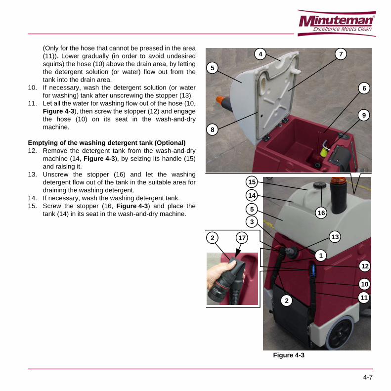
(Only for the hose that cannot be pressed in the area(11)). Lower gradually (in order to avoid undesiredsquirts) the hose (10) above the drain area, by lettingthe detergent solution (or water) flow out from thetank into the drain area.
10. If necessary, wash the detergent solution (or waterfor washing) tank after unscrewing the stopper (13).
11. Let all the water for washing flow out of the hose (10,Figure 4-3), then screw the stopper (12) and engagethe hose (10) on its seat in the wash-and-drymachine.
Emptying of the washing detergent tank (Optional)12. Remove the detergent tank from the wash-and-dry
machine (14, Figure 4-3), by seizing its handle (15)and raising it.
13. Unscrew the stopper (16) and let the washingdetergent flow out of the tank in the suitable area fordraining the washing detergent.
14. If necessary, wash the washing detergent tank.15. Screw the stopper (16, Figure 4-3) and place the
tank (14) in its seat in the wash-and-dry machine.
Figure 4-3
15
14
5
2 11
10
12
16
4
8
7
6
9
5
3
172
1
13
4-7

4.7 WASH-AND-DRY MACHINE PUSH/DRAWING MOVEMENT
When it is not possible to use the wash-and-dry machinedrive, it is possible to move it by pushing it manually.
4.8 LONG INACTIVITY OF THE WASH-AND-DRY MACHINE
If it is intended not to use the wash-and-dry machine for aperiod longer than 30 days, it is appropriate to perform thefollowing operations:1. Carry out what is indicated in paragraph "After Use of
the Wash-and-dry Machine".2. Empty the detergent solution (or water for washing)
tank by acting as described in the related paragraph.3. Empty the washing detergent tank (optional) by
acting as described in the related paragraph. 4. Disconnect the connector of the batteries, by acting
as described further down.Remove the left pin (1, Figure 4-4), then rotate it byhalf turn, and block it in the removed position.Remove the right pin (2, Figure 4-4), then removethe battery holder case (3) by the handles (4).Disconnect the connector (5) of the batteries. Insertagain the battery holder case in its seat (3, Figure 4-4) and let it engage to the retainer (2) and retainer (1)after unblocking it.
5. Clean the detergent feeding system (optional), byacting as described in chapter “Maintenance”.
4.9 FIRST PERIOD OF USEAfter the first period of use (first 8 hours) it is necessary tocheck that the fixing and connecting elements are correctlyfixed, that the visible parts are integral and that there areno leakages.
Figure 4-4
ATTENTION!The wash-and-dry machine is not suitable tobe pushed on floors with excessive slopes;precautions must be taken in advance inrelation to the wash-and-dry machine (grossweight with 50 liters of water in tanks: about250 Kg)
4
3
1
5
3
4
2
4-8

CHAPTER 5MAINTENANCE
The machine proper and safe operation is guaranteed bya careful and constant maintenance.The following table sums up the scheduled maintenance.The indicated periods can be subjected to variationsaccording to working conditions. These must be defined bythe person in charge for the maintenance.
All periodic or extraordinary maintenance operations mustbe performed by skilled personnel, or by an authorizedService Center.
This Manual contains the Scheduled Maintenance Tableand describes only the easiest and most commonmaintenance procedures.
WARNING!The operations must be carried out with themachine off and the battery disconnected.Moreover, read carefully the instructions inthe Safety chapter before performing anymaintenance operation.
REMARK:For other maintenance procedures containedin the Scheduled Maintenance Table see thespecific “Service Manual” that can beconsulted at any Service Center.
5.1 SCHEDULED MAINTENANCE TABLE
(1): and after the first 8 working hours(2): maintenance, falling within the competence of a Minuteman Authorized Service Center
OperationDaily, after using the
wash-and-dry machine
Monthly or every 100
hours
Half-yearly or every 400
hours
Yearly or every 800 hours
Squeegee cleaning
Disc brush cleaning (or cylindrical brushes)
Battery charge
Squeegee rubber blades check/replacement
Cleaning of the detergent solution (or water for washing) filter
Cleaning of nozzles and filters
Screws and nuts tightening check (1)(2)
Check of HEPA suction filter (2)
Brushes rotation belt check/replacement (2)
Drive chain check/replacement (2)
5-1

5.2 SQUEEGEE CLEANING
1. If necessary, remove the squeegee (See procedurein the related paragraph).
2. Wash and clean the squeegee (1, Figure 5-1); inparticular, clean the dirt and debris in the spaces (2)and hole (3). Check that the front rubber blade (4)and the rear rubber blade (5) are whole and do notshow cuts or tears, otherwise replace them (seeprocedure in the related paragraph).
3. If removed, replace the squeegee (See procedure inthe related paragraph).
Figure 5-1
NOTETo obtain a good floor drying, the squeegeemust be cleaned and the rubber blades mustbe in good conditions.
ATTENTION!The use of work gloves is recommendedduring the squeegee cleaning due to thepossible presence of sharp debris.
22 5
1
3
41
5-2

5.3 CHECKING/SUBSTITUTION OF THE SQUEEGEE RUBBERS
1. Disassemble and clean the squeegee, by operatingas described in the specific paragraph.
2. Check that the front rubber (1, Figure 5-2) and therear rubber (2), are whole and are without cuts andtears, otherwise substitute them, as described below.Check also that the front edge (3) of the rear rubber(2) is not worn out; otherwise turn upside-down thisrubber, by bringing in its place one of the other threeedges, if still whole. Should also the other threeedges be worn out, substitute the rubber, byoperating as described below:– Substitute (or turn upside-down) the rear rubber
(2, Figure 5-2) after having released the stop(4), unhooked the eccentric (5), and removedthe stop band (7) by releasing them from thedowels with nut (6); finally, refit the rubber byoperating in reverse order with respect to theremoval.
– Substitute the front rubber (1, Figure 5-2) afterhaving unscrewed the nuts (8) and removed thestop band (9); finally, refit la rubber by operatingin reverse order with respect to the removal.
3. Refit the squeegee by operating as described in thespecific paragraph.
4. If necessary, carry out the height Adjustment of thesqueegee by operating as described in the followingparagraph.
Figure 5-2
3
6
7
5
75
4
6
8
2
9 1
5-3
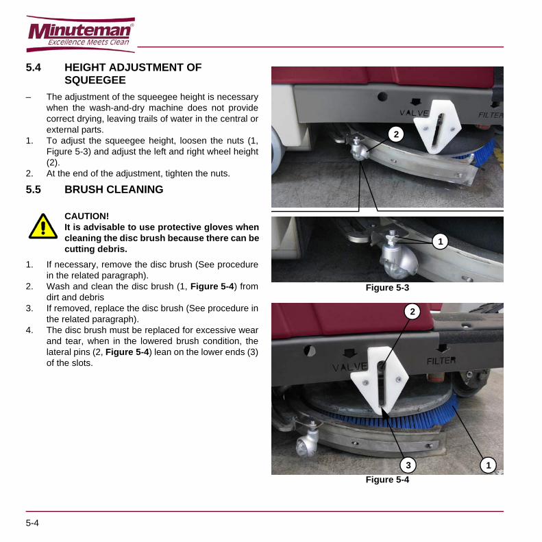
5.4 HEIGHT ADJUSTMENT OF SQUEEGEE
– The adjustment of the squeegee height is necessarywhen the wash-and-dry machine does not providecorrect drying, leaving trails of water in the central orexternal parts.
1. To adjust the squeegee height, loosen the nuts (1,Figure 5-3) and adjust the left and right wheel height(2).
2. At the end of the adjustment, tighten the nuts.
5.5 BRUSH CLEANING
1. If necessary, remove the disc brush (See procedurein the related paragraph).
2. Wash and clean the disc brush (1, Figure 5-4) fromdirt and debris
3. If removed, replace the disc brush (See procedure inthe related paragraph).
4. The disc brush must be replaced for excessive wearand tear, when in the lowered brush condition, thelateral pins (2, Figure 5-4) lean on the lower ends (3)of the slots.
Figure 5-3
Figure 5-4
CAUTION!It is advisable to use protective gloves whencleaning the disc brush because there can becutting debris.
2
1
13
2
5-4

5.6 CYLINDRICAL BRUSH CLEANING
1. Remove the cylindrical brushes (See procedure inthe related paragraph).
2. Wash and clean the cylindrical brushes from dirt anddebris.
3. Wash and clean the cylindrical brushes cases too (1,Figure 5-5). Check that the drive hubs (2) of thecylindrical brushes are free from dirt debris or twistedobjects (ropes, etc.).
4. Replace the cylindrical brushes (See procedure in therelated paragraph).
5. The cylindrical brushes must be replaced forexcessive wear and tear, when in the lowered brushcondition, the lateral pins (1, Figure 5-5) lean on thelower ends (2) of the slots.
Figure 5-5
Figure 5-6
CAUTION!It is advisable to use protective gloves whencleaning the cylindrical brush because therecan be cutting debris.
2 1
1
2
5-5

5.7 CLEANING THE DETERGENT SOLUTION (OR WATER FOR WASHING) FILTER
1. Ascertain that the wash-and-dry machine cannotmove autonomously.
2. By acting on the wash-and-dry machine controls,lower the squeegee and the disc brush (or cylindricalbrushes), then rotate the ignition key on “0” andextract it (see chapter Use).
3. Close the water/detergent solution flow tap (1,Figure 5-7) by acting on the right side of the wash-and-dry machine.
4. Unscrew and remove the filter transparent cover (2).5. Remove the filter (3) from the transparent cover (4).6. Clean the filter (3) and the transparent cover (4).7. Replace the filter (3) in its transparent cover case (4).8. Screw the filter transparent cover to its seat (2).9. Open the tap (1).10. Rotate the ignition key on “I” and wait for the
squeegee and disc brush (or cylindrical brushes)lifting, then rotate the ignition key on “0” and extract it.
5-6

Figure 5-7
2
2
1
4
3
5-7

5.8 CLEANING THE NOZZLE AND FILTER DETERGENT SOLUTION SUPPLY TO THE DISC BRUSH
1. Ascertain that the wash-and-dry machine cannotmove autonomously.
2. Remove the brush (See procedure in the relatedparagraph).
3. By acting on the coupling hub (1, Figure 5-8) of thebrush, unscrew the ring nut (2) and recover thenozzle (3) and the gasket (4).
4. Remove the filter from its seat (5).5. Clean the nozzle (3) and the filter (5).6. Replace the filter correctly (5) in its case.7. Place the nozzle (3) and the gasket (4) in their seat
and then screw the ring nut (2).8. Replace the brush (See the procedure in the related
paragraph).
Figure 5-8
2
1
3
2
3
4
5
5-8

5.9 CLEANING THE NOZZLE AND FILTER DETERGENT SOLUTION SUPPLY TO THE CYLINDRICAL BRUSHES
1. Ascertain that the wash-and-dry machine cannotmove autonomously.
2. By acting on the wash-and-dry machine controls,lower the cylindrical brushes, then rotate the ignitionkey on “0” and extract it (see chapter Use).
3. By acting on the front part of the cylindrical brush-holder head, unscrew the ring nut (1, Figure 5-9) andrecover the nozzle (2) and the gasket (3).
4. Remove the filter from its seat (4).5. Clean the nozzle (2) and the filter (4).6. Replace the filter correctly (4) in its case.7. Place the nozzle (2) and the gasket (3) in their seat
and then screw the ring nut (1).8. Rotate the ignition key on “I” and wait for the lifting of
the cylindrical brushes, then rotate the ignition key on“0” and extract it.
5.10 CLEANING THE DETERGENT FEEDING SYSTEM (OPTIONAL)
1. Empty and clean the washing detergent tank, byacting as described in the related paragraph.
2. Put about one litre of clean water into the washingdetergent tank.
3. Use the wash-and-dry machine by simulating thewashing activity, for the time necessary to clean thedetergent feeding system (15-30 minutes), byadjusting the clean water and “detergent” flows to themaximum values.
4. Finally, remove the residual water from the washingdetergent tank.
5. If necessary, perform the other intended procedures“After use of the wash-and-dry machine” (See therelated paragraph).
Figure 5-9
2 134
1
5-9

5.11 BATTERY CHARGE Battery charge for wash-and-dry machines without onboard battery charger
1. Take the wash-and-dry machine to the area suited forrecharging the batteries.
2. Ascertain that the wash-and-dry machine cannotmove autonomously. Rotate the ignition key on “0” and extract it.
3. By acting of the rear side of the wash-and-drymachine, remove the left pin (1, Figure 5-10), thenrotate it by half turn, and block it in the removedposition.
4. Remove the right pin (2, Figure 5-10) and, carefully,remove completely the battery holder case (3) by thehandles (4), then engage the pin (2) on the relatedlocking hole of the extracted case.
5. Only for lead batteries (WET): – check the correct electrolyte level in the
batteries (7, Figure 5-10); if necessary, restoreit through the stoppers (8).
– let all the stoppers (8) open for the nextrecharge.
– clean (if necessary) the upper surface of thebatteries.
6. Check the suitability of the battery charger to be usedby referring to the instructions of the battery chargeritself. The nominal voltage of the battery chargermust be equal to 24V.
7. Disconnect the connector of the batteries (5,Figure 5-10).
8. Connect the connector (6, Figure 5-10) to theexternal battery charger.
9. Connect the battery charger to the electrical network.The charge of the batteries has started.
10. At the end of the recharge, disconnect the batterycharger from the electric network and the batteryconnector (6, Figure 5-10).
11. (only for lead batteries (WET)) Check the correctelectrolyte level in the batteries, then close all thestoppers (8, Figure 5-10).
CAUTION!Keep the batteries charged make their life lastlonger.
CAUTION!When the batteries are discharged, rechargethem as soon as possible, as that conditionmakes their life shorter.Check for battery charge at least once aweek.
CAUTION!For machines not equipped with on boardbattery charger, the battery charger must beappropriate for the battery installed on themachine.
WARNING!Battery charging of WET batteries producesexplosive hydrogen gas. Charge the batteriesonly in well-ventilated areas and far fromnaked flames.Do not smoke during battery charging.Keep the tank assembly open whilerecharging the battery.
WARNING!Pay attention during battery rechargingbecause there can be battery liquid leakages.The battery liquid is corrosive. If it comes incontact with the skin or eyes, rinsethoroughly with water and consult aphysician.
5-10
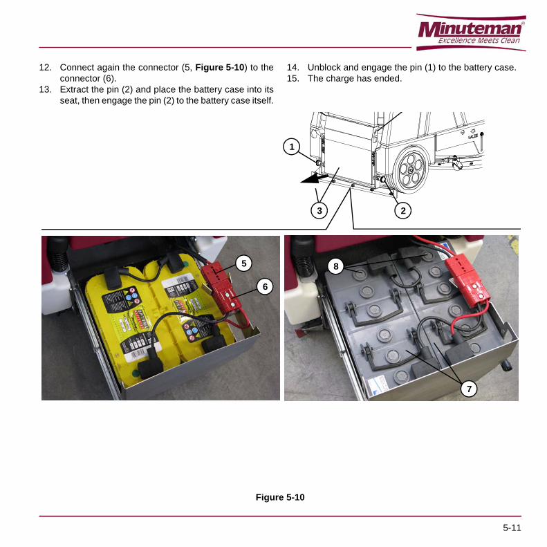
12. Connect again the connector (5, Figure 5-10) to theconnector (6).
13. Extract the pin (2) and place the battery case into itsseat, then engage the pin (2) to the battery case itself.
14. Unblock and engage the pin (1) to the battery case.15. The charge has ended.
Figure 5-10
8
7
5
6
1
3 2
5-11

Battery charge for wash-and-dry machines with onboard battery charger (optional)
1. Take the wash-and-dry machine to the area suited forrecharging the batteries.
2. Ascertain that the wash-and-dry machine cannotmove autonomously.
3. By acting on the rear side of the wash-and-drymachine, remove the left pin (1, Figure 5-12), thenrotate it by half turn, and block it in the removedposition.
4. Remove the right pin (2, Figure 5-12) and, carefully,remove completely the battery holder case (3) by thehandles (4), then engage the pin (2) on the relatedlocking hole of the removed case.
5. Only for lead batteries (WET):– check the correct electrolyte level in the
batteries (7, Figure 5-12); if necessary, restoreit through the stoppers (8).
– let all the stoppers (8) open for the nextrecharge.
– clean (if necessary) the upper surface of thebatteries.
6. Connect the connector (5) to the electrical network,after checking that the nominal voltage of the networkis that envisaged for the charge of the wash-and-drymachine (Refer to the technical data plate of theletter). The charge of the batteries has started.
7. The charge has ended when on the display (1,Figure 5-11) appears “100 %” and all the bars are full(2).
8. Disconnect the electrical connection (5, Figure 5-12)from the network.
9. (only for lead batteries (WET)) Check the correctelectrolyte level in the batteries, then close all thestoppers (8, Figure 5-12).
10. Extract the pin (2, Figure 5-12) and place the batterycase into its seat; then engage the pin (2) to thebattery case itself.
11. Unblock and engage the pin (1, Figure 5-12) to thebattery case.
12. The charge has ended.
Figure 5-11
&
NOTEWhen the battery charger is connected to thenetwork, all the functions of the wash-and-dry machine are automatically excluded.
1 2
5-12

Figure 5-12
2
4
1
7
4
3
5
8
5-13

5.12 CHECKING/REPLACING THE FUSES1. Ascertain that the wash-and-dry machine cannot
move autonomously.2. Rotate the ignition key on “0” and extract it.3. Disconnect the connector from the batteries, by
acting as described further down.Remove the left pin (1, Figure 5-14), then rotate it byhalf turn, and block it in the removed position.Remove the right pin (2, Figure 5-14), then removethe battery holder case (3) by using the handles (4).Disconnect the connector of the batteries (5).
4. Raise the cover (5, Figure 5-15), remove the panel(1) by seizing it on the hold (3) and raising it todisengage it from the retainers (4). Close the cover(5).
5. Check / replace the fuses:– 10A Fuse for protecting auxiliary services (2,
Figure 5-15)6. Place the panel into its seat (1, Figure 5-15) and
engage the retainers (4).7. Connect the connector of the batteries (5, Figure 5-
14).8. Replace the batteries case to its seat (3, Figure 5-14)
and engage it to the retainer (2) and retainer (1) afterunblocking it.
5.13 ASSEMBLY-DISASSEMBLY OF THE SQUEEGEE
Disassembly
1. Ascertain that the wash-and-dry machine cannotmove autonomously.
2. Rotate the ignition key on “0” and extract it.3. By acting of the left side of the wash-and-dry
machine, with the squeegee in raised position, moveslightly the squeegee outwards (1, Figure 5-13), thenloosen its fastening knob (2).
4. Disconnect the suction pipe (3, Figure 5-13) from thesqueegee.
5. Remove the squeegee (1).Assembly
6. Assemble in the reverse order with respect todisassembly
Figure 5-13
1 2
3
5-14

Figure 5-14
Figure 5-15
5
3
4
3
1
4
2
4
4
3
144
2
4
4
5
5-15

5.14 ASSEMBLY-DISASSEMBLY OF THE DISC BRUSH
Disassembly1. Ascertain that the wash-and-dry machine cannot
move autonomously.2. Sit on the wash-and-dry machine seat and rotate the
ignition key (1, Figure 5-16) on “I”, then wait for a fewseconds so that on the display (3) appears caption (4)“READY” indicating that the wash-and-dry machine isready for use.
3. Press the button (5, Figure 5-16) to release the brushand wait for a few seconds that the wash-and-drymachine releases the brush after activating it.
4. Rotate the ignition key (1, Figure 5-16) on “0” andthen extract it.
5. Move slightly the squeegee (6, Figure 5-16) andrecover the disc brush (7).
Assembly6. Ascertain that ignition key (1, Figure 5-16) is on “0”.7. Ascertain that the coupling hub of the disc brush is in
the raised position.8. Place the disc brush (7, Figure 5-16) below the
wash-and-dry machine, by centring it on the couplinghub.
9. Sit on the seat and rotate the ignition key (1,Figure 5-16) on “I”, and wait for a few seconds sothat on the display (3) appears caption (4) “READY”indicating that the wash-and-dry machine is ready foruse.
10. Press the brush lowering and rotation (8, Figure 5-16) activation button.
11. Press slightly and only for an instant the pedal (2, Fig.R), by determining the lowering of the hub that willcouple the brush. In case of non-coupling of the brush, get out of thewash-and-dry machine and reposition the brush onthe coupling hub which will have remained lowered(therefore, the alignment operation will be facilitated).
12. Repeat the operations described in the previouspoints 9, 10 and 11.
13. Rotate the ignition key (1, Figure 5-16) on “0” andthen extract it.
Figure 5-16
84
5
3
1
6
2
7
5-16

5.15 CYLINDRICAL BRUSHES ASSEMBLY-DISASSEMBLY
Disassembly1. Ascertain that the wash-and-dry machine cannot
move autonomously.2. By operating on the wash-and-dry machine controls,
lower the cylindrical brushes then rotate the ignitionkey on “0” and extract it (see the chapter Use).
3. By operating on the right side of the wash-and-drymachine, release the retainers and cam (1, Figure 5-17).
4. Remove the cover (1, Figure 5-18) by disengagingthe supports (2) from the cylindrical brushes (3).
5. Extract the cylindrical brushes (3, Figure 5-19).
Figure 5-17
Figure 5-18
Figure 5-19
1
1
3
2
12
3
1
1
5-17

Assembly6. Place the cylindrical brushes in their seat (1,
Figure 5-20) by ensuring to engage their pentagonalseat (2) in the related hubs (3).
7. Proceed with the assembly by operating in thereverse order with respect to disassembly.
Figure 5-20
1 3
12
5-18

CHAPTER 6SAFETY FUNCTIONS
The wash-and-dry machine is equipped with safetyfunctions described below.
6.1 EMERGENCY STOP BUTTONIt is placed on the control panel and controls, in position (2,Figure 3-1); it can be easily accessed by the operator; itmust be pressed in situations of immediate necessity tostop every function of the wash-and-dry machine. It isdisabled by rotating it clockwise.
6.2 MICROSWITCH OF DRIVER’S SEATIt is located inside the driver’s seat and does not allow anyfunction of the wash-and-dry machine if the operator is notseating on his seat.
6-1

6-2

CHAPTER 7TROUBLESHOOTING
PROBLEM PROBABLE CAUSE SOLUTION
No light indicators light up on the panel;the motors do not work
Battery connector (5, Figure 3-4)disconnected
Connect it
Batteries completely flat Charge them
The emergency stop button (2,Figure 3-1) remains depressed
Press it
The water recovery drain is insufficient
Dirty squeegee (9, Figure 3-2) or wornout or damaged squeegee rubberblades
Clean the squeegee or turn/replace the rubber blades
Tank cover not correctly closed orinefficient gasket (8, Figure 4-3)
Close the cover correctly.Clean/replace the gasket
The water recovery drain is inexistent
The water recovery tank is full. Empty it. Empty it
Flexible hose (3, Figure 5-13)disconnected from the squeegee.
Connect it
Insufficient flow of the detergent solution(or water for washing) to the disc brush(or cylindrical brushes)
Dirty detergent solution (or water forwashing) filter (24, Figure 3-2)
Clean it
Dirty detergent solution (or water forwashing) outlet nozzle
Clean it
Dirty detergent solution (or water forwashing) tanks Clean it
Clean it
7-1

For further information, contact Minuteman Service Centers, where the Service Manual is available.
Lack of detergent solution (or water forwashing) flow to the disc brush (orcylindrical brushes)
Empty detergent solution (or water forwashing) tank
Fill it
Obstructed detergent solution (or waterfor washing) (2, Figure 5-7) filter
Clean it
Obstructed detergent solution (or waterfor washing) outlet nozzle
Clean it
Deficiency/lack of the washing detergentflow to the disc brush (or cylindricalbrushes)(For wash-and-dry machine with MCSoptional detergent feeding system)
Too low percentage (%) of detergentflow set
Increase it
Obstructed detergent feeding systemClean it
The squeegee leaves trails of dirt on thefloor
Debris present below the squeegeerubber blades
Clean the squeegee
Squeegee rubber blades worn out,chipped, or torn
Turn them/replace them
The squeegee does not contactcorrectly
Adjust the height of thesqueegee contact wheels
The disc brush (or cylindrical brushes)does not clean
Excessively worn out brushes and donot touch the floor: check.Check the pins (2, Figure 5-4) or thepins (1, Figure 5-6)
Replace the brushes
PROBLEM PROBABLE CAUSE SOLUTION
7-2

CHAPTER 8SCRAPPING
Have the machine scrapped by a qualified dismantler.Before scrapping the machine, remove the followingcomponents:– Battery– Brush– Hoses and plastic parts– Electric and electronic components(*): In particular, for scrapping electrical and electronicparts, refer to the local Minuteman Head Office.
ATTENTION!This wash-and-dry machine must not bedisposed of with other household waste atthe end of its lifecycle.To avoid possible environmental or healthdamages caused by an inappropriate wastedisposal, the user is advised to separate thisproduct from other types of disposals andrecycle it in a responsible manner in order tofavour the sustainable reuse of the materialresources.
8-1

“Excellence Meets Clean”
Minuteman®, Minuteman International, Inc. · 14N845 U.S. Route 20 · Pingree Grove, Illinois 60140 · USAPhone: 800-323-9420 · Website: www.minutemanintl.com · Email: [email protected]
A Member of the Hako Group
E Ride 21 Scrubber #988748UM, Rev. *.1, 09/13