user & programming manual - dasica
TRANSCRIPT

USER & PROGRAMMING
MANUAL No. A-12705
RapidWrapper 2000
SW1100/SW2100/SW3100 Systems
May 2001

1
JDV PRODUCTS INC. User and Technical Manual
Table of contents
1.0 SW1100/SW/2100/SW3100 Components List 1.1 Setting up the SW1100 1.2 Setting up the SW2100/SW3100 X-Y Wiring Table 1.3 Connecting the interfaces. 2.0 Software installation. 2.1 Operator interface. 3.0 Operation. 3.1 Zero set and Recovery Operations. 4.0 Programming 5.0 Operation tutorial. 6.0 Maintenance. 7.0 Suggested spare parts list. 8.0 Appendixes.

2
JDV PRODUCTS INC. User and Technical Manual
1.0 SW1100/SW2100/SW3100 Systems Components List.
Installation of the JDV wire wrapping positioning systems is simple and straightforward. The system consists of the following: 1. A-12705 Use & Programming Manual and tutorial disk. 2. SWC-2000 Controller unit and JDV Rapid Wrapper 2000 software. 3. SWS-2000 or Customer Supplied Computer system. 4. Numeric keypad. 5. Power cable, Interface cable and Y connector. 6. One of the following tables:
a. SWT 1100 b. SWT 2100 c. SWT 3100
7. SWB40 Wire bin. 8. Inch hexagon wrench set.

3
JDV PRODUCTS INC. User and Technical Manual
1.1 Setting up the SW1100
1. The machine must be setup on a rigid table. An unstable table causes Operator fatigue if the machine is constantly shaking after each movement.
2. Place the SWT 1100 X/Y table on the selected workbench. The adjustable feet under the table should be used for leveling.
3. Place the SWC-2000 Electronic Controller unit to the left or right side of the X/Y table.
4. Place the computer monitor on top of the SWB-40 wire storage bin.
5. Attach the keypad bracket assembly to the X/Y table. The keypad may be mounted on either side of the X/Y table for the operator's convenience.
6. Place the SWS-2000 computer and SWC-2000 controller at a convenient location, follow the label directions at the rear of the computer and controller for connecting the various equipment cables. The -Y- connector connects to the computers' keyboard port and receives input from the keyboard and the numeric keypad. Com1 connects to the controllers' phone style socket. The 14 pin connector cable connects the controller to the wiring table. Connect PCI mouse, VGA monitor and speakers. 7. Set the computer voltage selector switch to appropriate input voltage before connecting power cord. Use the 115 setting for voltages 110 to 120 VAC, and the 230 setting for voltages 220 to 240 VAC. 8. The controller requires 115 VAC input. 9. See Appendix –A- figure 1 for suggested work-station lay out.

4
JDV PRODUCTS INC. User and Technical Manual
1.2 Setting up the SW2100/SW3100 X-Y Wiring Table
1. Before connecting the components the of either the SWT 2000 or SWT 3000 series wrap systems, the -Y- carrier and front cover sub-assembly (removed for shipping) needs to be remounted in place. Reassemble as outlined below and shown in appendix –A-, fig.2.
a. Remove the four 6-32 screws (ref –A-) from the X-carrier. (ref. H.) These are
used for later re-attachment of the front cover. b. Place the –Y- axis assembly close enough to the –X- carrier and connect the two micro-switch wires to the terminal block on top of –X- carrier ref. -H-. Connect black to black, red to red. c. With the pointer on the left hand side, carefully re-install the –Y- axis
assembly onto the –X- carrier. Apply grease if necessary to the two 1/2 “ shaft holes, to facilitate assembly and make sure that the servo clamp is loosely mounted to the top of coupling –F-. The lead screw –C- needs to be held in place during assembly and will fit into the coupling –F- once the two shafts –B- are seated in the bottom counter bores.
d. Re-attach the front cover using the four 6-32 screws removed in step (a.)
Four end holes only.
e. Tighten two 6-32 set screws used to secure the shafts in place. These are Accessible through center holes –e- in the cover and require a .050” Allen key.
f. Position lead screw to allow approximately 1/8” end play with top plate
-D- and tighten servo clamp.
g. Remove one ¼-20 cap screw from upper left hand corner of –U- channel and six 8-32cap screws. Position Frame –I- so that the large clearance hole in one of the inside corners fits over the ¼-20 screw head on the upper right corner of the –U- channel. Fasten the –U- channel with the screws previously removed.
h. Use the adjustable feet to level machine.
i. Attach the support struts to secure the frame to table-top. Plumb both sides vertical before tightening.

5
JDV PRODUCTS INC. User and Technical Manual
j. Arrange the computer, wire bin, controller and other accessories to suit Personal preferences. See appendix –A- fig.1 for suggested arrangement.
1.3 Connecting the interfaces
See appendix –A- fig. 3
a. Key-board and numeric key pad connect to (Y adapter.) b. Y adapter connects to processor key-board port. c. Mouse connects to PS2 port. d. Com-1 connects to telephone style jack at rear of controller. e. 14 pin cable connector from rear of controller to SW table input. f. Speaker connections. g. Monitor port h. Processor power cable (Verify appropriate voltage setting at the rear of
Processor, before turning on.) i. Controller power cable. (115 VAC.)
Note: Verify all connections and power settings before turning on the equipment.

6
JDV PRODUCTS INC. User and Technical Manual Note: If Computer system purchased from JDV software is preloaded. Therefore you may skip this section.
2.0 Software Installation.
BIOS Setup 1. At startup, press <DEL> to enter BIOS setup. 2. Under "Power Management", disable ACPI 3. Exit BIOS, and boot into Windows. Initial Windows Startup 1. Under “User Info” 2. Name: RapidWrapper2000 3. Company: (Leave blank) 4. Enter ID from WIN98 CD. Window Setup 1. Resolution: 800 X 600 2. Wallpaper: Clouds-stretched 3. Small Icons 4. List 5. Show Details 6. Show Hidden Files 7. Power Management: Enter “never” for “System Standby”, “Monitor Off”, and “Hard
Disk Off” Software Installation 1. Install VB5 from the CD. 2. Uninstall VB5 using Windows "Add/Remove Programs" 3. Install RW2000 from the floppies. Install-directory: c:\JDV 4. From “Default Disk”, run Install. 5. Create shortcut to c:\JDV\jdv.exe 6. Change icon. Choose icon from c:\windows\system\shell32.dll 7. Edit shortcut name to RapidWrapper 2000 8. Line up icon.
7
JDV PRODUCTS INC. User and Technical Manual
2.1 Operator interface.
The RapidWrapper 2000 Operators’ interface, follows standard windows convention for the display and activation of tool buttons and pull down menus.
1. Passwords . The default password is JDV. Passwords are case sensitive and can be changed, modified or deleted by clicking on the security pull down menu. Access privilege at the administrator level is required to make changes or additions.
2. File Pull Down menu.
Sample and tutorial files are located in the JDV directory. We strongly recommend the creation of one or more project subdirectories to store the working programs.
3. Mode Pull Down menu.
a. Run mode is used for program execution. b. Jog mode is used primarily during set up, for non-programmed movements
of the X and Y carriages. Jogging movements are not tracked by the system and in all cases require a “zero” reset.
c. Supervisor mode requires access privileges of Supervisor or higher. It is used to reset the program pointer to any desired position in the program and continue execution from that point.
d. ReStart mode is used to continue an unfinished job after a shut down or emergency stop. The program tracks the last completed position and permits a program restart to that position, and continuation of the remaining program steps. (Machine must be at work zero position when invoking ReStart.)
4. Security Pull Down menu.
4.1. Login (Self explanatory.) 4.2. Logout (Self explanatory.) 4.3. Administration. Is used to access the security screen. System Administrators, Supervisors and Operators as well as the passwords are entered on this screen by anyone with Administrator access privilege.
5. Configuration Pull Down menu. Except for the “Step Factor,” the default
Configuration parameters are satisfactory for all wire wrapping operations. If necessary, the customer can change these parameters to better suit his needs. However, any changes should be made one at a time and the appropriate auto.101 or auto.102 should be run after each change to make sure the machine returns to zero after each run. This is an open loop system and if acceleration, deceleration or run speeds are set too high, the machine will miscount the steps and positioning errors will occur.
8
JDV PRODUCTS INC. User and Technical Manual
The default parameters can be reset manually or by running the install program in the “Default data files” floppy disk.
5.1 Step Factor. A step factor of 5.0 is used for programs using the OKI format. A step factor of 2.0 is used for programs using inch units for positioning. See section 5.0 par. 2.2 for more information. 6. User Prompt. Provides the Operator with information relevant to the current wiring position and any instruction deemed necessary by the programmer. 7. Go To Tool button.
Used to change the position of the program pointer. Requires a Supervisory or higher access level.
8. Execute Tool button. Used after a Go To setting to restart the program at the new pointer position.
Requires a Supervisory or Higher access level. 9. Next Direction Display. A flashing arrow indicates the direction of the next machine move. 10. Current Status Display. Self explanatory. 11. Directional Tool buttons.
Used during jogging operations to position the –X- or –Y- axis at a desired point. The direction keys on the Numeric Key Pad or the Keyboard, can also be used for jogging.
12. Home Tool button. Used at any time during program execution to check the zero position. 13. Resume Tool button. Used to return the machine to the previous position after checking zero with the Home Tool button. 14. Zero X and Zero Y Tool buttons.
Used to reset zero position for either or both axes. These buttons are active in jog mode only.
15. Step Tool button. Used for incrementally command movement to the next program step. This function can also be done with the remote forward switch on the –Y- carrie
or with the enter key on either the keyboard or the numeric key pad.

9
JDV PRODUCTS INC. User and Technical Manual 16. Reset Tool button. Used to reset the program pointer to program start. The machine zero set is not changed when reset is used. 17. Testing the system.
1. Turn on controller 2. Test emergency switch and reset button. 3. Start RapidWrapper. 4. Under “password”, type JDV. 5. Enter jog mode. 6. Test jog functions using mouse, keyboard, and keypad. 7. Jog machine to lower left corner. 8. Load manl.101 for series 1000 or manl.102 for series 2000/3000 from sample
disk. 9. Enter run mode. 10. Run program. Turn on controller. 11. Check enter-key function of keyboard and keypad. Check advance switch on
positioning table. 12. Load auto.101 for series 1000 or auto.102 for series 2000/3000 from sample
disk. 13. Run program.
10
JDV PRODUCTS INC. User and Technical Manual
3.0 Operation The first step in performing wire wrap operations, is the mounting and alignment of the panel to be wrapped on the machine frame. This is followed by setting the tool rest to the work zero position. Before mounting the panel, the operator must ascertain that the orientation of the panel on the machine, matches the orientation used in the wiring program for the job. The following steps are typical when mounting a wire wrap panel:
1. The tool rest must be clear of the mounting area. Select “Jog Mode” and use the arrow keys to move the carrier assembly to the extreme right of the mounting area.
2. The panel is mounted on either horizontal or vertical tooling bars and is held in place
with thumb screw clamps. The tooling bars are positioned and held in place by machine style strap clamps and are tightened with ¼-20, socket head, cap screws. The set up is made much easier, if the mounting bars are plumbed or leveled reasonably true, before mounting the wire wrap panel.
3. Completely retract the tool rest and jog the carriage to bring the tool rest close to the pins on the wire wrap panel. Adjust the tool rest position to clear the highest pins on the panel top by approximately 0.1 inches.
4. The wire wrap panel must now be aligned, such that the pins are oriented with
Respect to the machine movement. Select the longest row of pins and move the tool rest to the beginning of row. Use the wrapping gun with the appropriate bit and sleeve to accurately locate the pin position. Jog to the opposite end and adjust the board alignment to match the position of first pin. Repeat as necessary until the pins are in alignment. Typically, it takes three to four iterations to align a panel.
2. Locate the pin designated as x0, y0. Jog to accurately locate the tool rest at the
zero position and click on Zero X, Zero Y, tool buttons. The job is now ready to run. 7. If the program for the job has not been loaded, click on the file pull down menu, then click on open to locate and load the appropriate wiring program. Select “RUN” mode and start program execution. (The STEP tool button, the ENTER key or the Remote FWD switch on the x-y machine carrier can be used to step through the program.)

11
JDV PRODUCTS INC. User and Technical Manual Follow the user prompts on the JDV display. NOTE: For users who are new to wire wrapping, there is an Operation Tutorial in Section 5.0

12
JDV PRODUCTS INC. User and Technical Manual
3.1 Zero Check and Recovery Operations.
1. The RapidWrapper 2000 retains the information for the last completed x-y position. An emergency stop or an impediment to movement to either positioning axis will result in a zero loss and requires re-zero of the starting point.
2. Zero Check.
The operator may perform a zero position check from any position, while the machine is stopped and waiting for the next command. Click on the Home tool button and the machine will move to the x0, y0 position. Once the zero position has been verified, the Resume button will return the machine the previous position. If the zero position needs to be reset, use the Jog Mode to reset the zero position, then return to the last completed position as shown in par. 4
3. Emergency stop
The emergency stop (red button on the left side of positioning table,) will cause the table to stop instantly and lose all positioning and tracking information. Recovery is as follows: Make note of the program block for the last executed position in the program. Exit the RapidWrapper 2000 program. Depress the Reset switch on the controller. Restart the RapidWrapper 2000 program. Jog to, and reset the x0, y0 position. Click on Home. (Mode changes to Homed.) Click on Reset. (Mode changes to Run.) Switch to Supervisory mode and double click on program block for the last executed position. (The Execute tool button legend changes to yellow.) Click on the Execute tool button. (Machine moves to selected position.) Click on Step. (Machine completes the move interrupted by the emergency stop.) Switch to run mode and continue the wire wrapping operations.
4. Re-zeroing. Other than in emergency stops, the RapidWrapper 2000 retains the position information for the last completed move. After jogging to reset x0, y0, the recovery is as follows:
1. Switch to Supervisory Mode. 2. Switch to Restart Mode. 3. Click on Yes (Machine moves to last completed position.)

13
JDV PRODUCTS INC. User and Technical Manual 5. Reset (axes stopped.)
Recovery is as follows: 1. When reset is pressed, program pointer moves to the start position 2. Click on Home (machine moves to x0, y0.) 3. Click on Reset again.
4. Switch to Supervisory Mode. 4. Switch to Restart mode. 5. Click on Yes (machine moves to last completed position.)
6. Reset (axes moving.) Recovery for a reset while the machine is in motion, is the same as recovery for an Emergency stop except that exiting and restarting the program is not necessary.

14
JDV PRODUCTS INC. User and Technical Manual
4.0 Programming the SW-1000/2000 As with any numerical control system, the functioning of the SW machine depends entirely on the information encoded in the N/C program file. This section describes in detail the function codes used by the wire wrap machine. 4.1 Attributes This section describes some of the basic attributes of the wire wrap machine. This information includes the program file format, the definition of the coordinate system used on the machine and the definition at an program block. 4.1.1 Program formats The program is encoded in ASCII . 4.1.2 Coordinate system The machine uses a Cartesian coordinate system as shown in the diagram below. Both positive and negative values are recognized by the system. This means that the wire wrap panel may be mounted at any convenient location on the X/Y table. The origin or zero location, is set by the operator according to the panel location. +Y -X +X -Y The system recognizes that the X/Y positioning data of the program file be specified in terms of move units. One (l) unit is equivalent to 0.0025 inches or 0,0635 millimeters. Therefore, to convert an X or Y coordinate value from inches to units, divide by 0.0025. To convert a value from millimeters to units, divide by .0635. 4.1.3 Program Block The machine functions by reading a block of information from the program file and performing the program codes specified in the block. Each program block is terminated with an End-of-Block (EOB) character. For ASCII data, the EOB character is an Carriage Return (sometimes written as <CR>. In addition, an ASCII Line feed character may follow the Carriage return although it is not required. A program block is defined as the information defined immediately following an EOB

15
JDV PRODUCTS INC. User and Technical Manual character and ending with the next EOB character. Each program block contains all of the information necessary for one complete operation by the system as required by the job. 4.1.4 Wire Sequences A critical consideration for each wire sequence of program is that the left-most pin be wrapped first. Due to the architecture of the wire wrap machine, it is essential that the tool rest assembly, does not cover the wire after the first end of the wire is wrapped. If this happens, it becomes difficult for the operator to handle the wire and wrap the second pin of the sequence. In fact, this can also be dangerous. As the tool rest assembly moves to the second pin, the operator may tend to hold onto the wire which may pull a finger in between the tool rest and the panel. Therefore, the programming procedure must be to wrap the left-most pin first. As the machine moves to wrap the second pin, the first pin will become exposed. In the event that both pins are at to be same X coordinate the top-most pin should be wrapped first. 4.2 Program Codes This section describes all program codes which may be defined in the program file. All program codes are defined by a single letter followed by a code field. The code field specifications for each program code are described below. 4-2.1 B - Bin Number The Bin number is normally specified only in a FROM program block to specify the bin from which a wire should be used to wrap BIN 001 a FROM/TO connection. This field consists of the letter code B followed by a three (3) digit bin value which must be padded with leading zeros. The bin number appears on the second line of the display in the format, BIN 001. The Bin number will appear on the display only for the program block in which it is defined. In addition, the Bin code will also cause the message FROM to appear on the first line of the display.
16
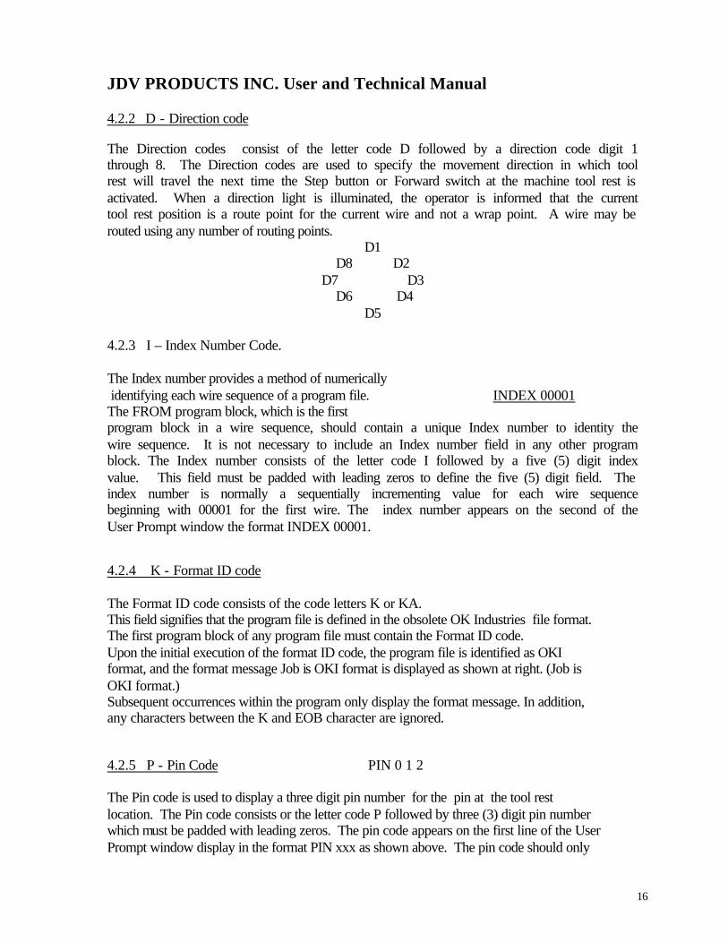
JDV PRODUCTS INC. User and Technical Manual 4.2.2 D - Direction code The Direction codes consist of the letter code D followed by a direction code digit 1 through 8. The Direction codes are used to specify the movement direction in which tool rest will travel the next time the Step button or Forward switch at the machine tool rest is activated. When a direction light is illuminated, the operator is informed that the current tool rest position is a route point for the current wire and not a wrap point. A wire may be routed using any number of routing points. D1 D8 D2 D7 D3 D6 D4 D5 4.2.3 I – Index Number Code. The Index number provides a method of numerically identifying each wire sequence of a program file. INDEX 00001 The FROM program block, which is the first program block in a wire sequence, should contain a unique Index number to identity the wire sequence. It is not necessary to include an Index number field in any other program block. The Index number consists of the letter code I followed by a five (5) digit index value. This field must be padded with leading zeros to define the five (5) digit field. The index number is normally a sequentially incrementing value for each wire sequence beginning with 00001 for the first wire. The index number appears on the second of the User Prompt window the format INDEX 00001. 4.2.4 K - Format ID code The Format ID code consists of the code letters K or KA. This field signifies that the program file is defined in the obsolete OK Industries file format. The first program block of any program file must contain the Format ID code. Upon the initial execution of the format ID code, the program file is identified as OKI format, and the format message Job is OKI format is displayed as shown at right. (Job is OKI format.) Subsequent occurrences within the program only display the format message. In addition, any characters between the K and EOB character are ignored. 4.2.5 P - Pin Code PIN 0 1 2 The Pin code is used to display a three digit pin number for the pin at the tool rest location. The Pin code consists or the letter code P followed by three (3) digit pin number which must be padded with leading zeros. The pin code appears on the first line of the User Prompt window display in the format PIN xxx as shown above. The pin code should only

17
JDV PRODUCTS INC. User and Technical Manual be used if the pin name can not be explicitly identified using a quote code (see section 4.2.6). 4.2.6 Q - Quote code The Quote code consists of the letter code Q followed by a prompt line digit, 1 through 3 followed by a character string which must be terminated by the comma (,) character. The Quote feature provides a method of displaying messages on the User Prompt display to direct the operator during the wire wrapping process. The prompt line digit following the Quote code letter specifies the line or lines at which the Quote message should appear. Line 1 selects the first display line, line 2 specifies the second display line and line 3 specifies both display lines. The Index number and bin number are displayed on the second FROM U01-1 line of the display during most program blocks which position INDEX 00001 the tool rest to a location on the panel. This leaves the first line BIN 001 of the display available for identifying the pin wrapped. In the example shown on the right, the program block identifies the wrap point with the Quote Q1FROM U01-1, which indicates a FROM wire wrap at the panel location UOl-l. Using the Quote code, the first display line may be programmed to identify a FROM block, a TO block, a VIA route block or any other program block that requires the identification of the tool rest position on the panel. In addition, the Quote code can be used to display messages CHANGE TO BIN 002 between wire sequences. The display can be used to display messages for bin changes, a level change, a zero check or any type or operation that the wire wrap operator should perform before wrapping any additional wires. 4.2.7 R - Rewind code Returning to start The rewind code consists of the letter code R. The Rewind code should be that final block of the program file. Upon execution of the Rewind code, the machine repositions to the start of the program file being used. Once this is done, the operator may un-mount the finished panel and, it required, mount the next panel of the same design to be wrapped. The machine is position at the first program block of the program file. 4.2.8.0 - T Codes The T code is used to specify various functions for the system. There are eight (8) T codes available and all are explained below.

18
JDV PRODUCTS INC. User and Technical Manual 4.2.8.1 T1 - From Code The From code is identified as T1 and indicates the first wrap FROM encountered in a program block, the message FROM appears at the beginning of the first display line as shown at right. The FROM code should only be used if the FROM wrap can not be explicitly identified using a Quote code (see section 4.2.6). 4.2.8.2 T2 - To Code The TO code is identified as T2 and indicates the second wrap TO point of a wire. When the.T2 code is encountered in a program block, the message TO appears at the beginning of the first display line as shown at right. The TO code should only be used if the TO wrap can not be explicitly identified using a Quote code (see section 4.2.6) 4.2.8.3 T3 - Via Lights Code The Via Lights code is identified as T3. When the T3 code is encountered in a program block all eight (8) via direction LEDs of the compass will light. 4.2.8.4 T4 - Zero Code The zero code is identified as T4. When the T4 code is encountered in a program block, the tool rest moves to the zero point. After completion of every 25th wire sequence, it is suggested to include a zero check program block to ensure that the machine zero has not been changed. 4.2.8.5 T5 - Alarm Codes The Alarm code is identified as T5. This code causes the machine to sound the audible alarm. The Alarm code can be used to gain the operators attention and prompt them to consult the display for instructions. 4.2.8.6 T6 - Trace Mode Code Trace mode not supported. 4.2.8.7 T7 - Auto Cycle on Code The Auto cycle on code is identified as T7. This code causes machine to automatically execute each program block without waiting for the operator to press the FWD key or Forward switch.

19
JDV PRODUCTS INC. User and Technical Manual A momentary pause of approximately one second will occur before each block to be executed. The Auto Cycle mode can be terminated by the Auto Cycle off code t8, or by mouse left click on the reset tool bar. 4.2.8.8 T8 - Auto Cycle Off Code The Auto cycle off code is identified as T8. The code causes the machine to end the Auto cycle mode if it has been previously set. The Auto cycle mode Can also be terminated by left clicking mouse on reset tool bar, pressing emergency stop or switching to a different operating mode. After termination of the Auto Cycle, work zero must be reset. 4.2.9 X - X coordinate Code The machine uses a Cartesian coordinate system (see section 4.1.2). The X Coordinate code positions the tool rest on the X axis to a position that is relative to the zero location. This field consists of the letter code X followed by a positive (+) or negative (-} sign followed by a five (5) digit value which must be padded with leading zeros. The tool rest will remain at the specified X coordinate location until superceded with another X Coordinate code. Therefore, it is not necessary to define the X coordinate if the tool rest is already at the required X location. The X and Y Coordinates must be specified in move units (1 unit = 0.0025 inches = 2.5 mils = .0635mm). 4.2.10 Y - Y Coordinate Code The Y Coordinate code positions the tool rest on the Y-axis to a position that is relative to the zero location. This field consists of the letter code Y followed by a positive (+) or negative (-) sign followed by a five (5) digit value which must be padded with leading zeros. The tool rest will remain at the specified Y coordinate location until superceded with another Y coordinate code. Therefore, it is not necessary to define the Y Coordinate if the tool rest is already at the required Y location. The x and y-coordinates must be specified in move units (1 unit = 0.0025 inches = 2.5 mils = 0,0635 mm).
20
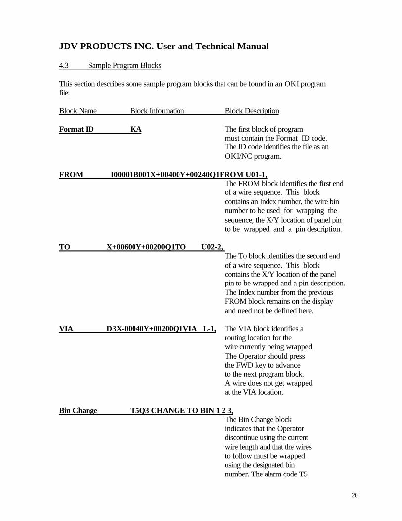
JDV PRODUCTS INC. User and Technical Manual 4.3 Sample Program Blocks This section describes some sample program blocks that can be found in an OKI program file: Block Name Block Information Block Description Format ID KA The first block of program
must contain the Format ID code. The ID code identifies the file as an OKI/NC program.
FROM I00001B001X+00400Y+00240Q1FROM U01-1,
The FROM block identifies the first end of a wire sequence. This block contains an Index number, the wire bin number to be used for wrapping the sequence, the X/Y location of panel pin to be wrapped and a pin description.
TO X+00600Y+00200Q1TO U02-2,
The To block identifies the second end of a wire sequence. This block contains the X/Y location of the panel pin to be wrapped and a pin description. The Index number from the previous FROM block remains on the display and need not be defined here.
VIA D3X-00040Y+00200Q1VIA L-1, The VIA block identifies a routing location for the wire currently being wrapped. The Operator should press the FWD key to advance to the next program block. A wire does not get wrapped at the VIA location. Bin Change T5Q3 CHANGE TO BIN 1 2 3, The Bin Change block indicates that the Operator discontinue using the current
wire length and that the wires to follow must be wrapped using the designated bin number. The alarm code T5

21
JDV PRODUCTS INC. User and Technical Manual Block Name Block Information Block Description alerts the Operator to look at display and change bin numbers. Level Change T4T5Q3 LEVEL CHANGE, The level change block indicates that the wires to follow must be wrapped at the next level. The alarm code T5, alerts the operator to look at the display and ascertain that there is a level change. Zero Check T4KA The zero check block, positions the tool at the zero location of the panel. This operation should be performed periodically
every 25 wires, to ensure the machine zero has not changed.
Rewind R The final block of any program should contain the Rewind code. This code returns back to the start of the program file. 4.4 Program organization Principles Program organization plays an important role in the quality of work produced by the wire wrap operator. The better the organization of the program data, the higher the quality of work the operator can produce. The operator can do only what the program instructs, and only in the sequence that occurs in the program. If the program is organized for an efficient wiring sequence, productivity will be maximized. If the program is random and inefficient, the productivity will be restricted which neither the machine nor the operator can overcome. This section describes the organization principles that should be followed for the production of efficient programs. To begin, all nets should be optimized for the shortest wiring path. The shortest wiring path means that the least amount of wire necessary to wrap the panel is being used, and therefore the lowest cost in wire. In addition, the shorter the interconnections the less likely there will be electrical problems in the panel due to factors such as wire buildup or noise.

22
JDV PRODUCTS INC. User and Technical Manual All wires should be assigned such that both ends of the wire are wrapped at the same level. This procedure aids in reworking. wires that are wrapped in a daisy chain method, where one end of a wire is wrapped at level 1 and the second end is wrapped at level 2, say require removal of the entire net in order to change a single wire. Wrapping both ends of the wire at the same level decreases the rework time required to make changes. The ordering of each wire requires great consideration for producing an efficient program. Efficiently sorting the wires by level, bin and panel location will greatly increase the productivity of the operator. There are three main types of wire sorting that must be performed. 1. Sorting each wire by level. The operator should completely wrap all level 1 wires
before wrapping the level 2 wires. 2. Sort each wire by bin number. The main advantage at sorting by wire length is that
the operator does not need to read the wire bin number from the display and reach for a new wire for each wire sequence. Rather, the program should be coded with an audible alarm and a bin change message to announce a wire bin change. Only at this time does the operator have to examine the bin display and take a hand-full of wires for the new bin. The least amount of work for the operator means less fatigue, less error and higher productivity.
3. Sort each wire by location. The less the tool rest moves, the less that the operator
has to move and the less the operator becomes fatigued from the work. A final, but equally important, consideration for the wiring program is that each wire must be programmed so that the left-most pin of the wire sequence is wrapped first. This prevents the tool rest from covering the FROM pin once it has been wrapped. If the two pins to be wrapped are located on the same X coordinate, then the top-most pin must be wrapped first (see section 4.1.4)
23
JDV PRODUCTS INC. User and Technical Manu
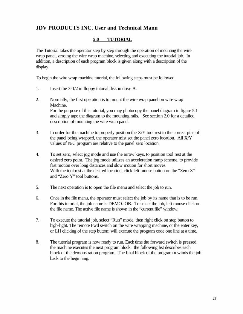
5.0 TUTORIAL The Tutorial takes the operator step by step through the operation of mounting the wire wrap panel, zeroing the wire wrap machine, selecting and executing the tutorial job. In addition, a description of each program block is given along with a description of the display. To begin the wire wrap machine tutorial, the following steps must be followed. 1. Insert the 3-1/2 in floppy tutorial disk in drive A. 2. Normally, the first operation is to mount the wire wrap panel on wire wrap Machine.
For the purpose of this tutorial, you may photocopy the panel diagram in figure 5.1 and simply tape the diagram to the mounting rails. See section 2.0 for a detailed description of mounting the wire wrap panel.
3. In order for the machine to properly position the X/Y tool rest to the correct pins of
the panel being wrapped, the operator mist set the panel zero location. All X/Y values of N/C program are relative to the panel zero location.
4. To set zero, select jog mode and use the arrow keys, to position tool rest at the
desired zero point. The jog mode utilizes an acceleration ramp scheme, to provide fast motion over long distances and slow motion for short moves. With the tool rest at the desired location, click left mouse button on the “Zero X” and “Zero Y” tool buttons.
5. The next operation is to open the file menu and select the job to run. 6. Once in the file menu, the operator must select the job by its name that is to be run.
For this tutorial, the job name is DEMO.JOB. To select the job, left mouse click on the file name. The active file name is shown in the “current file” window.
7. To execute the tutorial job, select “Run” mode, then right click on step button to
high-light. The remote Fwd switch on the wire wrapping machine, or the enter key, or LH clicking of the step button; will execute the program code one line at a time.
8. The tutorial program is now ready to run. Each time the forward switch is pressed,
the machine executes the next program block. the following list describes each block of the demonstration program. The final block of the program rewinds the job back to the beginning.

24
JDV PRODUCTS INC. User and Technical Manual N/C program Blocks Description Display __________________________________________________________________________ KA N/C Job is OKI format The format ID code KA specifies the OKI N/C data format. INDEX I00001B001X-00120Y-00040Q1FROM 2-2 FROM 2-2 The index code I00001 specifies the wire index INDEX 00001 number. The Bin code B001 specifies the BIN 001 wire bin to be used. The X-00120 and
Y-00040 codes specify the position of the FROM Pin to be wrapped. The quote message Q1 FROM 2-2 specifies the pin ID at the FROM X/Y location. X+00000Y-00040Q1TO 1-2, TO 1-2 The X+00000 and Y-00040 codes specify the position of the TO pin to be wrapped. The Quote message Q1 1-2, specifies the pin ID at the TO X/Y location. T5Q3 CHANGE TO BIN 007, CHANGE TO The Audible Alarm code T5 sounds the alarm.
The BIN 007 Quote message Q3 CHANGE TO BIN 007 informs the operator that the wire bin is required
for the wires to follow. I00002B007X-00240Y-00480Q1FROM 3-13, FROM 3-13 The index code I00002 specifies the wire index INDEX 00002 number. The bin code B007 specifies the wire bin BIN 007 to be used. The X-00240 and Y-00480 codes specify the position from the pin to be wrapped. The quote message Q1 FROM 3-13 specifies the ID at the FROM X/Y location. D2X-00120Y-00480Q1VIA 2-13, VIA 2-13 A Via sequence specifies a routing point as opposed to a wrapping point. The Direction code D2 specifies that

25
JDV PRODUCTS INC. User and Technical Manual N/C Program Blocks Description Display __________________________________________________________________________
the next tool rest movement will be northeast. The X and Y codes specify the panel location of this via point and the quote message Q1VIA 2-13, specifies the pin ID of the Via point.
X-00000Y-00080Q1TO 1-3, The X and Y codes specify the panel location of the TO pin to be wrapped. The Quote message
Q1 TO 1-3 specifies The pin ID at the TO X/Y location.
T4T5Q1 CHANGE TO BIN 009, Q2 LEVEL CHANGE, CHANGE TO The program block is typical for a wrapping level BIN 009 change. The code T4 returns the tool rest to the LEVEL CHANGE zero location.
The code T5 sounds the audible alarm. The Quote message Q1 CHANGE TO BIN 009, specifies a bin change and the Quote message Q2 LEVEL CHANGE, specifies the change in wrapping level.
I00003B009X-00840Y-00440Q1FROM 8-12, FROM 8-12 The Index code I00003 specifies the wire index INDEX 00003 The Bin code B009 specifies the wire bin to be used. BIN 009 The X and Y codes specify the location of the FROM pin to be wrapped. The Quote message
Q1FROM 8-12, specifies the pin ID at the FROM X/Y location.
X-00120Y-00040Q1TO 2-2, TO 2-2 The X and Y codes specify the panel location of the
TO pin to be wrapped. The Quote message Q1 2-2 specifies the pin ID at the TO X/Y location.

26
JDV PRODUCTS INC. User and Technical Manual N/C Program Blocks Description Display __________________________________________________________________________ R Returning to start The Rewind Code R specifies the end of the job
program. It will sound the audible alarm and repositon itself back to the beginning of the
program file.
6.0 SERVICE ITEMS 6.0.1 LUBRICATION: The SW tables are equipped with self-lubricating bushings and lead nuts. 6.0.2 GENERAL MAINTENANCE: In general, keeping the machine clean is the only maintenance requirement for the wrapping table. Scrap Kynar insulation from stripped wires will some times adhere to moving parts and can interfere with proper operation of the equipment. Vacuuming and/or wiping down after each shift is recommended. There are four shafts used to guide the guard belt. These will gum-up in use and require cleaning. Use a –Q- tip dipped in denatured alcohol to clean once every 3 months.
7.0. SPARE PARTS LIST QTY DESCRIPTION PART NUMBER _____________________________________________________________________ 2 NYLAD BEARING A-12522 1 STEPPER MOTOR (SWT 2100 ONLY) A-12407 1 STEPPER MOTOR (SWT 1100 AND SWT 2100) A-12469 1 EMERGENCY SWITCH A-12524 1 REMOTE FWD SWITCH A-12417 1 FUSE 2A A-10060 2 FUSE 4A A-11700

27
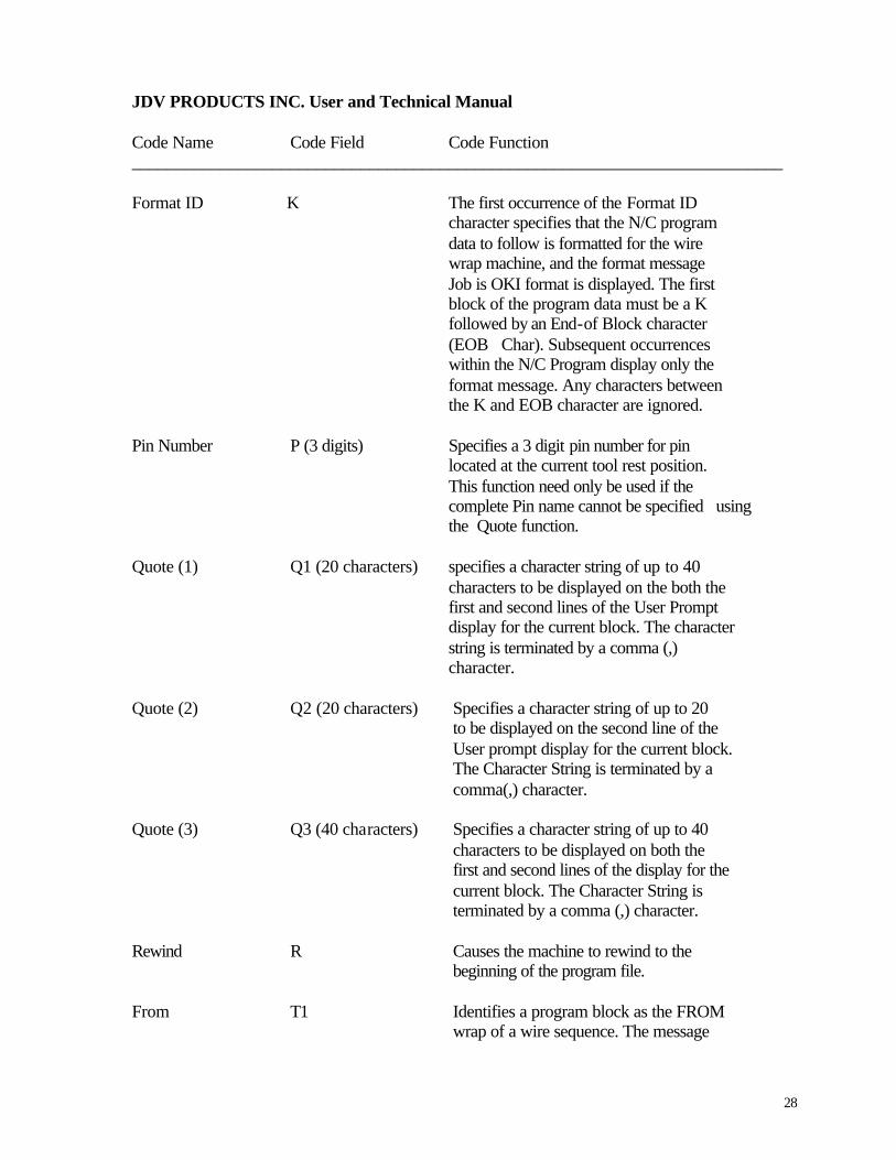
JDV PRODUCTS INC. User and Technical Manual PROGRAM CODE SUMMARY Code Name Code Field Code Function __________________________________________________________________________ Bin Number B (3 digits) Specifies the wire bin number for the current program block. The Bin Number appears on the second line of the display as Bin xxx N-Direction D1 Lights the north direction LED of the compass for the current program block. NE-Direction D2 Lights the north east direction LED of the compass for the current program block. E-Direction D3 Lights the east direction LED of the compass For the current program block. SE-Direction D4 Lights the south east direction LED of the compass for the current program block. S-Direction D5 Lights the south direction LED of the compass for the current program block. SW-Direction D6 Lights the south west direction LED of the compass for the current program block. W-Direction D7 Lights the west direction LED of the compass for the current program block. NW-Direction D8 Lights the north west direction LED of the compass for the current program block. Index Number I (5 digits) Specifies the machine index number which will remain in effect until superceded. the Index Number appears on the second line of the display as INDEX xxx.
28
JDV PRODUCTS INC. User and Technical Manual Code Name Code Field Code Function __________________________________________________________________________ Format ID K The first occurrence of the Format ID character specifies that the N/C program data to follow is formatted for the wire wrap machine, and the format message
Job is OKI format is displayed. The first block of the program data must be a K followed by an End-of Block character
(EOB Char). Subsequent occurrences within the N/C Program display only the format message. Any characters between the K and EOB character are ignored. Pin Number P (3 digits) Specifies a 3 digit pin number for pin located at the current tool rest position.
This function need only be used if the complete Pin name cannot be specified using the Quote function.
Quote (1) Q1 (20 characters) specifies a character string of up to 40 characters to be displayed on the both the first and second lines of the User Prompt display for the current block. The character string is terminated by a comma (,) character. Quote (2) Q2 (20 characters) Specifies a character string of up to 20 to be displayed on the second line of the User prompt display for the current block. The Character String is terminated by a comma(,) character. Quote (3) Q3 (40 characters) Specifies a character string of up to 40 characters to be displayed on both the first and second lines of the display for the current block. The Character String is terminated by a comma (,) character. Rewind R Causes the machine to rewind to the beginning of the program file. From T1 Identifies a program block as the FROM
wrap of a wire sequence. The message

29
JDV PRODUCTS INC. User and Technical Manual Code Name Code Field Code Function __________________________________________________________________________
FROM appears on the second line of
the display (unless the T1 code is followed by a Q code in the current program block.) To T2 Identifies a program block as the TO wrap of a wire sequence. The message TO appear on the second line of the display (unless the T1 code is followed by a C code in the current program block). Via Lights T3 Lights all 8 direction LEDs of the compass for the current program block. Zero T4 Returns the X/Y tool rest to the 0/0 location. Alarm T5 Sounds the audible alarm for the current program block. Trace T6 Not supported. Auto Cycle On T7 Causes the SW to automatically execute each program block without waiting for operator to press the FWD button. Auto Cycle Off T8 Causes the SW to end the Auto Cycle mode if it has previously been set. The Auto Cycle mode can also be terminated by pressing the reset button. X Coordinate X (±5 digits) Positions the machine tool rest in the X-axis to a position relative to the machine 0/0 point. The tool rest will remain at the specified location until superceded with another X code. The X and Y coordinates are specified in machine units (1 machine unit = 2.5 mils). Y Coordinate Y (±5 digits) Positions the machine tool rest in the Y-axis to a position relative to the machine 0/0 point. The tool rest will remain at the specified Location until superceded with another Y code. The X and Y coordinates are specified in machine units (1 machine unit = 2.5 mils).

30
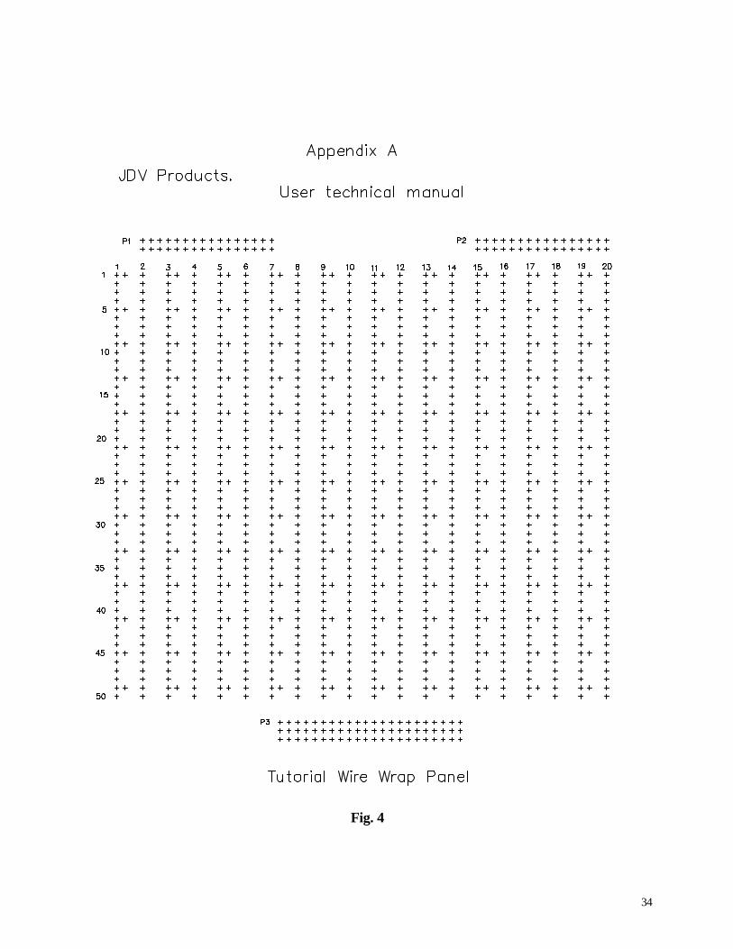
JDV PRODUCTS INC. User and Technical Manual End-of-Block (EOB char) Causes the machine to execute the program codes specified in the program block read. For ASCII data, the (EOB char) is and ASCII Carriage Return. For EIA data, it is the EIA EOB character. NOTES Text appearing in brackets in the Code Field describes the data which must be specified for the code. For example, the Index Number is defined as I (5 digits) which is the character “I” followed by 5 digits. X (+-5 digits) is the character “X” followed by either a plus (+) or minus (-) sign, followed by 5 digits. B) A program block consists of all codes located between two EOBs. Appendix A Fig. 1 Suggested component arrangement. Fig. 2 -Y- carriage reassembly SWT 2000 and SWT 3000 series. Fig. 3 Computer interfaces. Fig. 4 Tutorial wire wrap panel.

31
Fig. 1 Suggested Component Arrangement

32
Fig. 2 Y- Carriage Reassembly
SWT 2000 And SWT 3000 Series

33
Fig. 3 Computer Interfaces
34
Fig. 4