use of ultra-high performance concrete in bridge design · use of ultra-high performance concrete...
TRANSCRIPT
Use of Ultra-High Performance Concrete in Bridge Design
Sri Sritharan1, Sriram Aaleti2, Jessica Garder3, Dean Bierwagen4, Ahmad Abu-Hawash5
Abstract
With an intention of increasing lifespan of bridges, several initiatives to use Ultra-High Performance Concrete (UHPC) have been undertaken in the State of Iowa. This paper summarizes three such ongoing initiatives. In the first initiative, a prefabricated UHPC waffle deck panel was developed. Following investigation of the constructability and performance of critical connections and panels through large-scale testing, a field structure with waffle decks has been completed. The second initiative explores a cost-effective, composite deck system using UHPC and normal concrete (NC), which led to a suitable interface for the composite deck. For the previously developed tapered H-shaped UHPC pile, the third initiative established splice and pile-to-abutment connections to assist with field implementation of this pile.
Introduction
The United States bridge infrastructure has received a ‛C’ grade by the American Society of Civil Engineers (ASCE), which is primarily due to the structural deficiency or functional obsoleteness of one in four of the nation’s bridges (ASCE, 2009). At the end of 2008, the estimated total number of bridges in the nation was 600,905, of which 72,868 (12.1%) were identified as structurally deficient, while 89,024 (14.8%) were listed as functionally obsolete. Unfortunately more bridges are added to this list annually, especially those from urban areas, where it is considered that one in every three bridges is deficient (ASCE, 2009). To overcome the nation’s aging bridge infrastructure, several State Departments of Transportation (DOTs) and the Federal Highway Administration (FHWA) have engaged in the development of: a) durable, broadly applicable bridge components and systems that are cost-effective; and b) accelerated bridge construction methods to rapidly resolve the bridge deterioration problem of the nation. Due to its superior structural and durability characteristics, the use of Ultra-High Performance Concrete (UHPC) for bridge applications has gained momentum in the United States over the past decade.
Through collaboration between Iowa DOT, FHWA, Iowa State University (ISU), 1 Wilson Engineering Professor, Department of Civil, Construction and
Environmental Engineering, Iowa State University, Ames, Iowa 2 Research Assistant Professor, Department of Civil and Environmental Engineering,
Iowa State University, Ames, Iowa 3 Structural Engineer, Burns & McDonnell, Kansas City, Missouri 4 Final Design Section Leader, Iowa Department of Transportation, Ames, Iowa 5 Chief Structural Engineer, Iowa Department of Transportation, Ames, Iowa

Lafarge and Coreslab Structures (OMAHA), the State of Iowa has led the nation in utilizing UHPC for bridge substructure and superstructure. The past applications include: design, testing and deployment of I-shaped girders; π-shaped girders; and design of a tapered, H-shaped precast pile. There are three ongoing UHPC projects that are in near completion stage (Sritharan et al. 2012). The first two projects focus on using UHPC for bridge decks and the third on Phase 2 of the pile foundation program. Each of these initiatives, summarized below, is aimed at producing durable and longer-lasting critical bridge components that can be easily deployed.
UHPC Waffle Deck Panel
By combining the advantages of UHPC and prefabricated full-depth deck systems, a precast UHPC waffle deck system was developed as part of FHWA’s Highways for LIFE program. The constructability of this system and structural performance of its critical connections and panels were investigated using large-scale laboratory tests, which applied service, fatigue, and ultimate loads (Aaleti et al., 2010). Subsequently, a UHPC precast waffle deck system with mild steel reinforcement was developed for replacement of a two-lane, single-span bridge in Wapello County, Iowa. This bridge, which is 10.1-m wide and 18.3-m long, was designed and built with five standard Iowa “B” girders, at a center-to-center distance of 2.2 m (see Figure 1).
FIGURE 1: CROSS-SECTION OF THE UHPC WAFFLE DECK BRIDGE
Details of Connections
To make the UHPC waffle deck panels fully composite with the girders, three types of connections were used, namely: 1) a pocket connection; 2) a longitudinal connection, and 3) a transverse connection. The pocket connection consisted of at least one shear hook extending from the top of the girder into a pocket in the waffle deck panel, which was filled with in-situ UHPC (see Figure 2a). This detail established the connection between the waffle deck panel and exterior or intermediate girders (see detail B in Figure 1). The longitudinal connection was used between the waffle panels and center girders. Dowel bars extending from the panels with shear hooks from the girders (as with detail B), and additional longitudinal mild steel reinforcement was used with in-situ UHPC (see Figure 2b) for this connection. The transverse connection joined two
10.1 m bridge width
4 spaces at 2.24 m
0.58
m
51 m
m
203
mm
63.5
mm

adjacent UHPC waffle deck panels utilizing dowel bars extended from the panels, two additional transverse reinforcement, and in-situ UHPC (see Figure 2c).
FIGURE 2: DETAILS OF CONNECTIONS USED FOR UHPC WAFFLE DECK BRIDGE
Full-scale Testing
Two full-scale, full-depth, UHPC waffle deck panels connected to two precast, prestressed girders were tested to evaluate the structural characterizations of the panels and connections. In addition to subjecting a panel and connections to AASHTO (2007) specified service and fatigue wheel loads, overload and ultimate load tests were also performed. The experimental investigation was complemented with a detailed finite element analysis (FEA) by assuming perfect bonding between precast panels, in-situ UHPC, and reinforcement. Figure 3 shows the construction of joints and test setup.
FIGURE 3: CONSTRUCTION OF JOINTS AND TEST SETUP
Field Installation
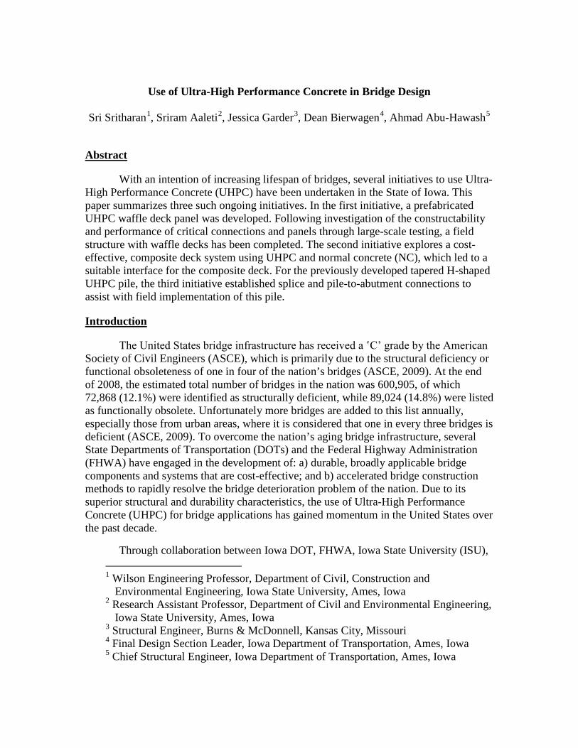
Following successful design and performance verification, the waffle deck bridge system was completed in Wapello County, Iowa (see Figure 4). Following placement of the girders, the waffle decks were put in place with ease and the construction of all UHPC joints was completed without any difficulties. The field installation of the waffle deck was completed as planned. With no prior experience, the contractor was able to
place the deck panels without encountering any difficulties and grouted the joints with UHPC mixed onsite. The mixing of the UHPC was handled by an experienced personal.
(a) Placing of waffle deck panels (b) Completed bridge
FIGURE 4: WAFFLE DECK BRIDGE IN IOWA
Key Findings
As shown in Table 1, a total of eight tests were conducted in this sequence to critically evaluate the performance of the waffle panels and connections (Aaleti et al., 2011a). Each test produced satisfactory performance. Under service level loading, only limited micro cracking was observed on the most critical rib and the transverse joint during the panel and joint testing, respectively. When the test was repeated for more than a million cycles for fatigue load assessment, no progressive degradation of the system was observed. When a panel and the joints were overloaded, visible flexural cracks were noted on the transverse and longitudinal ribs. To examine the ultimate strength, a panel and the joints were subjected to three to four times the service level wheel loads. Significant cracking to the ribs was observed, but no failure of the connection or the panels occurred. However, the test was terminated at this stage due to significant cracking that occurred to the bridge girders supporting the panels. The FEA accurately predicted the load and location of the first flexural crack and the regions susceptible to increased cracking as a result of an increase in load (Aaleti et al., 2011b). A successful installation of the waffle deck in the field confirmed that this new deck system can be efficiently deployed in the field.
UHPC-NC Composite Deck
Following the success of the UHPC waffle deck concept, the development of an innovative composite deck system using UHPC overlying normal concrete (NC) was undertaken. The ultimate goal of this project is to come up with a cost-effective UHPC-NC bridge deck system that can be used for new and existing bridge decks as a means for increasing lifespan of the superstructure. The study has focused on structural

characterization of different shear friction interfaces that may be appropriate for overlying UHPC on NC slabs, as well as load testing of small segments of bridge decks.
TABLE 1: SUMMARY OF TESTS CONDUCTED ON THE WAFFLE DECK SYSTEM
Test ID Description Load (kN) Expected Damage from FEA
1 Service load at center of a panel 95 Micro cracking in ribs
2 Service load on transverse joint 125 Micro cracking in joint
3 Fatigue test on transverse joint
125 x 1 million cycles No prediction was made
4 Overload on transverse joint 214 Visible flexural cracks along the joint and transverse ribs
5 Fatigue test of panel 95 x 1 million cycles No prediction was made
6 Overload on panel 178 Visible flexural cracks along transverse ribs
7 Ultimate load on panel 712 Significant flexural cracks along transverse and longitudinal ribs
8 Ultimate load on transverse joint 689 Significant flexural cracks along
transverse and longitudinal ribs Shear Friction Tests
As summarized in Table 2, a test matrix that consisted of five different textures and three concrete strengths was used to examine the feasibility and effects of different interface textures, concrete strength, casting sequence, and curing condition (fully cured vs. partially cured vs. wet conditions) on the shear friction behavior of the composite deck interface. Mechanical connections between UHPC and NC such as that involving shear studs were disregarded to ensure easily constructible details.
Based on the experimental study on the bond behavior of composite specimens incorporating UHPC (Harris et al., 2010) and the slant shear test concept (Wall and Shrive, 1988), all interface tests were completed using prismatic members as shown in Figure 5a. Each UHPC-NC composite specimen was 150 mm by 150 mm in cross-section, 600 mm long, and consisted of an inclined joint with different interface textures at the mid-height of the specimen. An inclination angle of 53.1 degrees was chosen for the interface based on the preliminary calculations and previous research (Zilch and Reinecke, 2000). The joint interface surface was prepared using five different form-liners with varying roughness values that typically used in the precast industry for architectural panels. As the specimens were subjected to uniaxial compression at the ends, the interface was subjected to shear stresses along the inclined joint interface. Several instruments, including displacement transducers and rotation meters, were used in the

joint region to adequately characterize the performance, and closely monitor the movement along the inclined shear interface. All samples were tested to failure at the interface or through splitting of the NC (see Figure 5a).
TABLE 2 SUMMARY OF COMPLETED UHPC-NC INTERFACE TESTS
Test type Texture (# of specimens) Casting sequence Target NC
Strength
UHPCw-NC5 5 textures (3 per texture)
Wet UHPC over Cured NC 34 MPa
UHPCw-NC7 5 textures (3 per texture)
Wet UHPC over Cured NC 52 MPa
UHPCw-NC10 5 textures (3 per texture)
Wet UHPC over Cured NC 69 MPa
UHPCh-NC5 5 textures (3 per texture)
Wet NC on Heat treated UHPC 34 MPa
w –wet UHPC; h-heat treated UHPC
a) Compression failure of a test specimen
b) Average bond strength for different surface textures
FIGURE 5: CROSS-SECTION OF THE UHPC WAFFLE DECK SYSTEM BRIDGE
Testing of UHPC-NC Composite Decks
Following the investigation on the interface test units, three UHPC-NC composite deck specimens with a texture depth varying from 2 mm to 6 mm were tested under combined flexural and shear loading. The test configuration used a three-point bending setup shown in Figure 6a. In each case, the dimensions of the NC portion were 2.74 m (length) x 0.81 m (width) x 203 (thickness), which represented a portion of the standard Iowa DOT bridge deck. All the specimens were constructed using 28 MPa concrete. Consistent with the Iowa DOT standards, a 38-mm thick UHPC overlay was placed after the normal concrete was cured. The measured force-displacement responses of the three
UHPC
NC

specimens are shown in Figure 6b. At the service level loading of 95 kN, a few hairline cracks formed directly under the load. All specimens ultimately failed with the initiation of shear failure in the normal concrete portion of the composite deck at a load in the range of 320 to 347 kN, which is nearly 4.5 - 4.9 times the design wheel load. The slip along the UHPC-NC interface was monitored, but no slip at the interface was observed until the initiation of the shear failure in the specimens. The damaged state of two specimens is shown in Figure 6c.
Key Findings
A total of 60 slant UHPC and NC interface specimens were tested. The average depth of texture was varied from 5 mm to 1.3 mm from texture 1 to texture 5. In each case, the stress along the interface and bond strength was calculated by dividing the appropriate load along the joint by the interface area. A comparison of the average bond capacity established under shear for each surface is presented in Figure 5b. Accordingly, it was found that the bond strength developed for all textures was adequate for applications in bridge decks. The bond strength generally increased with the increase of texture roughness. The casting sequence, however, did not significantly influence the bond strength. The tested deck specimens revealed that all three interfaces would be adequate for composite action. The broom finish specimen did not experience any significant ductility once the capacity was reached due to delamination of the overlay. In the other two specimens, large shear deformations and yielding of the reinforcement occurred, contributing to strain hardening until delamination occurred, which appeared to be triggered by shear failure.
FIGURE 6: INVESTIGATION OF UHPC-NC COMPOSITE DECK (1 in = 25.4 mm)
Connections and Field Tests of UHPC piles
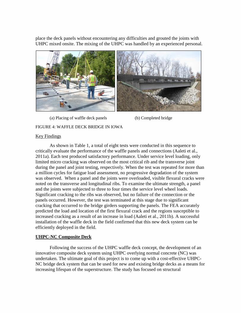
For routine bridges, the foundation can contribute up to 30% of the overall bridge cost. Furthermore, increasing the longevity of bridges requires an increase in the durability of the foundation as well. Consequently, a tapered, H-shaped, UHPC pile was previously developed at ISU as a means for increasing the longevity of bridge foundations and reducing the maintenance cost in comparison to steel and concrete piles (Vander Voort et al., 2008). The cross-section details of this pile and a steel H-pile that is more commonly used in Iowa are compared in Figure 7.
(a) Cross section detail (1 in. – 25.4 mm) b) Steel vs. UHPC pile properties
FIGURE 7: COMPARISON OF UHPC AND HP 250 X 85 PILE SECTIONS
The full-scale vertical and lateral load tests on UHPC piles revealed several benefits of the UHPC pile including reduced risk of damage during driving, drivability with a greater range of hammers and strokes, and use of the existing equipment for pile handling and driving. To implement the UHPC piles in bridge foundations, it was necessary to develop suitable connection details to splice piles in the field while ensuring the UHPC piles will be adequately anchored into the pile caps and bridge abutments.
Splice Details
With the intention of minimizing construction delays, dry connections, comprising of welding, bolting or quick-set grout, are typically preferred to extend the piles in the field during driving. It is common practice to use welding when steel piles are spliced as this is considered an efficient technique in the field. Consequently, a welded detail was preferred for the splice of the UHPC piles. Figure 8 shows the steel embedment used at the ends of UHPC piles, which facilitates welding between two H-shaped steel plates to establish the connection. This splice was designed to have a minimum of 50% of the pile capacity in tension and 100% of the pile moment capacity.
Pile-to-Abutment Connections
The connection of the UHPC pile-to-abutment was established using the typical Iowa DOT standard details that are routinely used for steel pile-to-abutment connection

(Iowa DOT, 2011). This approach was preferred in order to minimize changes to an already established construction practice due to the change in pile material.
Laboratory Testing
Full-scale laboratory tests were completed to verify the expected behavior and to ensure adequate capacity of the UHPC splice connections. The laboratory investigation included the testing of the splice region under direct tension, as well as, critical shear and flexural stresses. Two test units were used for these tests. In each case, two 1.22-m long UHPC pile segments were cast and spliced together at the ends using an 8 mm weld all around the interface at the splice. As shown in Figure 9a, the direct tension test was performed on the test unit using a self-reacting test frame supported on rollers, while the shear and flexural tests were performed using a simply supported configuration and a concentrated vertical load, as shown in Figure 9b.
FIGURE 8: STEEL EMBEDMENT USED FOR SPLICING UHPC PILES (1 in = 25.4 mm)
FIGURE 9: UHPC SPLICE TESTS (1 in. = 25.4 mm; 1 kip = 4.448 kN)

The pile-to-abutment connection test was performed on a steel pile and a UHPC pile in an inverted position under combined axial and lateral loads as shown in Figure 10a. For each test, a 2.4-m long pile segment was embedded into a cast-in-place concrete block, which had standard dimensions of a bridge abutment with its length equal to typical center-to-center distance between two adjacent piles. The abutment block was suspended above the floor by post-tensioning two concrete blocks on both sides and attaching these ancillary blocks to the strong floor using high strength bars. Throughout testing, the piles were subjected to either 445 kN or 890 kN of vertical load using two post-tensioning bars and hydraulic jacks. In addition, each pile was subjected to cyclic lateral displacements using a 450 kN actuator attached at a height of 1.4 m from the top of the abutment block, to simulate the expected movement of a pile integrally connected to abutments. Based on the previous studies on the thermal movements and subsequent expansion and contraction that integral abutment bridges undergo, the piles are expected to move as much as 25 mm in the longitudinal direction, which corresponds to a 5 mm lateral displacement for the short segment of the test pile in the laboratory. The UHPC pile was tested in three phases to understand the influence of vertical load on the behavior of the pile-to-abutment connection. The load protocol used for the three phases is shown in Table 3. In a similar manner, an HP 250 x 85 steel pile was also tested to failure to provide the baseline performance of the connection.
FIGURE 10: UHPC PILE-TO-ABUTMENT CONNECTION TEST
Key Findings
The full-scale tests on splice connection confirmed its satisfactory performance and indicated that the splice had reserve capacity in excess of 975 kN and 200 kN in tension

and shear, respectively. One concern identified during the tests was that the weld quality should be assured in order for the splice to perform as quantified from the tests. The UHPC pile-to-abutment connection was also very successful. The force-displacement responses of the UHPC and steel piles are shown in Figure 11. No cracking was observed in the UHPC pile at the expected level of lateral displacement of 5 mm. At 8 mm of lateral displacement, two hairline cracks were seen in the UHPC pile near the connection. However, these cracks were completely closed after the displacement of the pile returned to zero. The UHPC pile failed in compression at 38 mm lateral displacement. The steel pile experienced yielding in the flange tips at 13 mm of lateral displacement and buckling of flanges in the critical moment region at 102 mm of lateral displacement.
TABLE 3: LABORATORY PILE-TO-ABUTMENT TESTING PROTOCOL
Axial Load
(kN) # Cycles per
Step Control Load Step
Phase I 445 2 Force (kN) ±18, ±36, ±54, ±72
Phase II 890 2 Force (kN) ± 16, ±32, ±48, ±63
Phase III 445 3 Displacement (mm) ±13, ±19, ±25, ±38
(for steel: ±51, ±76, ±102)
FIGURE 11: CYCLIC LATERAL LOAD RESPONSE OF PILES
Field Testing
Two full-scale UHPC piles (i.e., P3 and P4) were tested in the field with the first one under vertical load and the second one using lateral load. The vertical load test used the

setup shown in Figure 12a, and followed "Procedure A: Quick Test" as outlined in ASTM D 1143/D 1143 M – 07 (ASTM, 2007a). Accordingly, the test pile was loaded in five percent increments up to the failure load. The load was kept relatively constant during each load step until deflection readings had stabilized. This test was performed to verify the vertical load capacity of a production pile with a design nominal capacity of 890 kN. The lateral load test used the setup shown in Figure 12b and the load was applied to P4 with respect to P3. In this setup, P3 was subjected to flexure about the weak axis while P4 was subjected to flexure about the strong axis. Furthermore, P4 used a splice at 4.5 m from the pile head (i.e., 3.6 m from the ground surface). The lateral load test was completed following "Procedure A: Standard Loading" of ASTM 3966-07(ASTM, 2007b). This procedure recommends applying a design load of 200% of the proposed pile lateral design load unless failure occurs first. A design lateral load of 45 kN was used for the test with a maximum lateral load of 92 kN.
FIGURE 12: SETUPS USED FOR UHPC PILE TESTS IN THE FIELD
Key Findings
Measured force displacement responses of piles are shown in Figure 13. Using the Davisson failure criterion as illustrated in Figure 13a (Davisson, 1976), the vertical UHPC pile capacity was determined to be 1321 kN, which was about 50% higher than designed nominal pile capacity. Figure 13b shows the lateral force-displacement curve for P4. The maximum measured load was 92 KN and the maximum lateral displacement was 254 mm. The splice in P4 performed well during installation and testing. No visible damage from driving or the lateral load test was found on or near the splice after excavation. The splice was subjected to compressive stresses of 39 MPa and a tensile stress of 0.7 MPa during driving. Based on the field measurements, the splice was subjected to 11.6 kN of shear, 5.9 kN-m of bending moment, and 2.5 mm of lateral displacement. The combination of results from the laboratory tests, in which the splice was subjected to significantly high shear and bending actions, and the field lateral load test proved that the splice attachment designed for the UHPC pile is robust and that it can be used in the field to splice UHPC piles efficiently.

FIGURE 13: MEASURED FORCE-DISPALCMENT RESPONSES FROM FIELD TESTS
Conclusions
Following successful use of UHPC in bridge research projects, three research initiatives were undertaken in Iowa with support from the state, FHWA and other agencies. Through these initiatives, it has been shown that 1) the UHPC waffle panel is a durable and easily constructible, full-depth precast option for bridge decks; 2) adequate shear resistance can be established between a UHPC and NC interface with minimum roughness of 2 mm at the interface and that UHPC can be used as a durable overlay in bridge decks; and 3) tapered H-shape piles can be spliced and connected to the pile caps and abutments as routinely done for steel H piles and that UHPC piles have significantly high axial load capacity than estimated from current design practice.
Acknowledgements
The authors would like to thank FHWA, Coreslab Structures of Omaha, Iowa DOT and Iowa Highway Research Board for sponsoring the research presented summarized in this paper. In addition, the authors are indebted to Vic Perry, Peter Seibert, and Kyle Nachuk of Lafarge North America for providing supports and assistance with mixing and casting of UHPC members, and Todd Culp and John Heimann from the Coreslab Structures of Omaha for prefabricating all of the UHPC members used in the three projects.
References
[1] Aaleti, S., Sritharan, S., Rouse, M., Wipf, T.: Phase1: The structural characterization of UHPC waffle bridge deck panels and connections. IHRB Project TR-614 Report, Iowa Department of Transportation, 2010.
[2] Aaleti, S., Sritharan, S., Bierwagen, D., and Terry J. Wipf (2011), “ Structural Behavior of Waffle Bridge Deck Panels and Connections of Precast Ultra-High-

Performance Concrete: Experimental Evaluation”, Transportation Research Record: Journal of the Transportation Research Board, No. 2251, Transportation Research Board of the National Academies, Washington, D.C., 2011, pp. 82–92.
[3] Aaleti, S., Sritharan, S., Dean Bierwagen and Brian Moore (2011) Precast UHPC Waffle Bridge Deck Panels and Connections for Accelerated Bridge Construction. PCI National Bridge Conference, Salt Lake City, Utah, 2011.
[4] AASHTO LRFD Bridge Design Specifications. American Association of State Highway and Transportation Officials, Washington, D.C., 2007
[5] American Society of Civil Engineers (ASCE): Report Card for America’s Infrastructure: Facts about bridges, Reston, VA, USA, 2009.
[6] ASTM. “Standard Test methods for Deep Foundations under Static Axial Compressive Load,” ASTM D1143/1143M-07, ASTM Standards, 2007.
[7] ASTM. “Standard Test Methods for Deep Foundations under Lateral Loads,” ASTM D3966-07, ASTM Standards, 2007.
[8] Davisson, M.T. “High Capacity Piles,” Proceedings, Lecture Series, Innovations in Foundation Construction, ASCE, Illinois Section, 1972.
[9] Harris, K., D., Sarkar, J., and Ahlborn, T.: Interface Bond Characterization of Ultra-High Performance Concrete Overlays. 90th Annual TRB Meeting, Washington D.C, January 2011.
[10] Iowa DOT, http://www.iowadot.gov/bridge/standards/english/EnglishIntegral Bridges.pdf, cited on 31 October 2011.
[11] Sritharan, S., Aaleti, S., Bierwagen, D., Garder, J., and Abu-Hawash, A. “Current Research on Ultra High performance Concrete for Bridge Applications in Iowa. Proceedings of the 3rd International Symposium on UHPC and Nanotechnology for High Performance Construction Materials, Kessel, Germany, 2012.
[12] Vande Voort, T., Suleiman, M. T., and Sritharan, S.: Design and performance verification of ultra-high performance concrete piles for deep foundations. Final Report, Iowa DOT, IHRB Project TR-558, CTRE Project 06-264, Iowa Dept. of Transportation, Ames, IA, 2008.
[13] Wall, J.S. and N.G. Shrive, Factors Affecting Bond Between New And Old Concrete. ACI Materials Journal,: p. 117-125, 1988.
[14] Zilch, K.; Reinecke, R.: Capacity of Shear Joints between High-Strength Precast Elements and Normal-Strength Cast-In-Place Decks. International Symposium on High Performance Concrete”, PCI / FHWA / FIB, Precast/Prestressed Concrete Institute, U.S.A., 2000.