use of shear walls for a seismic analysis of irregular
TRANSCRIPT
USE OF SHEAR WALLS FOR A SEISMIC ANALYSIS OF IRREGULAR PLAN MULTISTOREY RESIDENTIAL RCC BUILDING AND COMPARING WITH
COMPOSITE STRUCTURE
1Kalyani Prakash Mane & 2Rahul Shinde
1.PG Student, Department of Civil Engineering, RMD Sinhgad School of Engineering Warje, Pune Maharashtra India, Savitribai Phule Pune University.
2.Assistant Professor, Department of Civil Engineering, RMD Sinhgad School of engineering
Warje, Pune Maharashtra India, Savitribai Phule Pune University.
Abstract— Reinforced concrete structures are mostly used in India since this is the most suitable & economic system for low-rise buildings. However, for medium to high-rise buildings this type of structure is no longer economic because of increased dead load, less stiffness, span restriction and risky formwork. So the Structural engineers are facing the challenge of struggling for the most efficient and economical design solution. This paper is an attempt to calculate and compare the seismic performance of G+ 15 storey Irregular plan multi story residential building made of RCC and composite structures using ETABS 2015 software. A total of 10 models have been examined in ETABS software both RCC structures and composite structures located in the region of earthquake zone v on a medium soil. Equivalent static analysis (ESA) and response spectrum analysis (RSA) method is used. Storey displacement, Storey drift, self-weight, Time period, Base shear, are considered as parameters. When compared to composite structures shows better enactment than RCC. Key words: Composite Structures, Storey drift, Base shear, Time period, ESA, RSA.
1. INTRODUCTION Nowadays, the increase in population of cities demands more Houses and space of land for living. The Multistory residential buildings can provide higher no of houses and requires less space of land. Most buildings are constructed by irregular in both plan and vertical configurations. Buildings suffers much less damages in earth quake than buildings with irregular configurations having simple regular geometry and uniformly distributed mass and stiffness in plan as well as in elevation.
Irregularities in buildings causes eccentricity between the building mass and stiffness centers, give rise to damaging effect on building. Moreover to design and analyze an irregular building a significantly high level of engineering and designer effort are needed, whereas a regular building can be easily analysed and designed without much difficulties. To analyse and design a multi storey building safe against earthquakes (siesmo-resistant) we need a
1) Good structural configuration. 2) selection of lateral load resistant system 3) Dynamic characteristics 4) Construction quality
Quality of Materials should be maintained properly during construction to achieve designed strength. Structural analysis is mainly deals with finding out the behavior of a structure when subjected to some actions. The dynamic loads are wind, waves, traffic, earthquakes, and
ISSN NO: 1934-7197
http://www.journaleca.com/ Page No: 179
JOURNAL OF ENGINEERING, COMPUTING & ARCHITECTURE
Volume 10, Issue 7, 2020
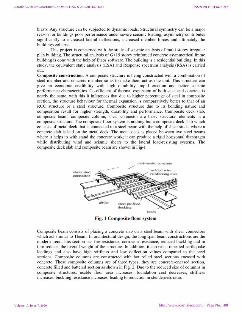
blasts. Any structure can be subjected to dynamic loads. Structural symmetry can be a major reason for buildings poor performance under severe seismic loading, asymmetry contributes significantly to increased lateral deflections, increased member forces and ultimately the buildings collapse. This project is concerned with the study of seismic analysis of multi storey irregular plan building. The structural analysis of G+15 storey reinforced concrete asymmetrical frame building is done with the help of Etabs software. The building is a residential building. In this study, the equivalent static analysis (ESA) and Response spectrum analysis (RSA) is carried out. Composite construction: A composite structure is being constructed with a combination of steel member and concrete member so as to make them act as one unit. This structure can give an economic credibility with high durability, rapid erection and better seismic performance characteristics. Co-efficient of thermal expansion of both steel and concrete is nearly the same, with this it inferences that due to higher percentage of steel in composite section, the structure behaviour for thermal expansion is comparatively better to that of an RCC structure or a steel structure. Composite structure due to its bonding nature and composition result for higher strength, durability and performance. Composite deck slab, composite beam, composite column, shear connector are basic structural elements in a composite structure. The composite floor system is nothing but a composite deck slab which consists of metal deck that is connected to a steel beam with the help of shear studs, where a concrete slab is laid on the metal deck. The metal deck is placed between two steel beams where it helps to with stand the concrete work; it can produce a rigid horizontal diaphragm while distributing wind and seismic shears to the lateral load-resisting systems. The composite deck slab and composite beam are shown in Fig-1
Composite beam consists of placing a concrete slab on a steel beam with shear connectors which act similar to Tbeam. In architectural design, the long span beam constructions are the modern trend; this section has fire resistance, corrosion resistance, reduced buckling and in turn reduces the overall weight of the structure. In addition, it can resist repeated earthquake loadings and also have high stiffness and low deflection values compared to the steel sections. Composite columns are constructed with hot rolled steel sections encased with concrete. These composite columns are of three types; they are concrete-encased section, concrete filled and battered section as shown in Fig. 2. Due to the reduced size of columns in composite structures, usable floor area increases, foundation cost decreases, stiffness increases, buckling resistance increases, leading to reduction in slenderness ratio.
ISSN NO: 1934-7197
http://www.journaleca.com/ Page No: 180
JOURNAL OF ENGINEERING, COMPUTING & ARCHITECTURE
Volume 10, Issue 7, 2020

Shear Connector is the main component in the composite floor system which transfers the shear between the concrete slab and the steel beam to the steel beam. Shear connectors are integrated to improve the compressive capacity of concrete slab and steel beam and in turn it improves load carrying capacity as well as rigidity of shear connector. Based on their suitability many types of shear connectors are available as shown in Fig. 3.
2. RELATED WORK [1] Sigmund A. Freeman.,proposed the concept of response spectra for design engineers not familiar with their significance and to summarize a variety of uses that can be applied for purposes such as rapid evaluation for a large inventory of buildings, performance verification of new construction,evaluation of existing structures for seismic vulnerability, and post-Earthquake estimates of potential damage of buildings.When earthquake ground motion data is available, the use of response spectra can be very useful in understanding how buildings perform and to identify deficiencies and damage potential. Response spectrum techniques allow engineers to visually imagine how buildings will perform during major damaging earthquakes. It is recommended that researchers and design professionals put more effort into detailed examinations of individual building response records. Luigi Di Sarno et al. [2] proposed the fundamental structural response characteristics and technological issues of composite steel and concrete systems. It assesses the pros and cons of composite structural systems and investigates the efficacy of beam-column members. Design rules for composite constructions are presented and discussed in details in order to get deep insight into their background. Composite steel and concrete systems are a viable alternative to both bare steel and reinforced concrete structures. They exhibit enhanced stiffness, strength and ductility. Composite frames benefit of the improved performance of steel and concrete columns; beams
ISSN NO: 1934-7197
http://www.journaleca.com/ Page No: 181
JOURNAL OF ENGINEERING, COMPUTING & ARCHITECTURE
Volume 10, Issue 7, 2020

are generally in bare steel to yield at an early stage in compliance with the capacity design rules. [3] Kasliwal N. A“Effect of Numbers And Positions of Shear Walls on Seismic Behaviour of Multistoried Structure”(2016). The purpose of this study has been to analyze effect of the numbers and position of the shear walls on the seismic behaviour of multi-storeyed structures. For this, ETABS software used, a Equivalent static and Response Spectrum used. Dynamic analysis has been carried out to know about the deformations, natural frequencies, and time periods, floor responses displacements. . The models that have been studied is 10 storey Building for four types of model with three types of soil. with additional shear walls with the proper position of which have been created in ETABS.
Fig 4 : Plan for Bare frame Model 1( M1) Fig 5 : Plan for complete shear wall Model 2( M2)
[4] Ravikumar C M et al,”Effect of Irregular Configurations on Seismic Vulnerability of RC Buildings” (2012). The present paper made an attempt to study two kinds of irregularities in the building models namely plan irregularity with geometric and diaphragm discontinuity and vertical irregularity with setback and sloping ground. These irregularities are created as per clause 7.1 of IS 1893 (part1)2002 code. In Oder to identify the most vulnerable building among the models considered, the various analytical approaches are performed to identify the seismic demands in both linear and nonlinear way. It is also examined the effect of three different lateral load patterns on the performance of various irregular buildings in pushover analysis.
[5] Mahesh Suresh Kumawat, “Analysis and design of multistory building using composite structure “(2014). Steel concrete composite development implies the concrete slab is associated with the steel beam with the assistance of shear connectors, so they go about as a solitary unit. In the present work steel concrete composite with RCC alternatives are considered for near investigation of G+9 story commercial building which is arranged in seismic tremor zone-III and for earthquake loading, the arrangements of IS: 1893 (Part1)- 2002 is considered. A three dimensional demonstrating and examination of the structure are completed with the assistance of SAP 2000 software. Equivalent Static Technique for Examination and Response spectrum investigation strategy are utilized for the examination of both Composite and RCC structures. The outcomes are thought about and found that composite structure more practical).
3. PROPOSED WORK The present work deals with the evaluation of seismic characteristics for multi-storey residential reinforced concrete and composite building. The main focus of attention is to find
ISSN NO: 1934-7197
http://www.journaleca.com/ Page No: 182
JOURNAL OF ENGINEERING, COMPUTING & ARCHITECTURE
Volume 10, Issue 7, 2020

out the behaviour of buildings (RCC and Composite) with different locations of shear walls using Equivalent static analysis and Response spectrum analysis.
4. IMPLEMENTATION It is an attempt to investigate the effect of Irregular plan configuration for multistoried reinforced concrete building model. This project mainly emphasizes on analysis of a multi-storey building (G+15) which is irregular both in plan. Modelling of 15 storeyed R.C.C. framed building will be done on the ETABS 2015 software for analysis. Post analyses of the structure such as Maximum Storey Displacement, Base Shear, Storey Drift, Maximum base reactions, Self weight are computed and then compared for all the analysed cases. Here the study is carried out for the behaviour of G+15 Multistorey Storied Buildings, Floor height provided as 3.35m and also properties are defined for the building structure. The model of buildings is created in ETABS software. The seismic zone considered is zone v and soil type is medium.The modelling of building is done for Indian Seismic Zone V, IS 1893-2002.For given structure, loading with applied loads includes live load, earthquake load and dead load are according to IS 875 part II, IS1893-2002, IS 875 part I respectively. Analysis is carried out by Response Spectrum Analysis using ETABS software. The analysis is carried out to determine maximum node displacement and base shear. After analysis, results are obtained in the form of graphs which are in turn observed to form conclusions.
ISSN NO: 1934-7197
http://www.journaleca.com/ Page No: 183
JOURNAL OF ENGINEERING, COMPUTING & ARCHITECTURE
Volume 10, Issue 7, 2020

Seismic analysis codes of the building prescribe the method of analysis based on whether the building is regular or irregular. Majority of the codes recommends the use of linear static analysis for symmetric and selected class of regular buildings. The code suggests the use of dynamic analysis methods for the irregular configurations of the buildings The codes of seismic analysis prescribes the different methods to carry out lateral load analysis, during the analysis and design the infill wall and it's effect is usually ignored. In the present study, the code for seismic analysis is followed for the lateral load analysis. ETABS is used for performing the analysis.
5. DESCRIPTION OF THE MODEL
1. Here in this study we have considered ten models for the study. 2. Conventional RCC building with beams and columns (Bare frame model). 3. Bare frame model + Shear walls @ Core location of building. 4. Bare frame model + Shear walls parallel to X axis. 5. Bare frame model + Shear walls parallel to Y axis. 6. Bare frame model + Shear walls parallel to both X and Y axis. 7. Composite building with beams and columns (Bare frame model). 8. Composite Bare frame model + Shear walls @ Core location of building. 9. Composite Bare frame model + Shear walls parallel to X axis. 10. Composite Bare frame model + Shear walls parallel to Y axis. Composite Bare frame model + Shear walls parallel to both X and Y axis.
6. DESIGN OF BUILDING
Bare frame model + Shear walls @ Core location of building.
Fig 6 : PLAN Fig 7 :3D Elevation
ISSN NO: 1934-7197
http://www.journaleca.com/ Page No: 184
JOURNAL OF ENGINEERING, COMPUTING & ARCHITECTURE
Volume 10, Issue 7, 2020

Composite building with beams and columns (Bare frame model).
Fig 8 : PLAN Fig 9 :3D Elevation Composite Bare frame model with Shear walls @ Core location of building.
Fig 10 : PLAN Fig 11:3D Elevation
7. RESULT AND ANALYSIS Fundamental Time period :
From the chart it is seen that, the Fundamental Time Period is highest for the bare frame model (Model 1) less for the model 10 i.e., Composite bare frame model with Shear walls provided parallel to X and Y direction. The Fundamental Time Period is found to be decrease when the influence of shear wall is considered. The Fundamental Time Period is highest for the RCC model 5 with shear walls parallel to X and Y axis and less for the Composite model 10 with Shear walls parallel to X and Y direction. The percentage decrease in Time period for model 10 is 61.68% when compared to model 5 (RCC Bare frame model with shear walls parallel to X and Y axis).
ISSN NO: 1934-7197
http://www.journaleca.com/ Page No: 185
JOURNAL OF ENGINEERING, COMPUTING & ARCHITECTURE
Volume 10, Issue 7, 2020

Table 1 : Time period of Various RCC and Chart 1: Time periods of various RCC and Composite models. Composite models. Maximum storey displacement
Chart 2: Maximum storey displacement of RCC & Chart 3: Maximum storey displacement of RCC & Composite models for ESA along EQ-X Composite models for ESA along EQ-Y
Chart 4: Maximum storey displacement of RCC & Chart 5: Maximum storey displacement of RCC & Composite models for RSA along EQ-X Composite models for RSA along EQ-Y
From the chart it is observed that, the maximum storey displacement is more for model 1 and less for model 10. The permissible Maximum displacement as per IS code is given by L/500=53130/500=106.26mm where L is total height of the building.Model 1,Model 2 exceeds permissible limits in ESA and RSA. whereas other 3 models are within the permissible limits. The Storey displacement is maximum for model 5 i.e., RCC bare frame model with shear walls provided parallel to X and Y axis compared to Composite Bare frame model with shear walls parallel to X and Y axis (model10). The percentage decrease in displacement for ESA and RSA are 72.22% and 90.88% in X direction and Y directions
ISSN NO: 1934-7197
http://www.journaleca.com/ Page No: 186
JOURNAL OF ENGINEERING, COMPUTING & ARCHITECTURE
Volume 10, Issue 7, 2020

respectively for model 10 when compared to model 5. The reduction in storey displacement shows that the model 10 is stiff and less flexible.
The story displacement results are summarized as follows
Table 2 : Maximum storey displacement of RCC and Composite models.
Storey Drift
Table 3 : Storey Drift of RCC and Composite models
Chart 6 : Storey drift of RCC and Composite models for Chart 7 : Storey drift of RCC and Composite models for
ISSN NO: 1934-7197
http://www.journaleca.com/ Page No: 187
JOURNAL OF ENGINEERING, COMPUTING & ARCHITECTURE
Volume 10, Issue 7, 2020

ESA along X- direction ESA along Y- direction
Chart 8 : Storey drift of RCC and Composite models for Chart 9: Storey drift of RCC and Composite models for RSA along X- direction RSA along Y- direction
From the charts it is seen that ,the storey drift is maximum for RCC bare frame model (model1) and minimum for model 10 i.e., Composite bare frame model with shear walls provided parallel to X and Y axis. All the storey dift values are within the permissible limits i.e.,0.004times the height of each storey 0.004x3.35=0.0134m=13.4mm. The percentage decrease in storey drift for model 10 is 72.20% and 91.39% For ESA in X and Y directions respectively when compared to model 5. The self weight of RCC and Composite building The self weight includes Dead load, lift load, wall load, floor finish and parapet wall load. The Self weight of RCC Bare frame model is 116877.8 kN and the Self weight of Composite Bare frame model is 89574.76kN.The results are obtained from ETABS Software. The results shows that the Composite structure is 23.36% lighter than the RCC structure. As a result the foundation cost of composite structure decreases as compared to RCC structure, The RCC Structure member sizes gets reduced when the same RCC plan is analysed using Composite structure. The reduction in member sizes is shown below:
Table 4 : RCC and Composite structure member sizes
ISSN NO: 1934-7197
http://www.journaleca.com/ Page No: 188
JOURNAL OF ENGINEERING, COMPUTING & ARCHITECTURE
Volume 10, Issue 7, 2020

8. OBSERVATION
1) The Fundamental Time Period is highest for the RCC model 5 with shear walls parallel to X and Y axis and less for the Composite model 10 with Shear walls parallel to X and Y direction. The percentage decrease in Time period for model 10 is 61.68% when compared to model 5 (RCC Bare frame model with shear walls parallel to X and Y axis).
2) The Storey displacement is maximum for model 5 i.e., RCC bare frame model with shear walls provided parallel to X and Y axis compared to Composite Bare frame model with shear walls parallel to X and Y axis (model10). The percentage decrease in displacement for ESA and RSA are 72.22% and 90.88% in X direction and Y directions respectively for model 10 when compared to model 5.
3) The storey drift is maximum for RCC bare frame model with shear walls provided parallel to X and Y axis (model 5) compared to Composite model having shear walls parallel to X and Y axis (model 10). The percentage decrease in storey drift for model 10 is 72.20% and 91.39% For ESA in X and Y directions respectively when compared to model 5.
4) It is observed that the Composite bare frame model with shear walls parallel to X and Y axis (model 10) has minimum base shear value compared to model 5 in Equivalent static analysis (ESA) and response spectrum analysis (RSA) in X- direction, The percentage decrease in Base shear for model 10 in X direction is 52.56% for ESA and 53.16% for RSA when compared to model 5.
5) The Self weight of Composite and RCC Structures are 89574.76kN and 116877.8 kN respectively. The results shows that the composite structure is 23.36% lighter than the RCC structure. As a result the foundation cost of composite structure decreases as compared to RCC structure.
6) The results shows that the model 10 i.e., Composite bare frame model with shear walls
provided parallel to X and Y axis is best economical model due to reduction in frame sizes, less displacement, less storey drift ,less base shear and less time period.
7) The RCC Structure member sizes gets reduced when the same RCC plan is analysed
using Composite structure.
9. CONCLUSIONS
The maximum storey displacement, storey drift, Base shear and Time period is more for the RCC Bare frame model when compared to the Composite bare frame model.The maximum storey displacement, Storey drift , Base shear and Time period is more for model 5 i.e., RCC Bare frame model with shear walls provided parallel to X and Y direction and less for model 10 i.e., Composite Bare frame model with shear walls provided in both X and Y directions.
The Fundamental Time Period, maximum storey displacement, Storey drift and Base shear for model 10 is less compared to all other models which shows that the model 10 is stiff, less flexible to vibrate against lateral force.The self-weight of Composite structure is less as compared to RCC structure which helps in reducing the foundation cost.The
ISSN NO: 1934-7197
http://www.journaleca.com/ Page No: 189
JOURNAL OF ENGINEERING, COMPUTING & ARCHITECTURE
Volume 10, Issue 7, 2020

Base shear for composite structure is less as compared to RCC structure because the self-weight of RCC structure is more as compared to composite structure.
REFERENCES
1. Dhiraj.V.Narkhede “Performance of Shear Wall Building at Various Positions by Using Pushover Analysis” International Journal of Research in Advent Technology (IJRAT)
(EISSN:2321-9637) Special Issue National Conference “CONVERGENCE 2016”, 06th- 07th April 2016
2. Lakshmi K.O.”Effect of shear wall location in buildings subjected to seismic loads”ISOI
Journal of Engineering and Computer science Volume 1 Issue 1; Page No. 07-17. 3. Kasliwal N. A “Effect of Numbers And Positions of Shear Walls on Seismic Behaviour
of Multistoried Structure”International Journal of Science, Engineering and Technology Research (IJSETR) Volume 5, Issue 6, June 2016.
4. Fazal U RahmanMehrabi, “Effects of Providing Shear wall and Bracing to Seismic Performance of Concrete Building”International Research Journal of Engineering and Technology (IRJET) e-ISSN: 2395 -0056Volume: 04 Issue: 02 | Feb -2017
5. Ravikumar C M et al,”Effect of Irregular Configurations on Seismic Vulnerability of RC Buildings” Architecture Research 2012, 2(3): 20-26 DOI: 10.5923/j.arch.20120203.01.
6. Mahesh Suresh Kumawat,“Analysis and design of multistory building using composite structure “International Journal of Structural. & Civil Engineering Research. ISSN 2319-6009 Vol. 3, No. 2, May 2014.
7. Murtuza S. Aainawala “Behaviour of G+15 RCC and composite structure” International Journal of Innovative and Emerging Research in Engineering Volume 3, Special Issue 1,ICSTSD 2016.
8. Suryanarayana M “Analysis of G+15 RCC and Composite structure having soft storey at ground level by response spectrum and equivalent static methods using ETABS 2013” International Research Journal of Engineering and Technology (IRJET) e-ISSN: 2395 - 0056 Volume: 02 Issue: 03 | June-2015
9. Nitish A. Mohite “Comparative Analysis of RCC and Steel-Concrete-Composite (B+G+11 Storey) Building” International Journal of Scientific and Research Publications,Volume 5, Issue 10, October 2015 1 ISSN 2250-3153.
10. Varsha Patil “Comparative Study on Dynamic Analysis of Composite, RCC & Steel Structure” International Journal of Engineering Technology, Management and Applied Sciences August 2015, Volume 3, Issue 8, ISSN 2349-4476
ISSN NO: 1934-7197
http://www.journaleca.com/ Page No: 190
JOURNAL OF ENGINEERING, COMPUTING & ARCHITECTURE
Volume 10, Issue 7, 2020