use of finite element analysis in roadside hardware …
TRANSCRIPT

61
USE OF FINITE ELEMENT ANALYSIS IN ROADSIDE HARDWARE DESIGN
Malcolm H. Ray University of Iowa
THE PAST
Introduction
Roadside safety research has progressed through several phases during the past 40 years. The first phase, accomplished in the years around 1960, was to recognize that there was a problem and that it was possible to improve the safety of roadways using engineering design.
In the infancy of roadside safety research it was possible to make significant improvements in safety just by using common sense and basic engineering judgement: keep the vehicle from leaving the road, rolling over, or underriding the barrier; make sure the occupant stays inside the vehicle and nothing harmful penetrates into the occupant compartment. Many of the most common guardrail systems date from this early phase.
The next stage took place in the 1970s and 1980s. More difficult problems were attacked like developing guardrail terminals, transitions and crash cushions. Roadside hardware was developed to address a broad range of specific applications and site conditions. While judgement and intuition were still valuable tools, crash testing became the primary method for exploring the collision performance of barriers. Designers, using their intuition about impact events, were able to produce many useful designs, most of which are still in service today.
Unfortunately, the era of intuitive design in roadside safety is over. The problems that have persisted over the past several decades are the most difficult, most complex and most demanding problems - guardrail terminals, side impacts, and non-tracking impacts and vehicle-barrier interaction problems to name just several. The roadside safety community is now entering a new phase of research where the effort and resources required to produce a successful roadside hardware design have increased as have the expectations of the public. Further improvements in roadside safety will require the use of the best analytical tools available in addition to era.sh testing and intuition.
This paper discusses only one particular analytical method: non-linear dynamic finite element analysis. Vehicle handling simulation codes represent another important area of research but these methods are not discussed in this paper.(J)
History
The use of analytical methods are not new to roadside hardware design. Perhaps one of the most successful applications of finite element technology to roadside safety was the very first. Researchers at Cornell Aeronautical Laboratory investigated the mechanics of vehicle-barrier collisions for the New York Department of Public Works in the early 1960s.(2) Simple analytical models were developed using springs, dash-pots, beams and links to examine the dynamics of vehicles and the strength of barriers. This study was very successful, resulting in evaluations of many at-the-time common guardrails. This study was the first to recognize several now-commonly recognized safety problems with guardrails like (1) the importance of the rail separating from the post to prevent vehicle vaulting, (2) the potential for wheel snagging to occur on strong post guardrails and (3) the potential for pocketing when strong posts are combined with relatively weak rails. This research project was instrumental in improving the designs of the W-beam median barrier and the box beam guardrail designs used in New York to this day as well as the elimination of some poor designs like strongpost cable guardrails.(3, 4)
The New York Department of Public Works and the Cornell Aeronautical Laboratory also collaborated on using analytical methods for predicting the response of vehicles when impacting rigid barriers like the concrete safety shape.(5) This work eventually lead to the development of the Highway Vehicle Object Simulation Model (HVOSM) which has been widely used in the roadside safety community.(6)
The Barrier VII program was developed in the 1970s and has been widely used to simulate impacts with flexible barrier systems.(7) The program is a twodimensional code that contains a variety of simple elements like springs, dash-pots, links, posts, and beams. While the relative simplicity of the code and its models made it very useful for many types of impacts, there were significant limitations to the types of simulations that could be performed because the code represented only two dimensions.
A series of ill-fated projects were initiated in the 1980s to try and develop the next generation of barrier analysis finite element codes. The codes GUARD, CRUNCH and NARD were the result of these efforts.

62
(8, 9, 10) Unfortunately, none of these codes ever -~~----1 ... 1 - -- .r..1_ . -- - " - - ' --- ~ 1 • • . o,a1.11'-'U llili.:I \..UllUUCU\..C Ul. QllcUy:n:t UUV lU d Vi:111Cty Ul
problems including coding errors, poor analytical formulations, and restrictive assumptions. The roadside safety community's negative experience with the NARD and GUARD programs has left a lasting pessimism about the utility of analytical methods in roadside safety hardware design and evaluation.
In 1991 the FHW A sponsored three projects to recommend a plan for developing improved capabilities for analytical simulations of roadside hardware collisions. (11, 12, 13) All three plans recommended abandoning special-purpose analysis codes like NARD, GUARD, Barrier VII and HVOSM in favor of the general-purpose non-linear finite element program DYNA30. (14) In a relatively short period of time, the roadside safety community has gom: from having virtually no capabilities and experience with general-purpose codes like DYNA3D to building a network of Universities, a national laboratory, several offices in government agencies, and a variety of commercial software vendors.
While some aspects of the simulation effort have been frustratingly slow there has been an exceptional amount of progress in the past four years. Analytical methods are at a critical juncture where they can begin to make a dramatic contribution to the improvement of roadside safety.
THE PRESENT
Benefits of Safety Research
Despite the increasing difficulties, there is still a need for further roadside safety research. Two particular results of safety research demonstrate its continued utility:
• Reductions in the fatalities and mJuries experienced on the roadside and a consequent reduction of accident costs, and
• Protecting the public's investment in roadside safety hardware.
Both FHW A and NHTSA share the goal of reducing the number, severity, and cost of highway accidents. In the past, NHTSA has concentrated on vehicle-to-vehicle collisions and occupant protection technology, leaving single-vehicle roadside accidents largely to FHW A to address. Single-vehicle accidents occurring off the roadway accounted for 1.4 million accidents in 1992, this represents more than 20 percent of all motor vehicle accidents. (15) Accidents occurring on the roadside represent a significant segment of all motor vehicle accidents. FHW A and NHTSA, therefore, share responsibility for 20 percent of the motor vehicle
accident problem. Some emerging accident types, like :;iuc imp<H.:t:; witn narrow oojeCCS ana Coe inceracrion OI wedge-shaped vehicles with roadside hardware, probably cannot be improved without a joint effort by both the roadside and vehicle design community.
Once installed, roadside hardware has a service life of 20 or even more years. Vehicles, in contrast, generally do not last more than 10 years and automobile manufacturers can radically change the characteristics of the vehicle population very quickly. The vehicle manufacturing industry can build vehicles that meet all applicable NHTSA safety standards but may not perform correctly with the majority of guardrails, bridge rails and other roadside hardware. For example, recent testing has shown that full-size pickup trucks roll over in 25 degree, 100 km/hr impacts with some strong-post Wbeam guardrails. The light truck class of vehicles is rapidly approaching 50 percent of the vehicle fleet. (16) This type of longitudinal barrier is the primary guardrail in nearly every state in the United States, lining hundreds of thousands of miles of roadway. Minivans did not even exist a decade ago yet now they represent about 10 percent of the vehicle population. ( 16) No crash tests of minivans and roadside hardware have ever, to the author's knowledge, been performed so the roadside design community has no clear understanding of how such vehicles are performing in the field in impacts with roadside safety hardware. Public agencies cannot afford the investment required to modify hundreds of thousands of miles of longitudinal barrier to continuously chase the moving-target of vehicle characteristics. Even if public agencies could afford it, the time required to retrofit this much hardware would be enormous and the changes could be obsolete before they were completed.
State governments have a substantial investment in roadside safety hardware. Currently there are no standards that ensure that this investment is not made obsolete by rapid changes in the vehicle fleet. One way to protect the public's investment in roadside safety hardware would be to perform a "standard" test of new productio!! vehides o!! selected "standard" item.s of roadside safety hardware like the strong-post W-beam guardrail and the concrete safety shape (the so-called New Jersey shape). Given the relatively high degree of standardization in the roadside barrier community, it seems reasonable to require that vehicle manufacturers demonstrate that new vehicles will interact correctly with common types of roadside safety hardware.
Vehicle-Barrier Interaction
Occasionally, roadside safety researchers run a full-scale crash test and observe an unexpected catastrophic failure that, after further investigation, seemed to be caused
--

more by some feature of the test vehicle than the roadside hardware. This would prompt the question, "what is being tested, the hardware or the vehicle?" These types of vehicle-related failures have been observed more frequently during the past several years as researchers began to perform more tests with pickup trucks to comply with NCHRP Report 350 and as tests with vehicles other than passenger cars became more common. ( 17) It is becoming increasingly difficult to treat the vehicle, the roadside barrier and the roadside geometry as independent elements that can be designed with little thought about the other two.
Side impacts with narrow objects like trees and utility poles accounted for more than 8 percent of all traffic related fatalities and 20 percent of all singlevehicle run-off-road accidents in the period between 1980 and 1985. (18) Better warrants for removing selected trees and relocating utility poles would reduce this somewhat but significant changes will require the attention of both the vehicle design community and the roadside safety and roadway design communities. Side impacts are also a problem with breakaway hardware like luminaire supports, small signs and guardrail terminals. (19) Testing has shown that it is nearly impossible to weaken a guardrail terminal sufficiently to improve side impact performance without destroyµig the terminal's effectiveness in end-on impacts. Improved performance for side impacts with guardrail terminals (thought to be about 1/3 of all guardrail terminal collisions) will require improvements to the side structure of vehicles as well as better termjnal design. (18)
Poor performance has been observed recently in pickup truck impacts with guardrails and guardrail terminals. (20) A preliminary evaluation of these tests suggests the problem may be caused by (1) the inertial and stability properties of the truck, (2) particular aspects of the suspension design that promote failure in barrier collisions, and (3) the short overhang distance between the front bumper and front wheel. While improvement in the performance of some roadside hardware devices can probably be achieved for some specific impact conditions, this class of vehicles appear to have serious performance problems in barrier impacts that might only be solvable by improving the design of the vehicle or at least better understanding the interaction between the vehicle and barrier. Problems with the pickup truck suggest that there may be similar problems with the new cab-forward passenger car designs.
Aerodynamically shaped front ends on most new vehicles have been shown to perform catastrophically in end-on impacts with terminals. (21) Modifications to the terminal noses have not yet significantly improved the results. Anecdotal evidence has appeared in the literature to show that there can be problems with
63
FIGURE 1 Roadside safety hardware development cycle.
aerodynamically styled vehicles under-riding some types of guardrails. (22)
These are just a few examples where the changing geometry and properties of vehicles have made obsolete barriers that once performed quite well with the vehicle fleet of five and ten years ago.
Roadsid~ Hardware Design
Finite element analysis should be incorporated as an integral part of the roadside safety hardware design process. In today's funding climate, with today's difficult research problems it is just not feasible to expect to test every impacl scenario. Figure 1 shows a representation of the roadside safely research cycle: design, simulation, test, implement, and in-service evaluation. Currently a researcher designs hardware and tests it, repeating and refirung until either a successful design is produced or fundjng evaporates. Hardware is installed based on the results of these research and development tests. Even though the need for in-service evaluation is universally recognized, an effective means of accomplishing an inservice evaluation has yet to be found so the "loop" in practice is seldom ever closed. The subject of this paper, however, is the increasing importance and utility of the analysis phase of the roadside hardware development cycle.
When designs are simple an analysis phase is often unnecessary. As designs become more complicated, however, an explicit analysis step should be performed. Analysis can help identify and correct problems in the design prior to testing. Several issues wiJl necessitate

64
the increased use of analytical methods in roadside
• Tests cannot provide enough information about the loads, accelerations, stress and strains of barrier components to develop designs based on the mechanical behavior of barrier components.
• Repetitive tests are expensive and not well suited to parametric analysis.
• It is impractical to test with the full range of vehicles that should be examined.
• It is not possible to examine the affects of a variety of test conditions like non-tracking pre-impact trajectories, side impacts, and driver braking and steering during impact.
There are three steps in integrating finite element analysis into the design process:
• Simulations that explain the results of tests, • Simulations that predict the results of tests, and • Simulations that evaluate impact scenarios that
are untestable.
The first step is to use finite element analysis to examine tests chat have already been run. Such analysis can be used to examine the stresses and strains, accelerations and velocities, and failure mechanisms in a particular impact scenario in order to gain a better understanding of the impact event. This improved understanding can then be used to develop better design alternatives, examine lhe sensitivity of particular design elements to impact conditions or variations in material properties, or to estimate evaluation criteria. Currently, nearly all the work in using finite element methods in roadside hardware fall into this category.
The next stage is to use; finite element analysis to predict the likely outcome of a full-scale crash test before the test is performed. This might be used to pick the most promi ing of several possible design alternatives, to identify the most critical crash test, or to identify the worst-case test"vehicle for a particnl:ir pie(·e. of hardware.
The last stage is to use finite element analysis to evaluate the performance of hardware in situations that cannot be tested. Examples of this type of use incluuc examining non-standard impact conditions like yawing prior to impact, braking and steering during impact, traversing a non-level terrain prior to impact. Simulations could also be used to test non-standard vehicles or prototype vehicles. This use of finite element analysis will enable engineers to examine collisions that would be impossible to test and thereby design hardware that performs more reliably under a wide range of realworld condjtions.
The emerging roadside safety environment will require roadside hardware that performs with a wide range of vehicle types over a wide range of impact conditions. While full-scale crash testing will always be a crucial part of roadside safety research it can no longer remain the sole tool for exploring the performance of the roadside.
Analysis Codes
FHWA, NHTSA and LLNL have actively promoted integrating nonlinear finite element technology into the roadside hardware design and evaluation process. As with any large technical program there have been both successes and failures, exploited and missed opportunities, consensus and dissent.
The available analysis codes, DYNA3D and LSDYNA3D, can be used to solve many roadside hardware design problems. Analysts have not yet come close to folly exploiting the capabilities of these codes in the area of roadside hardware. A series of meetings were held in 1992 and 1993 to assemble simulation users and experts and discuss approaches to take in integrating finite element methods into roadside hardware design. While much useful information was exchanged these meetings largely failed and were ultimately discontinued because they simply generated shopping-lists of "enhancements" rather than focusing on how finite element techniques could be used to produce useful results immediately. Focusing on "enhancements" to the numerical codes at this stage is unnecessary, premature and it is a distraction from the real task at band - improving the design of roadside safety hardware. Enhancements should be driven by the practical problems of hardware designers rather than by the speculation of researchers.
Vehicle Models
When the FHWA began its effort to use DYNA3D in roadside hard'.vare assessment, no one a.-iticipatcd how difficult it would be to obtain vehicle models. Table 1 shows all the vehicle models that are publicly available for roadside hardware research along with some summary information. These models were developed by a variety of organizations for a variety of purposes so the size, complexity and speed vary considerably. Size in Table 1 is defined as the number of elements in the vehicle model. Although characterizing models by the number of elements alone does not give a complete picture of the model's likely performance, it does serve as a good first indicator of model complexity. The model speed is perhaps the best characteristic to examine, where speed is the amount of event time (in

TABLE 1 F4 VEHICLE MODELS DEVELOPED FOR USE IN ROADSIDE HARDWARE ANALYSIS
Model Size* Speedt Preprocessor
Saturn 2,260 100 Ingrid
Honda 10,100 8 Ingrid
820C 5,200 20 Ingrid/ TrueGrid
Taurus 28,350 2 Patran
C-1500 35,100 0.67 Patran
*Size is the size of the model in terms of the number of elements. tspeed is the estimated amount of simulated time in msec per CPU hours on an IBM RISC 6000 Model 390 workstation.
FIGURE 2 Model of a 1991 GM Saturn.
msec) that is simulated in one CPU hour of computation. As shown in Table 1, speeds of the available models vary from 0.67 msec/CPU hrs for the C-1500 pickup truck to 100 msec/CPU hrs for the Saturn. Clearly an analyst pays a heavy price in increased computation time when using the larger vehicle models. While a high degree of complexity may be required for designing vehicles, evaluating occupant restraint systems or assessing the likelihood of occupant compartment intrusion, it is still unclear how complex a vehicle model must be to provide good results in roadside hardware simulations.
The first model developed for roadside hardware research was a simple model of a 1991 GM Saturn shown in Figure 2. (23) This model was developed for FHW A by physically measuring the vehicle and building a simple mechanical analogue. The model was used to simulate a frontal impact with a slip-base luminaire support, a rigid wall, and a U-post sign support to demonstrate the utility and feasibility of using nonlinear
65
FIGURE 3 Model of a 1981 Honda Civic.
finite element analysis. This model was the first successful application of DYNA3D to a roadside safety hardware problem.
Concurrently with the effort to develop the Saturn model, the FHW A sponsored the development of a frontal impact model of a 1981 Honda Civic, a vehicle frequently used in past crash tests. The model, shown in Figure 3, was developed by a firm that specializes in developing vehicle models for the automotive industry. The model was developed using a forensic approach; the vehicle was taken apart, photographed, scanned, measured and otherwise documented. These data were then used to build the geometric representation and material characterization of the vehicle. There were numerous problems with this vehicle when other researchers tried to use it for roadside safety applications. Extensive additional work was required before reliable results could be obtained. (24)
A simple model of an NCHRP Report 350 820C vehicle, shown in Figure 4, was developed for FHW A to try and obtain a vehicle model quickly that would allow researchers to focus on developing roadside hardware rather than building vehicle models. (25) The model was intended to be relatively generic although it was largely based on a 1990 Ford Festiva. The model was initially developed for frontal impacts into narrow objects but it is also being used for frontal impacts with guardrail terminals and redirectional collisions with guardrails and bridge railings.
FIGURE 4 Model of an 820C vehicle.

66
FIGURE 5 Model of a 1991 Ford Taurus.
FIGURE 6 Model of a 1994 Chevrolet C-1500 pickup truck.
NHTSA sponsored the development of a 1991 Ford Taurus, also produced by an automotive crashworthiness analysis company. (26) This model has been extensively modified as it was used in a variety of new situations not foreseen when it was originally developed. (27) This model has not yet been used in roadside hardware simulations but has been extensively used in simulations of frontal rigid wall impacts, off-set frontal vehicle-tovehicle impacts, and frontal narrow object impacts and occupant compartment intrusion studies. There is also a version of this model available for narrow-object side impact collisions. NHTSA is also sponsoring the development of models of a Dodge Intrepid and a GM Saturn at West Virginia University.
The most recent vehicle model to be developed, shown in Figure 6, is a 1994 ChevroJct C-1500 pickup truck. This model, which was jointly developed by NHTSA, FHWA, and George Washington University, was also developed using a forensic approach where the vehicle was disassembled, scanned and connections were meticulously documented. The result was a very large, very complicated model that, while being detailed, is difficult to use unless one has sophisticated computing facilities and is prepared for long run times. The Chevrolet C-2500 is the pickup truck conforming to the 2000P vehicle designated in Report 350. The differences
between the C-1500 and C-2500 are relatively minor: hco.-.-;c, i>u:>j.i.Ou:>luu, 1<11!!,v• i.i1v:s i:tUU i:1 :siighLiy ilmg~r wheel base on the C-2500. FHWA is currently sponsoring an effort to simplify this model so that it is more useful to roadside hardware researchers using DYNA3D on typical engineering workstations.
The most serious obstacle to using finite element methods in designing roadside hardware today is the scarcity of the right kind of vehicle models. There has been a presumption that the biggest, most complicated models would by definition provide the most accurate solution. Given the rapid advance of computing technology, the fact that large complex models require very large investments in computing hardware should only he a shnrt-term irritation according to this view. While this may prove true in the long run, if finite
lt:mt:nt analysis cannot begin to prouuce practical results that solve operational hardware problems almost immediately, it is unlikely that a program in roadside hardware finite element analysis will survive.
Modelling vehicles using non-linear finite element analysis is not in itself new, in fact automobile manufacturers and NHTSA have been making extensive use of DYNA3D and LS-DYNA3D for nearly a decade. Using this type of analysis in roadside hardware design, however, is new and it is not necessarily true that the same techniques that worked in the aut motive de ign arena will work in designing roadside afely hardware. Roadside hardware impact simulations must address inertial properties of the vehicle to a much more detailed degree. The roll-pitch-yaw rotations of the vehicle are a very important aspect of a roadside hardware test since these indicate the stability of the vehicle. Typical FMVSS tests do not generally involve rotational degrees of freedom to any great extent so modelling these features has not generally been a priority. Until very recently, there was no simulations of a vehicle in an angled impact where the rotation of the vehicle was physically reasonable. The affect of the suspension system on the kinematics of the vehicle is also generally not considered in vehicle models generated hy th~ a11tomobile industry yet in roadside hardware impacts, the suspension effects can frequently be critically important. Laslly, catastrophic failures can be observed in full-scale crash tests that are accompanied by relatively little vehicle damage. This illustrates that the kinematics of the vehicle are more imporrant in roadside hardware simulation than they generally are in automotive crashworthiness simulations. The structural crashworthiness is seldom the deciding factor in whether a full-scale test passes or fails the Report 350 evaluation criteria.
At this time it is still unclear what types of models are needed. Some types of research, for example studying the toe-pan intrusion in a vehicle, will require large complex models of the vehicle. Other types of

FIGURE 7 32 km/hr impact of an 820C vehicle with a rigid cylindrical pole.
impacts, for example the glancing-blow impact of a guardrail terminal (Test 3-32), depend almost completely on inertia and kinematics so a very simple model would be appropriate. Determining what types of model are appropriate in different situations and how to develop and maintain these models will doubtless be a point of debate for some time. Ideally, the vehicle models used by FHWA and NHTSA should be the same. Given the difficulty and expense of building these models it would be foolish not to collaborate. There are a variety of options:
• Develop high-order models and wait for computing hardware and software advances to erode the computational penalty.
• Develop high and low-order meshes at the same time.
• Develop models specifically targeted for each application.
Each strategy has its advantages and disadvantages and it is difficult at this early stage to predict the best strategy.
Roadside Hardware Models
There have been a variety of efforts to model roadside safety hardware during the past several years despite the difficulty of obtaining vehicle models.
The first several roadside hardware applications of DYNA3D were of small car frontal impacts like the rigid pole and U-channel post simulations shown in Figure 7 and Figure 8. The rigid pole simulations are very useful for validating frontal-impact vehicle models for narrow object impacts. Flanged-channel post simulations have been performed using the Honda Civic and 820C vehicle models. The flanged-channel sign support model has been investigated by several analysts, most recently with respect to finding an appropriate method for modelling the soil. (28, 29)
FIGURE 8 32 km/hr impact of 820C vehicle with a flanged-channel sign support (Test 3-60).
67
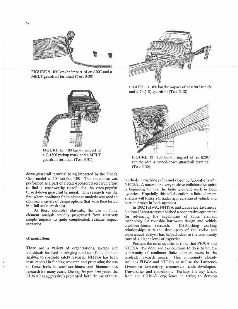
Recent poor test results of pickup trucks in impacts with several standard guardrail terminals have generated interest in simulating these types of impacts. A modified eccentric loader BCT (MELT) guardrail terminal was modelled and simulations of Report 350 Tests 3-30 and 3-32 were performed using the 820C vehicle model. The small car model was used first since there is test data available for the Test 3-30 conditions (820C - 100 km/hr - 20 degrees) which allowed the analyst to begin evaluating the performance of the model prior to investigating the performance of the pickup truck. Figure 9 shows the small car Test 3-30 impact. After the model of the MELT was found to perform well in small car impacts, the Chevrolet C-1500 pickup truck model was combined with the MELT model as shown in Figure 10. The simulation was encouraging but the vehicle did not roll, pitch, or yaw as it should have. The actual crash test resulted in a rollover whereas there were no stability problems apparent in the simulation. Further investigation found that there was a problem with the analysis code that has since been corrected although the model has not been rerun.
Performance problems have also been observed in pickup truck impacts with common guardrails like the G4(1S). As a first step toward modelling this system, an 820C vehicle impact under Report 350 Test 3-10 conditions (820C-100 km/hr-20 degrees) was modelled as shown in Figure 11. This was done so that the hardware model could be debugged and compared to existing test data prior to predict its performance in pickup truck impacts.
Some independent research (research not sponsored directly by FHW A) is also beginning to be performed as the DYNA3D code is made available to Universities and other research organizations with an interest in roadside hardware. Figure 12 shows an example of a turned-
iii
=
68
' FIGURE 9 100 km/hr impact of an 820C and a MELT guardrail terminal (Test 3-30).
FIGURE 10 100 km/hr impact of a C-1500 pickup truck and a MELT guardrail terminal (Test 3-31).
down guardrail terminal being impacted by the Honda Civic model at 100 km/hr. (30) This simulation was performed as a part of a State-sponsored research effort to find a crashworthy retrofit for the once-popular turned-down guardrail terminal. This research was the first where nonlinear finite element analysis was used to examine a variety of design options that were then tested in a full-scale crash test.
As these examples illustrate, the use of finite demeni analysis steadiiy progressed from reiauve!y simple impacts to quite complicated, realistic impact scenarios.
Organizations
There are a variety of organizations, groups and individuals involved in bringing nonlinear finite element analysis to roadside safety research. NHTSA has been instrumental in funding research and promoting the use of these tools in crashworthiness and biomechanics research for many yean;, During the past four years, the FHW A has aggressively promoted both the use of these
FIGURE 11 100 km/hr impact of an 820C vehicle and a G4(1S) guardrail (Test 3-10).
FIGURE 12 100 km/hr impact of an 820C vehicle with a turned-down guardrail terminal (Test 3-30).
methods in roadside safety and closer collaborations with NHT A. A natural and very positive collaborative spirit is beginning to link the finite element work in both agencies. Hopefully, this collaboration in finite element analysis will foster a broader appreciation of vehicle and barrier design in both agencies.
In 1992 FHWA, NHTSA and Lawrence Livermore National Laboratory estahlished a coopP-r11tive. agre.e.me!!t for advancing the capabilities of finite element technology for roadside hardware design and vehicle crashworlhiness research. Establishing working relationship with Lhe developers of the codes and experienced analysts has helped advance the community Loward a higher level of expertise.
Perhaps the most significant thing that FHWA and NHTSA have done and can continue to do is to build a community of nonlinear finite element users in the roadside research arena. This community already includes FHW A and NHTSA as well as the Lawrence Livermore Laboratory, commercial code developers, Universities and consultants. Perhaps the key lesson from the FHW A's experience in trying to develop
--
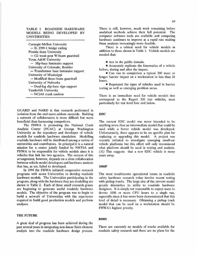
TABLE 2 ROADSIDE HARDWARE MODELS BEING DEVELOPED BY UNIVERSITIES
Carnegie-Mellon University - IL 2399-1 bridge railing
Florida State University - G2 weak-post W-beam guardrail
Texas A&M University - Slip-base luminaire support
University of Colorado, Boulder - Transformer base luminaire support
University of Mississippi -:- Modified three-beam guardrail
University of Nebraska - Dual-leg slip-base sign support
Vanderbilt University - NCIAS crash cushion
GUARD and NARD is that research performed in isolation from the end-users seldom succeeds. Building a network of collaborators is more difficult but more beneficial than harnessing competitors.
The FHWA is promoting the National Crash Analysis Center (NCAC) at George Washington University as the repository and developer of vehicle models for roadside hardware simulation. Modelling roadside hardware will be distributed among a variety of universities and contributors. In principal it is a natural mission for a center jointly funded by NHTSA and FHW A to be responsible for vehicle models since it is vehicles that link the two agencies. The success of this arrangement, however, depends on a close collaboration between vehicle model developers and hardware analysts that has, as yet, failed to developed.
In 1994 the FHW A initiated cooperative research programs with seven Universities to develop roadside hardware models. The Universities participating in the program, along with the hardware they are modelling are shown in Table 2. Each of these small research grants are beginning to generate useful roadside hardware models. The objective of the program was to begin to build a network of Universities with the experience required to build good production models and perform analyses.
THE FUTURE
A great deal of progress has been achieved during the past several years in integrating non-linear finite element analysis into the roadside hardware design process.
69
There is still, however, much work remaining before analytical methods achieve their full potential. The computer software tools are available and computing hardware continues to improve at a rapid rate making these analyses increasingly more feasible.
There is a critical need for vehicle models in addition to those shown in Table 1. Vehicle models are needed that:
• Are in the public domain. • Accurately replicate the kinematics of a vehicle
before, during and after the impact. • Can run to completion a typical 200 msec or
longer barrier impact on a workstation in less than 24 hours.
• Represent the types of vehicles used in barrier testing as well as emerging problem areas.
There is an immediate need for vehicle models that correspond to the Report 350 test vehicles, most particularly for test level four and below.
820C
The current 820C model was never intended to be anything more than an intermediate model that could be used while a better vehicle model was developed. Unfortunately, there appears to be no specific plan for replacing or upgrading this model. A project was recently initiated to investigate emerging small-car vehicle platforms but this effort will only recommend what platform should be used in testing and analysis. (31) This suggests that a new 820C vehicle is many years away.
2000P
The most troublesome operational issues in roadside safety hardware research today involve recent testing with pickup trucks. The large size of the current model greatly diminishes its utility to roadside hardware designers. It is simply not reasonable to expect users to devote 1000 or more CPU hours to a single run, especially since it has never been demonstrated that this level of detail is necessary. Obtaining a pickup truck model that can be used on a workstation should be FHW A's highest priority.
sooos
There are currently no models of trucks available for roadside safety research and there are no plans for the

iiiil --
70
development of such models. The 8000S is a key vehicle (' 1 • 1 ~' 4 • • • • • 1 1 " 1 LUI Ul iu15<:; 1 au t<:;i!ti1115 1'111\;<:; '""' l<:;VCI lUUl \;Ul l CS)JUllUI>
roughly to AASHTO PL-2. There will be a need for other types of vehicles as
well in the coming years: minivans, sport utility vehicles, and cab-forward vehicles to name just several. At some point the roadside hardware community must determine what types of models are required to evaluate the performance of roadside appurtenances. The development of vehicle models has been expensive and time consuming. Given the vehicle model, developing and using barrier models can be done by a variety of Universities and research contractors. The government must, however, take the lead in developing and maintaining vehicle models in the public domain that can be used by roadside hardware researchers.
At this early stage it is vital that the FHW A concentrate its scarce resources on producing practical results that help address pressing operational questions: the performance of pickup trucks on common guardrails and terminals, the performance of mini-vans in hardware impacts, the effect of non-standard impact conditions on vehicle kinematics and many more. If finite element analysis is not part of the solution to these current problems, the simulation community will have missed a rare opportunity to prove the utility of analytical methods.
The use of finite element analysis has great potential for improving roadside hardware designs. Transforming this potential into action, however, requires leadership and a clear vision of how finite element analysis fits into the overall roadside safety program.
REFERENCES
1. D. W. Harwood, J. M. Mason, and J. L. Graham, Conceptual Plan for an Interactive Highway Safety Design Model, Report FHWA-RD-93-122, Federal Highway Administration, Washington. D.C.. 1994.
2. Cornell Aeronautical Laboratory, "Development of an Analytical Approach to Highway Barrier Design and evaluation," Research Report 65-2, New York Department of Public Works, April, 1963.
3. G. W. McAlpin, M.D. Graham, W. C. Burnett and R. R. McHenry, "Development of an Analytical Procedure for Prediction of Highway Barrier Performance," In Geometric Design and barrier Rails, Highway Research Record Number 83, Highway Research Board, Washington, D.C., 1963.
4. M. D. Graham, W. C. Burnett, J. L. Gibson, and R. H. Freer, "New Highway Barriers: The Practical Application of Theoretical Design," Highway
Research Record 174, Highway Research Board, -vVasningtun, v.C., i'.16/.
5. R.R. McHenry and N. J. DeLeys, Development of Analytical Aids to Minimization of Single Vehicle Accidents, Cornell Aeronautical Laboratory, Report VJ-2251-V-10, 1971.
6. D. J. Segal, Highway-Vehicle-Object Simulation Model - 1976, Report FHWA-RD-163, Federal Highway Administration, Washington, D.C., 1976.
7. G. H. Powell, BarrierVII: A Computer Program for Evaluation of Automobile Barrier Systems , Report FHWA-RD 76-162, Federal Highway Administratioll, Washington, D.C., 1973.
8. R. E. Welch and E. Pang, Validation and Application of the Guard Computer Program, Unpublished report for project DOT-FH-11-9460, Chipetta, Welch and Associates, Palos Hills, IL, 1984.
9. N. W. Iwankiw et al, Modeling the Interaction of Heavy Vehicles with Protective Barriers, IIT Research Institute, March 1980.
10. S. Basu and G. ~.1cHalc, Numerical Analysis of Roadside Design (NARD), Report FHWA-RD-88-212, Federal Highway Administration, Washington, D.C., 1988.
11. H. Kami!, D. S. Logie and M. H. Ray, "Development of a Plan for Upgrading VehicleBarrier Response Simulation Capabilities," Unpublished report for FHWA (SAT 280.03), Structural Analysis Technologies, Inc. 4677 Old Ironsides Drive, Santa Clara, CA 95054, April 1992.
12. R. L. Chiapetta, Development of an Upgrading Plan for Highway Safety Simulation Models, Report FHWA-RD-92-078, Federal Highway Administration, Washington, D.C., September 1992.
13. M. Mcculough, An Upgrade Plan for FHWA Roadway Safety Simulation Models, Report FHWARD-93-189, Federal Highway Administration, Washington, D.C., 1994.
14. R. G. Whirley, B. E. Engelmann, DYNA3D: A l\lru11i11onr 1fynJ;rit T11,.oo_rlin1nneoir.nnl J:i'j,,.;fn i;7,,,,.,.,,11f . ...................... .--..... I" .... .., .... ...._ .... ...,..., -··· •v••u•....,•• .... • .a "'""""' ......., ...... ,,."''""
Code for Solid and Structural Mechanics - User's Manual, Report UCRL-MA-107254 Revision 1, Lawrence Livermore National Laboratory, Livermore, CA, November, 1993.
15. NHTSA, Traffic Safety Facts 1992, Report Number DOT-HS-808-022, National Highway Traffic Safety Administration, Washington, D.C., March 1994.
16. H. E. Ross, Jr., White paper on !STEA vehicles, Texas Transportation Institute, College Station, TX, 1995.
17. H. E. Ross, Jr., D. L. Sicking, R. A. Zimmer and J. D. Michie, Recommended Procedures for the Safety Perfomw11ce Evuluution of Highway Features ,

National Cooperative Highway Research Program, Report 350, Transportation Research Board, Washington, D.C., 1993.
18. L. A. Troxel, M. H. Ray and J. F. Carney, III, Accident Data Analysis of Side-Impact Fixed-Object Collisions, Report Number FHWA-RD-91-122, Federal Highway Administration, Washington, D.C., 1994.
19. M. H. Ray and J. F. Carney, Side Impact Crash Testing of Roadside Strnctures, Report Number FHWA-RD-92-079, Federal Highway Administration, Washington, D.C. 1993.
20. K. K. Mak and W. C. Menges, Testing of State Roadside Safety Systems, Texas Transportation Institute, Federal Highway Administration Project DTFH61-89-C-00089, in-progress.
21. C. F. Brown, FOIL Test 94F032, Draft of unpublished test report, Federal Outdoor Impact Laboratory, Federal Highway Administration, Washington, D.C., 1994.
22. M. H. Ray and J. R. Viner, "Importance of Vehicle Structure and Geometry on the Performance of Roadside Hardware Safety Features", In Vehicle Highway Infrastrncture: Safety Compatibility, Report P-194, Society of Automotive Engineers, Warrendale, PA, 1987.
23. J. W. Wekezer, M. S. Oskard, R. W. Logan and E. Zywicz, "Vehicle Impact Simulation" in Journal of Transportation Engineering, Vol. 199 No. 4, American Society of Civil Engineers, New York, N.Y., July/August, 1993.
24. A. S. Lee, "Debug frontal 1983 Honda Civic Ingrid Model received from EASi," Report on Task D.1 of the FHW A-NHTSA-LLNLCooperativeAgreement,
71
Lawrence Livermore National Laboratory, Livermore, CA, June 10, 1994.
25. E. Cofie and M. H. Ray, Finite Element Model of a Small Automobile Impacting a Rigid Pole, Report FHWA-RD-94-151, Federal Highway Administration, Washington, D.C. 1995.
26. S. Varadappa, S. C. Shyo, A. Mani, Development of a Passenger Vehicle Finite Element Model, Report DOT-HS-808-145, National Highway Traffic Safety Administration, Washington, D.C., November, 1993.
27. G. J. Kay, "Impact Simulation Experience Using NHTSA Developed Vehicle Models," Task Report for the FHWA-NHTSA-LLNL Cooperative Agreement, Lawrence Livermore National Laboratory, Livermore, CA, January 22, 1995.
28. A. S. Lee, "Validated frontal LLNL modified Honda Civic Ingrid model for three rigid pole and U-channel sign post impact simulations", Task Report on Task D.2 of the FHWA-NHTSA-LLNL Cooperative Agreement, Lawrence Livermore National Laboratory, Livermore, CA, June 10, 1994.
29. M. H. Ray, "Using Finite Element Analysis in Designing Roadside Hardware," in Public Roads, Vol. 57, No. 4, Federal Highway Administration, Washington, D.C., Spring, 1994.
30. J. Reid and D. L. Sicking, "Reevaluation of Turned Down Guardrail Terminals," Transportation Research Record (in progress), Transportation Research Board, 1995.
31. R. Bligh and K. K. Mak, "Assessment of Motor Vehicle Characteristics," on-going FHWA Contract DTFH61-94-C-00152, Texas Transportation Institute, 1995.