use of eps as a lightweight fill material -...
TRANSCRIPT
Page 1 of 20
Use of EPS as a Lightweight Fill Material
on the Port Mann / Highway 1 Improvement Project,
Vancouver to Langley, BC
Marek Buksowicz, P.Eng.
Stuart Culpan, P.Eng.
Paper prepared for presentation
at the Structures Session
of the 2014 Conference of the
Transportation Association of Canada
Montreal, Quebec

Page 2 of 20
ABSTRACT
As part of the design-build Port Mann / Highway 1 (PMH1) Improvement Project, 25 lightweight bridge embankments were designed and constructed using expanded polystyrene (EPS) foam. EPS embankments are typically used as an alternative to mineral fill embankments where the ground is soft and would require lengthy preloading to control post-construction settlements. This has made EPS embankments particularly attractive for design-build projects, where construction schedules are typically compressed and traditional methods of ground improvement are much less attractive. This paper provides three case studies that highlight the design features developed to address the unique characteristics of these sites. In the Burnaby Lake area in Burnaby, pile-supported EPS embankments replaced multiple bridge spans. At King Edward Street in Coquitlam, the rapid constructability of EPS embankments enabled a long curved bridge to be replaced by a much shorter straight bridge. At the 202nd Street Overpasses in Langley, ground liquefaction and slope stability challenges were overcome by using EPS embankments. In addition, several other applications of EPS used on the PMH1 Project are discussed. 1 INTRODUCTION The design-build Port Mann / Highway 1 (PMH1) Improvement Project is a five-year, $2.4-billion upgrade to Trans-Canada Highway 1 and associated transportation infrastructure between Vancouver and Langley in British Columbia, Canada. With full completion slated for late 2014, the PMH1 Project encompasses a 37 km portion of the Trans-Canada Highway corridor from the McGill Interchange in Vancouver to 208th Street in Langley. Hatch Mott MacDonald (HMM) and MMM Group led the design of all onshore works, including the structural design of 45 bridges, 52 retaining walls, and 25 expanded polystyrene (EPS) embankments. Further overview of the PMH1 Project is presented in the “Port Mann / Highway 1 Improvement Project: Description and Overview” paper by Buksowicz et al. (2014).
Marek Buksowicz was the Structures Design Manager responsible for delivery of all onshore structures including bridges, retaining walls, EPS embankments, culverts, and other miscellaneous elements. Stuart Culpan was the EPS Design Lead responsible for the design and delivery of all EPS embankments.
2 PMH1 PROJECT
2.1 Project Objectives
The PMH1 Project is part of the Gateway Program established by the Province of British Columbia in response to regional growth pressures resulting in traffic congestion. The original Port Mann Bridge crossing the Fraser River and adjoining sections of Highway 1 were built in the early 1960s when Metro Vancouver’s population numbered approximately 800,000 residents. Prior to the PMH1 Project improvements, this infrastructure served a population of over 2.4 million residents, a number expected to increase by a further 1.0 million over the next 20 years. Congestion on the original highway resulted in increased travel times with corresponding impacts on regional and national trade and the efficient movement of goods and people. The decision was made to improve this transportation corridor to
• Address congestion and reduce travel times;
• Improve the movement of goods, people, and trade;
• Improve connections between communities;
• Enhance transit service along the Highway 1 corridor and enhance inter-modal connectivity;
• Expand the high-occupancy vehicle (HOV) lanes and improve the cycling and pedestrian networks;
• Improve safety for vehicle operators, passengers, cyclist and pedestrians; and,
• Improve the seismic resilience of the transportation infrastructure.
2.2 Project Description
The Project has been divided into two principle components: 1) the offshore works comprising the new Port Mann Bridge over the Fraser River and associated approach viaducts (total length 2.0 km), and 2), the onshore works comprising all other infrastructure work within the 37-km Highway 1 corridor on either side of the Port

Page 3 of 20
Mann Bridge. This paper focuses on the onshore components of the Project and specifically, the use of lightweight EPS fill in addressing the challenges of building new and widening existing infrastructure at locations where conventional methods using mineral fill did not suit the poor ground conditions.
The PMH1 Project is the largest transportation infrastructure upgrade in British Columbia’s history and also one of the largest infrastructure projects in Canada. Once completed, it will address the project objectives by improving the highway from McGill Street in Vancouver to 208th Street in Langley, and resulting in travel time reductions of up to 30% and saving drivers up to one hour per day. Figure 1 shows the extent of the Project. The highway widening comprises one continuous HOV lane in each direction extending from Grandview Highway in Vancouver to 208th Street in Langley, and one additional general-purpose lane from McGill Street in Vancouver to 200th Street in Langley. Between Brunette Avenue in Coquitlam and 152nd Street in Surrey, a combination of local and through movements has increased traffic volumes, requiring additional general-purpose and collector / distributor lanes.
Figure 1 - PMH1 Location Plan
Improvements to 176th Street and the Fraser Heights Connector provide connections between Highway 1 and the South Fraser Perimeter Road (Highway 17), forming a new direct route to Deltaport and the Tsawwassen Ferry Terminal. Provision has also been made for a future connection to the Golden Ears Bridge by an extension of 96th Avenue. The 202nd Street Park-n-Ride facility was added to the project scope to provide a new transit exchange facility with an express bus connection between Langley and the Vancouver SkyTrain network at Lougheed Town Centre Station in Burnaby.
2.3 Project Geology
The PMH1 Project corridor has many unique geological features that necessitated the use of lightweight fill. EPS was selected because it was the most appropriate alternative solution to building conventional mineral fill embankments and was best suited to satisfy the long-term performance requirements of the Project. The project corridor traverses a wide variety of ground conditions, reflecting many of the unique geotechnical features of the Metro Vancouver area. The highway crosses sedimentary rock, ice age glacial deposits of the “uplands” and the highly variable marine and deltaic sediments of the “lowlands.” The highway was
Page 4 of 20
constructed in the 1960s and the alignment was deliberately situated in areas with challenging ground conditions to leave the adjacent, less-challenging ground for commercial and residential development. As a result, many interchanges were situated in localized basins of soft, compressible, or liquefiable soils. In the original construction, woodwaste (also referred to as hog fuel) was used extensively as a lightweight fill. Due to environmental restrictions, this material has now been precluded from use. Alternative design solutions were required that addressed the differential settlement risks associated with parts of the alignment being previously loaded and others not. The Burnaby Lake area in the West Segment comprised 10 to 15-m-deep marine sediments comprising normally consolidated clays with variable sensitivity overlying till-like soils. Due to their compressibility, extensive preloading and surcharging would have been necessary to control post-construction settlements. In some areas, the marine sediments are highly sensitive to disturbance and would give rise to major construction and stability challenges. In the fast-track environment of design-build, alternative solutions with less construction risk were developed to address the project needs. The Cape Horn area of the Central Segment comprised soft compressible deltaic sediments, including loose to compact sand, overbank silt, organic silt, and peat overlying till-like soils. Typically, the near-surface ground water levels and deposit thickness meant it was not practical to remove and replace these soils. The deltaic sediments were normally consolidated to lightly over-consolidated, and any solutions requiring preloading and surcharge required careful construction staging for lengthy periods of time. In the fast-tracked environment of design-build, neither of these options was considered appropriate and alternative design solutions, such as the use of EPS, were developed to meet the project needs. In the East Segment, ground conditions were more favourable, comprising glacial deposits overlying till-like soils. At the 202nd Street Interchange in Langley, however, soft clays below a surface crust required careful treatment to accommodate the 3 to 4 m elevation increase necessary for the new grade separation. The project corridor is located in an area of high seismicity and the design requirements included multi-level earthquake performance requirements, such as provision for immediate service, limited access, repairable damage, and no collapse. The design requirements applied to bridges, retaining walls, and EPS embankments. In the Cape Horn area, the sediments were assessed to be potentially liquefiable up to a depth of 25 m and could result in post-seismic settlements and lateral ground spread, affecting elements of the new infrastructure. This resulted in the need for extensive ground improvements, including stone columns, compaction piles, wick drains, and jet grouting. In conjunction with these measures, lightweight EPS fill was also used to expand the highway infrastructure and reduce the driving forces associated with seismic instability.
3 EPS
3.1 Introduction
EPS (also known as “geofoam”) has been used in road projects for over 40 years; its use has been growing rapidly in recent years with the increase in design-build projects and their associated compressed construction schedules. EPS provides a viable alternative to lengthy preloading of soft soils for control of settlements and widening of embankments to achieve settlement compatibility. As part of the PMH1 Project, 25 lightweight bridge approach embankments were designed and constructed using EPS. In addition, EPS was used successfully in several other applications, including utility protections and temporary detours.
Page 5 of 20
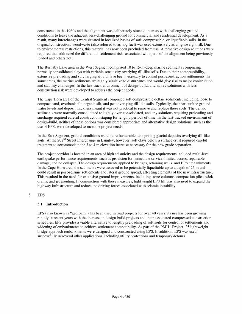
Figure 2 – EPS Embankment Under Construction
3.2 Project Applications
As described above, significant portions of the highway corridor are founded on load-sensitive and liquefiable soils. EPS was selected as a lightweight fill solution to address the following site-specific challenges:
1. Where the ground conditions were too weak to support a mineral fill embankment, EPS was used as an alternative to building a structural viaduct. In several locations the EPS embankments proved a more viable, cost-effective alternative to the viaduct and significantly reduced the bridge length.
2. Where there was insufficient time to adequately preload and surcharge the ground, EPS was used instead of a mineral fill embankment to reduce settlements. The ground conditions were such that preloading / surcharging requirements would be required for an extended period, incompatible with the fast-track project schedule.
3. Where a mineral fill embankment could cause slope failures under the design level earthquake, EPS was used to provide an embankment with minimal additional mass, thus reducing the driving mechanisms causing seismic instability.
4. Many elements of the PMH1 Project (bridges, embankments etc.) required staged construction within the constrained corridor available for highway expansion. EPS is a self-supporting material well suited to staged construction where vertical seams between sections can be readily provided.
5. Where the highway widening affected existing buried utility crossings, EPS proved to be an effective load compensation material to protect existing utilities in poor soils from ground movements resulting from raising or widening existing embankments using conventional fill materials.
6. In areas of poor ground, the contractor elected to use EPS fill for some temporary detour embankments to allow fast construction and to reduce the amount of pavement operation and maintenance that would otherwise be necessary using conventional mineral fills.
3.3 Material Characteristics
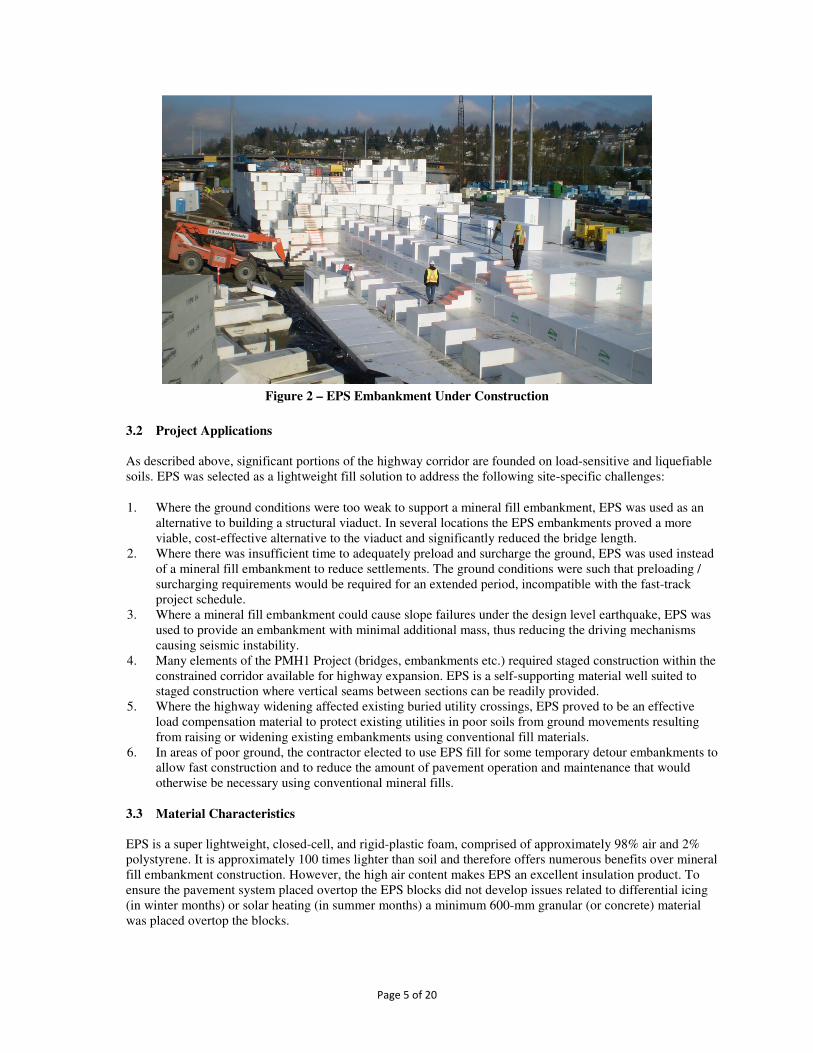
EPS is a super lightweight, closed-cell, and rigid-plastic foam, comprised of approximately 98% air and 2% polystyrene. It is approximately 100 times lighter than soil and therefore offers numerous benefits over mineral fill embankment construction. However, the high air content makes EPS an excellent insulation product. To ensure the pavement system placed overtop the EPS blocks did not develop issues related to differential icing (in winter months) or solar heating (in summer months) a minimum 600-mm granular (or concrete) material was placed overtop the blocks.

Page 6 of 20
The main parameter used to differentiate grades of EPS is density; both the strength and cost of EPS is directly proportional to its density. For the design of EPS blocks, the imposed dead and live load bearing pressures were kept below the 1% elastic strain limit. All EPS blocks on the PMH1 Project were manufactured in accordance with ASTM D6817, “Standard Specification for Rigid Cellular Polystyrene Geofoam” and tested in accordance with ASTM D1621, “Standard Test Method for Compressive Properties of Rigid Cellular Plastics.”
Figure 3 – Placement of Blocks at Kensington Avenue EPS Embankment
3.4 Material Vulnerabilities
Hydrocarbons One of the major durability considerations for EPS used in highway construction is that liquid petroleum hydrocarbons, such as gasoline and diesel fuel, will dissolve EPS. To protect the blocks from a potential fuel spill, they were fully encapsulated with a 20-mil-thick (0.5 mm) textured polyethylene geomembrane on the top to provide adequate friction at the pavement / EPS interface to limit sliding during a seismic event, and a plain 10-mil-thick (0.25 mm) polyethylene sheet on the sides. The EPS blocks were protected from any in-situ soils that contained hydrocarbons by excavating and disposing of any existing material that contained asphalt. A 200-mm-thick sand levelling course was provided below the blocks, which also served as a separation layer from any latent hydrocarbons that may have been present in the existing sub-soils and old, abandoned asphalt pavement. Fire (Sources of Combustion) EPS is a highly combustible material and should not be exposed to open flame or ignition sources. This was of particular concern during construction when the EPS could potentially be exposed to site activities such as welding. In the finished state, the EPS blocks were protected from fire damage via the concrete facing panels that were designed to achieve the 2-hour fire rating as required by the Design-Build Agreement (DBA). Physical Damage The EPS blocks were protected from physical damage on the top and sides of the embankment by the pavement system and the facing panels respectively. To prevent damage to the EPS blocks during construction, it was necessary to impose weight restrictions on construction vehicles.
Page 7 of 20
Durability EPS is an inert material; EPS is not biodegradable and does not dissolve or breakdown when in the ground or when exposed to ground water. Furthermore, it is not a known food source for any living organism, nor have there been any reported cases of insect damage to EPS blocks used in embankment construction. Ultraviolet radiation from sunlight can turn the EPS blocks a yellow colour and create a thin chalky residue on the outer surface of the blocks. Although the residue does not affect the structural integrity of the block itself, it can reduce shear friction at the interface between blocks. For embankments located in zones of high seismicity, as was the case for the PMH1 Project, where interface friction was critical, exposure to sunlight during construction was limited to avoid degradation. Buoyancy
Given the super lightweight nature of EPS, the material is highly susceptible to floatation. The PMH1 Project’s embankments were ballasted against buoyancy by the 1.2-m-nominal-thick pavement system. They were designed with a factor of safety of 1.2 against floatation in accordance with NCHRP Report 529. At some embankment locations, the design flood level dictated the EPS founding elevations and alternate lightweight fill materials, such as pumice, were used in conjunction with EPS to overcome buoyancy concerns.
4 DESIGN CONSIDERATIONS
4.1 Design Codes / Guidelines
The primary reference for design of the EPS embankments was the PMH1 Design-Build Agreement (DBA). This document outlined the minimum design requirements and the material specification for the EPS blocks. Design of the EPS embankments was based on NCHRP Report 529, “Guidelines and Recommended Standard for Geofoam Applications in Highway Embankments.” Design of the structural components of the embankments, e.g., facing panels, slabs, barriers etc., was carried out in accordance with the Canadian Highway Bridge Design Code CAN/CSA-S6-06 and CSA A23.3, “Design of Concrete Structures.” An internal document, “EPS Embankment Design Guidelines” was prepared for use by the project design team. This document collated the applicable requirements of the DBA, summarized additional design references and provided guidance to the project engineers to ensure consistency in the design of all EPS embankments. 4.2 Geometry and Layout
Each EPS embankment was custom designed to match the specific roadway alignment and profile; as such, no two embankments had the same geometry. They varied in width from 10 to 60 m, in length from 35 to 270 m, and in height up to 15 m. The “typical” PMH1 embankment was 12 m wide, 100 m long, and 11 m high at the bridge end, tapering to grade at the low end (see Figure 4). The typical dimensions of an EPS block used on the PMH1 Project were 1.2 m wide x 0.9 m high x 2.4 m long, and the blocks were assembled in staggered alternating rows to avoid continuous seams between layers. This arrangement ensured the blocks formed a uniform, homogenous mass for even distribution of vertical load and also for resistance to interlayer sliding under earthquake loading. The EPS founding elevation was typically governed by the requirement to minimize long-term embankment settlement or to ensure global stability under earthquake loading. As a result, the total design bearing pressure exerted by the embankment was limited to approximately 25 kPa. In some locations, the 1:200-year return flood elevation dictated the embankment design and, in order to prevent buoyancy, the EPS blocks were placed above the flood-critical elevation.

Page 8 of 20
Figure 4 – Typical EPS Embankment Cross-Section
In all embankment locations, the EPS volume was optimized to ensure the most cost-effective construction solution. However, in some locations, unfavourable height-to-width aspect ratios resulted from the highway alignment or the embankment’s proximity to adjacent structures. Where possible, the EPS embankments were widened in order to resist seismic overturning forces and, where acute corners were present, the embankments were widened to prevent overstressing the blocks.
4.3 Geotechnical
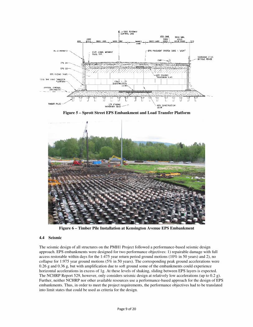
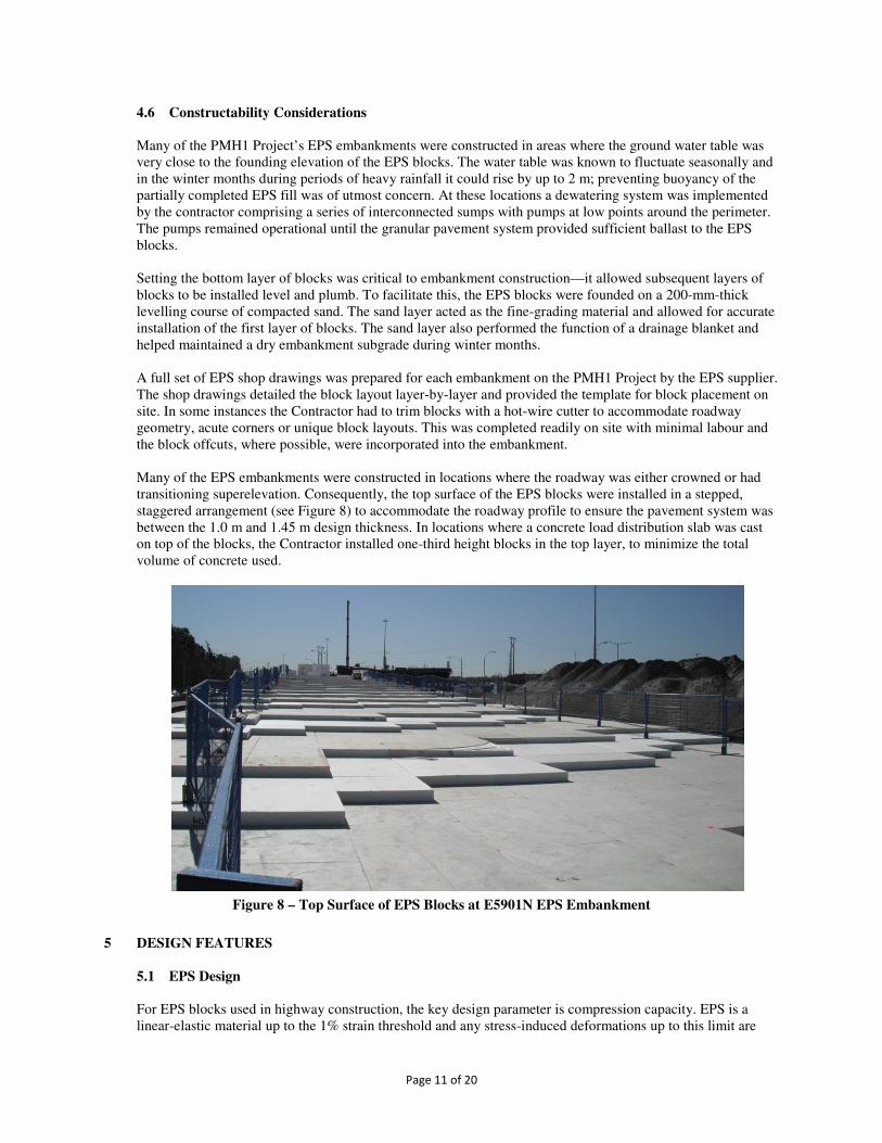
Geotechnical considerations were key to the design of each EPS application, and the design team worked closely with the geotechnical specialists to understand the characteristics of each site and also the Contractor to understand the staging and schedule requirements. In general, control of long-term post construction settlements was the main criteria to be satisfied. Where conditions necessitated, a “zero net load” approach was adopted by offsetting the weight of the pavement structure with a corresponding amount of sub-excavation. In some locations, this was quite challenging and required more sophisticated details using pumice lightweight backfill under the main volume of EPS. In the West Segment, buoyancy issues caused by high water tables and flood elevations precluded the use of sub-excavation with grade-supported EPS. The unique solution developed comprised a granular load transfer platform where a closely spaced grid of piles extending to the till-like layer supported a granular, geogrid-reinforced load transfer platform (LTP). Two variants were developed: timber piles at 1.5 m centres supporting a 1.2-m-thick LTP and concrete piles at 1.5 m centres supporting a 2.4-m-thick LTP. Concrete piles were preferred by the Contractor to reduce the volume of EPS. In four embankments, a total of 5,000 timber piles and 2,700 concrete piles were used; the timber piles incorporated preservative treatment for durability. The regular EPS embankment consistent with the details used elsewhere on the Project was built directly off the top of the LTP. The use of piles to support the LTP proved to be a fast and cost-effective solution over alternative ground improvement techniques, such as deep soil mixing (see Figures 5 and 6).
Page 9 of 20
Figure 5 – Sprott Street EPS Embankment and Load Transfer Platform
Figure 6 – Timber Pile Installation at Kensington Avenue EPS Embankment
4.4 Seismic
The seismic design of all structures on the PMH1 Project followed a performance-based seismic design approach. EPS embankments were designed for two performance objectives: 1) repairable damage with full access restorable within days for the 1:475 year return period ground motions (10% in 50 years) and 2), no collapse for 1:975 year ground motions (5% in 50 years). The corresponding peak ground accelerations were 0.26 g and 0.36 g, but with amplification due to soft ground some of the embankments could experience horizontal accelerations in excess of 1g. At these levels of shaking, sliding between EPS layers is expected. The NCHRP Report 529, however, only considers seismic design at relatively low accelerations (up to 0.2 g). Further, neither NCHRP nor other available resources use a performance-based approach for the design of EPS embankments. Thus, in order to meet the project requirements, the performance objectives had to be translated into limit states that could be used as criteria for the design.

Page 10 of 20
As described in “Performance Based Design of EPS Embankments in Regions of High Seismicity” paper by Gérin (2013), the repairable damage objective was defined as less than 50 mm of sliding between embankment layers and the no collapse objective was defined as less than 400 mm of sliding. Accompanying analysis and design methods were also developed from first principles. In particular, a non-linear analysis method to evaluate internal sliding was developed using the Newmark sliding block approach taking into account the stiffness of the embankment itself.
The seismic analysis indicated that the critical surface for internal sliding was between the goemembrane and the EPS blocks or between the geomembrane and the granular pavement structure. To limit sliding and satisfy the performance objectives, a minimum coefficient of friction of 0.6 was required. The coefficient of friction between a smooth membrane and EPS ranges from 0.1 to 0.3; therefore, a geomembrane with a rough surface on both sides was specified for the top surface of all EPS embankments. The sides were covered with lower cost smooth polyethylene sheeting. 4.5 Staged Construction
In several locations on the Project there were extremely tight property constraints. This was especially evident in locations where bridges and embankments were replacing existing structures, and where the new road configuration overlapped with the existing. At these sites there was insufficient space to build the entire EPS embankment in one stage and, in order to maintain traffic movements within the property boundaries, the embankments had to be constructed in two stages. The first stage of construction involved building half the EPS embankment adjacent to the bridge structure. Traffic was then transferred onto the half-embankment and the existing bridge was demolished. The second stage of construction involved building the remaining half of the embankment. Figure 7 shows the configuration after the first stage of construction at Sprott Street. This approach resulted in a full-height vertical seam in the EPS blocks at the junction between the two stages. Proper block interlock could not be achieved and, if left untreated, would result in cracks propagating up through the pavement system. To cover the vertical seam in the EPS blocks and ensure even load distribution into the underlying blocks, a 3.0-m-wide concrete slab was cast into the pavement system. To ensure structural continuity of the load transfer platform, a 6.5-m-wide concrete slab was cast integral with the LTP.
Figure 7 – Staged Construction Detail at Sprott Street EPS Embankment
Page 11 of 20
4.6 Constructability Considerations
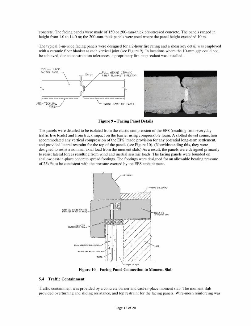
Many of the PMH1 Project’s EPS embankments were constructed in areas where the ground water table was very close to the founding elevation of the EPS blocks. The water table was known to fluctuate seasonally and in the winter months during periods of heavy rainfall it could rise by up to 2 m; preventing buoyancy of the partially completed EPS fill was of utmost concern. At these locations a dewatering system was implemented by the contractor comprising a series of interconnected sumps with pumps at low points around the perimeter. The pumps remained operational until the granular pavement system provided sufficient ballast to the EPS blocks. Setting the bottom layer of blocks was critical to embankment construction—it allowed subsequent layers of blocks to be installed level and plumb. To facilitate this, the EPS blocks were founded on a 200-mm-thick levelling course of compacted sand. The sand layer acted as the fine-grading material and allowed for accurate installation of the first layer of blocks. The sand layer also performed the function of a drainage blanket and helped maintained a dry embankment subgrade during winter months. A full set of EPS shop drawings was prepared for each embankment on the PMH1 Project by the EPS supplier. The shop drawings detailed the block layout layer-by-layer and provided the template for block placement on site. In some instances the Contractor had to trim blocks with a hot-wire cutter to accommodate roadway geometry, acute corners or unique block layouts. This was completed readily on site with minimal labour and the block offcuts, where possible, were incorporated into the embankment. Many of the EPS embankments were constructed in locations where the roadway was either crowned or had transitioning superelevation. Consequently, the top surface of the EPS blocks were installed in a stepped, staggered arrangement (see Figure 8) to accommodate the roadway profile to ensure the pavement system was between the 1.0 m and 1.45 m design thickness. In locations where a concrete load distribution slab was cast on top of the blocks, the Contractor installed one-third height blocks in the top layer, to minimize the total volume of concrete used.
Figure 8 – Top Surface of EPS Blocks at E5901N EPS Embankment
5 DESIGN FEATURES
5.1 EPS Design
For EPS blocks used in highway construction, the key design parameter is compression capacity. EPS is a linear-elastic material up to the 1% strain threshold and any stress-induced deformations up to this limit are

Page 12 of 20
recoverable. However, above 1% strain, EPS is potentially susceptible to creep deformation caused by permanent damage to the cell structure. The allowable compressive resistance by EPS grade used in design are presented in Table 1. In accordance with NCHRP Report 529 recommendations, EPS bearing pressures for dead and live load design were kept below the 1% strain limit. Design of the EPS blocks was carried out using unfactored applied loads and a material safety factor of 1.2—similar to an allowable stress design approach. The core of the PMH1 Project’s EPS embankments comprised EPS 22 (the minimum strength stipulated by the DBA). The top 1.0 m comprised EPS 24, where the effect of concentrated wheel loads was highest. EPS 29 was used locally to support the bridge approach slab and EPS 39 was used in locations where the blocks were subjected to higher loading conditions.
Table 1 – EPS Material Properties
Material Property Units EPS 22 EPS 24 EPS 29 EPS 39
Density kg/m
3
(pcf)
21.6
(1.35)
23.7
(1.50)
28.8
(1.80)
38.4
(2.40)
Compression Resistance
(at 1% Strain)
kPa
(psi)
50
(7.3)
65
(9.4)
75
(10.9)
103
(15.0)
Compressive Resistance
(at 5% Strain)
kPa
(psi)
115
(16.7)
140
(20.0)
170
(25.0)
241
(35.0)
5.2 Pavement Options
The objective of the EPS pavement was to provide a durable system capable of resisting long term traffic load-cycles and to ensure sufficient load dispersion of truck wheel/axle forces in order to prevent overstressing the underlying EPS blocks. The EPS pavement system comprises all material placed overtop the EPS blocks, including asphalt pavement, road gravels and concrete. The minimum required thickness was 1.0 m (per the DBA) and the maximum was 1.45 m to prevent overstressing the EPS blocks and to limit the overall bearing pressure exerted by the embankment. Under both seismic loading and buoyancy forces the embankments had adequate factors of safety to resist overturning and uplift. There were three different EPS pavement systems used on the PMH1 Project:
• Type 1 - 460 or 550-mm-thick asphalt pavement (dependant on truck volumes) and 500-mm-nominal-thick road gravels
• Type 2 – 150-mm-thick asphalt pavement, 600-mm-thick road gravels and 250-mm-thick concrete load distribution slab (cast directly on top of the geomembrane)
• Type 3 – 100-mm-thick asphalt pavement, 250-mm-thick concrete load distribution slab and 700-mm-minimum-thick road gravels
The Type 1 system was the initial pavement design developed for the Project that was widely used in the West Segment. Elsewhere, specific constraints resulted in development of two additional pavement designs. The Type 2 concrete load distribution slab system was used predominantly in the Central Segment where the Contractor required a working platform for site access or to transport construction equipment, such as cranes. The Type 3 system was also used predominantly in the Central Segment for narrow embankments where it was more practical and cost-effective to connect the opposing concrete moment slabs in lieu of casting an entirely separate load distribution slab.
5.3 Facing Panels
The primary purpose of the panels was to protect the EPS blocks from fire and physical damage, and they incorporated an architectural textured finish to provide interest and relief from otherwise large areas of plain
Page 13 of 20
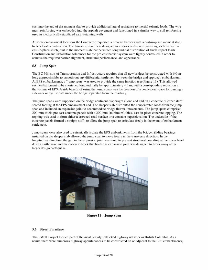
concrete. The facing panels were made of 150 or 200-mm-thick pre-stressed concrete. The panels ranged in height from 1.0 to 14.0 m; the 200-mm-thick panels were used where the panel height exceeded 10 m. The typical 3-m-wide facing panels were designed for a 2-hour fire rating and a shear key detail was employed with a ceramic fiber blanket at each vertical joint (see Figure 9). In locations where the 10-mm gap could not be achieved, due to construction tolerances, a proprietary fire-stop sealant was installed.
Figure 9 – Facing Panel Details
The panels were detailed to be isolated from the elastic compression of the EPS (resulting from everyday traffic live loads) and from truck impact on the barrier using compressible foam. A slotted dowel connection accommodated any vertical compression of the EPS, made provision for any potential long-term settlement, and provided lateral restraint for the top of the panels (see Figure 10). (Notwithstanding this, they were designed to resist a nominal axial load from the moment slab.) As a result, the panels were designed primarily to resist lateral forces resulting from wind and inertial seismic loads. The facing panels were founded on shallow cast-in-place concrete spread footings. The footings were designed for an allowable bearing pressure of 25kPa to be consistent with the pressure exerted by the EPS embankment.
Figure 10 – Facing Panel Connection to Moment Slab
5.4 Traffic Containment
Traffic containment was provided by a concrete barrier and cast-in-place moment slab. The moment slab provided overturning and sliding resistance, and top restraint for the facing panels. Wire-mesh reinforcing was
Page 14 of 20
cast into the end of the moment slab to provide additional lateral resistance to inertial seismic loads. The wire-mesh reinforcing was embedded into the asphalt pavement and functioned in a similar way to soil reinforcing used in mechanically stabilized earth retaining walls. At some embankment locations the Contractor requested a pre-cast barrier (with a cast-in-place moment slab) to accelerate construction. The barrier upstand was designed as a series of discrete 3-m-long sections with a cast-in-place stitch joint in the moment slab that permitted longitudinal distribution of truck impact loads. Construction and installation tolerances for the pre-cast barrier system were tightly controlled in order to achieve the required barrier alignment, structural performance, and appearance. 5.5 Jump Span
The BC Ministry of Transportation and Infrastructure requires that all new bridges be constructed with 6.0-m-long approach slabs to smooth out any differential settlement between the bridge and approach embankment. At EPS embankments, a “jump span” was used to provide the same function (see Figure 11). This allowed each embankment to be shortened longitudinally by approximately 4.5 m, with a corresponding reduction in the volume of EPS. A side benefit of using the jump spans was the creation of a convenient space for passing a sidewalk or cyclist path under the bridge separated from the roadway. The jump spans were supported on the bridge abutment diaphragm at one end and on a concrete “sleeper slab” spread footing at the EPS embankment end. The sleeper slab distributed the concentrated loads from the jump span and included an expansion joint to accommodate bridge thermal movements. The jump spans comprised 200-mm-thick, pre-cast concrete panels with a 200-mm-(minimum)-thick, cast-in-place concrete topping. The topping was used to form either a crowned road surface or a constant superelevation. The underside of the concrete panels formed a straight soffit to allow the jump span to articulate freely in the event of embankment settlement. Jump spans were also used to seismically isolate the EPS embankments from the bridge. Sliding bearings installed on the sleeper slab allowed the jump span to move freely in the transverse direction. In the longitudinal direction, the gap in the expansion joint was sized to prevent structural pounding at the lower level design earthquake and the concrete block that holds the expansion joint was designed to break away at the larger design earthquake.
Figure 11 – Jump Span
5.6 Street Furniture
The PMH1 Project formed part of the most heavily trafficked highway network in British Columbia. As a result, there were numerous highway appurtenances to be constructed on or adjacent to the EPS embankments,

Page 15 of 20
including guides signs, luminaires, and signals. The entire King Edward Road / United Boulevard intersection in Coquitlam, complete with traffic signals, electrical cabinets, and utility lines, was constructed on an EPS embankment. The highway appurtenances were typically pole-mounted luminaires, signals, and guide signs. The poles were accommodated by casting a concrete foundation corbel behind the barrier on the outside face of the moment slab. For large cantilevered signs, where the base reactions were significant, the concrete moment slab had to be widened into the traffic lanes to ensure there was sufficient resistance to counterbalance the reactions. Large sign bridges spanning the full width of the roadway required the moment slabs to be connected, creating a full width concrete slab.
5.7 Utility Protection
Although EPS was predominantly used on the PMH1 Project in aboveground applications, there were numerous locations where it was used in belowground applications as protection for utility pipes and as lightweight fill for ground improvement; EPS blocks were used to control long-term ground settlements. The blocks were placed in staggered alternating rows and incorporated membranes, similar to the above ground arrangement. The EPS block installations were sloped at approximately 3H:1V with the adjacent fills to ensure a smooth pavement transition. A Kinder Morgan oil pipeline and the Fortis BC high-pressure gas line were two major utilities to be protected as part of the PMH1 Project. At both locations, an aboveground EPS embankment was actually constructed overtop the utility lines and incorporated into the adjoining permanent EPS embankments.
6 SUSTAINABILITY
As indicated above, at some locations with particularly weak ground conditions, the EPS embankments reduced the length of bridge structure that would otherwise have been required. An initial whole-life assessment of the design solutions adopted indicated that for low-height EPS embankments (< 7 m), the carbon footprint is lower than the equivalent alternative bridge span solution. The EPS blocks were installed on the PMH1 Project using lightweight tools and machinery. Two people were able to install a single block and much of the EPS on the PMH1 Project was installed in this way. This reduced overall construction costs and reduced the environmental impacts of heavy earth-moving equipment typically required to build traditional mineral fill embankments. As the EPS volume was fitted to the highway geometry, many partial thickness blocks were used in the upper-most layer to keep the final average pavement thickness within the design requirements. This was typically achieved by using one-third-thickness blocks to form a stepped surface. This resulted in a large volume of partial thickness blocks; permission was granted to reuse these offcuts by gluing them together to form full dimensional blocks. These were incorporated into and distributed within the main EPS volume. Other EPS block offcuts that were too small to be reused directly in the EPS fill, were recycled and used in the fabrication of future blocks. EPS manufacturers are permitted to include up to 5% (by volume) recycled EPS in the fabrication of new blocks. Given the scale of the PMH1 Project, this was a significant benefit from a sustainability perspective. EPS was used (and reused) by the Contractor for the construction of temporary-works embankments at detour locations and as lightweight fill for temporary utility protections. Where possible, these “used” blocks were installed in the permanent-works EPS embankments. The blocks were visually inspected prior to installation and limitations were imposed on the total number and final location of the blocks within a given embankment.
Page 16 of 20
7 CASE STUDIES
7.1 Case 1 –Burnaby Lake Area: Willingdon Avenue, Sprott Street, and Kensington Avenue
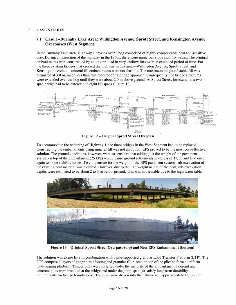
Overpasses (West Segment) In the Burnaby Lake area, Highway 1 crosses over a bog comprised of highly compressible peat and sensitive clay. During construction of the highway in the 1960s, there were numerous slope stability issues. The original embankments were constructed by adding preload in very shallow lifts over an extended period of time. For the three existing bridges that crossed the highway in this area—Willingdon Avenue, Sprott Street, and Kensington Avenue—mineral fill embankments were not feasible. The maximum height of stable fill was estimated at 3.0 m, much less than that required for a bridge approach. Consequently, the bridge structures were extended over the bog until they were about 2.0 m above ground. At Sprott Street, for example, a two-span bridge had to be extended to eight (8) spans (Figure 12).
Figure 12 – Original Sprott Street Overpass
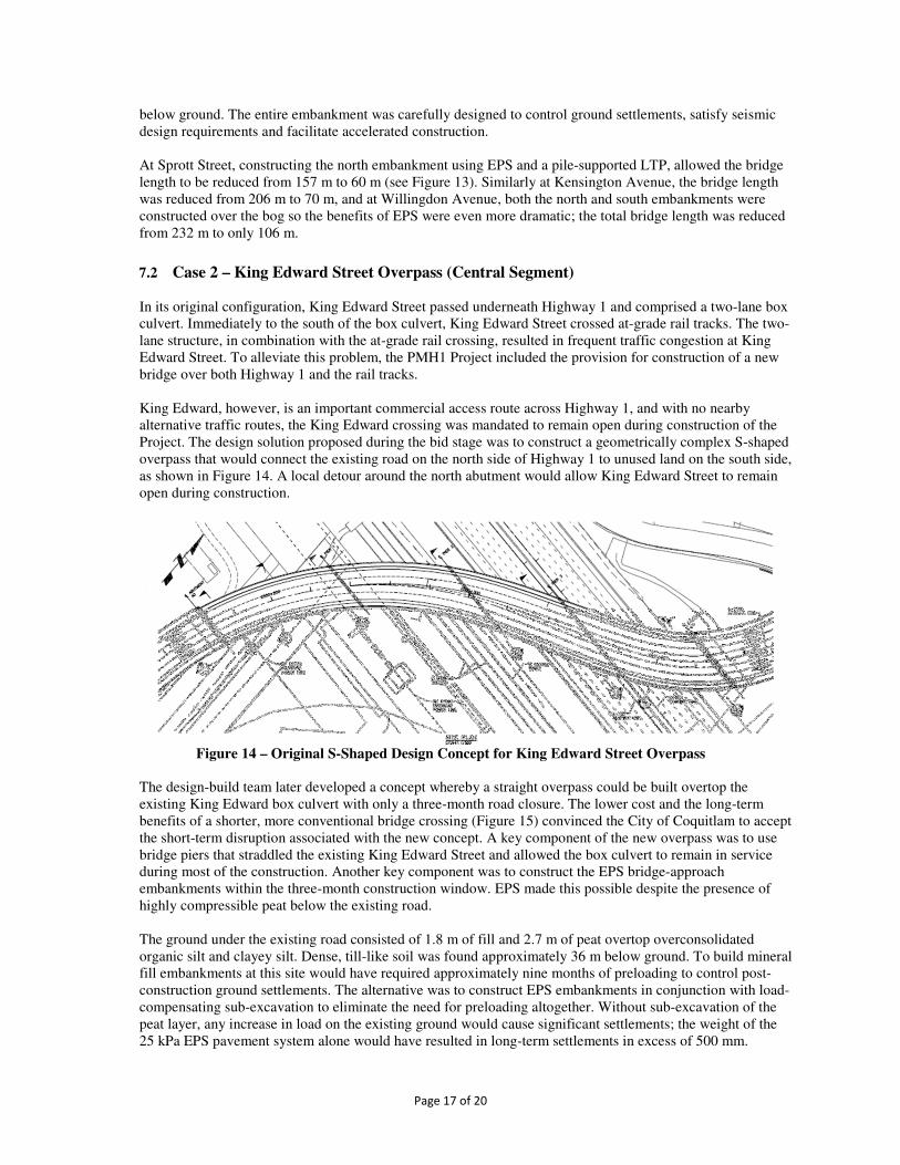
To accommodate the widening of Highway 1, the three bridges in the West Segment had to be replaced. Constructing the embankments using mineral fill was not an option; EPS proved to be the most cost-effective solution. The ground conditions, however, were so sensitive that adding just the weight of the pavement system on top of the embankment (25 kPa) would cause ground settlements in excess of 1.0 m and lead once again to slope stability issues. To compensate for the weight of the EPS pavement system, sub-excavation of the existing peat material was required. However, due to the lightweight nature of the peat, sub-excavation depths were estimated to be about 2 to 3 m below ground. This was not feasible due to the high water table.
Figure 13 – Original Sprott Street Overpass (top) and New EPS Embankment (bottom)
The solution was to use EPS in combination with a pile-supported granular Load Transfer Platform (LTP). The LTP comprised layers of geogrid reinforcing and granular fill placed on top of the piles to form a uniform load-bearing platform. Timber piles were installed under the majority of the embankment footprint and concrete piles were installed at the bridge end under the jump span (to satisfy long-term durability requirements for bridge foundations). The piles were driven into the till-like soil approximately 15 to 20 m
Page 17 of 20
below ground. The entire embankment was carefully designed to control ground settlements, satisfy seismic design requirements and facilitate accelerated construction. At Sprott Street, constructing the north embankment using EPS and a pile-supported LTP, allowed the bridge length to be reduced from 157 m to 60 m (see Figure 13). Similarly at Kensington Avenue, the bridge length was reduced from 206 m to 70 m, and at Willingdon Avenue, both the north and south embankments were constructed over the bog so the benefits of EPS were even more dramatic; the total bridge length was reduced from 232 m to only 106 m.
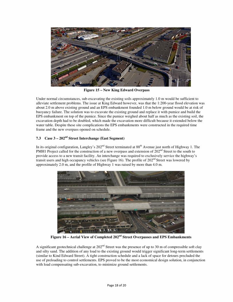
7.2 Case 2 – King Edward Street Overpass (Central Segment) In its original configuration, King Edward Street passed underneath Highway 1 and comprised a two-lane box culvert. Immediately to the south of the box culvert, King Edward Street crossed at-grade rail tracks. The two-lane structure, in combination with the at-grade rail crossing, resulted in frequent traffic congestion at King Edward Street. To alleviate this problem, the PMH1 Project included the provision for construction of a new bridge over both Highway 1 and the rail tracks. King Edward, however, is an important commercial access route across Highway 1, and with no nearby alternative traffic routes, the King Edward crossing was mandated to remain open during construction of the Project. The design solution proposed during the bid stage was to construct a geometrically complex S-shaped overpass that would connect the existing road on the north side of Highway 1 to unused land on the south side, as shown in Figure 14. A local detour around the north abutment would allow King Edward Street to remain open during construction.
Figure 14 – Original S-Shaped Design Concept for King Edward Street Overpass
The design-build team later developed a concept whereby a straight overpass could be built overtop the existing King Edward box culvert with only a three-month road closure. The lower cost and the long-term benefits of a shorter, more conventional bridge crossing (Figure 15) convinced the City of Coquitlam to accept the short-term disruption associated with the new concept. A key component of the new overpass was to use bridge piers that straddled the existing King Edward Street and allowed the box culvert to remain in service during most of the construction. Another key component was to construct the EPS bridge-approach embankments within the three-month construction window. EPS made this possible despite the presence of highly compressible peat below the existing road.
The ground under the existing road consisted of 1.8 m of fill and 2.7 m of peat overtop overconsolidated organic silt and clayey silt. Dense, till-like soil was found approximately 36 m below ground. To build mineral fill embankments at this site would have required approximately nine months of preloading to control post-construction ground settlements. The alternative was to construct EPS embankments in conjunction with load-compensating sub-excavation to eliminate the need for preloading altogether. Without sub-excavation of the peat layer, any increase in load on the existing ground would cause significant settlements; the weight of the 25 kPa EPS pavement system alone would have resulted in long-term settlements in excess of 500 mm.
Page 18 of 20
Figure 15 – New King Edward Overpass Under normal circumstances, sub-excavating the existing soils approximately 1.0 m would be sufficient to alleviate settlement problems. The issue at King Edward however, was that the 1:200-year flood elevation was about 2.0 m above existing ground and an EPS embankment founded 1.0 m below ground would be at risk of buoyancy failure. The solution was to excavate the existing ground and replace it with pumice and build the EPS embankment on top of the pumice. Since the pumice weighed about half as much as the existing soil, the excavation depth had to be doubled, which made the excavation more difficult because it extended below the water table. Despite these site complications the EPS embankments were constructed in the required time frame and the new overpass opened on schedule.
7.3 Case 3 – 202
nd Street Interchange (East Segment)
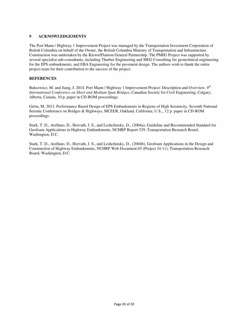
In its original configuration, Langley’s 202nd Street terminated at 88th Avenue just north of Highway 1. The PMH1 Project called for the construction of a new overpass and extension of 202nd Street to the south to provide access to a new transit facility. An interchange was required to exclusively service the highway’s transit users and high occupancy vehicles (see Figure 16). The profile of 202nd Street was lowered by approximately 2.0 m, and the profile of Highway 1 was raised by more than 4.0 m.
Figure 16 – Aerial View of Completed 202nd
Street Overpasses and EPS Embankments
A significant geotechnical challenge at 202nd Street was the presence of up to 30 m of compressible soft clay and silty sand. The addition of any load to the existing ground would trigger significant long-term settlements (similar to Kind Edward Street). A tight construction schedule and a lack of space for detours precluded the use of preloading to control settlements. EPS proved to be the most economical design solution, in conjunction with load compensating sub-excavation, to minimize ground settlements.

Page 19 of 20
A second geotechnical challenge was the presence of zones of sensitive clay that were susceptible to seismic softening and pockets of loose sand that were susceptible to liquefaction. Dynamic soil analysis performed by the geotechnical consultants indicated that mineral fill embankments behind the bridge abutments may cause a slope failure and the resulting ground movements could impact the bridge piles (see Figure 17). The use of EPS for the bridge approaches sufficiently unloaded the ground and reduced the deformations to levels that could be tolerated by the bridge piles. In this case, EPS avoided the need for extensive ground improvements.
Figure 17 – Slope Stability Schematic at 202nd
Street EPS Embankment
Approximately 100 m east of 202nd Street, the ground improved sufficiently to allow the use of mineral fill embankments retained by mechanically stabilized earth (MSE) walls. To ensure a smooth transition, the EPS blocks were benched into the fill; the steps were formed using MSE wire walls (see Figure 18). The transition was located behind EPS concrete facing panels; MSE facing panels were used once the retained fill attained full height.
Figure 18 – EPS to MSE Transition at 202nd
Street EPS Embankments
8 CONCLUSIONS
A total volume of approximately 350,000 m3 of EPS was used throughout the PMH1 Project to address a number of different geotechnical and structural challenges. It was used as a mineral fill replacement to reduce or eliminate preloading of existing ground and to control post-construction settlements. It was also used to solve slope stability issues by limiting any additional loading on the existing ground, hence avoiding the alternative of ground improvements. As shown for the Burnaby Lake area, overpasses where mineral fill embankments were not an option, EPS was used as a “green” alternative to additional bridge spans and was well suited to staged construction. As highlighted by the case studies presented, EPS should not be considered as an expensive fill replacement to mineral fill, but rather as a fast, efficient construction material that offers significant schedule advantages to building new or expanding existing infrastructure especially in locations with poor soil conditions and high seismicity.
Page 20 of 20
9 ACKNOWLEDGEMENTS
The Port Mann / Highway 1 Improvement Project was managed by the Transportation Investment Corporation of British Columbia on behalf of the Owner, the British Columbia Ministry of Transportation and Infrastructure. Construction was undertaken by the Kiewit/Flatiron General Partnership. The PMH1 Project was supported by several specialist sub-consultants, including Thurber Engineering and MEG Consulting for geotechnical engineering for the EPS embankments, and EBA Engineering for the pavement design. The authors wish to thank the entire project team for their contribution to the success of the project. REFERENCES
Buksowicz, M. and Jiang, J. 2014. Port Mann / Highway 1 Improvement Project: Description and Overview. 9th
International Conference on Short and Medium Span Bridges, Canadian Society for Civil Engineering, Calgary, Alberta, Canada, 10 p. paper in CD-ROM proceedings. Gérin, M. 2013. Performance Based Design of EPS Embankments in Regions of High Seismicity. Seventh National Seismic Conference on Bridges & Highways, MCEER, Oakland, California, U.S.,, 12 p. paper in CD-ROM proceedings. Stark, T. D., Arellano, D., Horvath, J. S., and Leshchinsky, D., (2004a), Guideline and Recommended Standard for Geofoam Applications in Highway Embankments, NCHRP Report 529, Transportation Research Board, Washington, D.C. Stark, T. D., Arellano, D., Horvath, J. S., and Leshchinsky, D., (2004b), Geofoam Applications in the Design and Construction of Highway Embankments, NCHRP Web Document 65 (Project 24-11), Transportation Research Board, Washington, D.C.