use cases.docx · web viewsmart meter (sm) def. 1meter with ... low voltage network states; ......
TRANSCRIPT
1.1 Name of the Use CaseUse Case Identification
IDArea / Domain(s)/Zone(s)
Name of the Use Case
131 Medium Voltage Network Real Time Monitoring (MVRTM)
1.2 Version ManagementVersion Management
1.3 Scope and Objectives of Use CaseScope and Objectives of Use Case
ScopeThe use case consists in collecting in a unique repository – located in the Primary Substation – measurement (mean values and PQ indexes), states and alarms from the MV grid.
Objective(s)This information is needed to perform correctly algorithms (State Estimation, State Forecasting, Optimal Power Flow, …) and control actions in order to increase the network reliability and performance.
Related businesscase(s)
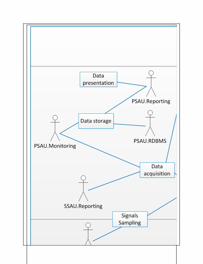
1.4 Narrative of Use CaseNarrative of Use CaseShort descriptionThe data collection for the MV grid is performed storing real-time measurements (mean values and PQ indexes), states and alarms in a unique repository – located in the Primary Substation – after managing some implementation issues, such as protocol conversion and writing of data into the PSAU.RDBMS.“Real-time” in this context means something in between 1 second and some minutes.Complete descriptionOn the MV grid, several monitoring devices will be installed:
Remote Terminal Units (RTUs), Power Quality Meters (PQMs) or – more in general – Intelligent Electronic Devices (IEDs)
Data considered by the use case are: Mean values of V, I, Q, P:
o MV busbars, MV side of transformers and MV lines in secondary substations (RTU, IED)
o On the connection point of MV customers/productions (RTU, IED) PQ indexes both from the primary substations and from some relevant secondary
substations (PQM) Status of remote-controllable elements in primary substations and in secondary
substations (RTU-IED)o breakers/disconnectorso tap changers of HV/MV transformerso voltage or reactive power set-points for generations connected on the MV
network Alarms related to events and faults (IED-PQM-RTU)
Measures, events and states not provided by those devices are provided by the Distribution Management System (DMS).The communication with the secondary substations should also be implemented.Measures are fetched from RTUs/IEDs/DMS by using the IEC61850 protocols (mainly MMS) and stored into the database which presents a data model compliant with the IEC61850.
Protocol conversion have to be implemented before writing the data – collected from different sources – into the PSAU.RDBMS to enable the execution of other use cases.
The PSAU.RDBMS should contain a Data layer, composed by a relational database, where the data are written.
The PSAU.Monitoring must include an Interface layer which implements required communication protocols and which is able to extract data from other systems.
The PSAU.Reporting is composed of an Application layer, which analyses the data to: calculate statistical values such as min, max, avg, std, etc. generate reports for DMS
1.5 General RemarksGeneral Remarks
2 Diagrams of Use Case

3 Technical Details3.1 Actors
ActorsGrouping Group Description
Actor Name Actor Type Actor DescriptionFurther information specific to this Use Case
SAU(PSAU).MMS
function
DXP, client server interface for MMSPrimary Substation Automation Unit MonitoringIt represents the monitoring functionalities which are implemented in the Primary Substation Automation Unit
SAU(PSAU).RDBMS
function
Primary Substation Automation Unit Relational Database Management System It represents the database and the related management system which compose the Primary Substation Automation Unit storage system
SAU(PSAU).IEC 104
function
Primary Substation Automation Unit ReportingIt represents the reporting functionalities which are implemented in the Primary Substation Automation Unit
DMS.MMS function DXP communication interfaceDepending on the particolar interface it can be- 104 master- 61850 client/server- Modbus/TCP master
Distribution Management System (DMS)Def. 1Application server of a Distribution Management System which hosts applications to monitor and control a distribution grid from a centralized location, typically the control center.
Def. 2DMS SCADA System refers to the real-time information system and all the elements needed to support all the relevant operational activities and functions used in distribution automation at dispatch centers and control rooms.
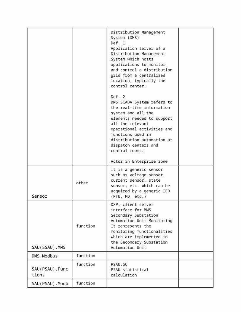
Actor in Enterprise zone
Sensorother
It is a generic sensor such as voltage sensor, current sensor, state sensor, etc. which can be acquired by a generic IED (RTU, PD, etc.)
SAU(SSAU).MMS
function
DXP, client server interface for MMSSecondary Substation Automation Unit MonitoringIt represents the monitoring functionalities which are implemented in the Secondary Substation Automation Unit
DMS.Modbus function
SAU(PSAU).Functions
function PSAU.SCPSAU statistical calculation
SAU(PSAU).Modbus function
DMS.IEC104 function
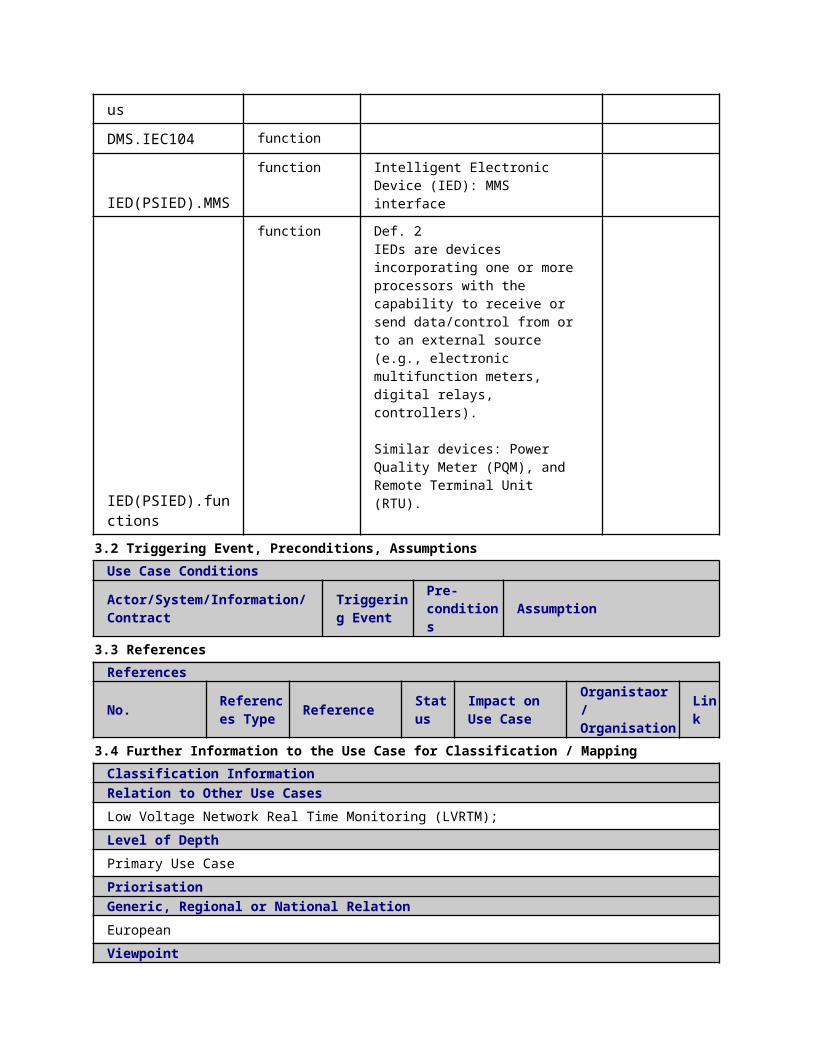
IED(PSIED).MMSfunction Intelligent Electronic Device (IED):
MMS interface
IED(PSIED).functions
function Def. 2IEDs are devices incorporating one or more processors with the capability to receive or send data/control from or to an external source (e.g., electronic multifunction meters, digital relays, controllers).
Similar devices: Power Quality Meter (PQM), and Remote Terminal Unit (RTU).
3.2 Triggering Event, Preconditions, AssumptionsUse Case ConditionsActor/System/Information/Contract
Triggering Event
Pre-conditions Assumption
3.3 ReferencesReferences
No. References Type Reference Statu
sImpact on Use Case
Organistaor / Organisation
Link
3.4 Further Information to the Use Case for Classification / MappingClassification InformationRelation to Other Use CasesLow Voltage Network Real Time Monitoring (LVRTM);Level of DepthPrimary Use CasePriorisationGeneric, Regional or National Relation
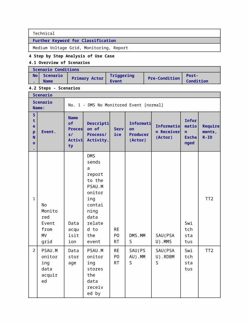
EuropeanViewpointTechnicalFurther Keyword for ClassificationMedium Voltage Grid, Monitoring, Report
4 Step by Step Analysis of Use Case4.1 Overview of Scenarios
Scenario ConditionsNo.
Scenario Name Primary Actor Triggering Event Pre-Condition Post-Condition
4.2 Steps - ScenariosScenarioScenario Name: No. 1 - DMS No Monitored Event [normal]Step No.
Event.
Name of Process/ Activity
Description of Process/ Activity.
Service
Information Producer (Actor)
Information Receiver (Actor)
Information Exchanged
Requirements, R-ID
1No Monitored Event from MV grid
Data acquisition
DMS sends a report to the PSAU.Monitoring containing data related to the event
REPORT
DMS.MMS
SAU(PSAU).MMS
Switch status
TT2
2
PSAU.Monitoring data acquired
Data storage
PSAU.Monitoring stores the data received by the DMS into the PSAU.RDBMS
REPORT
SAU(PSAU).MMS
SAU(PSAU).RDBMS
Switch status
TT2
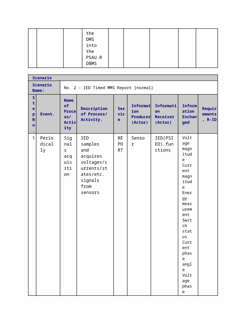
ScenarioScenario Name: No. 2 - IED Timed MMS Report [normal]
Step No.
Event. Name of Process/ Activit
Description of Process/ Activity.
Service
Information Producer (Actor)
Information Receiver (Actor)
Information Exchanged
Requirements, R-ID
y
1
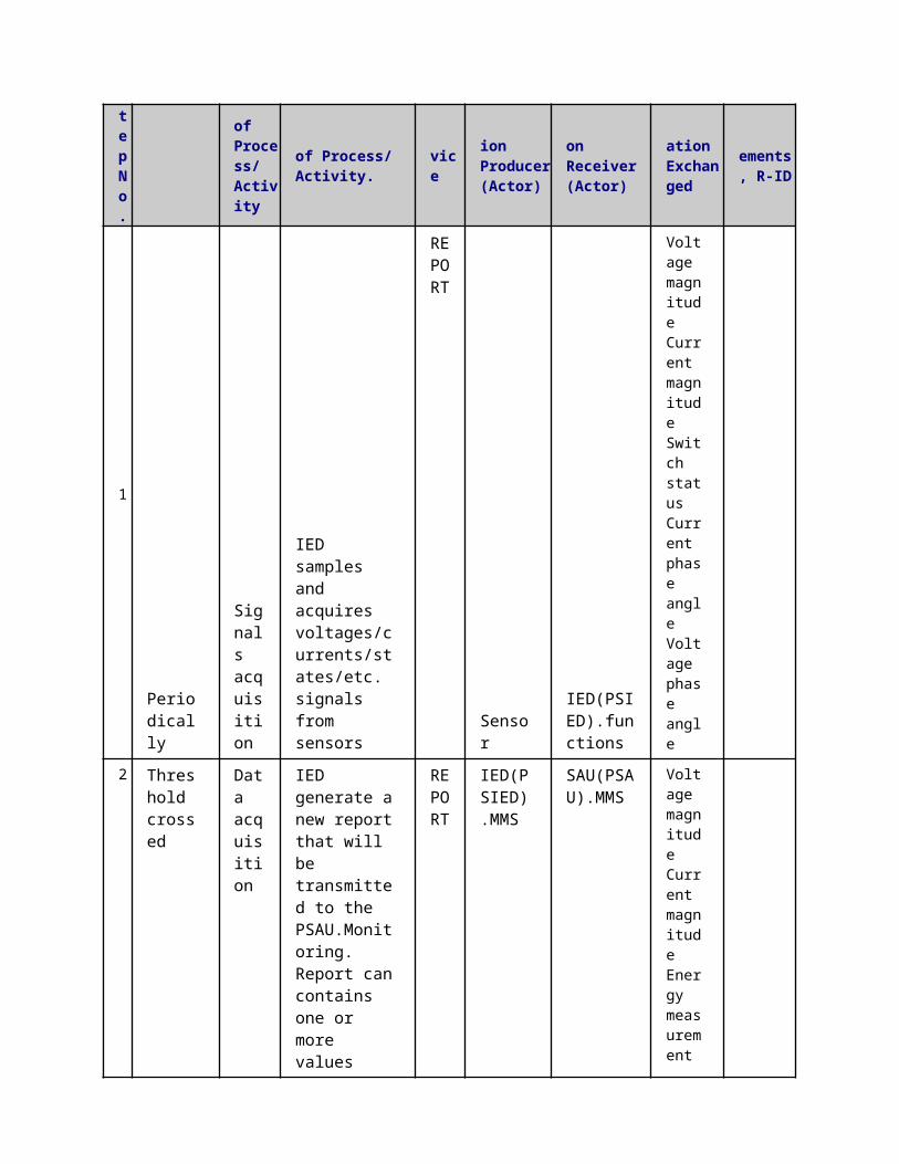
Periodically
Signals acquisition
IED samples and acquires voltages/currents/states/etc. signals from sensors
REPORT
SensorIED(PSIED).functions
Voltage magnitude Current magnitude Energy measurement Switch status Current phase angle Voltage phase angle Reactive power
Active power
2 Periodically
Data acquisition
IED generates a new report that will be transmitted to the PSAU.Monitoring. Report can contains one or more values
REPORT
IED(PSIED).MMS
SAU(PSAU).MMS
Voltage magnitude Current magnitude Energy measurement Switch status Current phase angle Voltage phase angle Reactive power
Active power
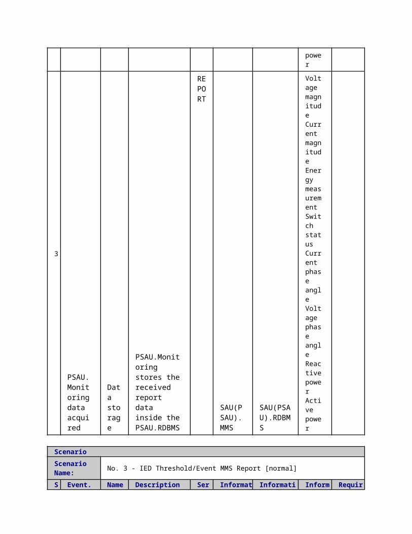
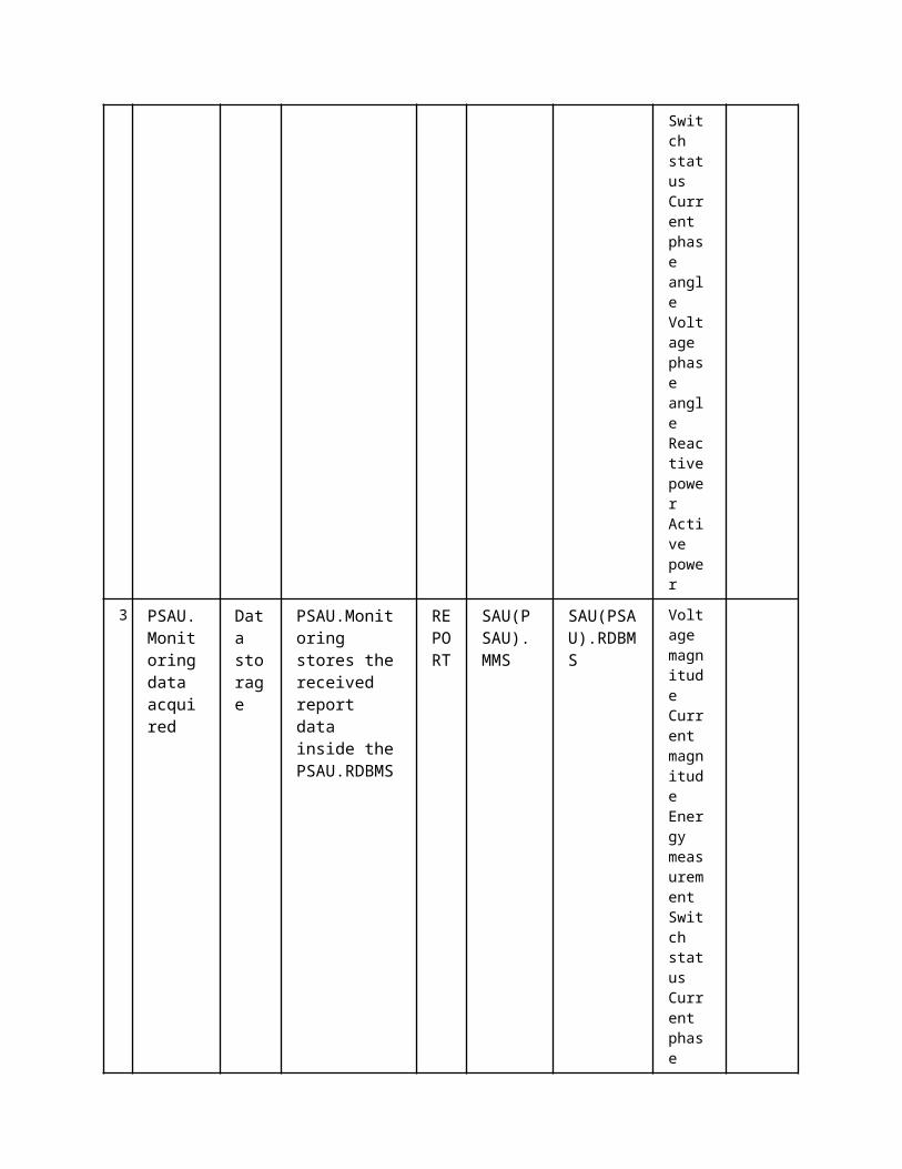
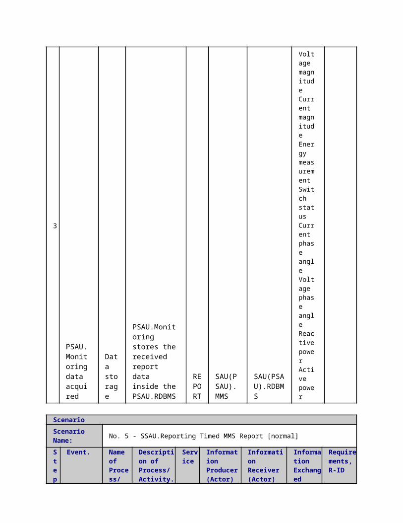
3
PSAU.Monitoring data acquired
Data storage
PSAU.Monitoring stores the received report data inside the PSAU.RDBMS
REPORT
SAU(PSAU).MMS
SAU(PSAU).RDBMS
Voltage magnitude Current magnitude Energy measurement Switch status Current phase angle Voltage phase angle Reactive power
Active power
ScenarioScenario Name: No. 3 - IED Threshold/Event MMS Report [normal]
Step No.
Event.
Name of Process/ Activity
Description of Process/ Activity.
Service
Information Producer (Actor)
Information Receiver (Actor)
Information Exchanged
Requirements, R-ID
1 Periodically
Signals acquisition
IED samples and acquires voltages/currents/states/etc. signals from sensors
REPORT
Sensor IED(PSIED).functions
Voltage magnitude Current magnitude Switch status Current

phase angle Voltage phase angle
2
Threshold crossed
Data acquisition
IED generate a new report that will be transmitted to the PSAU.Monitoring. Report can contains one or more values
REPORT
IED(PSIED).MMS
SAU(PSAU).MMS
Voltage magnitude Current magnitude Energy measurement Switch status Current phase angle Voltage phase angle Reactive power
Active power
3 PSAU.Monitoring data acquired
Data storage
PSAU.Monitoring stores the received report data inside the PSAU.RDBMS
REPORT
SAU(PSAU).MMS
SAU(PSAU).RDBMS
Voltage magnitude Current magnitude Energy measurement Switch status Current phase angle Voltag
e phase angle Reactive power
Active power
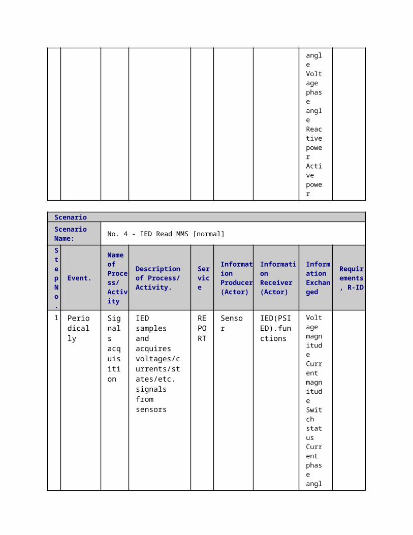
ScenarioScenario Name: No. 4 - IED Read MMS [normal]
Step No.
Event.
Name of Process/ Activity
Description of Process/ Activity.
Service
Information Producer (Actor)
Information Receiver (Actor)
Information Exchanged
Requirements, R-ID
1
Periodically
Signals acquisition
IED samples and acquires voltages/currents/states/etc. signals from sensors
REPORT Sensor
IED(PSIED).functions
Voltage magnitude Current magnitude Switch status Current phase angle Voltage phase angle
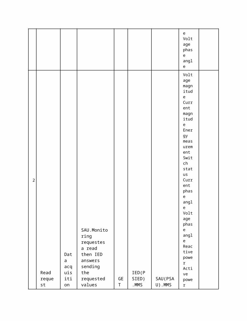
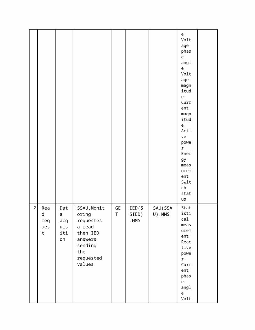
2 Read request
Data acquisition
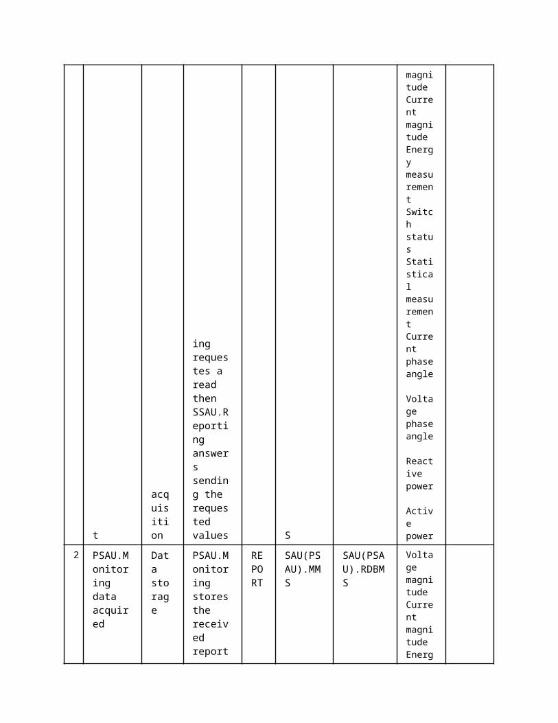
SAU.Monitoring requestes a read then IED answers sending the requested values
GET
IED(PSIED).MMS
SAU(PSAU).MMS
Voltage magnitude Current magnitude Energy measurement Switch status Current
phase angle Voltage phase angle Reactive power
Active power
3
PSAU.Monitoring data acquired
Data storage
PSAU.Monitoring stores the received report data inside the PSAU.RDBMS
REPORT
SAU(PSAU).MMS
SAU(PSAU).RDBMS
Voltage magnitude Current magnitude Energy measurement Switch status Current phase angle Voltage phase angle Reactive power
Active power
ScenarioScenario Name: No. 5 - SSAU.Reporting Timed MMS Report [normal]
Step No.
Event.
Name of Process/ Activity
Description of Process/ Activity.
Service
Information Producer (Actor)
Information Receiver (Actor)
Information Exchanged
Requirements, R-ID
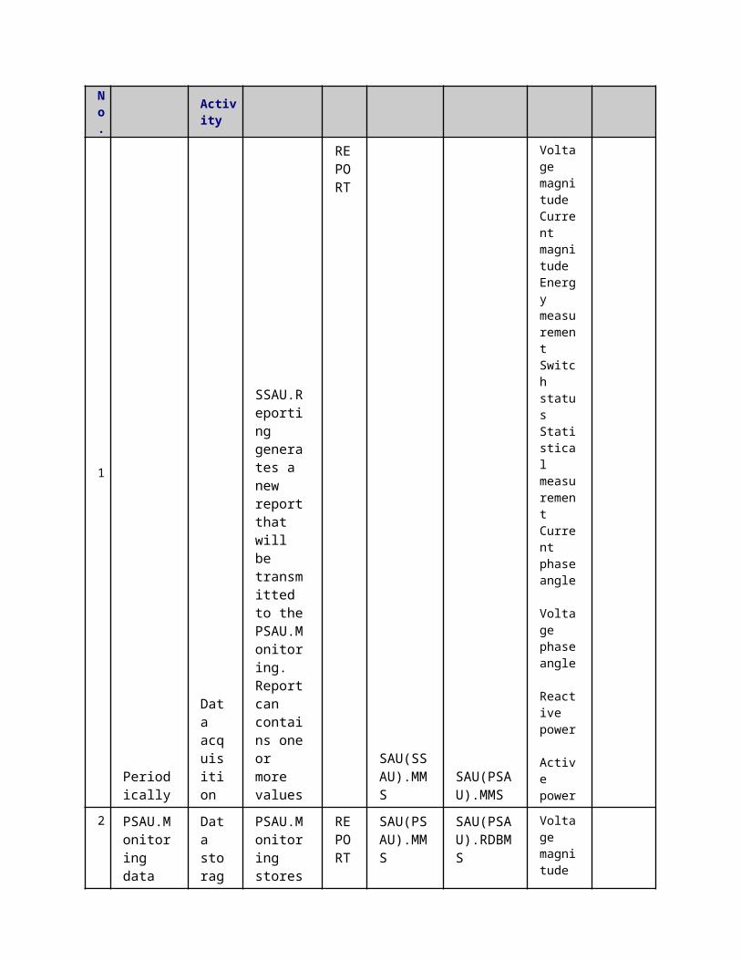
1 Periodically
Data acquisition
SSAU.Reporting generates
REPORT
SAU(SSAU).MMS
SAU(PSAU).MMS
Voltage magnit
a new report that will be transmitted to the PSAU.Monitoring. Report can contains one or more values
ude Current magnitude Energy measurement Switch status Statistical measurement Current phase angle Voltage phase angle Reactive power Active power
2
PSAU.Monitoring data acquired
Data storage
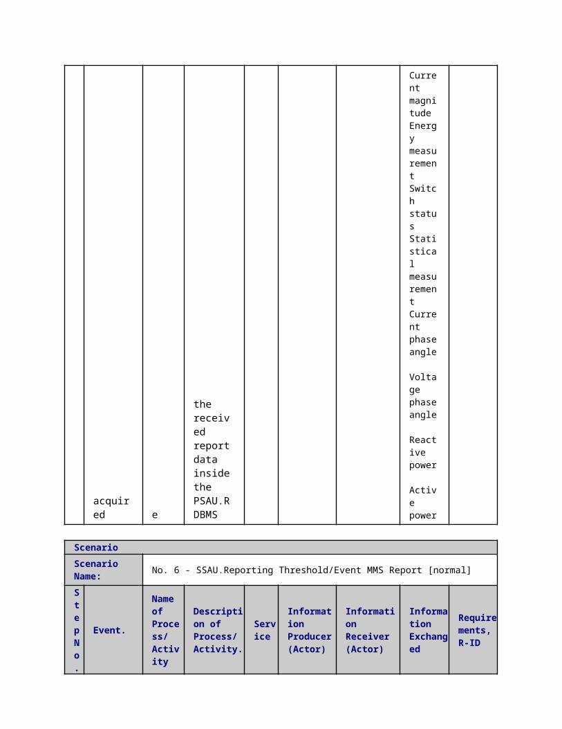
PSAU.Monitoring stores the received report data inside the PSAU.RDBMS
REPORT
SAU(PSAU).MMS
SAU(PSAU).RDBMS
Voltage magnitude Current magnitude Energy measurement Switch status Statistical measurement Current phase angle Voltage phase angle Reactive power Active power
Scenario
Scenario Name: No. 6 - SSAU.Reporting Threshold/Event MMS Report [normal]
Step No.
Event.
Name of Process/ Activity
Description of Process/ Activity.
Service
Information Producer (Actor)
Information Receiver (Actor)
Information Exchanged
Requirements, R-ID
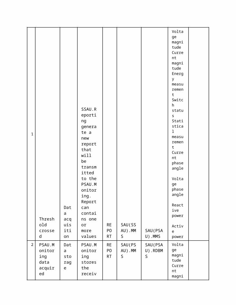
1
Threshold crossed
Data acquisition
SSAU.Reporting generate a new report that will be transmitted to the PSAU.Monitoring. Report can contains one or more values
REPORT
SAU(SSAU).MMS
SAU(PSAU).MMS
Voltage magnitude Current magnitude Energy measurement Switch status Statistical measurement Current phase angle Voltage phase angle Reactive power Active power
2 PSAU.Monitoring data acquired
Data storage
PSAU.Monitoring stores the received report data inside the PSAU.RDBMS
REPORT
SAU(PSAU).MMS
SAU(PSAU).RDBMS
Voltage magnitude Current magnitude Energy measurement Switch status Statistical measurement Current phase angle
Voltage phase angle Reactive power Active power
ScenarioScenario Name: No. 7 - SSAU.Reporting Read MMS [normal]
Step No.
Event.
Name of Process/ Activity
Description of Process/ Activity.
Service
Information Producer (Actor)
Information Receiver (Actor)
Information Exchanged
Requirements, R-ID
1
Read request
Data acquisition
PSAU.Monitoring requestes a read then SSAU.Reporting answers sending the requested values
GET
SAU(SSAU).MMS
SAU(PSAU).MMS
Voltage magnitude Current magnitude Energy measurement Switch status Statistical measurement Current phase angle Voltage phase angle Reactive power Active power
2 PSAU.Monitoring data acquired
Data storage
PSAU.Monitoring stores the received report
REPORT
SAU(PSAU).MMS
SAU(PSAU).RDBMS
Voltage magnitude Current magnitude
data inside the PSAU.RDBMS
Energy measurement Switch status Statistical measurement Current phase angle Voltage phase angle Reactive power Active power
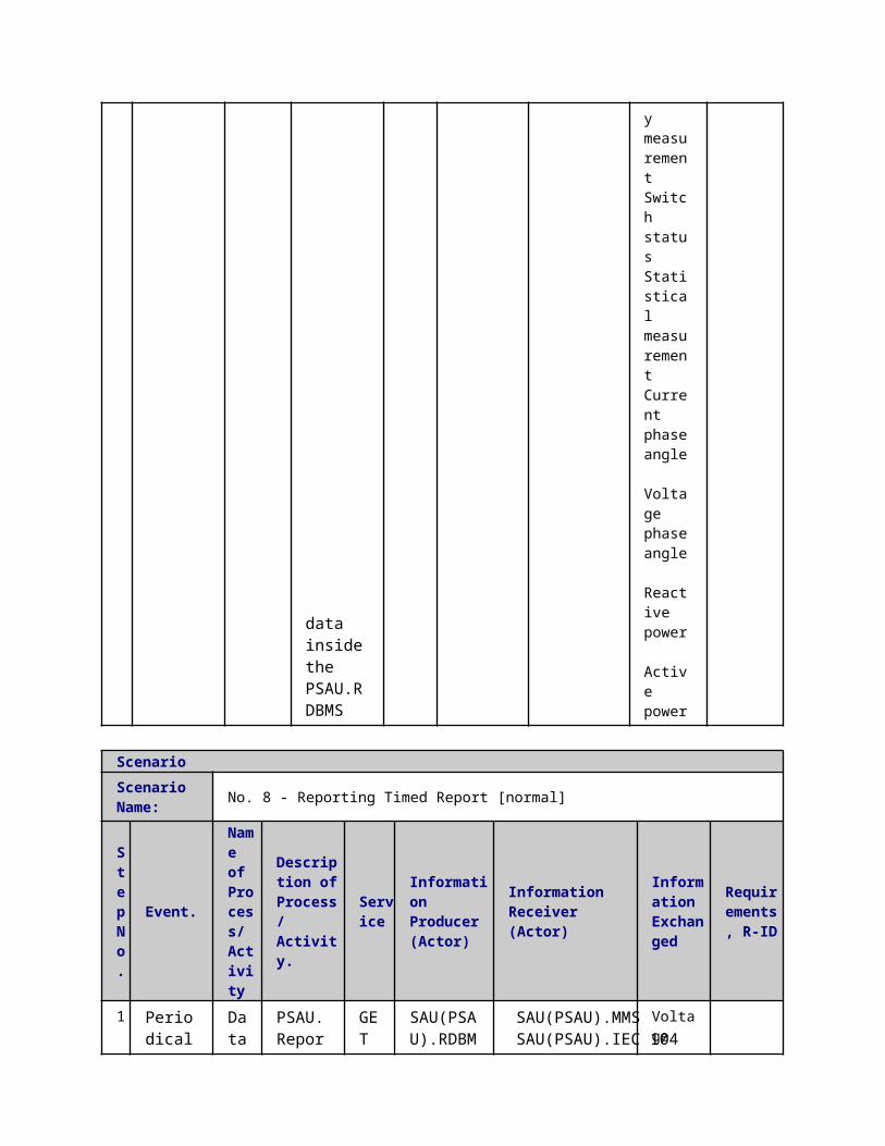
ScenarioScenario Name: No. 8 - Reporting Timed Report [normal]
Step No.
Event.
Name of Process/ Activity
Description of Process/ Activity.
Service
Information Producer (Actor)
Information Receiver (Actor)
Information Exchanged
Requirements, R-ID
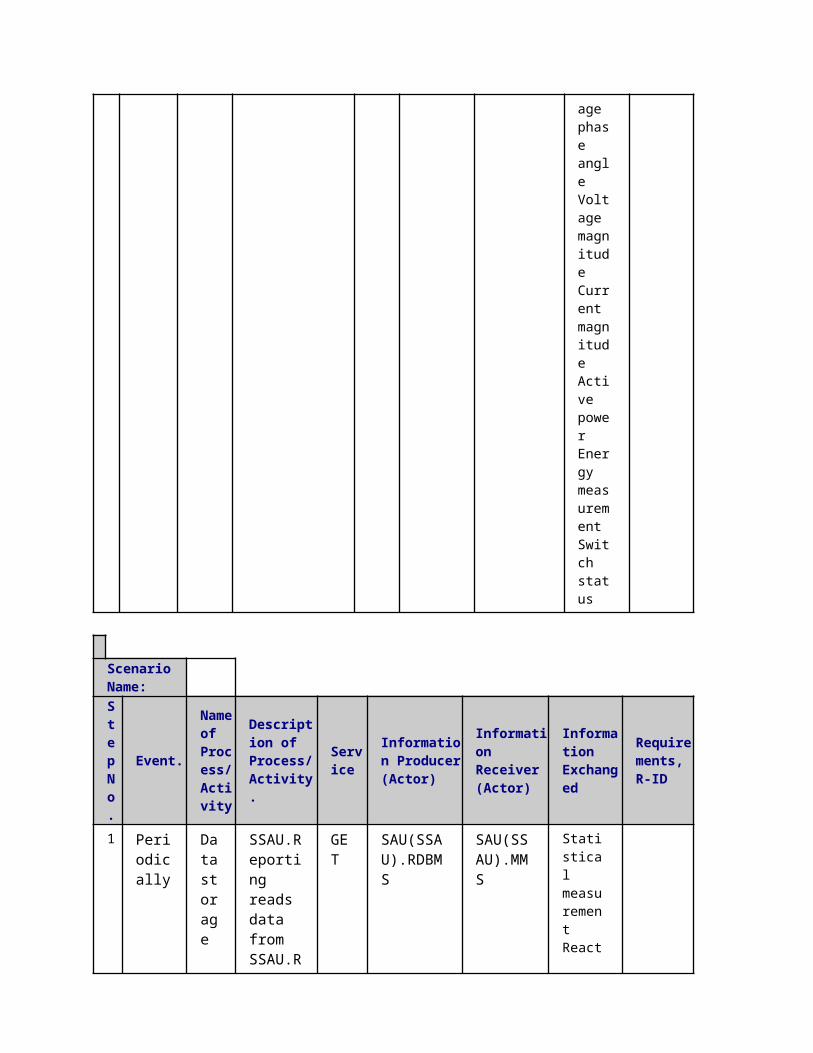
1 Periodically
Data storage
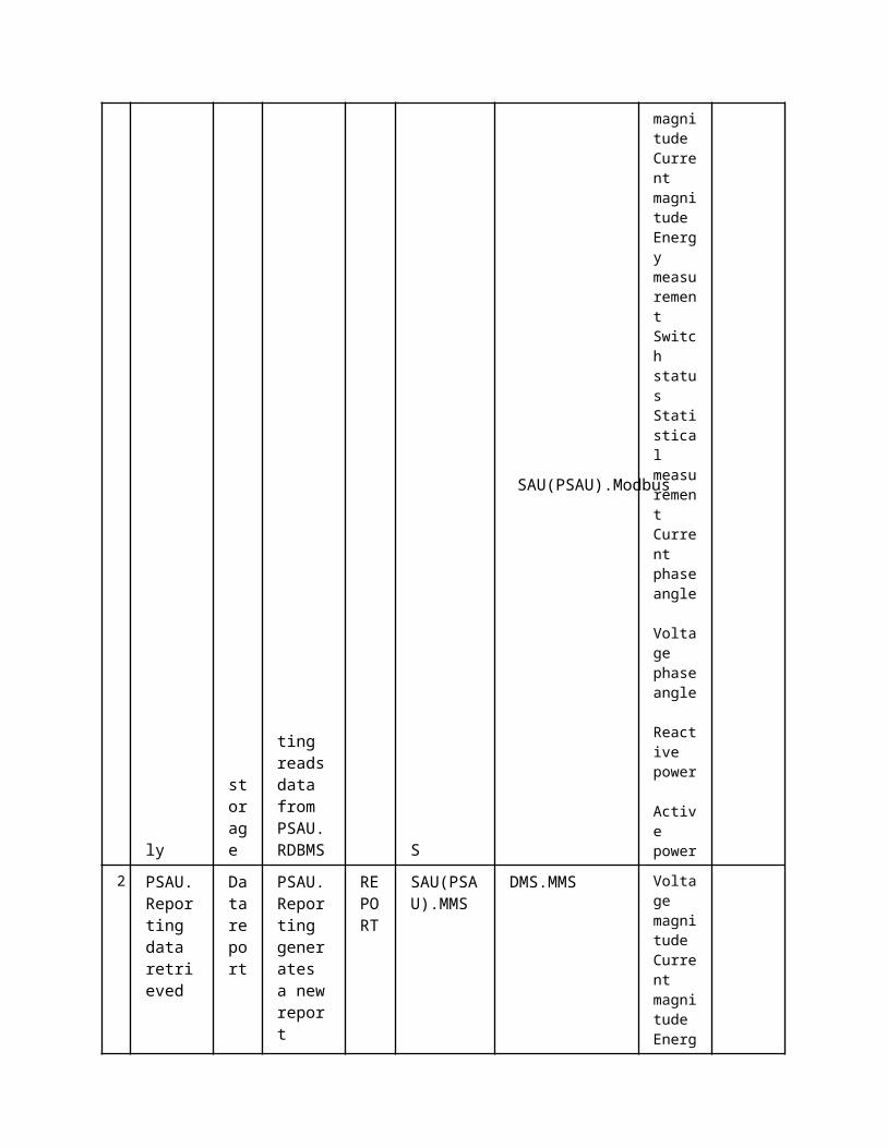
PSAU.Reporting reads data from PSAU.RDBMS
GET
SAU(PSAU).RDBMS
SAU(PSAU).MMSSAU(PSAU).IEC 104SAU(PSAU).Modbus
Voltage magnitude Current magnitude Energy measurement Switch status Statistical measurement Current phase angle
Voltage phase angle Reactive power Active power
2
PSAU.Reporting data retrieved
Data report
PSAU.Reporting generates a new report which contains the data retrieved from PSAU.RDBMS
REPORT
SAU(PSAU).MMS DMS.MMS
Voltage magnitude Current magnitude Energy measurement Switch status Statistical measurement Current phase angle Voltage phase angle Reactive power Active power
3 PSAU.Reporting data retrieved
Data report
PSAU.Reporting generates a new report which contains the data
REPORT
SAU(PSAU).Modbus
DMS.Modbus Voltage magnitude Current magnitude Energy measurement
retrieved from PSAU.RDBMS
Switch status Statistical measurement Current phase angle Voltage phase angle Reactive power Active power
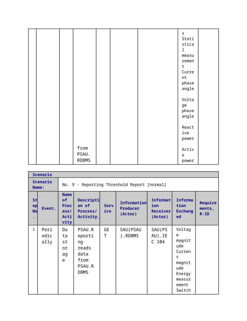
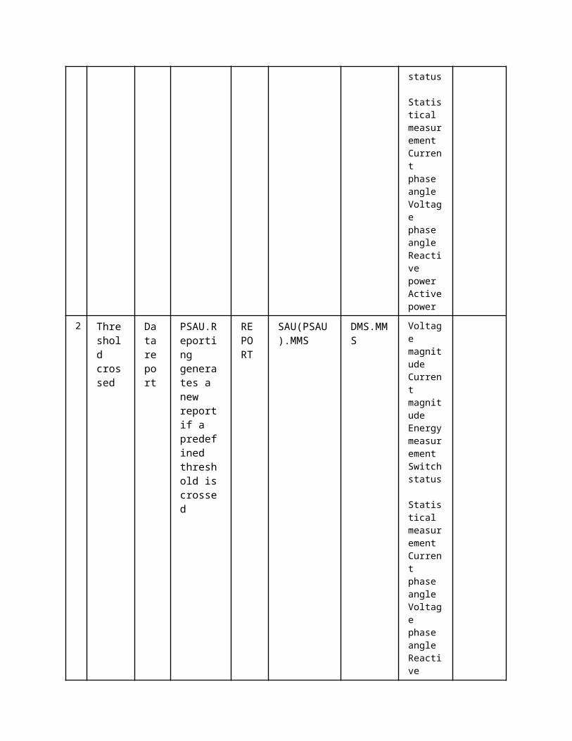
ScenarioScenario Name: No. 9 - Reporting Threshold Report [normal]
Step No.
Event.
Name of Process/ Activity
Description of Process/ Activity.
Service
Information Producer (Actor)
Information Receiver (Actor)
Information Exchanged
Requirements, R-ID
1 Periodically
Data storage
PSAU.Reporting reads data from PSAU.RDBMS
GET SAU(PSAU).RDBMS
SAU(PSAU).IEC 104
Voltage magnitude Current magnitude Energy measurement Switch status Statistical measurement Current phase angle Voltage phase angle Reactive power
Active
power
2
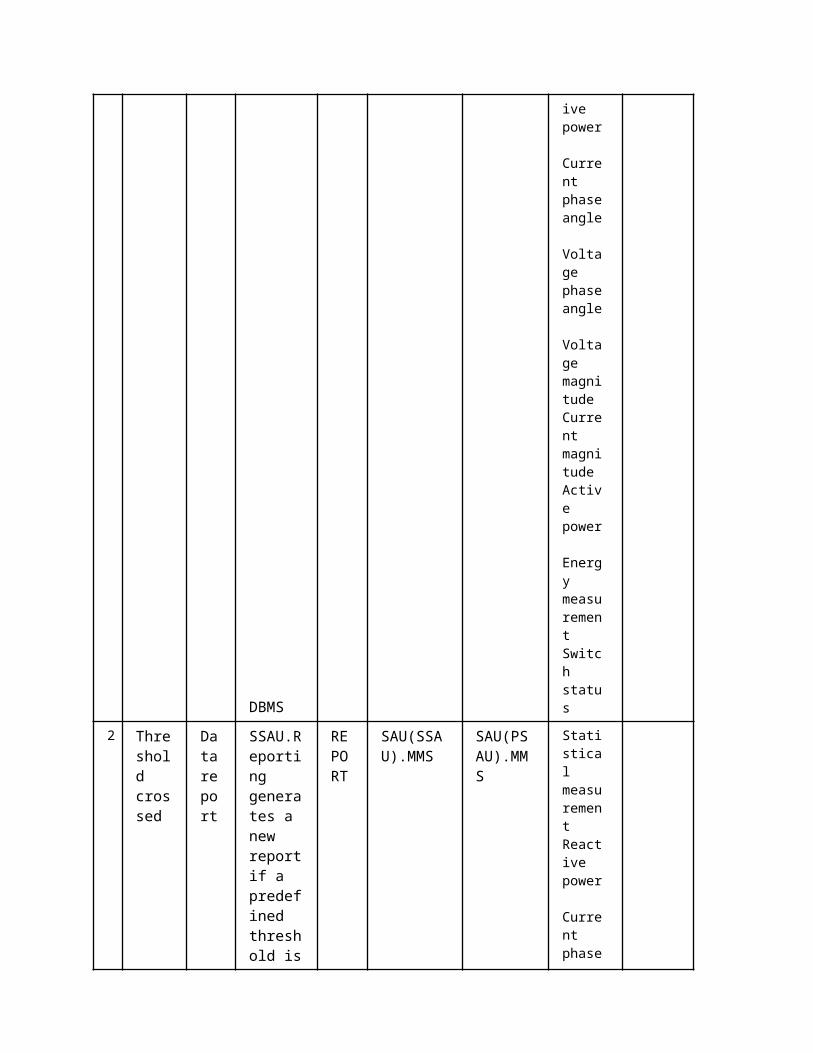
Threshold crossed
Data report
PSAU.Reporting generates a new report if a predefined threshold is crossed
REPORT
SAU(PSAU).MMS
DMS.MMS
Voltage magnitude Current magnitude Energy measurement Switch status Statistical measurement Current phase angle Voltage phase angle Reactive power
Active power
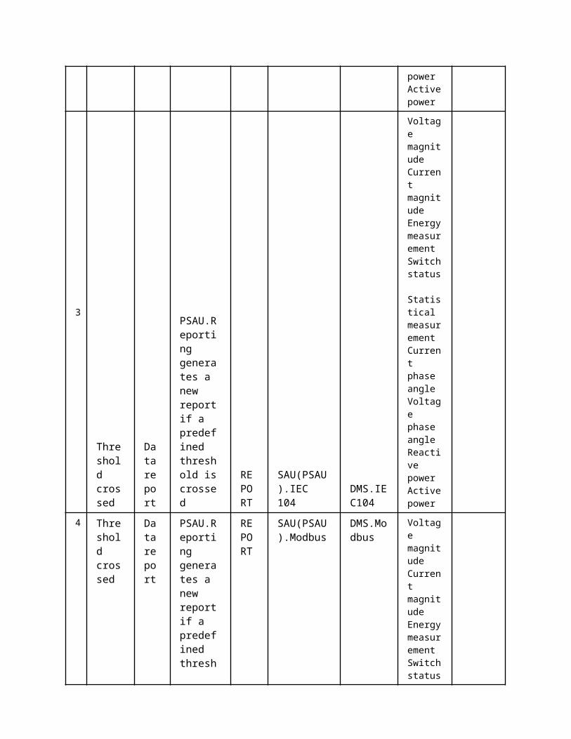
3
Threshold crossed
Data report
PSAU.Reporting generates a new report if a predefined threshold is crossed
REPORT
SAU(PSAU).IEC 104
DMS.IEC104
Voltage magnitude Current magnitude Energy measurement Switch status Statistical measurement Current phase angle Voltage phase angle Reactive power
Active power
4 Thresh Dat PSAU.Rep REP SAU(PSAU). DMS.Mo Voltage magnitu

old crossed
a report
orting generates a new report if a predefined threshold is crossed ORT Modbus dbus
de Current magnitude Energy measurement Switch status Statistical measurement Current phase angle Voltage phase angle Reactive power
Active power
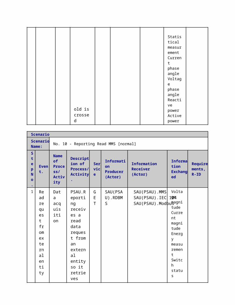
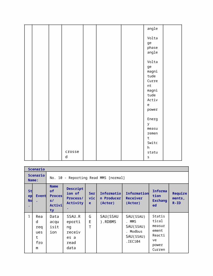
ScenarioScenario Name: No. 10 - Reporting Read MMS [normal]
Step No.
Event.
Name of Process/ Activity
Description of Process/ Activity.
Service
Information Producer (Actor)
Information Receiver (Actor)
Information Exchanged
Requirements, R-ID
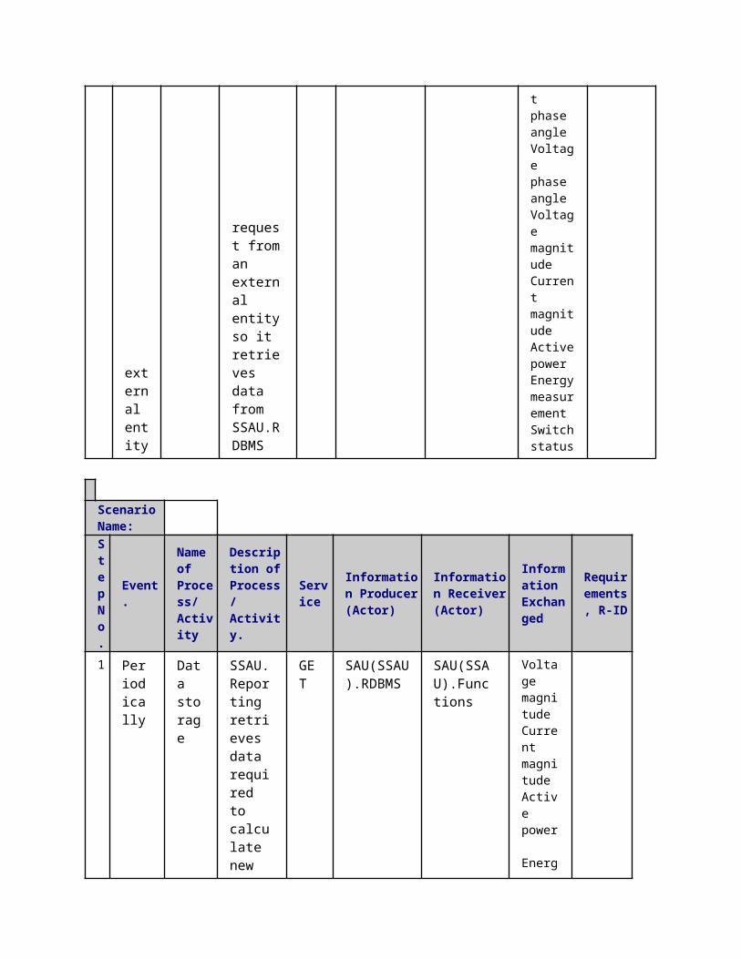
1 Read request from external entity
Data acquisition
PSAU.Reporting receives a read data request from an external entity so it retrieves data from PSAU.RDBMS
GET
SAU(PSAU).RDBMS
SAU(PSAU).MMSSAU(PSAU).IEC 104SAU(PSAU).Modbus
Voltage magnitude Current magnitude Energy measurement
Switch status Statistical measurement
Current phase
angle Voltage phase angle Reactive power Active power
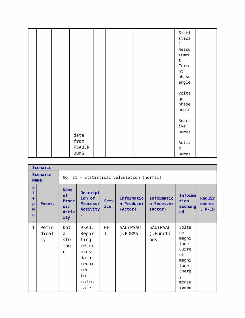
ScenarioScenario Name: No. 11 - Statistical Calculation [normal]
Step No.
Event.
Name of Process/ Activity
Description of Process/ Activity.
Service
Information Producer (Actor)
Information Receiver (Actor)
Information Exchanged
Requirements, R-ID
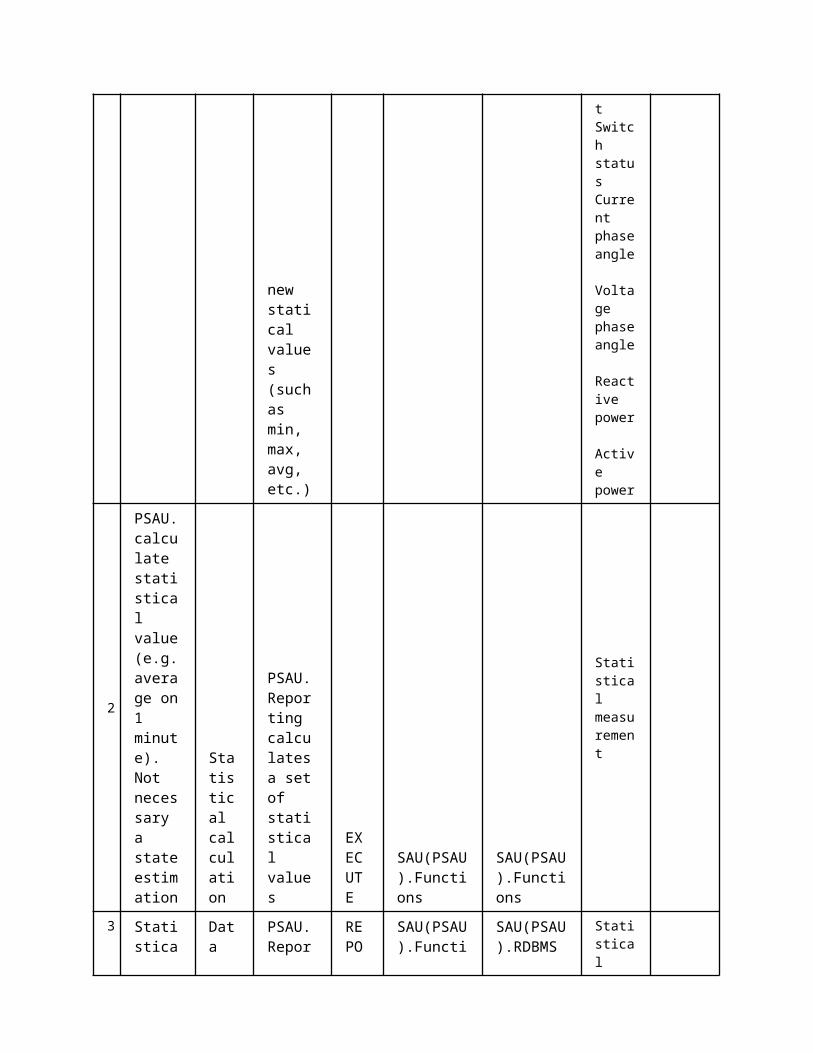
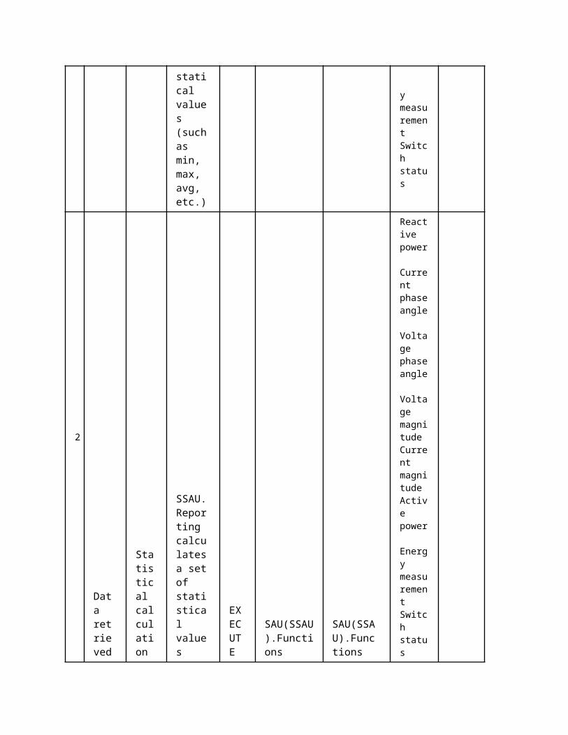
1
Periodically
Data storage
PSAU.Reporting retrieves data required to calculate new statical values (such as min, max, avg, etc.) GET
SAU(PSAU).RDBMS
SAU(PSAU).Functions
Voltage magnitude Current magnitude Energy measurement
Switch status Current phase angle Voltage phase angle Reactive power Active power
2 PSAU.calculate statistical value (e.g. average
Statistical calculation
PSAU.Reporting calculates a set of statistic
EXECUTE
SAU(PSAU).Functions
SAU(PSAU).Functions
Statistical measurement
on 1 minute). Not necessary a state estimation al values
3
Statistical data calculated
Data storage
PSAU.Reporting stores the calculated statical data inside the PSAU.RDBMS
REPORT
SAU(PSAU).Functions
SAU(PSAU).RDBMS
Statistical measurement
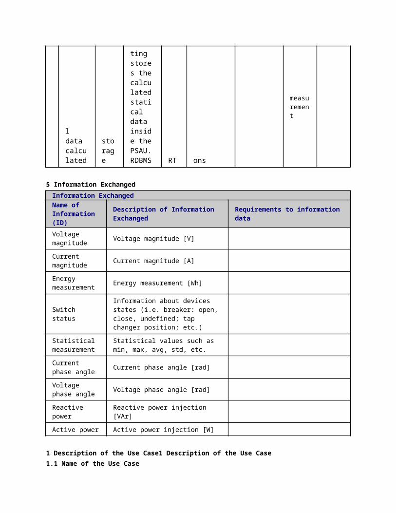
5 Information ExchangedInformation ExchangedName of Information (ID)
Description of Information Exchanged Requirements to information data
Voltage magnitude Voltage magnitude [V]
Current magnitude Current magnitude [A]
Energy measurement Energy measurement [Wh]
Switch statusInformation about devices states (i.e. breaker: open, close, undefined; tap changer position; etc.)
Statistical measurement
Statistical values such as min, max, avg, std, etc.
Current phase angle Current phase angle [rad]
Voltage phase angle Voltage phase angle [rad]
Reactive power Reactive power injection [VAr]
Active power Active power injection [W]
1 Description of the Use Case1 Description of the Use Case1.1 Name of the Use Case
Use Case Identification
IDArea / Domain(s)/Zone(s)
Name of the Use Case
132 Low Voltage Network Real Time Monitoring (LVRTM)
1.2 Version ManagementVersion Management
1.3 Scope and Objectives of Use CaseScope and Objectives of Use Case
ScopeThe use case consists in collecting in a unique repository – located in the Secondary Substation – measurement (mean values and PQ indexes), states and alarms from the LV grid.
Objective(s)This information is needed to perform correctly algorithms (State Estimation, State Forecasting, Optimal Power Flow, …) and control actions in order to increase the network reliability and performance.
Related businesscase(s)
1.4 Narrative of Use CaseNarrative of Use CaseShort descriptionThe data collection for the LV grid is performed storing real-time measurements (mean values and PQ indexes), states and alarms in a unique repository – located in the Secondary Substation – after managing some implementation issues, such as protocol conversion and writing of data into the SSAU.RDBMS.“Real-time” in this context means something in between 1 second and some minutes.Complete descriptionOn the LV grid, several monitoring devices will be installed:
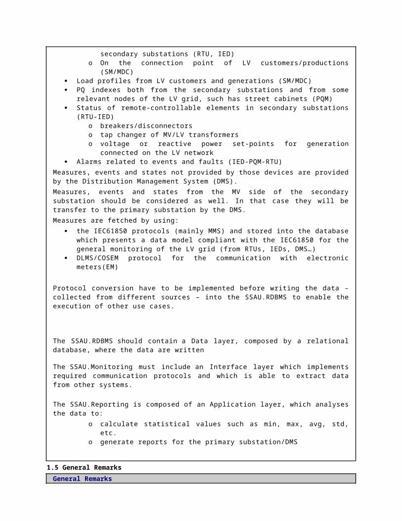
Smart Meters (SM) on the connection point of LV customers/productions. Data of SMs are often collected by a Meter Data Collector (MDC) system, installed in the secondary substation and aggregated in an Automatic Metering Management system (AMM) located in the control center.
Remote Terminal Units (RTUs), Power Quality Meters (PQMs) or – more in general – Intelligent Electronic Devices (IEDs)
Data considered by the use case is: Mean values of V, I, Q, P:
o LV busbars, LV side of transformers and LV lines in secondary substations (RTU, IED)
o On the connection point of LV customers/productions (SM/MDC) Load profiles from LV customers and generations (SM/MDC) PQ indexes both from the secondary substations and from some relevant nodes of the
LV grid, such has street cabinets (PQM) Status of remote-controllable elements in secondary substations (RTU-IED)
o breakers/disconnectorso tap changer of MV/LV transformerso voltage or reactive power set-points for generation connected on the LV
network Alarms related to events and faults (IED-PQM-RTU)
Measures, events and states not provided by those devices are provided by the Distribution Management System (DMS).

Measures, events and states from the MV side of the secondary substation should be considered as well. In that case they will be transfer to the primary substation by the DMS.Measures are fetched by using:
the IEC61850 protocols (mainly MMS) and stored into the database which presents a data model compliant with the IEC61850 for the general monitoring of the LV grid (from RTUs, IEDs, DMS…)
DLMS/COSEM protocol for the communication with electronic meters(EM)
Protocol conversion have to be implemented before writing the data – collected from different sources – into the SSAU.RDBMS to enable the execution of other use cases.
The SSAU.RDBMS should contain a Data layer, composed by a relational database, where the data are written
The SSAU.Monitoring must include an Interface layer which implements required communication protocols and which is able to extract data from other systems.
The SSAU.Reporting is composed of an Application layer, which analyses the data to:o calculate statistical values such as min, max, avg, std, etc.o generate reports for the primary substation/DMS
1.5 General RemarksGeneral Remarks
2 Diagrams of Use Case
3 Technical Details3.1 Actors
ActorsGrouping Group Description
Actor Name Actor Type Actor DescriptionFurther information specific to this Use Case
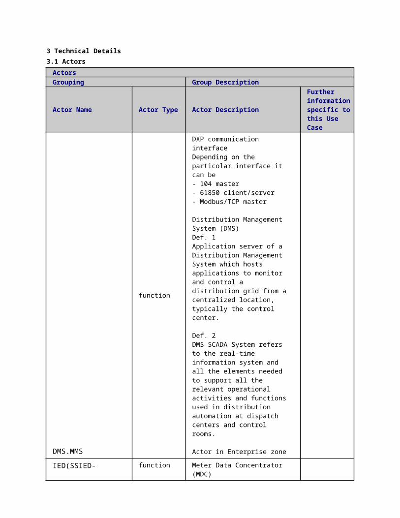
DMS.MMS
function
DXP communication interfaceDepending on the particolar interface it can be- 104 master- 61850 client/server- Modbus/TCP master
Distribution Management System (DMS)Def. 1Application server of a Distribution Management System which hosts applications to monitor and control a distribution grid from a centralized location, typically the control center.
Def. 2DMS SCADA System refers to the real-time information system and all the elements needed to support all the relevant operational activities and functions used in distribution automation at dispatch centers and control rooms.
Actor in Enterprise zone
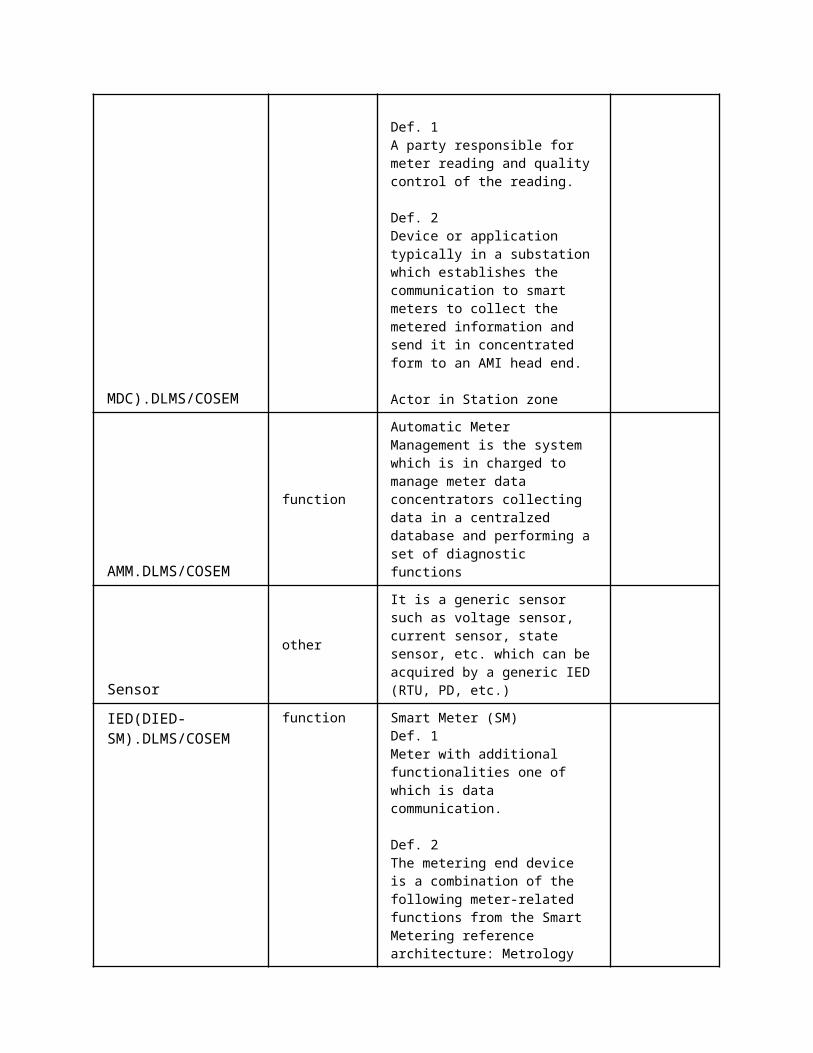
IED(SSIED-MDC).DLMS/COSEM
function
Meter Data Concentrator (MDC)
Def. 1A party responsible for meter reading and quality control of the reading.
Def. 2Device or application typically in a substation which establishes the communication to smart meters to collect the metered information and send it in concentrated form to an AMI head end.
Actor in Station zone
AMM.DLMS/COSEM function Automatic Meter Management is the system which is in charged to manage meter data concentrators collecting data in a centralzed
database and performing a set of diagnostic functions
Sensor
other
It is a generic sensor such as voltage sensor, current sensor, state sensor, etc. which can be acquired by a generic IED (RTU, PD, etc.)
IED(DIED-SM).DLMS/COSEM
function
Smart Meter (SM)Def. 1Meter with additional functionalities one of which is data communication.
Def. 2The metering end device is a combination of the following meter-related functions from the Smart Metering reference architecture: Metrology functions including the conventional meter display (register or index) that are under legal metrological control. When under metrological control, these functions shall meet the essential requirements of the MID; One or more additional functions not covered by the MID. These may also make use of the display; Meter communication functions
Actor in the Field zone
SAU(SSAU).MMS
function
DXP, client server interface for MMSSecondary Substation Automation Unit MonitoringIt represents the monitoring functionalities which are implemented in the Secondary Substation Automation Unit
SAU(SSAU).RDBMS
function
Secondary Substation Automation Unit Relational Database Management System It represents the database and the related management system which compose the Secondary Substation Automation Unit storage system
SAU(PSAU).MMS function DXP, client server interface for MMSPrimary Substation Automation Unit MonitoringIt represents the monitoring functionalities which are implemented in the Primary
Substation Automation Unit
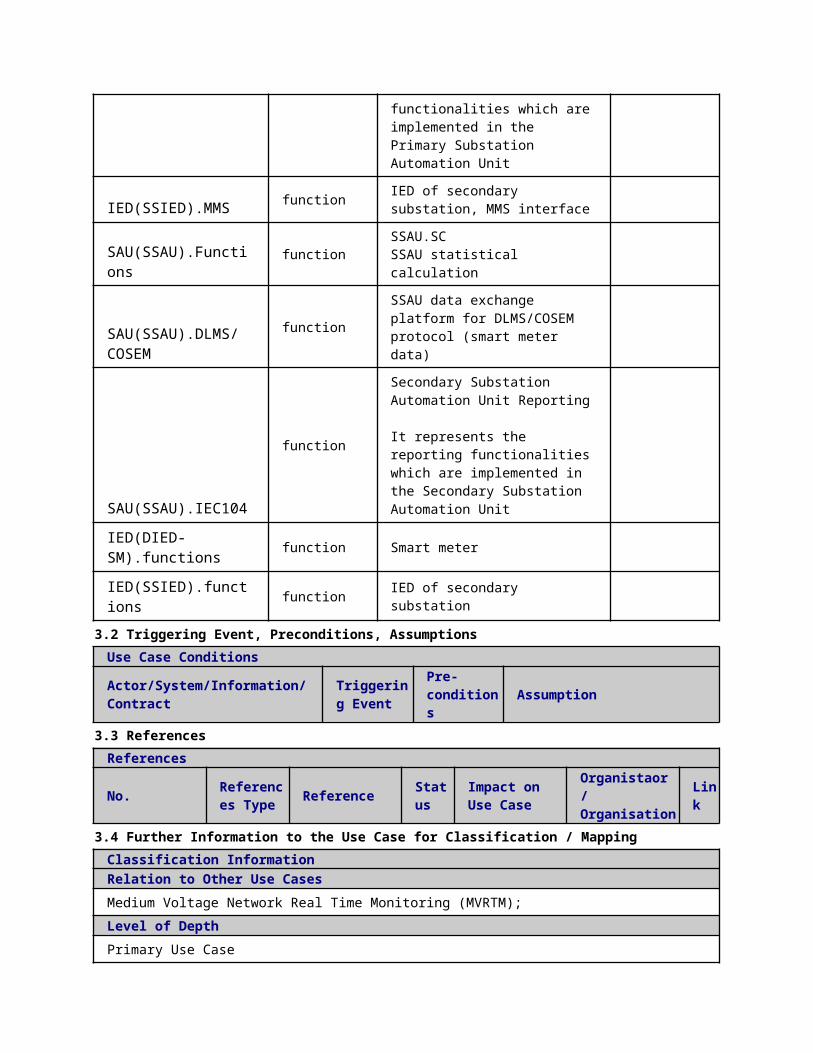
IED(SSIED).MMS function IED of secondary substation, MMS interface
SAU(SSAU).Functions function SSAU.SCSSAU statistical calculation
SAU(SSAU).DLMS/COSEM
functionSSAU data exchange platform for DLMS/COSEM protocol (smart meter data)
SAU(SSAU).IEC104
function
Secondary Substation Automation Unit Reporting It represents the reporting functionalities which are implemented in the Secondary Substation Automation Unit
IED(DIED-SM).functions function Smart meter
IED(SSIED).functions function IED of secondary substation
3.2 Triggering Event, Preconditions, AssumptionsUse Case ConditionsActor/System/Information/Contract
Triggering Event
Pre-conditions Assumption
3.3 ReferencesReferences
No. References Type Reference Statu
sImpact on Use Case
Organistaor / Organisation
Link
3.4 Further Information to the Use Case for Classification / MappingClassification InformationRelation to Other Use CasesMedium Voltage Network Real Time Monitoring (MVRTM);Level of DepthPrimary Use CasePriorisationGeneric, Regional or National RelationEuropeanViewpointTechnicalFurther Keyword for ClassificationLow Voltage Grid, Monitoring, Report, DLMS/COSEM
4 Step by Step Analysis of Use Case4.1 Overview of Scenarios
Scenario ConditionsNo.
Scenario Name Primary Actor Triggering Event Pre-Condition Post-Condition
4.2 Steps - Scenarios
Scenario
Name:Step No.
Event.
Name of Process/ Activity
Description of Process/ Activity.
Service
Information Producer (Actor)
Information Receiver (Actor)
Information Exchanged
Requirements, R-ID
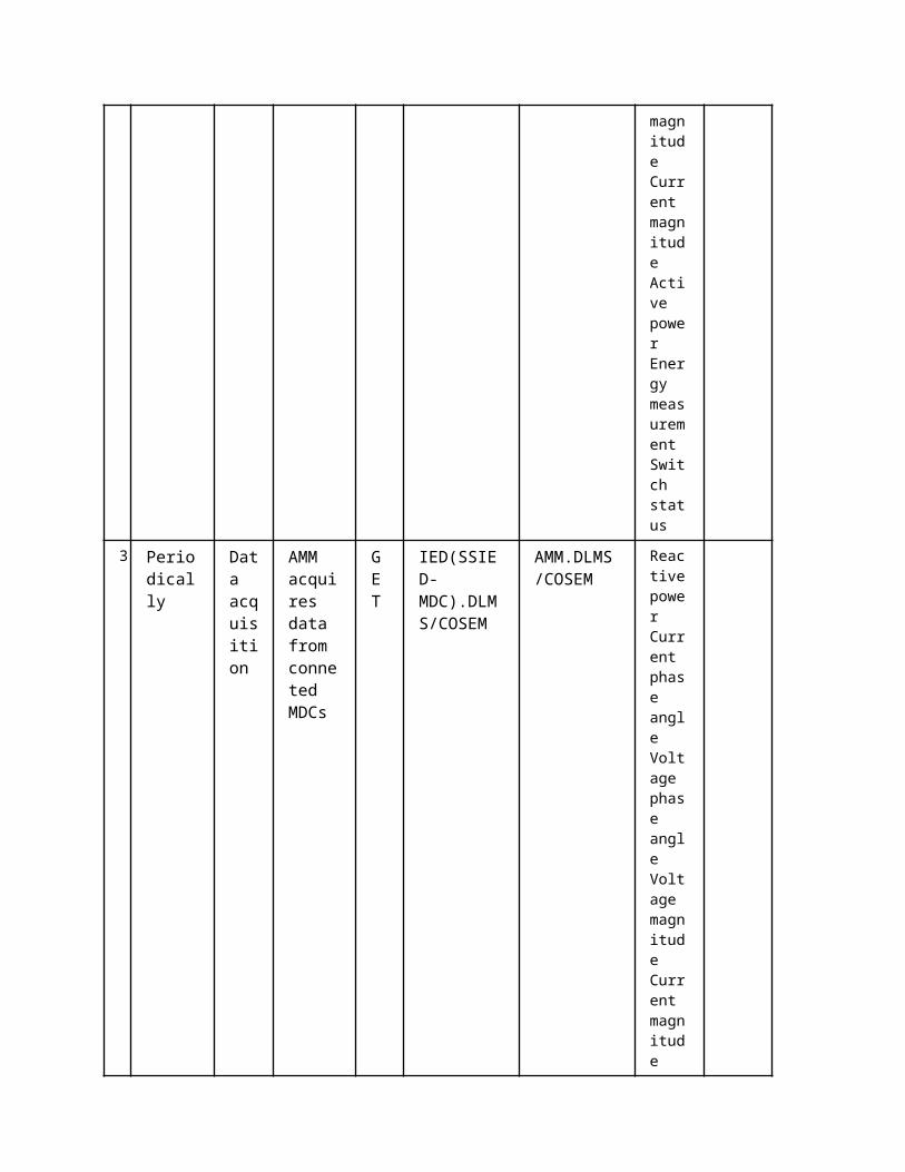
1
Periodically
Signals acquisition
SM samples sensors signals (voltages and currents) and calculate powers and energies
REPORT Sensor
IED(DIED-SM).functions
Current phase angle Voltage phase angle Voltage magnitude Current magnitude
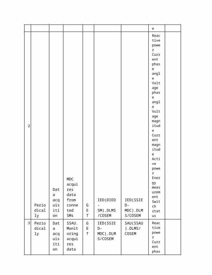
2 Periodically
Data acquisition
MDC acquires data from conneted SMs
GET
IED(DIED-SM).DLMS/COSEM
IED(SSIED-MDC).DLMS/COSEM
Reactive power
Current phase angle Voltage phase angle Voltage magnitude Current magnitude Active power
Energy measurement Switch
status
3
Periodically
Data acquisition
SSAU.Monitoring acquires data from MDC
GET
IED(SSIED-MDC).DLMS/COSEM
SAU(SSAU).DLMS/COSEM
Reactive power
Current phase angle Voltage phase angle Voltage magnitude Current magnitude Active power
Energy measurement Switch status
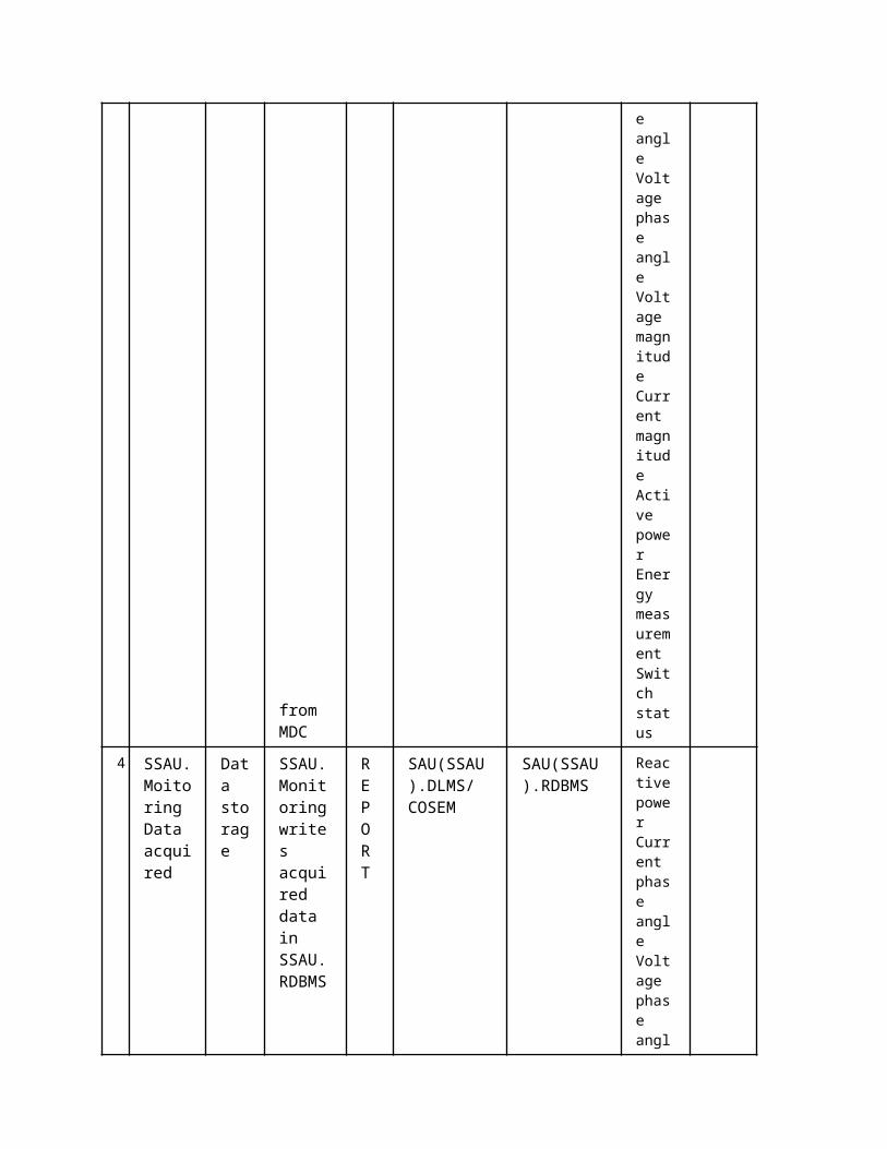
4 SSAU.Moitoring Data acquired
Data storage
SSAU.Monitoring writes acquired data in SSAU.RDBMS
REPORT
SAU(SSAU).DLMS/COSEM
SAU(SSAU).RDBMS
Reactive power
Current phase angle Voltage phase angle Voltage magnitude Current magnitude Active power
Energy measurement Switch status
Scenario Name:Step No.
Event.
Name of Process/ Activity
Description of Process/ Activity.
Service
Information Producer (Actor)
Information Receiver (Actor)
Information Exchanged
Requirements, R-ID
1
Periodically
Signals acquisition
SM samples sensors signals (voltages and currents) and calculate powers and energies
REPORT Sensor
IED(DIED-SM).functions
Current phase angle
Voltage phase angle
Voltage magnitude Current magnitude
2 Periodically
Data acquisition
SSAU.Monitoring acquires values from connected SMs
GET
IED(DIED-SM).DLMS/COSEM
SAU(SSAU).DLMS/COSEM
Reactive power Current phase angle
Voltage phase angle

Voltage magnitude Current magnitude Active power Energy measurement Switch status
3
SSAU.Monitoring data acquired
Data storage
SSAU.Monitoring writes acquired data in SSAU.RDBMS
REPORT
SAU(SSAU).DLMS/COSEM
SAU(SSAU).RDBMS
Reactive power Current phase angle
Voltage phase angle
Voltage magnitude Current magnitude Active power Energy measurement Switch status
Scenario Name:Step No.
Event.
Name of Process/ Activity
Description of Process/ Activity.
Service
Information Producer (Actor)
Information Receiver (Actor)
Information Exchanged
Requirements, R-ID
1
Periodically
Signals acquisition
SM samples sensors signals (voltages and currents) and calculate powers and energies
REPORT Sensor
IED(DIED-SM).functions
Current phase angle
Voltage phase angle
Voltage magnitude Current magnitude
2 Periodically
Data acquisition
MDC acquires data from conneted SMs
GET
IED(DIED-SM).DLMS/COSEM
IED(SSIED-MDC).DLMS/COSEM
Reactive power Current phase angle
Voltage phase angle
Voltage magnitude Current magnitude

Active power Energy measurement Switch status
3
Periodically
Data acquisition
AMM acquires data from conneted MDCs
GET
IED(SSIED-MDC).DLMS/COSEM
AMM.DLMS/COSEM
Reactive power Current phase angle
Voltage phase angle
Voltage magnitude Current magnitude Active power Energy measurement Switch status
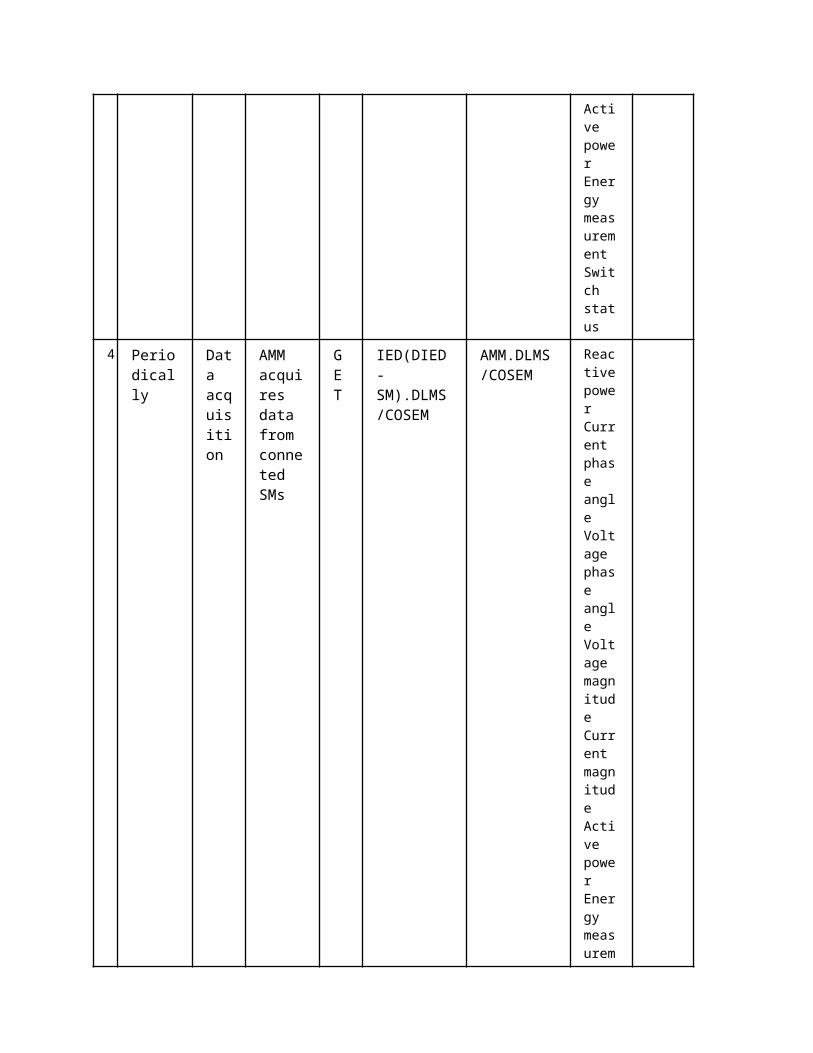
4 Periodically
Data acquisition
AMM acquires data from conneted SMs
GET
IED(DIED-SM).DLMS/COSEM
AMM.DLMS/COSEM
Reactive power Current phas

e angle
Voltage phase angle
Voltage magnitude Current magnitude Active power Energy measurement Switch status
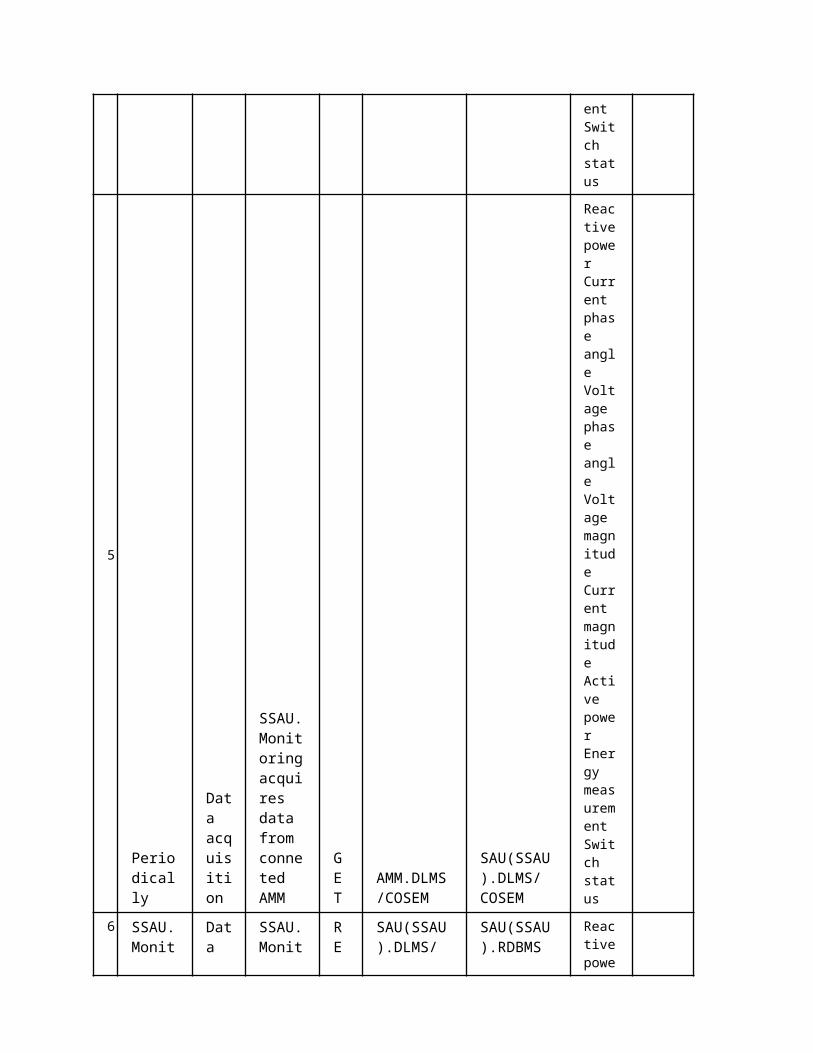
5 Periodically
Data acquisition
SSAU.Monitoring acquires data from conneted AMM
GET
AMM.DLMS/COSEM
SAU(SSAU).DLMS/COSEM
Reactive power Current phase angle
Voltage phase angle
Voltage magnitude Current magnitude Active powe
r Energy measurement Switch status
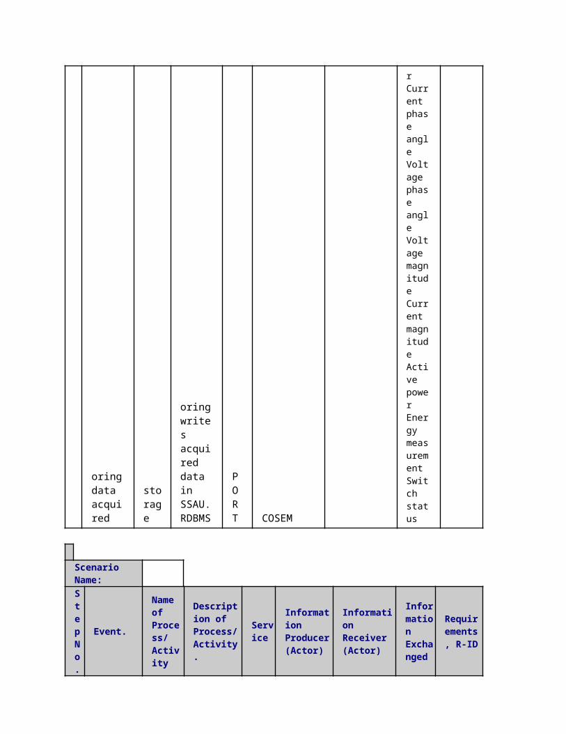
6
SSAU.Monitoring data acquired
Data storage
SSAU.Monitoring writes acquired data in SSAU.RDBMS
REPORT
SAU(SSAU).DLMS/COSEM
SAU(SSAU).RDBMS
Reactive power Current phase angle
Voltage phase angle
Voltage magnitude Current magnitude Active power Energy measurement Switch status
Scenario Name:
Step No.
Event.
Name of Process/ Activity
Description of Process/ Activity.
Service
Information Producer (Actor)
Information Receiver (Actor)
Information Exchanged
Requirements, R-ID
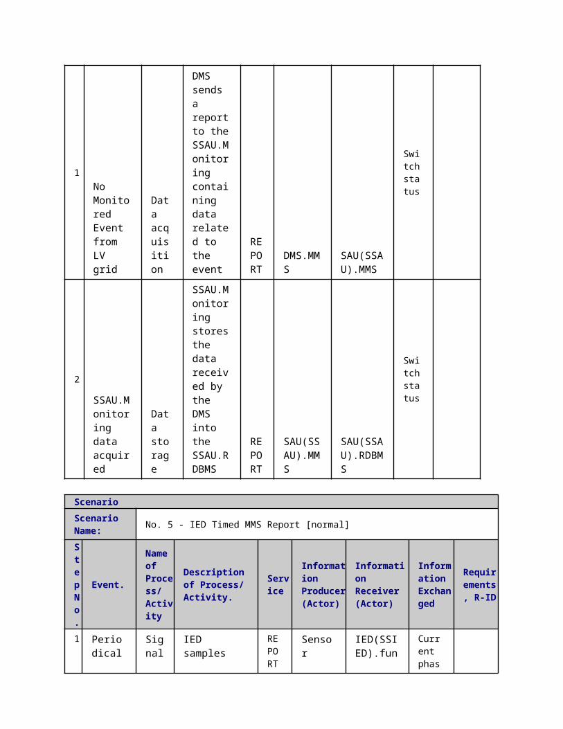
1No Monitored Event from LV grid
Data acquisition
DMS sends a report to the SSAU.Monitoring containing data related to the event
REPORT
DMS.MMS
SAU(SSAU).MMS
Switch status
2
SSAU.Monitoring data acquired
Data storage
SSAU.Monitoring stores the data received by the DMS into the SSAU.RDBMS
REPORT
SAU(SSAU).MMS
SAU(SSAU).RDBMS
Switch status
ScenarioScenario Name: No. 5 - IED Timed MMS Report [normal]
Step No.
Event.
Name of Process/ Activity
Description of Process/ Activity.
Service
Information Producer (Actor)
Information Receiver (Actor)
Information Exchanged
Requirements, R-ID
1
Periodically
Signals acquisition
IED samples and acquires voltages/currents/states/etc. signals from sensors
REPORT Sensor
IED(SSIED).functions
Current phase angle Voltage phase angle Voltage magnitude Current magnitude Switch status

2 Periodically
Data acquisition
IED generates a new report that will be transmitted to the SSAU.Monitoring. Report can contains one or more values
REPORT
SSIED SSAU.DXP.MMS
Voltage magnitude Current magnitude Active power
Energy measurement Switch status
3
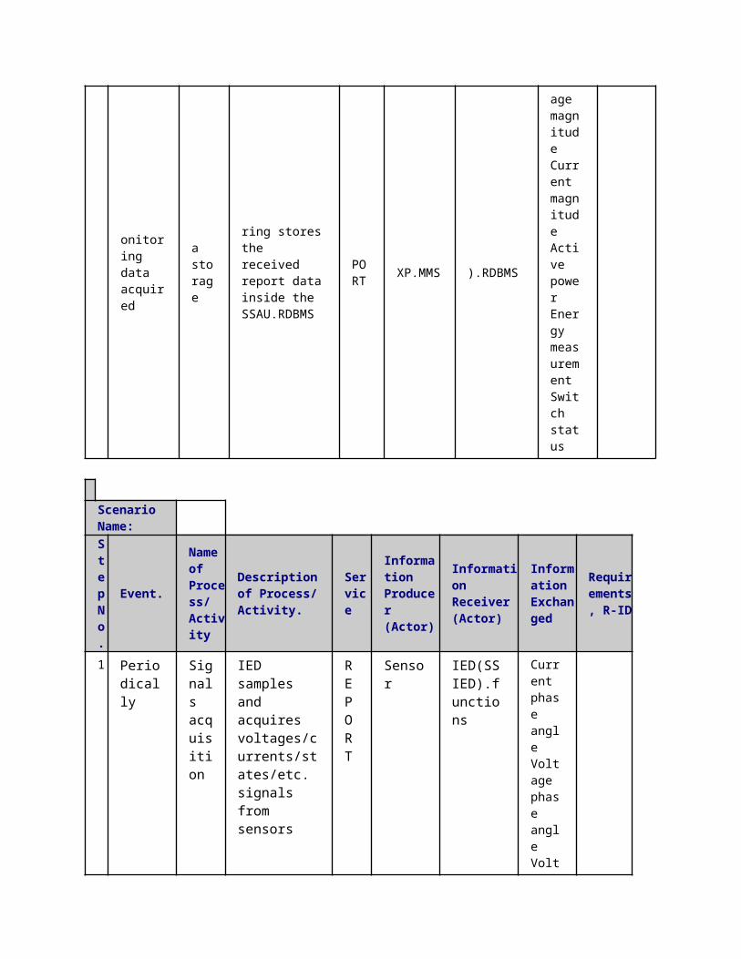
SSAU.Monitoring data acquired
Data storage
SSAU.Monitoring stores the received report data inside the SSAU.RDBMS
REPORT
SSAU.DXP.MMS
SAU(SSAU).RDBMS
Voltage magnitude Current magnitude Active power
Energy measurement Switch status
Scenario Name:Step No.
Event.
Name of Process/ Activity
Description of Process/ Activity.
Service
Information Producer (Actor)
Information Receiver (Actor)
Information Exchanged
Requirements, R-ID
1 Periodically
Signals acquisition
IED samples and acquires voltages/currents/states/etc. signals from
REPORT
Sensor IED(SSIED).functions
Current phase angle Voltage
sensors
phase angle Voltage magnitude Current magnitude Switch status
2
Periodically
Data acquisition
IED generates a new report that will be transmitted to the SSAU.Monitoring. Report can contains one or more values
REPORT
IED(SSIED).MMS
SAU(SSAU).MMS
Reactive power
Current phase angle Voltage phase angle Voltage magnitude Current magnitude Active power
Energy measurement Switch status
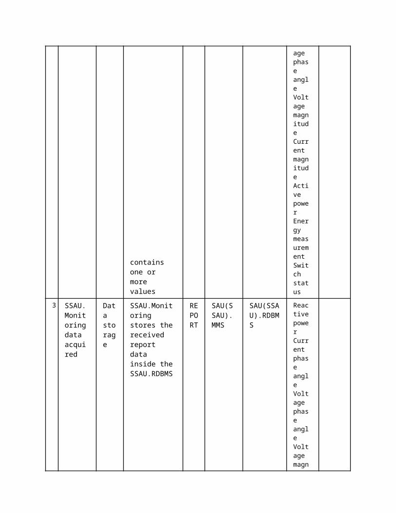
3 SSAU.Monitoring data acquired
Data storage
SSAU.Monitoring stores the received report data inside the SSAU.RDBMS
REPORT
SAU(SSAU).MMS
SAU(SSAU).RDBMS
Reactive power
Current phase angle Voltage phase

angle Voltage magnitude Current magnitude Active power
Energy measurement Switch status
ScenarioScenario Name: No. 7 - IED Read MMS [normal]
Step No.
Event.
Name of Process/ Activity
Description of Process/ Activity.
Service
Information Producer (Actor)
Information Receiver (Actor)
Information Exchanged
Requirements, R-ID
1
Periodically
Signals acquisition
IED samples and acquires voltages/currents/states/etc. signals from sensors
REPORT
SensorIED(SSIED).functions
Current phase angle Voltage phase angle Voltage magnitude Current magnitude Switch status
2 Threshold crossed
Data acquisition
IED generate a new report that will be transmitted to the
REPORT
IED(SSIED).MMS
SAU(SSAU).MMS
Reactive power
Current
SSAU.Monitoring. Report can contains one or more values
phase angle Voltage phase angle Voltage magnitude Current magnitude Active power
Energy measurement Switch status
3
SSAU.Monitoring data acquired
Data storage
SSAU.Monitoring stores the received report data inside the SSAU.RDBMS
REPORT
SAU(SSAU).MMS
SAU(SSAU).RDBMS
Reactive power
Current phase angle Voltage phase angle Voltage magnitude Current magnitude Active power
Energy measurement Switch status
Scenario Name:
Step No.
Event.
Name of Process/ Activity
Description of Process/ Activity.
Service
Information Producer (Actor)
Information Receiver (Actor)
Information Exchanged
Requirements, R-ID
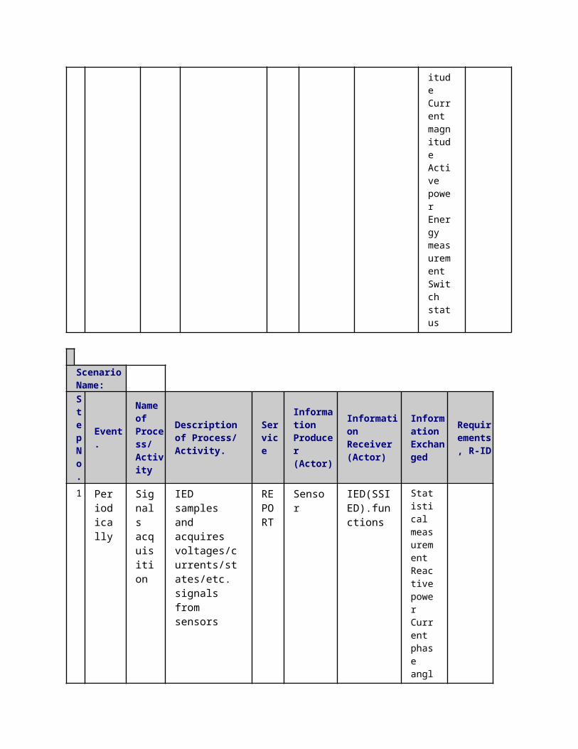
1
Periodically
Signals acquisition
IED samples and acquires voltages/currents/states/etc. signals from sensors
REPORT Sensor
IED(SSIED).functions
Statistical measurement Reactive power
Current phase angle Voltage phase angle Voltage magnitude Current magnitude Active power
Energy measurement Switch status
2 Read request
Data acquisition
SSAU.Monitoring requestes a read then IED answers sending the requested values
GET
IED(SSIED).MMS
SAU(SSAU).MMS
Statistical measurement Reactive power
Current

phase angle Voltage phase angle Voltage magnitude Current magnitude Active power
Energy measurement Switch status
Scenario Name:
Step No.
Event.
Name of Process/ Activity
Description of Process/ Activity.
Service
Information Producer (Actor)
Information Receiver (Actor)
Information Exchanged
Requirements, R-ID
1 Periodically
Data storage
SSAU.Reporting reads data from SSAU.RDBMS
GET SAU(SSAU).RDBMS
SAU(SSAU).MMS
Statistical measurement Reactive power Current phase angle Voltage phase angle Voltage magnitude Current magnitude Active

power Energy measurement Switch status
2
Threshold crossed
Data report
SSAU.Reporting generates a new report if a predefined threshold is crossed
REPORT
SAU(SSAU).MMS
SAU(PSAU).MMS
Statistical measurement Reactive power Current phase angle Voltage phase angle Voltage magnitude Current magnitude Active power Energy measurement Switch status
ScenarioScenario Name: No. 10 - Reporting Read MMS [normal]
Step No.
Event.
Name of Process/ Activity
Description of Process/ Activity.
Service
Information Producer (Actor)
Information Receiver (Actor)
Information Exchanged
Requirements, R-ID
1 Read request from external entity
Data acquisition
SSAU.Reporting receives a read data request from an external entity so it retrieves
GET
SAU(SSAU).RDBMS
SAU(SSAU). MMS SAU(SSAU). Modbus SAU(SSAU).IEC104
Statistical measurement Reactive power
Current phase angle Voltage phase angle

data from SSAU.RDBMS
Voltage magnitude Current magnitude Active power Energy measurement Switch status
Scenario Name:
Step No.
Event.
Name of Process/ Activity
Description of Process/ Activity.
Service
Information Producer (Actor)
Information Receiver (Actor)
Information Exchanged
Requirements, R-ID
1
Periodically
Data storage
SSAU.Reporting retrieves data required to calculate new statical values (such as min, max, avg, etc.) GET
SAU(SSAU).RDBMS
SAU(SSAU).Functions
Voltage magnitude Current magnitude Active power Energy measurement
Switch status
2 Data retrieved
Statistical calculation
SSAU.Reporting calculates a set of statistical values
EXECUTE
SAU(SSAU).Functions
SAU(SSAU).Functions
Reactive power Current phase angle Voltage phase angle Voltage

magnitude Current magnitude Active power Energy measurement
Switch status
3
Statistical data calculated
Data storage
SSAU.Reporting stores the calculated statical data inside the SSAU.RDBMS
REPORT
SAU(SSAU).Functions
SAU(SSAU).RDBMS
Statistical measurement
5 Information ExchangedInformation ExchangedName of Information (ID)
Description of Information Exchanged Requirements to information data
Statistical measurement
Statistical values such as min, max, avg, std, etc.
Reactive power Reactive power injection [VAr]
Current phase angle Current phase angle [rad]
Voltage phase angle Voltage phase angle [rad]
Voltage magnitude Voltage magnitude [V]
Current magnitude Current magnitude [A]
Active power Active power injection [W]
Energy measurement Energy measurement [Wh]
Switch status Information about devices states (i.e. breaker: open, close, undefined; tap
changer position; etc.)
1 Description of the Use Case1.1 Name of the Use Case
Use Case Identification
IDArea / Domain(s)/Zone(s)
Name of the Use Case
161 Distribution grid dynamic monitoring for providing dynamic information to TSOs
1.2 Version ManagementVersion Management
1.3 Scope and Objectives of Use CaseScope and Objectives of Use Case
Scope
Defining monitoring applications and algorithms that can provide “dynamics†information for TSOs. The business case sought here is to �manage the new complexity and inter-dependence between electric power transmission and distribution systems to support a long-term sustainable energy system.
Objective(s)Manage the new complexity and inter-dependence between electric power transmission and distribution systems to support a long-term sustainable energy system.
Related businesscase(s)
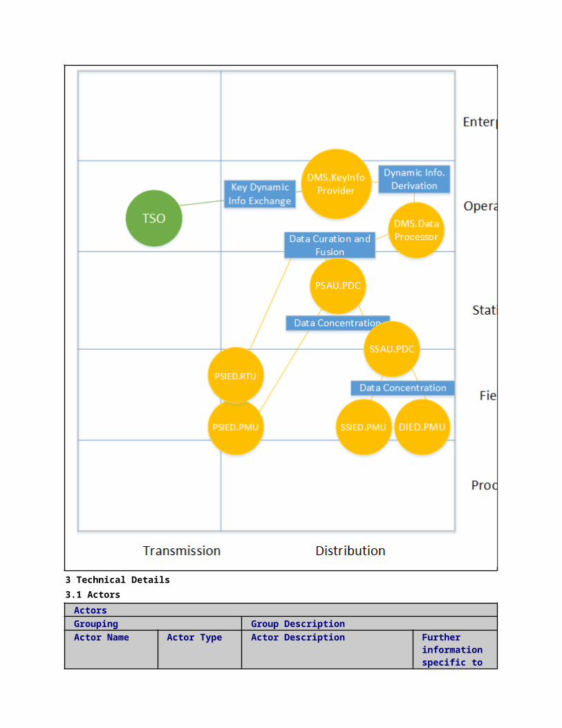
1.4 Narrative of Use CaseNarrative of Use CaseShort descriptionUtilizing time-stamped PMU data and discrete traditional measurements for providing “dynamics” information on distribution grid operation to TSOs.Complete descriptionThe paradigm shift towards Smart Grids requires a tighter integration of the operation of transmission grids (HV) with distribution grids (MV and LV). Coupling the use of PMU data from both the HV grid and MV and LV grids coherently with advanced communication protocols for can allow for a tighter interaction between transmission and distribution. To this aim, key information exchange of specific distribution network dynamics to the transmission system operator is considered in this use case.The monitoring algorithms receive inputs of time-stamped PMU data and discrete traditional measurements and outputs “dynamics” information on distribution grid operation to TSOs.The algorithms sits in the primary substation.
1.5 General RemarksGeneral Remarks
2 Diagrams of Use Case
3 Technical Details3.1 Actors
ActorsGrouping Group Description
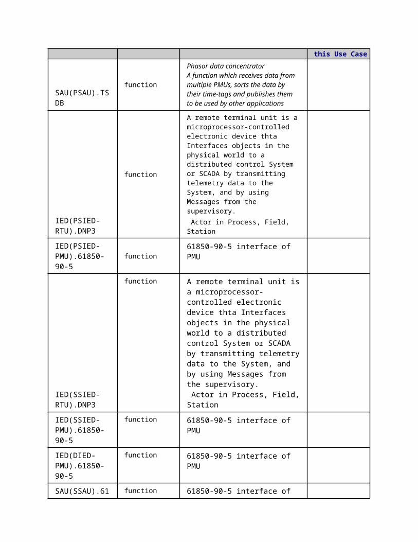
Actor Name Actor Type Actor DescriptionFurther information specific to this Use Case
SAU(PSAU).TSDB
function
Phasor data concentratorA function which receives data from multiple PMUs, sorts the data by their time-tags and publishes them to be used by other applications
IED(PSIED-RTU).DNP3
function
A remote terminal unit is a microprocessor-controlled electronic device thta Interfaces objects in the physical world to a distributed control System or SCADA by transmitting telemetry data to the System, and by using Messages from the supervisory. Actor in Process, Field, Station
IED(PSIED-PMU).61850-90-5
function 61850-90-5 interface of PMU
IED(SSIED-RTU).DNP3
function A remote terminal unit is a microprocessor-controlled electronic device thta Interfaces objects in the physical world to a distributed control System or SCADA by transmitting telemetry data to the System, and by using Messages from the supervisory. Actor in Process, Field, Station
IED(SSIED-PMU).61850-90-5
function 61850-90-5 interface of PMU
IED(DIED-PMU).61850-90-5
function 61850-90-5 interface of PMU
SAU(SSAU).61850-90-5
function61850-90-5 interface of SAU
SAU(PSAU).61850-90-5
function61850-90-5 interface of SAU
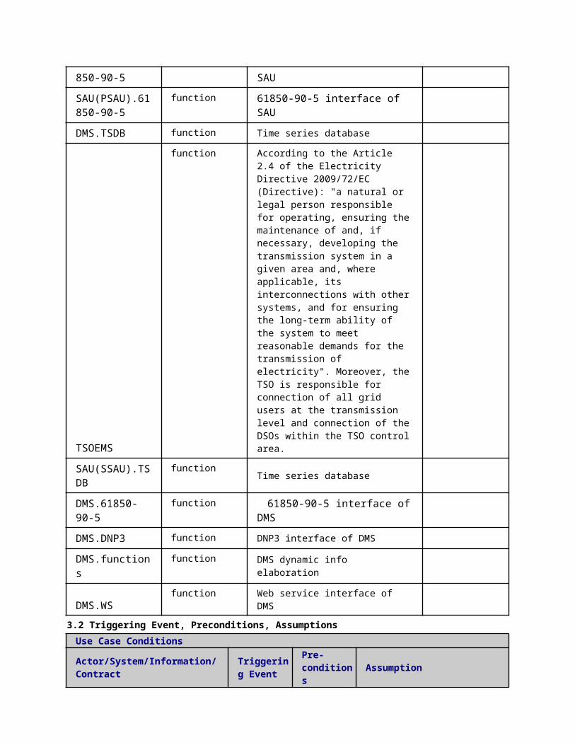
DMS.TSDB function Time series database
TSOEMS function According to the Article 2.4 of the Electricity Directive 2009/72/EC (Directive): "a natural or legal person responsible for operating, ensuring the maintenance of and, if necessary, developing the transmission system in a given area and, where applicable, its interconnections with other systems, and for ensuring the long-term ability of the system to meet reasonable demands for the transmission of electricity". Moreover, the TSO is responsible for connection of all grid
users at the transmission level and connection of the DSOs within the TSO control area.
SAU(SSAU).TSDB function Time series database
DMS.61850-90-5 function 61850-90-5 interface of DMS
DMS.DNP3 function DNP3 interface of DMS
DMS.functions function DMS dynamic info elaboration
DMS.WS function Web service interface of DMS
3.2 Triggering Event, Preconditions, AssumptionsUse Case ConditionsActor/System/Information/Contract
Triggering Event
Pre-conditions Assumption
3.3 ReferencesReferences
No. References Type Reference Statu
sImpact on Use Case
Organistaor / Organisation
Link
3.4 Further Information to the Use Case for Classification / MappingClassification InformationRelation to Other Use CasesLevel of DepthDetailedPriorisationGeneric, Regional or National RelationGenericViewpointTechnicalFurther Keyword for ClassificationPMU, dynamics monitoring
4 Step by Step Analysis of Use Case4.1 Overview of Scenarios
Scenario ConditionsNo.
Scenario Name Primary Actor Triggering Event Pre-Condition Post-Condition
4.2 Steps - ScenariosScenarioScenario Name: No. 1 - Transmitting traditional measurements from RTU to DMS via DNP3
Step No.
Event.Name of Process/ Activity
Description of Process/ Activity.
ServiceInformation Producer (Actor)
Information Receiver (Actor)
Information Exchanged
Requirements, R-ID
1 DMS polling
Data acquisition
DMS sends a request
EXECUTE
DMS.DNP3
IED(PSIED-RTU).D
Voltage magnitude Current

to RTU to collect data
NP3IED(SIED-RTU).DNP3
magnitude Frequency measurement Current phase angle Voltage phase angle
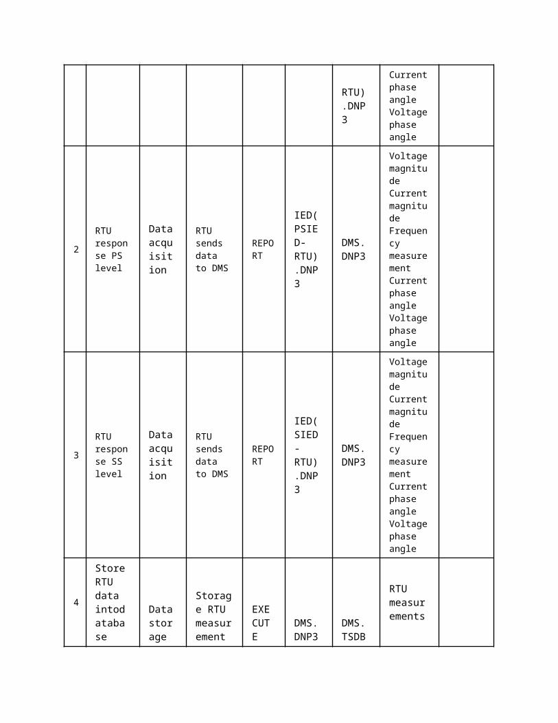
2
RTU response PS level
Data acquisition
RTU sends data to DMS
REPORT
IED(PSIED-RTU).DNP3
DMS.DNP3
Voltage magnitude Current magnitude Frequency measurement Current phase angle Voltage phase angle
3
RTU response SS level
Data acquisition
RTU sends data to DMS
REPORT
IED(SIED-RTU).DNP3
DMS.DNP3
Voltage magnitude Current magnitude Frequency measurement Current phase angle Voltage phase angle
4
Store RTU data intodatabase
Data storage
Storage RTU measurement
EXECUTE
DMS.DNP3
DMS.TSDB
RTU measurements
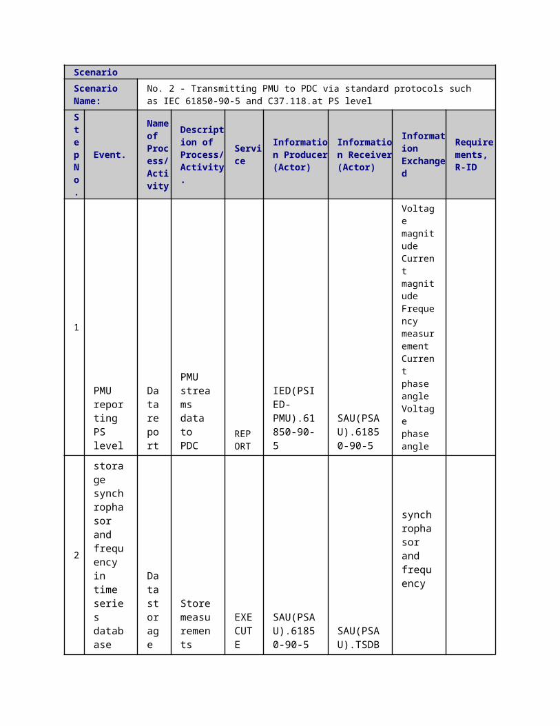
ScenarioScenario Name:
No. 2 - Transmitting PMU to PDC via standard protocols such as IEC 61850-90-5 and C37.118.at PS level
Step No.
Event.
Name of Process/ Activity
Description of Process/ Activity.
Service
Information Producer (Actor)
Information Receiver (Actor)
Information Exchanged
Requirements, R-ID
1
PMU reporting PS level
Data report
PMU streams data to PDC
REPORT
IED(PSIED-PMU).61850-90-5
SAU(PSAU).61850-90-5
Voltage magnitude Current magnitude Frequency measurement Current phase angle Voltage phase angle
2
storage synchrophasor and frequency in time series database
Data storage
Store measurements
EXECUTE
SAU(PSAU).61850-90-5
SAU(PSAU).TSDB
synchrophasor and frequency
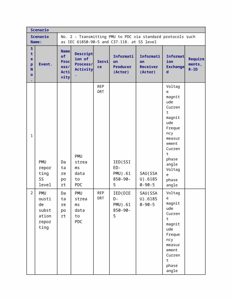
ScenarioScenario Name:
No. 2 - Transmitting PMU to PDC via standard protocols such as IEC 61850-90-5 and C37.118. at SS level
Step No.
Event.
Name of Process/ Activity
Description of Process/ Activity.
Service
Information Producer (Actor)
Information Receiver (Actor)
Information Exchanged
Requirements, R-ID
1 PMU reporting SS level
Data report
PMU streams data to PDC
REPORT
IED(SSIED-PMU).61850-90-5
SAU(SSAU).61850-90-5
Voltage magnitude Current magnitude Frequency measurement Current

phase angle Voltage phase angle
2
PMU oustide substation reporting
Data report
PMU streams data to PDC
REPORT
IED(DIED-PMU).61850-90-5
SAU(SSAU).61850-90-5
Voltage magnitude Current magnitude Frequency measurement Current phase angle Voltage phase angle
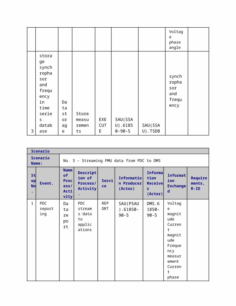
3
storage synchrophasor and frequency in time series database
Data storage
Store measurements
EXECUTE
SAU(SSAU).61850-90-5
SAU(SSAU).TSDB
synchrophasor and frequency
ScenarioScenario Name: No. 3 - Streaming PMU data from PDC to DMS
Step No.
Event.
Name of Process/ Activity
Description of Process/ Activity.
Service
Information Producer (Actor)
Information Receiver (Actor)
Information Exchanged
Requirements, R-ID
1 PDC reporting
Data report
PDC streams data to applications
REPORT
SAU(PSAU).61850-90-5
DMS.61850-90-5
Voltage magnitude Current magnitude Frequency measurement

Current phase angle Voltage phase angle
2PDC reporting SS to PS
Data report
PDC streams data to applications
REPORT
SAU(SSAU).61850-90-5
DMS.61850-90-5
Voltage magnitude Current magnitude Frequency measurement Current phase angle Voltage phase angle
3
PDC stores the measurements
Data storage
Store measurements
EXECUTE
DMS.61850-90-5
DMS.TSDB
synchrophasor and frequency
ScenarioScenario Name: No. 4 - Extracting key information
Step No.
Event.
Name of Process/ Activity
Description of Process/ Activity.
Service
Information Producer (Actor)
Information Receiver (Actor)
Information Exchanged
Requirements, R-ID
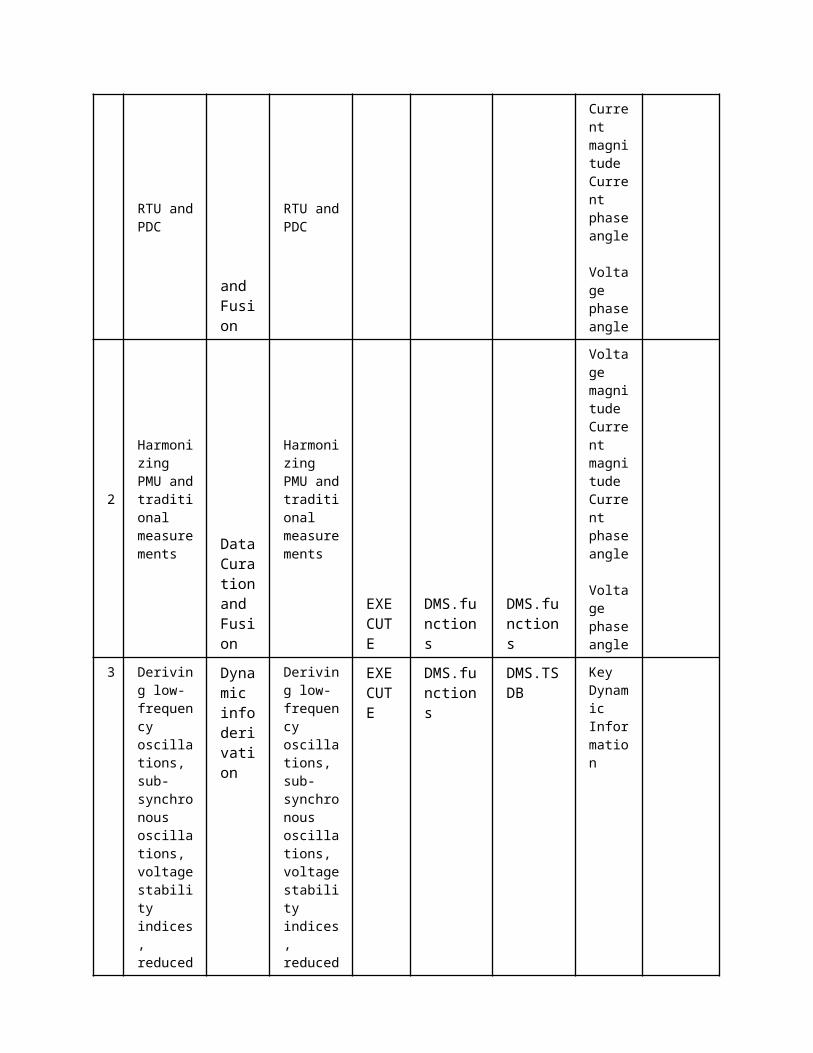
1
Bad data handling of RTU and PDC Data
Curation and Fusion
Bad data handling of RTU and PDC
EXECUTE
DMS.TSDB
DMS.functions
Voltage magnitude Current magnitude Current phase angle Voltage phase angle

2
Harmonizing PMU and traditional measurements
Data Curation and Fusion
Harmonizing PMU and traditional measurements
EXECUTE
DMS.functions
DMS.functions
Voltage magnitude Current magnitude Current phase angle Voltage phase angle
3
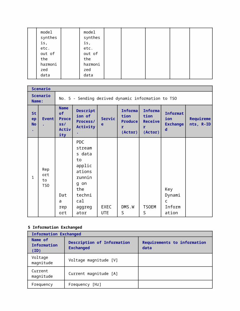
Deriving low-frequency oscillations, sub-synchronous oscillations, voltage stability indices, reduced model synthesis, etc. out of the harmonized data
Dynamic info derivation
Deriving low-frequency oscillations, sub-synchronous oscillations, voltage stability indices, reduced model synthesis, etc. out of the harmonized data
EXECUTE
DMS.functions
DMS.TSDB
Key Dynamic Information
ScenarioScenario Name: No. 5 - Sending derived dynamic information to TSO
Step No.
Event.
Name of Process/ Activity
Description of Process/ Activity.
ServiceInformation Producer (Actor)
Information Receiver (Actor)
Information Exchanged
Requirements, R-ID
1 Report to TSO
Data report
PDC streams data to applications running on the
EXECUTE
DMS.WS
TSOEMS
Key Dynamic Information
technical aggregator
5 Information ExchangedInformation ExchangedName of Information (ID)
Description of Information Exchanged Requirements to information data
Voltage magnitude Voltage magnitude [V]
Current magnitude Current magnitude [A]
Frequency measurement Frequency [Hz]
Key Dynamic Information
This information includes all dynamic data to be sent to TSO including:1. Steady state model synthesis of distribution system2. Modes of the distribution systems together with indices indicating how stable the distribution system is in terms of dynamic stability3. Indices showing how stable the distribution system is in terms of voltage stability4. Indicators of sub-synchronous oscillations
Current phase angle Current phase angle [rad]
Voltage phase angle Voltage phase angle [rad]
6 Requirements (optional)Requirements (optional)
7 Common Terms and DefinitionsCommon Terms and DefinitionsTerm Definition
8 Custom Information (optional)Custom Information (optional)Key Value Refers to Section
1 Description of the Use Case1.1 Name of the Use Case
Use Case Identification
IDArea / Domain(s)/Zone(s)
Name of the Use Case
133 Real-Time Medium Voltage Network State Estimation (MVSE)
1.2 Version ManagementVersion ManagementFrom V1.0 15.12.2014 Antti MutanenAdded the word "Real-Time" to the title to be consistant with the LVSE use case.
2015-04-10Fannar ThordarsonMade changes according to the latest updates from Antti (available on wiki from 2015-04-02)
1.3 Scope and Objectives of Use CaseScope and Objectives of Use CaseScope
Objective(s)The objective of the real-time PSAU.SE is to obtain the best possible estimate for the MV network state. The state estimation task has been divided into two parts; MV and LV network estimation. This use case considers only the MV network state estimation.
Related businesscase(s)
1.4 Narrative of Use CaseNarrative of Use CaseShort descriptionThe medium voltage state estimator (PSAU.SE) combines all the available measurement information and calculates the most likely state of the network. State estimates are calculated for present time (t=0) using the newest available input data. PSAU.SE calculation will run an intelligent device located either on a primary substation or in a control center. Real-time PSAU.SE is a secondary function serving primary functions (e.g. medium voltage network power control, PSAU.PC) and will be run based on primary function needs (on-demand or periodically). The input data includes the real-time measurements for the load, production and line flows, load estimates for unmeasured loads, and the network topology. Output will be the network state described with node voltages, line current flows, and node power injection values.Complete descriptionA PSAU.SE algorithm is developed, that can be utilized for estimating the present states in a medium voltage network. The algorithm will be a branch current based weighted least squares estimator. Medium voltage network states; node voltages, line current flows and line power flows are calculated for all three phases. For a normal MV feeder, the computing time will be some tens of milliseconds and the overall execution time will depend on the number and size of the feeders. The basic steps in real-time PSAU.SE are as follows (in normal operation conditions):
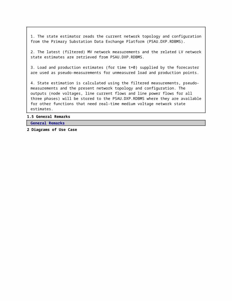
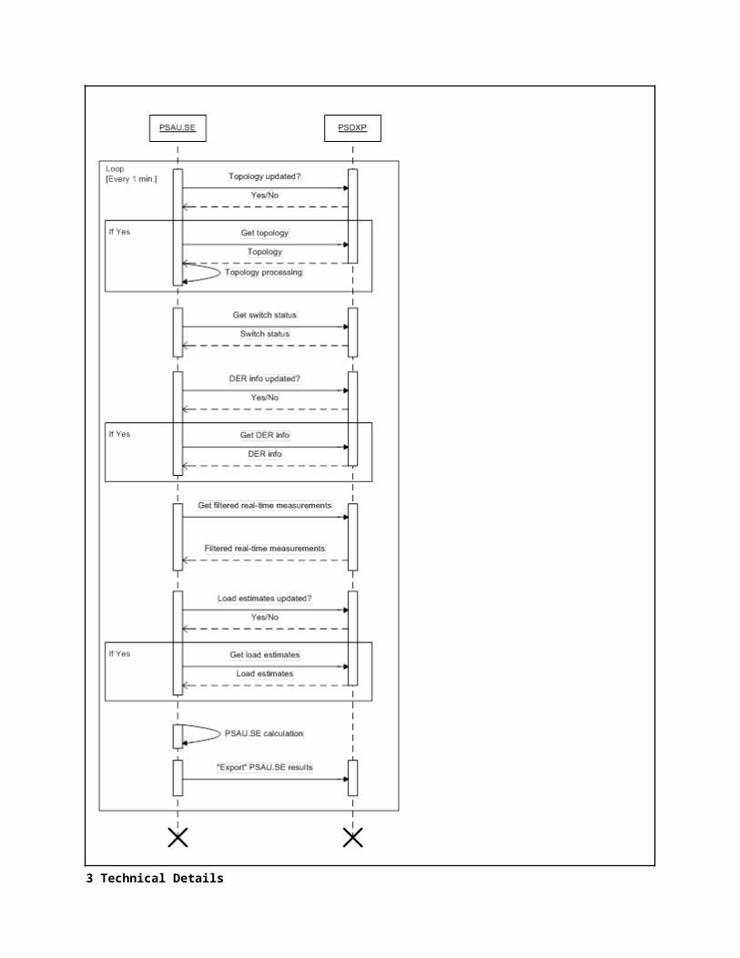
1. The state estimator reads the current network topology and configuration from the Primary Substation Data Exchange Platform (PSAU.DXP.RDBMS).
2. The latest (filtered) MV network measurements and the related LV network state estimates are retrieved from PSAU.DXP.RDBMS.
3. Load and production estimates (for time t=0) supplied by the forecaster are used as pseudo-measurements for unmeasured load and production points.
4. State estimation is calculated using the filtered measurements, pseudo-measurements and the present network topology and configuration. The outputs (node voltages, line current flows and line power flows for all three phases) will be stored to the PSAU.DXP.RDBMS where they are available for other functions that need real-time medium voltage network state estimates.
1.5 General Remarks
General Remarks2 Diagrams of Use Case
3 Technical Details
3.1 ActorsActorsGrouping Group Description
Actor Name Actor Type Actor DescriptionFurther information specific to this Use Case
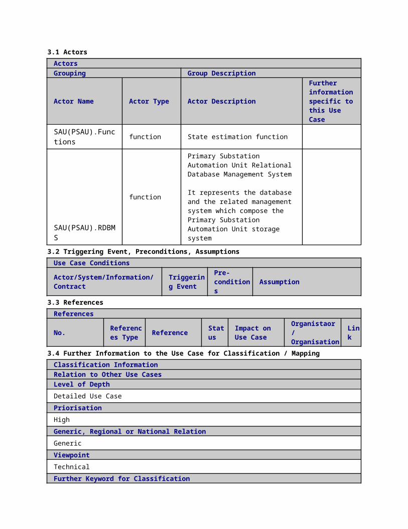
SAU(PSAU).Functions
function State estimation function
SAU(PSAU).RDBMS
function
Primary Substation Automation Unit Relational Database Management System It represents the database and the related management system which compose the Primary Substation Automation Unit storage system
3.2 Triggering Event, Preconditions, AssumptionsUse Case ConditionsActor/System/Information/Contract
Triggering Event
Pre-conditions Assumption
3.3 ReferencesReferences
No. References Type Reference Statu
sImpact on Use Case
Organistaor / Organisation
Link
3.4 Further Information to the Use Case for Classification / MappingClassification InformationRelation to Other Use CasesLevel of DepthDetailed Use CasePriorisationHighGeneric, Regional or National RelationGenericViewpointTechnicalFurther Keyword for ClassificationState Estimation; Real-Time; Distribution Network
4 Step by Step Analysis of Use Case4.1 Overview of Scenarios
Scenario ConditionsNo.
Scenario Name Primary Actor Triggering Event Pre-Condition Post-Condition
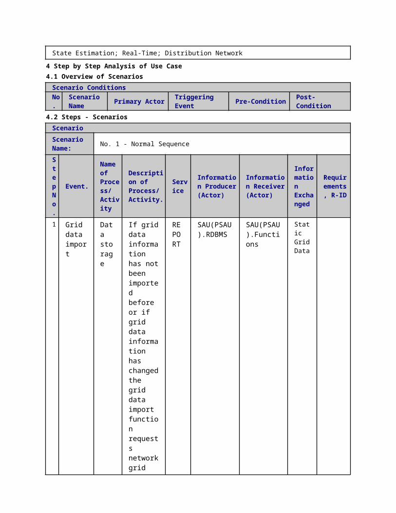
4.2 Steps - ScenariosScenarioScenario Name: No. 1 - Normal Sequence
St Event. Name Description Servi Information Information Inform Require
ep No.
of Process/ Activity
of Process/ Activity. ce Producer
(Actor)Receiver (Actor)
ation Exchanged
ments, R-ID
1
Grid data import
Data storage
If grid data information has not been imported before or if grid data information has changed the grid data import function requests network grid data information from the PSAU.DXP.RDBMS.
REPORT
SAU(PSAU).RDBMS
SAU(PSAU).Functions
Static Grid Data
3
Switch status import
Data storage
Switch status import function requests the latest switch and fuse status information from the MV DXP.
REPORT
SAU(PSAU).RDBMS
SAU(PSAU).Functions
Switch and Fuse status
4 DER information import
Data storage
If DER information has not been imported before or
REPORT
SAU(PSAU).RDBMS
SAU(PSAU).Functions
Customer information Der infor
if it has changed the information regarding customers, generators, capacitors etc. is requested from the MV DXP
mation
5
Real-time measurement reading
Data storage
Real-time measurements (RTU and smart meter measurements) are requested from the PSAU.DXP.RDBMS.
REPORT
SAU(PSAU).RDBMS
SAU(PSAU).Functions
Reactive power Current phase angle
Voltage phase angle
Active power Current magnitude Voltage magnitude
6 Load Estimate Import
Data storage
If load and production estimates have not been
REPORT
SAU(PSAU).RDBMS
SAU(PSAU).Functions
long term load and production forec
imported before or if they have changed, the load and production estimates are requested from the MV DXP.
ast short term load and production forecast
7
PSAU state estimation execution
State estimation
Calculate the state of the network
EXECUTE
SAU(PSAU).Functions
SAU(PSAU).Functions
Reactive power Current phase angle
Voltage phase angle
Active power Current magnitude Voltage magnitude
8 Export PSAU.SE results
Data storage
The results from PSAU.SE are exported to PSAU.DXP
REPORT
SAU(PSAU).Functions
SAU(PSAU).RDBMS
Reactive power Current phase angle

.RDBMS.
Voltage phase angle
Active power Current magnitude Voltage magnitude
ScenarioScenario Name: No. 2 - Convergence issues
Step No.
Event.
Name of Process/ Activity
Description of Process/ Activity.
Service
Information Producer (Actor)
Information Receiver (Actor)
Information Exchanged
Requirements, R-ID
7.1
Detection non-convergence
detect error
Remove the most likely source of non-convergence. The Largest Normalized Residual Test is used to decide which real-time measur
EXECUTE
SAU(PSAU).Functions
SAU(PSAU).Functions
algorithm performance index
ement is removed from input set.
7.2
Possible source removed
detect error
Recalculated PSAU.SE and re-evaluate convergence.
EXECUTE
SAU(PSAU).Functions
SAU(PSAU).Functions
algorithm performance index
7.2.1
MVSE converged
detect error
If convergence is achieved, continue to step 8 in the Normal Sequence and set the status flag to "executed, but with limited accuracy".
EXECUTE
SAU(PSAU).Functions
SAU(PSAU).Functions
algorithm performance index
ScenarioScenario Name: No. 3 - Gross error in Real-time measurements
Step No.
Event.
Name of Process/ Activity
Description of Process/ Activity.
Service
Information Producer (Actor)
Information Receiver (Actor)
Information Exchanged
Requirements, R-ID

5.1.1
Gross error in MVSE Real-time measurements removal
detect error
Gross error occurs as the real-time measurements are imported to PSAU.SE
REPORT
SAU(PSAU).RDBMS
SAU(PSAU).Functions
Current phase angle Voltage phase angle Active power Current magnitude Voltage magnitude
5.1.2
Erroneous measurements removed
detect error
Remove the erroneous data and proceed to step 6 in the normal sequence. Set the satus flag to "executed, but with limited accuracy.
EXECUTE
SAU(PSAU).Functions
SAU(PSAU).Functions
algorithm performance index
5.1.3
Erroneous measurements removed
detect error
Remove the erroneous data and proceed to step 6 in the normal sequence. Set the
EXECUTE
SAU(PSAU).Functions
SAU(PSAU).RDBMS
algorithm performance index
satus flag to "executed, but with limited accuracy.
ScenarioScenario Name: No. 4 - Gross error in load/production data
Step No.
Event.
Name of Process/ Activity
Description of Process/ Activity.
Service
Information Producer (Actor)
Information Receiver (Actor)
Information Exchanged
Requirements, R-ID
6.1
Gross error in MVSE load and production data
detect error
Gross error occurs as the load and production data are imported to PSAU.SE
REPORT
SAU(PSAU).Functions
SAU(PSAU).Functions
algorithm performance index
5.2
Erroneous data removed
detect error
Remove the erroneous data and proceed to step 7 in the normal sequence. Set
EXECUTE
SAU(PSAU).Functions
SAU(PSAU).Functions
algorithm performance index
the satus flag to "executed, but with limited accuracy.
ScenarioScenario Name: No. 5 - Voltage measurement missing
Step No.
Event.Name of Process/ Activity
Description of Process/ Activity.
Service
Information Producer (Actor)
Information Receiver (Actor)
Information Exchanged
Requirements, R-ID
5.2
Voltage measurements (connection to LV) missing
Missing data
PSAU.SE doesn't receive voltage measurements and, thus, cannot be executed. Set the status flag to "error, execution not possible".
CANCEL
SAU(PSAU).Functions
SAU(PSAU).RDBMS
algorithm performance index
5.3
Quality index estimation update
algorithm performance index
PSAU.SE doesn't receive voltage measurements and,
CHANGE
SAU(PSAU).Functions
SAU(PSAU).RDBMS
algorithm performance index
thus, cannot be executed. Set the status flag to "error, execution not possible".
ScenarioScenario Name: No. 6 - Real-time measurements missing
Step No.
Event.
Name of Process/ Activity
Description of Process/ Activity.
Service
Information Producer (Actor)
Information Receiver (Actor)
Information Exchanged
Requirements, R-ID
5.3
Real-time measurements missing
Missing data
If real-time measurements (some or all) are missing, use load and production estimates (pseudo measurements) instead. Continue to step 6 in the normal sequence and
EXECUTE
SAU(PSAU).Functions
SAU(PSAU).Functions
algorithm performance index

set the status flag to "executed, but with limited accuray".
5.4
Quality indexestimation update
algorithm performance index
If real-time measurements (some or all) are missing, use load and production estimates (pseudo measurements) instead. Continue to step 6 in the normal sequence and set the status flag to "executed, but with limited accuray".
CHANGE
SAU(PSAU).Functions
SAU(PSAU).RDBMS
algorithm performance index
ScenarioScenario Name: No. 7 - Pseudo measurements missing
Step No.
Event.Name of Process/ Activity
Description of Process/ Activity.
Service
Information Producer (Actor)
Information Receiver (Actor)
Information Exchanged
Requirements, R-ID
5.4
Pseudo measurements missing
Missing data
If load and production estimates and some or all secondary substation measurements are missing, but real-time primary substation measurements exist, the PSAU.SE is "executed, but with very limited accuracy". This can be achieved by distributing the measured load to load and
EXECUTE
SAU(PSAU).Functions
SAU(PSAU).Functions
algorithm performance index
production points in relation to transformer and DG nominal powers.
5.5
Quality indexestimation update
algorithm performance index
If load and production estimates and some or all secondary substation measurements are missing, but real-time primary substation measurements exist, the PSAU.SE is "executed, but with very limited accuracy". This
CHANGE
SAU(PSAU).Functions
SAU(PSAU).Functions
algorithm performance index
can be achieved by distributing the measured load to load and production points in relation to transformer and DG nominal powers.
ScenarioScenario Name: No. 8 - Measurements not available
Step No.
Event.Name of Process/ Activity
Description of Process/ Activity.
Service
Information Producer (Actor)
Information Receiver (Actor)
Information Exchanged
Requirements, R-ID
5.5
No measurements available
Missing data
In all real-time and pseudo measurements are missing, PSAU.SE cannot be executed. Set the
CANCEL
SAU(PSAU).RDBMS
SAU(PSAU).Functions
algorithm performance index
status flag to "error, execution not possible"
5.6
Quality indexestimation update
algorithm performance index
In all real-time and pseudo measurements are missing, PSAU.SE cannot be executed. Set the status flag to "error, execution not possible"
CHANGE
SAU(PSAU).Functions
SAU(PSAU).RDBMS
algorithm performance index
5 Information ExchangedInformation ExchangedName of Information (ID)
Description of Information Exchanged Requirements to information data
Customer information
Nominal powerPower limitsType of customerConnection pointPhases connected (in case to which phase)
Reactive power Reactive power injection [VAr]
Current phase angle Current phase angle [rad]
Quality index Quality index of state estimation. Could be a number between 0 and 5

or a string
Voltage phase angle Voltage phase angle [rad]
long term load and production forecast
Valid for the next 24 hours
State Estimation results node voltages, line currents etc.
short term load and production forecast
Load and Production Estimates on 10 minutes time range
Static Grid Data
Data exchanged:- Line parameters (R, X, B, G)- Line connections- Location of swithes, breakers and fuses- Transformer parameters
Switch and Fuse status
Der information
Nominal powerPower limitsType of DERConnection pointPhases connected (in case to which phase)
Active power Active power injection [W]
Current magnitude Current magnitude [A]
Voltage magnitude Voltage magnitude [V]
1 Description of the Use Case1.1 Name of the Use Case
Use Case Identification
IDArea / Domain(s)/Zone(s)
Name of the Use Case
134 Real-Time Low Voltage Network State Estimation (LVSE)
1.2 Version ManagementVersion ManagementFrom V1.0 15.12.2014 Antti Mutanen
Modified by adding step 8 ß 12 to scenario 1.
15-04-14 Fannar ThordarsonUC updated according to latest updates from Antti (available on wiki-page on 2/4/2015)
1.3 Scope and Objectives of Use Case
Scope and Objectives of Use CaseScope
Objective(s)The objective of the real-time SSAU.SE is to obtain the best possible estimate for the LV network state. The state estimation task has been divided into two parts; MV and LV network estimation. This use case considers only the LV network state estimation.
Related businesscase(s)
1.4 Narrative of Use CaseNarrative of Use CaseShort descriptionThe state estimator combines all the available measurement information and calculates the most likely state of the network. State estimates are calculated for present time (t=0) using the newest available input data. SSAU.SE calculation will run on an intelligent device located on a secondary substation. Real-time SSAU.SE is a secondary function serving primary functions (e.g. low voltage network power control, SSAU.PC) and will be run based on primary function needs (on-demand or periodically). The input data includes the real-time measurements for the load, production and line flows, load estimates for unmeasured loads, and the network topology. Output will be the network state described with node voltages, line current flows, and node power injection values.Complete descriptionA SSAU.SE algorithm is developed that can be utilized on-demand for estimating the present states in a low voltage grid. SSAU.SE calculation is done in a decentralized manner where the SSAU.SE algorithm is run in an intelligent device located in the secondary substation. Low voltage network states; node voltages, line current flows and line power flows are estimated for all three phases. Computing time will be some tens of milliseconds or more if network is very large.
Steps in the real-time SSAU.SE are as follows (in normal operation conditions): 1. The state estimator reads the current network topology and configuration from the Data Exchange Platform (SAU(SSAU).RDBMS).
2. The latest measurements are retrieved from the SAU(SSAU).RDBMS: 1) Smart meter measurements (load and production in the network nodes) 2) Remote terminal measurements (Voltages, line flows)
3. Load and production estimates (for time t=0) supplied by the forecaster are used as pseudo-measurements for unmeasured load and production points.
State estimation is calculated using the filtered measurements, pseudo-measurements and the present network topology and configuration. The outputs (node voltages, line current flows and line power flows for all three phases) will be stored to the SAU(SSAU).RDBMS where they are available for other functions that need real-time low voltage network state estimates. Some aggregated results are synchronised also to PSAU.DXP.RDBMS.
1.5 General RemarksGeneral Remarks
2 Diagrams of Use Case
3 Technical Details

3.1 ActorsActorsGrouping Group Description
Actor Name Actor Type Actor DescriptionFurther information specific to this Use Case
SAU(SSAU).Functions
function State estimation function
SAU(SSAU).RDBMS function
Secondary Substation Automation Unit Relational Database Management System It represents the database and the related management system which compose the Secondary Substation Automation Unit storage system
3.2 Triggering Event, Preconditions, AssumptionsUse Case ConditionsActor/System/Information/Contract
Triggering Event
Pre-conditions Assumption
3.3 ReferencesReferences
No. References Type Reference Statu
sImpact on Use Case
Organistaor / Organisation
Link
3.4 Further Information to the Use Case for Classification / MappingClassification InformationRelation to Other Use CasesLevel of DepthDetailed Use CasePriorisationHighGeneric, Regional or National RelationGenericViewpointTechnicalFurther Keyword for ClassificationState Estimation, Real-time, Distribution Network
4 Step by Step Analysis of Use Case4.1 Overview of Scenarios
Scenario ConditionsNo.
Scenario Name Primary Actor Triggering Event Pre-Condition Post-Condition
4.2 Steps - ScenariosScenarioScenario Name: No. 1 - Normal Sequence
St Event. Name Description Servi Information Information Inform Require
ep No.
of Process/ Activity
of Process/ Activity. ce Producer
(Actor)Receiver (Actor)
ation Exchanged
ments, R-ID
1Grid data import
Data storage
If topology information has not been imported before or if topology information has changed the network topology import function requests network topology information from the secondary substation database
REPORT
SAU(SSAU).RDBMS
SAU(SSAU).Functions
Static Grid Data
2
Grid data processing
Data storage
Process the topology information into a format understood by the state estimator
EXECUTE
SAU(SSAU).RDBMS
SAU(SSAU).Functions
Static Grid Data
3
Switch status import
Data storage
Switch status import function requests the latest switch and fuse status information from the secondary substation database
REPORT
SAU(SSAU).RDBMS
SAU(SSAU).Functions
Switch and Fuse status
4
DER and customer information import
Data storage
If DER information has not been imported before or if it has changed the information regarding customers, generators, capacitors etc. is requested from the secondary substation database
REPORT
SAU(SSAU).RDBMS
SAU(SSAU).Functions
Der information Customer information
7 Real-time measurement reading
Data storage
If DER information has not been imported before or if it has changed the information regarding customers, generators, capacitors etc. is requested from the secondary substation database
REPORT
SAU(SSAU).RDBMS
SAU(SSAU).Functions
Current phase angle
Voltage phase angle
Voltage magnitude Current magnitude Active power Reactive powe
r
6
Load Estimate Import
Data storage
If load and production estimates have not been imported before or if they have changed, the load and production estimates are requested from the SAU(SSAU).RDBMS.
REPORT
SAU(SSAU).RDBMS
SAU(SSAU).Functions
long term load and production forecast short term load and production forecast
7
SSAU.SE calculation
State estimation
Calculate the state of the network
EXECUTE
SAU(SSAU).Functions
SAU(SSAU).Functions
Current phase angle
Voltage phase angle
Voltage magnitude Current magnitude Active power Reactive power
8
Export LVSE results (LV DXP)
Data storage
Calculate the state of the network
REPORT
SAU(SSAU).Functions
SAU(SSAU).RDBMS
Current phase angle
Voltage phase angle
Voltage magnitude Current magnitude Active power Reactive power
ScenarioScenario Name: No. 2 - Convergence issues
Step No.
Event.
Name of Process/ Activity
Description of Process/ Activity.
Service
Information Producer (Actor)
Information Receiver (Actor)
Information Exchanged
Requirements, R-ID
7.1
Detection non-convergence
detect error
Remove the most likely source of non-convergence. The Largest Normalized
EXECUTE
SAU(SSAU).Functions
SAU(SSAU).Functions
algorithm performance index
Residual Test is used to decide which real-time measurement is removed from input set.
7.2 Possibl
e source removed
detect error
Recalculated PSAU.SE and re-evaluate convergence.
EXECUTE
SAU(SSAU).Functions
SAU(SSAU).Functions
algorithm performance index
7.2.1
MVSE converged
detect error
If convergence is achieved, continue to step 8 in the Normal Sequence and set the status flag to "executed, but with limited accuracy".
EXECUTE
SAU(SSAU).Functions
SAU(SSAU).Functions
algorithm performance index
Scenario

Scenario Name: No. 3 - Gross error in Real-time measurements
Step No.
Event.
Name of Process/ Activity
Description of Process/ Activity.
Service
Information Producer (Actor)
Information Receiver (Actor)
Information Exchanged
Requirements, R-ID
5.1.1
Gross error in MVSE Real-time measurements removal
detect error
Gross error occurs as the real-time measurements are imported to PSAU.SE
REPORT
SAU(SSAU).RDBMS
SAU(SSAU).Functions
Current phase angle Voltage phase angle Active power Current magnitude Voltage magnitude
5.1.2
Erroneous measurements removed
detect error
Remove the erroneous data and proceed to step 6 in the normal sequence. Set the satus flag to "executed, but with limited accuracy.
EXECUTE
SAU(SSAU).Functions
SAU(SSAU).Functions
algorithm performance index
5.1.3
Erroneous measurements
detect err
Remove the erroneous data
EXECUTE
SAU(SSAU).Functions
SAU(SSAU).RDBMS
algorithm performance
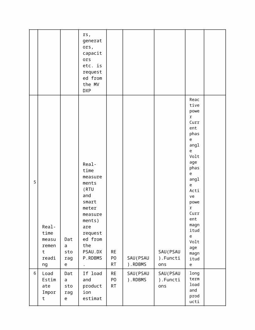
removed or
and proceed to step 6 in the normal sequence. Set the satus flag to "executed, but with limited accuracy.
index
ScenarioScenario Name: No. 4 - Gross error in load/production data
Step No.
Event.
Name of Process/ Activity
Description of Process/ Activity.
Service
Information Producer (Actor)
Information Receiver (Actor)
Information Exchanged
Requirements, R-ID
6.1
Gross error in MVSE load and production data
detect error
Gross error occurs as the load and production data are imported to PSAU.SE
REPORT
SAU(SSAU).Functions
SAU(SSAU).Functions
algorithm performance index
5.2
Erroneous data removed
detect error
Remove the erroneous data and proce
EXECUTE
SAU(SSAU).Functions
SAU(SSAU).Functions
algorithm performance index

ed to step 7 in the normal sequence. Set the satus flag to "executed, but with limited accuracy.
ScenarioScenario Name: No. 5 - Voltage measurement missing
Step No.
Event.Name of Process/ Activity
Description of Process/ Activity.
Service
Information Producer (Actor)
Information Receiver (Actor)
Information Exchanged
Requirements, R-ID
5.2
Voltage measurements (connection to LV) missing
Missing data
PSAU.SE doesn't receive voltage measurements and, thus, cannot be executed. Set the status flag to "error, execution not possible".
CANCEL
SAU(SSAU).Functions
SAU(SSAU).RDBMS
algorithm performance index

5.3
Quality index estimation update
algorithm performance index
PSAU.SE doesn't receive voltage measurements and, thus, cannot be executed. Set the status flag to "error, execution not possible".
CHANGE
SAU(SSAU).Functions
SAU(SSAU).RDBMS
algorithm performance index
ScenarioScenario Name: No. 6 - Real-time measurements missing
Step No.
Event.Name of Process/ Activity
Description of Process/ Activity.
Service
Information Producer (Actor)
Information Receiver (Actor)
Information Exchanged
Requirements, R-ID
5.3
Real-time measurements missing
Missing data
If real-time measurements (some or all) are missing, use load and production estimates (pseudo measurements)
EXECUTE
SAU(SSAU).Functions
SAU(SSAU).Functions
algorithm performance index

instead. Continue to step 6 in the normal sequence and set the status flag to "executed, but with limited accuray".
5.4
Quality indexestimation update
algorithm performance index
If real-time measurements (some or all) are missing, use load and production estimates (pseudo measurements) instead. Continue to step 6 in the normal sequence and set the status flag to "executed, but
CHANGE
SAU(SSAU).Functions
SAU(SSAU).RDBMS
algorithm performance index
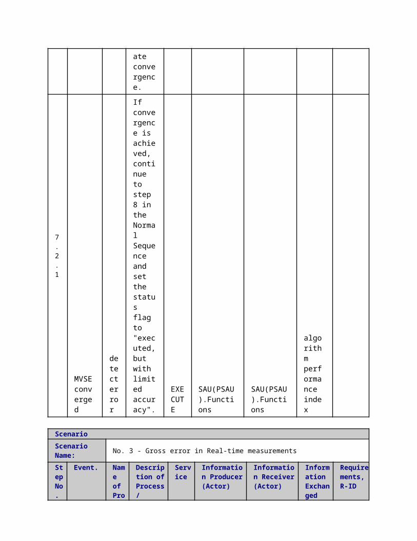
with limited accuray".
ScenarioScenario Name: No. 7 - Pseudo measurements missing
Step No.
Event.Name of Process/ Activity
Description of Process/ Activity.
Service
Information Producer (Actor)
Information Receiver (Actor)
Information Exchanged
Requirements, R-ID
5.4
Pseudo measurements missing
Missing data
If load and production estimates and some or all secondary substation measurements are missing, but real-time primary substation measurements exist, the PSAU.SE is "executed, but with very limited accuracy". This
EXECUTE
SAU(SSAU).Functions
SAU(SSAU).Functions
algorithm performance index
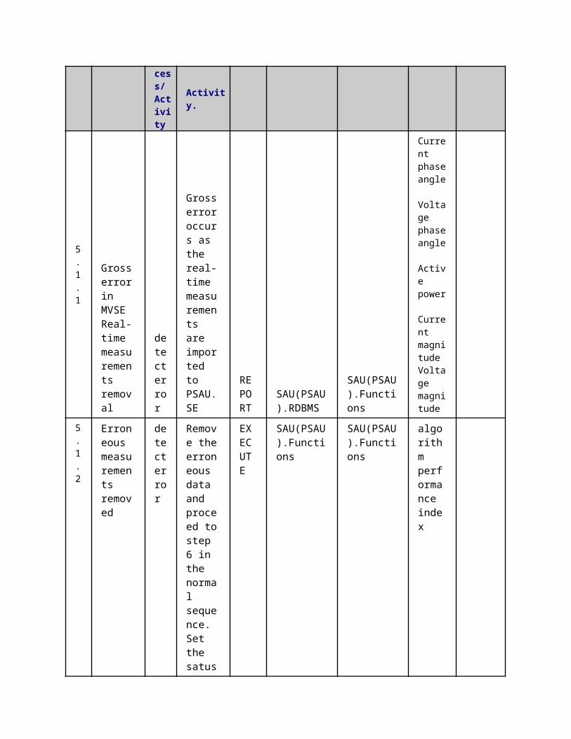
can be achieved by distributing the measured load to load and production points in relation to transformer and DG nominal powers.
5.5
Quality indexestimation update
algorithm performance index
If load and production estimates and some or all secondary substation measurements are missing, but real-time primary substation measurements exist, the
CHANGE
SAU(SSAU).Functions
SAU(SSAU).Functions
algorithm performance index
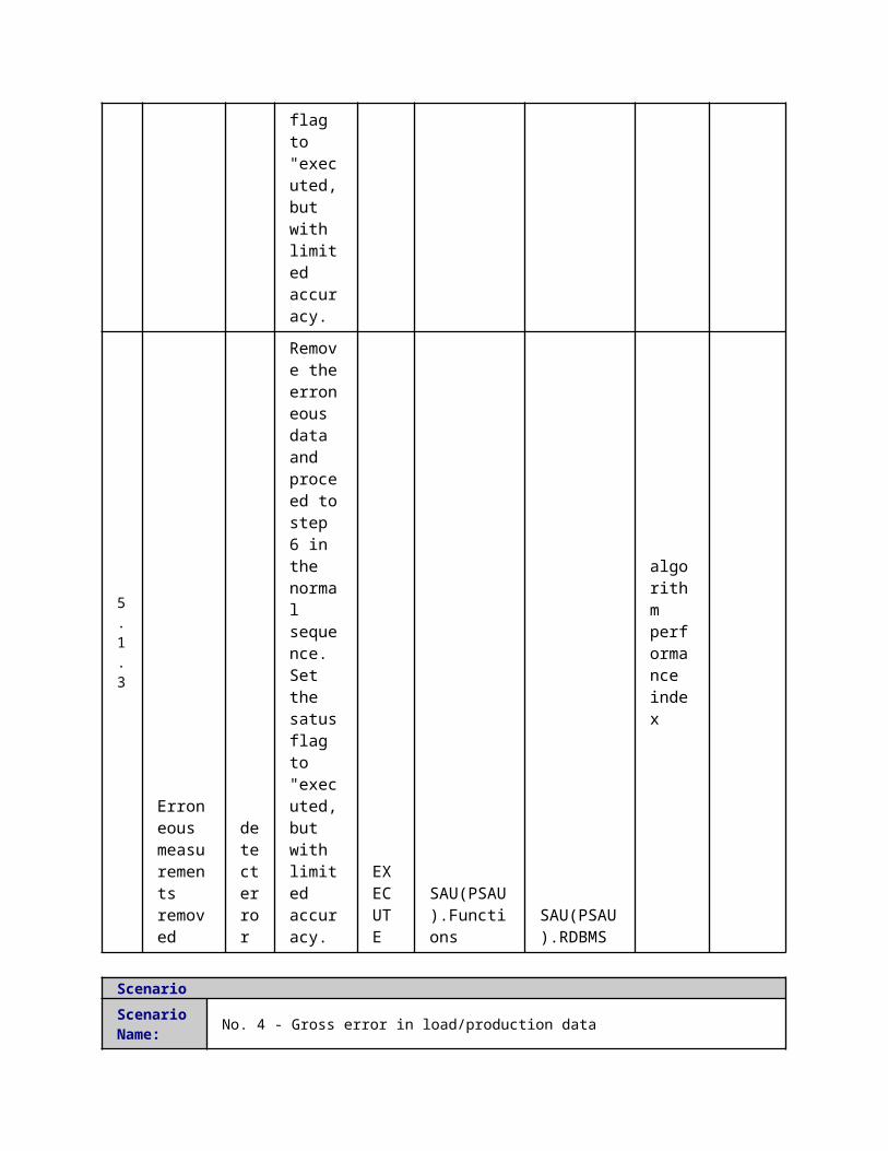
PSAU.SE is "executed, but with very limited accuracy". This can be achieved by distributing the measured load to load and production points in relation to transformer and DG nominal powers.
ScenarioScenario Name: No. 8 - Measurements not available
Step No.
Event.Name of Process/ Activity
Description of Process/ Activity.
Service
Information Producer (Actor)
Information Receiver (Actor)
Information Exchanged
Requirements, R-ID
5.5
No measurements available
Missing data
In all real-time and pseudo measurements are
CANCEL
SAU(SSAU).RDBMS
SAU(SSAU).Functions
algorithm performance index
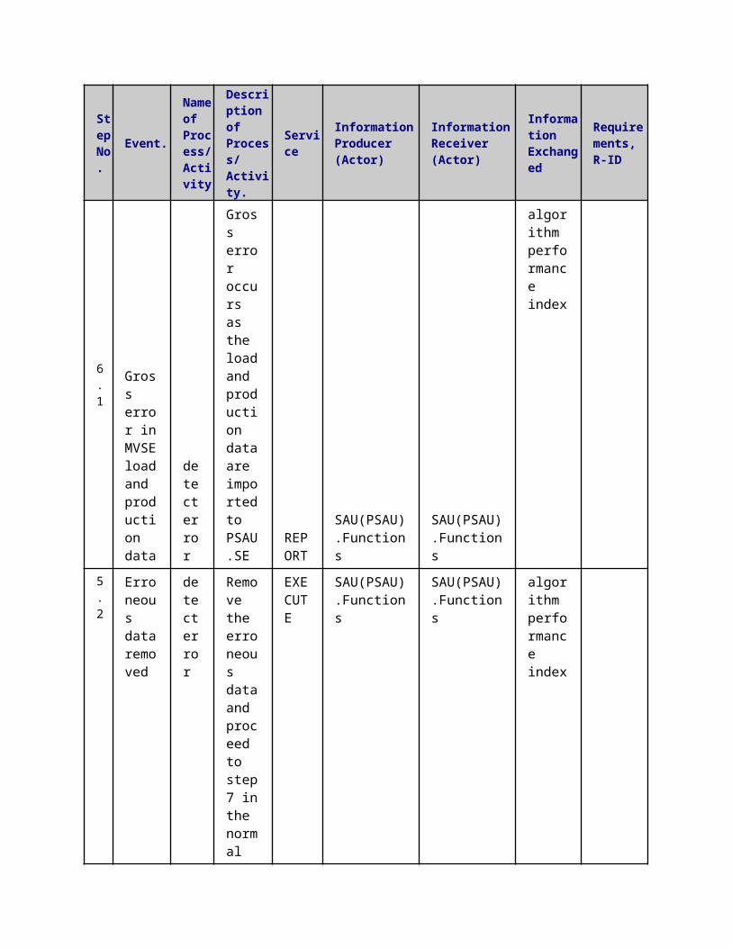
missing, PSAU.SE cannot be executed. Set the status flag to "error, execution not possible"
5.6
Quality indexestimation update
algorithm performance index
In all real-time and pseudo measurements are missing, PSAU.SE cannot be executed. Set the status flag to "error, execution not possible"
CHANGE
SAU(SSAU).Functions
SAU(SSAU).RDBMS
algorithm performance index
5 Information ExchangedInformation ExchangedName of Information (ID)
Description of Information Exchanged Requirements to information data
long term load Valid for the next 24 hours

and production forecast
short term load and production forecast
valid for the next 15-30 minutes
Current phase angle Current phase angle [rad]
Static Grid Data
Data exchanged:- Line parameters (R, X, B, G)- Line connections- Location of swithes, breakers and fuses- Transformer parameters
Switch and Fuse status
Der information
Nominal powerPower limitsType of DERConnection pointPhases connected (in case to which phase)
Voltage phase angle Voltage phase angle [rad]
Voltage magnitude Voltage magnitude [V]
Current magnitude Current magnitude [A]
Active power Active power injection [W]
Reactive power Reactive power injection [VAr]
Customer information
Nominal powerPower limitsType of customerConnection pointPhases connected (in case to which phase)
Quality indexQuality index of state estimation. Could be a number between 0 and 5 or a string
6 Requirements (optional)Requirements (optional)
7 Common Terms and DefinitionsCommon Terms and DefinitionsTerm Definition
8 Custom Information (optional)Custom Information (optional)Key Value Refers to Section
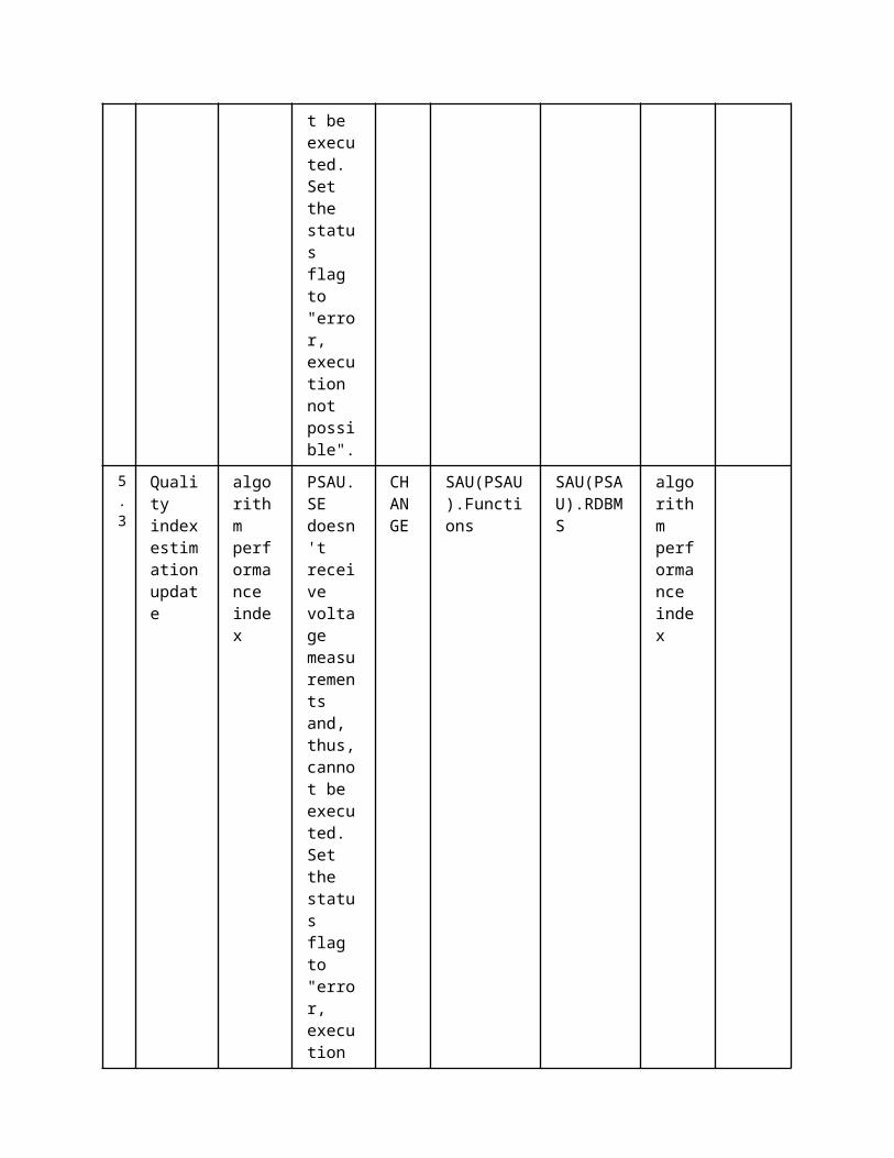
1 Description of the Use Case1.1 Name of the Use Case
Use Case Identification
IDArea / Domain(s)/Zone(s)
Name of the Use Case
249 Medium Voltage load/production Forecaster (MVF)
1.2 Version ManagementVersion Management
1.3 Scope and Objectives of Use CaseScope and Objectives of Use CaseScope
Objective(s)The objective of the PSAU forecaster is to forecast MV customer level load and micro-generation production 1-24 hours ahead and to provide a statistical measure for the forecast uncertainty.
Related businesscase(s)
1.4 Narrative of Use CaseNarrative of Use CaseShort descriptionThe medium voltage load forecasting algorithm provides estimated future load demands and micro-generation production for the medium voltage network. The input data are the historical measurements of smart meters, the flexible demand schedule and meteorological forecasts.Complete descriptionThe medium voltage load forecaster (PSAU.FC) will be developed in order to provide estimations of the load and micro generation production in the future. The secondary (MV and LV) and tertiary control algorithms will use this information. The PSAU.FC algorithm receives meteorological predictions up to the forecasting horizon, flexible demand scheduling and newly available measurements, recorded by the smart meters, which are stored in the PSAU.DXP.RDBMS. The PSAU.FC algorithm performs a regression of the input data on a model that has been trained with previous historical data. If the data from the PSAU.DXP.RDBMS holds missing values, the PSAU.FC algorithm will internally fill those with previous forecasts or load profiles for each specific type of client.
1.5 General RemarksGeneral Remarks
2 Diagrams of Use Case3 Technical Details3.1 Actors
ActorsGrouping Group Description
Actor Name Actor Type Actor DescriptionFurther information specific to this Use Case
PSAU.DXP.RDBMS
function Def. 2Platform for exchanging data between different actors and functions.
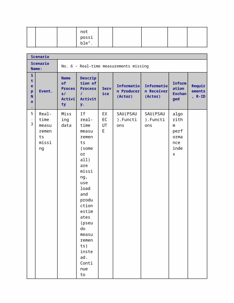
Actor in both Operation and Station zones
PSAU.FC function
3.2 Triggering Event, Preconditions, AssumptionsUse Case ConditionsActor/System/Information/Contract
Triggering Event
Pre-conditions Assumption
3.3 ReferencesReferences
No. References Type Reference Statu
sImpact on Use Case
Organistaor / Organisation
Link
3.4 Further Information to the Use Case for Classification / MappingClassification InformationRelation to Other Use CasesLevel of DepthDetailed use casePriorisationHighGeneric, Regional or National RelationGenericViewpointTechnicalFurther Keyword for ClassificationMedium Voltage Load Forecasting
4 Step by Step Analysis of Use Case4.1 Overview of Scenarios
Scenario ConditionsNo.
Scenario Name Primary Actor Triggering Event Pre-Condition Post-Condition
4.2 Steps - ScenariosScenarioScenario Name: No. 1 - Generate Short-Term and Long term MV Load Forecast
Step No.
Event.
Name of Process/ Activity
Description of Process/ Activity.
Service
Information Producer (Actor)
Information Receiver (Actor)
Information Exchanged
Requirements, R-ID
1 MVF algorithm collects historic load
Data storage
MVF algorithm receives the latest
REPORT
SAU(PSAU).RDBMS
SAU(PSAU).Functions
Load data
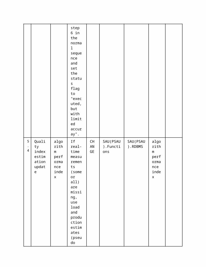
data.
smart meter data, if any.
2
MVF algorithm collects flexible demand schedule.
Data storage
MVF algorithm receives the flexible demand schedule, if any.
REPORT
SAU(PSAU).RDBMS
SAU(PSAU).Functions
Demand data
3
MVF algorithm collects meteorological forecasts.
Data storage
MVF algorithm receives the meteorological forecasts, if any.
REPORT
SAU(PSAU).RDBMS
SAU(PSAU).Functions
Meteorological Forcast
4
MVF algorithm executes
Load forecast
MVF algorithm generates forecasts for the requested horizon.
EXECUTE
SAU(PSAU).Functions
SAU(PSAU).Functions
short term load and production forecast
long term load and production forecast
5 MVF algoritm exports forecasting results
Data storage
MVF algorithm sends forecasted values to the DXP.
REPORT
SAU(PSAU).Functions
SAU(PSAU).RDBMS
short term load and production forecast
long term load and

production forecast
ScenarioScenario Name: No. 2- Error Management
Step No.
Event.Name of Process/ Activity
Description of Process/ Activity.
Service
Information Producer (Actor)
Information Receiver (Actor)
Information Exchanged
Requirements, R-ID
1.1
Communication with DXP cannot be established
Detect error
MVF algorithm sends forecasted values to the DXP
REPORT
SAU(PSAU).RDBMS
SAU(PSAU).Functions
Error flag
1.2
The MVF algorithm will fill, internally, those missing values in order to provide a Load forecast.
Data reconstruction
MVF algorithm sends forecasted values to the DXP
REPORT
SAU(PSAU).Functions
SAU(PSAU).Functions
Demand data Load data Meteorological Forcast
1.3
LVF algorithm sends forecasted values to the DXP
Missing data
MVF algorithm can't collect meteorological data. The third party is
REPORT
SAU(PSAU).RDBMS
SAU(PSAU).Functions
Error flag
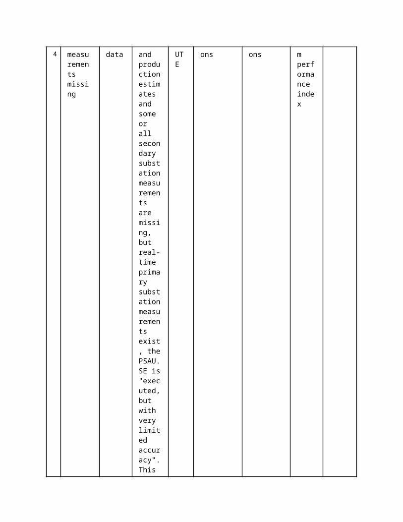
not able to produce a meteorological forecast or there has been a communication problem. The LF algorithm will produce a meteorological forecast and use it in order to provide a Load forecast.
1 Description of the Use Case1.1 Name of the Use Case
Use Case Identification
IDArea / Domain(s)/Zone(s)
Name of the Use Case
235 Low Voltage load/production Forecaster (LVF)
1.2 Version ManagementVersion ManagementBased on 0.1 2014-12-10 Daniel Olmeda, Hortensia AmarísUpdated: Fannar Thordarson (Dansk Energi), 2015-04-10
1.3 Scope and Objectives of Use CaseScope and Objectives of Use Case
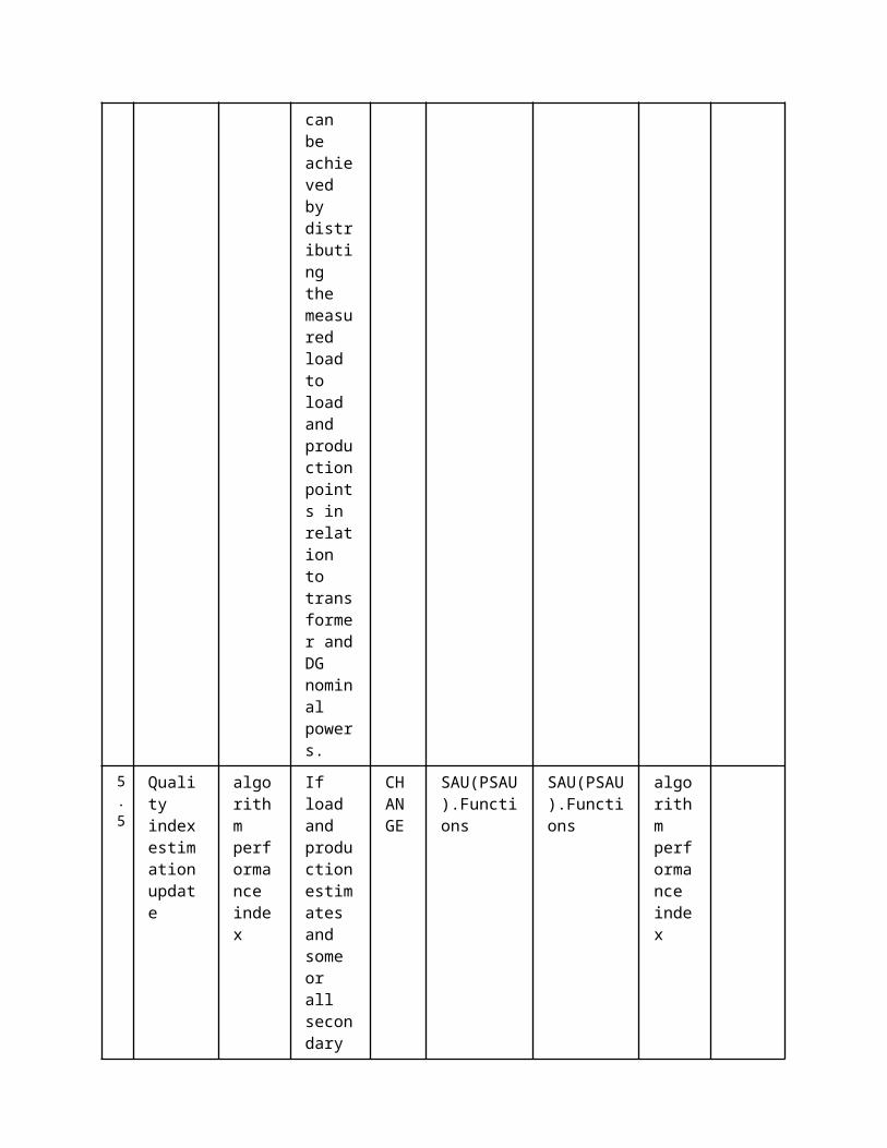
Scope
Objective(s)The objective of the SSAU forecast is to forecast LV customer level load and micro-generation production 1-24 hours ahead and to provide a statistical measure for the forecast uncertainty.
Related businesscase(s)
1.4 Narrative of Use CaseNarrative of Use CaseShort descriptionThe low voltage load forecasting algorithms outputs estimated future load demands and micro generation production for the low voltage network. The input data are the historical measurements of smart meters, the flexible demand schedule and meteorological forecasts.Complete descriptionThe low voltage load forecaster (SSAU.FC) will be developed in order to provide estimations of the load and micro-generation production in the future. The secondary (MV and LV) and tertiary control algorithms will use this information. The SSAU.FC algorithm receives meteorological predictions up to the forecasting horizon, flexible demand scheduling and newly available measurements, recorded by the smart meters, which are stored in the SAU(SSAU).RDBMS. The SSAU.FC algorithm performs a regression of the input data on a model that has been trained with previous historical data. If the received data from the SAU(SSAU).RDBMS holds missing values, the SSAU.FC algorithm will internally fill those with previous forecasts or load profiles for each specific type of client.
1.5 General RemarksGeneral Remarks
2 Diagrams of Use Case
3 Technical Details3.1 Actors
ActorsGrouping Group Description
Actor Name Actor Type Actor DescriptionFurther information specific to this Use Case

SAU(SSAU).Functions
function Forecaster function
SAU(SSAU).RDBMS function Database of secondary SAU
3.2 Triggering Event, Preconditions, AssumptionsUse Case ConditionsActor/System/Information/Contract
Triggering Event
Pre-conditions Assumption
3.3 ReferencesReferences
No. References Type Reference Statu
sImpact on Use Case
Organistaor / Organisation
Link
3.4 Further Information to the Use Case for Classification / MappingClassification InformationRelation to Other Use CasesLevel of DepthDetailed use casePriorisationHighGeneric, Regional or National RelationGenericViewpointTechnicalFurther Keyword for ClassificationLow Voltage Load forecasting
4 Step by Step Analysis of Use Case4.1 Overview of Scenarios
Scenario ConditionsNo.
Scenario Name Primary Actor Triggering Event Pre-Condition Post-Condition
4.2 Steps - ScenariosScenarioScenario Name: No. 1 - Generate Medium Term LV Load Forecast
Step No.
Event.
Name of Process/ Activity
Description of Process/ Activity.
Service
Information Producer (Actor)
Information Receiver (Actor)
Information Exchanged
Requirements, R-ID
1 DXP reports load data.
Data Storage
LVF algorithm requests the latest measur
REPORT
SAU(SSAU).RDBMS
SAU(SSAU).Functions
Load data

ements from the smart meter from the DXP.
5
LVF algorithm collects flexible demand schedule.
Data Storage
LVF algorithm receives the flexible demand schedule, if any.
REPORT
SAU(SSAU).RDBMS
SAU(SSAU).Functions
Demand data
7
LVF algorithm collects meteorological forecasts.
Data Storage
LVF algorithm receives the meteorological forecast, if any.
REPORT
SAU(SSAU).RDBMS
SAU(SSAU).Functions
Meteorological Forcast
8
LVF algorithm executes.
Load Forecast
LVF algorithm generates forecasts for the requested horizon.
EXECUTE
SAU(SSAU).Functions
SAU(SSAU).Functions
short term load and production forecast
9
LVF algorithm exports forecast results
Data Storage
LVF algorithm sends forecasted values to the DXP
REPORT
SAU(SSAU).Functions
SAU(SSAU).RDBMS
short term load and production forecast
ScenarioScenario Name: No. 2 - Generate Short Term LV Load Forecast
St Event. Name Descripti Servic Information Information Informati Require
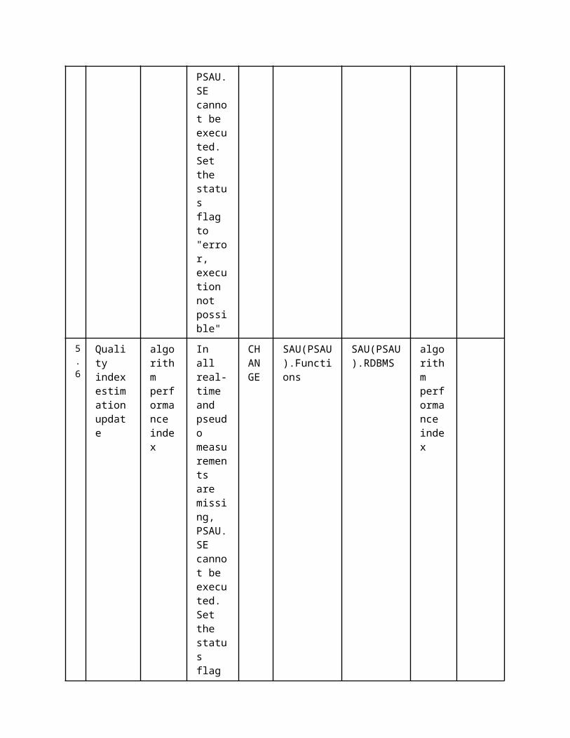
ep No.
of Process/ Activity
on of Process/ Activity.
e Producer (Actor)
Receiver (Actor)
on Exchanged
ments, R-ID
3
LVF algorithm collects historic load data.
Data Storage
LVF algorithm receives the latest smart meter data, if any.
REPORT
SAU(SSAU).RDBMS
SAU(SSAU).Functions
Load data
5
LVF algorithm collects flexible demand schedule.
Data Storage
LVF algorithm receives the flexible demand schedule, if any.
REPORT
SAU(SSAU).RDBMS
SAU(SSAU).Functions
Demand data
7
LVF algorithm collects meteorological forecasts.
Data Storage
LVF algorithm receives the meteorological forecasts, if any.
REPORT
SAU(SSAU).RDBMS
SAU(SSAU).Functions
Meteorological Forcast
8
LVF algorithm executes
Load Forecast
LVF algorithm generates forecasts for the requested horizon.
EXECUTE
SAU(SSAU).Functions
SAU(SSAU).Functions
long term load and production forecast
9 LVF algorithm exports forecasting
Data Storage
LVF algorithm sends forecasted
REPORT
SAU(SSAU).Functions
SAU(SSAU).RDBMS
long term load and production
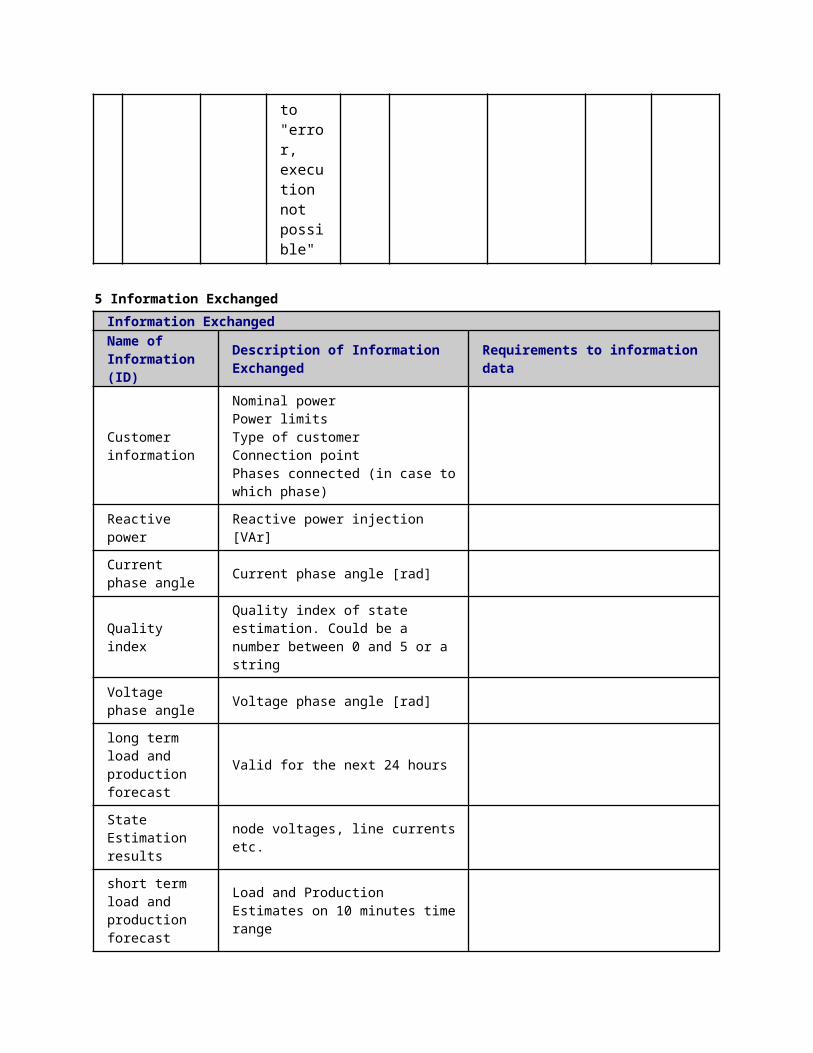
resultsvalues to the DXP
forecast
ScenarioScenario Name: No. 3 - Error Management
Step No.
Event.Name of Process/ Activity
Description of Process/ Activity.
Service
Information Producer (Actor)
Information Receiver (Actor)
Information Exchanged
Requirements, R-ID
1.1
No communication with data exchange platform
Detect error
Communication with DXP cannot be established
REPORT
SAU(SSAU).Functions
SAU(SSAU).Functions
Error flag
2Recontruction of data
Data reconstruction
The LVF algorithm will fill, internally, those missing values in order to provide a load forecast.
EXECUTE
SAU(SSAU).Functions
SAU(SSAU).Functions
Demand data Load data Meteorological Forcast
1.2
Cannot collect forecast data
Detect error
LVF algorithm can't collect meteorological data. The third party is not able to produce a meteorological forecast or there
EXECUTE
SAU(SSAU).Functions
SAU(SSAU).Functions
Error flag

has been a communication problem. The LF algorithm will produce a meteorological forecast and use it in order to provide a load forecast.
5 Information ExchangedInformation ExchangedName of Information (ID)
Description of Information Exchanged Requirements to information data
Demand data Series of [powert, time, ID of the bus]
Load data Series of [Power, time, ID of the bus]
Meteorological Forcast
for the area in which the load is located
Error flag Success or Failure
short term load and production forecast
valid for the next 15-30 minutes
long term load and production forecast
Valid for the next 24 hours
1 Description of the Use Case1.1 Name of the Use Case
Use Case Identification
IDArea / Domain(s)/Zone(s)
Name of the Use Case
137 Medium Voltage Network State Forecasting (MVSF)
1.2 Version ManagementVersion ManagementFrom V1.0 15.12.2014 Antti Mutanen
10.04.2015 - Edited by Fannar Thordarson: According to the updated version of the UC from Antti

Mutanen (uploaded to the wiki-page, on the 2/4 2015)
1.3 Scope and Objectives of Use CaseScope and Objectives of Use CaseScope
Objective(s)The objective of the PSAU.SF (formerly known as MVSF) is to obtain distributional forecasts for the MV network states. The available distributional load and production forecasts from the forecaster are used as inputs in calculation of state forecasts – K time steps ahead.
Related businesscase(s)
1.4 Narrative of Use CaseNarrative of Use CaseShort descriptionThe PSAU.SF provides forecasts for the states that are related to a specific MV network. The PSAU.SF will run once every 10 minutes after the PSAU.FC and deliver distributional properties for the pre-requested prediction horizon. The PSAU.SF algorithm utilizes the available secondary substation, MV customer, and distributed generation forecasts to provide distributional forecasts for the electric quantities of the MV network.Complete descriptionA PSAU.SF algorithm is developed that can be utilized on-demand for generating forecasts for the states in a medium voltage grid. A PSAU.SF calculation is done either in primary substation or in the control centre. The PSAU.SF is conditioned on the MV forecaster (PSAU.FC), since the needed predictions for secondary substation load, MV customer load, and distributed generation are acquired from the forecaster. These required input forecasts, corresponding to the K steps ahead, are retrieved from the Data eXchange Platform (PSAU.DXP.RDBMS). By accounting for the distributional properties of the predicted loads and productions, corresponding forecasts can be obtained for the medium voltage network states; node voltages, line current flows and node injections for all three phases. Hence, the PSAU.FC and the PSAU.SF are both required for generating forecasts for the medium voltage network, where the communication is through the PSAU.DXP.RDBMS. Estimated computing time will be several minutes.
The PSAU.SF procedure can be divided into three basic steps. First the state forecaster reads the scheduled MV network topology and configuration (for the upcoming K time steps ahead) from the PSAU.DXP.RDBMS. Then the forecasts for the network’s secondary substation, MV customer loads and distributed generators are retrieved from the PSAU.DXP.RDBMS. Since the PSAU.FC is based on filtered data the input data to the PSAU.SF doesn’t need filtering. Finally, the MV network state forecasts are generated by using data from these earlier steps. The output states are; node voltages, line current flows and node injections for all three phases. The results from the PSAU.SF are stored in the PSAU.DXP.RDBMS, available for other functions that request the specific state forecasts on the medium voltage network.
1.5 General RemarksGeneral Remarks
1. Basic Information to Use CaseSource(s) / Literature Link Conditions
(limitations) of UseDesign Specification: Medium Voltage
network State Estimator (MVSE) ß Medium Voltage network State
Forecaster (MVSF)
https://wiki.tut.fi/pub/IDE4L/DesignSpecification/
DesignSpecification_WP_5_1_MVSE_final.docxInternal (IDE4L)
2 Diagrams of Use Case
3 Technical Details3.1 Actors
ActorsGrouping Group Description
Actor Name Actor Type Actor DescriptionFurther information specific to this Use Case
SAU(PSAU).RDBMS function Def. 2
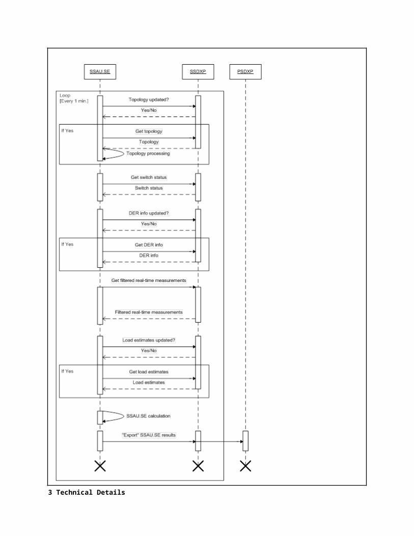
Platform for exchanging data between different actors and functions.
Actor in both Operation and Station zones
SAU(PSAU).Functions
function State forecast of PSAU
SAU(SSAU).MMS function MMS interface
SAU(PSAU).MMS function MMS interface
3.2 Triggering Event, Preconditions, AssumptionsUse Case ConditionsActor/System/Information/Contract
Triggering Event
Pre-conditions Assumption
3.3 ReferencesReferences
No. References Type Reference Statu
sImpact on Use Case
Organistaor / Organisation
Link
3.4 Further Information to the Use Case for Classification / MappingClassification InformationRelation to Other Use CasesLevel of DepthDetailed Use CasePriorisationHighGeneric, Regional or National RelationGenericViewpointTechnicalFurther Keyword for ClassificationState Forecasting, Distribution Network
4 Step by Step Analysis of Use Case4.1 Overview of Scenarios
Scenario ConditionsNo.
Scenario Name Primary Actor Triggering Event Pre-Condition Post-Condition
4.2 Steps - ScenariosScenarioScenario Name: No. 1 - Medium voltage state forecast
Step No.
Event.
Name of Process/ Activity
Description of Process/ Activity.
Service
Information Producer (Actor)
Information Receiver (Actor)
Information Exchanged
Requirements, R-ID

1
Grid data (topology and parameters) import
Data storage
If grid data information has not been imported before or if topology information has changed the network topology import function requests network topology information from the SSAU.DXP.RDBMS.
REPORT
SAU(PSAU).RDBMS
SAU(PSAU).Functions
Static Grid Data
3
DER and switch schedule import
Data storage
If grid data information has not been imported before or if topology information has changed the network topology import function requests network topology information from the SSAU.DXP.RDBMS.
REPORT
SAU(PSAU).RDBMS
SAU(PSAU).Functions
DER and switch schedules
4 Get Data If grid RE SAU(PSAU). SAU(PSAU). short term
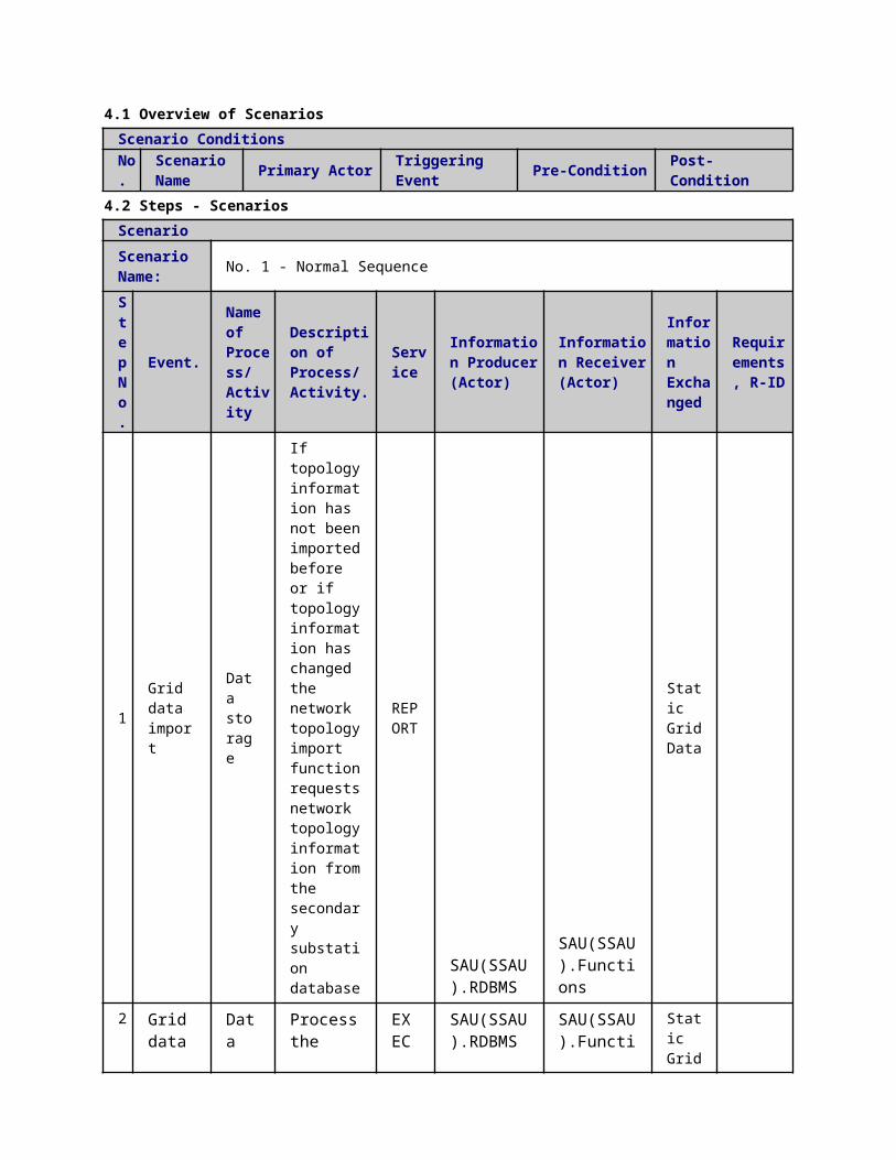
Load forecasts. Load and production forecasts are requested from the secondary substation database.
storage
data information has not been imported before or if topology information has changed the network topology import function requests network topology information from the SSAU.DXP.RDBMS.
PORT RDBMS Functions
load and production forecast long term load and production forecast
5
LV network connection point voltage forecast is requested from SSAU
Data acquisition
If grid data information has not been imported before or if topology information has changed the network topology import function requests network topology information from the SSAU.DXP.RDBMS.
REPORT
SAU(SSAU).MMS
SAU(PSAU).MMS
MV connection point Voltage forecast .
6 LV netwo
Data stora
If grid data
REPO
SAU(PSAU).MMS
SAU(SSAU).MMS
MV conn
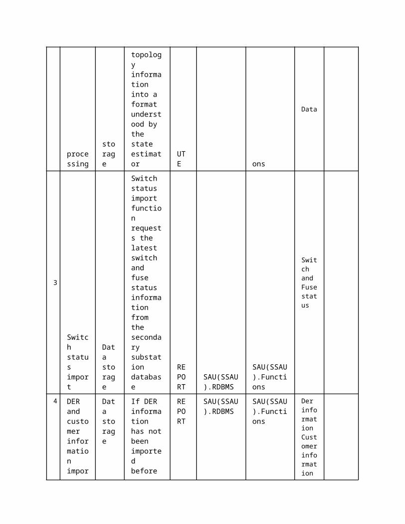
rk connection point voltage forecast is requested from MV DXP. ge
information has not been imported before or if topology information has changed the network topology import function requests network topology information from the SSAU.DXP.RDBMS. RT
ection point Voltage forecast
7
LVSF calculation
State forecast
If grid data information has not been imported before or if topology information has changed the network topology import function requests network topology information from the SSAU.DXP.RDBMS.
REPORT
SAU(PSAU).Functions
SAU(PSAU).Functions
State forcasting result
8 The MVSF result
Data storage
If grid data informatio
REPORT
SAU(PSAU).Functions
SAU(PSAU).RDBMS
State forcasting

s are exported to SSAU
n has not been imported before or if topology information has changed the network topology import function requests network topology information from the SSAU. RDBMS. result
9
The MVSF results are exported to MV DXP.
Data Report
Note, only aggregated results are exported to the MV DXP.
REPORT
SAU(PSAU).RDBMS
SAU(SSAU).MMS
State forcasting result
10
The MVSF results are exported to MV DXP.
Data Report
Note, only aggregated results are exported to the MV DXP.
REPORT
SAU(PSAU).MMS
SAU(SSAU).MMS
State forcasting result
5 Information ExchangedInformation ExchangedName of Information (ID)
Description of Information Exchanged Requirements to information data
DER and switch schedules
Voltage forecast
State forecasting result
line currents, node voltages, line power flow, estimated load and productions etc.
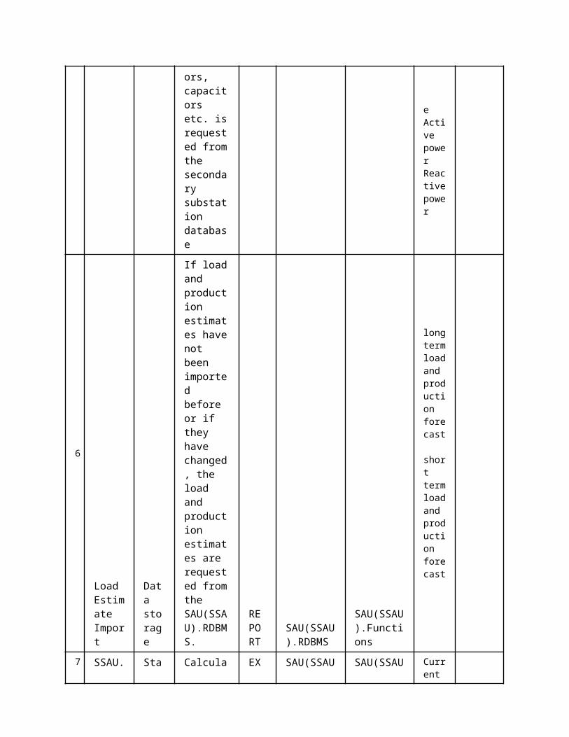
Static Grid Data
Included:- Line parameters (R, X, B, G)- Line connections- Location of swithes, breakers and fuses- Transformer parameters
short term load and production forecast
valid for the next 15-30 minutes
long term load and production forecast
Valid for the next 24 hours
1 Description of the Use Case1.1 Name of the Use Case
Use Case Identification
IDArea / Domain(s)/Zone(s)
Name of the Use Case
136 Low Voltage Network State Forecasting (LVSF)
1.2 Version ManagementVersion ManagementFrom V1.0 15.12.2014 Antti Mutanen
Added scenario step 9.
10.04.2015 - Edited by Fannar Thordarson: according to the updated UC from Antti Mutanen (uploaded to the wiki-page, on the 2/4 2015).
1.3 Scope and Objectives of Use CaseScope and Objectives of Use CaseScope
Objective(s)The objective of the SSAU.SF (formerly known as LVSF) is to obtain distributional forecasts for the LV network states. The available distributional load and production forecasts from the forecaster are used as inputs in calculation of state forecasts – K time steps ahead.
Related businesscase(s)
1.4 Narrative of Use CaseNarrative of Use CaseShort descriptionSSAU.SF provides forecasts for the states that are related to the specific secondary substation on a low voltage network. The SSAU.SF will run onec every 10 minutes after the SSAU.FC and deliver distributional properties for the pre-requested prediction horizon. The SSAU.SF algorithm utilizes the available customer load forecasts and micro-production forecasts to provide distributional forecasts for the electric quantities of the LV states.Complete descriptionA SSAU.SF algorithm is developed that can be utilized on-demand for generating forecasts for the

states in a low voltage grid. SSAU.SF calculation is done in a decentralized manner where the SSAU.SF algorithm is run in an intelligent device located in the secondary substation. The SSAU.SF is conditioned on the LV forecasts (SSAU.FC), since the delivered predictions for customer load and micro-production, acquired from the forecaster, are required for providing the LV state forecasts. These required input forecasts, corresponding to the K steps ahead, are retrieved from the Data eXchange Platform (SAU(SSAU).RDBMS). By accounting for the distributional properties of the predicted customer load and the micro-production forecasts, corresponding forecasts can be obtained for the low voltage network states; node voltages, line current flows and line power flows for all three phases. Hence, the SSAU.FC and the SSAU.SF are both required for generating forecasts for the low voltage network, where the communication is through the SAU(SSAU).RDBMS. Estimated computing time will be several minutes.
The SSAU.SF procedure can be divided into three basic steps. First are the state forecaster reads the scheduled LV network topology and configuration (for the upcoming K time steps ahead) from the SAU(SSAU).RDBMS. Then the forecasts for the network’s customer loads and micro-productions are retrieved from the SSAU.DXPRDBMS. Since the SSAU.FC is based on filtered data the input data to the SSAU.SF doesn’t need filtering. Finally, the LV network state forecasts are generated by using data from earlier steps. The output states are; node voltages, line current flows and node injections for all three phases. The results from the SSAU.SF are stored in the SAU(SSAU).RDBMS, available for other functions that request the specific state forecasts on the low voltage network.
1.5 General RemarksGeneral Remarks
2 Diagrams of Use Case
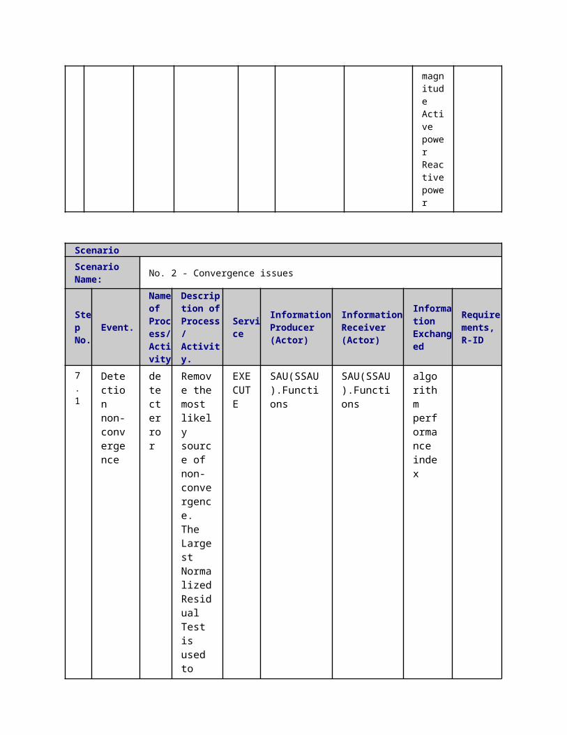
3 Technical Details3.1 Actors
ActorsGrouping Group Description
Actor Name Actor Type Actor DescriptionFurther information specific to this Use Case
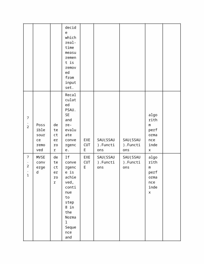
SAU(SSAU).Functions
functionState forecast function
SAU(SSAU).RDBMS
function Def. 2Platform for exchanging data between different actors and functions.
Actor in both Operation and Station zones
SAU(PSAU).RDBMS
function
Def. 2Platform for exchanging data between different actors and functions.
Actor in both Operation and Station zones
SAU(PSAU).MMS function MMS Interface
SAU(SSAU).MMS function MMS Interface
3.2 Triggering Event, Preconditions, AssumptionsUse Case ConditionsActor/System/Information/Contract
Triggering Event
Pre-conditions Assumption
3.3 ReferencesReferences
No. References Type Reference Statu
sImpact on Use Case
Organistaor / Organisation
Link
3.4 Further Information to the Use Case for Classification / MappingClassification InformationRelation to Other Use CasesLevel of DepthDetailed Use CasePriorisationHighGeneric, Regional or National RelationGenericViewpointTechnicalFurther Keyword for ClassificationState Forecasting, Distribution Network
4 Step by Step Analysis of Use Case4.1 Overview of Scenarios
Scenario ConditionsNo.
Scenario Name Primary Actor Triggering Event Pre-Condition Post-Condition
4.2 Steps - ScenariosScenario

Scenario Name: No. 1 – SSAU state forecast Started
Step No.
Event.
Name of Process/ Activity
Description of Process/ Activity.
Service
Information Producer (Actor)
Information Receiver (Actor)
Information Exchanged
Requirements, R-ID
1
Grid data (topology and parameters) import
Data storage
If grid data information has not been imported before or if topology information has changed the network topology import function requests network topology information from the SSAU.DXP.RDBMS.
REPORT
SAU(SSAU).RDBMS
SAU(SSAU).Functions
Static Grid Data
4 DER and switch schedule import
Data storage
If grid data information has not been imported before or if topology information has changed the network topology import function requests
REPORT
SAU(SSAU).RDBMS
SAU(SSAU).Functions
DER and switch schedules

network topology information from the SSAU.DXP.RDBMS.
5
Get Load forecasts. Load and production forecasts are requested from the secondary substation database.
Data storage
If grid data information has not been imported before or if topology information has changed the network topology import function requests network topology information from the SSAU.DXP.RDBMS.
REPORT
SAU(SSAU).RDBMS
SAU(SSAU).Functions
short term load and production forecast long term load and production forecast
6 MV network connection point voltage forecast is requested from PSAU
Data acquisition
If grid data information has not been imported before or if topology information has changed the network topology import function requests network
REPORT
SAU(PSAU).MMS
SAU(SSAU).MMS
MV connection point Voltage forecast

topology information from the SSAU.DXP.RDBMS.
7
MV network connection point voltage forecast is requested from MV DXP.
Data acquisition
If grid data information has not been imported before or if topology information has changed the network topology import function requests network topology information from the SSAU.DXP.RDBMS.
REPORT
SAU(PSAU).MMS
SAU(SSAU).MMS
8 LVSF calculation
State forecast
If grid data information has not been imported before or if topology information has changed the network topology import function requests network topology
REPORT
SAU(SSAU).Functions
SAU(SSAU).Functions
State forcasting result
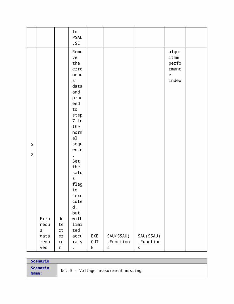
information from the SSAU.DXP.RDBMS.
9
The LVSF results are exported to MV DXP.
Data storage
Note, only aggregated results are exported to the MV DXP.
REPORT
SAU(SSAU).Functions
SAU(SSAU).RDBMS
State forcasting result
10
The LVSF results are exported to MV DXP.
Data Report
Note, only aggregated results are exported to the MV DXP.
REPORT
SAU(SSAU).MMS
SAU(PSAU).MMS
State forcasting result
5 Information ExchangedInformation ExchangedName of Information (ID)
Description of Information Exchanged Requirements to information data
State forcasting result
node voltages, line currents, aggregated production etc.
MV connection point Voltage forecast
DER and switch schedules
Static Grid Data
Included:- Line parameters (R, X, B, G)- Line connections- Location of swithes, breakers and fuses- Transformer parameters
short term load and production forecast
valid for the next 15-30 minutes
long term load and production forecast
Valid for the next 24 hours
1 Description of the Use Case1.1 Name of the Use Case
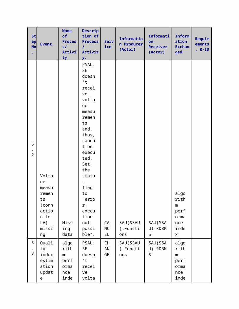
Use Case Identification
IDArea / Domain(s)/Zone(s)
Name of the Use Case
139 Network Description Update (NDU)
1.2 Version ManagementVersion Management
1.3 Scope and Objectives of Use CaseScope and Objectives of Use Case
ScopeThe use case consists in updating the network description (topology, assets, customers) of the RDBMS – located in substations – when a change is performed in the Distribution Management System (DMS) – located in the Control Center.
Objective(s)This information is needed to perform correctly algorithms (State Estimation, State Forecasting, Optimal Power Flow, …) and control actions in order to increase the network reliability and performance.
Related businesscase(s)
1.4 Narrative of Use CaseNarrative of Use CaseShort descriptionThis update process maintains aligned:
the description of the network topology the list of assets and their parameters the list of customers and some relevant information
among the main database of the DMS – located in the utility Control Center – and the distributed database of RDBMS in the Primary and Secondary Substations every time a network change is performed in the DMS or a customer change is performed in the CIS.Complete descriptionThe DMS needs a subset of the whole information, in order to locally execute algorithms such as the State Estimation or the Optimal Power Flow.The same data are needed in primary and secondary substation – within the RDBMS – to allow a local execution of those algorithms. This distribution and replication of the information among different subsystems requires update processes every time a change is performed, and it has to be completed roughly in less than one minute in order to keep updated every node.One of the following changings have to trigger an update of the network description:
a new part of the grid is added/changed a new customer/generation is added/changed[1] on the grid
The first one is activated by DMS which manages, interacting with Asset Manager in the Enterprise level, extensions or modifications of the grid. Instead the second trigger is activated by Customer Information System which notifies possible customer/generation to the DMS. So that this first step identifies two different functions:
Customer change: a customer/generation contract change is performed through CIS in the Enterprise level than a notification is sent to the DMS through an Enterprise Service Bus (this notification architecture is not in the project scope)
Grid change: DMS, using information from AMS, manages and performs extensions and modifications of the grid.
In both cases, customer or grid change, if the change is referred to a section of the LV grid or a customer/production connected on it, the update involves the secondary substation feeding
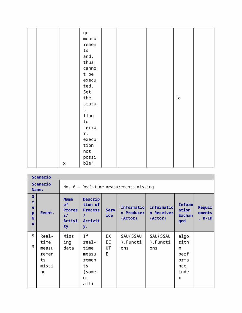
the section/customer/production.If the change is referred to a section of the MV grid or a customer/production connected on it, the update involves:
the primary substation feeding the section/customer/production in the standard grid configuration
the other primary substations that could feed the element when a non-standard configuration is applied (e.g. after a fault occurs)
When one of the two trigger conditions is notified to the DMS the Network Description Update function is performed. DMS sends a description packet related to the updated grid part to the substation automation unit, which parses the information and updates its internal grid description.
In order to limit efforts in integration and to provide an easily-exploitable solution, the use case must leverage on standard protocols such as the Common Information Model (CIM) .
[1] customer/production change means for instance: the change of the contractual power; enable/disable the customer’s contract; …
1.5 General RemarksGeneral Remarks
2 Diagrams of Use Case
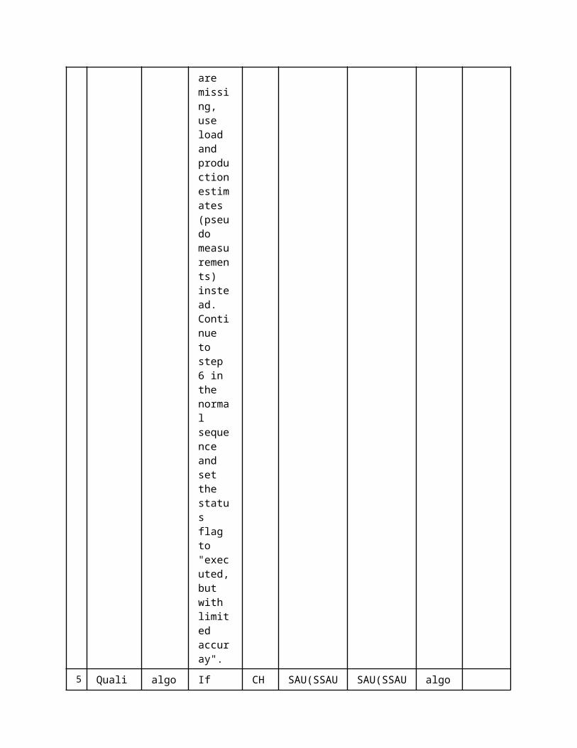
3 Technical Details3.1 Actors
ActorsGrouping Group Description
Actor Name Actor Type Actor DescriptionFurther information specific to this Use Case
DMS.MMS function MMS interface
SAU(SSAU).RDBMS
function
Secondary Substation Automation Unit Relational Database Management System It represents the database and the related management system which compose the Secondary Substation Automation Unit storage system
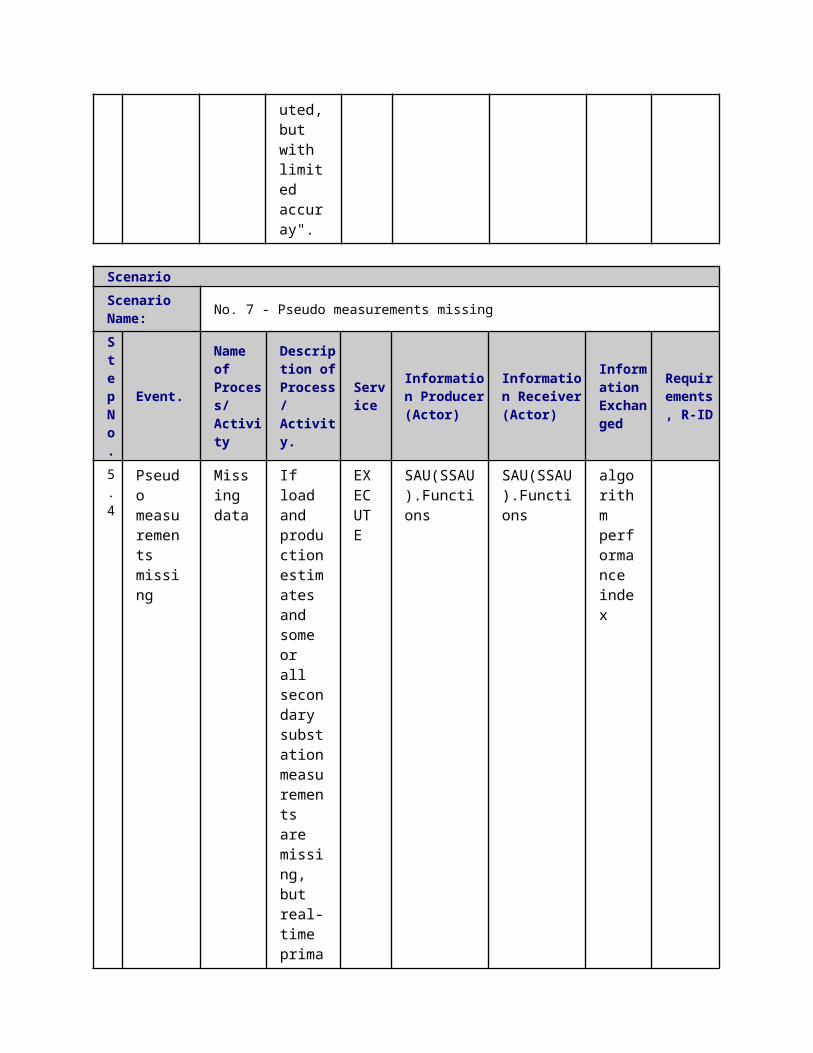
SAU(PSAU).RDBMS
function
Primary Substation Automation Unit Relational Database Management System It represents the database and the related management system which compose the Primary Substation Automation Unit storage system
SAU(SSAU).Functions
function
It represents the topology manager functionality implemented in the Secondary Substation Automation Unit
SAU(PSAU).Functions
functionIt represents the topology manager functionality implemented in the Primary Substation Automation Unit
SAU(SSAU).MMS MMS Interface
SAU(PSAU).MMS MMS Interface
3.2 Triggering Event, Preconditions, AssumptionsUse Case ConditionsActor/System/Information/Contract
Triggering Event
Pre-conditions Assumption
3.3 ReferencesReferences
No. References Type Reference Statu
sImpact on Use Case
Organistaor / Organisation
Link
3.4 Further Information to the Use Case for Classification / MappingClassification InformationRelation to Other Use CasesLevel of DepthPrimary Use CasePriorisation??Generic, Regional or National RelationEuropeanViewpointTechnicalFurther Keyword for ClassificationNetwork Model
4 Step by Step Analysis of Use Case4.1 Overview of Scenarios
Scenario ConditionsNo.
Scenario Name Primary Actor Triggering Event Pre-Condition Post-Condition
4.2 Steps - ScenariosScenarioScenario Name: No. 1 - MV Network Update

Step No.
Event.
Name of Process/ Activity
Description of Process/ Activity.
ServiceInformation Producer (Actor)
Information Receiver (Actor)
Information Exchanged
Requirements, R-ID
1
Change (topology and parameters) in MV Network
Grid change
DMS sends the new MV network CIM model to the PSAU.TM
REPORT
DMS.MMSSAU(SSAU).MMS
CIM Network Model
2
CIM model received
CIM Parsing
PSAU.TM parses the received CIM model
EXECUTE
SAU(PSAU).RDBMS
SAU(PSAU).Functions
CIM Network Model
3
CIM model parsed
Data Storage
PSAU.TM stores the new network model in the PSAU.RDBMS
REPORT
SAU(PSAU).Functions
SAU(PSAU).RDBMS
CIM Network Model
ScenarioScenario Name: No. 2 - LV Network Update
Step No.
Event.
Name of Process/ Activity
Description of Process/ Activity.
ServiceInformation Producer (Actor)
Information Receiver (Actor)
Information Exchanged
Requirements, R-ID
1
Change (both topology and parameters) in LV Network
Grid change
DMS sends the new LV network CIM model to the SSAU.TM
REPORT
DMS.MMSSAU(PSAU).MMS
CIM Network Model
2 CIM model
CIM
SSAU.TM
EXECUT
SAU(SSAU).RDBMS
SAU(SSAU).Functions
CIM Netw
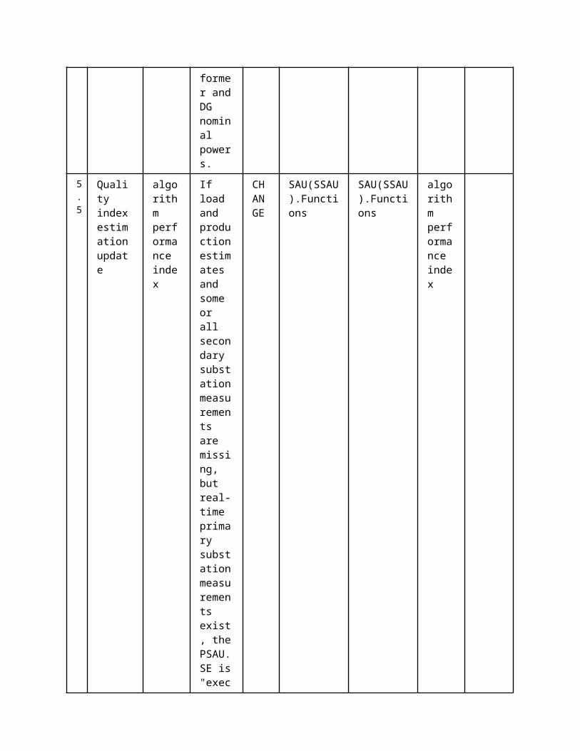
received
Parsing
parses the received CIM model
Eork Model
3
CIM model parsed
Data Storage
SSAU.TM stores the new network model in the SSAU.RDBMS
REPORT
SAU(SSAU).Functions
SAU(SSAU).RDBMS
CIM Network Model
ScenarioScenario Name: No. 3 - Customer/DER update
Step No.
Event.Name of Process/ Activity
Description of Process/ Activity.
Service
Information Producer (Actor)
Information Receiver (Actor)
Information Exchanged
Requirements, R-ID
1Customer/DER change
Customer/DER change
Customer/DER change
REPORT
DMS.MMS
SAU(SSAU).MMSSAU(PSAU).MMS
CIM Network Model
2
Parsing of CIM table (primary substation)
CIM parsing
Parsing of CIM table (primary substation)
EXECUTE
SAU(PSAU).RDBMSSAU(SSAU).RDBMS
SAU(PSAU).FunctionsSAU(SSAU).Functions
CIM Network Model
3
New customer/DER info storage (primary substation)
Data Storage
New customer/DER info storage (primary substation)
REPORT
SAU(PSAU).Functions
SAU(PSAU).RDBMS
CIM Network Model
4
New customer/Der info storage (Secondary substation)
Data Storage
New customer/Der info storage (Secondary substation)
REPORT
SAU(SSAU).Functions
SAU(SSAU).RDBMS
CIM Network Model
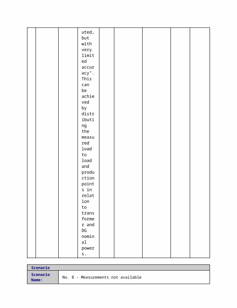
5 Information ExchangedInformation ExchangedName of Information (ID)
Description of Information Exchanged Requirements to information data
CIM Network Model
LV and/or MV Network (or piece of network) modelled with CIM XML
1 Description of the Use Case1.1 Name of the Use Case
Use Case Identification
IDArea / Domain(s)/Zone(s)
Name of the Use Case
140 Protection Configuration Update (PCU)
1.2 Version ManagementVersion Management
1.3 Scope and Objectives of Use CaseScope and Objectives of Use Case
ScopeThe use case consists in updating the configuration file of protection devices when a change is done in the network configuration (status of breakers and disconnectors).
Objective(s)This information is needed to perform correctly the FLISR algorithms on MV – for each network configuration – in order to further increase the network reliability and the service continuity (i.e. SAIDI, SAIFI, …).
Related businesscase(s)
1.4 Narrative of Use CaseNarrative of Use CaseShort descriptionThe use case consists in updating the configuration file of protection devices when a change is done in the network configuration (status of breakers and disconnectors).The changes has to be reflected in the setting of protection functions and in the coordination between protection devices used by the FLISR use case.Complete descriptionThe update process takes place only when a change is performed in the network configuration (status of breakers and disconnectors) and it has to be completed roughly in less than one minute.This update includes:
changing in settings such as maximum current threshold, voltage/frequency bands, trip delays
changing in the logic selectivity rules (publish/subscribe relations)
Protection devices configurations are updated by the Primary Substation Unit (PSAU) after it detects a change in the downstream network configuration (MV network real time monitoring Use Case). The PSAU reads the actual status of the network in the local data storage system. The involved functions are:
Data reading: PSAU reads the current network configuration from the local database

that it has been written by MV real time monitoring. Protection update: when PSAU detects a network configuration update it starts the
update process sending the new parameters values to the protection devices. Devices that receive the update request parse it and write their new parameters values according with the PSAU notification.
In order to limit efforts in integration and to provide an easily-exploitable solution the use case must leverage on standard protocols such as the IEC61850 Substation Configuration Language (SCL) for the description of the automation system and the IEC61850-MMS for the updates of the configuration files/values.
1.5 General RemarksGeneral Remarks
2 Diagrams of Use Case
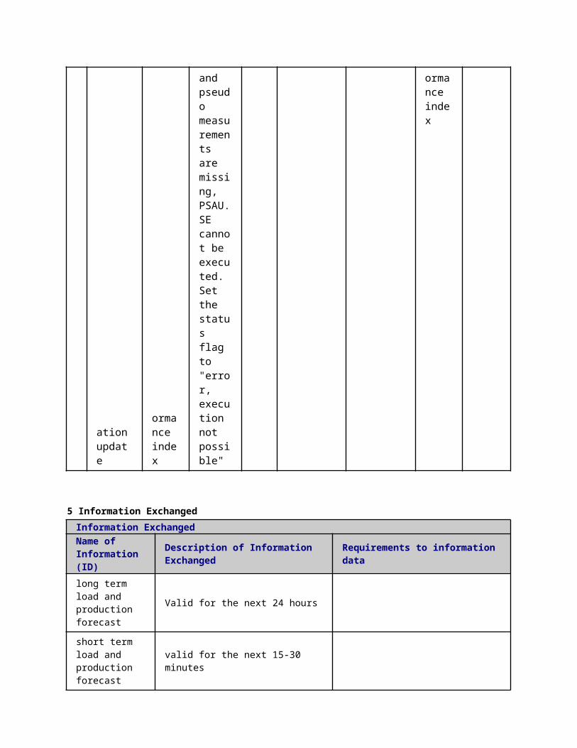
3 Technical Details3.1 Actors
ActorsGrouping Group Description
Actor Name Actor Type Actor DescriptionFurther information specific to this Use Case
SAU(PSAU).RDBMS
function
Primary Substation Automation Unit Relational Database Management System It represents the database and the related management system which compose the Primary Substation Automation Unit storage system
IED(PSIED).MMS
function
Intelligent Electronic Device (IED), protection devicesDef. 2Any other Intelligent Electronic Device (IED) not included in the list. IEDs are devices incorporating one or more processors with the capability to receive or send data/control from or to an external source (e.g., electronic multifunction meters, digital relays, controllers).
Similar devices: Power Quality Meter (PQM), and Remote Terminal Unit (RTU).
Actor in Field zone
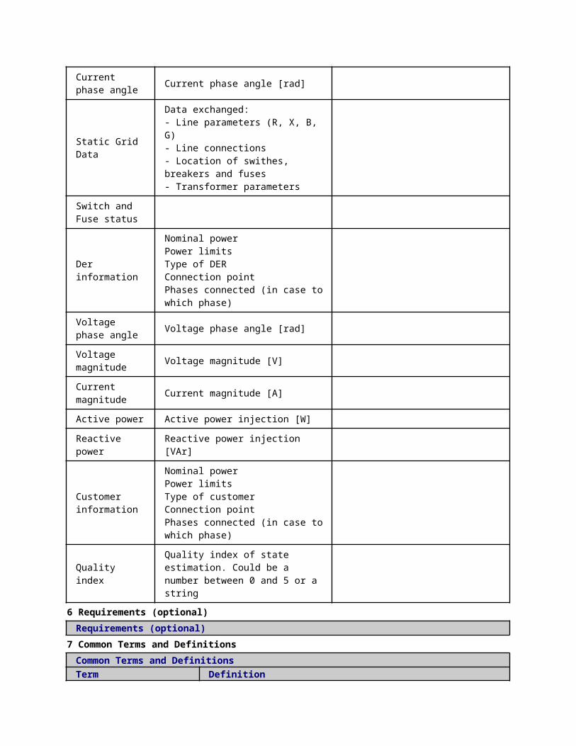
SAU(PSAU).Functions
function
Primary Substation Automation Unit Protection System Configurator (PSAU.PSC)It represents the protection system configuration functionalities which are implemented in the Primary Substation Automation Unit
SAU(PSAU).MMS function MMS Interface
3.2 Triggering Event, Preconditions, AssumptionsUse Case ConditionsActor/System/Information/Contract
Triggering Event
Pre-conditions Assumption
3.3 ReferencesReferences
No. References Type Reference Statu
sImpact on Use Case
Organistaor / Organisation
Link
3.4 Further Information to the Use Case for Classification / MappingClassification InformationRelation to Other Use CasesDecentralized FLISR;Level of DepthPrimary Use CasePriorisation??Generic, Regional or National RelationEuropeanViewpointTechnicalFurther Keyword for ClassificationProtection System, FLISR
4 Step by Step Analysis of Use Case4.1 Overview of Scenarios
Scenario ConditionsNo.
Scenario Name Primary Actor Triggering Event Pre-Condition Post-Condition
4.2 Steps - ScenariosScenarioScenario Name: No. 1 - Protection Device Update [normal]
Step No.
Event.
Name of Process/ Activity
Description of Process/ Activity.
Service
Information Producer (Actor)
Information Receiver (Actor)
Information Exchanged
Requirements, R-ID
1 Periodically
Data stora
PSAU.PSC
GET SAU(PSAU).RDBMS
SAU(PSAU).Functions
MV Networ
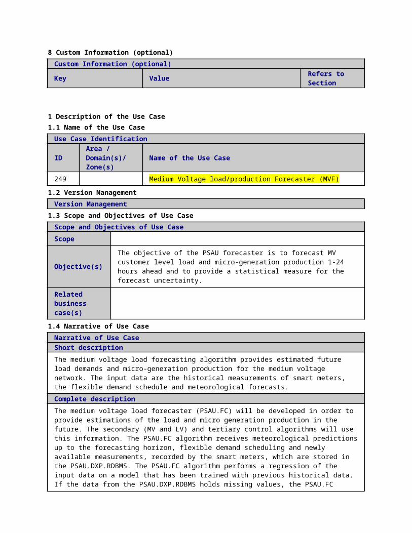
ge
reads network configuration from PSAU.RDBMS
k configuration
2
Network configuration updated
Protection update
PSAU.PSC retrieved a new network configuration from PSAU.RDBMS, PSAU.PSC builds a new PD configuration and it sends, using IEC61850 MMS and SCL file transfer, new configuration to the involved IEDs
EXECUTE
SAU(PSAU).MMS
IED(PSIED).MMS
Protection Device Configuration
5 Information ExchangedInformation ExchangedName of Information (ID)
Description of Information Exchanged Requirements to information data
MV Network configuration
Dynamic network configuration for MV grid (breakers/disconnectors status)
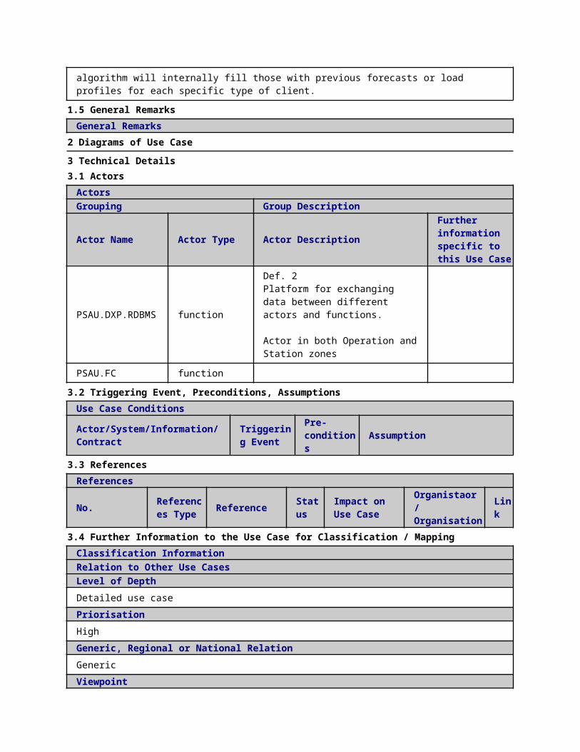
Protection Device Configuration
Configuration and settings of a protection device (current/voltage threshold, time, etc.)
1 Description of the Use Case1.1 Name of the Use Case
Use Case Identification
IDArea / Domain(s)/Zone(s)
Name of the Use Case
255 Control Centre Power Control (CCPC): Offline Operation
1.2 Version ManagementVersion Management
1.3 Scope and Objectives of Use CaseScope and Objectives of Use Case
ScopeThe CCPC is part of a more general scheme called “Congestion Managementâ€. Offline operation of the CCPC tries to solve MV network �congestions for the Day-Ahead right after the market clearing.
Objective(s)The objective of the CCPC is to solve MV congestions for Day-ahead (or hours-ahead) by means of distribution asset resources or by network reconfiguration and market based methods.
Related businesscase(s)
1.4 Narrative of Use CaseNarrative of Use CaseShort descriptionThe primary objective of the CCPC during offline operation is to define and develop functions for the congestion management of MV distribution network for the next hours (day-ahead market or intraday market timeframe). These functions are implemented on control centre level to manage MV networks by means of:
Network related measures, in particular through network circuit reconfiguration and changes of the setting values of voltage controllers in the MV network and reactive power units. Market related measures to propose changes of scheduled generation/consumption values of DER units, through flexibility products to provide a feasible combination of schedules.
These functionalities can be obtained by means of two different algorithms: Network reconfiguration and Market Agent algorithms.
Complete descriptionCongestions appearing in the distribution grid (MV level) after the market clearing should be solved first through the distribution asset resources or by network reconfiguration. If these actions are insufficient to solve the congestions, or are not practicable, then the purchase of flexibility products from Commercial Aggregators (CAs) is evaluated through the Market Agent tool.
The main program running the CCPC algorithm during offline operation can be divided into the following steps:1) Initialization: Schedule fixed time period (i.e.: 24h). The offline validation algorithm is run for timeslots of one hour
independently.2) Check MV grid constraints: Run power flow to check the technical validation of the schedule coming from the market
clearing program.3) Validate input data: Validate if the initial schedule coming from the market clearing program does not produce any
congestion at MV network. Outputs are sent to the CCDXP and CA.4) Send request message to NR: in case of congestion problems the tertiary controller manager will send a request
message to the NR to execute the network reconfiguration algorithm.5) Receive message from NR: Tertiary controller manager will receive a message from NR as soon as the Network
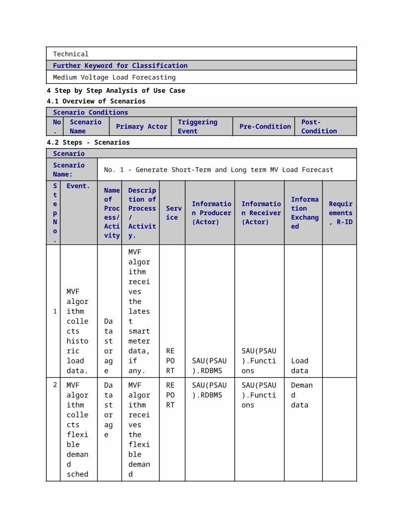
reconfiguration algorithm has finished.6) Validate Network Reconfiguration outputs: Outputs are sent to the CCDXP and MV IEDs.7) In case of congestion problems, Run Market Agent: Execute Market Agent algorithm .8) Validate Market Agent outputs: Outputs are sent to the CCDXP and CAs.
9) Finish Tertiary controller execution.
1.5 General RemarksGeneral Remarks
2 Diagrams of Use Case
3 Technical Details3.1 Actors
ActorsGrouping Group Description
Actor Name Actor Type Actor DescriptionFurther information specific to this Use Case
DMS.MMSfunction Data exchange platform of DMS
MMS client server interface

DMS.WS function DXP of DMS for webservices
DMS.functions function Power control functions
DMS.functionsfunction DMS
Network reconfiguration
DMS.RDBMS function Database of DMS
SAU(PSAU).MMS
function MMS interface
IED(PSIED).MMS function MMS interface
CA.WS
function Commercial aggregator offers services to aggregate energy production from different sources (generators) and acts towards the grid as one entity, including local aggregation of demand (Demand Response management) and supply (generation management). In cases where the aggregator is not a supplier, it maintains a contract with the supplier.
DMS.functions
function Distribution System Operator - Technical Aggregator (DSO. Technical aggregator)
according to the Article 2.6 of the Directive: "a natural or legal person responsible for operating, ensuring the maintenance of and, if necessary, developing the distribution system in a given area and, where applicable, its interconnections with other systems and for ensuring the long-term ability of the system to meet reasonable demands for the distribution of electricity". Moreover, the DSO is responsible for regional grid access and grid stability, integration of renewables at the distribution level and regional load balancing.
3.2 Triggering Event, Preconditions, AssumptionsUse Case ConditionsActor/System/Information/Contract
Triggering Event
Pre-conditions Assumption
3.3 ReferencesReferences
No. References Type Reference Statu
sImpact on Use Case
Organistaor / Organisation
Link
3.4 Further Information to the Use Case for Classification / Mapping

Classification InformationRelation to Other Use CasesLevel of DepthPriorisationGeneric, Regional or National RelationViewpointFurther Keyword for Classification
4 Step by Step Analysis of Use Case4.1 Overview of Scenarios
Scenario ConditionsNo.
Scenario Name Primary Actor Triggering Event Pre-Condition Post-Condition
4.2 Steps - ScenariosScenarioScenario Name: No. 1 - Normal Sequence
Step No.
Event.Name of Process/ Activity
Description of Process/ Activity.
Service
Information Producer (Actor)
Information Receiver (Actor)
Information Exchanged
Requirements, R-ID
1
CCPC asks CC DXP if data has been updated
Check flag
CCPC asks CC DXP if data has been updated
EXECUTE
DMS.functions
DMS.RDBMS
Is data updated-Request
2
CC DXP confirms whether data has been updated
Check flag
CC DXP confirms whether data has been updated
REPORT
DMS.RDBMS
DMS.functions
Is data updated-Reply
3
Read updated topology and parameters from CC DXP
Data storage
Read updated topology and parameters from CC DXP
EXECUTE
DMS.RDBMS
DMS.functions
Static Grid Data
4 Read MV Load demand (active/reactive) forecast (24h day
Data storage
Read MV Load demand (active/reactive) forecast (24h day
EXECUTE
DMS.RDBMS
DMS.functions
long term load and production forecast

ahead), MV production forecast (24h day ahead)
ahead), MV production forecast (24h day ahead)
5
CCPC takes the information relative to the available flexibility in the MV grid and its price (SRPs)
Data storage
CCPC takes the information relative to the available flexibility in the MV grid and its price (SRPs)
EXECUTE
DMS.RDBMS
DMS.functions
Bid for SRP
6
Run power flow to check the feasibility of Provisional schedule (hourly based) after the market clearing
Power flow
Run power flow to check the feasibility of Provisional schedule (hourly based) after the market clearing
EXECUTE
DMS.functions
DMS.functions
Power flow validation results
7
CCPC sends its outputs into CCDXP
Data storage
CCPC sends its outputs into CCDXP
EXECUTE
DMS.functions
DMS.RDBMS
Power flow validation results
8 Medium voltage network reconfiguration UC. In
Medium voltage network reconfiguration UC
Medium voltage network reconfiguration UC. In
EXECUTE
DMS.functions
DMS.RDBMS
Switch State Schedule
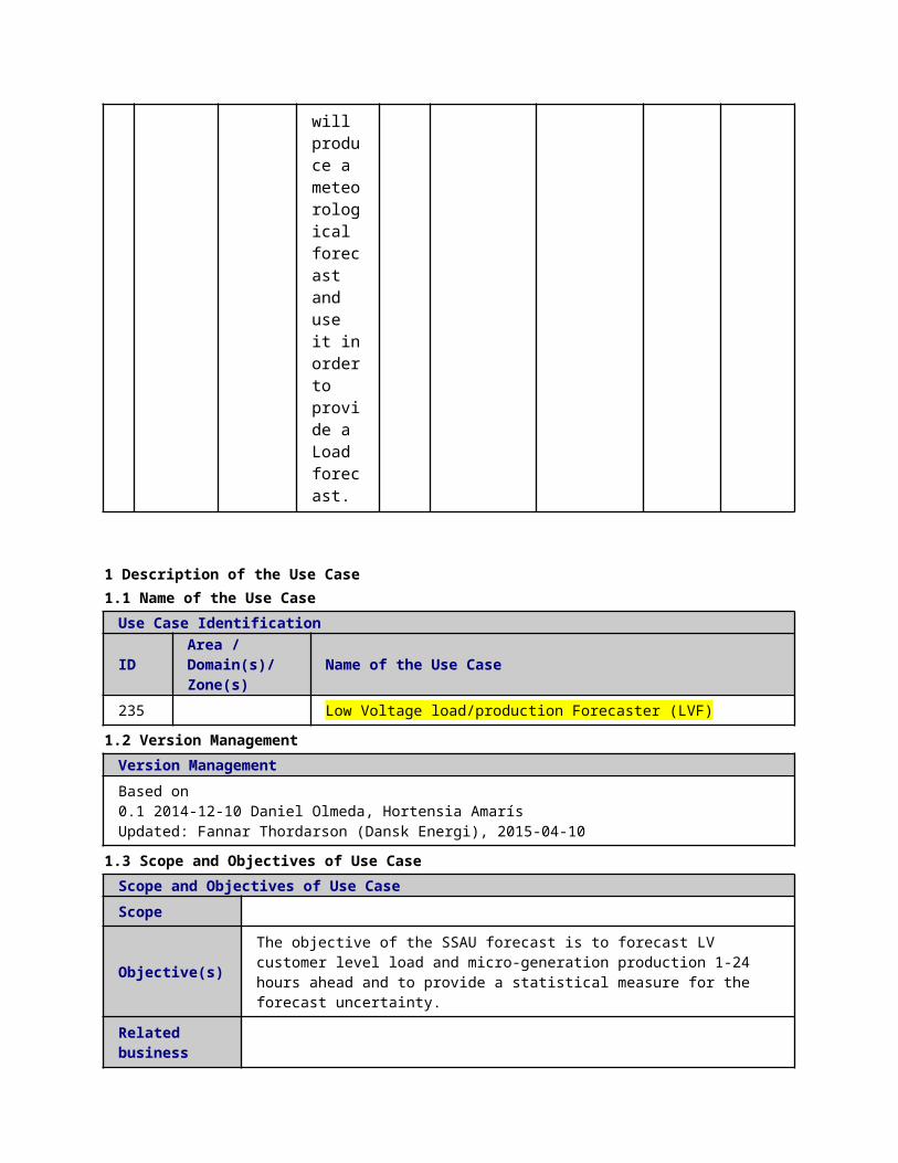
case of congestion problems, CCPC request the execution of the NR algorithm Calculate the optimal network configuration and/or voltage control set-points to alleviate MV congestion problems
case of congestion problems, CCPC request the execution of the NR algorithm Calculate the optimal network configuration and/or voltage control set-points to alleviate MV congestion problems
9
CCPC sends open/close commands to the modified IEDs controlling the switches
Reading/Writing IEDs setting
CCPC sends open/close commands to the modified IEDs controlling the switches
REPORT
DMS.MMS
SAU(PSAU).MMS
Switch State Schedule Setting Values of IEDs
10
MVIEDs confirm the new settings to the CCPC
Check flag
MVIEDs confirm the new settings to the CCPC
REPORT
IED(PSIED).MMS
SAU(PSAU).MMSDMS.MMS
Is data updated-Reply
1 Run Power Run EXE DMS.fun DMS.fun Power
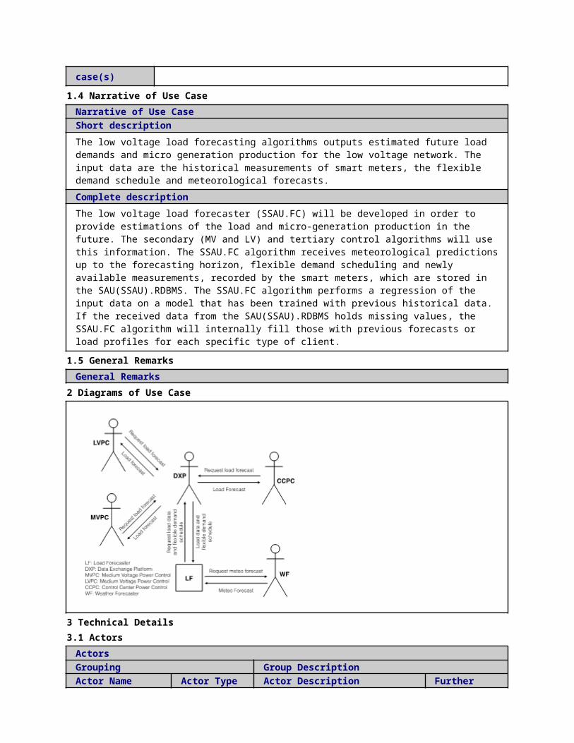
1
power flow to check the feasibility of Provisional schedule (hourly based) after the market clearing flow
power flow to check the feasibility of Provisional schedule (hourly based) after the market clearing
CUTE ctions ctions
flow validation results
12
CCPC sends its outputs into CCDXP if there are not MV congestion problems. Otherwise the exectution of the market agent algorithm is required
Data storage
CCPC sends its outputs into CCDXP if there are not MV congestion problems. Otherwise the exectution of the market agent algorithm is required
REPORT
DMS.functions
DMS.RDBMS
Activation flag
13
CCPC sends its outputs into CCDXP if there are not MV congestion problems.
Data storage
CCPC sends its outputs into CCDXP if there are not MV congestion problems.
REPORT
DMS.functions
DMS.RDBMS
Power flow validation results

Otherwise the exectution of the market agent algorithm is required
Otherwise the exectution of the market agent algorithm is required
14 Off line
validation UC
Off line validation UC
Off line validation UC
EXECUTE
DMS.RDBMS
DMS.functions
Bid Acceptance or Modification
15
CCPC runs the OPF to select the optimal flexibility offer solving the congestion
Optimal power flow
CCPC runs the OPF to select the optimal flexibility offer solving the congestion
EXECUTE
DMS.functions
DMS.functions
OPF result
16
MA results are exported to CC DXP
Data storage
MA results are exported to CC DXP
REPORT
DMS.functions
DMS.RDBMS
OPF result
17
Send commands to CAs. Communicate MA results (accepted flexibility offer and final schedule
CRP activation UC
Send commands to CAs. Communicate MA results (accepted flexibility offer and final schedule
REPORT
DMS.WS CA.WS Power schedule
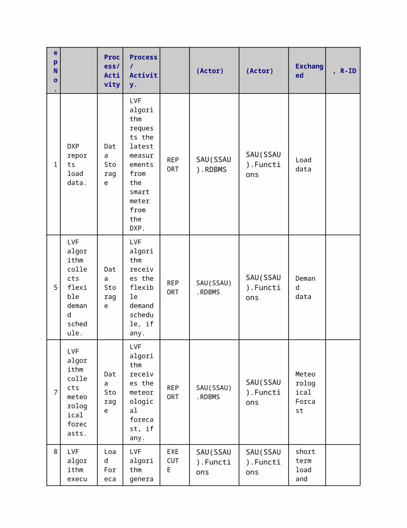
) to Commercial aggregators, including load shedding if needed.
) to Commercial aggregators, including load shedding if needed.
5 Information ExchangedInformation ExchangedName of Information (ID)
Description of Information Exchanged Requirements to information data
Activation flag
Is data updated-Reply
Is data updated-Request
Static Grid Data
Data exchanged:- Line parameters (R, X, B, G)- Line connections- Location of swithes, breakers and fuses- Transformer parameters
State Estimation results node voltages, line currents etc.
Bid for SRP
long term load and production forecast
Valid for the next 24 hours
OPF result optimal power flow calculation
Power flow validation results
Switch State Schedule
Setting Values of IEDs
Bid Acceptance or Modification
In case the bids can not be validated, due to network constraints violation, a modification is requested, else they are accepted.It contains a curtailment factor. So that the commercial aggregator can apply that CRP with a certain Delta P
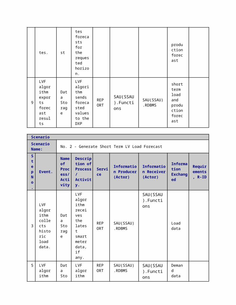
Power scheduleProvisional schedule.Planned schedulesPower + time (positive or negative)
1 Description of the Use Case1.1 Name of the Use Case
Use Case Identification
IDArea / Domain(s)/Zone(s)
Name of the Use Case
254 Control Centre Power Control (CCPC): Real Time Operation
1.2 Version ManagementVersion Management
1.3 Scope and Objectives of Use CaseScope and Objectives of Use Case
ScopeThe CCPC is part of a more general scheme called “Congestion Managementâ€. The CCPC working on real time tries to solve MV network �congestions which appear during real time operation which corresponds to post-fault situations and MVPC request.
Objective(s)The objective of the CCPC is to solve MV congestions for the next hour by means of distribution asset resources or by network reconfiguration and market based methods.
Related businesscase(s)
1.4 Narrative of Use CaseNarrative of Use CaseShort descriptionThe primary objective of the CCPC working on real time is to define and develop functions for the congestion management of MV distribution network. These functions are implemented on control centre level to manage MV networks by means of:
Network related measures, in particular through network circuit reconfiguration and changes of the setting values of voltage controllers in the MV network and reactive power units. Market related measures to propose changes of scheduled generation/consumption values of DER units, through flexibility products to provide a feasible combination of schedules.
These functionalities can be obtained by means of two different algorithms: Network Reconfiguration and Market Agent algorithms.
Complete descriptionCongestions appearing in the distribution grid (MV level) during real time operation (e.g.: Post-fault situations and MVPC requests) should be solved first through the DSO distribution asset resources or by network reconfiguration. If these actions are insufficient to solve the congestions, or are not practicable, then the purchase of flexibility products from Commercial Aggregators (CAs) is evaluated through the Market Agent tool.
The main program running the CCPC algorithm on real time can be divided into the following steps:1. Initialization: “Fast Restoration Complete” signal/message or request message from MVPC is received.2. Check MV grid constraints: Run power flow to check the feasibility of the switches status once the Fast Restoration
Process is completed.3. Validate inputs data: Validate if the initial switches status received from WP4 (after the FLISR process) do not
produce any congestion at MV network. Outputs are sent to the CCDXP and MV IEDs.4. Send request message to NR: in case of congestion problems the tertiary controller manager will send a request
message to the NR to execute the network reconfiguration algorithm.5. Receive message from NR: Tertiary controller manager will receive a message from NR as soon as the Network
reconfiguration algorithm has finished. The message from NR can be: “Modified switches status” if the congestion problem has been solved by the network reconfiguration algorithm or “Finished” if NR is not capable to find out a solution by network reconfiguration.
6. Validate Network Reconfiguration outputs: Outputs are sent to the CCDXP and MV IEDs.7. Run Market Agent: Execute Market Agent algorithm if NR message is “Finished”.
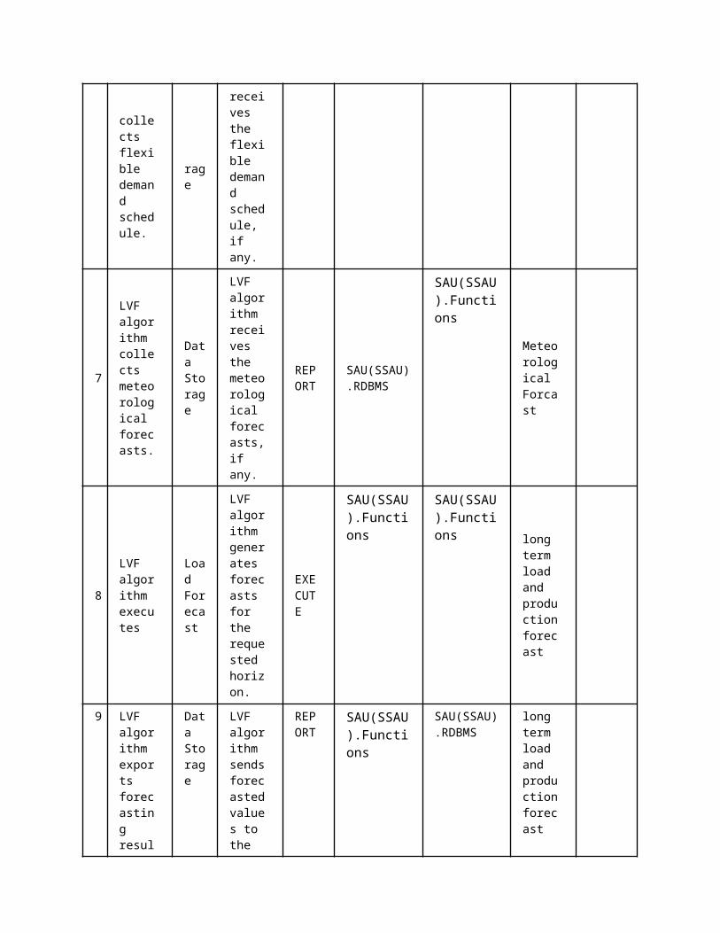
8. Validate Market Agent outputs: Outputs are sent to the CCDXP and CAs. 9. Finish Tertiary controller execution.
1.5 General RemarksGeneral Remarks
2 Diagrams of Use Case
3 Technical Details3.1 Actors
ActorsGrouping Group Description
Actor Name Actor Type Actor DescriptionFurther information specific to this Use Case
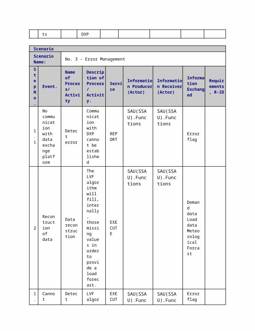
DMS.functions function DMS Power control
CA.WS
function offers services to aggregate energy production from different sources (generators) and acts towards the grid as one entity, including local aggregation of demand (Demand Response management) and supply (generation management). In cases where the aggregator is not a supplier, it maintains a contract with the supplier.
SAU(PSAU).MMS
functionMMS Interface
DMS.RDBMS function Database of DMS
DMS.functions
function Distribution System Operator - Technical Aggregator (DSO. Technical aggregator)
according to the Article 2.6 of the Directive: "a natural or legal person responsible for operating, ensuring the maintenance of and, if necessary, developing the distribution system in a given area and, where applicable, its interconnections with other systems and for ensuring the long-term ability of the system to meet reasonable demands for the distribution of electricity". Moreover, the DSO is responsible for regional grid access and grid stability, integration of renewables at the distribution level and regional load balancing.
IED(PSIED).MMS function IED MMS interface
DMS.functionsfunction DMS
Network reconfiguration
DMS.WS function DXP of DMS for webservices
MOP
function The unique power exchange of trades for the actual delivery of energy that receives the bids from the Balance Responsible Parties that have a contract to bid. The market operator determines the market energy price for the market balance area after applying technical constraints from the system operator. It may also establish the price for the reconciliation within a metering grid area.

DMS.MMSfunction Data exchange platform of DMS
MMS client server interface
3.2 Triggering Event, Preconditions, AssumptionsUse Case ConditionsActor/System/Information/Contract
Triggering Event
Pre-conditions Assumption
3.3 ReferencesReferences
No. References Type Reference Statu
sImpact on Use Case
Organistaor / Organisation
Link
3.4 Further Information to the Use Case for Classification / MappingClassification InformationRelation to Other Use CasesLevel of DepthPriorisationGeneric, Regional or National RelationViewpointFurther Keyword for Classification
4 Step by Step Analysis of Use Case4.1 Overview of Scenarios
Scenario ConditionsNo.
Scenario Name Primary Actor Triggering Event Pre-Condition Post-Condition
4.2 Steps - ScenariosScenarioScenario Name: No. 1 - Normal Sequence
Step No.
Event.Name of Process/ Activity
Description of Process/ Activity.
Service
Information Producer (Actor)
Information Receiver (Actor)
Information Exchanged
Requirements, R-ID
1 Activation CCPC due to Post fault situations (Fast Restoration Process is completed) or MVPC signal
Check flag
Activation CCPC due to Post fault situations (Fast Restoration Process is completed) or MVPC signal
REPORT
DMS.RDBMS
DMS.functions Activation flag

request request
2
CCPC asks CC DXP if data has been updated
Check flag
CCPC asks CC DXP if data has been updated
REPORT
DMS.functions DMS.RDBMS
Is data updated-Request
3
CC DXP confirms whether data has been updated
Check flag
CC DXP confirms whether data has been updated
REPORT
DMS.RDBMS DMS.functions
Is data updated-Reply
4
Import grid data.Read updated grid data (topology and parameters) from CC DXP
Data storage
Import grid data.Read updated grid data (topology and parameters) from CC DXP
REPORT
DMS.RDBMS DMS.functions
Static Grid Data
5 Get Load demand and power Production states. Read Active and Reactive power (state estimator) for all MV nodes, MV/LV
Data storage
Get Load demand and power Production states. Read Active and Reactive power (state estimator) for all MV nodes, MV/LV
REPORT
DMS.RDBMS
DMS.functions State Estimation results
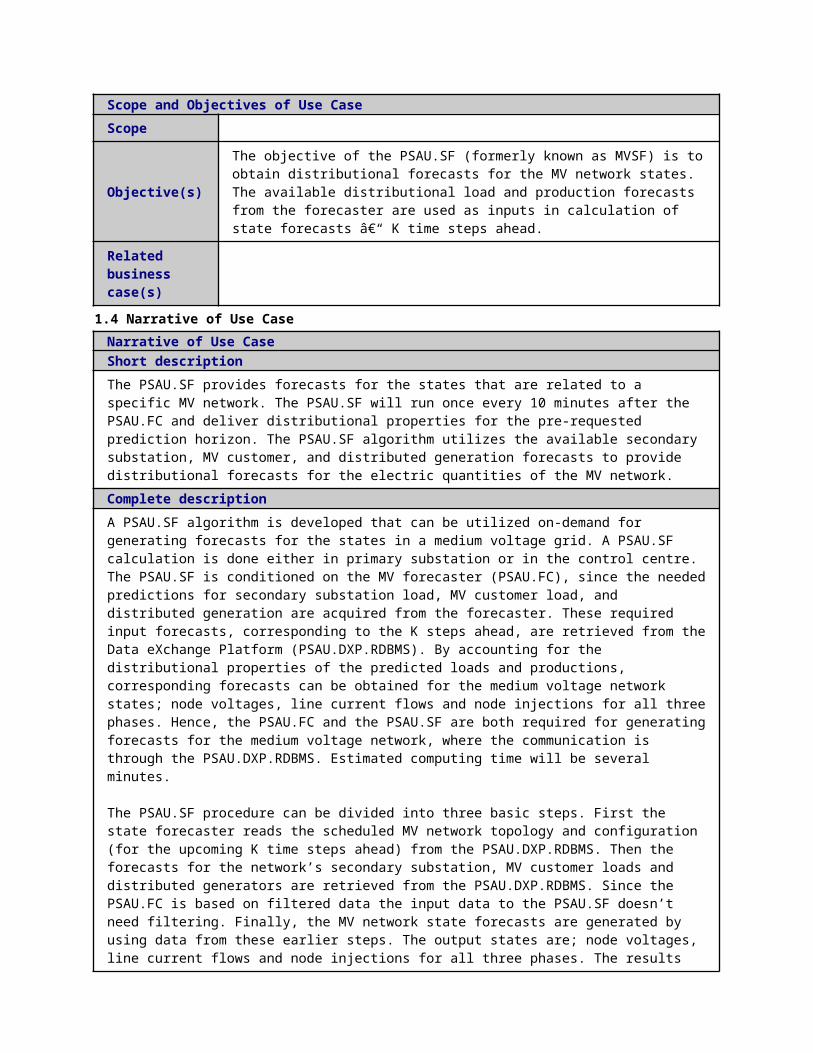
aggregated substation load demand (active/reactive)
aggregated substation load demand (active/reactive)
6
Get Load demand and power Production forecast. Read MV Load demand (active/reactive) forecast (k steps ahead), MV production forecast (k-steps ahead)
Data storage
Get Load demand and power Production forecast. Read MV Load demand (active/reactive) forecast (k steps ahead), MV production forecast (k-steps ahead)
REPORT
DMS.RDBMS DMS.functions
short term load and production forecast
7
Read flexibility offers (SRPs) and activation parameters of CRPs
Data storage
Read flexibility offers (SRPs) and activation parameters of CRPs
REPORT
DMS.RDBMS DMS.functions
Volumes and prices of SRPs activation parameters of contracted CRPs
8 PF Power PF EX DMS.fu DMS.functions Power

Validation. Run power flow to check the feasibility of the switches status once the Fast Restoration Process is completed or MVPC signal has been received flow
Validation. Run power flow to check the feasibility of the switches status once the Fast Restoration Process is completed or MVPC signal has been received
ECUTE nctions
flow validation results
9 Evaluate PF validation. CCPC sends its outputs into CCDXP if there are not MV congestion problems. If there are problems "Network reconfiguration
Data storage
Evaluate PF validation. CCPC sends its outputs into CCDXP if there are not MV congestion problems. If there are problems "Network reconfiguration is
EXECUTE
DMS.functions
DMS.RDBMS Activation flag Power flow validation results

is activated"
activated"
10
NR use case. Calculate the optimal network configuration and/or voltage control set-points to alleviate MV congestion problems
Medium voltage network reconfiguration UC
NR use case. Calculate the optimal network configuration and/or voltage control set-points to alleviate MV congestion problems
EXECUTE
DMS.functions DMS.RDBMS
Activation flag Switch State Schedule
11
Send commands to MVIEDs. CCPC sends open/close commands to the modified IEDs controlling the switches
Reading/Writing IEDs setting
Send commands to MVIEDs. CCPC sends open/close commands to the modified IEDs controlling the switches
REPORT
DMS.MMS
SAU(PSAU).MMSIED(PSIED).MMS
Setting Values of IEDs
Switch State Schedule
12
MVIEDs confirm the new settings to the CCPC
Reading/Writing IEDs setting
MVIEDs confirm the new settings to the CCPC
REPORT
IED(PSIED).MMS
DMS.MMSSAU(PSAU).MMS
Is data updated-Reply
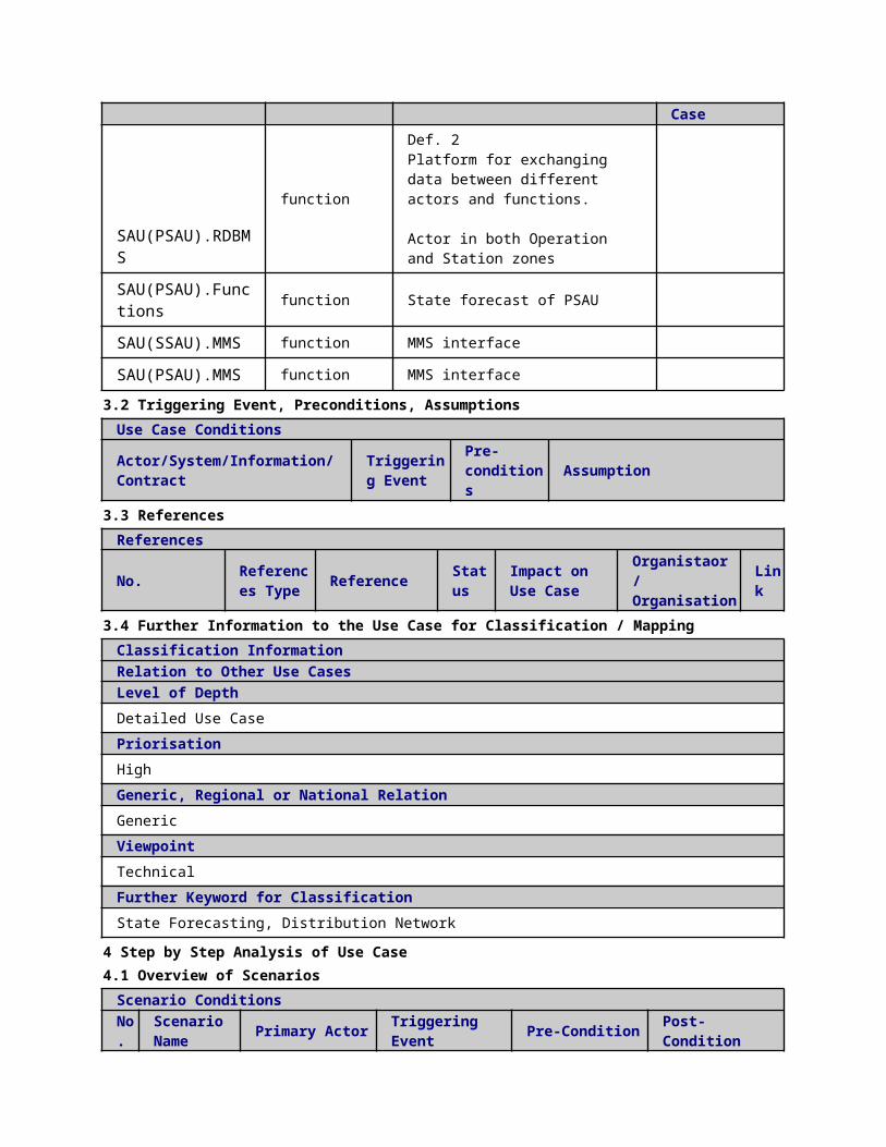
12
MVIEDs confirm the new settings to the CCPC
Reading/Writing IEDs setting
MVIEDs confirm the new settings to the CCPC
REPORT
DMS.RDBMS DMS.MMS
Is data updated-Reply
13
PF Validation. Run power flow to check the feasibility of the switches status once the Fast Restoration Process is completed or MVPC signal has been received
Power flow
PF Validation. Run power flow to check the feasibility of the switches status once the Fast Restoration Process is completed or MVPC signal has been received
EXECUTE
DMS.functions DMS.functions
Power flow validation results
14
Evaluate PF validation. CCPC sends its outputs into CCDXP if there are not MV congestion problems. If
Check flag
Evaluate PF validation. CCPC sends its outputs into CCDXP if there are not MV congestion problems. If there
EXECUTE
DMS.functions
DMS.functions Activation flag Power flow validation results

there are problems "Network reconfiguration is activated"
are problems "Network reconfiguration is activated"
14
Evaluate PF validation. CCPC sends its outputs into CCDXP if there are not MV congestion problems. If there are problems "Network reconfiguration is activated"
Data storage
Evaluate PF validation. CCPC sends its outputs into CCDXP if there are not MV congestion problems. If there are problems "Network reconfiguration is activated"
EXECUTE
DMS.functions DMS.RDBMS
Activation flag Power flow validation results
15
Request to MA execution (RTV algorithm).In case of congesti
Real time validation UC
Request to MA execution (RTV algorithm).In case of congesti
REPORT
DMS.RDBMS
DMS.functions Bid Acceptance or Modification

on problems not solved by the NR, CCPC request the execution of the Market Agent algorithm (Real Time Validation algorithm)
on problems not solved by the NR, CCPC request the execution of the Market Agent algorithm (Real Time Validation algorithm)
16
OPF Calculation. CCPC runs the OPF to select the optimal flexibility solving the congestion: activation of CRPs or the purchase of new SRPs
Optimal power flow
OPF Calculation. CCPC runs the OPF to select the optimal flexibility solving the congestion: activation of CRPs or the purchase of new SRPs
REPORT
DMS.functions DMS.functions
OPF result
17
Evaluate PF validation.
Commercial optimal
Evaluate PF validation. CCPC
REPORT
DMS.functions
DMS.functions Bid for SRP
ON/
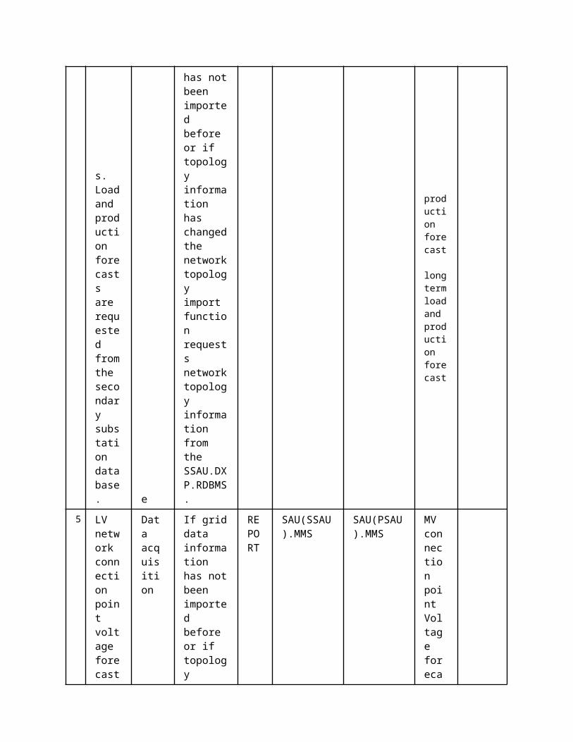
CCPC sends its outputs into CCDXP if there are not MV congestion problems. If there are problems it saves he accepted flexibility offer and/or the activated CRP to Commercial aggregators (or prosumers
planning
sends its outputs into CCDXP if there are not MV congestion problems. If there are problems it saves he accepted flexibility offer and/or the activated CRP to Commercial aggregators (or prosumers
OFF CRP
18
Export results SRP, CRP to database of DMS
Data storage
Export results SRP, CRP to database of DMS
REPORT
DMS.functions DMS.RDBMS
Bid for SRP
ON/OFF CRP
19
Trade of SRP bids in electrical market
SRP day-ahead and intra-day market procur
Trade of SRP bids in electrical market
REPORT
DMS.WS
MOP Bid for SRP
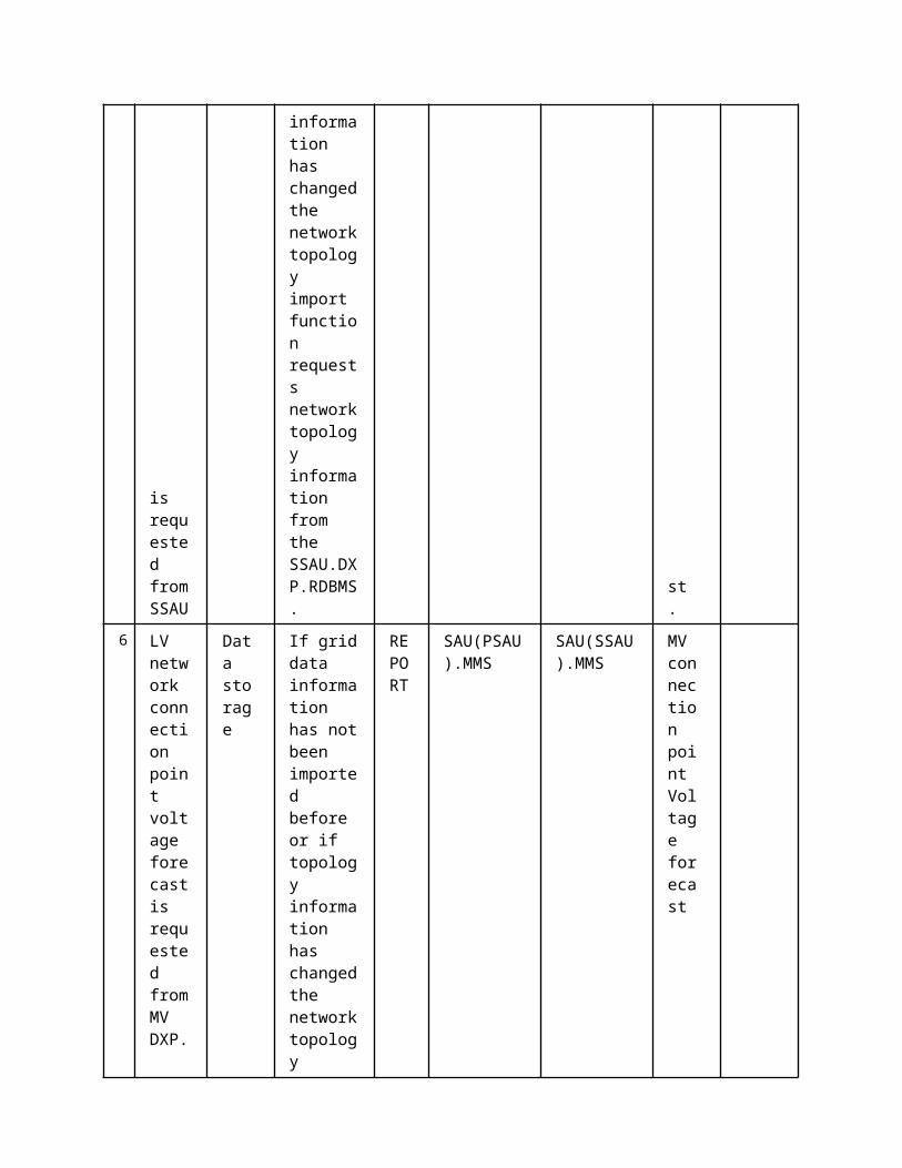
ement UC
20
Send activation of CRP commands to CAs.Communicate the accepted flexibility offer and/or the activated CRP to Commercial aggregators (or prosumers), including load shedding if needed.
CRP activation UC
Send activation of CRP commands to CAs.Communicate the accepted flexibility offer and/or the activated CRP to Commercial aggregators (or prosumers), including load shedding if needed.
REPORT
DMS.WS CA.WS
ON/OFF CRP
5 Information ExchangedInformation ExchangedName of Information (ID)
Description of Information Exchanged Requirements to information data
Activation flag
Is data updated-Request
Is data updated-Reply
Static Grid Data
Data exchanged:- Line parameters (R, X, B, G)- Line connections- Location of swithes, breakers and fuses- Transformer parameters
State Estimation results node voltages, line currents etc.
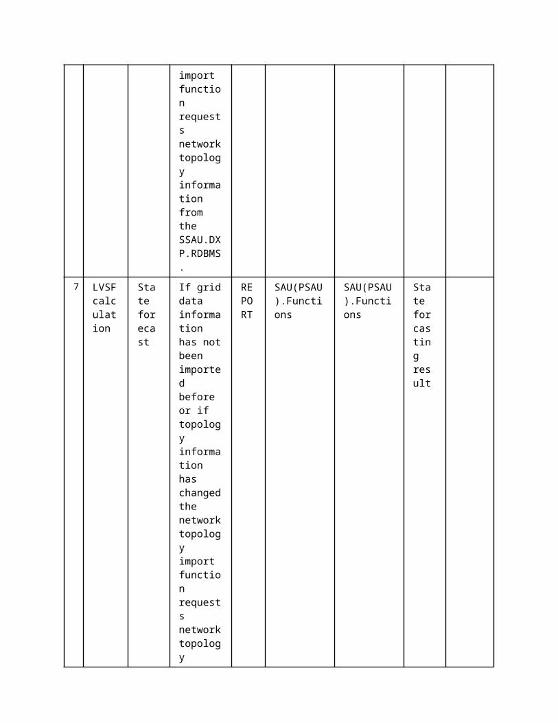
Volumes and prices of SRPs
Volumes and prices of Scheduled re profiling
activation parameters of contracted CRPs
Setting Values of IEDs
Switch State Schedule
Bid for SRP
ON/OFF CRP activate or deactivate conditional reprofiling product
short term load and production forecast
valid for the next 15-30 minutes
Power flow validation results
Bid Acceptance or Modification
In case the bids can not be validated, due to network constraints violation, a modification is requested, else they are accepted.It contains a curtailment factor. So that the commercial aggregator can apply that CRP with a certain Delta P
OPF result optimal power flow calculation
1 Description of the Use Case1.1 Name of the Use Case
Use Case Identification
IDArea / Domain(s)/Zone(s)
Name of the Use Case
237 Medium Voltage Network Reconfiguration
1.2 Version ManagementVersion ManagementFrom V1.0 15.12.2014 Mónica Alonso, Hortensia AmarÃs
1.3 Scope and Objectives of Use CaseScope and Objectives of Use CaseScope
Objective(s)The objective of the MVNR is to obtain the optimal MV network configuration by closing some normally open switches and opening some normally closed switches in order to reduce MV network congestions during normal or post-fault situations.
Related business

case(s)
1.4 Narrative of Use CaseNarrative of Use CaseShort descriptionMVNR update network switches status in order to alleviate congestion problems that are related to a specific MV network. The MVNR runs on demand and also run on fixed intervals such as once a day or scheduled hours to find the optimal configuration of the network. The MVNR algorithm utilizes switches state information (open/close), and the load and production forecast that are saved at the DXP.Complete descriptionIn normal operation the Network reconfiguration algorithm will be executed to reduce system losses, balance loads (exchange between feeders) and to avoid overload of network elements.
The main program running the network reconfiguration algorithm can be divided into the following steps: 1) Activation of trigger signals. The network reconfiguration algorithm runs on demand and also run on fixed intervals such as once a day or scheduled hours to find the optimal configuration of the network. So it would be executed whenever the activation trigger signals is activated.
2) Read Network topology and switch data position from the control centre level DXP. Two types of switches will be considered: normally closed switches which connect line sections (sectionalizing switches) and normally open switches on the tie-lines which connect two feeders.
3) Read Real-time measurement reading and/or state estimation outputs.
4) Topology information processing.
5) Optimal network reconfiguration execution. Network reconfiguration is a mixed integer non linear optimization problem containing both binary variables (operative status of switching devices, on/off) and continuous variables (branch currents, power injections and nodal voltages).
1.5 General RemarksGeneral Remarks
1. Basic Information to Use CaseSource(s) / Literature Link Conditions
(limitations) of Use
Tertiary Control: Network reconfiguration
https://wiki.tut.fi/pub/IDE4L/
designspecification-wp-5-2-3-network-reconfigurartion-
2nd_draft.docx
Internal (IDE4L)
2 Diagrams of Use Case
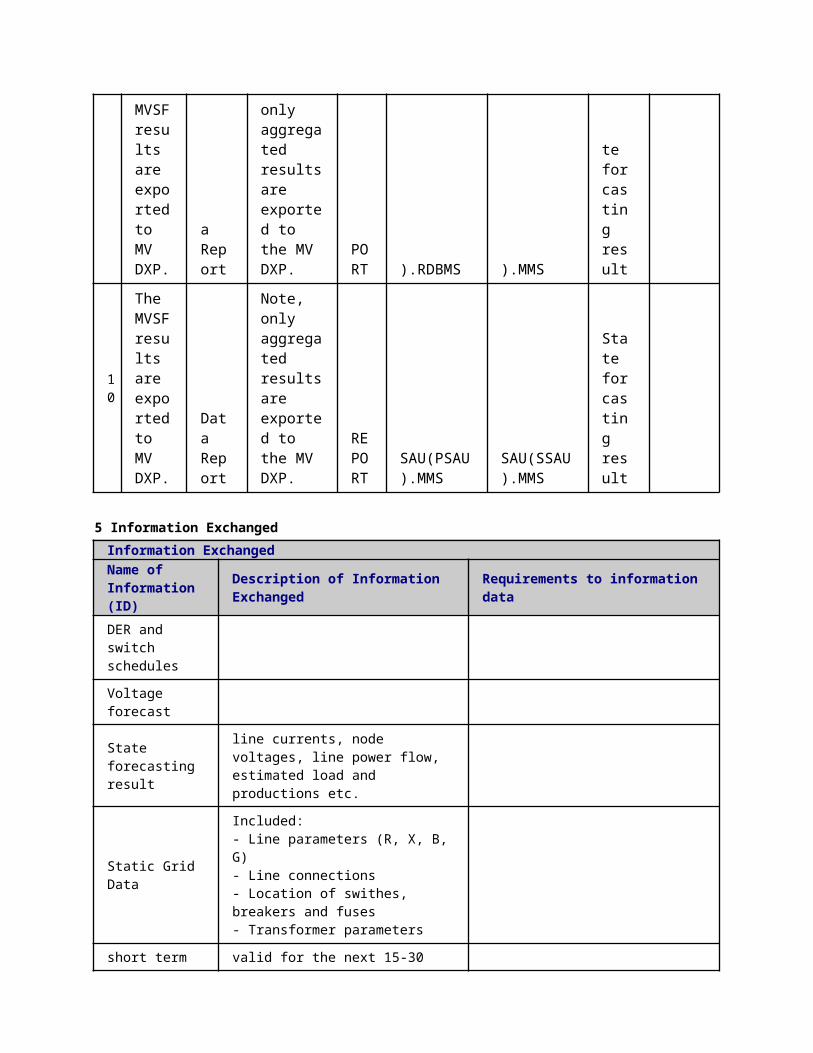

3 Technical Details3.1 Actors
ActorsGrouping Group Description
Actor Name Actor Type Actor DescriptionFurther information specific to this Use Case
DMS.RDBMS function
DMS.functions function DMSNetwork reconfiguration
3.2 Triggering Event, Preconditions, AssumptionsUse Case ConditionsActor/System/Information/Contract
Triggering Event
Pre-conditions Assumption
3.3 ReferencesReferences
No. References Type Reference Statu
sImpact on Use Case
Organistaor / Organisation
Link
3.4 Further Information to the Use Case for Classification / MappingClassification InformationRelation to Other Use CasesLevel of DepthPriorisationHighGeneric, Regional or National RelationGenericViewpointTechnicalFurther Keyword for ClassificationControl, Distribution Network
4 Step by Step Analysis of Use Case4.1 Overview of Scenarios
Scenario ConditionsNo.
Scenario Name Primary Actor Triggering Event Pre-Condition Post-Condition
4.2 Steps - ScenariosScenarioScenario Name: No. 1 - MVNR Started
Step No.
Event.Name of Process/ Activity
Description of Process/ Activity.
Service
Information Producer (Actor)
Information Receiver (Actor)
Information Exchanged
Requirements, R-ID
1 Activation of trigger
Data storage
Internal calcula
REPORT
DMS.RDBMS
DMS.functions
Switch State

signals. MVNR withdraw switches state schedule for the next K hours. tions
2
If topology information has not been imported before or if topology information has changed the network topology import function requests network topology information from the MV DXP.
Data storage
Internal calculations
REPORT
DMS.RDBMS
DMS.functions
Network Topology
4 Get load and production forecasts
Data storage
Internal calculations
REPORT
DMS.RDBMS
DMS.functions
short term load and production forecast long
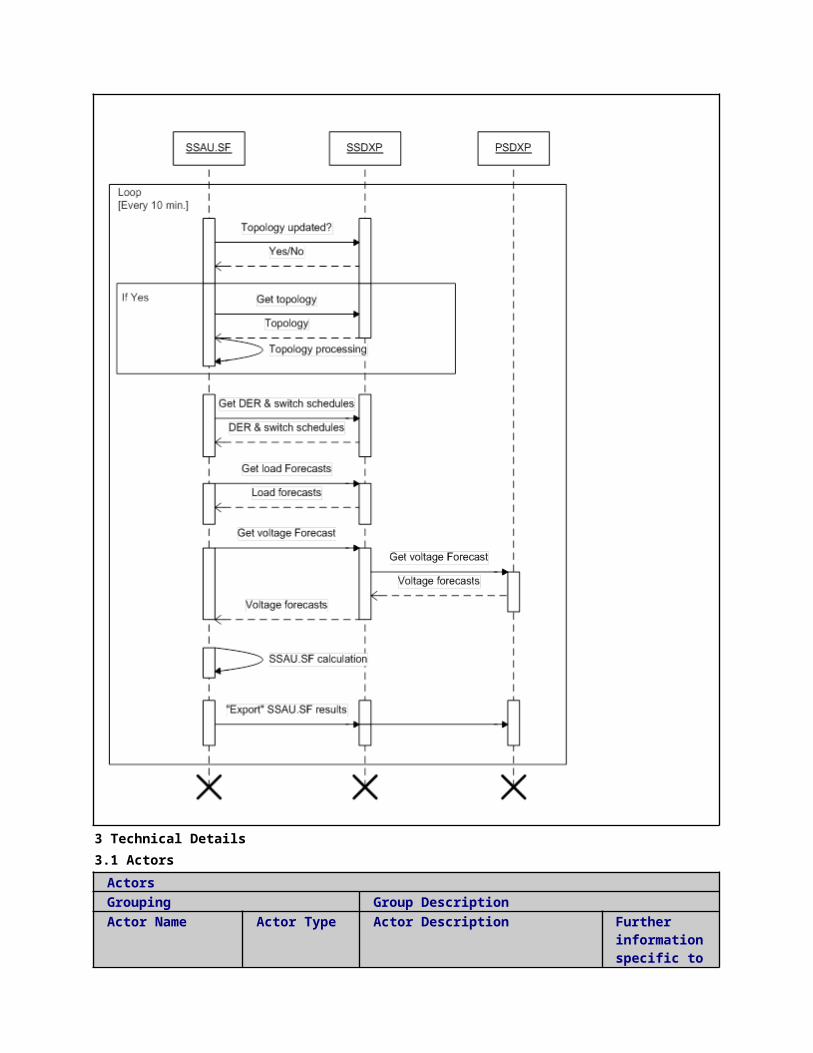
term load and production forecast
5
Get load and production forecasts
Data storage
Internal calculations
REPORT
DMS.RDBMS
DMS.functions
State Estimation results
6
Get load and production states. Active and reactive power MV Load demand and Active and reactive power MV injected power from DER are requested from the MV DXP.
Data storage
Internal calculations
REPORT
DMS.RDBMS
DMS.functions
Switch State Schedule
7 MVNR calculation. Calculate the optimal network configuration to
Medium voltage network reconfiguration UC
Internal calculations
REPORT
DMS.functions
DMS.functions
Switch State Schedule
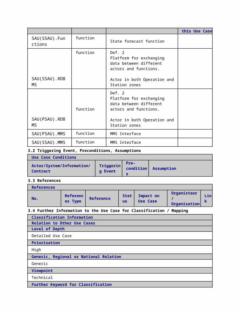
alleviate MV congestion problems.
5 Information ExchangedInformation ExchangedName of Information (ID)
Description of Information Exchanged Requirements to information data
Switch State
Network Topology
Switch State Schedule
short term load and production forecast
valid for the next 15-30 minutes
long term load and production forecast
Valid for the next 24 hours
State Estimation results node voltages, line currents etc.
1 Description of the Use Case1.1 Name of the Use Case
Use Case Identification
IDArea / Domain(s)/Zone(s)
Name of the Use Case
238 Medium Voltage Network Power Control (MVPC) Offline Cost Parameter Update
1.2 Version ManagementVersion ManagementFrom Version 1.2.: Minor modifications based on Jasmin’s comments. 9.2.2015 Author: Farzad Azimzadeh Moghaddam (TUT) Reviewer: Anna Kulmala
1.3 Scope and Objectives of Use CaseScope and Objectives of Use Case
ScopeThe MVPC in offline operation is part of a more general scheme called “Congestion Managementâ€. The MVPC (offline) tries to control and �optimize the power flow in future states of the MV network.
Objective(s)The objective of the offline MVPC is to utilize the medium voltage state forecaster (MVSF) information to define the value of cost parameters and prevent extra control actions (e.g. to decrease the number of tap changer operations in the future states of the network).

Related businesscase(s)
1.4 Narrative of Use CaseNarrative of Use CaseShort descriptionThis use case demonstrates how the offline MVPC interacts with other actors in order to define the value of cost parameters and prevent extra control actions (e.g. to decrease the number of tap changer operations in the future states of the network).Complete descriptionThe main functionality of the offline MVPC is to define cost parameters to avoid extra actions. For instance, it prevents constant operation i.e. hunting of transformer tap changers by changing the cost parameters of the real-time MVPC.
For defining the cost parameters, the offline MVPC requires interacting with other actors. The actors directly interacting with offline MVPC (PSAU.PCPU application) are the following:
Primary Substation Automation Unit Data Exchange Platform (PSAU.DXP) where offline MVPC reads all necessary inputs and writes changes of OPF cost parameters.
The actors updating necessary data in the PSAU.DXP to be further used by offline MVPC are as following:
Primary Substation Automation Unit State Forecaster (PSAU.SF) Control Centre Topology Manager (DMS.TM)
This use case presents the required interfaces for operation of the offline MVPC.
1.5 General RemarksGeneral Remarks
2 Diagrams of Use Case
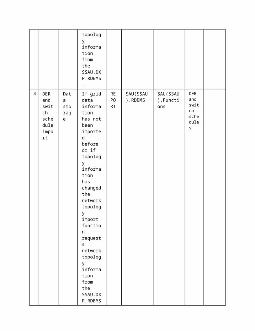
3 Technical Details3.1 Actors
ActorsGrouping Group Description
Actor Name Actor Type Actor DescriptionFurther information specific to this Use Case
SAU(PSAU).Functions
functionPrimary Substation Automation Unit Power Control Offline Cost Parameter Updator
SAU(PSAU).RDBMS function PSAU Data Exchange Platform
3.2 Triggering Event, Preconditions, AssumptionsUse Case ConditionsActor/System/Information/Contract
Triggering Event
Pre-conditions Assumption
3.3 ReferencesReferences
No. References Type Reference Statu
sImpact on Use Case
Organistaor / Organisation
Link
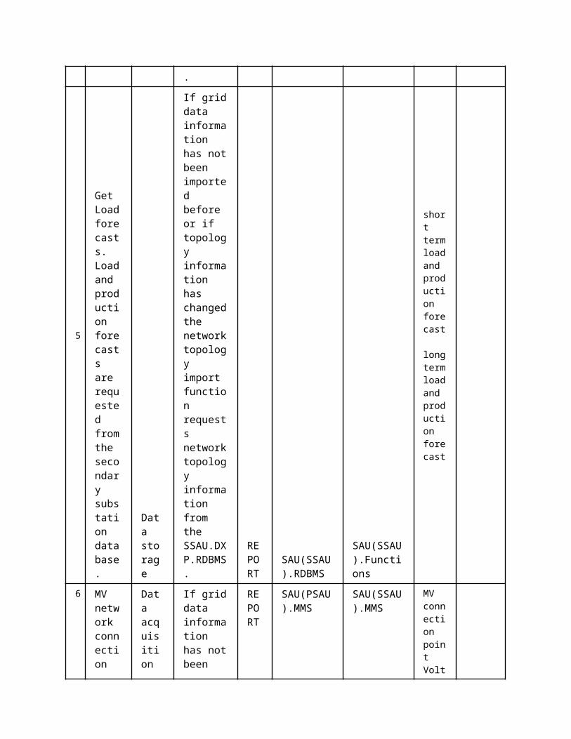
3.4 Further Information to the Use Case for Classification / MappingClassification InformationRelation to Other Use CasesLevel of DepthPriorisationHighGeneric, Regional or National RelationGenericViewpointTechnicalFurther Keyword for ClassificationDistribution grid management...
4 Step by Step Analysis of Use Case4.1 Overview of Scenarios
Scenario ConditionsNo.
Scenario Name Primary Actor Triggering Event Pre-Condition Post-Condition
4.2 Steps - ScenariosScenarioScenario Name: No. 1 - PS1: Normal sequence
Step No.
Event.
Name of Process/ Activity
Description of Process/ Activity.
Service
Information Producer (Actor)
Information Receiver (Actor)
Information Exchanged
Requirements, R-ID
2
PSAU.PCPU asks PSAU.DXP if new data has been updated into PSAU.DXP
Check flag
internal calculations
EXECUTE
SAU(PSAU).Functions
SAU(PSAU).RDBMS
Is data updated-Request
3
MVDXP confirms the data update
Check flag
internal calculations
EXECUTE
SAU(PSAU).RDBMS
SAU(PSAU).Functions
Is data updated-Reply
4 MVPC ask for
Data
internal
EXECUT
SAU(PSAU).Functions
SAU(PSAU).RDBMS
Data import
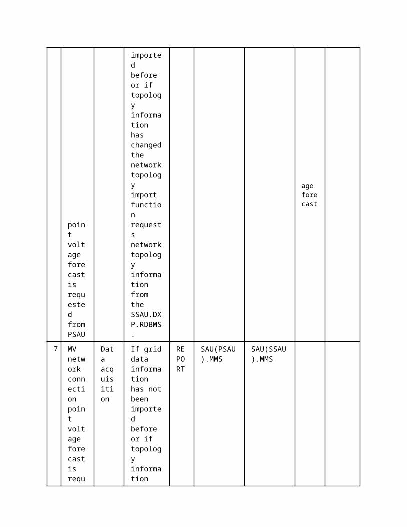
data import
storage
calculations E
request
5
PSAU.PCPU imports inputs(state forecasts, network data (topology and parameters)) from PSAU.DXP
Data storage
internal calculations
EXECUTE
SAU(PSAU).RDBMS
SAU(PSAU).Functions
Data for OPF calculation
6
OPF calculation for computing the cost parameters
Optimal power flow
Note: Depending on the time horizon used, the OPF will run several times to compute the cost parameters
EXECUTE
SAU(PSAU).Functions
SAU(PSAU).Functions
Data for OPF calculation Cost Parameters
7 OPF calculation for computing the cost
Optimal power flow
Note: Depending on the time horizon
EXECUTE
SAU(PSAU).Functions
SAU(PSAU).Functions
Cost Parameters
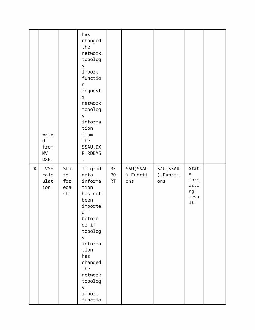
parameters
used, the OPF will run several times to compute the cost parameters
ScenarioScenario Name: No. 2 - AS1: OPF does not converge
Step No.
Event.
Name of Process/ Activity
Description of Process/ Activity.
Service
Information Producer (Actor)
Information Receiver (Actor)
Information Exchanged
Requirements, R-ID
1
Step 5 of the normal sequence has been successfully completed and OPF calculation of step 6 does not converge.PSAU.PCPU checks whether this happened also at the previous round
Detect error
Internal calculations
EXECUTE
SAU(PSAU).Functions
SAU(PSAU).RDBMS
Log message
2 If OPF converged. Stop PSAU.PCPU operation and wait for
Detect error
Internal calculations
EXECUTE
SAU(PSAU).Functions
SAU(PSAU).RDBMS
Log message

the next measurements to come in. Write a log message to the database.
3.1
if OPF did not converge at the previous round. Write a log message to the database.
Detect error
Internal calculations
EXECUTE
SAU(PSAU).Functions
SAU(PSAU).RDBMS
Log message
3.2
Send predetermined cost parameters to the PSAU.DXP
Data storage
Internal calculations
EXECUTE
SAU(PSAU).Functions
SAU(PSAU).RDBMS
Cost Parameters
ScenarioScenario Name: No. 3 - AS2: Proper input data is not available
Step No.
Event.
Name of Process/ Activity
Description of Process/ Activity.
Service
Information Producer (Actor)
Information Receiver (Actor)
Information Exchanged
Requirements, R-ID
1
if PSAU.PCPU was successful at the previous round
Detect error
Internal calculations
REPORT
SAU(PSAU).Functions
SAU(PSAU).RDBMS
State forecasting result
2 if PSAU.PCPU was not successful at the previous round.
Data storage
Internal calculations
REPORT
SAU(PSAU).Functions
SAU(PSAU).RDBMS
Log message
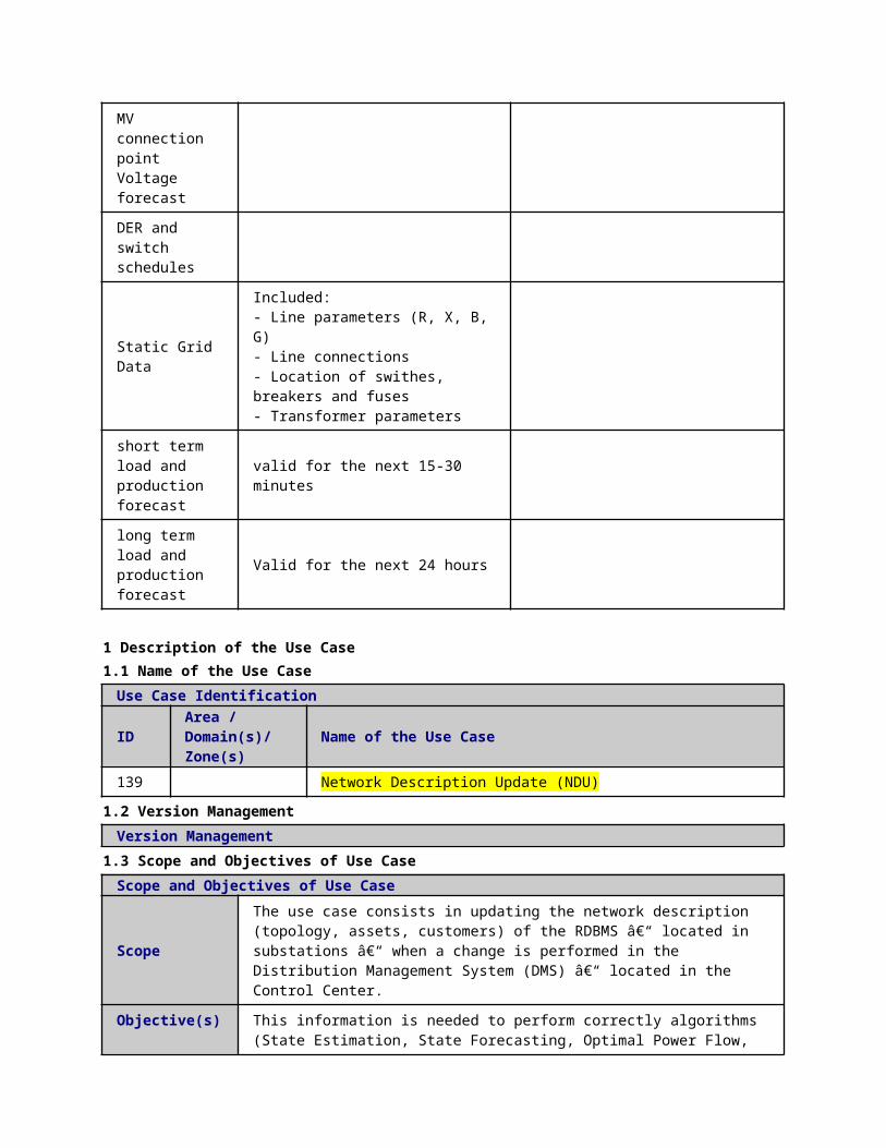
Send predetermined cost parameters to the PSAU.DXP.
3
if PSAU.PCPU was not successful at the previous round. Write a log message to the database
Detect error
Internal calculations
REPORT
SAU(PSAU).Functions
SAU(PSAU).RDBMS
Predetermined cost parameters
3.1
if PSAU.PCPU was successful at the previous round
Detect error
Internal calculations
REPORT
SAU(PSAU).Functions
SAU(PSAU).RDBMS
Log message
5 Information ExchangedInformation ExchangedName of Information (ID)
Description of Information Exchanged Requirements to information data
State forecasting result
line currents, node voltages, line power flow, estimated load and productions etc.
Data import request
Log message Log message
Predetermined cost parameters
Is data updated-Request
Is data updated-
Reply
Data for OPF calculation
PSAU.SF resultsNetwork data (topology and parameters)
Cost Parameters
cost of operation of on-load tap changers (OLTCs) etc.cost of generation curtailmentcost of demand response
6 Requirements (optional)Requirements (optional)
7 Common Terms and DefinitionsCommon Terms and DefinitionsTerm Definition
8 Custom Information (optional)Custom Information (optional)Key Value Refers to Section
1 Description of the Use Case1.1 Name of the Use Case
Use Case Identification
IDArea / Domain(s)/Zone(s)
Name of the Use Case
142 Medium Voltage Network Power Control (MVPC) in Real Time Operation
1.2 Version ManagementVersion ManagementFrom: Version 1.2 9.2.2015 Authors: Anna Kulmala and Farzad Azimzadeh Moghaddam (TUT)
Reviewers: Sami Repo and Jasmin Mehmedalic
1.3 Scope and Objectives of Use CaseScope and Objectives of Use Case
ScopeThe MVPC is part of a more general scheme called “Congestion Managementâ€. The MVPC tries to control and optimize the power flow in MV �network.
Objective(s) The objective of the MVPC is to utilize the medium voltage state estimation (MVSE) information to control and optimize the power flow in MV network.
Related businesscase(s)
1.4 Narrative of Use CaseNarrative of Use CaseShort descriptionThis use case demonstrates how the MVPC interacts with other actors in order to optimize and control the power flow in MV network.Complete description
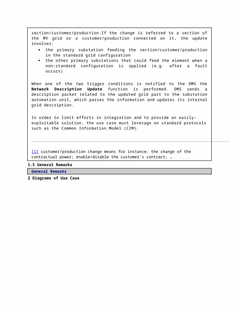
The main functionality of the MVPC is to mitigate congestion in the MV networks. The MVPC tries to reach and balance the following goals:
Reduction of the MV network losses Reduction of production curtailment Minimizing the load control actions and tap changer operations Reducing the cost of reactive power flow supplied by the transmission network Reducing the cost of active power flow supplied by the transmission network Reducing the voltage violation at each node
In order to reach the above-mentioned goals, the MVPC requires interacting with other actors. The actors directly interacting with MVPC (PSAU.PC application) are the following:
Primary Substation Automation Unit Data Exchange Platform (PSAU.DXP) where PC reads all necessary inputs and writes changes of IED settings.
The actors updating necessary data in the PSAU.DXP to be further used by MVPC are as follows: Control Centre Topology Manager (DMS.TM) Primary Substation Unit Block OLTC’s of Transformers (PSAU.BOT) Primary Substation Automation Unit Power Control Offline Cost Parameter Update (PSAU.PCPU) Primary Substation Automation Unit State Estimation (PSAU.SE) and complete medium voltage network real-time monitoring
use case providing necessary data to PSAU.SE Intelligent electronic devices (IEDs) located in the MV network where measurement data is received and control commands are
sent Secondary Substation Automation Unit Power Control (SSAU.PC)
This use case presents the required interfaces for operation of the MVPC.
1.5 General RemarksGeneral Remarks
1. Issues: Legal Contracts, Legal Regulations,Constraints and othersIssue - here specific ones
Impact of Issue on Use Case Reference – law, standard, others
Customer-owned distributed generations (DGs) metering information
Measurements from customer-owned DG units is required as input of the MVPC.
Information of customer’s controllable loads
This is required as input of the MVPC.
2 Diagrams of Use Case
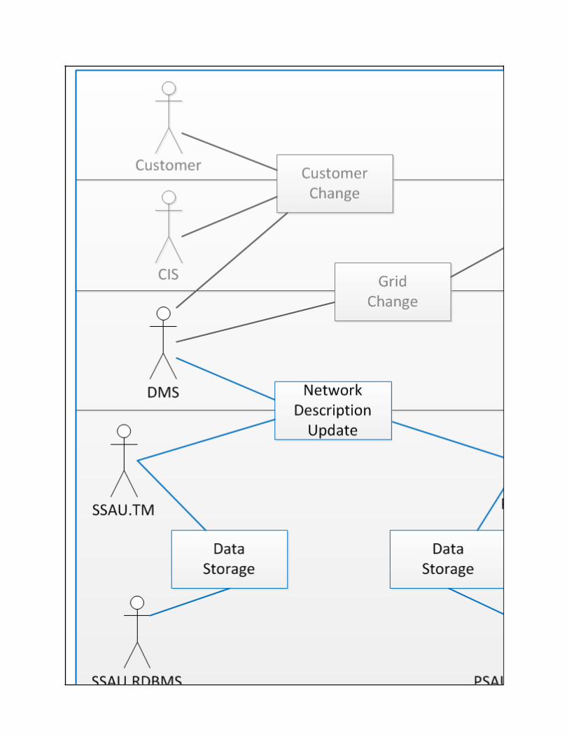
3 Technical Details3.1 Actors
ActorsGrouping Group Description
Actor Name Actor Type Actor DescriptionFurther information specific to this Use Case
IED(PSIED).MMS function IED MMS interface
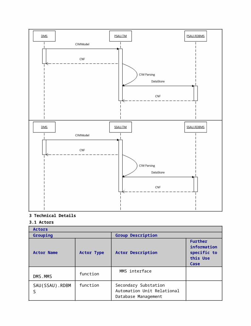
SAU(PSAU).RDBMS function PSAU Data Exchange Platform
SAU(PSAU).MMS function PSAU MMS interface
SAU(PSAU).Functions
function PSAU Power Control
3.2 Triggering Event, Preconditions, AssumptionsUse Case ConditionsActor/System/Information/Contract
Triggering Event
Pre-conditions Assumption
3.3 ReferencesReferences
No. References Type Reference Statu
sImpact on Use Case
Organistaor / Organisation
Link
3.4 Further Information to the Use Case for Classification / MappingClassification InformationRelation to Other Use CasesLow Voltage Network Power Control (LVPC) in Real Time Operation;Level of DepthPriorisationHighGeneric, Regional or National RelationGenericViewpointTechnicalFurther Keyword for ClassificationDistribution grid management...
4 Step by Step Analysis of Use Case4.1 Overview of Scenarios
Scenario ConditionsNo.
Scenario Name Primary Actor Triggering Event Pre-Condition Post-Condition
4.2 Steps - ScenariosScenarioScenario Name: No. 1 - Normal Sequence
Step No.
Event.Name of Process/ Activity
Description of Process/ Activity.
Service
Information Producer (Actor)
Information Receiver (Actor)
Information Exchanged
Requirements, R-ID
1 PSAU requests settings of MVIE
Reading/Writing IEDs setting
PSAU requests settings of MVIE
EXECUTE
SAU(PSAU).MMS
IED(PSIED).MMS
PSAU requests settings of MVIE

Ds Ds Ds
2
MVIEDs send value of their settings to SAU
Reading/Writing IEDs setting
MVIEDs send value of their settings to SAU
EXECUTE
IED(PSIED).MMS
SAU(PSAU).MMS
MVIEDs send value of their settings to SAU
3
PSAU inserts the MVIED settings into MV database (MVDXP)
Data storage
PSAU inserts the MVIED settings into MV database (MVDXP)
EXECUTE
SAU(PSAU).MMS
SAU(PSAU).RDBMS
PSAU inserts the MVIED settings into MV database (MVDXP)
5 MVPC asks MVDXP if new data ( state estimation, network model (parameters and topology) BOT, network state) have been updat
Check flag
MVPC asks MVDXP if new data ( state estimation, network model (parameters and topology) BOT, network state) have been updat
EXECUTE
SAU(PSAU).Functions
SAU(PSAU).RDBMS
MVPC asks MVDXP if new data ( state estimation, network model (parameters and topology) BOT, network state) have been updat
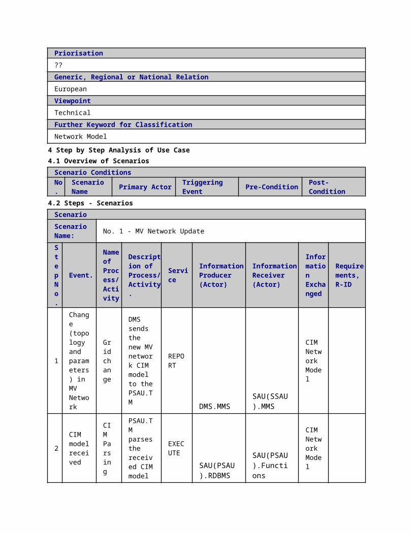
ed into MVDXP
ed into MVDXP
ed into MVDXP
6
MVDXP confirms the data update
Check flag
MVDXP confirms the data update
EXECUTE
SAU(PSAU).RDBMS
SAU(PSAU).Functions
MVDXP confirms the data update
7
MVPC asks for inputs
Data storage
MVPC asks for inputs
EXECUTE
SAU(PSAU).Functions
SAU(PSAU).RDBMS
MVPC asks for inputs
8
MVPC imports inputs from MVDXP
Data storage
MVPC imports inputs from MVDXP
EXECUTE
SAU(PSAU).RDBMS
SAU(PSAU).Functions
MVPC imports inputs from MVDXP
9
MVPC imports inputs from MVDXP
Data storage
MVPC imports inputs from MVDXP
EXECUTE
SAU(PSAU).RDBMS
SAU(PSAU).Functions
MVPC imports inputs from MVDXP
10
MVPC runs the OPF algorithm to calculate the optimum in MV network
Optimal power flow
MVPC runs the OPF algorithm to calculate the optimum in MV network
EXECUTE
SAU(PSAU).Functions
SAU(PSAU).Functions
MVPC runs the OPF algorithm to calculate the optimum in MV network
1 MVPC Data MVPC EXE SAU(PSAU). SAU(PSAU). MVPC

1
sends its outputs into MV database (MVDXP) storage
sends its outputs into MV database (MVDXP)
CUTE Functions RDBMS
sends its outputs into MV database (MVDXP)
12
MVIEDs confirmation regarding new settings
Reading/Writing IEDs setting
MVIEDs confirmation regarding new settings
EXECUTE
IED(PSIED).MMS
SAU(PSAU).MMS
Confirmation of new IED settings
13
MVIEDs confirmation regarding new settings
Data storage
MVIEDs confirmation regarding new settings
EXECUTE
SAU(PSAU).MMS
SAU(PSAU).RDBMS
Confirmation of new IED settings
ScenarioScenario Name: No. 2 - AS1: OPF does not converge
Step No.
Event.
Name of Process/ Activity
Description of Process/ Activity.
Service
Information Producer (Actor)
Information Receiver (Actor)
Information Exchanged
Requirements, R-ID
1 OPF calculation of step 9 in the normal sequence does not converg
Detect error, Control functions
OPF calculation of step 9 in the normal sequence does not converg
EXECUTE
SAU(PSAU).Functions
SAU(PSAU).Functions

e. Recovery methods are tried. These can include e.g. changing the optimization algorithm parameters such as the number of iteration rounds, type of limits etc.
e. Recovery methods are tried. These can include e.g. changing the optimization algorithm parameters such as the number of iteration rounds, type of limits etc.
2
OPF converges after recovery methods. Return to step 10 in the normal sequence.
Data storage
OPF converges after recovery methods. Return to step 10 in the normal sequence.
EXECUTE
SAU(PSAU).Functions
PSAU.DXP.RDBMS
Medium Voltage Power Control output
3 OPF does not converge after recovery methods and network state is acceptable. Write a
Data storage
OPF does not converge after recovery methods and network state is acceptable. Write a
EXECUTE
SAU(PSAU).Functions
PSAU.DXP.MMS
Log message

log message stating that OPF did not converge to the database.
log message stating that OPF did not converge to the database.
4
OPF does not converge after recovery methods and network state is unacceptable. Rule based algorithm is tried to restore the network to an acceptable state.
Control functions
OPF does not converge after recovery methods and network state is unacceptable. Rule based algorithm is tried to restore the network to an acceptable state.
EXECUTE
SAU(PSAU).Functions
SAU(PSAU).Functions
5 Rule based algorithm is able to restore the network to an acceptable state. Return to step 10 in normal sequence. Write a
Data storage
Rule based algorithm is able to restore the network to an acceptable state. Return to step 10 in normal sequence. Write a
EXECUTE
SAU(PSAU).Functions
SAU(PSAU).RDBMS
Medium Voltage Power Control output Log message
log message stating that OPF did not converge to the database.
log message stating that OPF did not converge to the database.
6
Rule based algorithm is unable to restore the network to an acceptable state. Send an alarm signal to the operator. Send a help request to upper level controller.
Data storage
Rule based algorithm is unable to restore the network to an acceptable state. Send an alarm signal to the operator. Send a help request to upper level controller.
EXECUTE
SAU(PSAU).Functions
SAU(PSAU).RDBMS
Help request Log message
7 Unacceptable network state remained longer than a predefined time. Write predetermined IED settings to the database (step 10 in
Data storage
Unacceptable network state remained longer than a predefined time. Write predetermined IED settings to the database (step 10 in
EXECUTE
SAU(PSAU).Functions
SAU(PSAU).RDBMS
Setting Values of IEDs
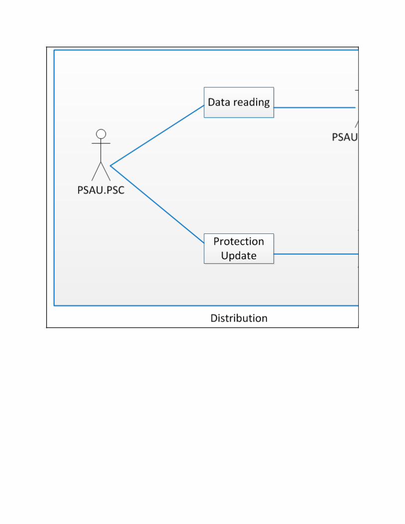
the normal sequence).
the normal sequence).
ScenarioScenario Name: No. 3 - AS2: Proper input data not available
Step No.
Event.
Name of Process/ Activity
Description of Process/ Activity.
Service
Information Producer (Actor)
Information Receiver (Actor)
Information Exchanged
Requirements, R-ID
1
Adequate input data is not available. Call a function that tries to solve the problem. Write an alarm message to the database.
Detect error
Adequate input data is not available. Call a function that tries to solve the problem. Write an alarm message to the database.
EXECUTE
SAU(PSAU).Functions
SAU(PSAU).RDBMS
Log message
2
Input data has been missing for a predefined time. Predetermined IED settings are written to the database.
Data storage
Input data has been missing for a predefined time. Predetermined IED settings are written to the database.
EXECUTE
SAU(PSAU).Functions
SAU(PSAU).RDBMS
Setting Values of IEDs
ScenarioScenario Name: No. 4 - AS3: Network in fault location, isolation or supply restoration state
Step
Event. Name of
Description of
Service
Information Producer
Information Receiver
Information
Requirements, R-ID

No.
Process/ Activity
Process/ Activity.
(Actor) (Actor) Exchanged
1
Network is in fault location, isolation or supply restoration state. PC algorithm is not executed.
Check flag
Network is in fault location, isolation or supply restoration state. PC algorithm is not executed.
EXECUTE
SAU(PSAU).RDBMS
SAU(PSAU).Functions
Flag
5 Information ExchangedInformation ExchangedName of Information (ID)
Description of Information Exchanged Requirements to information data
Setting Values of IEDs-Request
Setting Values of IEDs
State Estimation Results
line currents, node voltages, line power flow, estimated load and productions etc
Is data updated-Request
Is data updated-Reply
Data import request
Medium Voltage Power Control output
automatic voltage regulator set points of transformers, automatic reactive power set points of MV capacitor banks, MV DG units reference reactive power, MV DG unit curtailed power etc
Confirmation of new IED settings
Help request Help request from other controller
Log message Log message
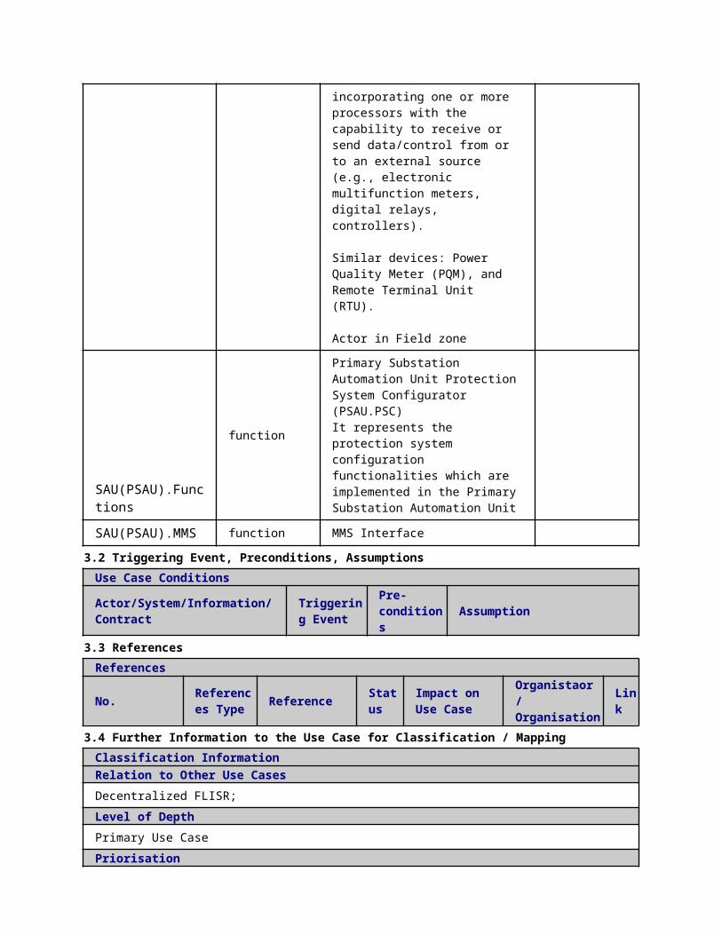
6 Requirements (optional)Requirements (optional)
7 Common Terms and DefinitionsCommon Terms and DefinitionsTerm Definition
8 Custom Information (optional)Custom Information (optional)Key Value Refers to Section
1 Description of the Use Case1.1 Name of the Use Case
Use Case Identification
IDArea / Domain(s)/Zone(s)
Name of the Use Case
239 Low Voltage Power Control (LVPC) Offline Cost Parameter Update
1.2 Version ManagementVersion ManagementFrom: Version 1.2.: Minor modifications based on Jasmin’s comments, 9.2.2015, Anna Kulmala
1.3 Scope and Objectives of Use CaseScope and Objectives of Use Case
ScopeThe LVPC in offline operation is part of a more general scheme called “Congestion Managementâ€. The LVPC (offline) tries to control and optimize� the power flow in future states of the LV network.
Objective(s)The objective of the offline LVPC is to utilize the low voltage state forecaster (LVSF) information to define the value of cost parameters and prevent extra control actions (e.g. to decrease the number of tap changer operations in the future states of the network).
Related businesscase(s)
1.4 Narrative of Use CaseNarrative of Use CaseShort descriptionThis use case demonstrates how the offline LVPC interacts with other actors in order to define the value of cost parameters and prevent extra control actions (e.g. to decrease the number of tap changer operations in the future states of the network).Complete descriptionThe main functionality of the offline LVPC is to define cost parameters to avoid extra actions. For instance, it prevents constant operation i.e. hunting of transformer tap changers by changing the cost parameters of the real-time LVPC.
For defining the cost parameters, the offline LVPC requires interacting with other actors. The actors directly interacting with offline LVPC (SSAU.PCPU application) are the following:
• Secondary Substation Automation Unit Data Exchange Platform (SSAU.DXP) where offline
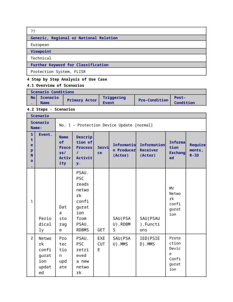
LVPC reads all necessary inputs and writes changes of OPF cost parameters.
The actors updating necessary data in the SSAU.DXP to be further used by offline LVPC are as following:
• Secondary Substation Automation Unit State Forecaster (SSAU.SF)• Control Centre Topology Manager (DMS.TM)
This use case presents the required interfaces for operation of the offline LVPC.
1.5 General RemarksGeneral Remarks
2 Diagrams of Use Case
3 Technical Details3.1 Actors
ActorsGrouping Group DescriptionActor Name Actor Type Actor Description Further
information specific to this
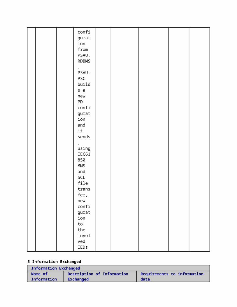
Use Case
SAU(SSAU).Functions
functionSecondary Substation Automation Unit Power Control Offline Cost Parameter Update
SAU(SSAU).RDBMS function Database SSAU
3.2 Triggering Event, Preconditions, AssumptionsUse Case ConditionsActor/System/Information/Contract
Triggering Event
Pre-conditions Assumption
3.3 ReferencesReferences
No. References Type Reference Statu
sImpact on Use Case
Organistaor / Organisation
Link
3.4 Further Information to the Use Case for Classification / MappingClassification InformationRelation to Other Use CasesLevel of DepthPriorisationHighGeneric, Regional or National RelationGenericViewpointTechincalFurther Keyword for ClassificationDistribution grid management...
4 Step by Step Analysis of Use Case4.1 Overview of Scenarios
Scenario ConditionsNo.
Scenario Name Primary Actor Triggering Event Pre-Condition Post-Condition
4.2 Steps - ScenariosScenarioScenario Name: No. 1 - PS1: Normal Sequence
Step No.
Event.
Name of Process/ Activity
Description of Process/ Activity.
Service
Information Producer (Actor)
Information Receiver (Actor)
Information Exchanged
Requirements, R-ID
1 SSAU.PCPU checks if data updated into
Check flag
Executed in parallel with step
REPORT
SAU(SSAU).Functions
SAU(SSAU).RDBMS
Is data updated-Request
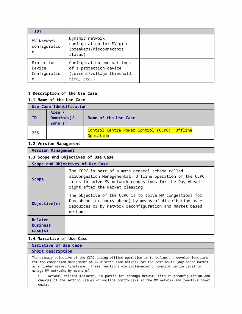
SSAU.DXP 81
2
SSAU.DXP confirms the data update
Check flag
Executed in parallel with step 81
REPORT
SAU(SSAU).RDBMS
SAU(SSAU).Functions
Is data updated-Reply
3
SSAU.PCPU asks for data import
Data storage
Executed in parallel with step 81
EXECUTE
SAU(SSAU).Functions
SAU(SSAU).RDBMS
Data import request
4
SSAU.PCPU imports inputs from SSAU.DXP
Data storage
Executed in parallel with step 81
REPORT
SAU(SSAU).RDBMS
SAU(SSAU).Functions
State forecasting result
5SSAU.PCPU runs the OPF algorithm to calculate the cost parameters.
Optimal power flow
Note: Depending on the time horizon used, the OPF will run several times to compute the cost parameters
EXECUTE
SAU(SSAU).Functions
SAU(SSAU).Functions
Cost Parameters
6 SSAU. Dat Note: REP SAU(SSAU).F SAU(SSAU).R Cost

PCPU sends its outputs into SSAU.DXP
a storage
Depending on the time horizon used, the OPF will run several times to compute the cost parameters ORT unctions DBMS
Parameters
ScenarioScenario Name: No. 2 - AS1: OPF does not converge
Step No.
Event.
Name of Process/ Activity
Description of Process/ Activity.
Service
Information Producer (Actor)
Information Receiver (Actor)
Information Exchanged
Requirements, R-ID
1 Step 5 of the normal sequence has been successfully completed and OPF calculation of step 6 does not converge. SSAU.PC
Detect error
Note: Depending on the time horizon used, the OPF will run several times to comp
EXECUTE
SAU(SSAU).Functions
SAU(SSAU).RDBMS
Log message
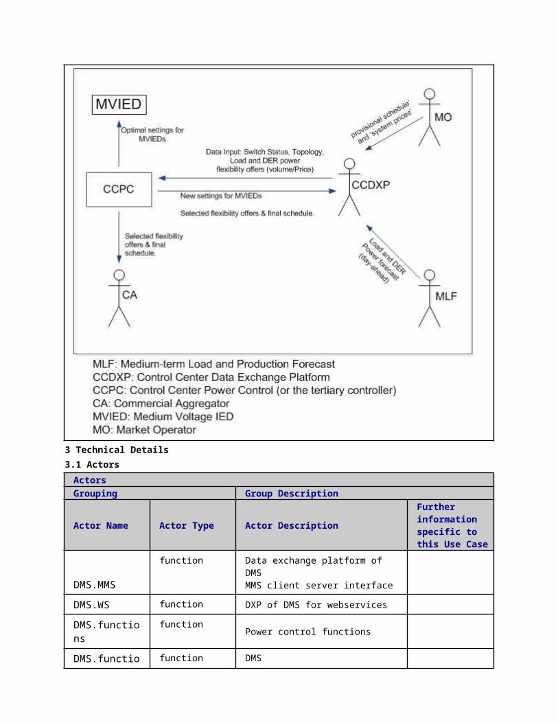
PU checks whether this happened also at the previous round
ute the cost parameters
2
OPF converged at the previous round. Stop SSAU.PCPU operation and wait for the next measurements to come in. Write a log message to the database.
Detect error
Note: Depending on the time horizon used, the OPF will run several times to compute the cost parameters
EXECUTE
SAU(SSAU).Functions
SAU(SSAU).RDBMS
Log message
3 OPF did not converge at the previous round.Write a log message to the database.
Detect error
Note: Depending on the time horizon used, the OPF will run several
EXECUTE
SAU(SSAU).Functions
SAU(SSAU).RDBMS
Log message
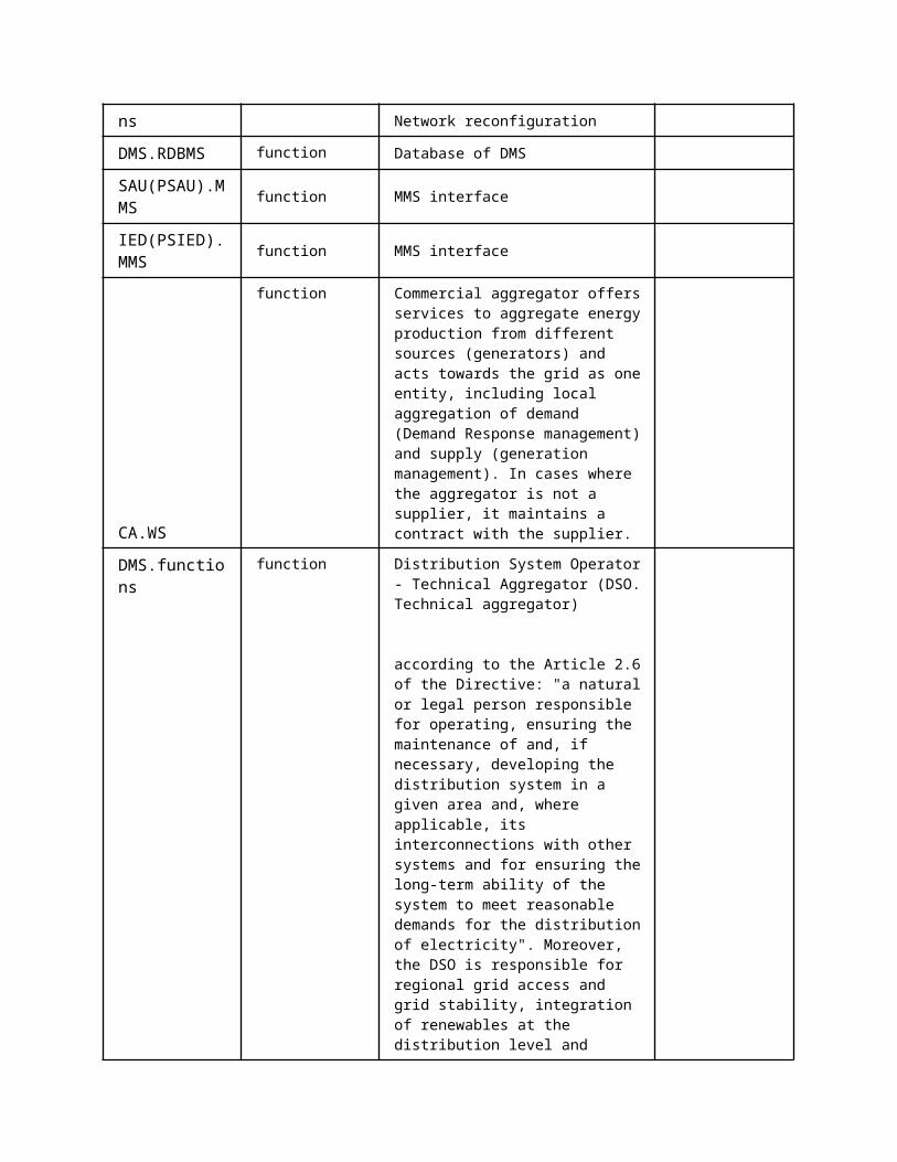
times to compute the cost parameters
4
Send predetermined cost parameters to the SSAU.DXP.
Data storage
Note: Depending on the time horizon used, the OPF will run several times to compute the cost parameters
EXECUTE
SAU(SSAU).Functions
SAU(SSAU).RDBMS
Predetermined cost parameters
ScenarioScenario Name: No. 3 - AS2: Proper input data is not available
Step No.
Event.
Name of Process/ Activity
Description of Process/ Activity.
Service
Information Producer (Actor)
Information Receiver (Actor)
Information Exchanged
Requirements, R-ID
1 SSAU.PCPU input data is not available or is not valid.SSAU.PCPU checks
Detect error
internal calculations
EXECUTE
SAU(SSAU).Functions
SAU(SSAU).Functions SAU(SSAU).RDBMS
Cost Parameters
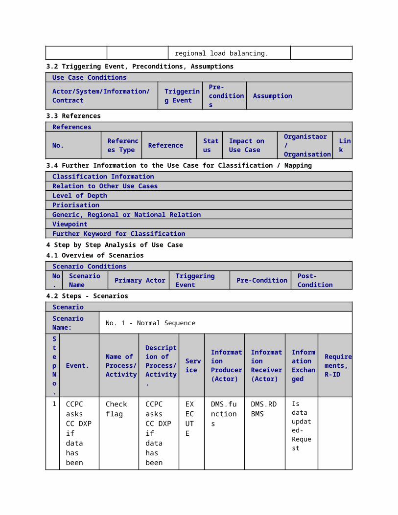
whether this happened also at the previous round
2
if SSAU.PCPU checks whether this happened also at the previous round.Stop SSAU.PCPU operation and wait for the next measurements to come in. Write a log message to the database.
Report error
REPORT
SAU(SSAU).Functions
SAU(SSAU).RDBMS
Log message
3
if SSAU.PCPU was not successful at the previous round. Write a log message to the database.
Report error
REPORT
SAU(SSAU).Functions
SAU(SSAU).RDBMS
Log message
4
Send predetermined cost parameters to the SSAU.DXP.
Data storage
EXECUTE
SAU(SSAU).Functions
SAU(SSAU).RDBMS
Predetermined cost parameters
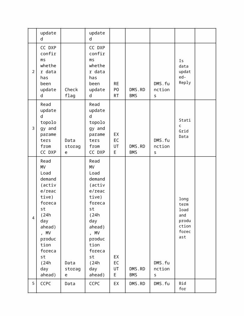
5 Information ExchangedInformation ExchangedName of Information (ID)
Description of Information Exchanged Requirements to information data
State forecasting result
line currents, node voltages, line power flow, estimated load and productions etc.
Is data updated-Request
Is data updated-Reply
Data import request
Cost Parameters
cost of operation of on-load tap changers (OLTCs) etc.cost of generation curtailmentcost of demand response
Log message Log message
Predetermined cost parameters
1 Description of the Use Case1.1 Name of the Use Case
Use Case Identification
IDArea / Domain(s)/Zone(s)
Name of the Use Case
143 Low Voltage Network Power Control (LVPC) in Real Time Operation
1.2 Version ManagementVersion ManagementFrom: Version 1.2 9.2.2015 Authors: Anna Kulmala and Farzad Azimzadeh Moghaddam (TUT)
Reviewers: Sami Repo and Jasmin Mehmedalic
1.3 Scope and Objectives of Use CaseScope and Objectives of Use Case
ScopeThe LVPC is part of a more general scheme called “Congestion Managementâ€. The LVPC tries to control and optimize the power flow in LV �network.
Objective(s) The objective of the LVPC is to utilize the low voltage state estimation (LVSE) information to control and optimize the power flow in LV network.
Related businesscase(s)
1.4 Narrative of Use CaseNarrative of Use CaseShort descriptionThis use case demonstrates how the LVPC interacts with other actors in order to optimize and control
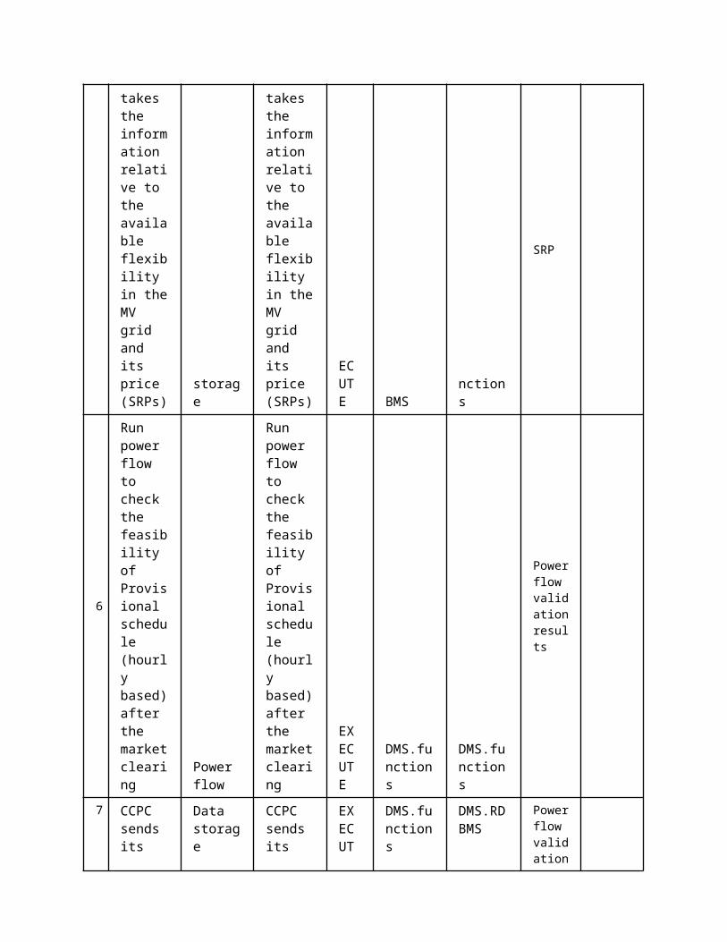
the power flow in LV network.Complete descriptionThe main functionality of the LVPC is to mitigate congestion in the LV networks. The LVPC tries to reach and balance the following goals:
Reduction of the LV network losses Reduction of production curtailment Minimizing the load control actions and tap changer operations Reducing the voltage violation at each node
In order to reach the above-mentioned goals, the LVPC requires interacting with other actors. The actors directly interacting with LVPC (SSAU.PC application) are the following:
Secondary Substation Automation Unit Data Exchange Platform (SSAU.DXP) where LVPC reads all necessary inputs and writes changes of IED settings.
The actors updating necessary data in the SSAU.DXP to be further used by LVPC are as follows: Control Centre Topology Manager (DMS.TM) Primary Substation Unit Block OLTC’s of Transformers (PSAU.BOT) Secondary Substation Automation Unit Power Control Offline Cost Parameter Update (SSAU.PCPU) Secondary Substation Automation Unit State Estimation (SSAU.SE) and complete low voltage network real-time monitoring use
case providing necessary data to SSAU.SE Intelligent electronic devices (IEDs) located in the LV network where measurement data is received and control commands are
sent
This use case presents the required interfaces for operation of the LVPC.
1.5 General RemarksGeneral Remarks
Issue - here specific ones
Impact of Issue on Use Case Reference – law, standard, others
Customer-owned distributed generations (DGs) metering information
Measurements from customer-owned DG units is required as input of the LVPC.
Information of customer’s controllable loads
This is required as input of the LVPC.
2 Diagrams of Use Case
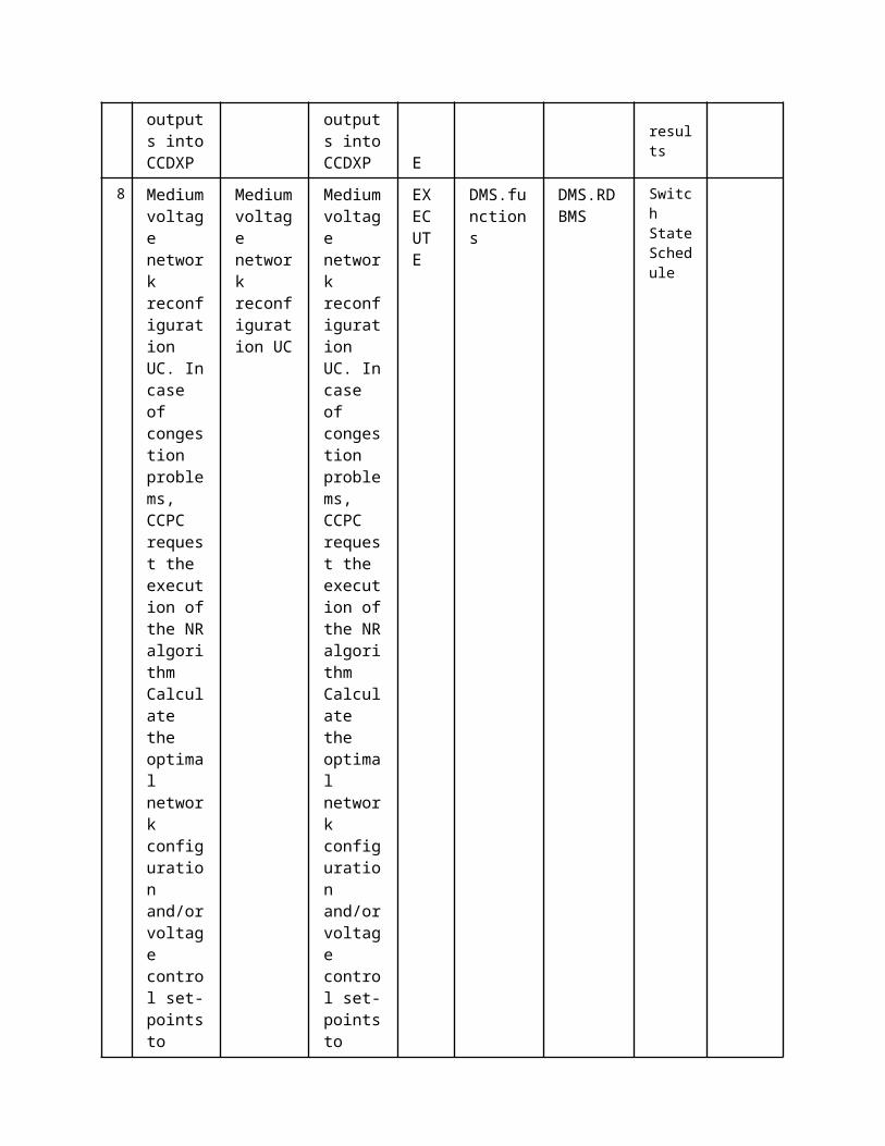
3 Technical Details3.1 Actors
ActorsGrouping Group Description
Actor Name Actor Type Actor DescriptionFurther information specific to this Use Case
SAU(SSAU).MMS function MMS interface of SSAU
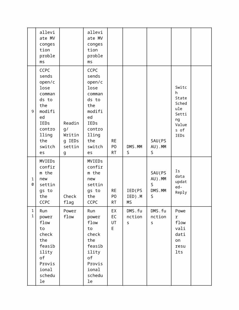
SAU(SSAU).RDBMS function Database of SSAU
IED(SSIED).MMS function MMS interface of secondary substation IED
SAU(SSAU).Functions
function SSAU Power Control
3.2 Triggering Event, Preconditions, AssumptionsUse Case ConditionsActor/System/Information/Contract
Triggering Event
Pre-conditions Assumption
3.3 ReferencesReferences
No. References Type Reference Statu
sImpact on Use Case
Organistaor / Organisation
Link
3.4 Further Information to the Use Case for Classification / MappingClassification InformationRelation to Other Use CasesLevel of DepthPriorisationHighGeneric, Regional or National RelationGenericViewpointTechnicalFurther Keyword for ClassificationDistribution grid management...
4 Step by Step Analysis of Use Case4.1 Overview of Scenarios
Scenario ConditionsNo.
Scenario Name Primary Actor Triggering Event Pre-Condition Post-Condition
4.2 Steps - ScenariosScenarioScenario Name: No. 1 - Normal Sequence
Step No.
Event.Name of Process/ Activity
Description of Process/ Activity.
Service
Information Producer (Actor)
Information Receiver (Actor)
Information Exchanged
Requirements, R-ID
1
SSAU requests settings of LVIEDs
Reading/Writing IEDs setting
SSAU requests settings of LVIEDs
REPORT
SAU(SSAU).MMS
IED(SSIED).MMS
Setting Values of IEDs-Request

2
LVIEDs send value of their settings to SAU
Reading/Writing IEDs setting
LVIEDs send value of their settings to SAU
REPORT
IED(SSIED).MMS
SAU(SSAU).MMS
Setting Values of IEDs
3
SSAU inserts the LVIED settings into LV database (LVDXP)
Data storage
SSAU inserts the LVIED settings into LV database (LVDXP)
EXECUTE
SAU(SSAU).MMS
SAU(SSAU).RDBMS
Setting Values of IEDs
4
LVPC asks LVDXP if new data have been updated into LVDXP
Check flag
LVPC asks LVDXP if new data have been updated into LVDXP
EXECUTE
SAU(SSAU).Functions
SAU(SSAU).RDBMS
Is data updated-Request
5
LVDXP confirms the data update
Check flag
LVDXP confirms the data update
EXECUTE
SAU(SSAU).RDBMS
SAU(SSAU).Functions
Is data updated-Reply
6
LVPC ask for data import
Data storage
LVPC ask for data import
EXECUTE
SAU(SSAU).Functions
SAU(SSAU).RDBMS
Data import request
7 LVPC imports inputs
Data storage
LVPC imports inputs
EXECUTE
SAU(SSAU).RDBMS
SAU(SSAU).Functions
Setting Values of
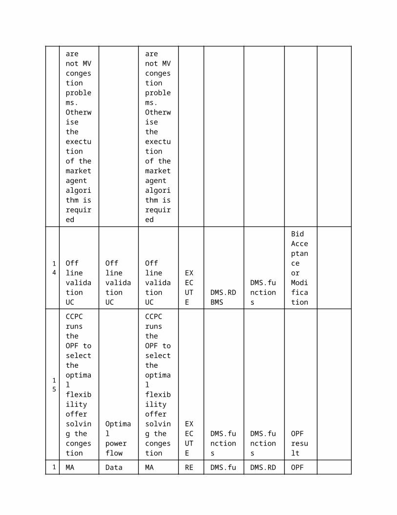
from LVDXP
from LVDXP
IEDs State Estimation Results
8
LVPC runs the OPF algorithm to calculate the optimum in LV network
Optimal power flow
LVPC runs the OPF algorithm to calculate the optimum in LV network
EXECUTE
SAU(SSAU).Functions
SAU(SSAU).Functions
Low Voltage Power Control outputs
9
LVPC sends its outputs into LV database (LVDXP)
Data storage
LVPC sends its outputs into LV database (LVDXP)
EXECUTE
SAU(SSAU).Functions
SAU(SSAU).RDBMS
Low Voltage Power Control outputs
10
In the case of new settings for LVIEDS
Reading/Writing IEDs setting
In the case of new settings for LVIEDS
REPORT
SAU(SSAU).MMS
IED(SSIED).MMS
Setting Values of IEDs
11
LVIEDs confirmation regarding new settings
Check flag
LVIEDs confirmation regarding new settings
REPORT
IED(SSIED).MMS
SAU(SSAU).MMS
Confirmation of new IED settings
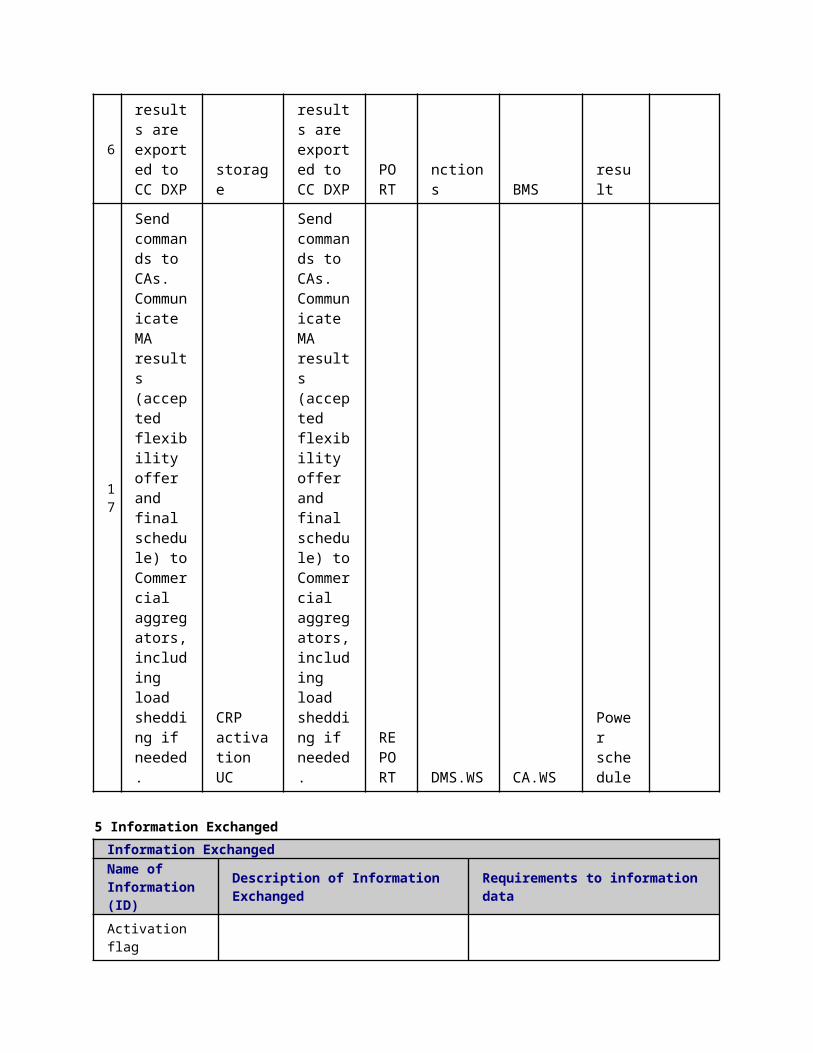
ScenarioScenario Name: No. 2 - AS1: OPF does not converge
Step No.
Event.
Name of Process/ Activity
Description of Process/ Activity.
Service
Information Producer (Actor)
Information Receiver (Actor)
Information Exchanged
Requirements, R-ID
1
OPF calculation of step 9 in the normal sequence does not converge. Recovery methods are tried. These can include e.g. changing the optimization algorithm parameters such as the number of iteration rounds, type of limits etc.
Detect error
EXECUTE
SAU(SSAU).Functions
SAU(SSAU).Functions
2 OPF converges after recovery methods. Return to step 10 in the
Data storage
EXECUTE
SAU(SSAU).Functions
SAU(SSAU).RDBMS
Low Voltage Power Control outpu

normal sequence.
ts
3
OPF does not converge after recovery methods and network state is acceptable. Write a log message stating that OPF did not converge to the database.
Data storage
EXECUTE
SAU(SSAU).Functions
SAU(SSAU).Functions
Log message
4
OPF does not converge after recovery methods and network state is unacceptable. Rule based algorithm is tried to restore the network to an acceptable state.
Control functions
EXECUTE
SAU(SSAU).Functions
SAU(SSAU).Functions
Log message
5 Rule based algorithm is able to restore the
Data storage
EXECUTE
SAU(SSAU).Functions
SAU(SSAU).RDBMS
Low Voltage Power Control

network to an acceptable state. Return to step 10 in normal sequence. Write a log message stating that OPF did not converge to the database.
outputs Log message
6
Rule based algorithm is unable to restore the network to an acceptable state. Send an alarm signal to the operator. Send a help request to upped level controller.
Data storage
EXECUTE
SAU(SSAU).Functions
SAU(SSAU).RDBMS
Help request Log message
7 Unacceptable network state remained longer than a predefin
Data storage
EXECUTE
SAU(SSAU).Functions
SAU(SSAU).RDBMS
Setting Values of IEDs
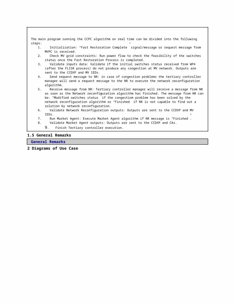
ed time. Write predetermined IED settings to the database (step 10 in the normal sequence).
ScenarioScenario Name: No. 3 - AS2: Proper input data not available
Step No.
Event.
Name of Process/ Activity
Description of Process/ Activity.
Service
Information Producer (Actor)
Information Receiver (Actor)
Information Exchanged
Requirements, R-ID
1
Adequate input data is not available. Call a function that tries to solve the problem. Write an alarm message to the database.
Detect error
EXECUTE
SAU(SSAU).Functions
SAU(SSAU).RDBMS
Log message
2 Input data has been missing for a predefined time. Predetermined IED settings are written
Data storage
EXECUTE
SAU(SSAU).Functions
SAU(SSAU).RDBMS
Setting Values of IEDs
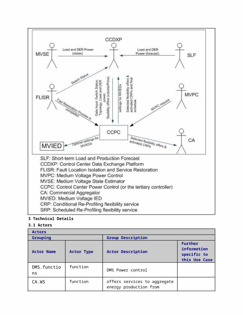
to the database.
ScenarioScenario Name: No. 4 - AS3: Network in fault location, isolation or supply restoration state
Step No.
Event.
Name of Process/ Activity
Description of Process/ Activity.
Service
Information Producer (Actor)
Information Receiver (Actor)
Information Exchanged
Requirements, R-ID
1
Network is in fault location, isolation or supply restoration state. PC algorithm is not executed.
Check flags
EXECUTE
SAU(SSAU).RDBMS
SAU(SSAU).Functions
Flag
5 Information ExchangedInformation ExchangedName of Information (ID)
Description of Information Exchanged Requirements to information data
Confirmation of new IED settings
Setting Values of IEDs
Setting Values of IEDs-Request
State Estimation Results
line currents, node voltages, line power flow, estimated load and productions etc
Is data updated-Request
Is data updated-
Reply
Data import request
Low Voltage Power Control outputs
automatic voltage regulator set points of transformers, automatic reactive power set points of LV capacitor banks, LV DG units reference reactive power, LV DG unit curtailed power etc.
Help request Help request from other controller
Log message Log message
1 Description of the Use Case1.1 Name of the Use Case
Use Case Identification
IDArea / Domain(s)/Zone(s)
Name of the Use Case
240 Block OLTC's of Transformers (BOT)
1.2 Version ManagementVersion ManagementFrom Version 1.2, 10.2.2015, Author: Farzad Azimzadeh Moghaddam (TUT) Comments by: Sami Repo, Anna Kulmala, Jasmin Mehmedalic
1.3 Scope and Objectives of Use CaseScope and Objectives of Use Case
Scope
The BOT unit is an input provider for medium voltage power control (MVPC) and low voltage power control (LVPC) and also the automatic voltage control relays controlling tap changers of HV/MV and MV/LV transformers. It sends block and unblock signal to MVPC, LVPC, MVIEDs and LVIEDs. Block signal prevents operation of OLTCs. Note: Intelligent Electronic devices (IEDs) in this document are Automatic Voltage Controllers of HV/MV and MV/LV transformers.
Objective(s)The objective of the BOT unit is to utilize state estimation (SE) information from both MV and LV networks. Using this information Bot is able to prevent unnecessary tap action of the OLTCs by sending block signals.
Related businesscase(s)
1.4 Narrative of Use CaseNarrative of Use CaseShort descriptionThis use case demonstrates how the BOT unit interacts with other units in order to generate its outputs. The main purpose is to show how different actors interact with each other.Complete descriptionThe main functionality of the BOT unit is to send block signals (along with block validity times) and unblock signals to LVPC and MVPC units and also their respective IEDs. Block and unblock signals are for the following reasons:• Solve the voltage disturbance problem as local as possible• Prevent hunting phenomenon of OLTCs operating in different voltage layers
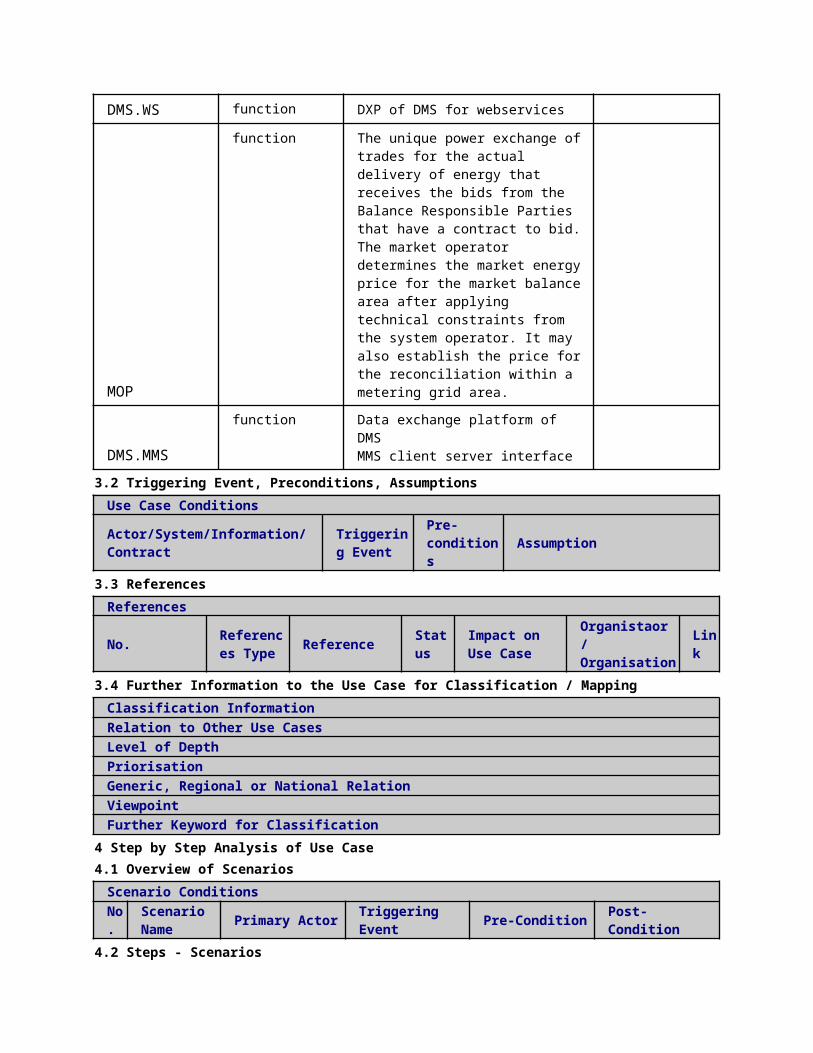
In order to reach the above-mentioned goals, the following actors are required:• PSAU Block OLTC’s of Transformers (PSAU.BOT)• PSAU Data Exchange Platform (PSAU.DXP)• PSAU Power Control (PSAU.PC)• Automatic Voltage Controller of Primary Substation (PSAU.IED.AVC)• SSAU Data Exchange Platform (SSAU.DXP)• SSAU Power Control (SSAU.PC)• Automatic Voltage Controller of Secondary Substation (SSAU.IED.AVC)
Note: - PSAU stands for Primary Substation Automation Unit- SSAU stands for Secondary Substation Automation Unit
State estimation data from MVSE and LVSE and network topology data from Topology Manager (TM) are required as inputs. This data is transferred to the BOT unit through MV and LV databases. Therefore, the following actors are also indirectly involved in the process of generating the BOT outputs:• PSAU State Estimation (PSAU.SE)• SSAU State Estimation (SSAU.SE)• DMS.TM
This use case presents the required interfaces for operation of the BOT unit.
1.5 General RemarksGeneral Remarks
2 Diagrams of Use Case
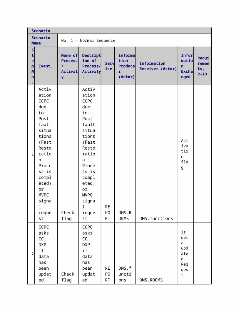
3 Technical Details3.1 Actors
ActorsGrouping Group DescriptionActor Name Actor Type Actor Description Further
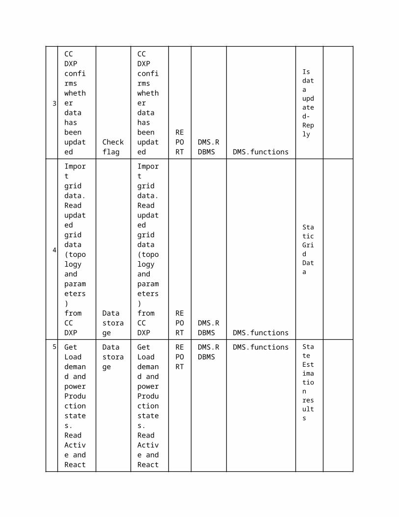
information specific to this Use Case
SAU(PSAU).MMS function MMS interface
SAU(PSAU).RDBMS function PSAU Data Exchange Platform
IED(PSIED-AVC-CTRL).MMS
function Automatic Voltage Controller of Primary Substation
SAU(SSAU).MMS function MMS interfaces
SAU(PSAU).Functions
function PSAU Power Control
SAU(PSAU).Functions
function PSAU Block OLTC’s of Transformers
IED(SSIED-AVC-CTRL).MMS
function Automatic Voltage Controller of Secondary Substation
3.2 Triggering Event, Preconditions, AssumptionsUse Case ConditionsActor/System/Information/Contract
Triggering Event
Pre-conditions Assumption
3.3 ReferencesReferences
No. References Type Reference Statu
sImpact on Use Case
Organistaor / Organisation
Link
3.4 Further Information to the Use Case for Classification / MappingClassification InformationRelation to Other Use CasesLevel of DepthPriorisationHighGeneric, Regional or National RelationGenericViewpointTechnicalFurther Keyword for ClassificationDistribution grid management...
4 Step by Step Analysis of Use Case4.1 Overview of Scenarios
Scenario ConditionsNo.
Scenario Name Primary Actor Triggering Event Pre-Condition Post-Condition
4.2 Steps - ScenariosScenarioScenario Name: No. 1 - Normal sequence
St Event Name of Descri Servic Information Information Informa Require
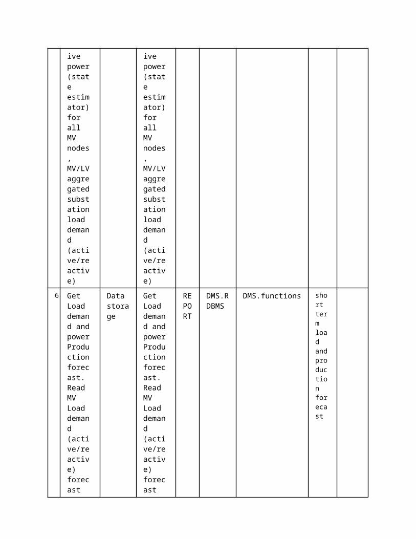
ep No.
. Process/ Activity
ption of Process/ Activity.
e Producer (Actor)
Receiver (Actor)
tion Exchanged
ments, R-ID
1
LVDXP inserts its outputs (OLTC state) into MVDXP
Data report
REPORT
SAU(SSAU).MMS
SAU(PSAU).MMS
State forecasting result
State Estimation results
2
BOT sends input request to MVDXP. BOT unit asks its required inputs from MVDXP
Data storage
REPORT
SAU(PSAU).Functions
SAU(PSAU).RDBMS
Data import request
3 BOT data imp
Data storage
EXECUTE
SAU(PSAU).RDBMS
SAU(PSAU).Functions
State forecasting result
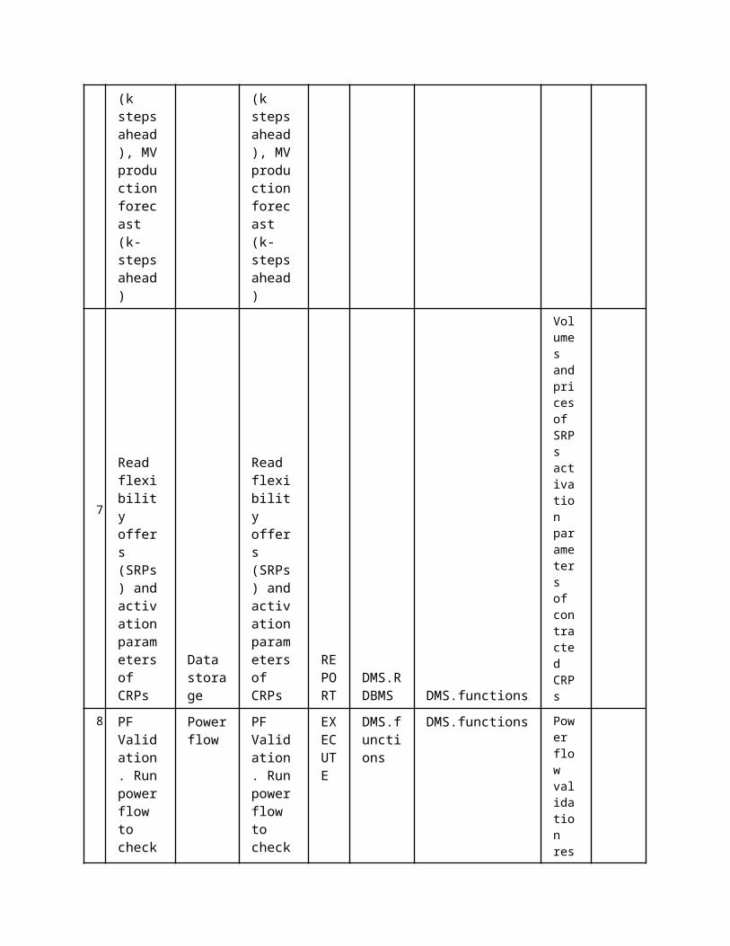
ort. BOT receives its inputs from MVDXP
State Estimation results
5
BOT sends its outputs to MVDXP
Data storage
EXECUTE
SAU(PSAU).Functions
SAU(PSAU).RDBMS
OLTC block and unblock signals
6
BOT sends its outputs to LVDXP via MVDXP
Data report
REPORT
SAU(PSAU).MMS
SAU(SSAU).MMS
OLTC block and unblock signals
7
BOT sends new settings to MVIEDS
Reading/Writing IEDs setting
Executed in parallel with step 5
REPORT
SAU(PSAU).MMS
IED(PSIED-AVC-CTRL).MMS
OLTC block and unblock signals
8 BOT sends new setti
Data report
Executed in parallel
REPORT
SAU(PSAU).MMS
SAU(SSAU).MMSIED(SSIED-AVC-CTRL).MMS
OLTC block and unblock signal

ngs to LVIEDs
with step 6
s
ScenarioScenario Name: No. 2 - AS 1: No input data for BOT
Step No.
Event.
Name of Process/ Activity
Description of Process/ Activity.
Service
Information Producer (Actor)
Information Receiver (Actor)
Information Exchanged
Requirements, R-ID
1
The PSAU.BOT has not received input data
Missing data
Executed in parallel with step 8
REPORT
SAU(PSAU).Functions
SAU(PSAU).RDBMS
Error signal generated by PSAU.BOT
ScenarioScenario Name: No. 3 - AS 2: BOT is not able to provide its outputs
Step No.
Event.
Name of Process/ Activity
Description of Process/ Activity.
Service
Information Producer (Actor)
Information Receiver (Actor)
Information Exchanged
Requirements, R-ID
1 The PSAU.BOT has not generated its outputs.If for any reason PSAU.BOT has not generated its
Check flag
Executed in parallel with step 8
REPORT
SAU(PSAU).Functions
SAU(PSAU).RDBMS
OLTC block and unblock signals

outputs, no block signal will be send i.e. all transformers are free to operate
5 Information ExchangedInformation ExchangedName of Information (ID)
Description of Information Exchanged Requirements to information data
Data import request
OLTC block and unblock signals
including the validity time of block signals
Error signal generated by PSAU.BOT
State forecasting result
node voltages, line currents, aggregated production etc.
State Estimation results node voltages, line currents etc.
1 Description of the Use Case1.1 Name of the Use Case
Use Case Identification
IDArea / Domain(s)/Zone(s)
Name of the Use Case
146 Power Quality Control
1.2 Version ManagementVersion Management
1.3 Scope and Objectives of Use CaseScope and Objectives of Use Case
ScopeThe aim is to propose methods to improve power quality in LV/MV networks with high penetration of power electronic-based generating units and/or other equipments.
Objective(s) The particular objectives of the UC are devoted to the design of the control algorithm for the proposed device --which is based on short-term storage

systems-- for flicker filtering in LV/MV grids. The proposed concepts are to be validated using lab-scale equipments.
Related businesscase(s)
1.4 Narrative of Use CaseNarrative of Use CaseShort descriptionWith the aim of power quality improvement, the UC explores the use of fast energy storage systems with high ramp power rates and short time responses, to rapidly exchange active and reactive power, thus smoothing power flows in LV networks and improving quality of current and voltage waveforms.Complete descriptionStorage systems will act as active filters connected at certain point of LV/MV networks. The storage system will be the tool for an ancillary service provider for the distribution network to perform such active filtering of flicker emission in the network.The steps are described below:1. Data with high resolution time from power quality meter and, with low resolution time from state estimation, are extracted by PSAU and SSAU at the local DXPs, through the function DS.2. Power quality indexes are calculated and compared with the threshold indicated by power quality standards (e.g. EN 50160), through the function Check Status of Electrical Variables (CSEV).3. In case some indexes are not satisfying control functions are run in order to obtain some effective control actions, through the function Control Functions (CFs).4. Control actions are sent to IEDs and to local DPXs through the function Compute Control Signals (SCSs).5. Control actions are stored by SSDXP and PSDXP with the function DS.
1.5 General RemarksGeneral Remarks
2 Diagrams of Use Case

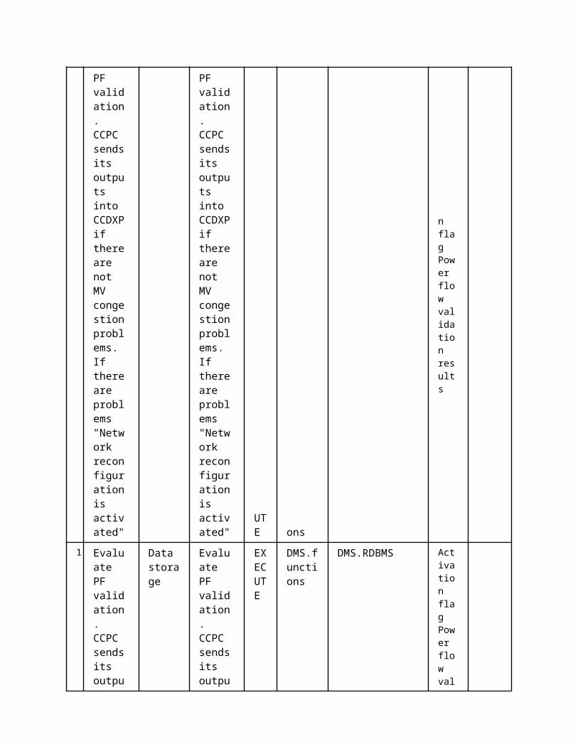
3 Technical Details3.1 Actors
ActorsGrouping Group Description
Actor Name Actor Type Actor DescriptionFurther information specific to this Use Case
IED(DIED).MMS function Distributed IED MMS interface
SAU(PSAU).Functions
function Primary Substation Automation Unit (PSAU)
SAU(PSAU).MMS function MMS interface for PSAU
SAU(PSAU).RDBMS function Database for PSAU
3.2 Triggering Event, Preconditions, AssumptionsUse Case ConditionsActor/System/Information/Contract
Triggering Event
Pre-conditions Assumption
3.3 ReferencesReferences
No. References Type Reference Statu
sImpact on Use Case
Organistaor / Organisation
Link
3.4 Further Information to the Use Case for Classification / MappingClassification InformationRelation to Other Use CasesLevel of DepthPriorisationGeneric, Regional or National RelationViewpointFurther Keyword for Classification
4 Step by Step Analysis of Use Case4.1 Overview of Scenarios
Scenario ConditionsNo.
Scenario Name Primary Actor Triggering Event Pre-Condition Post-Condition
4.2 Steps - ScenariosScenarioScenario Name: No. 1 - Flicker Reduction (similar scenarios for the other power quality problems)
Step No.
Event.Name of Process/ Activity
Description of Process/ Activity.
Service
Information Producer (Actor)
Information Receiver (Actor)
Information Exchanged
Requirements, R-ID
1 Normal opera
Data storage
Data with high
REPORT
SAU(PSAU).RDBMS
SAU(PSAU).Functions
Power quality

ting conditions of the grid
resolution time from power quality meter and, with low resolution time from state estimation, are extracted by PSAU and SSAU at the local DXPs, through the function DS
metrics
2 Data received by PSAU
power quality indexes
Power quality indexes are calculated and compared with the thres
EXECUTE
SAU(PSAU).Functions
SAU(PSAU).Functions
Threshold levels for power quality metrics
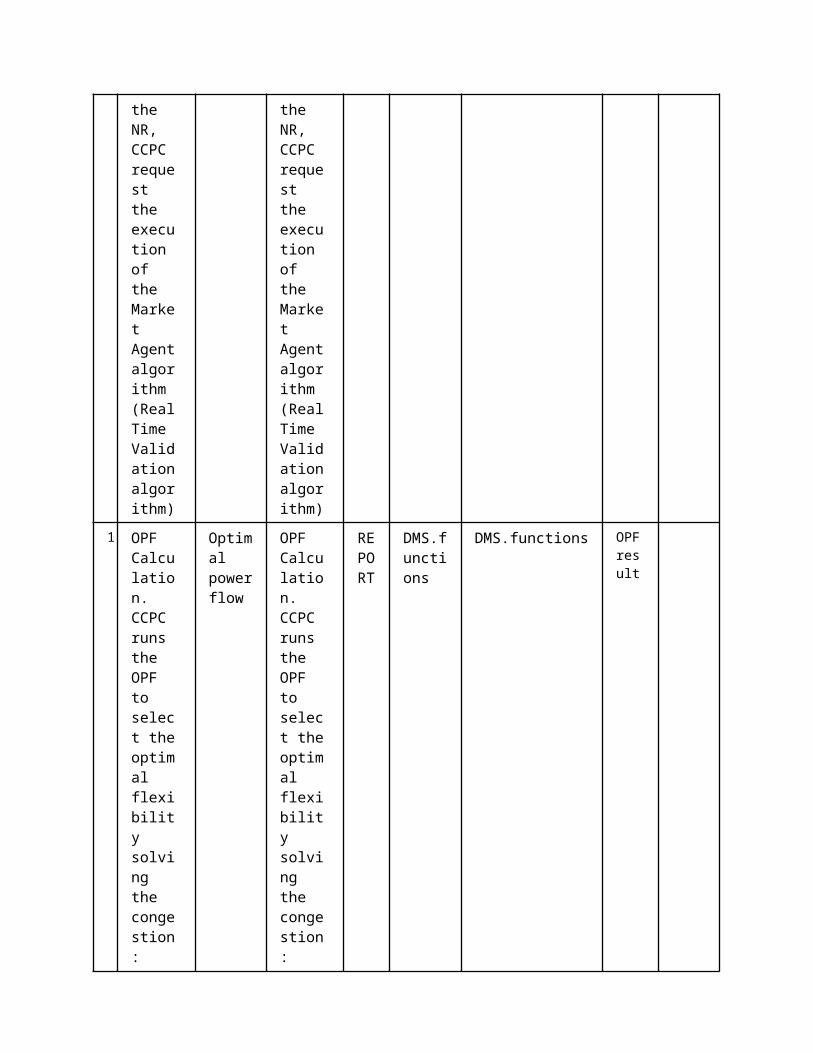
hold indicated by power quality standards (e.g. EN 50160), through the function CSEV
5 Power quality indexes evaluated
power quality control
In case some indexes are not satisfying control functions are run in order to obtain some effective control actions, through the
EXECUTE
SAU(PSAU).Functions
SAU(PSAU).Functions
Package sending ON/OFF signal for function CF to other functions
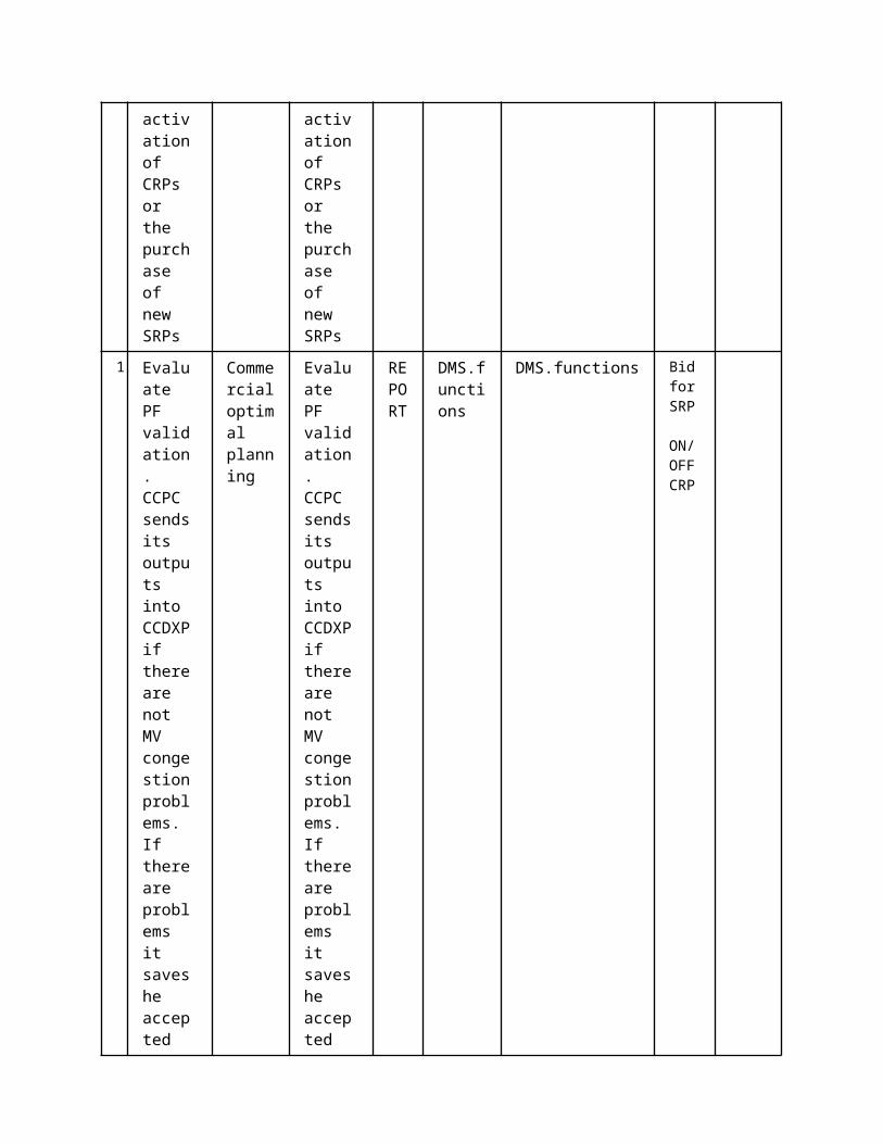
function CF
3
Decision on control actions determined and sent to DIEDs
Reading/Writing IEDs setting
Control actions are sent to DIEDs and to local DPXs through the function SCSs
EXECUTE
SAU(PSAU).MMS
IED(DIED).MMS
ON/OFF signal for function CF
4Control action performed by DIEDs
Data storage
Control actions are stored by SSDXP and PSDXP with the function DS
EXECUTE
SAU(PSAU).Functions
SAU(PSAU).RDBMS
Control actions performed by IEDs
5 Information ExchangedInformation ExchangedName of Information (ID)
Description of Information Exchanged Requirements to information data
Power quality metrics
Data with high resolution time from power quality meter
Threshold levels for power quality metrics
Comparison between power quality measurements and threshold levels through the function CSEV.
ON/OFF signal for function CF
In case some indexes are not satisfying control functions are run in

order to obtain some effectivecontrol actions, through the function CF.
Package sending ON/OFF signal for function CF to other functions
Control actions are sent to IEDs and to local DPXs through the function SCSs
Control actions performed by IEDs
Control actions are stored by SSDXP and PSDXP with the function DS
1 Description of the Use Case1.1 Name of the Use Case
Use Case Identification
IDArea / Domain(s)/Zone(s)
Name of the Use Case
233 Commercial aggregator asset planning
1.2 Version ManagementVersion Management
1.3 Scope and Objectives of Use CaseScope and Objectives of Use CaseScope Distribution network operation and interaction with aggregator.
Objective(s) Design and simulate the optimal participation of customers in electricity market, considering the grid constraints.
Related businesscase(s)
1.4 Narrative of Use CaseNarrative of Use CaseShort descriptionThis UC describes the operation of the commercial aggregator in order to evaluate the capacity of the DERs within its load area to perform scheduled Re-profiling (SRP) and conditional Re-profiling (CRP) actions (later described), then to match this availability with the requirements of the TSOs and technical aggregator contained in the flexibility tables and finally to send the bids of SRPs and CRPs to the market.Complete descriptionSRP is the offer of one or more DERs to produce an assigned power during an assigned period of time, meanwhile CRP is the offer of one or more DERs to be ready and available to change the output power in a certain range for an assigned period of time. The commercial aggregator cannot access to the property information of the DSO, for security reasons, namely the need for reservation of key information as the weaknesses of the grid. However, it receives from the technical aggregator the flexibility tables that represent the scope within the commercial aggregator can bid for. Furthermore, in the view of developing a concept closer to a free market, the commercial aggregator can access the information of the HEMS within its load area and can use forecast services, weather forecast agencies reports, and in general, information from external providers in order to optimize the schedules of the DERs belonging to its load area. The designed process consists in the following
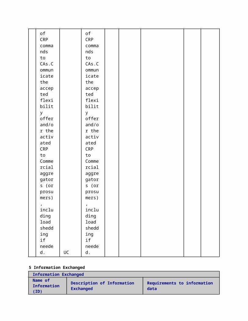
steps:1. Information about the customers of the Commercial Aggregator (CA) is retrieved periodically, with the function Flexibility and DER Status Acquisition (FDA) from the HEMSs and stored in the Commercial aggregator Data eXchange Platform (CADXP) with the function DS. The same is done for forecasts for the production of the DERs and the demand obtained from external entities.2. The flexibility tables, sent by the technical aggregator, are retrieved by the Commercial Aggregator (CA) with the function data storage from the Commercial aggregator Data eXchange Platform (CADXP), with the function data storage (DS).3. The commercial aggregator, taken into consideration the data from the customer, the forecast and the flexibility tables, calculates the optimal scheduling for the resources and customers that it manages, with the function Compute Schedule (CS).4. The commercial aggregator submits a bid to the Market Operator (MO), with the function Bid Submission (BS).
1.5 General RemarksGeneral Remarks
2 Diagrams of Use Case
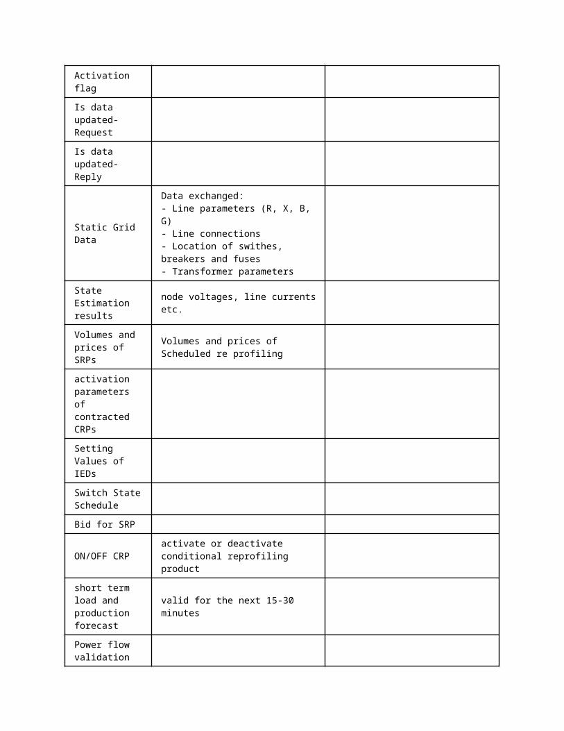

3 Technical Details3.1 Actors
ActorsGrouping Group Description
Actor Name Actor Type Actor DescriptionFurther information specific to this Use Case
CA.RDBMS function Commercial aggregator Data eXchange Platform (CADXP)
CA.functions
function Statistical calculations performed by the Commerical aggregator in order to obtain key information for SRP and CRP trading and otpimal energy procurement
CA.WSfunction web services interface of commercial
aggregator
MOP function Market Operator Platform
SPP
function Wheater data provider
Energy prices for the next day and intraday.Forecast of DERs and demand for the area of the CA for next day and intraday.Chariging hours vehicle
IED(HEMS).WS
function Home energy managment systemDistributed Energy Resource (Distributed Generation, Demand Response and Storage) interface
3.2 Triggering Event, Preconditions, AssumptionsUse Case ConditionsActor/System/Information/Contract
Triggering Event
Pre-conditions Assumption
3.3 ReferencesReferences
No. References Type Reference Statu
sImpact on Use Case
Organistaor / Organisation
Link
3.4 Further Information to the Use Case for Classification / MappingClassification InformationRelation to Other Use CasesLevel of DepthPriorisationGeneric, Regional or National RelationViewpointFurther Keyword for Classification
4 Step by Step Analysis of Use Case4.1 Overview of Scenarios
Scenario Conditions

No.
Scenario Name Primary Actor Triggering Event Pre-Condition Post-Condition
4.2 Steps - ScenariosScenarioScenario Name: No. 1 - Relevant information for commercial aggregator energy procurement
Step No.
Event.
Name of Process/ Activity
Description of Process/ Activity.
Service
Information Producer (Actor)
Information Receiver (Actor)
Information ExchangedRequirements, R-ID
1
Aggergator receives the relevant information to prepare the bids
Data storage
Executed in parallel with step 81
REPORT SPP CA.WS
Demand dataDER and switch schedulesMeteorological Forcast
2
Aggregator extract historical load and demand information from its database
Data storage
Executed in parallel with step 81
REPORT
CA.RDBMS
CA.functions
long term load and production forecastshort term load and production forecast
3 Aggregator matches service
Data storage
Executed in parallel with
EXECUTE
CA.functions
CA.RDBMS
Control function result

provider and its own information and store them in database
step 81
ScenarioScenario Name: No. 2 - Bid preparation
Step No.
Event.Name of Process/ Activity
Description of Process/ Activity.
Service
Information Producer (Actor)
Information Receiver (Actor)
Information Exchanged
Requirements, R-ID
1
Extract key information for bid preparation from database
Data storage
Executed in parallel with step 81
EXECUTE
CA.RDBMS
CA.functions
Control function result
2
The aggregator prepare the bids to be submitted to the market operator
Commercial optimal planning
Executed in parallel with step 81
EXECUTE
CA.functions
CA.RDBMS
SRP bid
3
The aggregator submits the bid to the market operator
Bid submission
Executed in parallel with step 81
REPORT CA.WS MOP
SRP bid

4
The market operator matches the bid by means of a dedicated algorithm/software
Market clearance
Executed in parallel with step 81
EXECUTE MOP MOP
SRP bid
5
The market opeartor realize the validation of the technical constraints (asking to DSO and TSO)
Off line validation UCReal time validation UC
Executed in parallel with step 81
EXECUTE MOP CA.WS
Validation Results
6 The aggregator prepare the power schedules
Commercial optimal planning
Executed in parallel with step 81
EXECUTE
CA.functions
CA.RDBMS
Energy plan
7
Commercial aggregator reorganize and forward the poewr schedules to the prosumers
Reading/Writing IEDs setting
Executed in parallel with step 81
REPORT CA.WS
IED(HEMS).WS
Energy plan
5 Information ExchangedInformation ExchangedName of Information (ID)
Description of Information Exchanged Requirements to information data
6 Requirements (optional)Requirements (optional)
7 Common Terms and DefinitionsCommon Terms and DefinitionsTerm Definition
8 Custom Information (optional)Custom Information (optional)
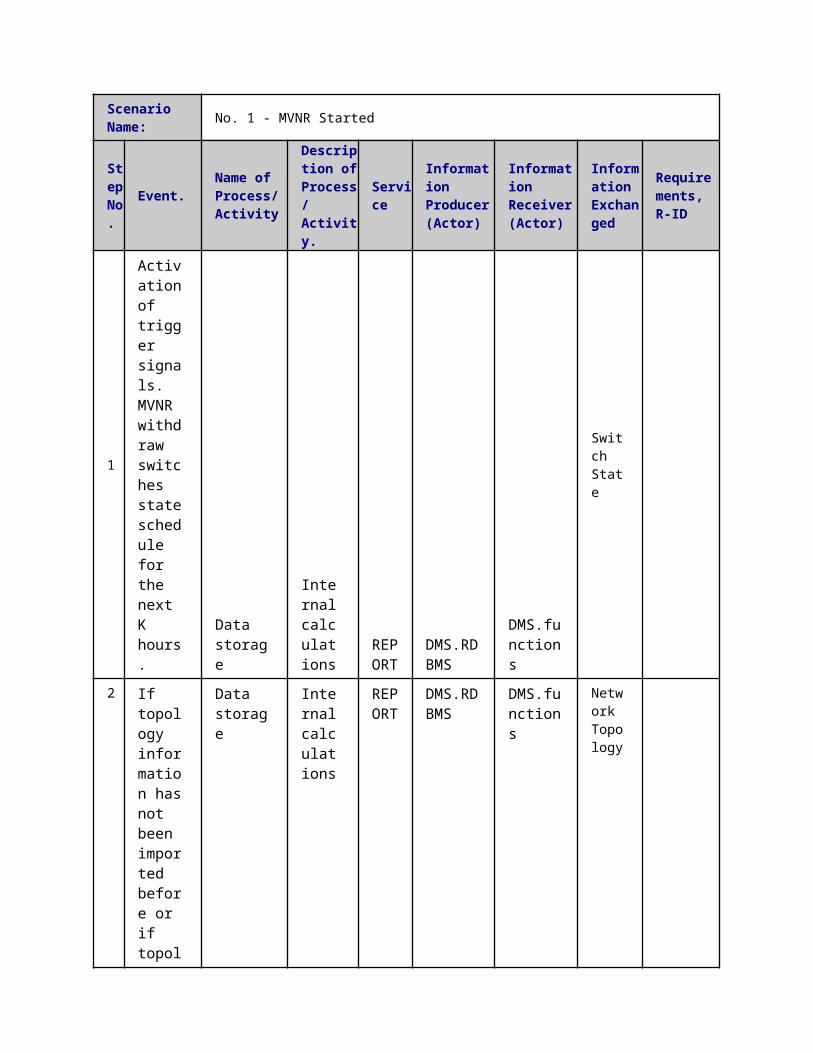
Key Value Refers to Section
1 Description of the Use Case1.1 Name of the Use Case
Use Case Identification
IDArea / Domain(s)/Zone(s)
Name of the Use Case
145 Decentralized FLISR
1.2 Version ManagementVersion Management
1.3 Scope and Objectives of Use CaseScope and Objectives of Use Case
ScopeAssessment of performance of fault detection, isolation and location algorithms designed for loop scheme network; even in MV grids with a high impact of DG connection.
Objective(s)
Related businesscase(s)
1.4 Narrative of Use CaseNarrative of Use CaseShort descriptionThe use case contemplates the detection process using relevant information for different types of faults. A distributed control functions is proposed in order to locate and isolate the part of the network that has been affected by acting on circuit breakers, switches and microgrid interconnection switches located along the feeder under test. Once the fault is located and isolated, the service restoration process will start.Complete descriptionThe steps are described below:1. When a fault happens in one of the areas covered by the feeder, IEDs distributed along the grid will detect it and will extract the fault related information as faulted phases, power flow direction, fault currents, faulted equipment, etc and send directly to peer protection IEDs and reporting it over to the central Primary Substation Data eXchange Platform (PSDXP). This process goes under the name of Fault information acquisition (FIA).2. The fault detection will trigger a communication process between peer IEDs, located within the area affected by the fault and the protection function which is operating within the Primary Substation Automation Unit (PSAU). The information received will be processed by each intelligent electronic device in order to determine the circuit breaker controller which is nearest the fault location. The opening of this CB will be commanded by its corresponding intelligent electronic device, as well as the block of the opening of the other CBs located along the faulted feeder. This procedure goes under the name of fault processing (FP) function.
3. With the Fault Information Acquisition (FIA) function, the decentralized IEDs controlling switches will communicate, among them and with the PSAU, the fault related information, allowing determining a more precise faulted section area, thus reducing the isolated area. Once the system reaches a steady configuration, all final state reports are sent to the PSAU to inform about the fault location and the current state of CB and Switches.
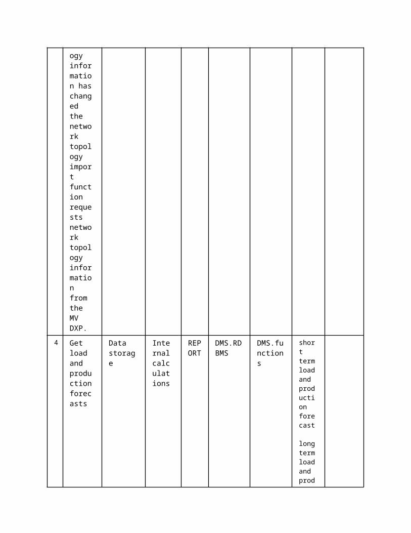
4. For the service restoration phase, IEDs will run a fast restoration algorithm in order to minimize the outage cost. This procedure goes also under the name Fault processing (FP). Once all possible costumers have been reenergized, a slow restoration algorithm will be performed in a centralized system, with the CCPC use case, in order to determine the optimum reconfiguration according to different cost functions.5. Data regarding the FLISR process and the new topology are stored, through DS function, in the local DXPs (Primary Substation Data eXchange Platform (PSDXP)).
1.5 General RemarksGeneral Remarks
2 Diagrams of Use Case
3 Technical Details3.1 Actors
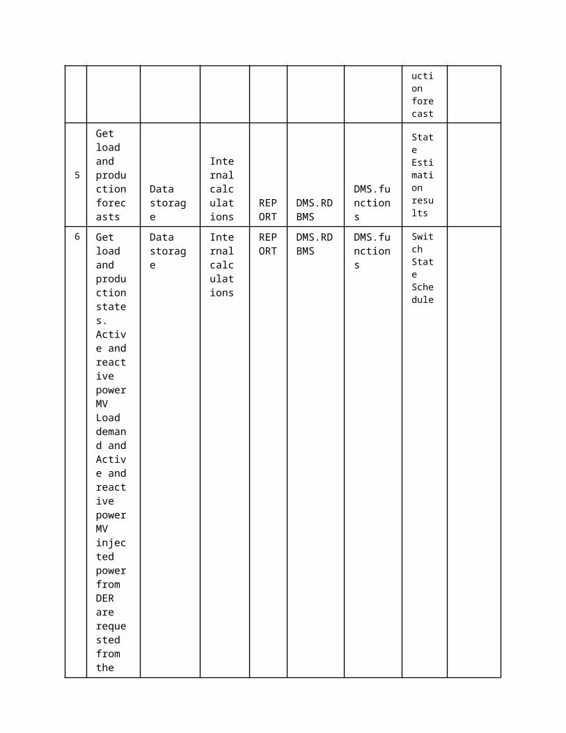
ActorsGrouping Group Description
Actor Name Actor Type Actor DescriptionFurther information specific to this Use Case
IED(BR-CTRL).functions
functionIED controlling a breaker
IED(BR-CTRL).MMS
function IED controlling a breaker, MMS interface
IED(SW-CTRL).GOOSE
function IED controlling a switch, GOOSE interface
MGCC.MMSfunction Microgrid central controller, MMS
interface
IED(BR-CTRL).GOOSE
function IED controlling a breaker, GOOSE interface
IED(SW-CTRL).functions
functionIED controlling a switch
IED.MMS function IED, MMS interface
IED.GOOSE function IED goose interface
IED(SW-CTRL).MMS
function IED controlling a switch, MMS interface
Actuator(BR) component Actuator, breaker
SAU(PSAU).MMS
function PSAU, MMS interface
3.2 Triggering Event, Preconditions, AssumptionsUse Case ConditionsActor/System/Information/Contract
Triggering Event
Pre-conditions Assumption
3.3 ReferencesReferences
No. References Type Reference Statu
sImpact on Use Case
Organistaor / Organisation
Link
3.4 Further Information to the Use Case for Classification / MappingClassification InformationRelation to Other Use CasesLevel of DepthPriorisationGeneric, Regional or National RelationViewpointFurther Keyword for Classification
4 Step by Step Analysis of Use Case4.1 Overview of Scenarios
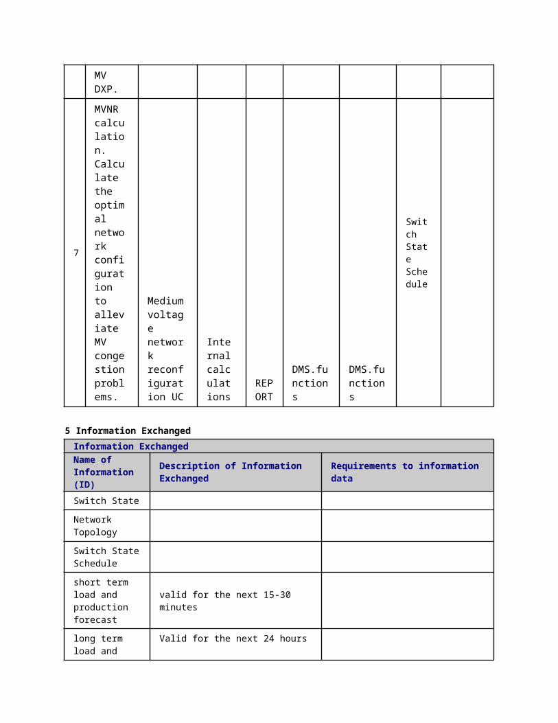
Scenario ConditionsNo.
Scenario Name Primary Actor Triggering Event Pre-Condition Post-Condition
4.2 Steps - ScenariosScenarioScenario Name: No. 1 - Fault event next to the breaker
Step No.
Event.
Name of Process/ Activity
Description of Process/ Activity.
Service
Information Producer (Actor)
Information Receiver (Actor)
Information Exchanged
Requirements, R-ID
1
Fault event detected
Fault detection
EXECUTE
IED(BR-CTRL).functions
IED(BR-CTRL).functions
Block message (block trip)
2 Trip delay START
Fault detection
TIMER
IED(BR-CTRL).functions
IED(BR-CTRL).functions
Block message (block trip)
3
Trip delay EXPIRED
Fault detection
TIMER
IED(BR-CTRL).functions
IED(BR-CTRL).functions
Block message (block trip)
4Breaker trip
open/close switch
EXECUTE
IED(BR-CTRL).functions
Actuator(BR)
Open / Close command (Open)
5 Trip reporting
Fault isolation
REPORT
IED(BR-CTRL).MMS
SAU(PSAU).MMS
Breaker or switch status (Open)
6MGCC keep connected
Fault isolation
EXECUTE
IED(BR-CTRL).MMS
MGCC.MMS
Block message (block disconnection)
7 MGCC disconnect
Fault isolation
EXECUTE
IED(BR-CTRL).MMS
MGCC.MMS
Block message (block connection)
8 DG Fault EXEC IED(BR- IED.GOOS Block

keep connected
isolation UTE
CTRL).GOOSE E
message (block disconnection)
9 DG disconnect
Fault isolation
EXECUTE
IED(BR-CTRL).GOOSE
IED.GOOSE
Block message (block connection)
10
Autoreclosing timer START
Second fault isolation
TIMER
IED(BR-CTRL).functions
IED(BR-CTRL).functions
Block message (block connection)
11
Autoreclosing timer EXPIRED
Second fault isolation
TIMER
IED(BR-CTRL).functions
IED(BR-CTRL).functions
Block message (block connection)
12
MG keep connected
Second fault isolation
EXECUTE
IED(BR-CTRL).MMS
MGCC.MMS
Block message (block disconnection)
13
DG keep connected
Second fault isolation
EXECUTE
IED(BR-CTRL).MMS IED.MMS
Block message (block disconnection)
14
Breaker reclosing process
open/close switch
EXECUTE
IED(BR-CTRL).functions
Actuator(BR)
Open / Close command (Close)
15
Isolation completed
Second fault isolation
REPORT
IED(BR-CTRL).MMS
SAU(PSAU).MMS
AutoReclosingSt
ScenarioScenario Name: No. 2 - Fault event solved by IED operating a switch
Step No.
Event. Name of Process/
Description of Proces
Service
Information Producer (Actor)
Information Receiver (Actor)
Information Exchanged
Requirements, R-ID

Activitys/ Activity.
1
Fault event detected
Fault isolation
EXECUTE
IED(BR-CTRL).functions
IED(BR-CTRL).functions
Block message (block trip)
2 Trip delay START
Fault isolation
TIMER
IED(BR-CTRL).functions
IED(BR-CTRL).functions
Block message (block trip)
3
Trip delay EXPIRED
Fault isolation
TIMER
IED(BR-CTRL).functions
IED(BR-CTRL).functions
Block message (block trip)
4Breaker trip
open/close switch
EXECUTE
IED(BR-CTRL).functions
Actuator(BR)
Open / Close command (Open)
5 Trip reporting
Fault isolation
REPORT
IED(BR-CTRL).MMS
SAU(PSAU).MMS
Breaker or switch status (Open)
6MGCC keep connected
Fault isolation
EXECUTE
MGCC.MMS
MGCC.MMS
Block message (block disconnection)
7 MGCC disconnect
Fault isolation
EXECUTE
MGCC.MMS
MGCC.MMS
Block message (block connection)
8DG keep connected
Fault isolation
EXECUTE
MGCC.MMS IED.MMS
Block message (block disconnection)
9 DG disconnect
Fault isolation
EXECUTE
MGCC.MMS IED.MMS
Block message (block connection)
1 Autorec Secon TIM IED(BR- IED(BR- Block
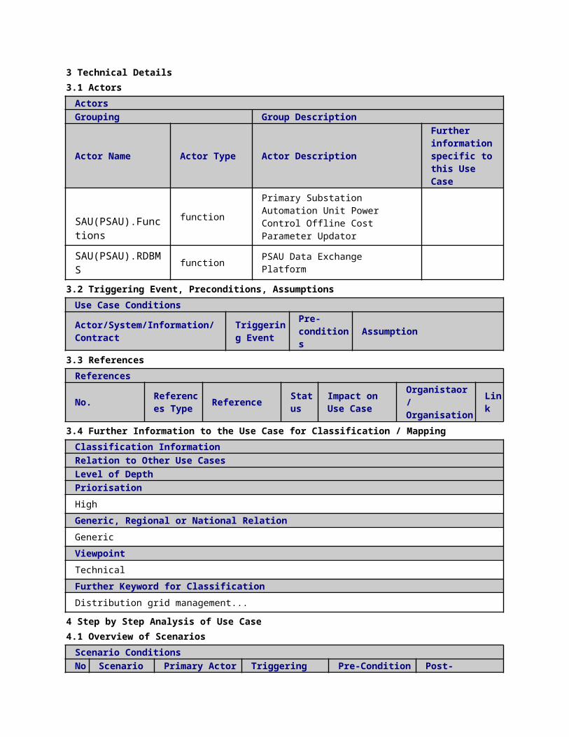
0 losing timer START
d fault isolation ER
CTRL).functions
CTRL).functions
message (block connection)
11
FPI block messages
Second fault isolation
EXECUTE
IED(SW-CTRL).GOOSE
IED.GOOSE
Block message (block trip)
12
Trip delay START
Second fault isolation
TIMER
IED(SW-CTRL).functions
IED(SW-CTRL).functions
Block message (block trip)
13
Trip delay EXPIRED
Second fault isolation
TIMER
IED(SW-CTRL).functions
IED(SW-CTRL).functions
Block message (block trip)
14 Switch
open
open/close switch
EXECUTE
IED(SW-CTRL).functions
Actuator(BR)
Open / Close command (Open)
15
Open reporting
Second fault isolation
REPORT
MGCC.MMS
SAU(PSAU).MMS
Breaker or switch status (Open)
16
MGCC keep connected
Second fault isolation
EXECUTE
MGCC.MMS
MGCC.MMS
Block message (block disconnection)
17 MGCC
unblock connect
Second fault isolation
EXECUTE
MGCC.MMS
MGCC.MMS
Block message (unblock connection)
18 MGCC
disconnect
Second fault isolation
EXECUTE
MGCC.MMS
MGCC.MMS
Block message (block connection)
19
DG keep connected
Second fault isolation
EXECUTE
MGCC.MMS IED.MMS
Block message (block disconnection)

20 DG
disconnect
Second fault isolation
EXECUTE
MGCC.MMS IED.MMS
Block message (block connection)
21
Autoreclosing timer EXPIRED
Second fault isolation
TIMER
IED(BR-CTRL).functions
IED(BR-CTRL).functions
Block message (block connection)
22
MG and DG keep connected
Second fault isolation
EXECUTE
IED(BR-CTRL).MMS
MGCC.MMS
Block message (block disconnection)
23
MG and DG keep connected
Second fault isolation
EXECUTE
IED(BR-CTRL).MMS IED.MMS
Block message (block disconnection)
24
Breaker reclosing process
Second fault isolation
EXECUTE
IED(BR-CTRL).functions
IED(BR-CTRL).functions
Open / Close command (Close)
25
Isolation completed
Second fault isolation
REPORT IED.MMS
SAU(PSAU).MMS
AutoReclosingSt
ScenarioScenario Name: No. 3 - Faulty breaker + Chronometric selectivity
Step No.
Event.
Name of Process/ Activity
Description of Process/ Activity.
Service
Information Producer (Actor)
Information Receiver (Actor)
Information Exchanged
Requirements, R-ID
1
Fault event detected
Fault isolation
EXECUTE
IED.GOOSE
IED.GOOSE
Block message (block trip)
2 Trip delay
Fault isolati
TIMER
IED(BR-CTRL).fun
IED(BR-CTRL).func
Block message
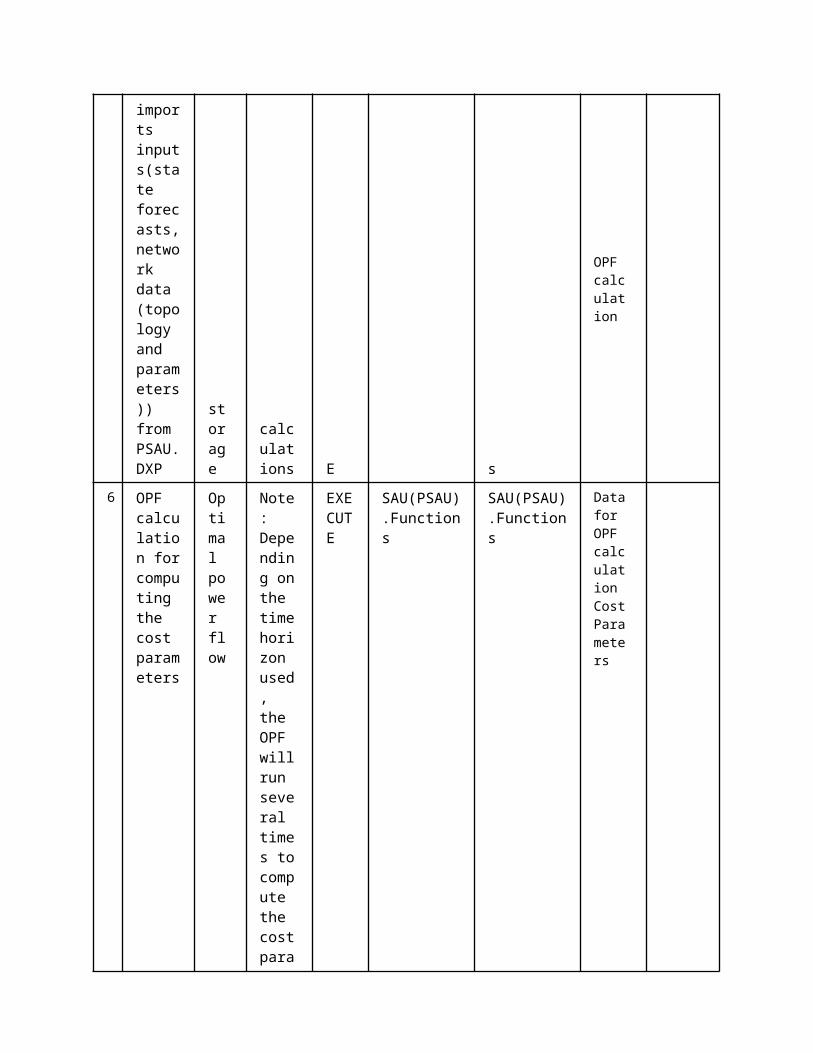
START on ctions tions(block trip)
3
Fault event block from another CB
Fault isolation
EXECUTE
IED(BR-CTRL).functions
IED(BR-CTRL).functions
Block message (block trip)
4 Breaker fail report
Fault isolation
REPORT
IED.GOOSE
IED.GOOSE
Breaker or switch status (Trouble)
5
Trip delay EXPIRED
Fault isolation
TIMER
IED(BR-CTRL).functions
IED(BR-CTRL).functions
Breaker or switch status (Trouble)
6Breaker trip
open/close switch
EXECUTE
IED(BR-CTRL).functions
Actuator(BR)
Open / Close command (Open)
7 Trip reporting
Fault isolation
REPORT IED.MMS
SAU(PSAU).MMS
Breaker or switch status (Open)
8MGCC keep connected
Fault isolation
EXECUTE IED.MMS
MGCC.MMS
Block message (block disconnection)
9 MGCC disconnect
Fault isolation
EXECUTE IED.MMS
MGCC.MMS
Block message (block connection)
10
DG keep connected
Fault isolation
EXECUTE
IED.GOOSE
IED.GOOSE
Block message (block disconnection)
11 DG
disconnect
Fault isolation
EXECUTE
IED.GOOSE
IED.GOOSE
Block message (block connection)
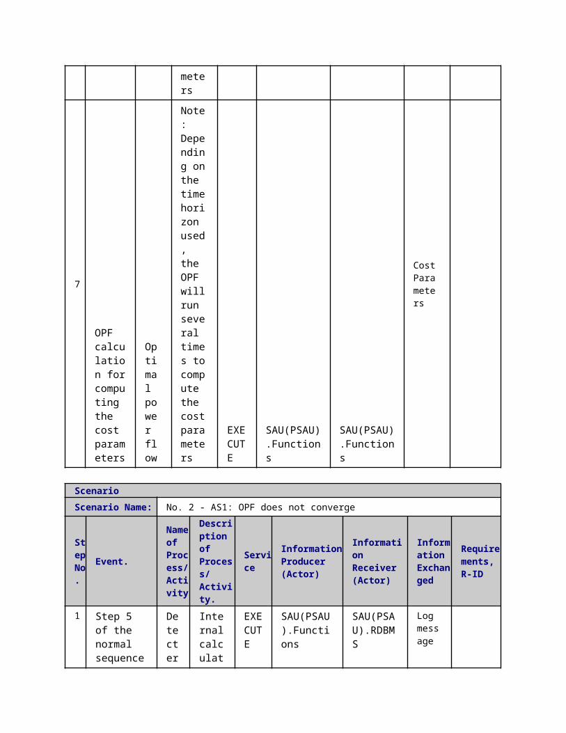
12
Autoreclosing timer START
Second fault isolation
TIMER
IED(BR-CTRL).functions
IED(BR-CTRL).functions
Block message (block connection)
13
FPI block messages
Second fault isolation
EXECUTE
IED.GOOSE
IED.GOOSE
Block message (block trip)
14
Trip delay START
Second fault isolation
TIMER
IED(SW-CTRL).functions
IED(SW-CTRL).functions
Block message (block trip)
15
Trip delay EXPIRED
Second fault isolation
TIMER
IED(SW-CTRL).functions
IED(SW-CTRL).functions
Block message (block trip)
16 Switch
trip
open/close switch
EXECUTE
IED(SW-CTRL).functions
Actuator(BR)
Open / Close command (Open)
17
Trip reporting
Second fault isolation
REPORT IED.MMS
SAU(PSAU).MMS
Breaker or switch status (Open)
18
MGCC keep connected
Second fault isolation
EXECUTE IED.MMS
MGCC.MMS
Block message (block disconnection)
19 MGCC
unblock connect
Second fault isolation
EXECUTE IED.MMS
MGCC.MMS
Block message (unblock connection)
20 MGCC
disconnect
Second fault isolation
EXECUTE
IED.GOOSE
IED.GOOSE
Block message (block connection)
21
DG keep connected
Second fault isolation
EXECUTE
IED.GOOSE
IED.GOOSE
Block message (block disconnec
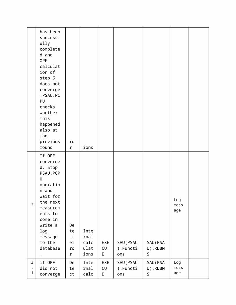
tion)
22 DG
disconnect
Second fault isolation
EXECUTE
IED.GOOSE
IED.GOOSE
Block message (block connection)
23
Autoreclosing timer EXPIRED
Second fault isolation
TIMER
IED(BR-CTRL).functions
IED(BR-CTRL).functions
Block message (block connection)
24
MG and DG keep connected
Second fault isolation
EXECUTE
IED(BR-CTRL).MMS
MGCC.MMS
Block message (block disconnection)
25
MG and DG keep connected
Second fault isolation
EXECUTE
IED(BR-CTRL).functions
IED.GOOSE
Block message (block disconnection)
26
Breaker reclosing process
Second fault isolation
EXECUTE
IED(BR-CTRL).functions
IED(BR-CTRL).functions
Open / Close command (Close)
27
Isolation complete
Second fault isolation
REPORT
IED(BR-CTRL).MMS
SAU(PSAU).MMS
AutoReclosingSt
ScenarioScenario Name: No. 4 - Fault event solved by IED operating a switch
Step No.
Event.
Name of Process/ Activity
Description of Process/ Activity.
Service
Information Producer (Actor)
Information Receiver (Actor)
Information Exchanged
Requirements, R-ID
1
Fault event detected
Fault isolation
EXECUTE
IED(BR-CTRL).functions
IED(BR-CTRL).functions
Block message (block trip)
2 Trip Fault TIM IED(BR- IED(BR- Block
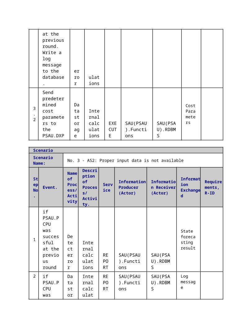
delay START
isolation ER
CTRL).functions
CTRL).functions
message (block trip)
3
Trip delay EXPIRED
Fault isolation
TIMER
IED(BR-CTRL).functions
IED(BR-CTRL).functions
Block message (block trip)
4Breaker trip
open/close switch
EXECUTE
IED(BR-CTRL).functions
Actuator(BR)
Open / Close command (Open)
5 Trip reporting
Fault isolation
REPORT
IED(BR-CTRL).MMS
SAU(PSAU).MMS
Breaker or switch status (Open)
6MGCC keep connected
Fault isolation
EXECUTE
IED(BR-CTRL).MMS
MGCC.MMS
Block message (block disconnection)
7 MGCC disconnect
Fault isolation
EXECUTE
IED(BR-CTRL).MMS
MGCC.MMS
Block message (block connection)
8DG keep connected
Fault isolation
EXECUTE
IED(BR-CTRL).GOOSE
IED.GOOSE
Block message (block disconnection)
9 DG disconnect
Fault isolation
EXECUTE
IED(BR-CTRL).GOOSE
IED.GOOSE
Block message (block connection)
10
Autoreclosing timer START
Second fault isolation
TIMER
IED(BR-CTRL).functions
IED(BR-CTRL).functions
Block message (block connection)
11
FPI block messages
Second fault isolation
EXECUTE
IED.GOOSE
IED.GOOSE
Block message (block trip)
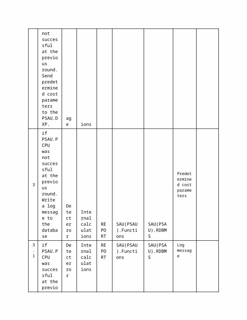
13
Trip delay START
Second fault isolation
TIMER
IED(SW-CTRL).functions
IED(SW-CTRL).functions
Block message (block trip)
14
Fault event block from another FPI
Second fault isolation
EXECUTE
IED(SW-CTRL).functions
IED(SW-CTRL).functions
Block message (block trip)
15
Switch fail report
Second fault isolation
REPORT
IED(SW-CTRL).MMS
SAU(PSAU).MMS
Breaker or switch status (Trouble)
16
Trip delay EXPIRED
Second fault isolation
TIMER
IED(SW-CTRL).functions
IED(SW-CTRL).functions
Breaker or switch status (Trouble)
17 Switch
open
open/close switch
EXECUTE
IED(SW-CTRL).functions
Actuator(BR)
Open / Close command (Open)
18
Open status reporting
Second fault isolation
REPORT
IED(SW-CTRL).MMS
SAU(PSAU).MMS
Breaker or switch status (Open)
19
MGCC keep connected
Second fault isolation
EXECUTE
IED(SW-CTRL).MMS
MGCC.MMS
Block message (block disconnection)
20 MGCC
unblock connect
Second fault isolation
EXECUTE
IED(SW-CTRL).MMS
MGCC.MMS
Block message (unblock connection)
21 MGCC
disconnect
Second fault isolation
EXECUTE
IED(SW-CTRL).MMS
MGCC.MMS
Block message (block connection)
22
DG keep connect
Second fault isolati
EXECUTE
IED(SW-CTRL).GOOSE
IED.GOOSE
Block message (block
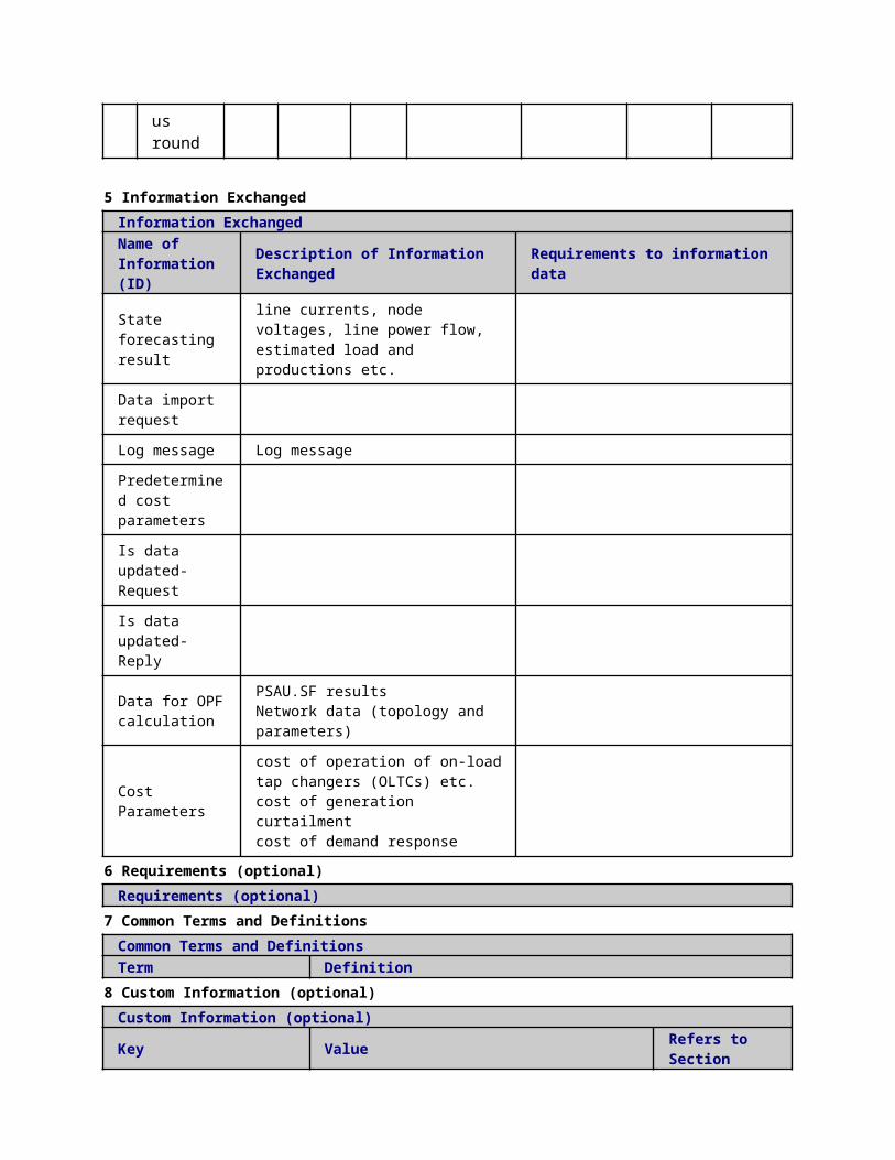
ed ondisconnection)
23 DG
disconnect
Second fault isolation
EXECUTE
IED(SW-CTRL).GOOSE
IED.GOOSE
Block message (block connection)
24
Autoreclosing timer EXPIRED
Second fault isolation
TIMER
IED(BR-CTRL).functions
IED(BR-CTRL).functions
Block message (block connection)
25
MG and DG keep connected
Second fault isolation
EXECUTE
IED(BR-CTRL).MMS
MGCC.MMS
Block message (block disconnection)
26
MG and DG keep connected
Second fault isolation
EXECUTE
IED(BR-CTRL).GOOSE
IED.GOOSE
Block message (block disconnection)
27
Breaker reclosing process
Second fault isolation
EXECUTE
IED(BR-CTRL).functions
IED(BR-CTRL).functions
Open / Close command (Close)
28
Isolation completed
Second fault isolation
REPORT
IED(BR-CTRL).MMS
SAU(PSAU).MMS
AutoReclosingSt
ScenarioScenario Name: No. 5 - Failure in single breaker communication
Step No.
Event.
Name of Process/ Activity
Description of Process/ Activity.
Service
Information Producer (Actor)
Information Receiver (Actor)
Information Exchanged
Requirements, R-ID
1
Fault event detected
Fault isolation
EXECUTE
IED(BR-CTRL).functions
IED(BR-CTRL).functions
Block message (block trip)

2 Trip delay START
Fault isolation
TIMER
IED(BR-CTRL).functions
IED(BR-CTRL).functions
Block message (block trip)
3
Fault event block from another CB NOT Received
Fault isolation
EXECUTE
IED(BR-CTRL).functions
IED(BR-CTRL).functions
Block message (block trip)
4
Trip delay EXPIRED in prioritary breaker
Fault isolation
TIMER
IED(BR-CTRL).functions
IED(BR-CTRL).functions
Block message (block trip)
5
Trip delay EXPIRED
Fault isolation
TIMER
IED(BR-CTRL).functions
IED(BR-CTRL).functions
Block message (block trip)
6
Prioritary breaker trip
Fault isolation
EXECUTE
IED(BR-CTRL).functions
IED(BR-CTRL).functions
Open / Close command (Open)
7Breaker trip
open/close switch
EXECUTE
IED(BR-CTRL).functions
Actuator(BR)
Open / Close command (Open)
8
Trip reporting by prioritary breaker
Fault isolation
REPORT
IED(BR-CTRL).functions
SAU(PSAU).MMS
Breaker or switch status (Open)
9 Trip reporting
Fault isolation
REPORT
IED(BR-CTRL).functions
SAU(PSAU).MMS
Breaker or switch status (Open)
10
MGCC keep connect
Fault isolation
EXECUTE
IED(BR-CTRL).MMS
MGCC.MMS
Block message (block
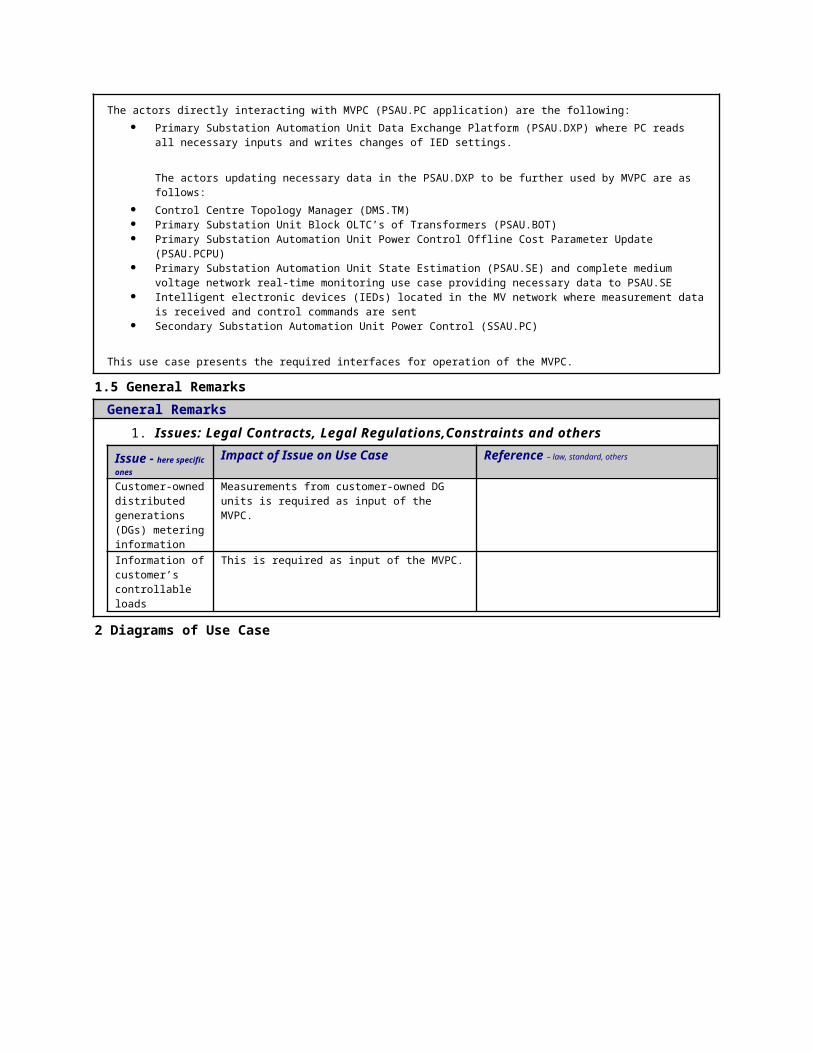
ed by prioritary breaker
disconnection)
11
MGCC keep connected
Fault isolation
EXECUTE
IED(BR-CTRL).MMS
MGCC.MMS
Block message (block disconnection)
12
MGCC disconnect by prioritary breaker
Fault isolation
EXECUTE
IED(BR-CTRL).MMS
MGCC.MMS
Block message (block connection)
13 MGCC
disconnect
Fault isolation
EXECUTE
IED(BR-CTRL).MMS
MGCC.MMS
Block message (block connection)
14
DG keep connected by prioritary breaker
Fault isolation
EXECUTE
IED(BR-CTRL).GOOSE
IED.GOOSE
Block message (block disconnection)
15
DG keep connected
Fault isolation
EXECUTE
IED(BR-CTRL).GOOSE
IED.GOOSE
Block message (block disconnection)
16
DG disconnect by prioritary breaker
Fault isolation
EXECUTE
IED(BR-CTRL).GOOSE
IED.GOOSE
Block message (block connection)
17 DG
disconnect
Fault isolation
EXECUTE
IED(BR-CTRL).GOOSE
IED.GOOSE
Block message (block connection)
1 Autorec Secon TIM IED(BR- IED(BR- Block

8 losing timer START
d fault isolation ER
CTRL).functions
CTRL).functions
message (block connection)
19
FPI block messages
Second fault isolation
EXECUTE
IED(SW-CTRL).functions
IED.GOOSE
Block message (block trip)
20
Trip delay START
Second fault isolation
TIMER
IED(SW-CTRL).functions
IED(SW-CTRL).functions
Block message (block trip)
21
Trip delay EXPIRED
Second fault isolation
TIMER
IED(SW-CTRL).functions
IED(SW-CTRL).functions
Block message (block trip)
22 Switch
trip
open/close switch
EXECUTE
IED(SW-CTRL).functions
Actuator(BR)
Open / Close command (Open)
23
Trip reporting
Second fault isolation
REPORT
IED(SW-CTRL).MMS
SAU(PSAU).MMS
Breaker or switch status (Open)
24
MGCC keep connected
Second fault isolation
EXECUTE
IED(SW-CTRL).MMS
MGCC.MMS
Block message (block disconnection)
25 MGCC
unblock connect
Second fault isolation
EXECUTE
IED(SW-CTRL).MMS
MGCC.MMS
Block message (unblock connection)
26 MGCC
disconnect
Second fault isolation
EXECUTE
IED(SW-CTRL).MMS
MGCC.MMS
Block message (block connection)
27
DG keep connected
Second fault isolation
EXECUTE
IED(SW-CTRL).functions
IED.GOOSE
Block message (block disconnection)

28 DG
disconnect
Second fault isolation
EXECUTE
IED(SW-CTRL).GOOSE
IED.GOOSE
Block message (block connection)
29
Autoreclosing timer EXPIRED in prioritary breaker
Second fault isolation
EXECUTE
IED(BR-CTRL).GOOSE
IED.GOOSE
Block message (block connection)
30
Autoreclosing timer EXPIRED
Second fault isolation
TIMER
IED(BR-CTRL).functions
IED(BR-CTRL).functions
Block message (block connection)
31
MG and DG keep connected by prioritary breaker
Second fault isolation
EXECUTE
IED(BR-CTRL).MMS
MGCC.MMS
Block message (block disconnection)
32
MG and DG keep connected by prioritary breaker
Second fault isolation
EXECUTE
IED(BR-CTRL).GOOSE
IED.GOOSE
Block message (block disconnection)
33
MG and DG keep connected
Second fault isolation
EXECUTE
IED(BR-CTRL).MMS
MGCC.MMS
Block message (block disconnection)
34
MG and DG keep connected
Second fault isolation
EXECUTE
IED(BR-CTRL).GOOSE
IED.GOOSE
Block message (block disconnection)
3 Prirority open/ EXEC IED(BR- Actuator( Open /

5
Breaker reclosing process
close switch UTE
CTRL).functions BR)
Close command (Close)
36
Breaker reclosing process
open/close switch
EXECUTE
IED(BR-CTRL).functions
Actuator(BR)
Open / Close command (Close)
37
Isolation complete
Second fault isolation
REPORT
IED(BR-CTRL).MMS
SAU(PSAU).MMS
AutoReclosingSt
5 Information ExchangedInformation ExchangedName of Information (ID)
Description of Information Exchanged Requirements to information data
Open / Close command
Open or trip commandClose command
Breaker or switch status
OpenClose Trouble
Isolation complete
Block message XCBR -Block openXCBR -Block close
AutoreclosingStMessage reporting a status change in the local autoreclosing function. Active/Inactive
1 Description of the Use Case1.1 Name of the Use Case
Use Case Identification
IDArea / Domain(s)/Zone(s)
Name of the Use Case
144 Microgrid FLISR
1.2 Version ManagementVersion Management
1.3 Scope and Objectives of Use CaseScope and Objectives of Use Case
ScopeThis use case explains the disconnection of a microgrid from the MV distribution grid responding to a status change and analyzes the reconnection to the distribution grid after fault restoration.
Objective(s) The objective of this use case is to help to develop an isolation switch capable of
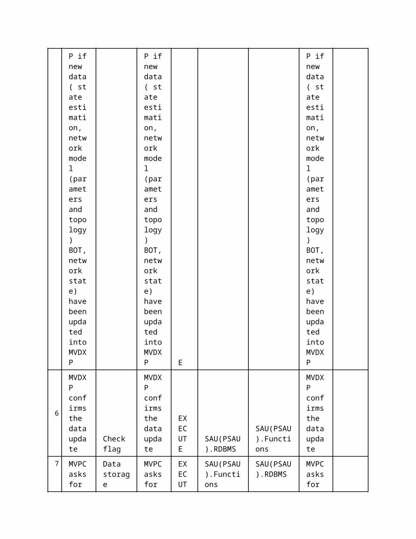
isolating microgrids.
Related businesscase(s)
1.4 Narrative of Use CaseNarrative of Use CaseShort descriptionThis use case explains the disconnection of a microgrid from the MV or LV distribution grid responding to a status change and analyzes the reconnection to the distribution grid after fault restoration. The isolation of microgrids will allow the continuity of the service in case of contingencies in the distribution network.Complete descriptionMicrogrids can be classified as urban microgrids and rural microgrids, given that the main difference is the point of common coupling (PCC). Urban microgrids are typically connected on a dedicated feeder of the secondary substation, whereas the rural microgrids are connected directly to a MV line through a step-down transformer. All microgrids are connected to the distribution grid through an Interconnection Switch (IS), which in the following description is classified as an IED actor, i.e. the physical element which isolates the microgrid, which consequently defines permanently the borders of the micro grid, as IED.IS.
The IS is a smart power switch capable to detect a local (near the PCC) fault in the MV or LV distribution grid or to receive disconnection orders from a higher level agent, such as the microgrid aggregator, the PSAU, or the SSIED.PD. The steps are described as follows:
1. In case of contingencies in the distribution network, the DIED.SWITCH autonomously isolates the microgrid, informing Microgrid central controller (MGCC), by sending a signal with the function Compute Control Signals (SCSs).
2. Messages will be sent from the MGCC to PSAU, with the function Fault Information Acquisition (FIA), to inform it about microgrid status.3. In island mode, the microgrid has its own local primary control, situated at the DIED.CTRL.MGLC, stabilizing the voltage and frequency of the isolated electrical area. In addition to the primary control, there is an energy management system (EMS) optimizing the internal power flow. This process requires the monitoring of electrical quantities, with function Measurement Acquisition (MA), their checking with Check Status of Electrical Variables (CSEV) function, and some control algorithms, which go under the Control function “CF” set. The control actions are communicated to DIED.CTRL.MGLC through “compute control signals” (SCS) function.4. During island mode, the MGCC keeps on monitoring the distribution grid to detect whether the fault has been cleared or not, with the Fault Information Acquisition (FIA) function; moreover, MGCC can receive inputs from SSIED.PD.SW or SSIED.PD.BRK indicating the fault has been cleared. These operations go under the function FIA.5. After the fault has been cleared, the microgrid is coordinated by the microgrid EMS, which goes under the function Control Functions (CFs), situated at MCC level, to synchronize with the distribution grid voltage phase and frequency. Then, DIED.Switch is comanded to resume electrical connection with the rest of the grid, through Compute Control Signals (SCSs) function.6. Information about the new state of the microgrid is send to the PSAU.
1.5 General RemarksGeneral Remarks
2 Diagrams of Use Case


3 Technical Details3.1 Actors
ActorsGrouping Group Description
Actor Name Actor Type Actor DescriptionFurther information specific to this Use Case
MGCC.Modbusfunction
Centralized microgrid controller aimed to manage the microgrid to perform the reconnection protocol.Modbus interface
SAU(PSAU).MMS
function PSAU, MMS interface
IED.MMS
function
Def. 1Intelligent Electronic Device located at the distribution network providing capabilities to implement the FLISR .MMS Interface
MGCC.MMS function MGCC, MMS interface
MGCC.RDBMS function MGCC, Database
MGCC.Functions
function Reclosure function of MGCC
IED(DIED-IS-CTRL).Modbus
function
Controller interconnection switchMicrogrid Intelligent Electronic Device operating the Interconnection Switch (DIED.SWITCH)Modbus interface
SAU(SSAU).MMS
function SSAU, MMS interface
IED(BR-CTRL).MMS
function IED, managing the breaker, MMS interface
IED(DIED-IS-CTRL).functions
function Controller interconnection switch
Actuator(IS-CTRL)
component Actuator of interconnection switch
3.2 Triggering Event, Preconditions, AssumptionsUse Case ConditionsActor/System/Information/Contract
Triggering Event
Pre-conditions Assumption
3.3 ReferencesReferences
No. References Type Reference Statu
sImpact on Use Case
Organistaor / Organisation
Link
3.4 Further Information to the Use Case for Classification / Mapping
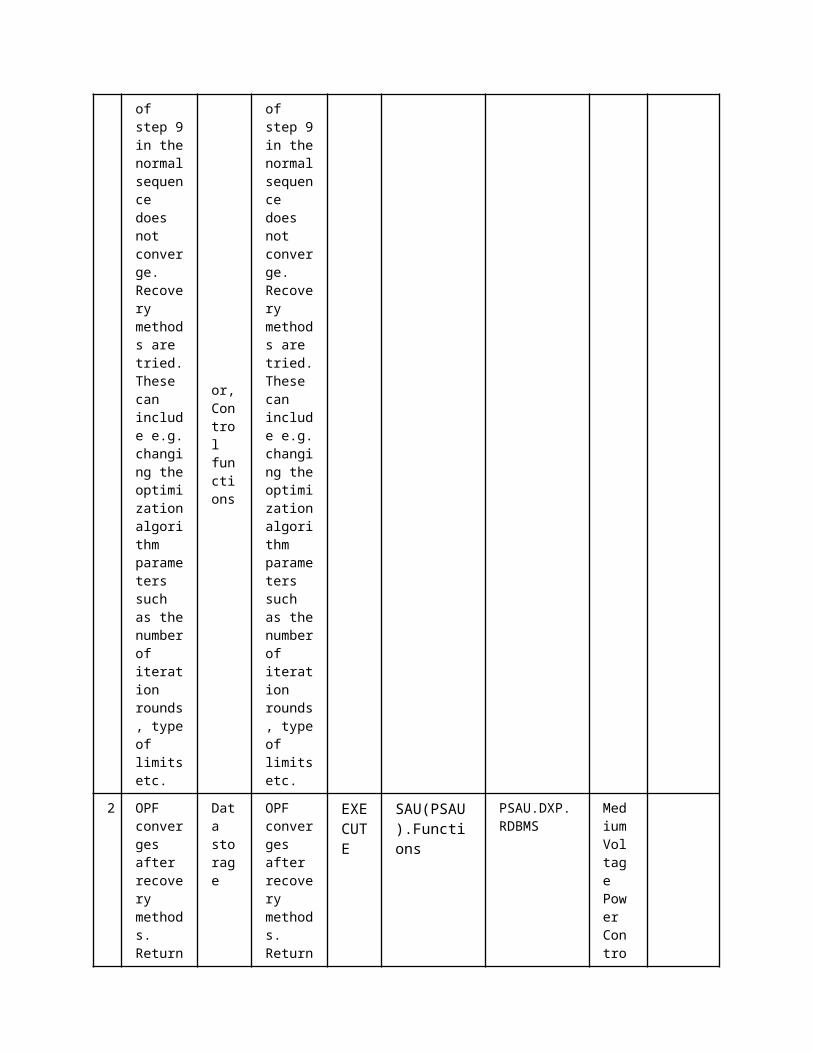
Classification InformationRelation to Other Use CasesLevel of DepthPriorisationGeneric, Regional or National RelationViewpointFurther Keyword for Classification
4 Step by Step Analysis of Use Case4.1 Overview of Scenarios
Scenario ConditionsNo.
Scenario Name Primary Actor Triggering Event Pre-Condition Post-Condition
4.2 Steps - ScenariosScenarioScenario Name: No. 1 - local fault detection
Step No.
Event.
Name of Process/ Activity
Description of Process/ Activity.
Service
Information Producer (Actor)
Information Receiver (Actor)
Information Exchanged
Requirements, R-ID
1
Microgrid isolation information
Data report
The microgrid DIED.SWITCH detects a tripping condition and isolates the microgrids informing the micrgrid central controller MGCC
REPORT
IED(DIED -IS-CTRL).Modbus
MGCC.Modbus
Breaker or switch status
2 Inform Secondary Substation about isolation
Data report
The microgrid informs the secondary substatio
REPORT
MGCC.MMS
SAU(SSAU).MMS
Breaker or switch status
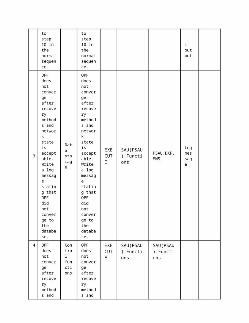
n that has been isolated
ScenarioScenario Name: No. 2 - SSIED.PD blocks isolation
Step No.
Event.Name of Process/ Activity
Description of Process/ Activity.
Service
Information Producer (Actor)
Information Receiver (Actor)
Information Exchanged
Requirements, R-ID
1
remote fault occurs, FLISR sends block (opening) signal
Reading/Writing IEDs setting
The FLISR commands the MGCC to block the interconnection switch to remain connected to the distribution grid.
REPORT
SAU(SSAU).MMS
MGCC.MMS
Block message
2
block IS
Reading/Writing IEDs setting
The MCC informs the microgrid IED (IS) to stay closed during the remote fault
REPORT
MGCC.Modbus
IED(DIED -IS-CTRL).Modbus
Block message
3 block signal received
Reading/Writing IEDs setting
The MGCC has received the block signal from the FLISR and forwards it to the interconnection
REPORT
IED(DIED -IS-CTRL).Modbus
MGCC.Modbus
Block message
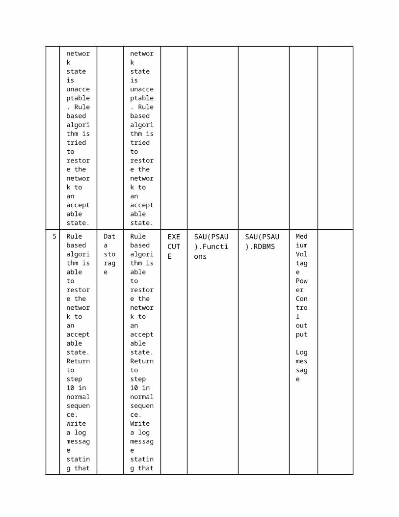
switch DIED.SWITCH
ScenarioScenario Name: No. 3 - Primary substation request status of the microgrid (connected or not)
Step No.
Event.
Name of Process/ Activity
Description of Process/ Activity.
Service
Information Producer (Actor)
Information Receiver (Actor)
Information Exchanged
Requirements, R-ID
1
update MGCC status
Reading/Writing IEDs setting
The MGCC updates its internal status vector by polling al IED from the microgrid
GET
IED(DIED -IS-CTRL).Modbus
MGCC.Modbus
Breaker or switch status
2
update MGCC status
Data storage
The MGCC updates its internal status vector by polling al IED from the microgrid
GET
MGCC.Modbus
MGCC.RDBMS
Breaker or switch status
3 update PSAU with info.
Data report
The PSAU requests updated information
GET
MGCC.MMS
SAU(PSAU).MMS
Breaker or switch status
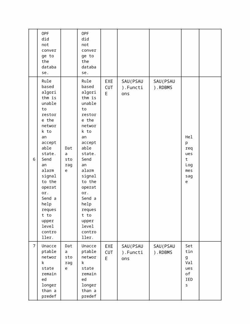
from MGCC
form MGCC
ScenarioScenario Name: No. 4 - Grid reconnection
Step No.
Event.Name of Process/ Activity
Description of Process/ Activity.
Service
Information Producer (Actor)
Information Receiver (Actor)
Information Exchanged
Requirements, R-ID
1
PSAU informs MCC about a fault that has been cleared
Data report
The secondary substations informs that the fault has been cleared and allows the microgrid to reconnect to the distribution grid
REPORT
SAU(PSAU).MMS
MGCC.MMS
Breaker or switch status
2microgrid synchronizes with dist. grid
synchronization
The MCC commands microgrid IED to sync with the distribution grid.
EXECUTE
MGCC.Modbus
IED(DIED).Modbus
Breaker or switch status
3 IS Reading/ the IS REP IED(DIED MGCC.Mo Brea
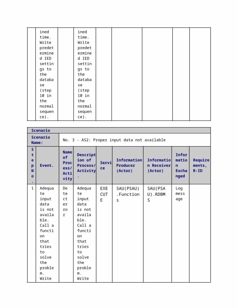
closes
Writing IEDs setting
closes autonomously upon sync of microgrid with dist. grid and informs the MCC ORT
-IS-CTRL).Modbus dbus
ker or switch status
4inform secondary substation
Reading/Writing IEDs setting
The MCC informs the SSIED that the microgrid has been reconnected
REPORT
MGCC.MMS
SAU(SSAU).MMS
Breaker or switch status
ScenarioScenario Name: No. 5 - Remote disconnection
Step No.
Event.Name of Process/ Activity
Description of Process/ Activity.
Service
Information Producer (Actor)
Information Receiver (Actor)
Information Exchanged
Requirements, R-ID
1
IED.BRK sends block (closing)
Reading/Writing IEDs setting
FLISR decides the microgrid should disconnect
EXECUTE
IED(BR-CTRL).MMS
MGCC.MMS
Block message
2transmits command
Reading/Writing IEDs setting
MCC sends command to the IS
EXECUTE
MGCC.Modbus
IED(DIED-IS-CTRL).Modbus
Block message
3 command
open/close
The micro
EXECUTE
IED(DIED-IS-
Actuator(IS-CTRL)
Block mess
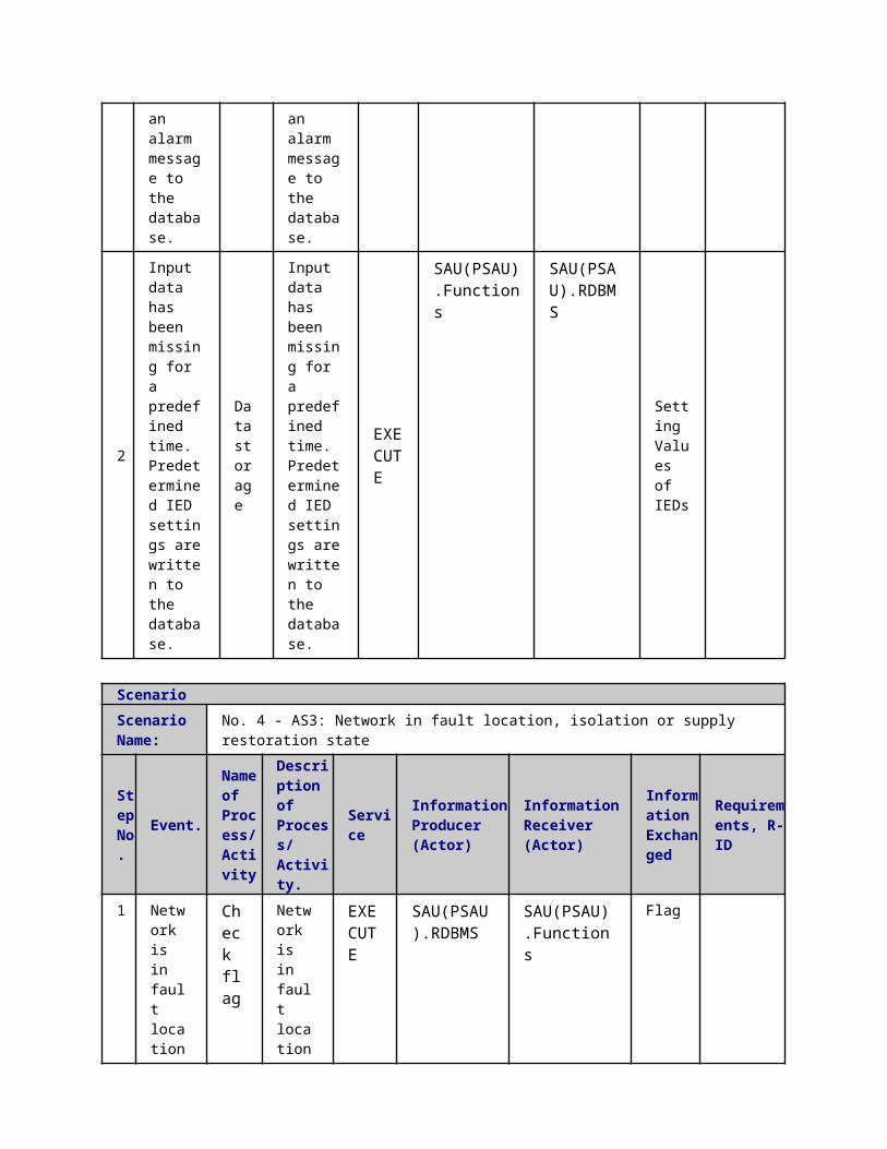
received - execute isolation switch
grids becomes isolated
CTRL).functions
age
ScenarioScenario Name: No. 6 - Conflicting commands
Step No.
Event.Name of Process/ Activity
Description of Process/ Activity.
Service
Information Producer (Actor)
Information Receiver (Actor)
Information Exchanged
Requirements, R-ID
1
received flag keep connected (block open)
Reading/Writing IEDs setting
SSIED.PD sends a flag to MGCC to block open, i.e. remain connected to distribution grid
EXECUTE IED.MMS
MGCC.MMS
received flag keep connected (block open)
2 received flag keep disconnected, block (close)
Reading/Writing IEDs setting
SSIED.PD sends a block close command to MDCC, i.e. remain disconnect from
EXECUTE
IED.MMS MGCC.MMS
received flag keep disconnected, block (close)

distribution grid
3
resolve control conflict
Detect error
MGCC detects conflict in flags from SSIED.PD and triggers isolation of the microgrid
EXECUTE
MGCC.Functions
MGCC.RDBMS
Block message
4
resolve conflict
Reading/Writing IEDs setting
MGCC detects conflict in flags from SSIED.PD and triggers isolation of the microgrid
EXECUTE
MGCC.Modbus
IED(DIED-IS-CTRL).Modbus
Block message
5
isolate / keep connected microgrid
Reading/Writing IEDs setting
IS opens and isolates microgrid
EXECUTE
MGCC.Modbus
IED(DIED-IS-CTRL).Modbus
Block message
6 isolation
open/close
IS opens
EXECUT
IED(DIED-IS-
Actuator(IS-
Block messag
switch
and isolates microgrid E
CTRL).functions CTRL) e
5 Information ExchangedInformation ExchangedName of Information (ID)
Description of Information Exchanged Requirements to information data
Breaker or switch status
OpenClose Trouble
Block message XCBR -Block openXCBR -Block close
1 Description of the Use Case1.1 Name of the Use Case
Use Case Identification
IDArea / Domain(s)/Zone(s)
Name of the Use Case
150 Real-Time Validation (RTV)
1.2 Version ManagementVersion Management
1.3 Scope and Objectives of Use CaseScope and Objectives of Use Case
ScopeThis use case shows the interaction between the aggregators and the DSO.Technical aggregators required to validate the technical feasibility of the activation of flexibility products in the short term (15 mintues in advance).
Objective(s) The objective of this use case is to validate the activation of CRPs previously validated by the Off-Line Validation (OLV) whose activation is required
Related businesscase(s)
1.4 Narrative of Use CaseNarrative of Use CaseShort descriptionThe core procedure is almost the same as in the OLV tool. The main difference is that this Tool is used for products traded during the intra-day market and for CRPs that are activated by the CA at any time of the day. Due to the close to real-time use of this Tool (i.e. 15 minutes before the deployment), the real description of the system is used (topology, load, generation etc.)Complete description
1. DR ProductsRTV Re-checks the feasibility of
CRPs previously validated by the Off-Line Validation (OLV), whose activation is required
NOT the SRP products already validated by OLV. They are considered as activated.
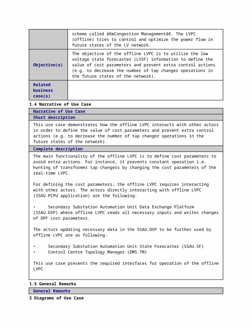
NOT the CRP products activated by the DSO.Technical aggregator2. Sequence Description:
The RTV is used by both the DSO.Technical aggregator and the TSO. The procedure that is followed is:
First, the CA submits the bids to be Validated by the DSO.Technical aggregator The DSO.Technical aggregator aggregates the bids per Load Area and validates
them. If needed, a curtailment factor is applied The DR products are aggregated per Macro Load Area (MLA) and sent to the TSO. The validation procedure is repeated by the TSO A final validation or curtailment factor is applied, by combining the response of both
the DSO.Technical aggregator and the TSO. The combined responses of the DSO-TA and the TSO, i.e. the acceptance reply or
the curtailment factor per load area, are sent to the CAs involved.3. Time Frame
This process is repeated every 15 minutes4. Differences with OLV
The differences with the OLV algorithm are that: Only the CRPs to be activated are checked. The previously validated SRPs are considered
as validated. The real network topology is now used for the Power flow. The RTV algorithm applies corrective actions for the voltage control trying to maximize DR
products feasibility.
1.5 General RemarksGeneral Remarks
2 Diagrams of Use Case
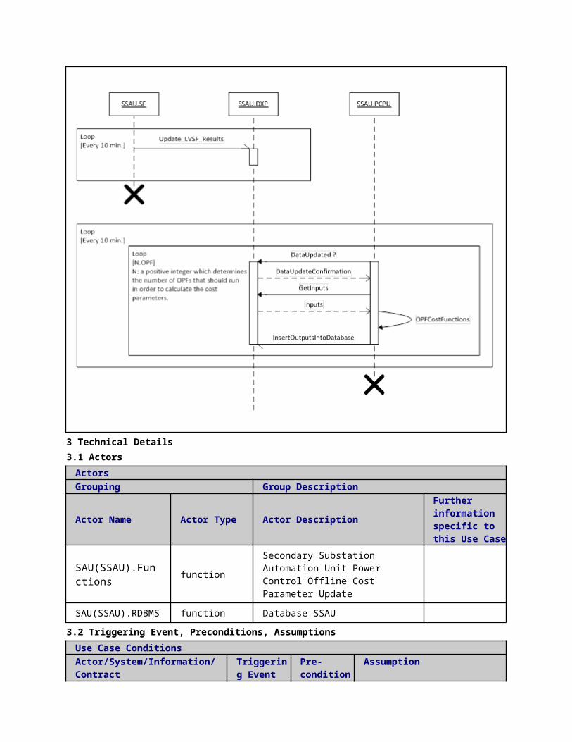

3 Technical Details3.1 Actors
ActorsGrouping Group Description
Actor Name Actor Type Actor DescriptionFurther information specific to this Use Case
DMS.functions
function
Distribution System Operator - Technical Aggregator (DSO. Technical aggregator)
according to the Article 2.6 of the Directive: "a natural or legal person responsible for operating, ensuring the maintenance of and, if necessary, developing the distribution system in a given area and, where applicable, its interconnections with other systems and for ensuring the long-term ability of the system to meet reasonable demands for the distribution of electricity". Moreover, the DSO is responsible for regional grid access and grid stability, integration of renewables at the distribution level and regional load balancing.
TSOEMS
function
Transmission system energy management systemaccording to the Article 2.4 of the Electricity Directive 2009/72/EC (Directive): "a natural or legal person responsible for operating, ensuring the maintenance of and, if necessary, developing the transmission system in a given area and, where applicable, its interconnections with other systems, and for ensuring the long-term ability of the system to meet reasonable demands for the transmission of electricity". Moreover, the TSO is responsible for connection of all grid users at the transmission level and connection of the DSOs within the TSO control area.
CA.functions function The commercial aggregator offers services to aggregate energy production from different sources (generators) and acts towards the grid as one entity, including local aggregation of demand (Demand Response management) and supply (generation management). In cases
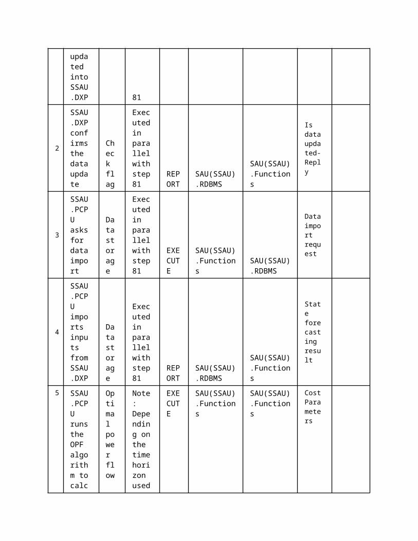
where the aggregator is not a supplier, it maintains a contract with the supplier.
DMS.WS function DMS web service interface
CA.WS function commercial aggregator web service interface
3.2 Triggering Event, Preconditions, AssumptionsUse Case ConditionsActor/System/Information/Contract
Triggering Event
Pre-conditions Assumption
3.3 ReferencesReferences
No. References Type Reference Statu
sImpact on Use Case
Organistaor / Organisation
Link
3.4 Further Information to the Use Case for Classification / MappingClassification InformationRelation to Other Use CasesOff-line Validation (OLV);Level of DepthDetatailed Use CAsePriorisationGeneric, Regional or National RelationNational RelationViewpointTechnicalFurther Keyword for ClassificationOff-line Validation, CRP, SRP, DSO
4 Step by Step Analysis of Use Case4.1 Overview of Scenarios
Scenario ConditionsNo.
Scenario Name Primary Actor Triggering Event Pre-Condition Post-Condition
4.2 Steps - ScenariosScenarioScenario Name: No. 1 - Bid Acceptance
Step No.
Event.
Name of Process/ Activity
Description of Process/ Activity.
Service
Information Producer (Actor)
Information Receiver (Actor)
Information Exchanged
Requirements, R-ID
1 Validation
Validation request
The bids to be validated are sent to
EXECUTE
CA.functions
CA.WS Request for CRP Activation

the DSO.Technical aggregator
2
Validation
Validation request
The bids to be validated are sent to the DSO.Technical aggregator
EXECUTE CA.WS DMS.WS
Request for CRP Activation
3 Corrective actions and Validation by the DSO.Technical aggregator
Power flow
The DSO.Technical aggregator accepts the bids or applies corrective actions and then sents the bids for validation by the TSO
EXECUTE
DMS.WS
DMS.functions
Request for Validation (by TSO)
4
Forwarding plan to TSO
Data report
The validation results of the TSO are sent to the DSO.Technical aggregator
EXECUTE
DMS.WS TSOEMS
Response of TSO
5 Response by the TSO
Power flow
The validation results
EXECUTE
TSOEMS
DMS.WS Response of TSO
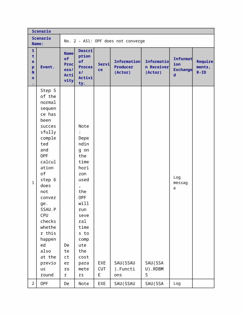
of the TSO are sent to the DSO.Technical aggregator
6
Modification Reply
Validation reply
The combined validation results are sent to the CA
EXECUTE
DMS.WS CA.WS
Bid Acceptance or Modification
ScenarioScenario Name: No. 2 - Bid Modification
Step No.
Event.
Name of Process/ Activity
Description of Process/ Activity.
Service
Information Producer (Actor)
Information Receiver (Actor)
Information Exchanged
Requirements, R-ID
1 Validation
Validation Request
The bids to be validated are sent to the DSO.Technical aggregator
EXECUTE
CA.WS DMS.WS
validation request
2
Validation
Power flow
The bids to be validated are sent to the DSO.Technical aggregator
EXECUTE
DMS.WS
DMS.functions
Request for CRP Activation
3 Corrective actions and Validati
Data report
The DSO.Technical aggregator
EXECUTE
DMS.WS
TSOEMS Request for Validation (by TSO)
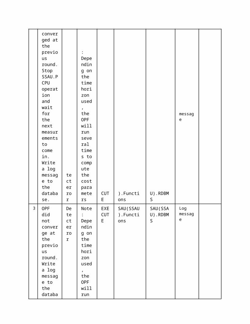
on by the TSO
accepts the bids or applies corrective actions and then sents the bids for validation by the TSO
4
Response by the TSO
Validation reply
The validation results of the TSO are sent to the DSO.Technical aggregator
EXECUTE
TSOEMS DMS.WS
Response of TSO
5Modification Reply
Validation reply
The combined validation results are sent to the CA
EXECUTE
DMS.WS CA.WS
Bid Acceptance or Modification
5 Information ExchangedInformation ExchangedName of Information (ID)
Description of Information Exchanged Requirements to information data
Request for CRP Activation
The Commercial Aggregator sends a signal to the DSO-TA to request the validation of a CRP to be activated.They are sent through internet services. It contains power to be activated, load area, time
Request for Validation (by TSO)
The DSO.Technical aggregator sends the bids (CRPs or SRPs) to be validated by the TSO
Response of TSO
The TSO sends his response, either accepting or curtailing the bids
Bid Acceptance or Modification
In case the bids can not be validated, due to network constraints violation, a modification is requested, else they
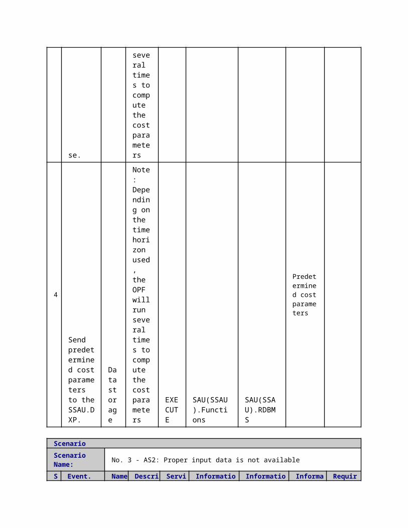
are accepted.It contains a curtailment factor. So that the commercial aggregator can apply that CRP with a certain Delta P
1 Description of the Use Case1.1 Name of the Use Case
Use Case Identification
IDArea / Domain(s)/Zone(s)
Name of the Use Case
183 Off-line Validation (OLV)
1.2 Version ManagementVersion Management
1.3 Scope and Objectives of Use CaseScope and Objectives of Use Case
ScopeThis use case shows the interaction between the CAs and the DSO.Technical aggregators, and the DSO.Technical aggregators and the TSO, required to validate technical feasibility of the bids resulting from the market clearing process
Objective(s) Validation of the CA's day-ahead and intra-day market bidding
Related businesscase(s)
1.4 Narrative of Use CaseNarrative of Use CaseShort descriptionUsed for Day-Ahead, Intra-day Market Validation. Validation in fixed steps (15 minutes steps) rather than over the whole day-ahead period. If flexibility products are not feasible during a time slot, they will be curtailed with disregard of the results for another time slot .Complete description
1. AD ProductsAll the Demand Response (DR) products by the different CAs, which have to be validated in the same Load Area (LA), are aggregated. The DR products validated can be:
SRPs Already activated CRPs (the re-profiling is obligatory for the activated CRPs) The CRPs that may or may not be activated in intraday market should be validated
afterwards. The SRPs and the already activated CRPs are prioritized.
2. Sequence Description:The OLV is used by both the DSO.Technical aggregator and the TSO. The procedure that is followed is:
First, the MO submits the bids to be Validated by the DSO.Technical aggregator The DSO.Technical aggregator aggregates the bids per Load Area and validates
them. If needed, a curtailment factor is applied The DR products are aggregated per Macro Load Area (MLA) and sent to the TSO. The validation procedure is repeated by the TSO A final validation or curtailment factor is applied, by combining the response of both
the DSO.Technical aggregator and the TSO. The results are sent to the MO

3. Time FrameThis process is applied right after the day-ahead market gate. The validation algorithm is run for timeslots of 15 minutes. This means that the validation is not executed for the whole day-ahead period, but for every 15 min. time slot independently.
4. OLV AlgorithmThe submitted bids (DR Products), as well as the forecasted state of the network (Loads, Generation, Topology), are the inputs of the OLV algorithm. Then, the System Operator runs a Power Flow and/or an Optimal Power Flow, in order to check for any limit violation in the network. If no violations are calculated the DR products are accepted, else they are curtailed or rejected.The steps of the algorithm are:
During the day ahead, the base load/generation of the network, without the activation of the DR, is forecasted, along with the plans for the network topology for the day after.
The DR products to be validated are sent by the CAs to the DSO.Technical aggregator . They are aggregatedper load area and added to the bus data
A Power Flow is executed by the DSO.Technical aggregator , to check the voltage, branch loading and power capabilities constraints of the network.
If from DSO.Technical aggregator's point of view, the requirement is not accepted, DSO.Technical aggregator performs an Optimal Power Flow in order to find the minimum amount of DR that should be curtailedIt is Formulated as single period MINL Optimal Power Flow:
Objective function: Minimise flexibility products curtailment Equalities: Power flow in each node Inequalities:
Voltage constraints Branch capacity constraints Power generation capabilities of flexible injection model that can be
used for both DG and DR Next, the TSO must validate and verify this DR service. In order to carry out this step,
DSO.Technical aggregator aggregates the (possibly already curtailed) product per Macro Load Area and sends the request to TSO for validation, using the same procedure
The final reply is sent to the CAs
1.5 General RemarksGeneral Remarks
2 Diagrams of Use Case
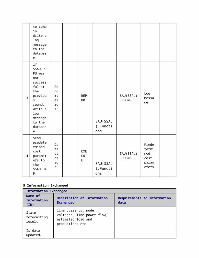

3 Technical Details3.1 Actors
ActorsGrouping Group Description
Actor Name Actor Type Actor DescriptionFurther information specific to this Use Case
DMS.functions
Function
Distribution System Operator - Technical Aggregator (DSO. Technical aggregator)
according to the Article 2.6 of the Directive: "a natural or legal person responsible for operating, ensuring the maintenance of and, if necessary, developing the distribution system in a given area and, where applicable, its interconnections with other systems and for ensuring the long-term ability of the system to meet reasonable demands for the distribution of electricity". Moreover, the DSO is responsible for regional grid access and grid stability, integration of renewables at the distribution level and regional load balancing.
DMS.WS function DMS, Web service interface
TSOEMS
function
according to the Article 2.4 of the Electricity Directive 2009/72/EC (Directive): "a natural or legal person responsible for operating, ensuring the maintenance of and, if necessary, developing the transmission system in a given area and, where applicable, its interconnections with other systems, and for ensuring the long-term ability of the system to meet reasonable demands for the transmission of electricity". Moreover, the TSO is responsible for connection of all grid users at the transmission level and connection of the DSOs within the TSO control area.
MOP function The unique power exchange of trades for the actual delivery of energy that receives the bids from the Balance Responsible Parties that have a contract to bid. The market operator determines the market energy price for the market balance area after applying technical constraints from

the system operator. It may also establish the price for the reconciliation within a metering grid area.
3.2 Triggering Event, Preconditions, AssumptionsUse Case ConditionsActor/System/Information/Contract
Triggering Event
Pre-conditions Assumption
3.3 ReferencesReferences
No. References Type Reference Statu
sImpact on Use Case
Organistaor / Organisation
Link
3.4 Further Information to the Use Case for Classification / MappingClassification InformationRelation to Other Use CasesLevel of DepthDetailed Use CasePriorisationGeneric, Regional or National RelationNational RelationViewpointTechnicalFurther Keyword for ClassificationDSO.Technical aggregator, TSO, Validation, Bids
4 Step by Step Analysis of Use Case4.1 Overview of Scenarios
Scenario ConditionsNo.
Scenario Name Primary Actor Triggering Event Pre-Condition Post-Condition
4.2 Steps - ScenariosScenarioScenario Name: No. 1 - Bid Acceptance
Step No.
Event.Name of Process/ Activity
Description of Process/ Activity.
Service
Information Producer (Actor)
Information Receiver (Actor)
Information Exchanged
Requirements, R-ID
1Validation from MO to DMS.TA
Validation request
The bids to be validated are sent to the DSO.Technical aggregator
EXECUTE MOP DMS.WS
Request for bid Validation (by DSO.Technical aggregator)
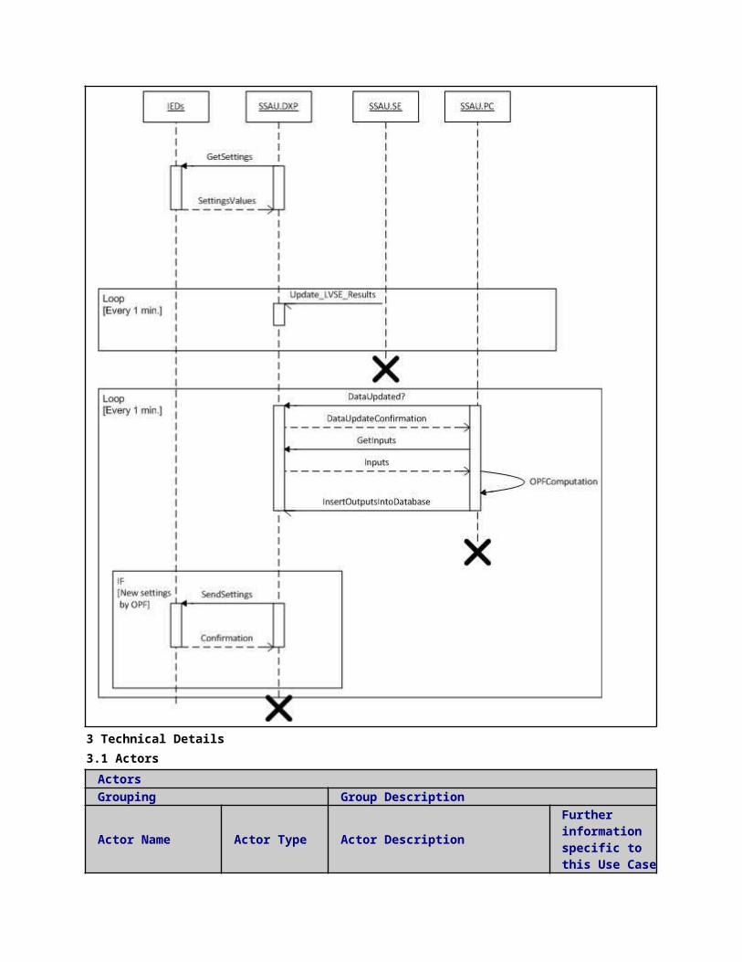
2Validation by the DMS.TA
Power flow
The DSO.Technical aggregator sents the bids for validation by the TSO
EXECUTE
DMS.WS
DMS.functions
Request for Validation (by TSO)
3
Response of the TSO
Data report
The validation results of the TSO are sent to the DSO.Technical aggregator
EXECUTE
DMS.WS TSO
Bid Acceptance or Modification
Response of the TSO
Validation reply
The validation results of the TSO are sent to the DSO.Technical aggregator
EXECUTE TSO DMS.WS
Bid Acceptance or Modification
4
Validation
Validation reply
The combined validation results are sent to the MO
EXECUTE
DMS.WS MOP
Bid Acceptance or Modification
ScenarioScenario Name: No. 2 - Bid Modification
Step No
Event. Name of Process/
Description of Process/
Service Information Produce
Information Receive
Information Exchanged
Requirements, R-ID
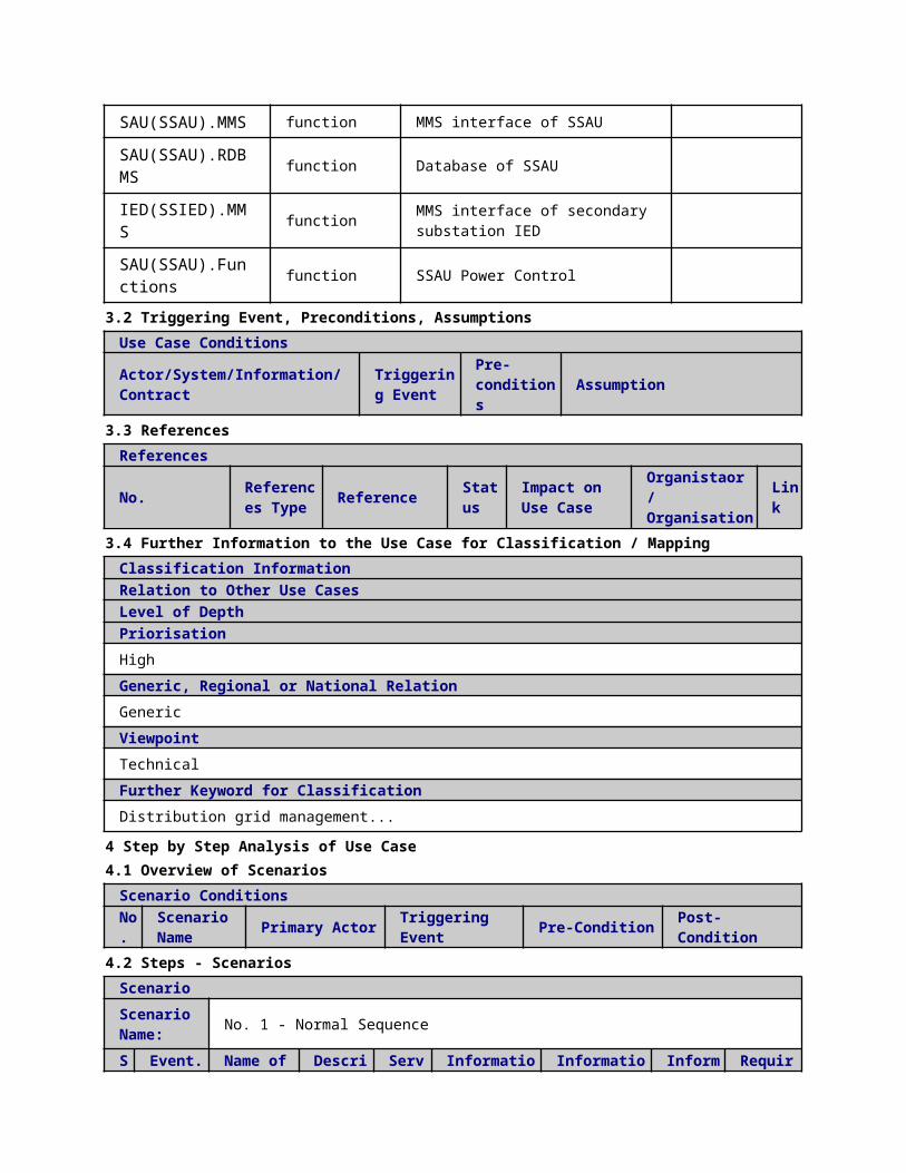
. Activity Activity. r (Actor) r (Actor)
1
Validation
Validation request
The bids to be validated are sent to the DSO.Technical aggregator
EXECUTE MOP
DMS.WS
Request for bid Validation (by DSO.Technical aggregator)
2
Curtailment and validation by the TSO
Power flow
The bid are curtailed by the DSO.Technical aggregator to comply with the network constraints. Then they are sent to the TSO to be validated.
EXECUTE
DMS.WS TSO
Request for Validation (by TSO)
3
Validation or modification by the TSO
Power flow
The validation results of the TSO (acceptance or modification) are sent to the DSO.Technical aggregator
EXECUTE TSO
DMS.WS
Bid Acceptance or Modification
4 Validation
Validation reply
The combined validation results
EXECUTE
DMS.WS
MOP Bid Acceptance or Modification
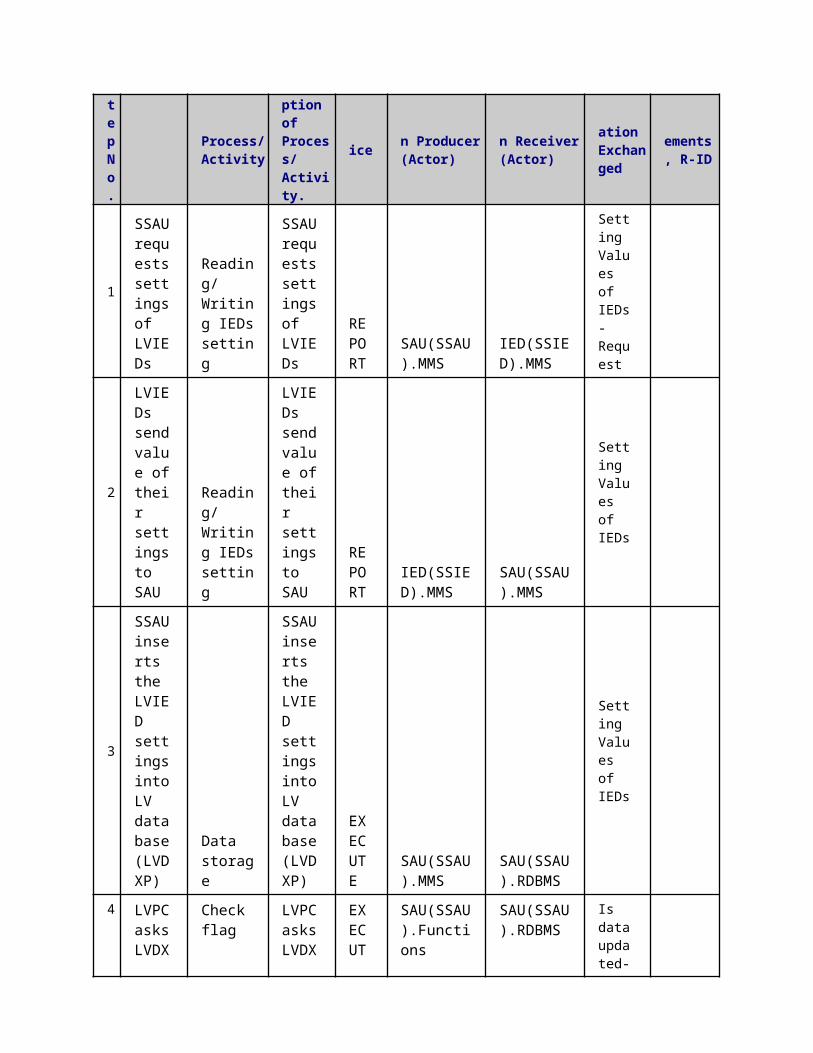
are sent to the Aggregator
5 Information ExchangedInformation ExchangedName of Information (ID)
Description of Information Exchanged Requirements to information data
Bid Acceptance or Modification
In case the bids can not be validated, due to network constraints violation, a modification is requested, else they are accepted.It contains a curtailment factor. So that the commercial aggregator can apply that CRP with a certain Delta P
Request for Validation (by TSO)
The DSO.Technical aggregator sends the bids (CRPs or SRPs) to be validated by the TSO
Request for bid Validation (by DSO.Technical aggregator)
The MO sends the bids (CRPs or SRPs) to be validated by the DSO.Technical aggregator
1 Description of the Use Case1.1 Name of the Use Case
Use Case Identification
IDArea / Domain(s)/Zone(s)
Name of the Use Case
151 Load Areas Configuration
1.2 Version ManagementVersion Management
1.3 Scope and Objectives of Use CaseScope and Objectives of Use Case
ScopeThis use case shows the interaction between the TSO and the DSO.Technical aggregators, and between the DSO.Technical aggregators and the CAs, required to assign the macro load areas/load areas/prosumers properly.
Objective(s) This configuration process would be performed for including new prosumers in the aggregation portfolio and should be updated periodically.
Related businesscase(s)
1.4 Narrative of Use CaseNarrative of Use CaseShort descriptionThe function of the load area is to group prosumers in terms of: consumption pattern, impedance value, prosumer connectivity, and other parameters to be considered by the

DSO.Technical aggregator .Complete descriptionSteps:
TSO assigns each (DSO.Technical aggregator s') load area to a macro load area and communicates this information to the DSO.Technical aggregator s.
The DSO.Technical aggregator assigns each prosumer to a load area and communicates this information to the CAs.
Assumption: DSO.Technical aggregator has the knowledge of which low voltage consumer is in the portfolio of each CA; this is done off-line and would not be part of this use case.
1.5 General RemarksGeneral Remarks
2 Diagrams of Use Case
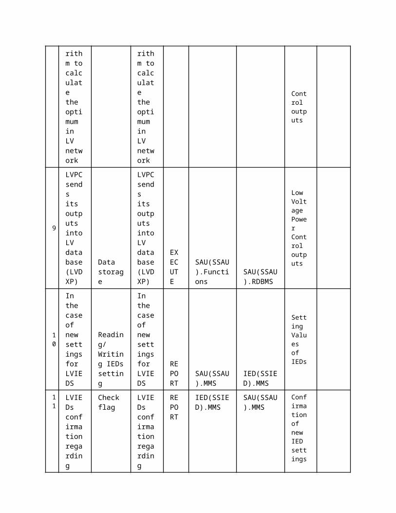
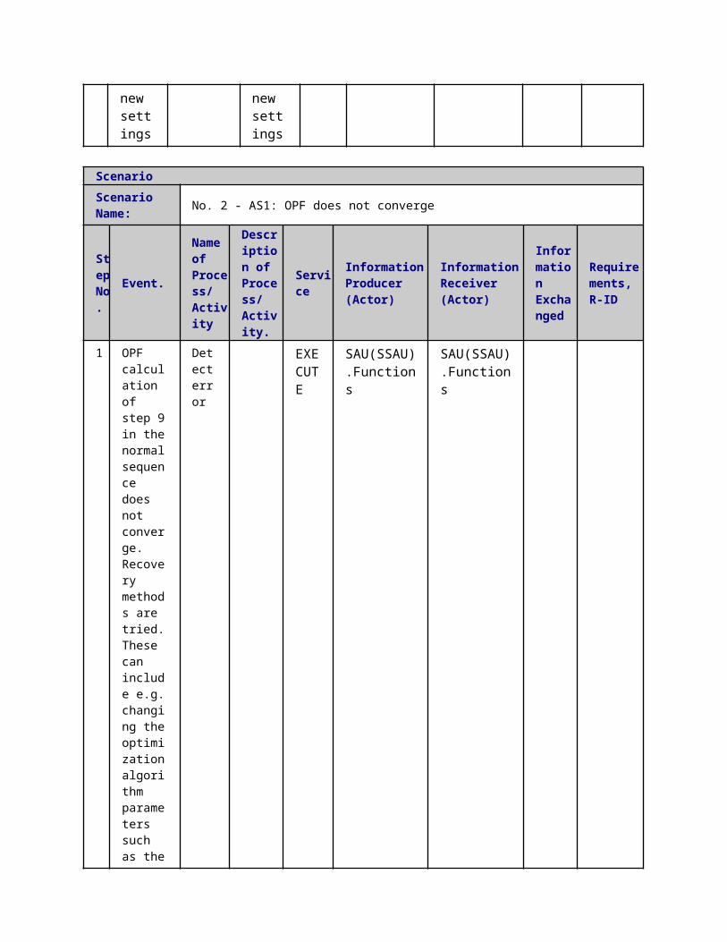
3 Technical Details3.1 Actors
ActorsGrouping Group Description
Actor Name Actor Type Actor DescriptionFurther information specific to this Use Case
TSOEMS
according to the Article 2.4 of the Electricity Directive 2009/72/EC (Directive): "a natural or legal person responsible for operating, ensuring the maintenance of and, if necessary, developing the transmission system in a given area and, where applicable, its interconnections with other systems, and for ensuring the long-term ability of the system to meet reasonable demands for the transmission of electricity". Moreover, the TSO is responsible for connection of all grid users at the transmission level and connection of the DSOs within the TSO control area.
DMS.functions
Distribution System Operator - Technical Aggregator (DSO. Technical aggregator)
according to the Article 2.6 of the Directive: "a natural or legal person responsible for operating, ensuring the maintenance of and, if necessary, developing the distribution system in a given area and, where applicable, its interconnections with other systems and for ensuring the long-term ability of the system to meet reasonable demands for the distribution of electricity". Moreover, the DSO is responsible for regional grid access and grid stability, integration of renewables at the distribution level and regional load balancing.
CA.WS The commercial aggregator offers services to aggregate energy production from different sources (generators) and acts towards the grid as one entity, including local aggregation of demand (Demand Response management) and supply (generation management). In cases where the aggregator is not a supplier, it maintains a contract with
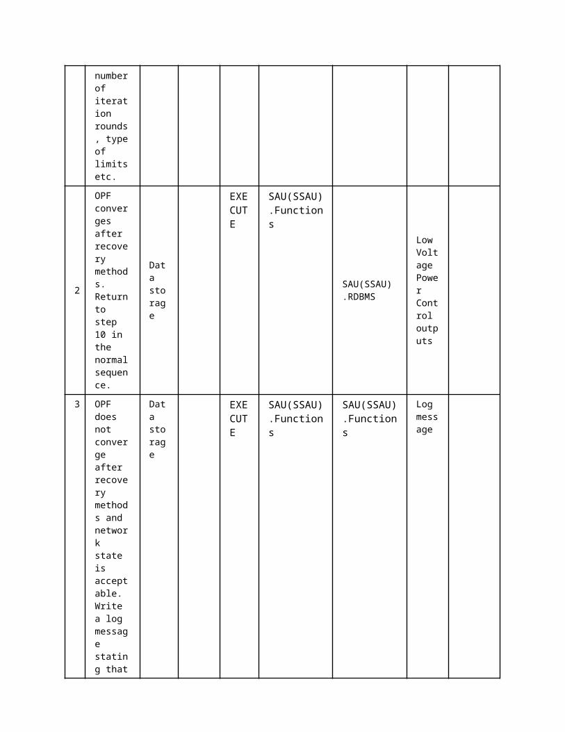
the supplier.
DMS.WS DMS, WS interface
DMS.RDBMS DMS Database
3.2 Triggering Event, Preconditions, AssumptionsUse Case ConditionsActor/System/Information/Contract
Triggering Event
Pre-conditions Assumption
3.3 ReferencesReferences
No. References Type Reference Statu
sImpact on Use Case
Organistaor / Organisation
Link
3.4 Further Information to the Use Case for Classification / MappingClassification InformationRelation to Other Use CasesLevel of DepthDetailed Use CasePriorisationGeneric, Regional or National RelationNational RelationViewpointTechnicalFurther Keyword for Classification
4 Step by Step Analysis of Use Case4.1 Overview of Scenarios
Scenario ConditionsNo.
Scenario Name Primary Actor Triggering Event Pre-Condition Post-Condition
4.2 Steps - ScenariosScenarioScenario Name: No. 1 - LA Configuration due to network changes
Step No.
Event.Name of Process/ Activity
Description of Process/ Activity.
Service
Information Producer (Actor)
Information Receiver (Actor)
Information Exchanged
Requirements, R-ID
1
Macro Load area configuration
Load area configuration
Assignment of LAs to MLAs
EXECUTE TSO TSO
Configuration of the Macro Load Areas
2 Macro Load area configur
Data report
Assignment of LAs to
EXECUTE
TSO DMS.WS Configuration of the Macro

ation MLAsLoad Areas
3
Macro Load area configuration
Data storage
Assignment of LAs to MLAs
EXECUTE DMS.WS
DMS.RDBMS
Configuration of the Macro Load Areas
4
Macro Load area configuration
Load area configuration
Assignment of LAs to MLAs
EXECUTE
DMS.RDBMS
DMS.functions
Configuration of the Macro Load Areas
5
Macro Load area configuration
Data storage
Assignment of LAs to MLAs
EXECUTE
DMS.functions
DMS.RDBMS
Configuration of the Macro Load Areas
5 Information ExchangedInformation ExchangedName of Information (ID)
Description of Information Exchanged Requirements to information data
Configuration of the Macro Load Areas
The Macro Load Area configuration is assigned
Configuration of the Load Areas
The Load Area configuration is assigned
1 Description of the Use Case1.1 Name of the Use Case
Use Case Identification
IDArea / Domain(s)/Zone(s)
Name of the Use Case
149 SRP Day-ahead and intra-day market procurement
1.2 Version ManagementVersion Management
1.3 Scope and Objectives of Use CaseScope and Objectives of Use CaseScope Market trading of SRP (Scheduling Re-Profiling) products for the day-ahead and
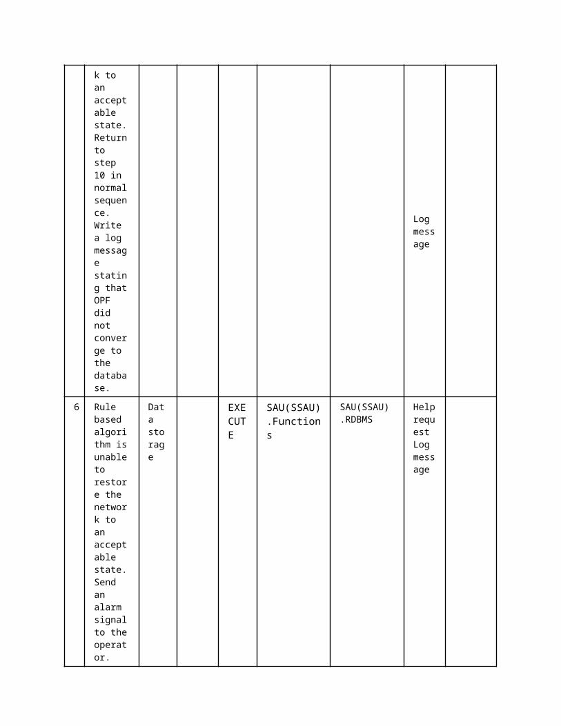
intra-day energy markets, where the CA will have the obligation to provide a specified demand modification (reduction or increase) at a given time to a flexibility buyer.
Objective(s) Day-ahead and intra-day market clearing for obtaining the set of accepted bids and the market clearing price.
Related businesscase(s)
1.4 Narrative of Use CaseNarrative of Use CaseShort descriptionThis use case shows the interaction of the flexibility buyers (BRPs) and suppliers (CAs) with the MO so as to enable market clearing for SRP products in the day-ahead and intra-day marketsComplete descriptionThe MO will send a bidding process creation message to flexibility providers/buyers before the gate opens for the day-ahead or intra-day market (SRP). In between gate opening and gate closure of the market, flexibility bids will be taken into consideration during the clearing phase.Flexibility buyers/providers will submit flexibility bids to be considered during the market clearing phase. These bids should be sent during the gate opening period. One message will be sent for each load area for which the service is required/offered.Finally the market will clear itself to work out the set of accepted bids and the market clearing price. This information will be published by the MO to inform the flexibility buyers/providers about the market clearing price and the bidding acceptance. For those accepted bids, the possible modifications on the accepted volume will be also communicated.
1.5 General RemarksGeneral Remarks
2 Diagrams of Use Case
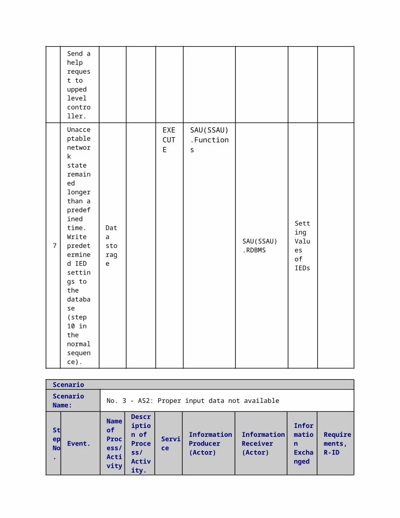
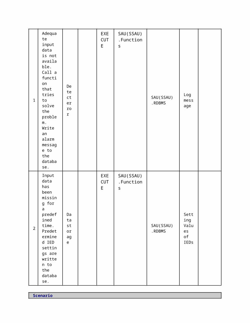
3 Technical Details3.1 Actors
ActorsGrouping Group Description
Actor Name Actor Type Actor DescriptionFurther information specific to this Use Case
CA.WS
roles
Offers services to aggregate energy production from different sources (generators) and acts towards the grid as one entity, including local aggregation of demand (Demand Response management) and supply (generation management). In cases where the CA is not a supplier, it maintains a contract with the supplier.
BRPP
function
A party that has a contract proving financial security and identifying balance responsibility with the imbalance settlement responsible of the market balance area entitling the party to operate in the market. This is the only role allowing a party to buy or sell energy on a wholesale level.
MOP
function
The unique power exchange of trades for the actual delivery of energy that receives the bids from the Balance Responsible Parties that have a contract to bid. The market operator determines the market energy price for the market balance area after applying technical constraints from the system operator. It may also establish the price for the reconciliation within a metering grid area.
DMS.WS
function
according to the Article 2.6 of the Directive: "a natural or legal person responsible for operating, ensuring the maintenance of and, if necessary, developing the distribution system in a given area and, where applicable, its interconnections with other systems and for ensuring the long-term ability of the system to meet reasonable demands for the distribution of electricity". Moreover, the DSO.Technical aggregator is responsible for regional grid access and grid stability, integration of renewables at the distribution level and regional load balancing.

3.2 Triggering Event, Preconditions, AssumptionsUse Case ConditionsActor/System/Information/Contract
Triggering Event
Pre-conditions Assumption
3.3 ReferencesReferences
No. References Type Reference Statu
sImpact on Use Case
Organistaor / Organisation
Link
3.4 Further Information to the Use Case for Classification / MappingClassification InformationRelation to Other Use CasesOff-line Validation (OLV);Level of DepthDetailed Use CasePriorisationGeneric, Regional or National RelationNational RelationViewpointBusinessFurther Keyword for ClassificationScheduled Re-Profiling, SRP, Market
4 Step by Step Analysis of Use Case4.1 Overview of Scenarios
Scenario ConditionsNo.
Scenario Name Primary Actor Triggering Event Pre-Condition Post-Condition
4.2 Steps - ScenariosScenarioScenario Name: No. 1 - SRP procured by BRP
Step No.
Event. Name of Process/ Activity
Description of Process/ Activity.
Service
Information Producer (Actor)
Information Receiver (Actor)
Information Exchanged
Requirements, R-ID
1Market Gate opening Market infos
The submission of offers and demand starts
EXECUTE MOP
CA.WS
Market Gate-opening signal
2 SRP submission from
Bid submission The SRPs are submi
EXECUTE
CA.WS
MOP Flexibility Offer

CA
tted to the market
3SRP demand from BRPs Bid submission
The demand of SRPs is submitted to the market by the BRP
EXECUTE BRPP MOP
Flexibility Demand
4
Market Gate Closure Market infos
The trading stops
EXECUTE MOP
CA.WS
Market Gate closure
5
off-line validation use case
off line validation
The trading is completed
EXECUTE MOP MOP
Bid Acceptance or Modification
6
Bid Validation
Bid acceptance/modification
If the SRP violates the network constraints, then it is modified, else it is accepted
EXECUTE MOP
CA.WS
Bid Acceptance or Modification
7 Bid Validation
Bid acceptance/modification
If the SRP violates the network constr
EXECUTE
MOP BRPP Bid Acceptance or Modification
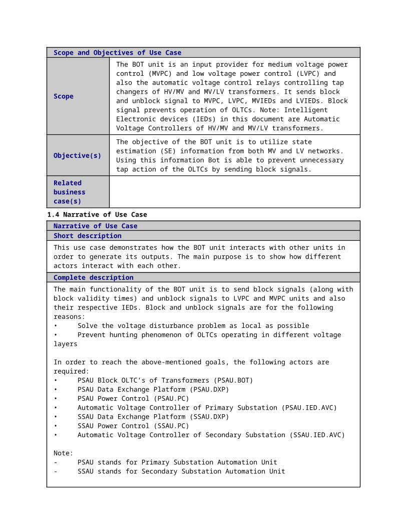
aints, then it is modified, else it is accepted
5Market clearance
Market clearance
The trading is completed
EXECUTE MOP MOP
Results Publishment
ScenarioScenario Name: No. 2 - SRP Procured by DSO.Technical aggregator
Step No.
Event. Name of Process/ Activity
Description of Process/ Activity.
Service
Information Producer (Actor)
Information Receiver (Actor)
Information Exchanged
Requirements, R-ID
1 Market Gate Opening Market infos
The submission of offers and demand starts
EXECUTE MOP
CA.WS
Market Gate-opening signal
2
SRP submission from CA Bid submission
The SRPs are submitted to the market
EXECUTE
CA.WS MOP
Flexibility Offer
3 SRP demand from DSO.TA
Bid submission The demand for SRPs is submitted to the market by the DSO.Technical
EXECUTE
DMS.WS
MOP Flexibility Demand

aggregator
4Market Gate Closure Market infos
The trading stops
EXECUTE MOP
CA.WS
Market Gate closure
5 Market clearance
Market clearance
The trading is completed
EXECUTE MOP MOP
Results Publishment
6 Off line validation UC
off line validation
The trading is completed
EXECUTE MOP MOP
Bid Acceptance or Modification
7
Bid modification submission
Bid acceptance/modification
The trading is completed
REPORT MOP
CA.WS
Bid Acceptance or Modification
8
Bid modification submission
Bid acceptance/modification
The trading is completed
REPORT MOP
DMS.WS
Bid Acceptance or Modification
5 Information ExchangedInformation ExchangedName of Information (ID)
Description of Information Exchanged Requirements to information data
Market Gate-opening signal
Used by the MO to inform about the opening of the market.
Flexibility Offer The CA submits the available offers of DR.
Flexibility Demand
The DR product buyers submit their demand for products
Market Gate closure
The MO informs about the market gate closure, i.e. the end of bid submission.
Results Publishment
The MO publishes the results of the market clearance, in order to inform the interested actors.
Bid Acceptance or Modification
In case the bids can not be validated, due to network constraints violation, a modification is requested, else they

are accepted.It contains a curtailment factor. So that the commercial aggregator can apply that CRP with a certain Delta P
1 Description of the Use Case1.1 Name of the Use Case
Use Case Identification
IDArea / Domain(s)/Zone(s)
Name of the Use Case
182 CRP Activation
1.2 Version ManagementVersion Management
1.3 Scope and Objectives of Use CaseScope and Objectives of Use Case
ScopeInteraction between the flexibility buyers and the CAs required to activate a CRP (conditional re-profiling) flexibility product. DSO.Technical aggregator technical validation is out of the scope of this use case.
Objective(s)To define the procedure for the activation of a CRP service (conditional re-profiling): The CA must have the capacity to provide a specified load profile modification (reduction or increase) during a given period. The delivery is called upon by the buyer of the flexibility product (similar to a reserve service).
Related businesscase(s)
1.4 Narrative of Use CaseNarrative of Use CaseShort descriptionThis use case shows the interaction between the flexibility buyers and the aggregators, required to activate a CRP (conditional re-profiling) flexibility product.Complete descriptionA flexibility buyer (DSO.Technical aggregator, TSO…) identifies the need to activate a previously settled CRP product for balancing and/or congestion management proposes.The flexibility buyer needs to send an explicit signal to the CA, telling that the CRP product needs to be activated.CRPs were previously validated by the Off-Line Validation (OLV). The DSO.Technical aggregator Real Time Validation (RTV) process has to approve the CRP activation request before its activation. Both validation processes are out of the scope of this use case and are further described in the RTV and OLV use cases.
1.5 General RemarksGeneral Remarks
2 Diagrams of Use Case

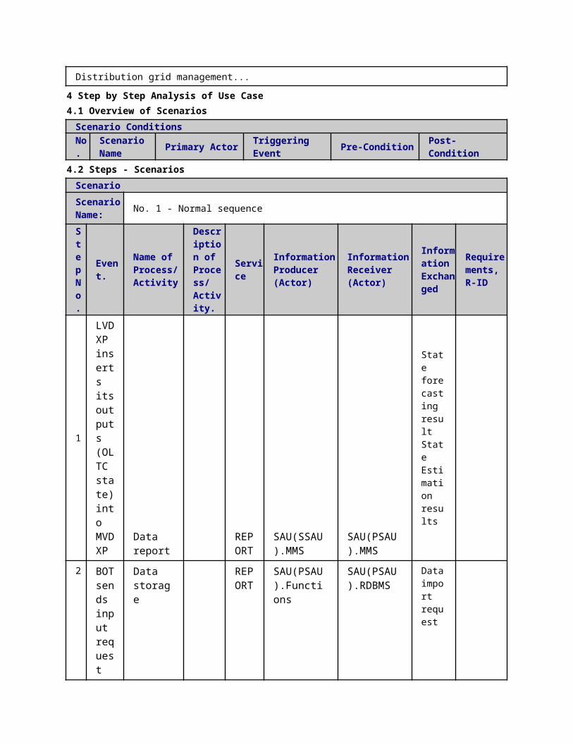
3 Technical Details3.1 Actors
ActorsGrouping Group Description
Actor Name Actor Type Actor DescriptionFurther information specific to this Use Case
CA.WS
roles
Offers services to aggregate energy production from different sources (generators) and acts towards the grid as one entity, including local aggregation of demand (Demand Response management) and supply (generation management). In cases where the CA is not a supplier, it maintains a contract with the supplier.
DMS.WS
roles
according to the Article 2.6 of the Directive: "a natural or legal person responsible for operating, ensuring the maintenance of and, if necessary, developing the distribution system in a given area and, where applicable, its interconnections with other systems and for ensuring the long-term ability of the system to meet reasonable demands for the distribution of electricity". Moreover, the DSO.Technical aggregator is responsible for regional grid access and grid stability, integration of renewables at the distribution level and regional load balancing.
BRPPRoles
Balance responsible party as potential buyer of a CRP, including the BRP, the retailer, the producer, etc.
IED(HEMS).WS function Home energy management system, WS interface
3.2 Triggering Event, Preconditions, AssumptionsUse Case ConditionsActor/System/Information/Contract
Triggering Event
Pre-conditions Assumption
3.3 ReferencesReferences
No. References Type Reference Statu
sImpact on Use Case
Organistaor / Organisation
Link
3.4 Further Information to the Use Case for Classification / MappingClassification InformationRelation to Other Use Cases
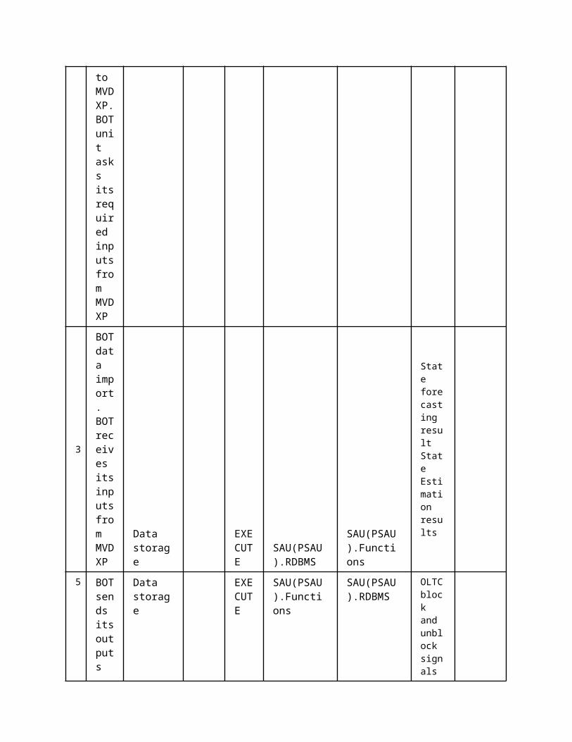
Real-Time Validation (RTV);Level of DepthDetailed Use CasePriorisationGeneric, Regional or National RelationNational RelationViewpointBusinessFurther Keyword for ClassificationConditional Re-profiling, CRP
4 Step by Step Analysis of Use Case4.1 Overview of Scenarios
Scenario ConditionsNo.
Scenario Name Primary Actor Triggering Event Pre-Condition Post-Condition
4.2 Steps - ScenariosScenarioScenario Name: No. 1 - CRP Activation
Step No.
Event.Name of Process/ Activity
Description of Process/ Activity.
Service
Information Producer (Actor)
Information Receiver (Actor)
Information Exchanged
Requirements, R-ID
1Activation signal
CRP activation request
The BRP request for a CRP to be activated by the CA
EXECUTE
BRPPDMS.WS CA.WS
CRP activation request
2
Validation request
Real time validation UC
The CRP must be validated by the DSO.Technical aggregator before it can be activated
EXECUTE
CA.WS CA.WS
validation results
3Activation of CRP
Data report
The CRP is activated by the CA
EXECUTE
CA.WS
BRPPDMS.WS
CRP Activation

4Activation of CRP
Reading/Writing IEDs setting
The CRP is activated by the CA
EXECUTE
CA.WS
IED(HEMS).WS
CRP Activation
ScenarioScenario Name: No. 2 - Modifed CRP activation
Step No.
Event.Name of Process/ Activity
Description of Process/ Activity.
Service
Information Producer (Actor)
Information Receiver (Actor)
Information Exchanged
Requirements, R-ID
1Activation Signal
CRP activation request
The BRP request for a CRP to be activated by the CA
EXECUTE
BRPPDMS.WS CA.WS
CRP activation request
2
Validation request
CRP Validation request
The CRP must be validated by the DSO.Technical aggregator before it can be activated
EXECUTE
CA.WS DMS.WS
validation results
3 Modification of the CRP before it is actvated
Real time validation UC
The corrective actions taken by the DSO.Technical aggregator are not enough. The CRP must be modified before
EXECUTE
DMS.WS
CA.WS Validation Results
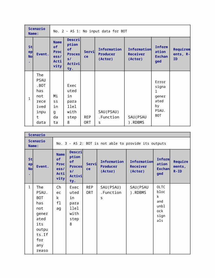
activated
4Activation
Reading/Writing IEDs setting
The CRP is activated by the CA
EXECUTE
CA.WS
IED(HEMS).WS
CRP Activation
ScenarioScenario Name: No. 3 - CRP Activation by the DSO.Technical aggregator
Step No.
Event.Name of Process/ Activity
Description of Process/ Activity.
Service
Information Producer (Actor)
Information Receiver (Actor)
Information Exchanged
Requirements, R-ID
1
Activation Signal
CRP activation request
The BRP request for a CRP to be activated by the Aggregator
EXECUTE
DMS.WS CA.WS
CRP Activation Request
2
Activation
Data report
The CRP is activated by the Aggregator
EXECUTE
CA.WS DMS.WS
CRP Activation
3
Activation
Reading/Writing IEDs setting
The CRP is activated by the Aggregator
EXECUTE
CA.WS
IED(HEMS).WS
CRP Activation
5 Information ExchangedInformation ExchangedName of Information (ID)
Description of Information Exchanged Requirements to information data
CRP Activation The activation of the CRP is

announced to the procurer of the CRP
CRP Activation Request
The buyer of the CRP request its activation by the CA
CRP ValidationThe CA asks the DSO.Technical aggregator to validate the activation of the CRP
Validation Results
The results of the DSO.Technical aggregator's validation are sent to the CA and the CRPs are activated or curtailed.
6 Requirements (optional)Requirements (optional)
7 Common Terms and DefinitionsCommon Terms and DefinitionsTerm Definition
8 Custom Information (optional)Custom Information (optional)Key Value Refers to Section
1 Description of the Use Case1.1 Name of the Use Case
Use Case Identification
IDArea / Domain(s)/Zone(s)
Name of the Use Case
153 Day-ahead demand response of the flexible demand
1.2 Version ManagementVersion Management
1.3 Scope and Objectives of Use CaseScope and Objectives of Use Case
ScopeDemand response is mainly a response to prices; therefore, there must be a concrete market structure to support the demand response. The spot market (or day-ahead market) and the day-ahead dynamic tariff (DT) are used as the market structure for defining demand response.
Objective(s)
The objective of the demand response is to generate a flexible demand schedule of a predefined time horizon, e. g. the next operation day (24 hours). The demand response defined in this use case is to fulfill the requirements of WP5 and the demand response in general can have much broader implication. The other functions, such as Forecasting in task 5.1 and Power Flow Control in task 5.2, can use the results of the demand response.
Related businesscase(s)
1.4 Narrative of Use CaseNarrative of Use CaseShort description
The day-ahead demand response function runs at the distribution network operator (DNO) side for the purpose of both demand forecast and congestion management. It receives input data, such as system price forecast, dynamic tariff (DT), weather forecast (temperature), EV driving pattern forecast, (driving distances, arriving or leaving times), and consumer requirements on house temperature from the data exchange platform (DXP). Then a least cost demand plan will be determined and sent back to DXP.Complete descriptionThe demand response function is performed before the clear of the day-ahead market because after the clear, the demand plan shall be determined and the aggregators or retailers should stick to their plan as much as possible. The DNO will use an optimization method to find a flexible demand plan that minimizes the total cost of the demands over a time horizon (e.g. 24 hours). Since it is assumed that the aggregators economically plan their demands, the demand plan determined by the DNO is a good estimation of the summation of the aggregators’ demand plans. Therefore, the demand response function can output this demand plan as the final result.The steps of the demand response function are as follows:
1. Obtain the input data including system prices, DT, weather forecast, EV driving pattern forecast and customer house temperature requirements for the demand response function, which is provided by other actors directly or through the DXP
2. run the optimization model, where the energy demands, comfort requirements of the customers and the availability of the flexible demands are included as constraints and the cost is the objective function.
3. the optimal demand plan found in step 2 will be sent to the DXP or other actors
1.5 General RemarksGeneral Remarks
2 Diagrams of Use Case
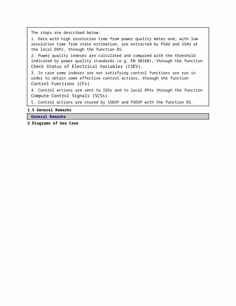
3 Technical Details3.1 Actors
ActorsGrouping Group Description
Actor Name Actor Type Actor DescriptionFurther information specific to this Use Case
3.2 Triggering Event, Preconditions, AssumptionsUse Case ConditionsActor/System/Information/Contract
Triggering Event
Pre-conditions Assumption
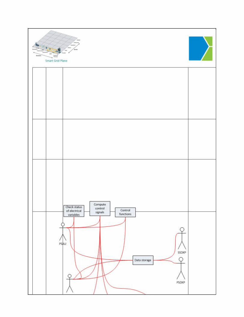
3.3 ReferencesReferences
No. References Type Reference Statu
sImpact on Use Case
Organistaor / Organisation
Link
3.4 Further Information to the Use Case for Classification / MappingClassification InformationRelation to Other Use CasesLevel of DepthPriorisationGeneric, Regional or National RelationViewpointFurther Keyword for Classification
4 Step by Step Analysis of Use Case4.1 Overview of Scenarios
Scenario ConditionsNo.
Scenario Name Primary Actor Triggering Event Pre-Condition Post-Condition
4.2 Steps - ScenariosScenarioScenario Name: No. 1 - Primary usecase
Step No.
Event.
Name of Process/ Activity
Description of Process/ Activity.
Service
Information Producer (Actor)
Information Receiver (Actor)
Information Exchanged
Requirements, R-ID
1
DADT algorithm starts. The CCPC starts the DADT algorithm
Check flags
The CCPC starts the DADT algorithm
REPORT
DMS.CCPC
DMS.DADT
start command
3 DADT algorithm collects data. The DADT algorithm receives the
Data Storage
The DADT algorithm receives the grid topology infor
REPORT
DMS.DXP.RDBMS
DMS.DADT
Grid model and network topology Historical system price
Forecasted Conventional/inflexible demand information Forecasted

grid topology information, the predicted demand and production and the grid model
mation, the predicted demand and production and the grid model
production information of DER
5
Exporting results of DADT. The DADT algorithm report the status of the algorithm and the final DT to DXP
Data Storage
The DADT algorithm report the status of the algorithm and the final DT to DXP
REPORT
DMS.DXP.RDBMS
DMS.CCPC
Algorithm status Grid tariff Energy plan Maximum overloading percentage
4 DADT algorithm running. Optimal power flow with grid model and predicted flexible and not-
Day ahead dynamic tariff calculation
EXECUTE
DMS.DADT
DMS.DXP.RDBMS
Algorithm status Grid tariff Energy plan Maximum overloading percentage

flexible demand and local production.
5 Information ExchangedInformation ExchangedName of Information (ID)
Description of Information Exchanged Requirements to information data
Grid tariff
Energy plan
Forecasted energy price
Environment temperature
1 Description of the Use Case1.1 Name of the Use Case
Use Case Identification
IDArea / Domain(s)/Zone(s)
Name of the Use Case
155 Day-Ahead Dynamic Tariff for Medium Voltage Grid Congestion Management - Based on predicted demand and local production
1.2 Version ManagementVersion Management
1.3 Scope and Objectives of Use CaseScope and Objectives of Use CaseScope
Objective(s)The objective of DADT2 is to determine a day-ahead dynamic tariff (DADT) to alleviate potential congestion induced by the demand or local production based on the predicted demand and local production.
Related businesscase(s)
1.4 Narrative of Use CaseNarrative of Use CaseShort descriptionThe day-ahead dynamic tariff algorithm based on the predicted demand and local production (DADT2) is to determine a day-ahead tariff for the distribution network to alleviate potential congestion induced by the demand or local production. The congestion in this context is the component overloading. The input data are the customer day-ahead energy plan and local
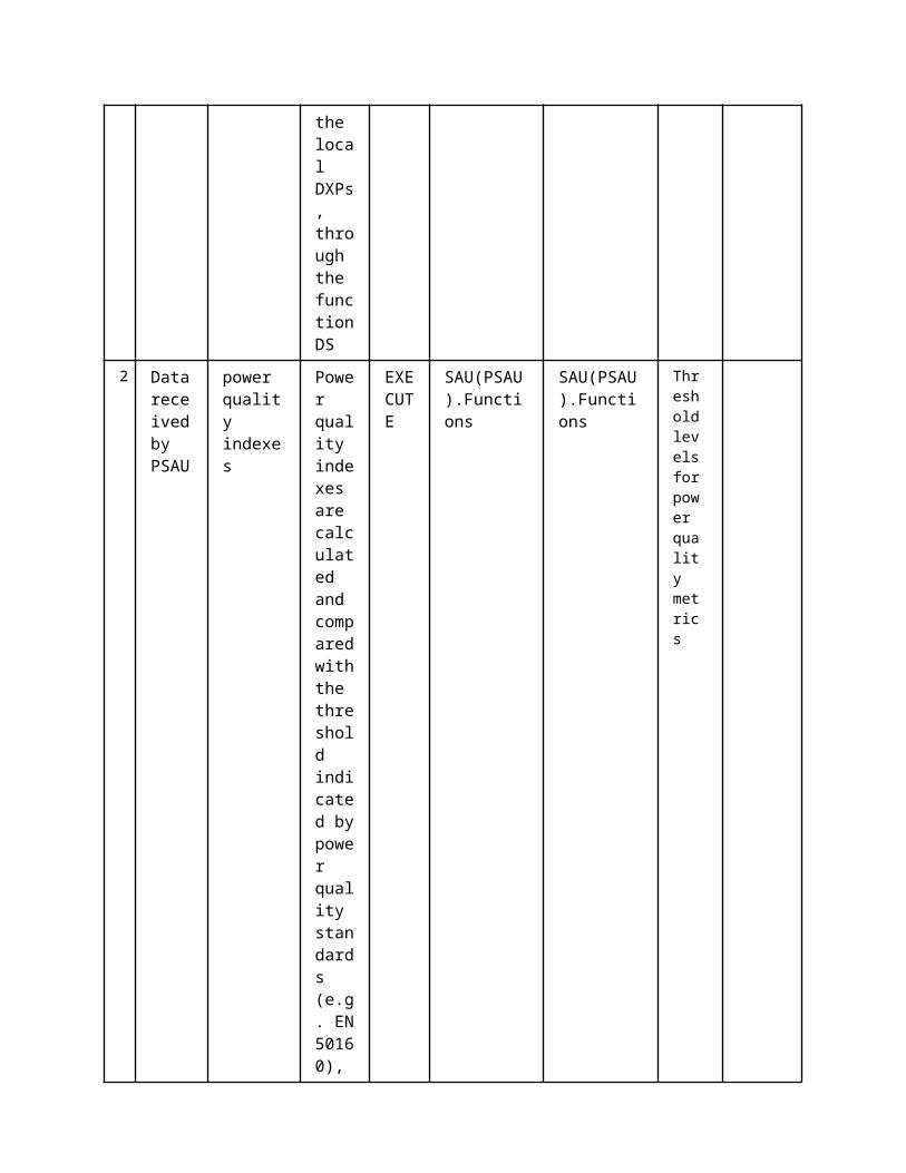
production forecast, the grid topology and the grid model.Complete descriptionThe Day-Ahead Dynamic Tariff for medium voltage grid congestion management - based on the predicted demand and local production (DADT2) will be developed to alleviate the congestion in the day-ahead time frame. The congestion is defined as the overloading issue in the dynamic tariff concept work. The DNO receives the predicted day-ahead demand and local production from the forecaster, the grid model and the grid topology from the control center network power control as inputs. The DNO runs time series power flow to check if there is any overloading in the distribution network. If there is congestion, the DNO will determine the day-ahead dynamic tariff to influence the flexible demands by putting an extra cost of electricity consumption. The determination of the grid tariff can be done in different manners, i.e. use capacity allocation algorithm to alleviate congestion, use a market clearing process for the day-ahead DSO market with two options – buy flexibility from aggregators or locational prices.
Steps in the DADT1 are as follows:1. The forecaster at the DNO side predicts the demand and the local production within the distribution network2. The control room network power control determines the optimal grid topology according to the predicted demand and the local production within the distribution network3. The DADT algorithm receives the grid topology information, the predicted demand and production and the grid model to check if there is any congestion.4. The DADT algorithm determines the day-ahead tariffs for the distribution network to alleviate congestion; The tariff calculation can be done in ways.
1.5 General RemarksGeneral Remarks
2 Diagrams of Use Case

3 Technical Details3.1 Actors
ActorsGrouping Group Description
Actor Name Actor Type Actor DescriptionFurther information specific to this Use Case
DMS.functions Function DMS demand response algorithm
SPP Function Service provide platform
DMS.WS Function DMS, WS interface

CA.WS Function CA , WS interface
CA.functionsFunction Commercial aggregator, asset
planning functions
DMS.RDBMS Function DMS database
CA.RDBMS Function CA database
3.2 Triggering Event, Preconditions, AssumptionsUse Case ConditionsActor/System/Information/Contract
Triggering Event
Pre-conditions Assumption
3.3 ReferencesReferences
No. References Type Reference Statu
sImpact on Use Case
Organistaor / Organisation
Link
3.4 Further Information to the Use Case for Classification / MappingClassification InformationRelation to Other Use CasesLevel of DepthPriorisationGeneric, Regional or National RelationViewpointFurther Keyword for Classification
4 Step by Step Analysis of Use Case4.1 Overview of Scenarios
Scenario ConditionsNo.
Scenario Name Primary Actor Triggering Event Pre-Condition Post-Condition
4.2 Steps - ScenariosScenarioScenario Name: No. 1 - Primary scenario. Once per day
Step No.
Event.Name of Process/ Activity
Description of Process/ Activity.
Service
Information Producer (Actor)
Information Receiver (Actor)
Information Exchanged
Requirements, R-ID
1 DADT algorithm initiates the DT calculation. DADT algorithm initiates the
Check flag
DADT algorithm initiates the algorithm by sending initial DT to DXP
EXECUTE
DMS.functions
DMS.RDBMS
Grid tariff
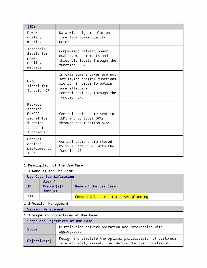
algorithm by sending initial DT to DXP
2
The DR algorithm receives necessary data. The aggregator receives the predicted day-ahead system price and weather forecast
Data storage
The aggregator receives the predicted day-ahead system price and weather forecast
EXECUTE SPP CA.WS
Forecasted energy priceEnvironment temperature
3
The aggregator receives DT.The aggregator receives DT from the DXP
Data Report
The aggregator receives DT from the DXP
EXECUTE DMS.WS CA.WS
Grid tariff
4
The aggregator receives DT.The aggregator receives DT from the DXP
Data Report
The aggregator receives DT from the DXP
EXECUTE CA.WS
CA.RDBMS
Grid tariff
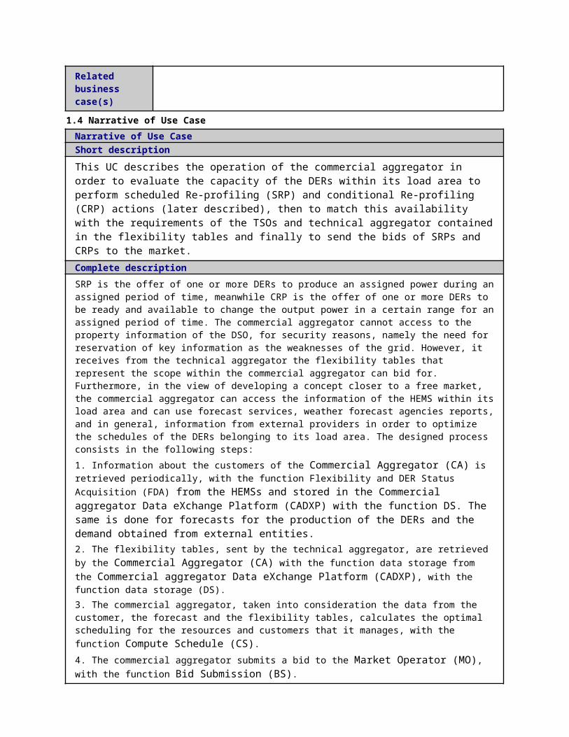
5
CA manages its resources with a certain dynamic tariff. Optimization of CA's resources
Commercial aggregator asset planning UC
The DADT algorithm receives the preliminary energy planning
EXECUTE
CA.functions
CA.RDBMS
Energy plan
6
Demand response. The aggregator sends the preliminary energy planning of flexible demands to the data exchange platform (DXP)
Data Report
The aggregator sends the preliminary energy planning of flexible demands to the data exchange platform (DXP)
EXECUTE CA.WS DMS.WS
Energy plan
7 Demand response. The aggregator sends the preliminary energy plannin
Data storage
The aggregator sends the preliminary energy planning of flexible
EXECUTE
DMS.WS DMS.RDBMS
Energy plan

g of flexible demands to the data exchange platform (DXP)
demands to the data exchange platform (DXP)
8
The DADT algorithm receives DRThe DADT algorithm receives the preliminary energy planning
Data storage
The DADT algorithm receives the preliminary energy planning
EXECUTE
DMS.RDBMS
DMS.functions
Energy plan
5 Information ExchangedInformation ExchangedName of Information (ID)
Description of Information Exchanged Requirements to information data
Grid model and network topology
Historical system price
Forecasted Conventional/inflexible demand information
Forecasted production information of DER
Environment temperature
Algorithm status
Grid tariff
Energy plan
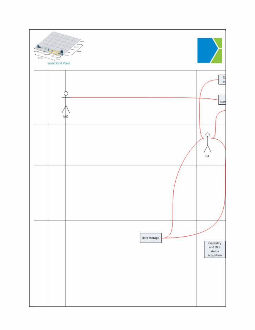
Maximum overloading percentage
start command