use & care guide and installation instructions · use & care guide and installation...
TRANSCRIPT
Monogram.
Use & Care Guide andInstallation Instructions
for ZDIB50ZDIW50
Automatic Icemaker
General Electric CompanyLouisville, KY40225
Monogram.":"
Automatic h:emaker
Pub. No. 49-6857
Parl No. 162D7745P002
] 2-95 C(;

Introduction
Your new Monogram icemaker makes an eloquentstatement of style, convenience and kitchen planningflexibility. Whether you chose it for its purity ofdesign, practical features or assiduous attention todetail--or for all of these reasons--you'll find thatyour Monogram icemaker's superior blend of formand function will delight you for years to come.
The Monogram icemaker was designed to providethe flexibility to blend in with your kitchen cabinetry.
The information on the following pages will helpyou operate and maintain your icemaker properly.
For a listing of dealers--or if you have otherquestions--please call the GE Answer Center _:(800.626.2000).
Contents
Appliance Registration ................. 3
Care and Cleaning .................. 7-10
Changing the Light Bulb ...... 10
Condenser .............................. 7
Filtering & Treating Water... 10
Icemaker System .................... 8
Inside Parts of the Icemaker...9
Outside Surfaces .................... 7
Consumer Services ..................... 20
Controls ........................................ 6
Features ......................................... 6
Installation Instructions ........ 16-18
Electrical Requirements ....... 16
Free Standing Installation .... 16
Grounding Instructions ........ 16
Model and Serial NumberLocation ............................. 3, 6
Operating Instructions .............. 5, 6
Preparation ............................ 1l- 15
Changing the Bin
Door Panel ........................ 12
Changing the Lower
Access Panel ..................... 13
Leveling ............................... 11
Location ............................... 11
Custom Door
and Access Panels ............. 14
Thermostat Calibrations ....... 11
Unpacking the Icemaker ...... 11
Vacation and Moving ........... 15
Problem Solver ........................... 19
Safety Instructions ........................ 4
Warranty ..................................... 21
Questions?Call GEAnswer Center800.626.2000
2

HELP US HELP YOU...
Read this guide carefully.
It is intended to help you operate and maintain yournew icemaker properly.
Keep it handy for answers to your questions.
If you don't understand something or needmore help, call:
GE Answer Center _"_800.626.2000
24 hours a day, 7 days a week
If you received a damaged icemaker...
Immediately contact the dealer (or builder) that soldyou the icemaker.
Save time and money.Before you request service...
Check the Problem Solver. It lists minor operatingproblems that you can correct yourself.
Write down the model and serial numbers.
You'll see them on a plate on the left side of the ice bin.
These numbers are also on the Consumer
Product Ownership Registration Card that camewith your icemaker.
Before sending in the registration card, please writethese numbers here:
Model Number
Serial Number
Use these model and serial numbers in any correspondenceor service calls concerning your icemaker.
IF YOU NEED SERVICE
To obtain service, see the Consumer Services page inthe back of this guide.
We're proud of our service and want you to bepleased. If for some reason you are not happy with theservice you receive, here are three steps to follow forfurther help.
FIRST, contact the people who serviced yourappliance. Explain why you are not pleased. In mostcases this will solve the problem.
NEXT, if you are still not pleased, write all thedetails--including your phone number--to:
Manager, Consumer RelationsGE AppliancesAppliance ParkLouisville, KY 40225
FINALLY, if your problem is still not resolved, write:
Maior Appliance Consumer Action Program20 North Wacker Drive
Chicago, IL 60606
3

IMPORTANT SAFETY INSTRUCTIONSRead All Instructions Before Using This Appliance.
_ ARNING--To reduce the risk of fire,electrical shock, or injury when usingyour icemaker, follow basic precautionsincluding the following:
• Never allow children to operate, play with, orcrawl inside the icemaker.
• Never clean icemaker parts with flammablefluids. The fumes can create a fire hazard orexplosion•
• For your safety: Do not store or use gasolineor other flammable vapors and liquids in thevicinity of this or any other appliance• Thefumes can create a fire hazard or explosion•
• Be sure your icemaker is properly installed andgrounded by a qualified technician inaccordance with the Installation Instructions•
• Do not attempt to repair or replace any part ofvour icemaker unless it is specificallyrecommended in this guide• All other servicingshould be referred to a qualified technician•
• It is your responsibility to be sure yourlcemaker:
n has been installed where it is protected fromthe elements.
-- is located so that the front is not blocked to
restrict incoming or discharge air flow.
-- is properly leveled.
is located in a well ventilated area with
temperatures above 55 °E (13°C.) and below110°E (43°C.). Best results are obtained at
temperatures between 70°F. (21°C.) and90°F. (32°C.).
is properly connected to a water supplyand drain.
is connected only to the proper kind of outlet,with the correct electric supioly and grounding.
A 120 volt. 60 Hz.. 15 amp fused electricalsupply is required. NOTE: Time delay fuse orcircuit breaker is recommended.
is not used by anyone unable to operateit properly.
-- is used only to do what icemakers aredesigned to do.
-- is properly maintained.
SAVE THESEINSTRUCTIONS

OPERATING YOUR ICEMAKER
How the Icemaker Works
1. Water is constantly circulated over a freezing plate.As the water freezes into ice, the minerals in thewater are reiected. This produces a sheet of ice witha low mineral content.
NOTE: The icemaker is designed to make clear icefrom the maiority of water sources on a daily basis.If your results are unsatisfactory, water may need tobe filtered or treated. See Filtering and TreatingWater in the Care and Cleaning section.
2. When the desired thickness is reached, the ice sheetis released and slides onto a cutter grid. The griddivides the sheet into individual cubes.
3. The water containing the reiected minerals isdrained after each freezing cycle.
4. Fresh water enters the machine for the next
icemaking cycle.
5. Cubes fall into the storage bin. When the bin is full,the icemaker shuts off automatically and restartswhen more ice is needed.
_:'" J
Notes About This Icemaker
• Water enters only during the defrost cycle. Thereforethe first cycle will be completed without water in thesystem.
• As the room and water temperatures vary, so willthe amount of ice produced. This means that higheroperating temperatures will result in reduced iceproduction.
• The icemaker will shut off when ice in the storagebin touches the bin thermostat well and will
automatically cycle to keep the bin full.
• The storage bin is not refrigerated and some meltagewill occur. This, too, varies with the room temperature.
• The icemaker needs good air circulation toperform efficiently. Keep the front grille andthe condenser clean.
• The water system, including the filter screen in thewater inlet solenoid valve, needs to be cleanedperiodically for good circulation. Instructions arelocated on the inner door panel.
(contimted next page)
5
OPERATING YOUR ICEMAKER(continued)
Setting the Controls
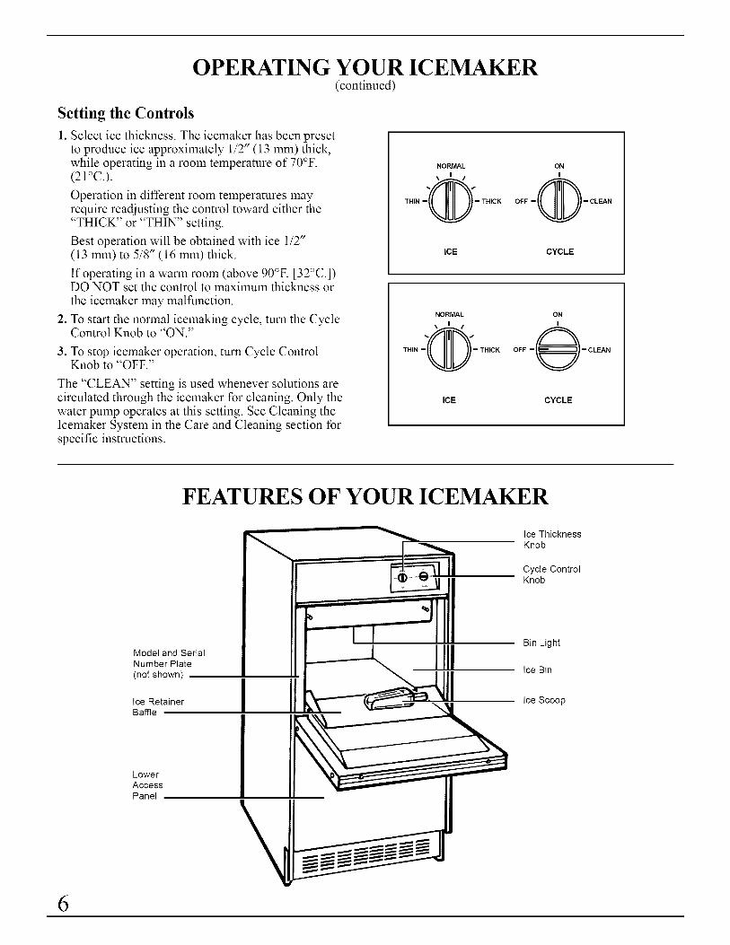
1. Select ice thickness. The icemaker has been presetto produce ice approximately 1/2" (13 mm) thick,while operating in a room temperature of 70°F.(21°C.).
Operation in different room temperatures mayrequire readjusting the control toward either the"THICK" or "TH1N" setting.
Best operation will be obtained with ice 1/2"(13 mm) to 5/8" (16 mm) thick.
If operating in a warm room (above 90°F. [32°C.])DO NOT set the control to maximum thickness or
the icemaker may malfunction.
2. To start the normal icemaking cycle, turn the CycleControl Knob to "ON."
3. To stop icemaker operation, turn Cycle ControlKnob to "OFF."
The "CLEAN" setting is used whenever solutions arecirculated through the icemaker for cleaning. Only thewater pump operates at this setting. See Cleaning theIcemaker System in the Care and Cleaning section forspecific instructions.
THIN
NORMAL
THICK
ONI
OFF -_- CLEAN
ICE CYCLE
NORMAL
\ I /
OTHIN - - THICK
ON
I
OFF - _ - CLEAN
ICE CYCLE
FEATURES OF YOUR ICEMAKER
Model and SerialNumber Plate
(not shown)
Ice RetainerBaffle
LowerAccessPanel
I IIIII
Ice ThicknessKnob
Cycle ControlKnob
Bin Light
Ice Bin
Ice Scoop
6
CARE AND CLEANING
Periodically inspect and clean the icemaker to keep itoperating at peak efficiency and to prevent prematurefailure of system components.
Both the icemaking system and the air-cooledcondenser need to be cleaned regularly.
The minerals reiected from the circulating waterduring the freezing cycle will eventually form a hardscaly deposit in the water system which prevents arapid release of the ice from the freezing plate.
Clean the ice and water system periodically to removemineral scale build-up. Frequency of cleaningdepends on water hardness. With hard water (15 to 20grains/gal.), cleaning may be required as frequently asevery six months.
A dirty or clogged condenser:
• prevents proper air flow.
• reduces icemaking capacity.
• causes higher than recommended operatingtemperatures which may lead to component failure.
Cleaning Outside Surfaces
Wash the outside enamel surfaces and gaskets with warm water and mildsoap or detergent. Rinse and dry. Regular use of a good householdappliance cleaner and wax will help protect the finish.
Do not use abrasive cleaners on enamel surfaces as they may scratchthe finish.
Cleaning the Condenser
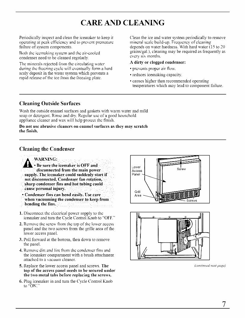
A _VARNING:• Be sure the icemaker is OFF and
disconnected from the main powersupply. The icemaker could suddenly start ifnot disconnected. Condenser fan rotation,sharp condenser fins and hot tubing couldcause personal injury.
o Condenser fins can bend easily. Use carewhen vacuuming the condenser to keep frombending the fins.
1. Disconnect the electrical power supply to theicemaker and turn the Cycle Control Knob to "OFF."
2. Remove the screw from the top of the lower accesspanel and the two screws from the grille area of thelower access panel.
3. Pull forward at the bottom, then down to removethe panel.
4. Remove dirt and lint from the condenser fins and
the icemaker compartment with a brush attachmentattached to a vacuum cleaner.
5. Replace the lower access panel and screws. Thetop of the access panel needs to be secured underthe two metal tabs before replacing the screws.
6. Plug icemaker in and turn the Cycle Control Knobto "ON."
GrillArea
Screws
(continued next page)
7

CARE AND CLEANING(continued)
Cleaning the Icemaker System
A WARNING: Most ice machine cleanersare citric or phosphoric acid which cancause irritation even after dilution. In
case of contact with eyes, flush eyes thoroughlywith fresh water and contact a physicianimmediately. In case of contact with skin, rinsewell with water. If swallowed, give largeamounts of water and contact a physicianimmediately. Do not induce vomiting. KEEPOUT OF REACH OF CHILDREN.
THI_- CLEAN
/
. Turn the Cycle Control Knob to "OFF."
/Harness I.". I.I
"Screws (long) "_
2. Remove the two screws and slide the ice cutter gridforward, out of the two slots near the water pan.
3. Unplug the electrical harness.
CAUTION:Any ice on the grid should bemelted under running warm water. Attemptingto pick the ice slab off the grid may stretch and
4. Remove all ice from the storage bin and thefreezing plate.
.
h, / JL
?sorews , , Water Pan I _:::r ,_'"
.. DrainPlug
Drain the water pan by removing the drain plugand then replace the plug.
.
.
8.
Pour 1/2 gallon (1.9 L) of hot tap water into thewater pan* and turn the Cycle Control Knob to"CLEAN." This warms up the system to make thecleaning solution more effective. Let circulate forfive minutes. While tap water is circulating,prepare the cleaning solution. Mix: 6 oz. (170 g)powdered citric or phosphoric acid into 1/2 gallon(1.9 L) hot water. (Citric and phosphoric acidcrystals are available or can be ordered from manypharmacies or scientific supply houses.)
Commercial ice machine cleaners (liquid) are alsoavailable from your dealer or refrigeration partssupply stores. Mix according to instructions onlabel (total quantity 1/2 gallon [1.9 L]).
Turn the Cycle Control Knob to "OFF" and drainthe water pan. (See step 5.)
Turn the Cycle Control Knob to "CLEAN"and slowly pour the hot cleaning solution intothe water pan.* (If the solution foams whilepouring, wait until the foaming stops.) Then addthe balance of the solution.
.
Allow the solution to circulate until the scale has
dissolved (15 to 20 minutes). Severe scale build-up may require repeated cleaning with a freshquantity of cleaning solution.
To clean scale off the side flanges of the freezingplate, use rubber gloves and scrub with a non-abrasive plastic scrubbing pad or nylon brushdipped in cleaning solution.
Keep rubber gloves on to drain the cleaningsolution. Turn the Cycle Control Knob to "OFF"and drain the water pan. (See step 5.)
10. Replace the plug and add 1/2 gallon (1.9 L) offresh water.* Set Cycle Control Knob on"CLEAN," circulate five minutes and drain.Repeat rinsing process.
* For easier pouring of water and cleaning solution,use a 1- or 2-cup container.
8

Cleaning the Inside Parts of the Icemaker
WARNING:
• Do not operate the icemaker with thelower access panel or control panel
removed. Electrical shock or personal injurycould result.
o Do not wash plastic parts in dishwasher.They cannot withstand temperatures above145°E (63°C.).
. Turn the Cycle Control Knob to "OFF" anddisconnect the electrical power supply to themachine. Open the storage bin door and removeany ice that is in the bin.
.
3.
Remove the ice retainer baffle by flexing it andthen slide it off the studs.
Remove the ice cutter grid by unscrewing the twoscrews, sliding the grid forward and unpluggingthe electrical wire harness.
. Remove the water pan by unscrewing andremoving the two screws and washers.
Water L__
Pump J/
_Hose
Water Distlributor
. Remove the water distributor from the freezingplate. It is held in place by rubber end caps.Remove the inlet hose and clean all waterdistributor holes and the small orifice in the inlet
side of the distributor. When replacing thedistributor, make sure the end caps are located inthe evaporator flange detents and that the waterdistributor holes face down.
.
.
9.
Wash the interior components (ice retainer baffle,cutter grid, water pan, inlet hose and waterdistributor) and the storage bin, door gasket andice scoop with mild soap or detergent and warmwater. Rinse in clean water. These componentsshould also be cleaned in a solution of 1 oz.
(29.6 ml) of chlorine bleach in 1 gallon (3.8 L)warm water. Rinse again thoroughly in clean water.
Replace the interior components: waterdistributor, inlet hose and water pan.
Check the following:
• The hose from the water valve is in the water pan.
• The rubber drain plug is in the water pan.
• The water distributor is seated and the holes are
facing down.
• The hose is reconnected to the pump and thewater distributor.
• The hose from the water pan is inserted into thestorage bin drain opening.
10. Reconnect the electrical harness, slide the cuttergrid into place and tighten the screws. Replacethe ice retainer baffle.
11. Turn Cycle Control Knob to "ON."
(continued next page)
5. Remove the hose from the water pump. 9

CARE AND CLEANING(continued)
Filtering and Treating Water
In most areas it will be beneficial to filter or treat the
water being supplied to the icemaker. It can improvethe reliability of the icemaker, reduce water systemmaintenance and produce the best quality of ice.
The installation of a polyphosphate feeder willgenerally reduce scale build-up and the icemaker willrequire less frequent cleaning.
Municipal water systems are generally treated withchlorine to maintain a safe drinkable water supply.Activated carbon filters will sufficiently remove theresidual chlorine from the water to reduce surfacestaining of stainless steel materials in the icemaker.
For more information on filtering and treating thewater, see the dealer from whom you purchasedyour icemaker.
Changing the Light Bulb
A WARNING: Before removing the lightbulb, either unplug the icemaker ordisconnect the electricity leading to
the icemaker at the main power supply.Shock and injury can occur if electricityremains connected.
The icemaker has a light bulb in the top of the storagebin. To replace it, open the bin door and follow theseinstructions:
1. Disconnect the icemaker from the power supply.
2. Remove the two screws and slide the ice cutter gridforward, out of the two slots near the water pan. Setthe ice cutter grid on the bin door.
3. Press the front of the light shield in while pullingdown to remove it from the light bracket.
4. Remove the bulb. Replace it with a 15-watt bayonetbase type bulb.
5. Replace the light shield, ice cutter grid and twoscrews.
6. Reconnect the power supply.
/LightSwitch
€ \
Screws
Shield
10
PREPARATION
Unpacking the Icemaker
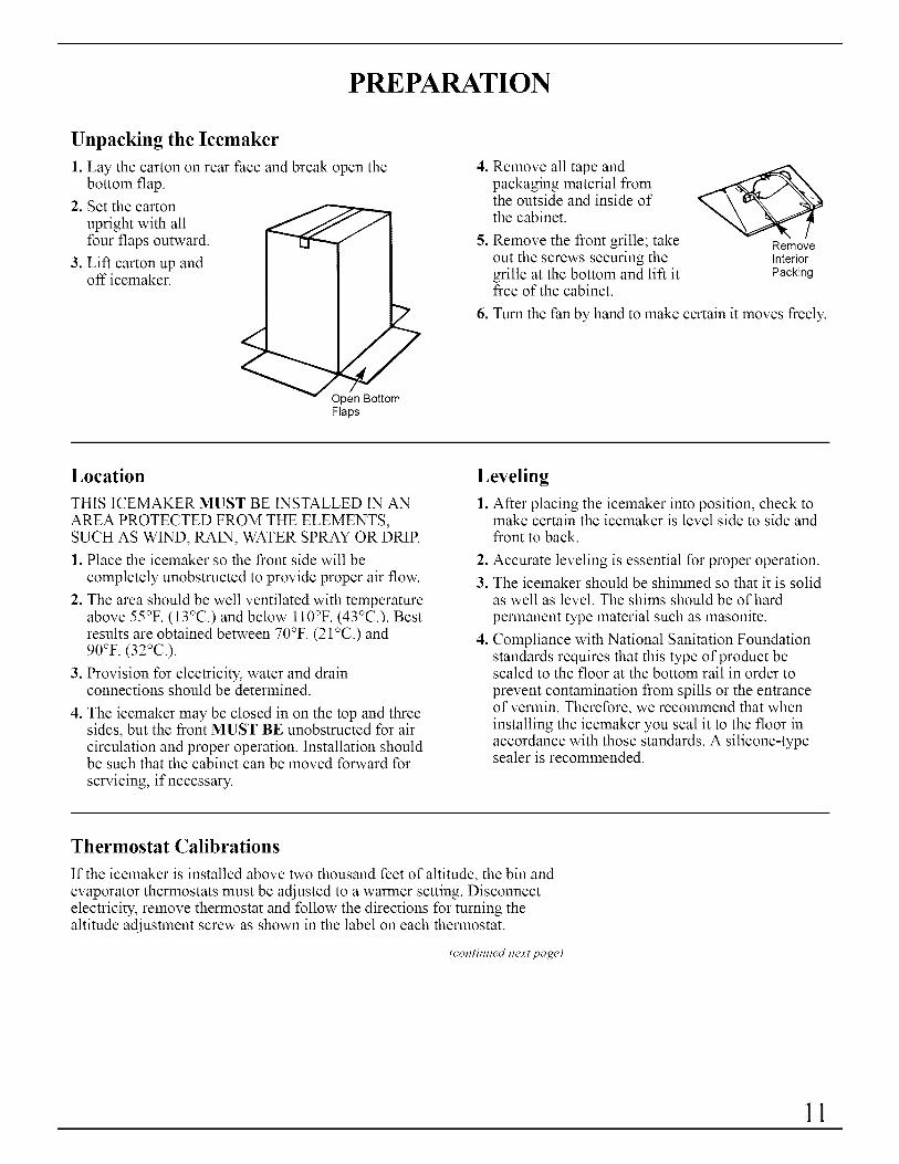
1. Lay the carton on rear face and break open thebottom flap.
2. Set the carton
upright with allfour flaps outward.
3. Lift carton up andoff icemaker.
"2
/
/
ttomFlaps
.
°
Remove all tape andpackaging material fromthe outside and inside ofthe cabinet.
Remove the front grille; takeout the screws securing thegrille at the bottom and lift itfree of the cabinet.
RemoveInterior
Packing
6. Turn the fan by hand to make certain it moves freely.
Location
THIS ICEMAKER MUST BE INSTALLED IN AN
AREA PROTECTED FROM THE ELEMENTS,SUCH AS WIND, RAIN, WATER SPRAY OR DRIP.
1. Place the icemaker so the front side will be
completely unobstructed to provide proper air flow.
2. The area should be well ventilated with temperatureabove 55°F. (13°C.) and below ll0°F. (43°C.). Bestresults are obtained between 70°F. (21 °C.) and90°F. (32°C.).
3. Provision for electricity, water and drainconnections should be determined.
4. The icemaker may be closed in on the top and threesides, but the front MUST BE unobstructed for aircirculation and proper operation. Installation shouldbe such that the cabinet can be moved forward for
servicing, if necessary.
Leveling
1. After placing the icemaker into position, check tomake certain the icemaker is level side to side andfront to back.
°
3.
°
Accurate leveling is essential for proper operation.
The icemaker should be shimmed so that it is solidas well as level. The shims should be of hardpermanent type material such as masonite.
Compliance with National Sanitation Foundationstandards requires that this type of product besealed to the floor at the bottom rail in order to
prevent contamination from spills or the entranceof vermin. Therefore, we recommend that wheninstalling the icemaker you seal it to the floor inaccordance with those standards. A silicone-typesealer is recommended.
Thermostat Calibrations
If the icemaker is installed above two thousand feet of altitude, the bin andevaporator thermostats must be adjusted to a warmer setting. Disconnectelectricity, remove thermostat and follow the directions for turning thealtitude adjustment screw as shown in the label on each thermostat.
(continued next page)
11
PREPARATION(continued)
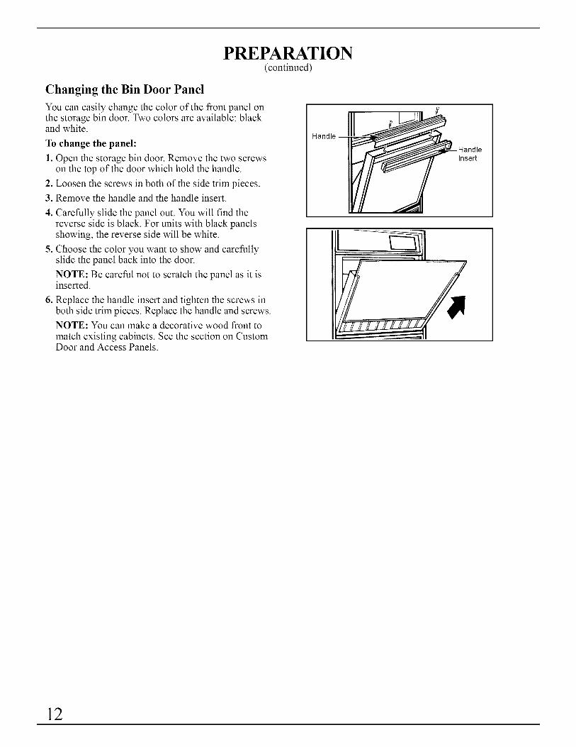
Changing the Bin Door Panel
You can easily change the color of the front panel onthe storage bin door. Two colors are available: blackand white.
To change the panel:
1. Open the storage bin door. Remove the two screwson the top of the door which hold the handle.
2. Loosen the screws in both of the side trim pieces.
3. Remove the handle and the handle insert.
4. Carefully slide the panel out. You will find thereverse side is black. For units with black panelsshowing, the reverse side will be white.
5. Choose the color you want to show and carefullyslide the panel back into the door.
NOTE: Be careful not to scratch the panel as it isinserted.
6. Replace the handle insert and tighten the screws inboth side trim pieces. Replace the handle and screws.
NOTE: You can make a decorative wood front to
match existing cabinets. See the section on CustomDoor and Access Panels.
Handle
Insert
1
12

Changing the Lower Access Panel
control panel removed. Electrical shock
1. Remove the screw from the top of the lower accesspanel and the two screws in the bottom grille area.Pull forward at the bottom, then down to removethe panel.
GrillArea
Screws
2. Remove the two screws from the top panel trim andremove the top trim.
/3. Carefully slide the panel out.
4. Choose the color you want to show and carefullyslide the panel back into the lower access panel.
NOTE: Be careful not to scratch the panel as itis inserted.
5. Replace the top trim and screws. Replace the loweraccess panel assembly and screws. The top of theaccess panel needs to be secured under the twometal tabs before replacing the screws.
NOTE: You can make a decorative wood front to
match existing cabinets. See the section on CustomDoor and Access Panels.
(continued next page)
13
CUSTOM DOOR AND ACCESS PANELS
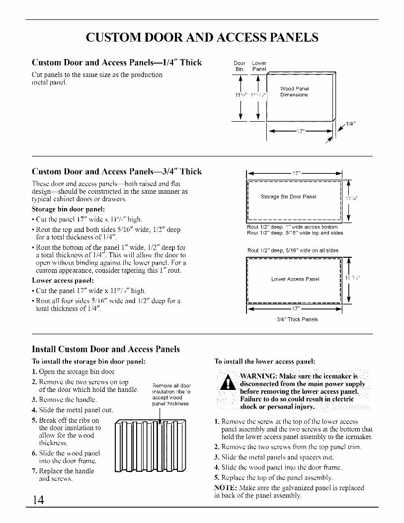
Custom Door and Access Panels--I/4" Thick
Cut panels to the same size as the productionmetal panel.
DoorBin
11//4"
LowerPanel
t11W_o"
Wood PanelDimensions
17"
Custom Door and Access Panels--3/4" Thick
These door and access panels--both raised and flatdesign--should be constructed in the same manner astypical cabinet doors or drawers.
Storage bin door panel:
• Cut the panel 17" wide x 111/4"high.
• Rout the top and both sides 5/16" wide, 1/2" deepfor a total thickness of 1/4".
• Rout the bottom of the panel 1" wide, 1/2" deep fora total thickness of 1/4". This will allow the door to
open without binding against the lower panel. For acustom appearance, consider tapering this 1" rout.
Lower access panel:
• Cut the panel 17" wide x 1115/I61"high.
• Rout all four sides 5/16" wide and 1/2" deep for atotal thickness of 1/4".
91 17" II,
-fStorage Bin Door Panel 11//4"
Rout 1/2" deep, 1" wide across bottomRout 1/2" deep, 5/16" wide top and sides
Rout 1/2" deep, 5/16" wide on all sides
__Lower Access Panel 5/_0"
,_ 17" Im,
3/4" Thick Panels
Install Custom Door and Access Panels
To install the storage bin door panel:
1. Open the storage bin door.
2. Remove the two screws on topof the door which hold the handle.
3. Remove the handle.
4. Slide the metal panel out.
5. Break off the ribs onthe door insulation toallow for the woodthickness.
6. Slide the wood panelinto the door frame.
7. Replace the handleand screws.
Remove all doorinsulation ribs toaccept woodpanel thickness
14
To install the lower access panel:
WARNING: Make sure the icemaker is
_ disconnected from the main powe r supplybefore removing the lower access panel.Failure to do so could result in electric
1. Remove the screw at the top of the lower accesspanel assembly and the two screws at the bottom thathold the lower access panel assembly to the icemaker.
2. Remove the two screws from the top panel trim.
3. Slide the metal panels and spacers out.
4. Slide the wood panel into the door frame.
5. Replace the top of the panel assembly.
NOTE: Make sure the galvanized panel is replacedin back of the panel assembly.

Vacation and Moving
"WARNING: Make sure the icemaker is
disconnected from the main power supplybefore removing the lower access panel.
Failure to do so could result in electricshock or personal injury.
To shut down the icemaker:
1. Disconnect the electrical power supply to theicemaker and turn the Cycle Control Knob to "OFF."
2. Remove all ice from the storage bin.
3. Shut off the water supply.
4. Remove the screw from the top of the lower accesspanel and the two screws from the grille area of thelower access panel, then remove the panel. Pullforward at the bottom, then down.
NORMAL
\ I /
0THIN - - THICK
ICE
OFF - "_
CYCLE
LowerAccessPanel
GrilleArea -- Screws
5. Disconnect the inlet and outlet lines to the watervalve. Allow these lines to drain and then reconnectto the valve.
6. Replace the lower access panel and screws. Thetop of the access panel needs to be secured underthe two metal tabs before replacing the screws.
Inlet
I
L.
7. Remove water from the drain lines and drain
water pan.
8. Before using again, clean the icemaker andstorage bin.
NOTE: All components of the icemaker arepermanently lubricated at the factory. They shouldnot require any additional oiling throughout thenormal life of the machine.
WaterPan
15
FREE STANDING INSTALLATION
For the Installer
When this icemaker is installed free standing (not under a counter) westrongly recommend that the bottom rear comers of the icemaker befastened to the floor to prevent accidental tipping.
INSTALLATION REQUIREMENTSIMPORTANT...Please Read Carefully
For the Electrician--Electrical Requirements
A 115 Volt, 60 Hz, AC only, 15 Amp fused electrical supply is required(time delay fuse or circuit breaker is recommended). It is recommended thata separate circuit, serving only this appliance, be provided. DO NOT use anextension cord.
ELECTRICAL GROUND IS REQUIRED ON THIS APPLIANCE.
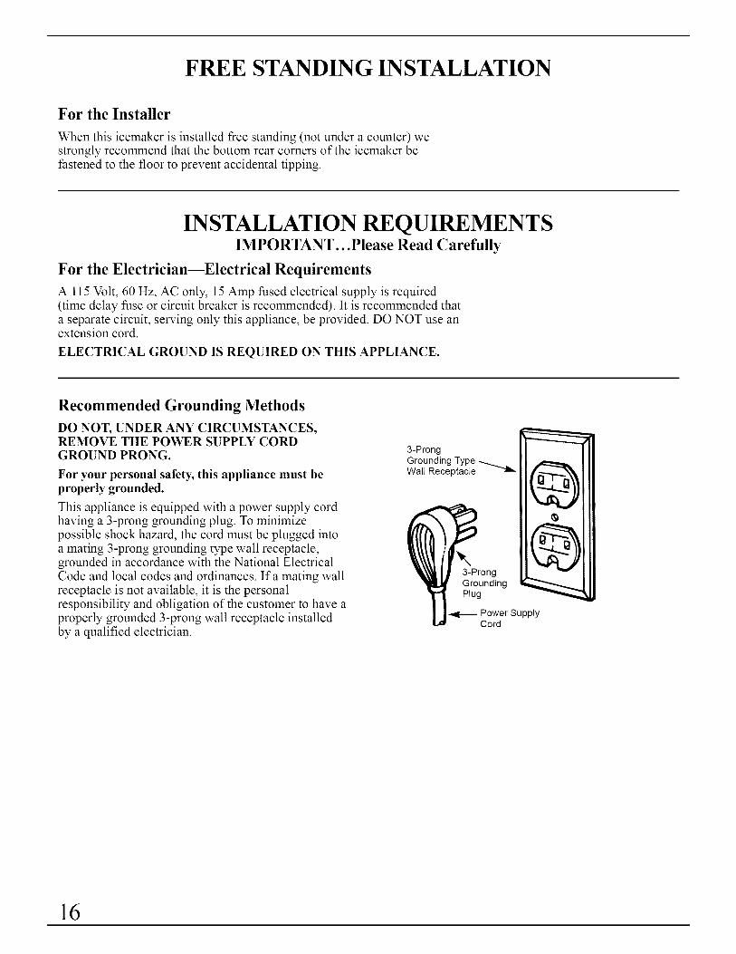
Recommended Grounding Methods
DO NOT, UNDER ANY CIRCUMSTANCES,REMOVE THE POWER SUPPLY CORDGROUND PRONG.
For your personal safety, this appliance must beproperly grounded.
This appliance is equipped with a power supply cordhaving a 3-prong grounding plug. To minimizepossible shock hazard, the cord must be plugged intoa mating 3-prong grounding type wall receptacle,grounded in accordance with the National ElectricalCode and local codes and ordinances. If a mating wallreceptacle is not available, it is the personalresponsibility and obligation of the customer to have aproperly grounded 3-prong wall receptacle installedby a qualified electrician.
3-ProngGrounding TypeWall Receptacle
3-ProngGroundingPlug
Power SupplyCord
16

Right end view
3/4" -'_ _ 237/8"
t 1
Water inlet
1/4" O.D. solenoid valve
water line. /compression \ /fitting at \ ,,/_ _ ,water valve _ ._'--------..... r'_?"
_L _" 1,1.'_, , _J 33/Z' '-_1/'/2" -i'-. ..... L [.
,,Bend field supplied water line to
Figure 1 connect to water valve fitting
l34W="
2V2" -_'_"
4" tong 5/8" I.D.rubber draintube--run to
open drain
[_NJr d --11/4" Min.
["_/4- "_ -- Hole for field3/4" _ supplied water line
\k-- /' i
_ ,%,_-.2,T_ / 0o-
34I/2" 9" TF_ i
.,/ 1 41/2"t0 \
y__ center line \
/, 18"-----4
Figure 2
UTILITIES
OBSERVE LOCAL CODES
Each installation is unique but will require:
• A cold water inlet of 1/4" O.D. soft coppertubing and a shutoff valve.
• Either a gravity drain system or a sump pumpto lift the water to an existing drain.
• An electrical branch circuit of 115 volt, 60 Hz.1 phase, with a 15 amp delayed action fuse orcircuit breaker.
FORTHE PLUMBER
Connect to water. (Observe local codes.)• Use 1/4" O.D. soft copper tubing for the coldwater supply.• Provide a convenient manual shutoff valve in thewater line.
• Position the tubing so it can enter the accesshole located in the right-hand rear of theicemaker cabinet. The tubing should extendbeyond the cabinet front so when the icemakeris pushed back in position it will reach the waterinlet location in the front. See Figure 1.
NOTE: Always purge the water line beforemaking the final connection to the inlet of thewater valve to prevent possible water valvemalfunction.
With the icemaker in its permanent location,bend the tubing to meet the connection atthe water valve. The garden hose threadedcompression fitting is found in the parts bag.This joint provides a convenient disconnectfor service. Be sure the tubing is clear ofcompressor, to prevent rattle.
LEVELING
• After placing the icemaker into position, checkto make certain the icemaker is level side to sideand front to back.
• Accurate leveling is essential for properoperation.
• The icemaker should be shimmed so that it issolid as well as level. The shims should be ofhard permanent type material such as masonite.
• Compliance with National SanitationFoundation standards requires that this type ofproduct be sealed to the floor at the bottom railin order to prevent contamination from spills orthe entrance of vermin. Therefore, werecommend that when installing the icemakeryou seal it to the floor in accordance with thosestandards. A silicone-type sealer is recommended.
ALTERNATEMETHOD
If a drain connection directly below thedrain tube outlet is not available, install aUL-listed drain pump in the rear compartmentof the icemaker.
Drain pump specifications:• UL-listed and have a UL-listed, 120VAC, 3-wiregrounded service cord• Overall outside dimensions (maximum):15" wide x 6" deep x 91/2"high
• Pump flow rate (minimum): 24.0 gph (0.4 gpm)@ 12 feet lift
• Operating temperature range 55°E to 110°E(13°C. to 43°C.)
(continued next page)
17
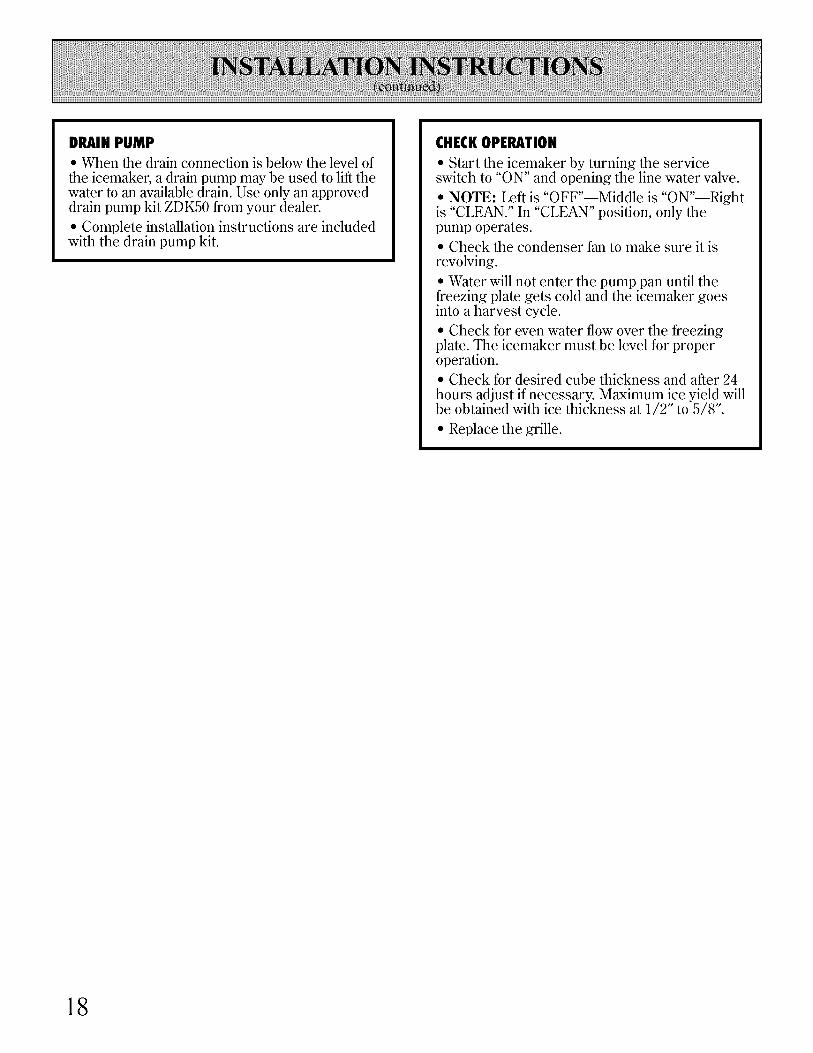
DRAIN PUMP
• When the drain connection is below the level of
the icemaker, a drain pump may be used to lift thewater to an available drain. Use only an approveddrain pump kit ZDK50 from your dealer.
• Complete installation instructions are includedwith the drain pump kit.
CHECKOPERATION
• Start the icemaker by turning the serviceswitch to "ON" and opening the line water valve.
• NOTE: Left is "OFF"--Middle is "ON"--Rightis "CLEAN." In "CLEAN" position, only thepump operates.• Check the condenser fan to make sure it isrevolving.
• Water will not enter the pump pan until thefreezing plate gets cold and the icemaker goesinto a harvest cycle.• Check for even water flow over the freezingplate. The icemaker must be level for properoperation.• Check for desired cube thickness and after 24hours adjust if necessary. Maximum ice yield willbe obtained with ice thickness at 1/2" to 5/8".
• Replace the grille.
18
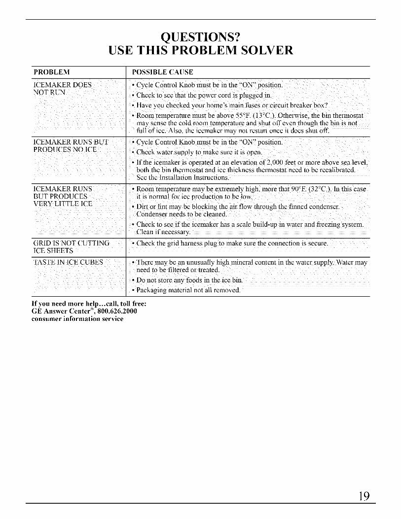
QUESTIONS?USE THIS PROBLEM SOLVER
PROBLEM
ICEMAKER DOESNOT RIfN
ICEMAKER RUNS BUTPRODUCES NO ICE
ICEMAKER RUNSBUT PRODUCESVERY LITTLE ICE
GRID IS NOT CUTTINGICE SHEETS
TASTE 1N ICE CUBES
POSSIBLE CAUSE
• Cycle Control Knob must be in the "ON" position.
• Check to see that the power cord is plugged in.
• Have you checked your home's main fuses or circuit breaker box?
• Room temperature must be above 55°F. (13°C.). Otherwise, the bin thermostatmay sense the cold room temperature and shut off even though the bin is notfull of ice. Also. the icemaker may not restart once it does shut off.
• Cycle Control Knob must be in the "ON" position.
• Check water supply to make sure it is open.
• If the icemaker is operated at an elevation of 2,000 feet or more above sea level,both the bin thermostat and ice thickness thermostat need to be recalibrated.See the Installation Instructions.
• Room temperature may be extremely high, more that 90°F. (32°C.). In this caseit is normal for ice production to be low.
• Dirt or lint may be blocking the air flow through the finned condenser.Condenser needs to be cleaned.
• Check to see if the icemaker has a scale build-up in water and freezing system.Clean if necessary.
• Check the grid harness plug to make sure the connection is secure.
• There may be an unusually high mineral content in the water supply. Water mayneed to be filtered or treated.
• Do not store any foods in the ice bin.
• Packaging material not all removed.
If you need more help...call, toll free:GE Answer Center <"_,800.626.2000consumer information service
19

We'll Be ThereWith the purchase of your new GE appliance, receive the assurance that if you ever needinformation or assistance from GE, we'll be there. All you have to do is call-toll-free!
GEAnswerCenter®800.626.2000
®Whatever your question about any GE major appliance, GE Answer Centerinformation setsTice is m_ailable to help. Your call-and your question- will beanswered promptly and courteously. And you can call any time. GE AnswerCenter ®sets_ice is open 24 hours a day, 7 days a week.
In-HomeRepairService800-GE-CARES(80&432-2737)AGE consumer sms_ice professional will provide expert repair sets,ice,scheduled at a time that's convenient for you. Many GE Consumer Sets,icecompany-operated locations of*er you sets,ice today or tomorrow, or at yourconvenience (7:00 a.ln. to 7:00 p.m. weekdays, 9:00 a.m. to 2:00 p.m. Saturdays).Our f)tctoxy-trained technicians know your appliance inside and out-so mostrepairs can be handled in just one visit.
_o
ISECTIONA-A
ForCustomersWithSpecialNeeds...800.626.2000
Upon request, GE will provideBraille controls for a variety, ofGE appliances, and a brochure toassist in planning a barrier4i'eekitchen for persons with limitedlnobility. To obtain these items,fl'ee of charge, call 800.626.2000.
Consumers with impaired hearing or speech who haveaccess to a TDD or a conventional teletype_Titer maycall 800-TDD-GEAC (800-833-4322) to requestinformation or sets_ice.
ServiceContracts800-626-2224
You can have the secure feeling that GE Consumer Sets,ice will still be thereafter your warranty, expires. Purchase a GE contract while your warranty, is stillin effect and you'll receive a substantial discount. With a lnultiple-year contract,you're assured of flmlre sets,ice at todw's prices.
PartsandAccessories800-626-2002Individuals qualified to service their own appliances canhave parts or accessories sent directly to their home. TheGE parts system provides access to over 47,000 parts...andall GE Genuine Renewal Parts are flflly warranted. VISA,MasterCard and Discover cards are accepted.
User maintenance instructions contained in this booklet
cover procedures intended to be performed by any user.Other servicing generally should be referred to qualifiedservice personnel. Caution must be exercised, sinceimproper servicing may cause unsafe operation.
20
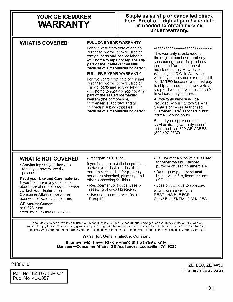
YOUR GEICEMAKER
WARRANTYStaple sales slip or cancelled checkhere. Proof of original purchase date
is needed to obtain serviceunder warranty.
WHAT IS COVERED FULL ONE-YEAR WARRANTY
For one year from date of originalpurchase, we will provide, free ofcharge, parts and service labor inyour home to repair or replace anypart of the icemaker that failsbecause of a manufacturing defect.FULL FIVE-YEAR WARRANTY
For five years from date of originalpurchase, we will provide, free ofcharge, parts and service labor inyour home to repair or replace anypart of the sealed icemakingsystem (the compressor,condenser, evaporator and allconnecting tubing) that failsbecause of a manufacturing defect.
This warranty is extended tothe original purchaser and anysucceeding owner for productspurchased for use in the 48mainland states, Hawaii andWashington, D.C. In Alaska thewarranty is the same except that itis LIMITED because you must payto ship the product to the serviceshop or for the service technician'stravel costs to your home.
All warranty service will beprovided by our Factory ServiceCenters or by our AuthorizedCustomer Care ® servicers duringnormal working hours.
Should your appliance needservice, during warranty periodor beyond, call 800-GE-CARES(800-432-2737).
WHAT IS NOT COVERED• Service trips to your home to
teach you how to use theproduct.
Read your Use and Care material.If you then have any questionsabout operating the product pleasecontact your dealer or ourConsumer Affairs office at theaddress below, or call, toll free:GE Answer Center ¢800.626.2000consumer information service
• Improper installation.
If you have an installation problem,contact your dealer or installer.You are responsible for providingadequate electrical, plumbing andother connecting facilities.
• Replacement of house fuses orresetting of circuit breakers.
• Use of a non-approved DrainPump Kit.
• Failure of the product if it is usedfor other than its intendedpurpose or used commercially.
• Damage to product causedby accident, fire, floods or actsof God.
• Loss of food due to spoilage.WARRANTOR IS NOTRESPONSIBLE FORCONSEQUENTIAL DAMAGES.
Some states do not allow the exclusion or limitation of incidental or consequential damages, so the above limitation or exclusionmay not apply to you. This warranty gives you specific legal rights, and you may also have other rights which vary from state to state.
To know what your legal rights are in your state, consult your local or state consumer affairs office or your state's Attorney General.
Warrantor: General Electric Company
If further help is needed concerning this warranty, write:ManagermConsumer Affairs, GE Appliances, Louisville, KY 40225
2180919
Part No. 162D7745P002Pub. No. 49-6857
ZDIB50, ZDIW50Printed in the United States
2!

NOTES
22
Monogram.
Manual del usuario e
instrucciones parala instalaci6n
para ZDIB50ZDIW50
M_tquina para hacer hielo
General Electric CompanyLouisville, KY40225
Monogram.":"
Mdquina para hacer hMo
Pub. No. 49-6857
Parl No. 162D7745P002

Introducci6n
Su nueva mfiquina para hacer hielo Monogram esuna afirmacidn elocuente de estilo, comodidad yflexibilidad en la planeaci6n de su cocina. Ya seaque la elija por la pureza de su disefio, por lascaracteristicas fisicas o por la constante atenci6n aldetalleIO por todas estas razonesIencontrarfi quela conbinaci6n de forma y funci6n de su maquina parahacer hielo Monogram es superior y darfi una gransatisfacci6n durante los afios venideros.
La mfiquina para hacer hielo Monogram fue disefiadapara proporcionar la flexibilidad requerida paraadaptarse a los gabinetes de su cocina.
La informacidn contenida en las siguientes pfiginas leayudarfi a operar y a mantener de manera apropiada sumfiquina para hacer hielo.
Si requiere una lista de distribuidores, o si tiene otraspreguntas, por favor llamd a GE Answer Center _R:(800.626.2000).
Contenido
Cuidado y limpieza ................. 7-10
Cambio del bombillo ........... 10
Componentes interiores de la
mfiquina para hacer hielo ....9
Condensador .......................... 7
Filtrado y tratamiento
del agua ............................. 10
Sistema para fabricar hielo .... 8
Superficies exteriores ............. 7
Controles ....................................... 6
Caracteristicas ............................... 6
Instrucciones de instalacidn.. 16-18
Instalacidn independiente .... 16
Instrucciones para
la conexidn a tierra ............ 16
Requerimientos eldctricos .... 16
Instrucciones de operacidn ....... 5, 6
Instrucciones de seguridad ............ 4
Localizacidn de nfmeros de
serie y de modelos .............. 3, 6
Preparacidn ........................... 1l-15
Calibraciones del
termostato .......................... 11
Cdmo cambiar el panel del
depdsito de la puerta ......... 12
Cdmo cambiar el panel
inferior de acceso .............. 13
Cdmo desempacar la
mfiquina para hacer hielo .. 11
Localizacidn ......................... 11
Nivelacidn ............................ 11
Puerta y paneles de
acceso a la medida ............ 14
Vacaciones y mudanzas ....... 15
Registro del aparato ...................... 3
Servicios al consumidor .............. 20
Solucidn a los problemas ............ 19
Garantia ...................................... 21
iPre#untas?Llamk a GEAnswer [email protected]
2
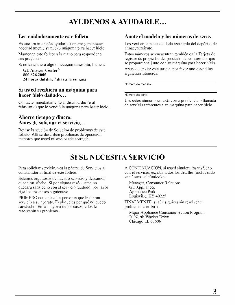
AYUDENOS A AYUDARLE...
Lea cuidadosamente este folleto.
Es nuestra intencidn ayudarle a operar y manteneradecuadamente su nuevo mfiquina para hacer hielo.
Mantenga este folleto a la mano para responder asus preguntas.
Si no entendiera algo o necesitara asesoria, llame a:
GE Answer Center _"_800.626.2000
24 horas del dia, 7 dias a la semana
Si usted recibiera un mfiquina parahacer hielo dafiado...
Contacte inmediatamente al distribuidor (o alfabricante) que le vendi6 la mfiquina para hacer hielo.
Ahorre tiempo y dinero.Antes de solicitar el servicio...
Revise la seccidn de Solucidn de problemas de estefolleto. Alli se describen problemas de operacidnmenores que usted mismo puede corregir.
Anote el modelo y los nfimeros de serie.
Los verfi en la placa del lado izquierdo del depdsito dealmacenamiento.
Estos nfimeros se encuentran tambidn en la Tarjeta deregistro de propiedad del producto del consumidor quese proporciona junto con su mfiquina para hacer hielo.
Antes de enviar esta tarjeta, por favor anote aqui lossiguientes nfimeros:
NOmero de modelo
NOmero de serie
Use estos nflmeros en toda correspondencia o llamadade servicio referentes a su mfiquina para hacer hielo.
SI SE NECESITA SERVICIO
Para solicitar servicio, vea la pfigina de Servicios alconsumidor al final de este folleto.
Estamos orgullosos de nuestro servicio y deseamosquede satisfecho. Si por alguna razdn usted noquedara satisfecho con el servicio recibido, por favorsiga los tres pasos siguientes:
PRIMERO contacte alas personas que le dieronservicio a su aparato. Expliqueles por qud no qued6satisfecho. En la mayoria de los casos, ellos leresolverfin su problema.
A CONTINUACION, si usted siguiera insatisfechocon el servicio, escriba todos los detalles (incluyendosu nfimero telefdnico) a:
Manager, Consumer RelationsGE AppliancesAppliance ParkLouisville, KY 40225
FINALMENTE, si afin siguiera sin resolver elproblema, escribir a:
Maior Appliance Consumer Action Program20 North Wacker Drive
Chicago, IL 60606
3
INSTRUCCIONES DE SEGURIDADLea todas las instrucciones antes de usar este electrodom stico.
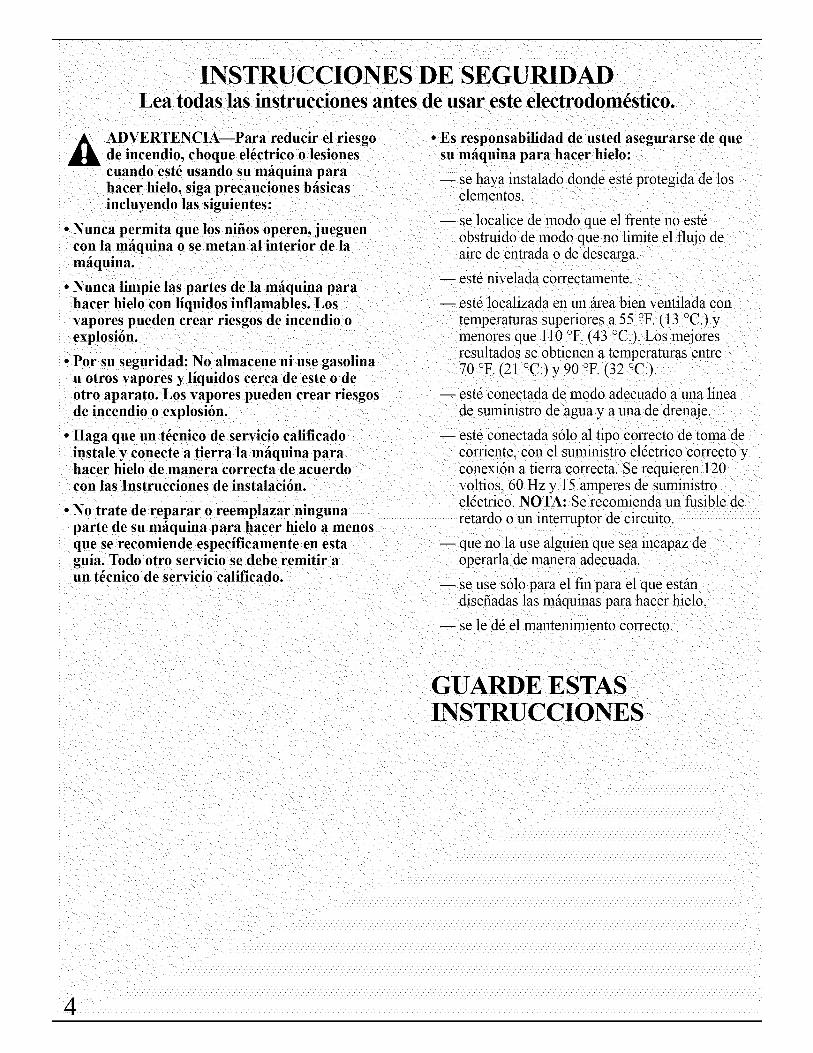
A ADVERTENCIA--Para reducir el riesgo • Es responsabilidad de usted asegurarse de quede incendio, choque el6ctrico o lesiones su mfiquina para hacer hielo:cuando est_ usando su mfiquina para . . ........ ... ,......... -- se nava lnstala(lo (lon(le este protegloa ae lOSnacer nlelO, slga precanclones oaslcas
incluyendo las siguientes:
• Nunca permita que los nifios operen, jueguencon la mfiquina o se metan al interior de lamfiquina.
• Nunca limpie las partes de la mfiquina parahacer hielo con liquidos inflamables. Losvapores pueden crear riesgos de incendio oexplosi6n.
• Por su seguridad: No almacene ni use gasolinau otros vapores y liquidos cerca de este o deotro aparato. Los vapores pueden crear riesgosde incendio o explosi6n.
• Haga que un t6cnico de servicio calificadoinstale y conecte a tierra la mfiquina parahacer hielo de manera correcta de acuerdocon las Instrucciones de instalaci6n.
• No trate de reparar o reemplazar ningunaparte de su m_iquina para hacer hielo a menosque se recomiende especificamente en estaguia. Todo otro servicio se debe remitir aun t6cnico de servicio calificado.
elementos.
se localice de modo que el frente no estdobstruido de modo que no limite el flujo deaire de entrada o de descarga.
-- estd nivelada correctamente.
estd localizada en un fireabien ventilada contemperaturas superiores a 55 °F. (13 °C.)ymenores que 110 °F. (43 °C.). Los mejoresresultados se obtienen a temperaturas entre70 °F. (21 °C.) y 90 °F. (32 °C.).
estd conectada de modo adecuado a una lineade suministro de agua y a una de drenaje.
-- estd conectada s61oal tipo correcto de toma decorriente, con el suministro eldctrico correcto yconexi6n a tierra correcta. Se requieren 120voltios, 60 Hz y 15 amperes de suministroeldctrico. NOTA: Se recomienda un fusible deretardo o un interruptor de cireuito.
-- que no la use alguien que sea incapaz deoperarla de manera adecuada.
se use s61opara el fin para el que estfindisefiadas las mfiquinas para hacer hielo.
se le dd el mantenimiento correcto.
GUARDE ESTASINSTRUCCIONES

OPERACION DE SU MAQUINA PARA HACER HIELO
C6mo funciona la mfiquina para hacer hielo
1. E1 agua circula constantemente sobre una placa decongelacidn. A medida que el agua se enfria parallegar a congelarse, los minerales que contiene elagua son expulsados. Esto produce una capadelgada de hielo con baio contenido de minerales.
NOTA: La mfiquina para hacer hielo estfi disefiadapara fabricar hielo transparente con la mayoria delas fuentes de suministro de agua todos los dias.Si los resultados no son satisfactorios, el aguapuede necesitar filtrarse o tratarse. ConsulteFiltracidn y tratamiento del agua en la seccidnCuidado y limpieza.
2. Cuando se haya alcanzado el espesor deseado, laplaca de hielo se libera y se desliza hacia la rejillacortadora. Esta rejilla divide la placa de hielo encubos individuales.
3. E1 agua que contiene los minerales expulsados sedrena despuds de cada ciclo de congelacidn.
4. E1 agua fresca entra en la mfiquina para el siguienteciclo de congelacidn.
5. Los cubos caen en el depdsito de almacenamiento.Cuando el depdsito estfi lleno, la mfiquina parahacer hielo se apaga automfiticamente y se vuelve aencender cuando se necesita mils hielo.
Notas acerca de esta mfiquina para hacer hielo
• E1 agua entra s61o durante el ciclo dedescongelamiento. Por lo tanto el primer ciclo seacabarfi sin tener agua en el sistema.
• Como las temperamras ambiente y del agua varian,asi tambidn variarfi la cantidad de hielo producido.Eso significa que las temperamras de operacidn milsaltas resultarin en produccidn de hielo reducida.
• La miquina para hacer hielo se apagari cuando elhielo en el depdsito de almacenamiento toca lafuente del termostato del depdsito y ciclariautomiticamente para mantener lleno el depdsito.
E1 depdsito de almacenamiento no se refrigera yalgfin derretimiento ocurriri. Eso, tambidn, varia conla temperatura ambiente.
La miquina para hacer hielo necesita buenacirculacidn de aire para funcionar eficazmente.Mantenga limpios la rejilla frontal y el condensador.
E1 sistema de agua, incluyendo el filtro dentro de lavilvula de solenoide de entrada de agua, se necesitalimpiar periddicamente para buena circulacidn. Lasinstrucciones se encuentran en el panel de la puertainterior.
(pase a hl pc_gina si_tiente)
5
OPERACION DE SU MAQUINA PARA HACER HIELO(pase)
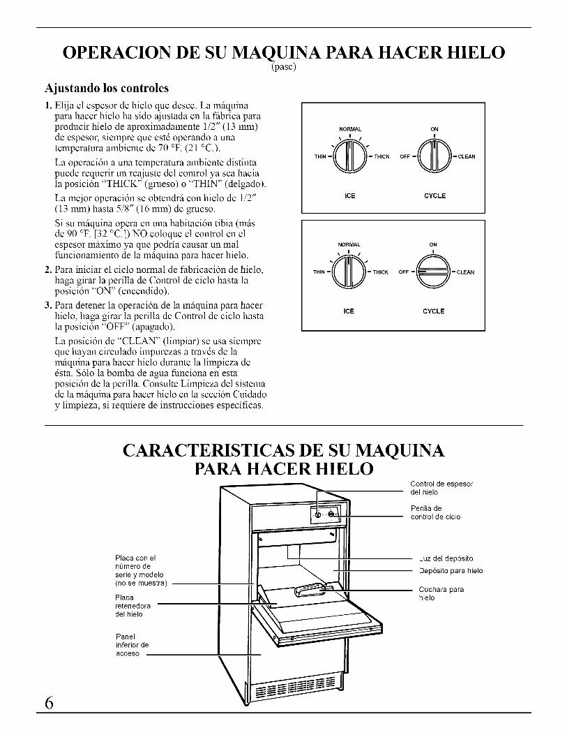
Ajustando los controles
1. Elija el espesor de hielo que desee. La milquinapara hacer hielo ha sido ajustada en la filbrica paraproducir hielo de aproximadamente 1/2" (13 mm)de espesor, siempre que estd operando a unatemperamra ambiente de 70 °F. (21 °C.).
La operacidn a una temperamra ambiente distintapuede requerir un reajuste del control ya sea haciala posicidn "THICK" (grueso) o "THIN" (delgado).
La mejor operacidn se obtendril con hielo de 1/2"(13 mm) hasta 5/8" (16 mm) de grueso.
Si su milquina opera en una habitacidn tibia (milsde 90 °F. [32 °C.]) NO coloque el control en elespesor milximo ya que podria causar un malfuncionamiento de la milquina para hacer hielo.
2. Para iniciar el ciclo normal de fabricacidn de hielo,haga girar la perilla de Control de ciclo hasta laposicidn "ON" (encendido).
3. Para detener la operacidn de la milquina para hacerhielo, haga girar la perilla de Control de ciclo hastala posicidn "OFF" (apagado).
La posicidn de "CLEAN" (limpiar) se usa siempreque hayan circulado impurezas a travds de lamilquina para hacer hielo durante la limpieza dedsta. $61o la bomba de agua funciona en estaposicidn de la perilla. Consulte Limpieza del sistemade la milquina para hacer hielo en la secci6n Cuidadoy limpieza, si requiere de instrucciones especificas.
THIN
NORMAL
THICK
ONI
OFF -@- CLEAN
ICE CYCLE
NORMAL ON
\ I / I
0" @THIN - - THICK OFF - - CLEAN
ICE CYCLE
6
CARACTERISTICAS DE SU MAQUINAPARA HACER HIELO
Placa con elnQmero de
serie y modelo(no se muestra)
Placaretenedoradel hielo
I
Panelinferiordeacceso
Control de espesordel hielo
Perilla decontrol de ciclo
IIII Luz del dep6sito
Dep6sito para hielo
Cuchara parahielo

CUIDADO Y LIMPIEZA
Inspeccione y limpie periddicamente la mfiquina parahacer hielo de modo que siga funcionando a sumfixima eficiencia y para prevenir una falla premamrade los componentes del sistema.
Tanto el sistema de fabricacidn de hielo como el
condensador enfriado por aire necesitan ser limpiadosde manera regular.
Los minerales expulsados del agua circulante duranteel ciclo de congelacidn a la larga formarfin un depdsitoescamoso duro en el sistema de agua que evitarfi laliberacidn rfipida del hielo de la placa de congelacidn.
Limpie periddicamente el sistema de hielo y aguapara quitar las sales minerales escamosas que seforman. La frecuencia con que se haga la limpiezadependerfi de la dureza del agua. Si el agua es dura(15/20 granos/galdn), la limpieza puede requerirsecon tanta frecuencia como lo seria cada seis meses.
Un condensador sucio o tapado:
• evita el fluio correcto de aire
• reduce la capacidad de fabricar hielo
• causa temperaturas de operaci6n superiores a lasrecomendadas que pueden llevar auna falla de loscomponentes.
Limpieza de las superficies exteriores
Lave las superficies exteriores de esmalte y los empaquescon agua tibia y jab6n o detergente suave. Eniuague yseque. E1 uso regular de un buen limpiador domdsticopara aparatos y de cera ayudarfi a proteger el acabado.
No use limpiadores abrasivos en superficiesesmaltadas ya que pueden rayar el acabado.
Limpieza del condensador
hacer hielo est_ en posici6n de "OFF"(apagado) y desconectada del suministroprincipal de energia el_ctrica. La mfiquinapodria encenderse sfibitamente si no estfidesconectada. La rotaci6n de las aspas deicondensador, las afiladas hojas delcondensador y las tuberias calientes podriancausar lesiones permanentes en las personas.
• Las hojas del condensador pueden doblarsecon facilidad. Tenga cuidado cuando limpiecon aspiradora el condensador para evitarque las hoj as se doblen.
1. Desconecte el suministro de corriente eldctrica quealimenta la mfiquina para hacer hielo y ponga laperilla de Control de ciclo en "OFF" (apagado).
2. Quite los dos tomillos del firea de la reiilla en elpanel inferior de acceso.
3. Tire hacia adelante y hacia abaio para quitar el panel.
4. Quite la suciedad y la pelusa de las hoias delcondensador y del compartimiento de la unidad conun accesorio para cepillar conectado auna aspiradora.
5. Vuelva a colocar el panel inferior de acceso y lostornillos. La parte superior del panel de accesoneeesita asegurarse debajo de las dos lengiietasde metal antes de volver a colocar los tornillos.
6. Conecte la mfiquina para hacer hielo y haga girar laperilla de Control de ciclo hasta la posicidn de"ON" (encendido).
IPanelinferior deacceso
Area de
la rejilla
Tornillos
(pase a la pc'lgina si_tiente)
7

CUIDADO Y LIMPIEZA(pase)
Limpieza del sistema de la mfiquina para hacer hielo
A DVERTENCIA: La mavoria de loslimpiadores para mfiquinas se hacen abase de ficido citrico o fosf6rico y
pueden causar irritaci6n incluso despu6s de serdiluidos. En el caso de contacto con los ojos,enjuague los ojos meticulosamente con agua yllame a un m6dico de inmediato. En caso de
contacto con la piel, enjuague bien con agua. Sise ingiere, d61e a la persona grandes cantidadesde agua y llame a un m6dico de inmediato. Noinduzca el v6mito. MANTENGASE FUERADEL ALCANCE DE LOS NIlqOS.
1. Coloque la perilla de Control de ciclo en posicidnde "OFF" (apagado).
Colector del .,h l Icableado eleotrioo [ = =1I I
I l_
Tornillos (largos)
2. Quite los dos tomiilos y deslice la r@ila cortadorade hielo hacia adelante, sacfindola de las dosranuras cercanas a la bandeja para agua.
3. Desconecte el colector de1cableado eldctri¢o.
P_CAUCION: Cualquier cantidad de hieloque quede en la rejilla deberfi derretirse bajoagna tibia corriente. Si trata de quitar lostrozos de hielo de !a rejilla puede estirar y
4. Quite todo el hielo del depdsito de hielo y de laplaca de congelacidn.
Bandeja para aguaii
del
desagQe
I5. Drene la bandeja para agua quitando el tapdn de
desagt_e y luego vuelva a colocarlo.
8
.
.
Vierta 1/2 galdn(1.9 L) de aguacaliente del grifoen la bandeja paraagua* y haga girarla perilla de Controlde ciclo hasta la
posicidn "CLEAN"
NOR ON
- CLEAN
(limpiar). Esto calentarfi el sistema para hacer milsefectiva la accidn de la solucidn limpiadora. Dejeque circule durante cinco minutos. Mientras el aguadel grifo estfi circulando, prepare la solucidnlimpiadora. Mezcle 6 onzas (170 g) de ficido citricoo fosfdrico en polvo con 1/2 galdn (1.9 L) de aguacaliente. (Los cristales de ficido citrico y fosfdricoestfin disponibles o pueden ordenarse en muchasfarmacias y tiendas de materiales cientificos.)
Los limpiadores comerciales para mfiquinas dehacer hielo (liquidos) tambidn los tiene sudistribuidor o las tiendas que venden partes pararefrigeracidn. Mezcle de acuerdo con lasinstrucciones de las etiquetas (la cantidad totaldebe ser de 1/2 galdn [1.9 L]).
Haga girar la perilla de Control de ciclo hasta laposicidn "OFF" (apagado) y desagt_e la bandejade agua. (Vea el paso 5.)
° Coloque la perilla de Control de ciclo en "CLEAN"(limpiar) y vierta lentamente la soluci6n limpiadoracaliente en la bandeja para agua.* (Si la soluci6nhace espuma mientras la estfi vertiendo, esperehasta que deje de hacer espuma.) Luego afiada loque queda de la soluci6n.
Permita que la solucidn circule hasta que se hayandisuelto los residuos acumulados (de 15 a 20minutos). Una formacidn de residuos escamososmuy grande puede requerir de una limpieza repetidacon una cantidad de solucidn limpiadora nueva.
°
10.
Para limpiar las acumulaciones en las pestafiaslaterales de la placa de congelacidn utiliceguantes de hule y talle con una fibra plfistica noabrasiva o con un cepillo de nylon empapado ensolucidn limpiadora.
No se quite los guantes de hule cuando drene lasolucidn limpiadora. Coloque la perilla de Controlde ciclo en "OFF" (apagado) y vacie la bandejapara agua. (Vea el paso 5.)
Vuelva a colocar el tapdn y agregue 1/2 galdn(1.9 L) de agua limpia.* Haga girar la perilla deControl de ciclo hasta la posicidn "CLEAN"(limpiar), deje que circule durante 5 minutos yluego drene. Repita el proceso de enjuague.
* Para facilitar el vertido del agua y de la solucidnlimpiadora use un recipiente con capacidad para 1 o2 tazas.
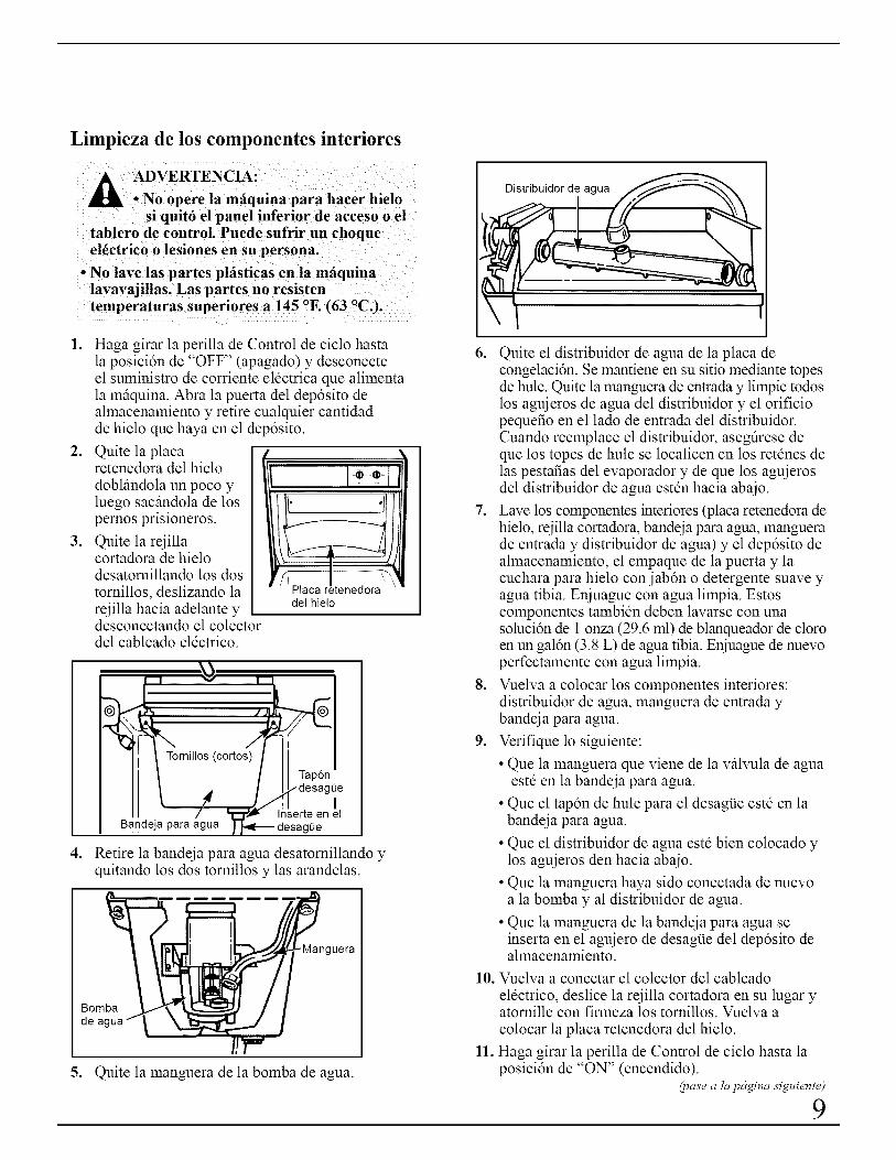
Limpieza de los componentes interiores
si quit6 el panel inferior de acceso o eltablero de control. Puede sufrir un choqueel_ctrico o lesiones en su persona.
• No lave las partes plfisticas en la mfiquinalavavajillas. Las partes no resistentemperaturas superiores a 145 °E (63 0C.).
.
.
.
Haga girar la perilla de Control de ciclo hastala posicidn de "OFF" (apagado) y desconecteel suministro de corriente eldctrica que alimentala mfiquina. Abra la puerta del dep6sito dealmacenamiento y retire cualquier cantidadde hielo que haya en el dep6sito.
Quite la placaretenedora del hielo
doblfindola un poco yluego sacfindola de lospemos prisioneros.
Quite la rejillacortadora de hielodesatomillando los dostornillos, deslizando lareiilla hacia adelante ydesconectando el colectordel cableado eldctrico.
del hielo
IInserte en el
_gee
4. Retire la bandeia para agua desatomillando yquitando los dos tornillos y las arandelas.
Bombade agua
guera
5. Quite la manguera de la bomba de agua.
Distribuidor de agua
6. Quite el distribuidor de agua de la placa decongelacidn. Se mantiene en su sitio mediante topesde hule. Quite la manguera de entrada y limpie todoslos aguieros de agua del distribuidor y el orificiopequefio en el lado de entrada del distribuidor.Cuando reemplace el distribuidor, asegfirese deque los topes de hule se localicen en los retdnes delas pestafias del evaporador y de que los aguierosdel distribuidor de agua estdn hacia abaio.
7. Lave los componentes interiores (placa retenedora dehielo, reiilla cortadora, bandeia para agua, manguerade entrada y distribuidor de agua) y el dep6sito dealmacenamiento, el empaque de la puerta y lacuchara para hielo con jab6n o detergente suave yagua tibia. Eniuague con agua limpia. Estoscomponentes tambidn deben lavarse con unasoluci6n de 1 onza (29.6 ml) de blanqueador de cloroen un gal6n (3.8 L) de agua tibia. Eniuague de nuevoperfectamente con agua limpia.
8. Vuelva a colocar los componentes interiores:distribuidor de agua, manguera de entrada ybandeia para agua.
9. Verifique lo siguiente:
• Que la manguera que viene de la vfilvula de aguaestd en la bandeia para agua.
• Que el tapdn de hule para el desagt_e estd en labandeia para agua.
• Que el distribuidor de agua estd bien colocado ylos aguieros den hacia abaio.
• Que la manguera haya sido conectada de nuevoa la bombay al distribuidor de agua.
• Que la manguera de la bandeia para agua seinserta en el aguiero de desagiJe del depdsito dealmacenamiento.
10. Vuelva a conectar el colector del cableado
eldctrico, deslice la rejilla cortadora en su lugar yatomille con firmeza los tomillos. Vuelva a
colocar la placa retenedora del hielo.
11. Haga girar la perilla de Control de ciclo hasta laposici6n de "ON" (encendido).
(pase a/clpc_gina si_tiente)
9

CUIDADO Y LIMPIEZA(pase)
Filtrado y tratamiento del agua
En la mayoria de las fireas seria beneficioso filtrar otratar el agua que alimenta la mfiquina para hacerhielo. Esto puede mejorar la confiabilidad de lamfiquina, reducir el mantenimiento del sistema deagua y producir la mejor calidad de hielo.
La instalacidn de un alimentador de polifosfato por logeneral reducirfi la formacidn de acumulaciones desales y la mfiquina para hacer hielo requerirfi delimpiezas menos frecuentes.
Los sistemas municipales de agua por lo general sontratados con cloro para mantener un suministro deagua potable libre de riesgos. Los filtros de carbdnactivado por lo general serfin suficientes para quitar elcloro residual del agua y reducir las manchas en lassuperficies de los materiales de acero inoxidable de lamfiquina para hacer hielo.
Para mayor informacidn sobre el filtrado ytratamiento del agua, consulte con el distribuidor alque le compr6 la mfiquina para hacer hielo.
Cambio de la bombilla
A DVERTENCIA: Antes de quitar labombilla, desconecte la mfiquina parahacer hielo o bien desconecte la
electricidad que alimenta a la mfiquina parahacer hielo desde la fuente de energiaprincipal. Puede sufrir un choque el_ctrico oiesiones a su persona si la mfiquina sigueconectada a la corriente el_ctrica.
La mfiquina para hacer hielo tiene una bombilla en laparte superior del depdsito de almacenamiento. Parareemplazarla, abra la puerta del depdsito y siga estasinstrucciones:
1. Desconecte la mfiquina para hacer hielo de lafuente de energia eldctrica.
2. Quite los dos tomillos y deslice la rejilla cortadorahacia adelante, sacfindola de las dos ranuras que seencuentran cerca de la bandeja para agua. Coloquela rejilla cortadora sobre la puerta del depdsito.
3. Oprima el frente de la proteccidn de la bombillamientras tira hacia abajo para quitarla de laabrazadera que la sujeta.
4. Quite la bombilla. Reemplficela con una bombillade 15 watts con base de tipo bayoneta.
5. Vuelva a colocar la placa protectora, la rejillacortadora de hielo y los dos tornillos.
6. Vuelva a conectar el suministro eldctrico.
/Interruptorde luz
€ \
i
Abrazaderade labombilla
bombilla
10

PREPARACION
C6mo desempacar la mfiquina para hacer hielo
1. Coloque la caia sobre la parte inferior y abra lastapas del fondo.
2. Coloque la caiaderecha con las
cuatro tapas abiertashacia afuera.
3. Levante la caia decartdn hasta deiaral descubierto la
mfiquina parahacer hielo.
/
/
tapasdel rondo
o
o
°
Quite toda la cinta adhesivay los materiales de empaquedel exterior y del interior delgabinete.
Quite la reiilla delantera, retirelos tornillos que aseguran lareiilla con el fondo y levfintelasacfindola del gabinete.
Quite losmateriales
de empaquedel interior
Haga girar el ventilador con la mano paracerciorarse de que se mueve con libertad.
Localizaci6n
ESTA MAQUINA PARA HACER HIELO DEBE1NSTALARSE EN UN AREA PROTEGIDA DE
LOS ELEMENTOS, POR EJEMPLO DEL VIENTO,LA LLUVIA, EL ROCIO DE AGUA O GOTEODE AGUA.
1. Coloque la mfiquina para hacer hielo de modo queel lado del frente estd completamente libre paraproporcionar un fluio de aire adecuado.
2. E1 firea debe estar bien ventilada a una temperamrasuperior a los 55 °F. (13 °C.) e inferior a 110 °E(43 °C.). Los meiores resultados se obtienen entre70 °F. (21 °C.) y 90 °F. (32 °C.).
3. Deben determinarse las provisiones de electricidad,agua y drenaie.
4. La mfiquina para hacer hielo puede cerrarse en laparte superior yen tres lados, pero el frente DEBEESTAR libre de obstficulos para que hayacirculacidn de aire y una adecuada operacidn.La instalacidn debe hacerse de tal modo queel gabinete pueda moverse hacia adelante parapoder darle servicio en caso necesario.
Nivelaci6n
o
°
3.
°
Despuds de colocar la mfiquina para hacer hielo enposicidn, revise para cerciorarse de que la mfiquinapara hacer hielo estd nivelada de lado a lado y delfrente hacia atrfis.
Una nivelacidn precisa es esencial para unaoperacidn adecuada.
La mfiquina para hacer hielo debe estar encutladapara que quede sdlida lo mismo que nivelada. Lascutlas deben ser de un material duro y permanentecomo el masonite (madera aglomerada).
Los estfindares de la Fundacidn Nacional para laHigiene determinan que este tipo de producto debequedar sellado al suelo en el riel inferior para asievitar contaminacidn por derrames o la entrada desabandijas. Por lo tanto, recomendamos que cuandoinstala la mfiquina para hacer hielo la asiente en elsuelo de acuerdo con esos estfindares. Se
recomienda un sellador de tipo silicio.
Calibraciones del termostato
Si la mfiquina para hacer hielo se instala a mils de dos mil pies (610 m), eldepdsito y los evaporadores de los termostatos deben aiustarse para unaposicidn mils tibia. Desconecte la electricidad, retire el termostato y siga lasinstrucciones para hacer girar el tomillo de aiuste como se muestra en laetiqueta en cada termostato.
(pase a hl pc_gina si_tiente)
11
PREPARACION(pase)
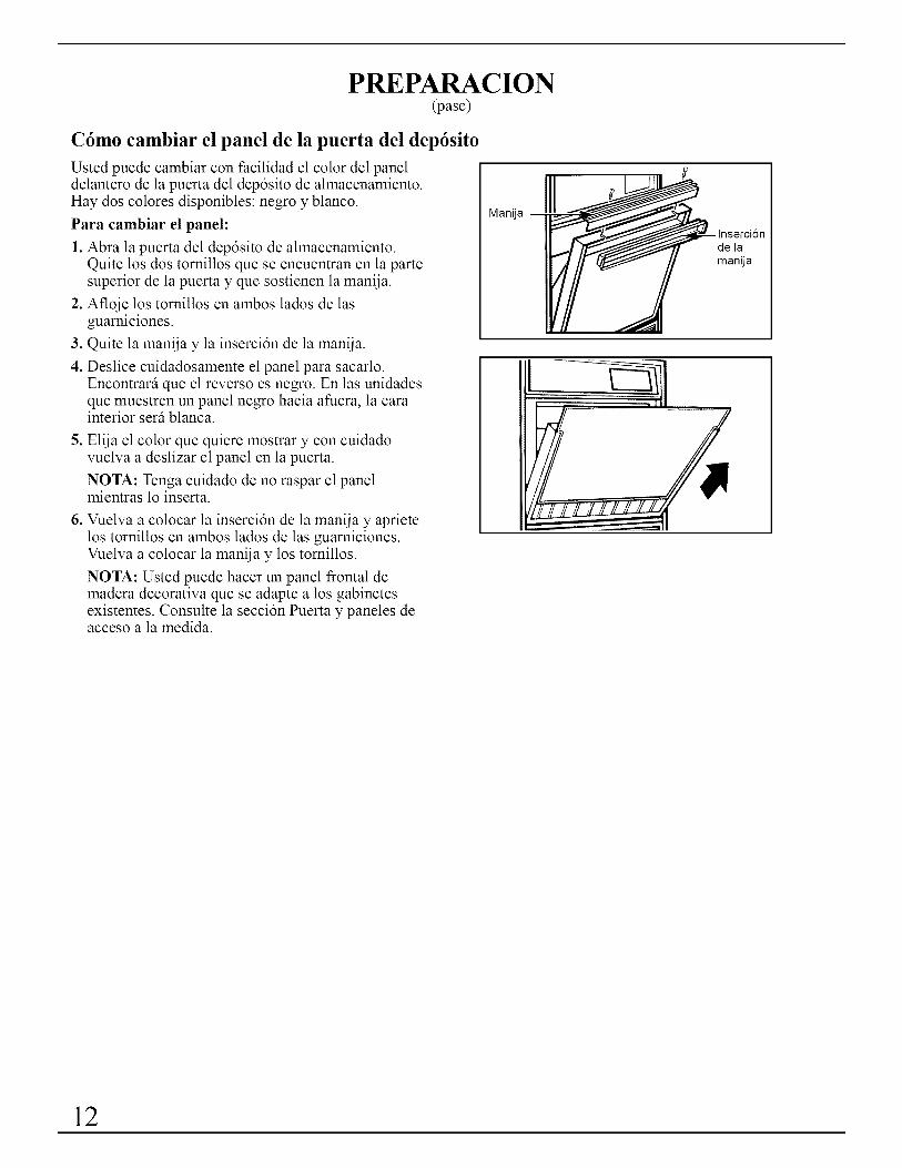
C6mo cambiar el panel de la puerta del dep6sito
Usted puede cambiar con facilidad el color del paneldelantero de la puerta del depdsito de almacenamiento.Hay dos colores disponibles: negro y blanco.
Para cambiar el panel:
1. Abra la puerta del depdsito de almacenamiento.Quite los dos tomillos que se encuentran en la partesuperior de la puerta y que sostienen la manija.
2. Afloje los tomillos en ambos lados de lasguamiciones.
3. Quite la manija y la insercidn de la manija.
4. Deslice cuidadosamente el panel para sacarlo.Encontrarfi que el reverso es negro. En las unidadesque muestren un panel negro hacia afuera, la carainterior serfi blanca.
5. Elija el color que quiere mostrar y con cuidadovuelva a deslizar el panel en la puerta.
NOTA: Tenga cuidado de no raspar el panelmientras lo inserta.
6. Vuelva a colocar la insercidn de la manija y aprietelos tornillos en ambos lados de las guarniciones.Vuelva a colocar la manija y los tomillos.
NOTA: Usted puede hacer un panel frontal demadera decorativa que se adapte a los gabinetesexistentes. Consulte la seccidn Puerta y paneles deacceso a la medida.
Manija
de lamanija
1
12
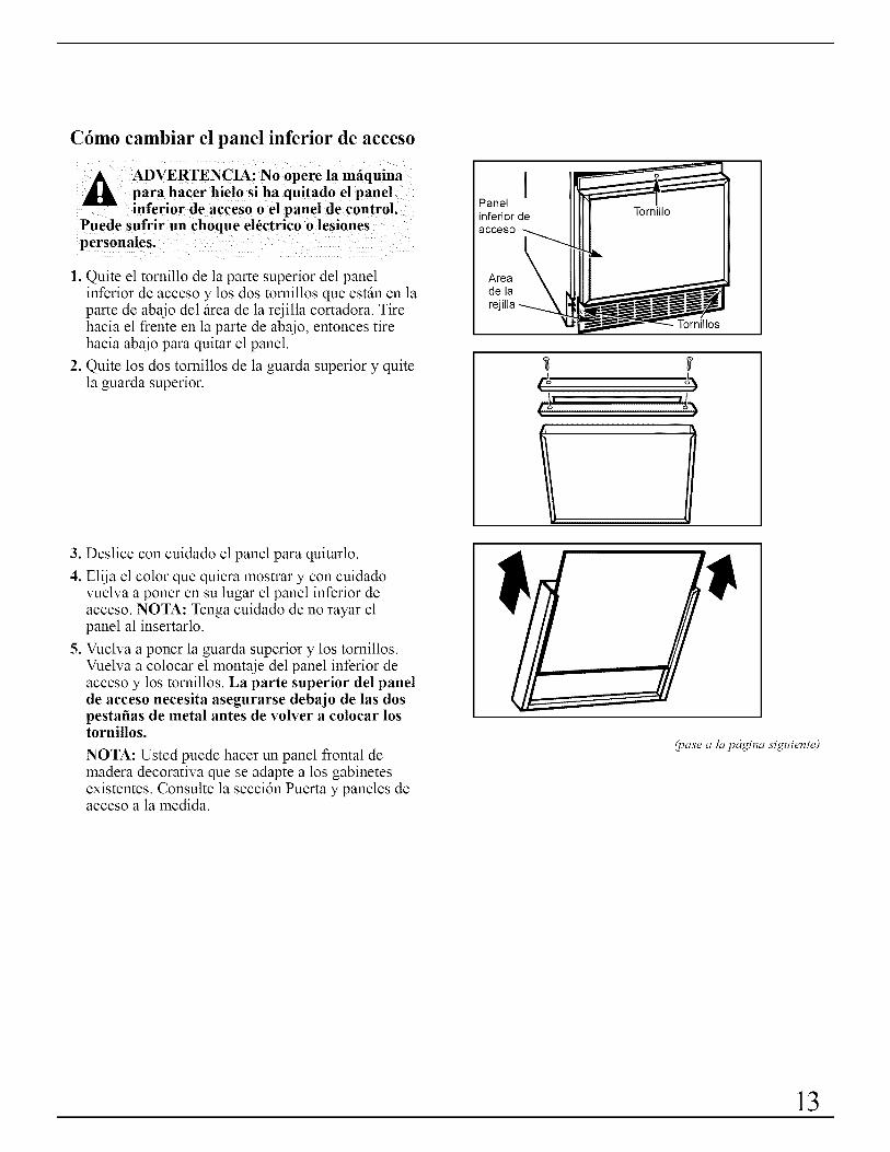
C6mo cambiar el panel inferior de acceso
A ADVERTENCIA: No opere la mfiquinapara hacer hielo si ha quitado el panel
_l inferior de acceso o el panel de control.Puede sufrir un choque el6ctrico o lesionespersonales.
1. Quite el tornillo de la parte superior del panelinferior de acceso y los dos tornillos que estfin en laparte de abaio del firea de la reiilla cortadora. Tirehacia el frente en la parte de abaio, entonces tirehacia abaio para quitar el panel.
2. Quite los dos tornillos de la guarda superior y quitela guarda superior.
3. Deslice con cuidado el panel para quitarlo.
4. Elija el color que quiera mostrar y con cuidadovuelva a poner en su lugar el panel inferior deacceso. NOTA: Tenga cuidado de no rayar elpanel al insertarlo.
5. Vuelva a poner la guarda superior y los tomillos.Vuelva a colocar el montaje del panel inferior deacceso y los tornillos. La parte superior del panelde acceso necesita asegurarse debajo de las dospestafias de metal antes de volver a colocar lostornillos.
NOTA: Usted puede hacer un panel frontal demadera decorativa que se adapte a los gabinetesexistentes. Consulte la secci6n Puerta y paneles deacceso a la medida.
IPanelinferior deacceso
Areade la
Tornillos
I
(pase a la pc'lgina si_tiente)
13
PUERTA Y PANELES DE ACCESO A LA MEDIDA
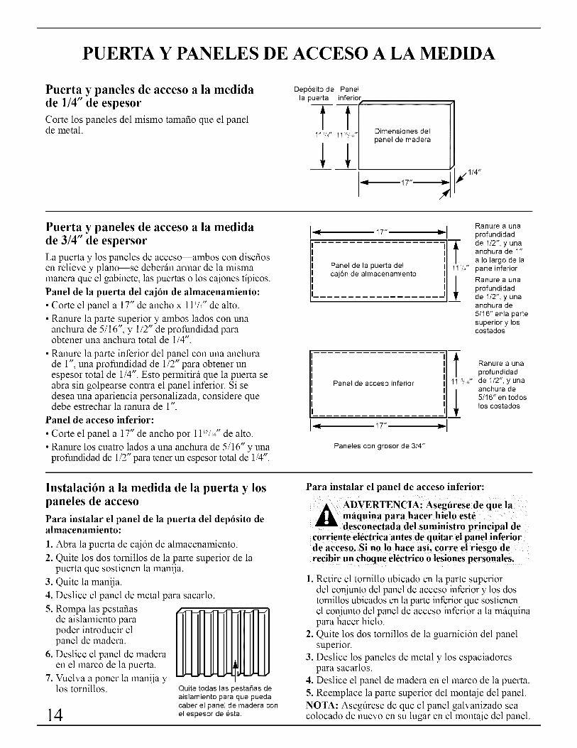
Puerta y paneles de acceso a la medidade 1/4" de espesor
Corte los paneles del mismo tamafio que el panelde metal.
Dep6sito de Panella puerta inferior
Tt11 VY' 11 WEJ'
Dimensiones delpanel de madera
17"_1€/1!4"
4'
Puerta y paneles de acceso a la medidade 3/4" de espersor
La puerta y los paneles de acceso--ambos con disefiosen relieve y plano--se deberfin armar de la mismamanera que el gabinete, las puertas o los cajones tipicos.
Panel de la puerta del cajdn de almacenamiento:
• Corte el panel a 17" de ancho x 11t/4" de alto.
• Ranure la parte superior y ambos lados con unaanchura de 5/16", y 1/2" de profundidad paraobtener una anchura total de 1/4".
• Ranure la parte inferior del panel con una anchurade 1", una profundidad de 1/2" para obtener unespesor total de 1/4". Esto permitirfi que la puerta seabra sin golpearse contra el panel inferior. Si sedesea una apariencia personalizada, considere quedebe estrechar la ranura de 1".
Panel de acceso inferior:
• Corte el panel a 17" de ancho por llWl/' de alto.
• Ranure los cuatro lados a una anchura de 5/16" y unaprofundidad de 1/2" para tener un espesor total de 1/4".
17"
Panel de la puerta delcaj6n de almacenamiento
Panel de acceso inferior
17"
Paneles con grosor de 3/4"
-f11V4"
!
Ranure a una
profundidadde 1/2", y unaanchura de 1"
a Io largo de laparte inferiorRanure a una
profundidadde 1/2", y unaanchura de
5/16" enla partesuperior y loscostados
Ranure a unaprofundidadde 1/2", y unaanchura de5/16" en todoslos costados
Instalaci6n a la medida de la puerta y lospaneles de acceso
Para instalar el panel de la puerta del dep6sito dealmacenamiento:
1. Abra la puerta de cajdn de almacenamiento.
2. Quite los dos tornillos de la parte superior de lapuerta que sostienen la manija.
3. Quite la manija.
4. Deslice el panel de metal para sacarlo.
5. Rompa las pestafiasde aislamiento parapoder introducir elpanel de madera.
6. Deslice el panel de maderaen el marco de la puerta.
7. Vuelva a poner la manija ylos tornillos.
14
Quite todas las pestafias deaislamiento para que puedacaber el panel de madera conel espesor de esta.
Para instalar el panel de acceso inferior:
A DVERTENCIA: Asegfirese de que lamfiquina para hacer hielo est_desconectada del suministro principal de
corriente el_ctrica antes de quitar el panel inferiorde acceso. Si no lo hace asi, corre el riesgo derecibir un choque el_ctrico o lesiones personales.
1. Retire el tornillo ubicado en la parte superiordel coniunto del panel de acceso inferior y los dostomillos ubicados en la parte inferior que sostienenel coniunto del panel de acceso inferior a la mfiquinapara hacer hielo.
2. Quite los dos tornillos de la guarnicidn del panelsuperior.
3. Deslice los paneles de metal y los espaciadorespara sacarlos.
4. Deslice el panel de madera en el marco de la puerta.
5. Reemplace la parte superior del montaie del panel.
NOTA: Asegfirese de que el panel galvanizado seacolocado de nuevo en su lugar en el montaie del panel.
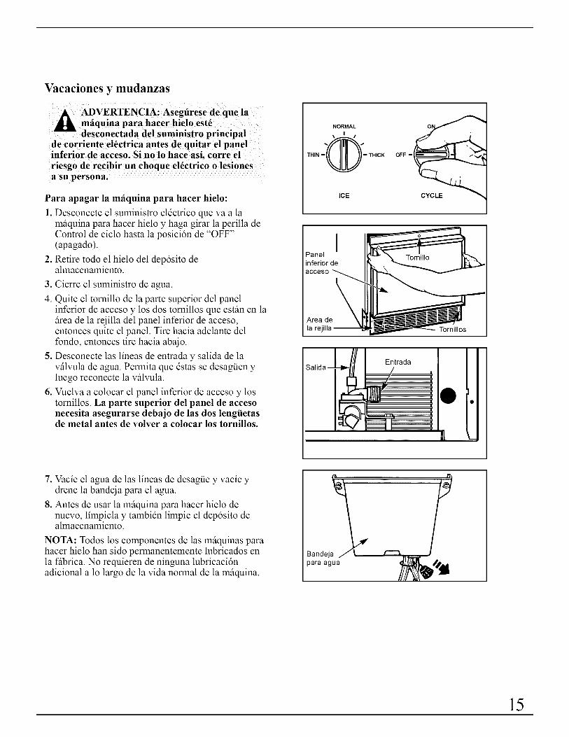
Vacaciones y mudanzas
A ADVERTENCIA: Asegfirese de que lamfiquina para hacer hielo est_desconectada del suministro principal
de corriente el_ctrica antes de quitar el panelinferior de acceso. Si no lo hace asi, corre el
riesgo de recibir un choque el_ctrico o lesionesa su persona.
Para apagar la mfiquina para hacer hielo:
1. Desconecte el suministro eldctrico que va a lamfiquina para hacer hielo y haga girar la perilla deControl de ciclo hasta la posicidn de "OFF"(apagado).
2. Retire todo el hielo del depdsito dealmacenamiento.
3. Cierre el suministro de agua.
4. Quite el tornillo de la parte superior del panelinferior de acceso y los dos tomillos que estfin en lafirea de la reiilla del panel inferior de acceso,entonces quite el panel. Tire hacia adelante delfondo, entonces tire hacia abaio.
5. Desconecte las lineas de entrada y salida de lavfilvula de agua. Permita que dstas se desagiJen yluego reconecte la vfilvula.
6. Vuelva a colocar el panel inferior de acceso y lostornillos. La parte superior del panel de accesonecesita asegurarse debajo de las dos lengiietasde metal antes de volver a colocar los tornillos.
NORMAL
\ I /
0THIN - - THICK
ICE
OFF - "_
CYCLE
Panelinferior deacceso
\Area dela rej Tornillos
Entrada
I
L_
7. Vacie el agua de las lineas de desagiJe y vacie ydrene la bandeia para el agua.
8. Antes de usar la mfiquina para hacer hielo denuevo, limpiela y tambidn limpie el depdsito dealmacenamiento.
NOTA: Todos los componentes de las mfiquinas parahacer hielo han sido permanentemente lubricados enla ffibrica. No requieren de ninguna lubricacidnadicional a lo largo de la vida normal de la mfiquina.
Bandejapara agua
15

INSTALACION INDEPENDIENTE
Para el instalador
Cuando se instala esta mfiquina para hacer hielo de manera independiente(no debajo de un mostrador) recomendamos fuertemente que las esquinasposteriores del fondo de la mfiquina para hacer hielo se suieten al suelopara evitar que se vuelque por casualidad.
INSTRUCCIONES PARA LA INSTALACIONIMPORTANTE...Leer detenidamente
Para el electricista--Requerimientos el6ctricos
Se requiere un suministro eldctrico de 115 voltios, 60 Hz y 15 amperes. Serecomienda que estd conectado a un fusible de retardo o a un interruptor decircuito. Se recomienda la existencia de un circuito separado que sirra s61oa este aparato. NO use un cable de extensidn.
ESTE APARATO DEBE ESTAR CONECTADO A TIERRA.
M_todos que se recomiendan para conectar a tierra
BAJO NINGUNA CIRCUNSTANCIA QUITELA PATA DE CONEXION A TIERRA DE
LA CLAVIJA QUE SE ENCUENTRA EN ELEXTREMO DEL CABLE DE SUMINISTROELECTRICO.
Toma de corriente
de pared aterrizadade 3 patas
Por su seguridad personal, este aparato debe estarconectado a tierra de la manera correcta.
Este aparato estfi equipado con un cable de suministroeldctrico que tiene una clavija conectora de tres pataspara aterrizar la mfiquina. Para evitar al mfiximo elriesgo de choque eldctrico la clavija debe conectarseen una toma de corriente aterrizada para clavija de trespatas, y cuya conexidn a tierra cumpla con el CddigoNacional Eldctrico y los cddigos y ordenanzas locales.Si no cuenta con una toma de corriente de este tipo, esresponsabilidad y obligacidn personal del cliente hacerque un electricista calificado instale una toma decorriente correctamente aterrizada, de tres patas.
Clavija de 3 patascon pata paraconexi6n a tierra
Cable de suministroelectrico
16
Vista del lado derecho
3/4" -_
Linea decompresi6nde 1/4" de <_diametroexterior que
237/8"
I
Valvula desolenoidede admisi6n
Vista posterior
4- 17%" --i,.-
34W="se conecta de aguaa la valvula _ / Ide agua _ _/'...... ,' I
-_ £j ',¢ I1 - "it, 33/4"_ -_- I .
7/_ 1_,-÷ ........ i_-_L.[ 1_÷_.J"Doble ta linea de suministro 2/='-_-,
Figura 1 de agua para conectarta a laconexi6n de la valvula de agua
Tubo de desagOede 4" de largo y5/8" de diametro
interior--correhacia el drenajeabierto
-- 11/4"Min.
_--l__,l I_
9,,_I Agujero para lalinea de suministro
3/4" _ deagua
_//_ "_x
-- /' i t
_ . ,%+_--90o| 90o
I/ '=341/Z" 9" _;_ j
/I Max.{'21/
/ 41/Z"hasta_-- / I la linea k, _i
_/___L delcentro _
/, 18------_
Figure 2
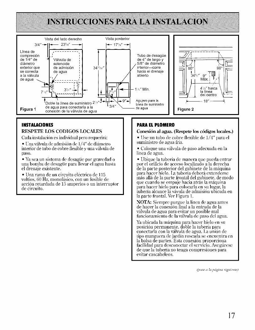
INSTALACIONES
RESPETE LOS CODIGOS LOCALES
Cada instalacion es individual pero requerir_i:
• Una vidvula de adrnision de 1/4" de di__rnetrointerior de tubo de cobre flexible y una vidvula depaso.
• Ya sea un sistema de desagiie por gravedad ouna bomba de desagiie para llevar el agua hastael drenaje existente.• Una rarna de un circuito el6ctrico de 115voltios, 60 Hz, monofasico, con un fusible deacci6n retardada de 15 amperios o un interruptorde circuito.
PAPAELPLOMERO
Conexi6n al agua. (Respete los c6digos locales.)
• Use un tubo de cobre flexible de 1/4" para elsuministro de agua fria.
• Coloque una valvula de paso adecuada en lalinea de agua.
• Ubique la tuberia de manera que pueda entrarpor el orificio de acceso localizado a la derechade la parte posterior del gabinete de la maquinapara hacer hielo. La tuberia debera extendersemas alla de la parte frontal del gabinete, de modoque cuando se empuje hacia atras la maquinapara hacer hielo para colocarla en su lugar, latuberia alcance la vavula de admisi6n ubicada enla parte frontal. Ver Figura 1.
NOTA: Siempre purgue la linea de agua antesde hacer la conexi6n final a la entrada de lavalvula de agua para evitar un posible malfuncionamiento de la valvula de paso del agua.
Ya ubicada la maquina para hacer hielo en suposici6n permanente, doble la tuberia paraconectarla con la valvula de agua. La uni6n detipo manguera de jardin roscada se encuentra enla bolsa de partes. Esta conexion proporcionafacilidad para desconectar el servicio. Asegfiresede que la tuberia no tenga compresiones paraevitar cascabeleos.
(pase a la pdgina si_tiente)
17

NIVELACION
• Despu_s de colocar la mS.quina para hacerhielo en posicion, revise para cerciorarse queest_ nivelada de lado a lado y del frente haciaatras.
• Una nivelacion precisa es esencial para unaoperacion adecuada.• La m_.quina para hacer hielo debe estaracufiada para que quede solida lo mismo quenivelada. Las cutlas deben set de un materialduro y permanente como el masonite (maderaaglomerada).• Los est_.ndares de la Fundacion Nacional parala Higiene determinan que este tipo de productodebe quedar sellado al suelo en el riel inferiorpara asi evitar contaminacion por derrames o laentrada de sabandijas. Pot lo tanto,recomendamos que cuando instala la m_.quinapara hacer hielo la asiente en el suelo de acuerdocon esos est_.ndares. Se recomienda un selladorde tipo silicona.
METODOALTERNO
Instale una bomba de desagiie, aprobadapor UL, en la parte trasera de la mfiquinade hacer hielo, si una conexi6n de drenajedirectamente debajo de la salida del tubode drenaje no es disponible.
Especificaciones de la bomba de desagiie:
• Aprobada por UL, con un cord6n elgctrico,aprobado por UL, de 3 alambres con conexi6n atierra de 120 ratios AC (corriente alterna)
• Dimensiones exterior total (maximo): 15" deanchura x 6" de profundidad x 9 1/2" de altura.
• Raz6n del flujo de la bomba (minimo): 24.0galones por hora (0.4 gal6n por minuto) y conaproximadamente un alzamiento de 12'.
• Temperatura de funcionamiento oscila entre55° Fy 110° F (13° Cy43 ° C)
BOMBADE DESAGUE
• Cuando se instala la conexion de drenajedebajo de la m_.quina para hacer hielo, puedeusarse una bomba de desagtie para llevar el aguahasta un drenaje disponible. Use solo un juegode bomba de desagtie aprobado ZDK50 de sudistribuidor.
• Las instrucciones completas de instalacion seincluyen con el juego de bomba de desagtie.
VERIFIQUELAOPERACION• Ponga a funcionar la m_.quina para hacer hielocolocando el interruptor de servicio en "ON"(encendido) y abra la valvula de la linea de agua.• NOTA: Hacia la izquierda es "OFF"(apagado), en el medio es "ON" (encendido) y ala derecha es "CLEAN" (limpiar). En la posicionde "CLEAN" (limpiar) solo la bomba opera.• Revise el ventilador del condensador paraasegurarse de que est+ dando vueltas.• E1agua no entrar_, a la bandeja de agua dela bomba hasta que la placa de congelacion seenfrie y la maquina para hacer hielo entre en unciclo de recolectar el hielo.
• Revise que el flujo de agua sea uniforme sobrela placa de congelacion. La m_.quina para hacerhielo debe estar nivelada para operar de maneracorrecta.
• Revise que el espesor de los cubos de hielo seael deseado y despu_s de 24 horas ajuste esto sies necesario. E1 rendimiento m£ximo de hielo seobtendr_, con un espesor del hielo de 1/2"(1.25 cm) a 5/8" (1.50 cm).
• Reemplace la rejilla.
18

i,ALGUNA PREGUNTA?CONSULTE ESTAS SOLUCIONES
PROBLEMA
LA MAQUINA PARA HACERHIELO NO FLrNCIONA
LA MAQUINA PARA HACERHIELO OPERA PERONO PRODUCE HIELO
LA MAQU1NA PARAHACER HIELO OPERAPERO PRODUCE MUYPOCO HIELO
LA REJILLA NO ESTACORTANDO LAS PLACASDE HIELO
LOS CUBOS DE HIELOTIENEN SABOR PECULIAR
CAUSA POSIBLE
• La perilla de control de ciclo debe estar en la posicion de "ON" (encendido).
• Revise que el cable de corriente estd conectado.
• LRevis6 la caia de fusibles o el interruptor de circuito?
• La temperatura ambiente debe ser mayor que 55 °F. (13 °C.). De otro modo. eltermostato det depdsito puede percibir una temperatura fria en la habitacidn ycerrarse aunque et depdsito no estd lleno de hielo. Tambidn es posible que lamfiquina para hacer hielo pueda no encenderse una vez que se ha apagado.
• La perilla de control de ciclo debe estar en la posicidn de "ON" (encendido).
• Revise si estfi abierta la llave de suministro de agua.
• Si la mfiquina para hacer hielo opera a mils de 2000' (610 m)de altitud o milssobre el nivel det mar. serfi necesario recalibrar tanto et termostato del dep6sitocomo el termostato de grosor del hielo. Vea las Instrucciones de instalaci6n.
• La temperatura de la habitacidn puede ser extremadamente alta. mils de 90 °F.(32 °C.). En este caso es normal que la produccidn de hieto sea baia.
• La suciedad o la petusa pueden estar obstruyendo et flujo de aire a travds detcondensador con rejillas. Necesita limpiar el condensador.
• Revise para ver si la mfiquina para hacer hielo ha acumulado agua en el interiory en el sistema de congelacidn. Limpie si es necesario.
• Revise que et cableado de la rejilla estd bien conectado y de manera segura.
• Puede haber una cantidad muy elevada de minerales en el agua que entra. E1
agua puede necesitar filtrarse o tratarse.
• No almacene ningfin alimento en et depdsito para hielo.
• No se quit6 todo el material de empaque.
Si necesita m_is ayuda...llame sin costo a:GE Answer Center _"_,800.626.2000consumer information service
19
Estaremos Con UstedCon la compra de su nuevo aparato GE recibifft la seguridad de que si alguna vez necesitainformaci6n o asesoria de GE, estaremos a su disposici6n. Todo lo que fiene que hacer esllamar-isin costo! En GE Answer Center se habla espafiol.
GEAnswerCenter®800.828.2000
Cualquiera que sea su pregunta sobre alguno de los grandes aparatos de GE, el smsTiciode informacidn de GE Answer(;enter sera dispuesto a a?al(tar. Usted llama y su pregunta ser;t contestada inmediatamente y con cortesia. Y usted puedellamar a cualquier hora. E1setsTicio de GE Answer (;enter est_ abierto 7 dias a la semana las 24 horas del dia.
Serviciodereparaci6nensuho#ar800-GE-CARES(800432-2737)Un especialista del set_icio al consumidor de GE le proporcionara el sex_icio especializado de reparaci6n,programado a la hora inas conveniente para usted. Muchos centros de sexs_icio al consumidor de GE operados por lacoinpa_-_ia le ofl'ecen sexs_icio h W o ma_-mna o cuando a usted le convenga (7:00 am a 7:00 pm en dias laborables y 9:00am a 2:00 pm los s_bados). Nuestros tdcnicos capacitados por la f_brica conocen su aparato por fllera y pordentro-asi, la inayoria de las reparaciones se hacen en s61o una visita.
ISECTIONA-A
Paraclientesconnecesidadesespeciales...800.828.2000
Si se solicita, GE puedeproporcionar controles Braillepara nuinerosos aparatos, asicomo tin folleto de ayuda en laplaneaci6n de una cocina sinbarreras para personas limitadasen su movilidad. Para adquirirestos articulos, llamar sin costo alteldfbno 800.626.2000.
Los consumidores con impedimentos de oido o dehabla que tienen acceso a TDD o a alg6n teletipoconvencional, llamar a1800-TDD-GEAC (800-833-4322)para solicitar infbrmaci6n o sets_icio.
Contratosdeservicio800-828-2224
Usted puede estar seguro de que el GE Consumer Set_ice estar_ alli a6n despuds de que expire su garantia. Compreusted tin contrato de sm_icio mientras que estd vigente su garantia y recibir_ tin descuento considerable. (;on tincontrato para varios a_5os, usted asegura el sets_icio flmlro a los precios de hoy.
Partesy accesorios800-828-2002
Las personas calificadas para dar servicio a sus propios aparatos pueden solicitar las partes y accesorios necesarios quese les enviar_n directamente a sus hogares. E1 sisteina de refacciones de GE tiene acceso a inas de 47000 partes, y todaslas refacciones originales de GE cuentan con plena garantia. Se aceptan taxjetas VISA, Mastercard y Discover.
Las instrucciones de mantenimiento para el usuario que contiene este folleto cubren procedimientos que puederealizar cualquier usuario. Otro tipo de servicios los deber_i ejecutar exclusivamente personal calificado. Es necesariotener precauci6n, ya que el servicio inadecuado puede ser causa de peligros en la operaci6n.
20

GARANTIADE SU MAQUINA PARA HACER HIELO GE
Engrape aqui la nota de caja o el chequecancelado. Es necesario mostrar la
fecha original de la compra para obtenerservicio bajo garantia.
LO QUE ESTA CUBIERTO GARANTIA COMPLETA POR~
UN ANO
Durante un afio a partir le de lafecha de la compra original leproporcionaremos sin cargoalguno partes y servicio de manode obra en su hogar para reparar oreponer cualquier parte de lamaquina para hacer hieloMonogram que falle a causa dealg_n defecto de fabricaci6n.GARANTIA COMPLETA PORClNCO ANOS
Durante cinco afios a partir de lafecha de la compra original,proporcionaremos sin cargoalguno partes y servicio de manode obra en su hogar para repararo reponer cualquier parte delsistema sellado de la maquinapara hacer hielo (el compresor,el condensador, el evaporador ytodas las tuberias de conexi6n)que falle a causa de alg_n defectode fabricaci6n.
Esta garantia se extiende alcomprador original y a cualquierpropietario subsecuente potproductos comprados para usonormal en el hogar en los 48estados del continente, Hawai yWashington D.C. En Alaska valdrala misma garantia pero con laLIMITACION de que el propietariopagara el costo del embarque altaller de servicio o los viaticos delt6cnico de servicio hasta su hogar.
Todos los servicios de garantia seranproporcionados pot nuestros centrosde servicio de fabrica (FactoryService) o pot los t6cnicosautorizados de Atenci6n al Cliente(Customer Care ®) durante lashoras laborables normales.
Si su aparato necesitara serviciodurante el periodo de garantia oposteriormente, Ilame a800-GE-CARES (800-432-2737).
LO QUE NO ESTACUBIERTO
Viajes de servicio a su hogarpara mostrar c6mo se usa elproducto.
Lea el material de Use ycuidado. Si a_n tuviera algunapregunta sobre c6mo operar elproducto, favor de contactar anuestro representante o a nuestraoficina de Asuntos del consumidor(Consumer Affairs Office) en ladirecci6n que aparece abajo oIlam6 sin cargo a:GE Answer Center ¢800.626.2000consumer information service
• Instalaci6n inadecuada.
Si usted tiene algQn problemade instalaci6n, contacte a nuestrorepresentante o instalador.Usted es responsable deproporcionar las instalacionesadecuadas de electricidad,plomeria y otras conexiones.
• Reemplazo de fusibles del hogaro eliminaci6n de cortocircuitos.
• Uso de un juego de bomba dedesagQe no aprobado.
• Fallas del aparato si 6ste seusara para otros prop6sitos quelos propuestos o se usara parafines comerciales.
• Dafios al producto causados poraccidentes, fuego, inundacioneso cualquier fuerza de causamayor.
• P6rdida de alimentos a causade averias.
LA EMPRESA QUE OTORGA LAGARANTIA NO ESRESPONSABLE DE DANOSCONSECUENTES.
Algunos estados no permiten la exclusi6n o la limitaci6n de dafios incidentales o consecuentes, de manera que la limitaci6n o exclusi6n mencionadano seria valida para usted. Esta garantia le proporciona derechos legales especificos y usted podra tener otros derechos masque varian de estado aestado. Para saber que derechos legales tiene en su estado, consulte a la oficina local de derechos del consumidor o a la procuraduria de su estado.
Empresa que otorga la garantia: General Electric CompanySi necesitara asesoria con respecto a esta garantia, escriba a:
Manager--Consumer Affairs, GE Appliances, Louisville, KY 40225
2180919
Part No. 162D7745P002Pub. No. 49-6857
ZDIB50, ZDIW50
Impreso en los Estados Unidos
2!

NOTAS
22