usda forest service apparatus body only specification … · usda forest service . apparatus body...
TRANSCRIPT

USDA FOREST SERVICE
APPARATUS BODY ONLY
SPECIFICATION
TYPE 6 FIRE APPARATUS
MODEL 643U
MAY 2013
Model 643U Body Only Supersedes August 2011
1
USDA Forest Service
Specification: Type 6 Fire Apparatus, Model 643U Specification Type: Apparatus Body Only Issue Date: May 2013
Table of Contents
Topic Page Title Page .........................................................................................................................................1 Table of Contents .............................................................................................................................2 Record of Revisions .........................................................................................................................3 General .............................................................................................................................................4 Chassis Electrical Requirements .....................................................................................................5 Traffic Warning Systems ..................................................................................................................8 Chassis Additions and Modifications .............................................................................................10 Apparatus Body Description ..........................................................................................................13 Pump and Plumbing ......................................................................................................................22 Valves, Controls, Gauges & Plumbing Requirements ..................................................................25 Water Tank .....................................................................................................................................30 Body Electrical Requirements .......................................................................................................32 Electrical System Performance Test, Low-Voltage .......................................................................34 Apparatus Finish ............................................................................................................................36 Equipment ......................................................................................................................................38 Warranty Provisions .......................................................................................................................39 Standard Vehicle Marking..............................................................................................................40
Model 643U Body Only Supersedes August 2011
2

RECORD OF REVISIONS
Date Revision Summary April 2009 Initial Release August 2009 Revision March 2010 Revision February 2011 Revision August 2011 Revision May 2013 Added Table of Contents Added Record of Revisions Clarified radio pre-wire requirements
Deleted green aviation light from light bar Clarified that front bumper bolt-on brush guards are not acceptable Deleted mobile attack bracket requirement Refined chassis component (skid plate) requirements Clarified grab handle requirements Added requirement for flammable material storage warning label Increased number of shelves from eight to nine
Added shelf to passenger side forward compartment Deleted vent from passenger’s side lower aft compartment Added vent to door face and rear wall of driver’s side aft compartment Revised auxiliary fire pump specifications Revised optional pump specifications Revised pump panel requirements Added heading for “Valves, Controls, Gauges & Plumbing Requirements” Changed discharge pressure gauge from 600 psi to 400 psi
Clarified that foam system cannot be mounted in a storage compartment Revised standard vehicle markings
Revised wheel chock requirements and deleted requirement for lanyard Deleted requirement for swivel hooks
Revised warranty to ten (10) years Added standard vehicle marking drawing
Model 643U Body Only Supersedes August 2011
3
GENERAL The utility body described in this specification shall be mounted on Government furnished cab and chassis. Government furnished cab and chassis shall be picked up by the apparatus manufacturer at designated locations. The apparatus manufacturer shall be liable for all loss and damage to Government furnished cab and chassis until completion and final acceptance of work and returned to the Government. The completed apparatus described in this specification shall be compliant with the requirements of NFPA 1906, latest edition, except where noted. TILT TEST The apparatus shall be tilted to 30° minimum before lifting a tire or tire set when tested at the estimated in-service weight in accordance with NFPA 1906. BRAND NAME OR EQUIVALENT PRODUCTS Products equivalent to the brand name components specified herein shall be approved in writing by the government prior to contract award and documented in the resultant contract. APPARATUS BODY MATERIAL The apparatus body shall be fabricated from bonded and molded fiber reinforced composite, or galvanneal treated steel. AUXILIARY PUMP The auxiliary pump for this apparatus shall be specified by the Government.
Model 643U Body Only Supersedes August 2011
4

CHASSIS ELECTRICAL REQUIREMENTS CHASSIS ELECTRICAL ADDITIONAL EQUIPMENT AND MODIFICATIONS The apparatus chassis shall be equipped with a heavy-duty 12 volt direct current (VDC) negative ground electrical system. The electrical system shall include all parts, components, switches, relays, wiring, and other devices required to assure complete, consistent and proper operation of the completed apparatus. The electrical system will be fabricated in modules as is the apparatus. The body and chassis will be individually wired as independent modules and connected as a completed unit at the final assembly via bulkhead type waterproof electrical connectors located in the body floor adjacent to the electrical compartment. All GXL/SXL wiring for the apparatus body will be within a temperature resistant harness rated at a minimum of 280°F. All wires in each harness must be color and function coded. Wiring will be run along structural rails and tied in a neat and orderly manner. Wiring shall be routed and/or protected to eliminate exposure to moving parts or debris. Wiring passing through compartments shall be protected from tears, abrasions, and cuts caused by loose item moving in the compartment space. All lights required to comply with Federal Government Codes for vehicles of this size and design shall be provided and installed. These lights shall include headlamps and front turn signals with hazard switch, cab marker and clearance lights, back up lights, stop-turn-tail and license plate lights. All switches for the warning lights and other electrical equipment shall be mounted on a separate switch panel located in the cab on a master electrical console mounted between the two front seats. The switches shall be functionally laid out, properly identified, and shall be located within easy reach of both the driver and the officer. The warning light system shall have a “master” switch, which shall allow for the pre-selection of all warning lights. All switches shall be of a heavy duty design. The following additional electrical equipment shall be installed on, and modifications performed to, the specified cab and chassis by the apparatus builder: MULTIPLEX SYSTEM A multiplexed solid state management system for controlling the electrical system devices shall be provided. The system shall be fully programmable, and capable of performing load management functions, system monitoring and reporting. All electrical circuits and wiring shall be rated at 125% of the maximum load being imposed. Hale Class 1 ES-Key, Hale Class 1 Supernode, and Welden V-MUX multiplexing systems meet this requirement. MASTER BODY DISCONNECT SWITCH One (1) master body disconnect switch shall be provided in the cab. The switch shall be rated for 175 amps continuous duty and 800 amps intermittent duty. The switch shall be labeled “ON/OFF” and shall be located on the floorboard to the left side of the driver’s seat. It shall be placed as far aft as possible to prevent accidental actuation. The exposed terminals shall be protected from damage and inadvertent contact. When in the “OFF” position, all electrical power to the apparatus fire package shall be off. Power to the chassis shall remain separate from this switch. A Cole Hersee, Model #M-2484-16, with Model #82065 switch plate “ON/OFF” label meets this requirement. BATTERY ON INDICATOR LIGHT One (1) “Battery On” indicator light, with a green lens, shall be provided on the cab center console, located forward on the left side. This light shall illuminate when the battery switch is turned to the “ON” position and the brightness shall dim automatically via multiplexing system when the chassis headlights are turned on.
Model 643U Body Only Supersedes August 2011
5
JUNCTION BOX An electrical junction box for all apparatus modules, connections, relays, circuit breakers, etc. shall be located under the rear seat. All connection points shall be labeled according to function. Wire length within the box shall be sufficient to allow a minimum of two (2) inches of slack to allow for secure connections and ease of service. All wire shall be installed in an organized fashion. The junction box shall be constructed from black powder coated stainless steel with a hinged door and a spring loaded push-button style latch. BULKHEAD CONNECTIONS All apparatus body wiring either entering or exiting the cab shall be in a harness configuration and pass through a centralized location as close to the interior electrical junction box as possible. The harness(s) shall terminate at the point of the cab entry/exit with a hermetic bulkhead connector(s), designed to facilitate in the separation of the cab/chassis/apparatus body. A Pacific Aerospace and Electronics (PA&E) bulkhead connector or equivalent shall be installed. PERIMETER LIGHTING Ten (10) 4” clear LED lights shall be provided around the vehicle’s perimeter. The lights shall be activated when either the “Perimeter Lights” switch is activated on the center console, when a cab door is open, or when the vehicle is placed in “blocking mode.” The vehicle is in blocking mode when the vehicle transmission is in “park” with the parking brake set and the emergency master switch turned on with the forward facing takedown lights off. The perimeter lighting “OFF” delay shall be synchronized with the chassis exterior courtesy lighting delay. Perimeter light locations shall be as follows: Two (2) lights shall be provided under the apparatus front bumper. Two (2) lights shall be provided facing forward on bulkhead of body, one (1) on each side. Four (4) lights shall be provided under the apparatus body, one (1) forward and one (1) aft of the rear wheel wells, both sides of the body. The lights shall be housed within an enclosure sufficient to protect from damage within the compartments. Two (2) lights shall be provided under the tail board, protected from impact and debris. The lights shall be wired to the “Perimeter Lights” switch located in the cab center console. BACK UP ALARM One (1) solid state back up alarm shall be provided at the rear of the apparatus, protected from impact and debris. The back-up alarm shall be wired to the reverse circuit of the transmission, and shall provide an audible alarm to the rear of the apparatus when reverse gear is selected. The alarm shall have a volume of 87 to 112 dBA while in operation. MAP LIGHT One (1) flexible goose neck map light shall be provided on the officer’s side of the cab center console. The switch for the map light shall be located on the light and shall include a diffuser to prevent glare at night. ANTENNA One (1) antenna base shall be supplied and mounted on the cab roof as specified. The antenna cable Model 643U Body Only Supersedes August 2011
6

shall be routed to the cab interior, terminating at location of radio mounting bracket. RADIO PRE-WIRE The chassis cab interior shall be wired with battery power, battery ground, switched power, and radio rebroadcast wires to the siren or PA, and labeled to simplify USFS radio installation. The wiring shall allow the radio to be wired “hot” so the radio is powered with the master body disconnect switch turned off. The radio shall occupy the second forward, angled, position in the cab center console. Exposed positive terminals shall be covered by a protective boot or otherwise protected from inadvertent contact.
Model 643U Body Only Supersedes August 2011
7
TRAFFIC WARNING SYSTEMS The following traffic warning systems shall be provided and installed on the completed apparatus by the apparatus builder: ELECTRONIC SIREN One (1) 100/200 Watt full function electronic siren controller shall be provided. The siren control head shall have electronic air horn, public address mode, wired microphone and contain electronic siren tones of wail, yelp and Hi-Lo. The control head shall be mounted in the rearward position of the cab center console. A Federal Signal model PA300-MSC electronic siren meets this requirement. SPEAKER One (1) 100 watt siren speaker shall be provided and installed in a protected forward facing location. The wiring for the speaker shall be routed to the electronic siren controller. A Federal Signal model MS100 siren speaker meets this requirement. FORWARD UPPER ZONE A/B/D LIGHT BAR One (1) LED light bar shall be provided and installed on the forward leading edge of the rear cab protection rack, facing forward. The light bar shall be 60" wide, and shall contain the following modules: Two (2) corner position, forward facing , red flashing modules with clear lens. Four (4) outboard position, forward facing, red flashing modules with red lens. Two (2) inboard position, forward facing, red steady burn modules with red lens. Two (2) center position, forward facing, white “takedown” flashing strobe modules with clear lens. Two (2) corner position, rear facing, red flashing modules with clear lens. Two (2) outboard position, rear facing, red flashing modules with red lens. The light bar shall be wired to the “Emergency Master” switch located on the cab center console. The two (2) forward facing “takedown” modules shall be interlocked with the application of the emergency brake, placing the apparatus in blocking mode and disabling the modules as such. A Whelen brand Edge Ultra Freedom light bar or equivalent shall be installed. LOWER ZONE A WARNING LIGHTS Two (2) red LED warning lights, with mounting flanges, shall be provided at on the front of the apparatus, forward facing, one (1) per side, in the brush guard. The lights shall be wired to the “Emergency Master” switch located on the cab center console. A Whelen brand, 500 Series red LED flasher or equivalent shall be installed. FORWARD ZONE B/D WARNING LIGHTS Two (2) red LED warning lights, with mounting flanges, shall be provided on the front corners of the apparatus chassis, side facing, one (1) per side The lights shall be programmed in a triple flash mode. The lights shall be wired to the “Emergency Master” switch located on the cab center console. A Whelen brand, 400 Series red LED flasher or equivalent shall be installed. AFT LOWER ZONE C WARNING LIGHTS Two (2) amber LED warning lights, with mounting flanges, shall be provided on the lower rear of the Model 643U Body Only Supersedes August 2011
8

apparatus, rear facing, one (1) each side. The lights shall be located in the bottom position of a four-position bezel at the rear of the body with the DOT lights. The lights shall be wired to the “Emergency Master” switch located on the cab center console. A Whelen brand, 700 Series amber LED flasher or equivalent shall be installed.
Model 643U Body Only Supersedes August 2011
9
CHASSIS ADDITIONS AND MODIFICATIONS The following additional equipment shall be installed on, and modifications performed to, the specified cab and chassis by the apparatus manufacturer: APPARATUS FLUID TYPES AND QUANTITIES A permanently-mounted label, showing the recommended fluid types and quantities for the apparatus chassis and associated components, shall be provided in the apparatus cab interior near the driver’s seating position. This label shall list the recommended fluid types and quantities for the following components: Chassis Engine Lubricant Chassis Engine Coolant Chassis Power Steering Fluid Chassis Transmission Fluid Chassis Transfer Case Lubricant Chassis Drive Axle Lubricant Pump Gearbox Lubricant Chassis Brake Fluid SEATING CAPACITY A warning label, listing the seating capacity of the completed apparatus, shall be provided in the apparatus cab interior. This label shall be located so that it is visible from all seating positions. This apparatus shall have a seating capacity of two (2) personnel in front, and three (3) personnel in the rear for a total seating capacity of five (5). SEATING The center portion of the 40/20/40 split bench seat shall be removed to accommodate the installation of the center console. SEAT BELT WARNING A warning label, stating: "DANGER- Personnel Must Be Seated And Seat Belts Must Be Fastened While Vehicle Is In Motion Or DEATH OR SERIOUS INJURY MAY RESULT,” shall be provided in the apparatus cab interior. This label shall be located so that it is visible from all seating positions. VEHICLE HEIGHT WARNING A warning label, listing the overall height, length and GVWR of the completed apparatus, shall be provided in the apparatus cab interior. This label shall be located so that it is visible from the driver’s seating position. FINAL STAGE MANUFACTURER VEHICLE CERTIFICATION A Final Stage Manufacturer vehicle certification label shall be provided and installed in the apparatus cab driver’s door jamb. NOISE HAZARD WARNING A warning label, stating: “WARNING: Noise Hazards Occur During Siren Operation”, shall be provided and installed in the apparatus cab interior. This label shall be located so that it is visible from all Model 643U Body Only Supersedes August 2011
10
seating positions. AIR FILTER EMBER PROTECTION SCREEN WARNING A warning label, stating: “This apparatus is equipped with an air filter ember protection screen; routine inspection is required” shall be provided and installed in the apparatus cab interior. This label shall be located so that it is visible from the driver’s seating position. “DO NOT MOVE APPARATUS” WARNING One (1) surface-mounted red LED light shall be provided in the center cab console, at the top, or most forward position. The light shall flash whenever a compartment door is open and the parking brake is released. The light shall be wired directly into the door ajar switch and hazard circuit. The hazard warning light shall be marked with a label stating “DO NOT MOVE APPARATUS WHEN LIGHT IS ON.” CAB CONSOLE The cab shall be equipped with an angled front, form-fitted control console located between the front driver's and officer's seats. This console shall be sized to accommodate the installation of a switch panel for the control of the emergency and general illumination lighting, siren controller, traffic advisor control head, and customer-mounted radios. The switch panel shall consist of an eight (8) switch multiplex module with lighted switches. The switch module shall have back lighted identification plates on a non-glare panel surface. The switch panel shall be illuminated whenever the master switch is in the “ON” position. Panel light brightness shall dim automatically via the multiplexing system when the chassis headlights are turned on. The cab console shall be fabricated from steel, and painted with a powder-coated black finish. The following controls and switches shall be positioned from forward to aft on the center console as follows: One (1) flexible map light One (1) Push button hose reel rewind switch One (1) faceplate and pre-wiring for Government-mounted radio Two (2) mic clip brackets One (1) switch panel with eight (8) switches One (1) electronic siren controller One (1) traffic advisor control head One (1) 2 position cup holder One (1) 4 position 12V power outlet One (1) 6 inch lockable storage compartment The switch panel shall contain a total of eight (8) switches with pilot lights, numbered and function labeled, configured from left to right as follows: 1- EMERGENCY MASTER 2- HIGH IDLE 3- PERIMETER LIGHTS 4- COMPARTMENT LIGHTS 5- LEFT SCENE 6- REAR SCENE 7- RIGHT SCENE 8- BLANK (Future Use)
Model 643U Body Only Supersedes August 2011
11
FRONT BUMPER AND BRUSH GUARD A heavy duty black powder coated finish bumper and brush guard assembly shall be provided and installed on the front of the apparatus. The complete assembly shall follow the chassis body lines and encompass the perimeter of the chassis front. The complete assembly shall be of such design that the guard will not vibrate, and shall provide a solid mounting area for warning lights, speakers, or other specified equipment. Brush guards bolted onto OEM bumper are not acceptable. REAR BUMPER The rear bumper shall be a minimum of 3” tall by 8” deep and extend across the width of the apparatus body. The bumper shall be fabricated from heavy duty steel tubing, and shall be painted black. The top of the bumper shall be a 4F stainless steel CNC punched and perforated skid resistant surface or NFPA compliant skid resistant treadplate surface. The bumper shall protect the apparatus body. MUD FLAPS One (1) pair of flexible rubber mud flaps shall be provided on both sides of the apparatus body behind the rear wheels. The mud flaps shall not bear company logo. The mud flaps shall extend down far enough to be effective but shall not allow the flaps to become entangled with the rear tires when the apparatus is backing up. EXHAUST SYSTEM The exhaust system shall remain unmodified and as received from the chassis manufacturer. The exhaust system shall be mounted in a horizontal configuration under the passenger’s side of the cab. FUEL HOSE AND ELECTRICAL HARNESS PROTECTION If applicable, any fuel lines or electrical harnesses below the chassis frame rails shall be protected with a fire proof sleeve designed specifically for such purpose. CHASSIS AIR INTAKE EMBER GUARD The chassis air intake shall be protected by an ember guard of 18 Mesh, 0.017 inch wire diameter, and a maximum mesh opening of 0.039 inches. The ember guard shall be sized to fit and located at the intake opening. The screen shall be readily accessible for inspection and maintenance. CABIN AIR EMBER GUARD The cabin air filter shall be protected by an ember guard with a maximum mesh opening of 0.039 inches. The screen shall be located at the point of intake and easily accessible for inspection and maintenance. CHASSIS COMPONENT PROTECTION Aftermarket skid plates shall be installed to protect as a minimum the radiator system and the diesel emissions fluid (DEF) tank. The skid plates shall be constructed of powder-coated 1-inch diameter .095 minimum wall thickness tubular steel. Skid plates shall attach to existing chassis mounting points and shall be readily removable for maintenance.
Model 643U Body Only Supersedes August 2011
12

APPARATUS BODY DESCRIPTION The body shall be designed for fire/rescue service operations only, and shall be constructed to withstand off-road use. The body must be of sufficient design to be capable of withstanding the twisting and abnormal flexing, stresses and other occupational hazards caused by traveling on unimproved mountainous and rangeland roads. No commercially designed bodies intended for use in other vocations or applications are acceptable in quality, construction, design or longevity. The apparatus body shall be fabricated from bonded and molded fiber reinforced composite, or galvanneal treated steel. The installation of hardware parts such as hinges, catches, handles, or knobs shall be accomplished to avoid damaging the hardware or the mounting surface. After fabrication, all parts shall be cleaned of the following: smudges; loose, spattered, or excess welding; metal chips or fillings; or any other foreign material which might detract from the intended operation, function, or appearance of the apparatus or its equipment. This would include any particles which could loosen or become dislodged during the normal expected life of the equipment. Whenever possible, this cleaning shall take place before the parts are assembled. Threaded parts or devices shall show no evidence of cross-threading, mutilation, or detrimental burrs. All screw type and rivet fasteners shall be tight to allow no relative movement between the attached parts. All bolts and screws shall not be tightened in excess of the SAE torque standard established for the grade, screw, and thread type. APPARATUS BODY The entire apparatus body shall be an independent structure and shall be removable in its entirety without the disassembly of any compartments, flooring, or other structural components. The body shall be designed to be approximately as wide as the outside wheel track on the rear axle. This will allow the apparatus to maneuver more easily in off-road environments. The body shall be approximately 95” wide from side to side at the rear of the apparatus. Each compartment shall have ¾” drain located in the rear of the compartment fitted with a easily removable rubber grommet closure. The top of the apparatus shall have a nonskid surface across the entire area. Additionally it shall support, without distortion, a walking person weighing up to 300 lbs. Composite Body The apparatus body shall be fabricated from bonded and molded fiber reinforced composite panels and compartments. The resin shall be thermoset fire retardant, and shall not be subject to distortion or loss of structural integrity at temperatures up to 1000° F. This shall provide a strong, lightweight, corrosion free structure that will withstand extremely high temperatures. All fiberglass used in the construction of the body shall be grade “E” or “S,” and the resin to glass ratio shall be a 30/70 ratio average or higher. The glass reinforced polyester shall not be less than 3/16” thick at any point on the body. Additionally, all coring materials shall have a minimum covering of 1/8” thick glass and resin on either side. All coring for bulkheads, partitions, floors, compartments, and doors shall be either PVC-based, rigid, closed cell structural foam, or composite material. Wood is not acceptable. The apparatus manufacturer shall determine the proper thickness and foam density for each particular application. The fiber composite body shall allow for up to 30° flex off-center without causing body fatigue or component failure. Model 643U Body Only Supersedes August 2011
13

Steel Body The apparatus body shall be fabricated of a minimum of 12 gauge structural steel cross members, providing structural support. Floor shall be constructed of a minimum of 12 gauge galvanneal treated steel. Exterior panels shall be constructed of a minimum of 18 gauge galvanneal treated steel while internal panels shall be constructed of a minimum of 20 gauge galvanneal treated steel. This shall provide a strong, corrosion free structure that will withstand the rigors of wildland fire operations. All materials used in the construction of the body shall be treated with a corrosion preventing coating. The floor width of tank mounting location shall be 54” wide with no wheel well intrusions. BODY FRAME CONSTRUCTION Composite Body The apparatus body and compartments shall be supported with an integrated frame. This frame may consist of a ladder style aluminum frame or an integrated composite assembly bonded to the side compartments with full length mounting sills. In either case, there shall be no more than ¼” of vertical deflection per 256 square inches when 250 lbs. is evenly distributed over 40 square inches. The deck and compartment support design shall be strong enough to support 5000 lbs. in the bed area and 1000 lbs. of equipment in each side compartment assembly (the actual load capability of the completed apparatus may be limited by the GVWR) Steel Body The apparatus body and compartments shall be supported with a frame constructed of commercial grade steel channel or tubular steel members. The frame shall extend under the wheel well areas at the front and rear and shall be attached to the compartments. The cross members in the support system shall be spaced so that there is no more than ¼” of vertical deflection per 256 square inches when 250 lbs. is evenly distributed over 40 square inches. The frame shall be constructed to become an integral portion of the apparatus body. The channel or tubular steel deck and compartment support frames shall be strong enough to support 5000 lbs. in the bed area and 1000 lbs. of equipment in each side compartment (the actual load capability of the completed apparatus may be limited by the GVWR) BODY MOUNTING A spring loaded body mounting system shall be used to mount the body to the chassis. This system shall be designed to allow independent movement between the body frame and the chassis frame protecting the module from the stresses and twisting rendered by the flexing of the chassis frame. As such, the body frame shall not rest on the chassis frame at any point. The mounts shall be pre-engineered for their intended use. All of the mounting hardware (nuts, bolts, washers) required for complete body installation shall be Grade 8 for sizes ½” and smaller, and Grade 5 for sizes larger than ½”. All nuts shall be self-locking style. All mounting brackets shall be painted black. The body front shall be mounted utilizing springer type mounts. The rear body mounts shall be affixed via solid mounts to the chassis frame. Steel Body The center mount shall consist of an 18” long polyurethane spacer mounted mid-length allowing the body frame to rest in a neutral position under full load. Model 643U Body Only Supersedes August 2011
14
VERTICAL SURFACES The entire vertical surfaces at the front and rear bulkhead of the body shall be covered with a minimum 1/8 inch thick polished aluminum tread plate for appearance, wear, and enhanced visibility at night. The treadplate shall be designed so that joints are minimized and shall cover the entire vertical surface area. The treadplate shall also incorporate protection of the outboard corners and serve as corner scuff guards. GRAB HANDLES Three (3) NFPA-compliant chrome-plated grab handle shall be provided and located at the rear of the body: one (1) mounted vertically on the rear-facing surface of the upper compartment, driver’s side, outboard edge, and two (2) 24” long handles mounted horizontally on top of each of the upper compartments, parallel to the outboard edges of the body. REAR STEPS Two (2) NFPA-compliant fold down steps shall be provided and installed at the rear of the apparatus on the left side of the body. The steps shall be fabricated from heavy duty cast aluminum with spring assisted folded hinges. The top of the steps shall be an integral diamond point skid resistant surface that allows water to flow off the step without ice formation in cold weather use. The steps shall be offset bilaterally from each other approximately 12” to facilitate ease of climbing. The vertical distance from the bumper to the first step, between the two steps and from the top step to the top of the apparatus shall not exceed 14 inches. One (1) warning plate shall be affixed to the rear of the apparatus body in a conspicuous location. The warning plate shall read “WARNING: DO NOT RIDE ON REAR STEP WHILE VEHICLE IS IN MOTION. DEATH OR SERIOUS INJURY MAY RESULT.” COMPARTMENTATION All compartment interiors shall be free of exposed electrical harnesses or plumbing components. All compartments shall be as large as possible, as determined by the design of the apparatus. Composite Body All compartment walls and ceilings shall be constructed from bonded and molded fiber reinforced composite. Wood products are not acceptable. All compartments, with the exception of the two (2) upper compartments, shall be attached to the integrated frame. If a ladder style aluminum frame is utilized the compartments shall be be attached to the aluminum tubing superstructure only in order to maintain a truly modular design. Steel Body All compartment walls and ceilings shall be constructed from galvanneal steel. All compartments, with the exception of the two (2) upper compartments, shall be attached to the superstructure only, in order to maintain a truly modular design. Compartment configuration and approximate sizes required are listed below: DRIVER'S SIDE COMPARTMENTS The driver’s side lower module of the apparatus body shall have approximate overall dimensions as specified. It shall consist of three (3) compartments, each with specified approximate clear depth behind the door when the door is shut. Each compartment shall have a “flow through” vent provided to supply air flow and minimize moisture unless designated as fuel storage.
Model 643U Body Only Supersedes August 2011
15
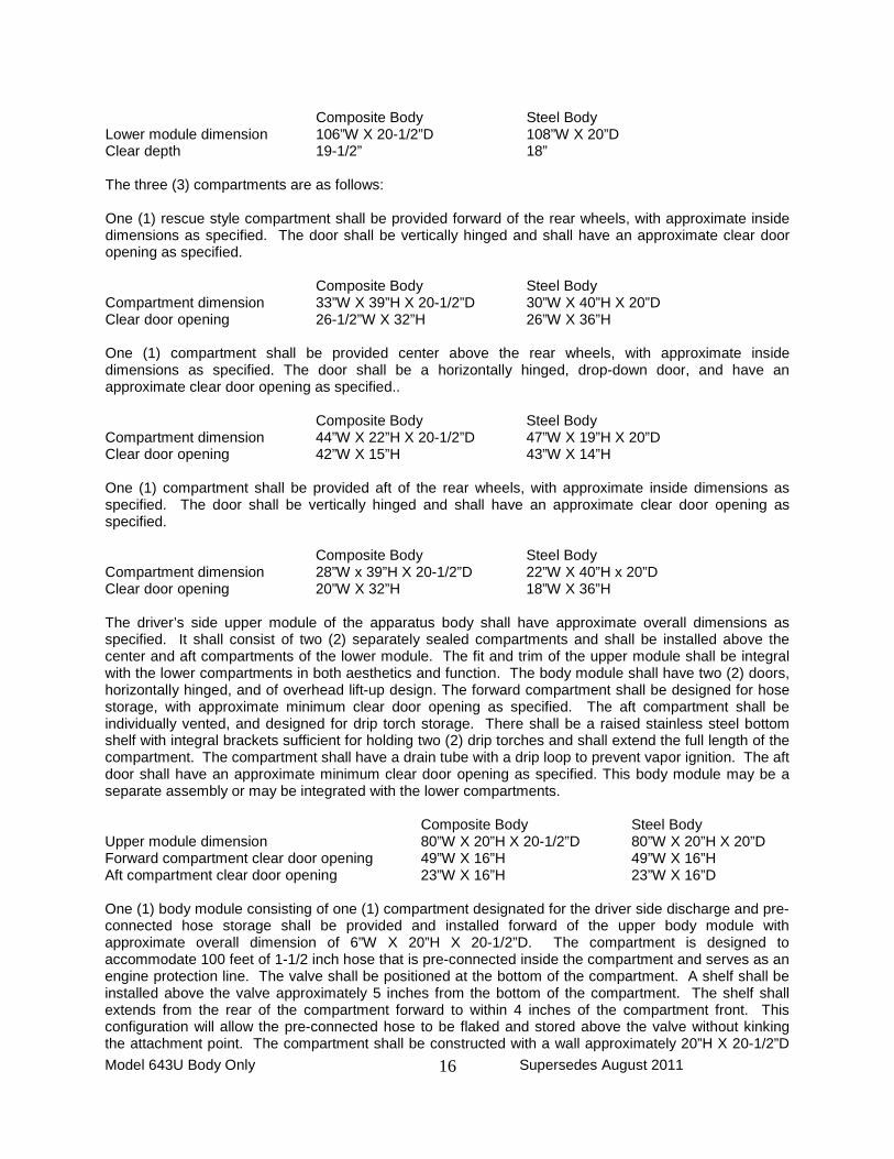
Composite Body Steel Body Lower module dimension 106”W X 20-1/2”D 108”W X 20”D Clear depth 19-1/2” 18” The three (3) compartments are as follows: One (1) rescue style compartment shall be provided forward of the rear wheels, with approximate inside dimensions as specified. The door shall be vertically hinged and shall have an approximate clear door opening as specified. Composite Body Steel Body Compartment dimension 33”W X 39”H X 20-1/2”D 30”W X 40”H X 20”D Clear door opening 26-1/2”W X 32”H 26”W X 36”H One (1) compartment shall be provided center above the rear wheels, with approximate inside dimensions as specified. The door shall be a horizontally hinged, drop-down door, and have an approximate clear door opening as specified.. Composite Body Steel Body Compartment dimension 44”W X 22”H X 20-1/2”D 47”W X 19”H X 20”D Clear door opening 42”W X 15”H 43”W X 14”H One (1) compartment shall be provided aft of the rear wheels, with approximate inside dimensions as specified. The door shall be vertically hinged and shall have an approximate clear door opening as specified. Composite Body Steel Body Compartment dimension 28”W x 39”H X 20-1/2”D 22”W X 40”H x 20”D Clear door opening 20”W X 32”H 18”W X 36”H The driver’s side upper module of the apparatus body shall have approximate overall dimensions as specified. It shall consist of two (2) separately sealed compartments and shall be installed above the center and aft compartments of the lower module. The fit and trim of the upper module shall be integral with the lower compartments in both aesthetics and function. The body module shall have two (2) doors, horizontally hinged, and of overhead lift-up design. The forward compartment shall be designed for hose storage, with approximate minimum clear door opening as specified. The aft compartment shall be individually vented, and designed for drip torch storage. There shall be a raised stainless steel bottom shelf with integral brackets sufficient for holding two (2) drip torches and shall extend the full length of the compartment. The compartment shall have a drain tube with a drip loop to prevent vapor ignition. The aft door shall have an approximate minimum clear door opening as specified. This body module may be a separate assembly or may be integrated with the lower compartments. Composite Body Steel Body Upper module dimension 80”W X 20”H X 20-1/2”D 80”W X 20”H X 20”D Forward compartment clear door opening 49”W X 16”H 49”W X 16”H Aft compartment clear door opening 23”W X 16”H 23”W X 16”D One (1) body module consisting of one (1) compartment designated for the driver side discharge and pre-connected hose storage shall be provided and installed forward of the upper body module with approximate overall dimension of 6”W X 20”H X 20-1/2”D. The compartment is designed to accommodate 100 feet of 1-1/2 inch hose that is pre-connected inside the compartment and serves as an engine protection line. The valve shall be positioned at the bottom of the compartment. A shelf shall be installed above the valve approximately 5 inches from the bottom of the compartment. The shelf shall extends from the rear of the compartment forward to within 4 inches of the compartment front. This configuration will allow the pre-connected hose to be flaked and stored above the valve without kinking the attachment point. The compartment shall be constructed with a wall approximately 20”H X 20-1/2”D Model 643U Body Only Supersedes August 2011
16

adjacent and attached to the upper body module. The opposite wall 20”H X 20-1/2”D wall shall be split vertically approximately 10 inches from the rear of the compartment. The inboard 10 inches of the wall shall be permanently attached to the compartment and the outboard 10 inches permanently attached to the compartment cover. The compartment cover shall be attached by a piano style hinge on the top of the compartment and secured by a non-locking twist-type latch. The configuration of the compartment cover shall allow the lid to be opened straight up, rotated over and rest flat on the back (fixed) portion of the compartment top. This shall allow the operator to reach in and operate the enclosed ball valve unimpeded. The configuration of the cover also allows the ball valve to be repaired without removing the compartment. The compartment shall be constructed from aluminum treadplate. PASSENGER'S SIDE COMPARTMENTS The passenger’s side lower module of the apparatus body shall have approximate overall dimensions as specified. It shall consist of three (3) compartments, each with specified approximate clear depth behind the door when the door is shut. Each compartment shall have a “flow through” vent provided to supply air flow and minimize moisture. Composite Body Steel Body Lower module dimension 106”W X 20-1/2”D 108”W X 20”D Clear depth 19-1/2” 18” The three (3) compartments are as follows: One (1) rescue style compartment shall be provided forward of the rear wheels, with approximate inside dimensions as specified. The door shall be vertically hinged and shall have an approximate clear door opening as specified. Composite Body Steel body Compartment dimension 33”W X 39”H X 20-1/2”D 30”W X 40”H X 20”D Clear door opening 26-1/2”W X 32”H 26”W X 36”H One (1) compartment shall be provided above the rear wheels, with approximate inside dimensions as specified. The compartment shall be accessible from two (2) sides. The passenger’s side door shall be a horizontally hinged, drop-down door, and have an approximate clear door opening as specified. The rear door shall be a horizontally hinged, drop-down door, and have an approximate clear door opening as specified. Composite Body Steel body Compartment dimension 72”W X 22”H X 20-1/2”D 72”W X 19”H X 20”D Passenger side door opening 67”W X 15”H 68”W X 15”H Rear door opening 12-1/2”W X 9-1/2”H 12-1/2”W X 9-1/2”D One (1) compartment shall be provided aft of the rear wheels, below the upper horizontal compartment, with approximate inside dimensions as specified. The door shall be vertically hinged and shall have a clear door opening of approximately 20” W X 11-1/2” H. Composite Body Steel Body Compartment dimension 28”W X 16-1/2”H X 20-1/2”D 26”W X 23”H X 20”D Clear door opening 20”W X 11-1/2”H 22”W X 19”H The passenger’s side upper module of the apparatus body shall have approximate overall dimensions as specified. It shall consist of one (1) compartment installed above the center and aft compartments of the lower module. The fit and trim of the upper module shall be integral with the lower compartments in both aesthetics and function. The compartment shall be accessible from two (2) sides. Two (2) horizontally hinged, overhead lift-up compartment doors shall be located on the passenger’s side. Each shall have an approximate minimum clear door opening as specified. One (1) horizontally hinged, drop-down compartment door shall be located at the rear, and have an approximate minimum clear door opening as Model 643U Body Only Supersedes August 2011
17

specified. This body module may be a separate assembly or may be integrated with the lower compartments. Composite Body Steel Body Upper module dimension 80”W X 20”H X 20-1/2”D 80”W X 20”H X 20”D Passenger’s side clear door opening 35”W X 16”H 35”W X 16”H Rear clear door opening 14”W X 16”H 14”W X 16”H One (1) body module consisting of one (1) compartment designated for the passenger side discharge and pre-connected hose storage shall be provided and installed forward of the upper body module with approximate overall dimension of 6”W X 20”H X 20-1/2”D. The compartment is designed to accommodate 100 feet of 1-1/2 inch hose that is pre-connected inside the compartment and serves as an engine protection line. The valve shall be positioned at the bottom of the compartment. A shelf shall be installed above the valve approximately 5 inches from the bottom of the compartment. The shelf shall extends from the rear of the compartment forward to within 4 inches of the compartment front. This configuration will allow the pre-connected hose to be flaked and stored above the valve without kinking the attachment point. The compartment shall be constructed with a wall approximately 20”H X 20-1/2”D adjacent and attached to the upper body module. The opposite wall 20”H X 20-1/2”D wall shall be split vertically approximately 10 inches from the rear of the compartment. The inboard 10 inches of the wall shall be permanently attached to the compartment and the outboard 10 inches permanently attached to the compartment cover. The compartment cover shall be attached by a piano style hinge on the top of the compartment and secured by a non-locking twist-type latch. The configuration of the compartment cover shall allow the lid to be opened straight up, rotated over and rest flat on the back (fixed) portion of the compartment top. This shall allow the operator to reach in and operate the enclosed ball valve unimpeded. The configuration of the cover also allows the ball valve to be repaired without removing the compartment. The compartment shall be constructed from aluminum treadplate. STORAGE OF FLAMMABLE MATERIALS WARNING A warning label, stating: “DANGER – Do Not Store Flammable Liquid or Combustible Material in this Compartment,” shall be provided on the exterior surface of the passenger side lower aft compartment door. COMPARTMENT DOORS All compartment doors shall be integral in design and recessed into the apparatus body sides, sized to provide easy access to all interior areas of the compartment. All doors shall be consistent in fit and finish with the apparatus body. All doors shall be weatherproof and maintain contact with all points of the weather stripping. Weather stripping shall be bulb type, attached to the opening flange of the compartment opening. Red/white reflector DOT striping shall be installed on the interior surface of all vertically hinged doors. Composite Body The interior surface of the compartment door shall be a gel coat surface of a quality and uniformity equal to that of the exterior surface of the apparatus body. The compartment doors shall be cored with industrial grade closed cell PVC foam, or composite material, of the correct thickness. Steel body Inside door panels shall be painted or powder coated to match exterior body surfaces.
Model 643U Body Only Supersedes August 2011
18
DOOR LATCHES AND HARDWARE Unless where noted, all compartment door latch assemblies shall be installed with threaded fasteners, shall not be welded, and shall be easily removable for servicing or replacement. All latches shall be of a slam-type design, with a single-point latching operation. Matching striker bolts shall be utilized with all latch assemblies. All striker bolts shall have slotted mounting holes, and shall be attached with bolts to captive steel plates in the body structure for strength and ease of adjustment. Welded striker bolts or plates shall not be acceptable. All hardware shall be corrosion resistant and suitable for its intended use. All nuts and bolts shall be stainless steel. Stainless steel nuts shall be the self-locking type. All latch assemblies shall be keyed alike to 1250. All compartment locks for a given engine shall be either vertical or horizontal when locked so that it is visually apparent whether or not a compartment is locked or unlocked. Ten (10) spare keys shall be provided. Composite Body All door latch assemblies shall be of a flush-mount, "D-Handle" two step design, with all external components fabricated from polished stainless steel. Steel Body All door latch assemblies shall be of a flush-mount, paddle-style, with all external components fabricated from polished stainless steel. DOOR HOLD OPEN DEVICES All vertically-hinged, outward-opening compartment doors shall be provided with an over center door check to hold the door in the desired position. The door check shall be attached to the top of the door and fastened to a stainless steel plate bolted into the body and door. All vertically-hinged, outward opening compartment doors shall be capable of being closed with one hand, allowing a free hand to hold equipment or supplies. All horizontally-hinged, drop-down, outward-opening compartment doors shall open to a 90° angle. They shall be supported by a minimum of 3/32” aircraft-type stainless steel cable with stainless steel fork ends. The fork ends shall be attached at each end to a stainless bracket so that the cable can hinge as the door is closed. All horizontally-hinged, overhead lift-up, outward opening compartment doors shall be provided with two (2) extending, gas cylinder type hold open devices, one (1) mounted vertically on each side of the compartment door opening. The pressure rating of the gas cylinders shall be carefully matched to the size and weight of the compartment door, and shall hold the compartment door securely open to a greater than 90° angle without additional support. The gas cylinder hold openers shall dampen the upward movement of the compartment door while opening, and shall permit the closing of the compartment door without the need to release any type of manual locking devices. All horizontally-hinged, overhead lift-up compartment doors shall be capable of being closed with one hand, allowing a free hand to hold equipment or supplies. ADJUSTABLE SHELF CHANNELS Vertically-mounted aluminum Unistrut channels shall be provided and installed in all enclosed body compartments, except passenger’s side lower rear compartment, for the current or future installation of infinitely-adjustable shelving, slide out trays or equipment brackets.
Model 643U Body Only Supersedes August 2011
19

COMPARTMENT SHELVES Nine (9) adjustable shelves shall be provided and installed in the completed body compartments. The shelves shall be 15” in depth and be constructed of fiberglass or aluminum and be capable of supporting 250 lbs. of live load without being damaged or permanently distorted. The shelf locations shall be as follows: Two (2) in the driver’s side compartment forward of the rear wheels One (1) in the driver’s side center compartment. This shelf shall have a reduced height leading edge to facilitate equipment access in a raised position. This shelf shall remain fully adjustable in height. Four (4) in the driver’s side aft compartment One (1) in the passenger’s side compartment forward of the rear wheels. One (1) in the passenger's side upper rear compartment above the rear wheels. The shelf shall run the entire length of the apparatus body transecting compartment #6, approximately 6-1/2” from the top of the compartment. The shelf shall be designed for the storage of hard suction hose sections approximately 8 ft. in length and up to 2-1/2” in outside diameter. COMPARTMENT VENTING Venting shall aid in air circulation and reduce fumes caused by fuel storage. When placed in doors, these vents shall compliment fit and finish of the body and not impede door function. The driver’s side center compartment shall be vented at the upper door face, and at the compartment lower rear wall. The driver’s side aft compartment shall be vented at the door face, and compartment rear wall. The driver’s side aft compartment of the independent body module shall be vented at the door face, and compartment rear wall. A permanent and compliant red/white placard noting fuel storage shall be in plain view and permanently affixed to the exterior surface of the driver’s side center compartment, driver’s side aft compartment of the independent module, and passenger’s side lower aft compartment. COMPARTMENT FLOOR MATS All enclosed side body compartments shall have floor mats installed in them, custom cut to fit the compartment floors. The floor mats shall be black in color and shall be easily removable to allow the compartment to be cleaned. The floor mats shall be designed to provide ventilation to the equipment stored in the compartment, and to protect the stored equipment from direct contact with the metal compartment floor surfaces. Turtle Tile brand floor mats meet this requirement. STAINLESS STEEL TRIM – Composite Body Only All enclosed compartment door thresholds shall be protected with interior horizontal polished stainless steel scuff guards to provide protection against damage. The horizontal rear hose exit thresholds in passenger’s side center and upper compartments shall be covered with a polished stainless steel angle to provide protection against damage and ease of hose deployment.
Model 643U Body Only Supersedes August 2011
20

PUMP AREA DOORS Two (2) doors shall be provided over the pump area. The doors shall open from the center and have stainless steel hinges on the outboard sides. The doors shall be fabricated of 3/16” aluminum polished tread plate with an aluminum 2” X 2” X 3/16” square tube support frame. There shall be a positive locking pins permanently attached fore and aft to the structure to maintain closure when the truck is in motion. The hinged doors shall have a hand railing on the rear edge to aide in climbing and walking on top of the apparatus body. The doors shall provide shielding for the pump manifold system, and service as a walkway. The doors shall be able to be removed with simple hand tools to facilitate maintenance. WHEEL WELLS – Composite Body Only The inside of each wheel well shall be lined with three (3) separate pieces of minimum 18 gauge stainless steel sheet material to protect the underside of the body wheel well area. Each sheet shall be attached with stainless steel screws or bolted with self-locking nuts. The use of rivets shall not be acceptable. BODY SCUFF GUARDS – Composite Body Only Scuff guards shall be provided and installed on the bottom horizontal edges of the body, both forward and aft of the rear wheel well openings. The scuff guards shall be fabricated from .063" polished aluminum tread plate. REAR CAB PROTECTION One (1) cab protection rack shall be fabricated and installed at the forward end of the apparatus body, directly behind the cab. The horizontal top bar and upright legs of the rack shall be fabricated from aluminum 2” X 2” square tubing welded to a 3/8” X 3” aluminum flat bar base. Aluminum expanded metal shall be welded to this framework to prevent rattling. The top of the rack shall conform to the shape of the chassis cab. The rack shall be powder coated black. HOSE REEL ROLLERS Two (2) polished aluminum roller assemblies shall be provided, one (1) on each side of the apparatus body on top of the side compartments located 2” inboard from the leading edge. The rollers shall be designed to allow hose from the center mounted hose reel to be unloaded to either side of the vehicle without snagging equipment on the apparatus. The distance between the rollers shall not exceed the width of the hose reel.
Model 643U Body Only Supersedes August 2011
21
PUMP AND PLUMBING The following pump, plumbing, controls, gauges, and accessories shall be provided as indicated below. The plumbing requirements outlined below shall be considered a minimum standard, and shall be followed by the apparatus manufacturer without exception: AUXILIARY PUMP A Darley 1-1/2 AGE fire pump, powered by a Kubota Model DH902 24.8 HP, four-cycle, water cooled diesel engine shall be provided and fixed mounted in the rear compartment. The pump shall be equipped with a 12V gear driven electric starter that is controlled from the pump operator’s panel and a USFS-qualified spark arrestor. The pump engine shall be equipped with an automatic water pressure and oil pressure override system for engine startup. The pump engine shall also be equipped with a low water pressure and low oil pressure shutdown system. This system shall automatically stop the engine if pump discharge pressure drops below approximately 20 psi or oil pressure drops too low. The pump engine shall be covered for protection. A warning plate shall be permanently affixed to the top of the pump engine cover that shall read, “WARNING: NOT A STEP.” PUMP SPECIFICATIONS As installed on the apparatus, the pump shall be capable of delivering 50 GPM minimum at 250 PSI output pressure from a 5 ft. lift through 24 ft. of 2-1/2 inch suction hose with a strainer and also from the apparatus water tank. In addition, the pump manufacturer shall certify that the pump can deliver the following capacities as measured at the pump head and at net pump pressure from draft under test conditions listed: Capacities: 115 GPM @ 150 PSI net pump pressure 70 GPM @ 250 PSI net pump pressure 40 GPM @ 300 PSI net pump pressure Tested under the following conditions:
(1) An elevation of not more than 2000 ft. above sea level (2) Through a single intake with 20 ft. of 3” suction hose equipped with a suction hose strainer (3) With a lift of 5 ft. (4) At 29.9” Hg atmospheric pressure ( corrected to sea level) (5) At a water temperature of 60°F
PUMP OPTION AUXILIARY PUMP (GASOLINE ENGINE-POWERED PUMP)
A Briggs and Stratton Vanguard, 23 HP, 2 cylinder, four-cycle, air cooled gasoline engine-powered fire pump shall be provided and fixed mounted in the rear compartment. The pump shall be equipped with a 12 volt gear driven electric starter that is controlled from the pump operator’s panel, and a USFS qualified spark arrester. A Wildfire BB4 or a Darley 1.5 AGE 23V-HP pump meets the requirements of this specification.
Model 643U Body Only Supersedes August 2011
22
PUMP SPECIFICATIONS (GASOLINE-POWERED PUMP) As installed on the apparatus, the pump shall be capable of delivering 50 GPM minimum at 250 PSI output pressure from a 5 ft. lift through 24 ft. of 2 inch suction hose with a strainer and also from the apparatus water tank. In addition, the pump manufacturer shall certify that the pump can deliver the following capacities as measured at the pump head and at net pump pressure from draft under test conditions listed: Capacities: 90 GPM @ 150 PSI net pump pressure
55 GPM @ 250 PSI net pump pressure 40 GPM @ 300 PSI net pump pressure 15 GPM @ 375 PSI net pump pressure
Tested under the following conditions:
(1) An elevation of not more than 2000 ft. above sea level (2) Through a single intake with 10 ft. of 3-in. suction hose equipped with a suction hose strainer (3) With a lift of 5 ft. (4) At 29.9 in. Hg atmospheric pressure (corrected to sea level) (5) At a water temperature of 60°F
FUEL CELL If a gasoline-powered fire pump is installed on a diesel-powered chassis a pump fuel cell shall be provided. The fuel cell shall be manufactured from corrosion resistant metal. The cell shall be mounted near the pump engine and insulated from direct contact with the apparatus body. The fuel tank volume shall be 4 – 6 gallons and shall be easily accessed for filling. The fuel tank shall meet applicable EPA, DOT and CARB standards. The auxiliary pump for this apparatus shall be specified by the Government. REAR MOUNTED PUMP OPERATOR'S PANEL A brushed stainless steel pump operator’s control panel shall be located at the rear of the apparatus body. It shall contain all controls necessary to operate the pump and foam systems. The panel shall be appropriately sized with the controls positioned in a methodical, user-friendly format. The panel shall be fully enclosed and have a hinged front for access. The edges of the panel shall be smooth radius to prevent the snagging of clothing or injury. The panel shall have an extended top to assist in weather protection and to house the panel lights. Exposed positive terminals shall be covered by a protective boot or otherwise protected from inadvertent contact. Controls shall be provided on the operator’s panel as follows: Pump engine ignition/start/stop controls Throttle control
Primer control Intake pressure gauge Discharge pressure gauge Foam system controls Pump bypass (No. 17) valve Pump and plumbing drain valves/controls Test gauge ports Hour meter Operator’s panel light switch
Model 643U Body Only Supersedes August 2011
23
Diesel pump engine only: Tachometer Pump engine oil pressure gauge Coolant temperature gauge Gasoline pump engine only: Low oil pressure warning light Low oil pressure override switch Lower water pressure override switch (protected toggle type)
PLUMBING COMPONENTS All pump compartment components, including wiring, gauges, pump panel rear surfaces, high pressure hoses, and small diameter tubing, shall be left unpainted for rapid identification and ease of repair. PUMP PANEL LIGHTS Two (2) white downward facing LED scene lights shall be provided to illuminate the rear pump operator’s panel. One (1) white LED scene light shall be provided to illuminate the valve area. This light shall be located in the vicinity of the control valves adjacent to the pump operator’s panel. These lights shall be controlled by a manual switch on the pump operator’s panel. Whelen brand 500 Series white LED lights meet this requirement.
Model 643U Body Only Supersedes August 2011
24
VALVES, CONTROLS, GAUGES & PLUMBING REQUIREMENTS MAIN PUMP DISCHARGE AND INTAKE PLUMBING The discharge and intake valves specified shall be either of a direct-actuated quarter turn design or shall be provided with control rods that are directly connected from the valve handle to the rear mounted pump panel. All discharges and intakes shall have brass chrome rocker lug style bleed caps with chains. All valves shall be Akron 8800 series swing-out style. All valves shall be designed to operate under normal conditions up to 500 PSI and shall have dual seats to work in both pressure and vacuum environments. All valves and controls shall be easily accessible for service, repair or replacement. All valves shall be labeled “OPEN” or “CLOSED” unless the valve handle is parallel to the run of pipe when open and perpendicular to the run of pipe when closed. Where vibration or chassis flexing may damage or loosen piping, the piping shall be equipped with victaulic couplings. The main suction and discharge plumbing shall be welded stainless steel pipe or high pressure flexible hose with appropriate fittings designed to withstand the normal operating pressures of the pump. All high pressure hose shall be installed with a swivel or victaulic coupling on at least one end of the hose. Pump-to-plumbing vibration isolation shall be provided by using either flexible hose connections or two (2) victaulic couplings on the intake and discharge of the pump. The nominal sizes of all of the plumbing supplying the pump and discharges shall be as follows: Main suction- 2-1/2 inch NH (diesel-powered pump) or 2 inch NPSH (gasoline-powered pump) Discharges –1-1/2 inch NH Hose reel - 1 inch NPSH A master drain valve, labeled #11 Master Drain, shall be plumbed to the pump, suction plumbing and discharge plumbing as required to fully drain the piping and pump and prevent damage from freezing. The drain valve and associated plumbing shall be designed to withstand pressures of 400 PSI. PUMP OPERATOR’S PANEL CONTROLS The following components shall be provided on, and/or controlled at the rear mounted pump operator’s panel: TRUCK IDENTIFICATION AND PUMP PERFORMANCE PLATE A durable truck identification plate, fabricated from corrosion resistant metal, shall be provided and installed on the pump operator’s panel. The plate shall state the name and address of the apparatus manufacturer, the serial number of the unit and the pump performance test results. The plate shall provide flow performance information at 5 foot lift with 24 feet of suction hose with suction strainer at the following pressures: 150 PSI 250 PSI 300 PSI
Model 643U Body Only Supersedes August 2011
25

PUMP OPERATING INSTRUCTION PLATE An identification plate shall be provided on the pump operator’s panel with which indicates valve position (“O” = open, “X” = close) for the following operations: Tank to Fire Suction to Fire Suction to Tank Drain Plumbing Drain Tank and Plumbing Prime TEST GAUGE CONNECTIONS The plumbing system shall be provided with two (2) test ports on the pump panel exterior; one (1) plumbed to the intake side and one (1) plumbed to the discharge side of the water pump. These test ports shall be installed to provide a means for connecting certified test gauges when testing the pump’s performance. WINTERIZATION PORT A capped air inlet shall be provided at the pump panel, allowing pressurization of the plumbing system for efficient winterization. PUMP PANEL LABELING All controls, discharges, intakes, ports, drains, and other pump panel components that are not provided with a pre-printed legend or trim plate shall be labeled as required for ease of operation. Valves shall be labeled as outlined under “Valve Numbering System” in NWCG (National Wildfire Coordinating Group) “Water Handling Equipment Guide,” latest edition. This labeling shall be accomplished through the use of identification tags. The tags shall be self adhesive, and shall be installed on the pump control panel with chrome plated bezels. The tags shall be placed adjacent to the components in such a way as to clearly distinguish the item that they are identifying. DISCHARGE PRESSURE GAUGE One (1) 4 inch diameter 0-400 PSI glycerin-filled discharge pressure gauge shall be provided on the operator's panel, located in a vertical pattern on the right side of the operator’s panel above the intake pressure gauge. The glycerin in the bourdon tube shall be retained by a flexible rubber plug. A Class 1 brand gauge meets this requirement. The gauge shall be equipped with a drain cock (vent) at the gauge connection and shall be illuminated by the standard panel lighting. INTAKE PRESSURE GAUGE One (1) 4 inch diameter 30-0-150 PSI glycerin-filled intake pressure gauge shall be provided on the operator's panel, located in a vertical pattern on the right side of the operator’s panel below the discharge pressure gauge. The glycerin in the bourdon tube shall be retained by a flexible rubber plug. A Class 1 brand gauge meets this requirement. The gauge shall be equipped with a drain cock (vent) at the gauge connection and shall be illuminated by the standard panel lighting. PUMP COOLER/BY-PASS A pump cooler/by-pass line, labeled #17 Pump Bypass, shall be plumbed from the discharge side of the pump to the water tank fill tower to help cool the pump when it is engaged and water is not being discharged. This line shall be plumbed through a quarter-turn panel-mounted ball valve. The valve shall be labeled “open” and “closed” and a warning label shall be affixed near the valve that states “pump damage can occur if valve is closed.” The valve handle position shall be vertical when open and Model 643U Body Only Supersedes August 2011
26
horizontal when closed. Water flow shall be between 1 and 1.5 GPM at 150 PSI pump pressure. A check valve shall be included in the line to facilitate priming. A larger diameter line may be used with an orifice at the fill tower, provided the orifice can be removed for cleaning. WATER TANK LEVEL ELECTRONIC GAUGE One (1) tank level gauge shall be provided on the pump operator’s panel to monitor the water tank liquid level. The gauge shall consist of ten (10) LED lights to indicate the water tank liquid level on an LED bar graph display. The bottom two LED lights shall be red and flash when the tank is empty. The top two LED lights shall be green and indicate a full tank. The LED lights at ¼, ½ and ¾ shall be amber. The tank level sensor shall be a pressure sensor installed near the bottom of the tank. It shall have the ability to automatically adjust for changes in altitude. An Innovative Controls, or equivalent, tank level gauge meets these requirements. PRIMING PUMP One (1) positive displacement, oil less, rotary vane, electric motor-driven priming pump, conforming to the NFPA requirements, shall be provided and installed on the cross member, above the lower edge of the frame rails, aft of the cab body. The primer pump body shall be fabricated from heat-treated anodized aluminum for wear and corrosion resistance. The priming pump shall be capable of producing a minimum of 17 inches Hg of vacuum at 2000 feet above sea level. The primer pump electric motor shall be of a 12 VDC totally enclosed design. The priming pump shall not require lubrication from an external source. The priming pump shall be operated by a single push-pull control valve mounted on the pump operator’s panel. The control valve shall be of all bronze construction and labeled #6 Primer. The primer shall be connected to the priming port provided on the top of the pump inlet. STAINLESS INTAKE STRAINER The pump intake shall be equipped with a stainless steel Y strainer with 3/16” mesh to filter out foreign material and keep debris from entering the pump. The strainer will be removable and have a screw-off cap to allow easy cleaning of the filter element in the field. The plumbing shall have two (2) Victaulic couplings between the strainer and the pump for ease of service on the pump. DISCHARGE LOCATIONS One (1) 1-1/2" water-only discharge, labeled “#19 Water Only,” shall be provided at the rear of the apparatus. The plumbing design shall prevent the backflow of foam contaminated water into the #19 water-only discharge. The discharge shall be plumbed with stainless steel pipe and/or 1-1/2" flexible high pressure hose, and shall terminate with 1-1/2" NSTM threads. The discharge valve shall be controlled at the valve with a TS style handle. One (1) 1-1/2” discharge, labeled “#3 Discharge,” plumbed to the on-board foam system, shall be provided at the rear of the apparatus. The discharge shall be plumbed with stainless steel pipe or 1-1/2" flexible high pressure hose, and shall terminate with 1-1/2" NSTM threads. The discharge valve shall be controlled at the valve with a TS style handle. One (1) 1-1/2” discharge, labeled “#3 Discharge,” plumbed to the on-board foam system, shall be provided on the passenger side of the apparatus immediately forward of the upper storage module above the lower storage module. The discharge shall be plumbed with stainless steel pipe or 1-1/2" flexible high pressure hose, and shall terminate with 1-1/2" NSTM threads. The discharge valve shall be controlled at the valve with a TS style handle. One (1) 1-1/2” discharge, labeled “#3 Discharge,” plumbed to the on-board foam system, shall be provided on the driver’s side of the apparatus immediately forward of the upper storage module above the Model 643U Body Only Supersedes August 2011
27
lower storage module. The discharge shall be plumbed with stainless steel pipe or 1-1/2" flexible high pressure hose, and shall terminate with 1-1/2" NSTM threads. The discharge valve shall be controlled at the valve with a TS style handle. All discharges shall be equipped with a check valve. The foam system check valve meets this requirement for the foamed discharges. INTAKE LOCATION One (1) intake, labeled “#8 Overboard Suction” shall be provided. A removable screen shall be installed in the intake to prevent debris from entering the pump. The apparatus shall be equipped with a 2-1/2” NSTM intake plumbed with 2-1/2” piping to the intake side of the pump if equipped with a Darley 1-1/2 AGE pump, and a 2-inch NPSH male intake plumbed with 2” piping to the intake side of the pump if equipped with a gasoline-powered fire pump. TANK FILL One (1) 1-1/2" tank refill line, labeled “#2 Pump to Tank,” with a 1-1/2” quarter turn inline valve, shall be provided to allow the water tank to be refilled through the pump. TANK TO PUMP LINE One (1) tank to pump line, labeled “#1 Tank to Pump,” with inline valve, shall be installed between the water tank outlet and the pump inlet, as close as possible to the water tank outlet. The valve shall have a T-handle control at the rear of the apparatus The tank to pump line and valve shall be 2-1/2” if equipped with a Darley 1-1/2 AGE pump and a 2” if equipped with a gasoline-powered fire pump. BOOSTER HOSE REEL One (1) booster hose reel, with a 70 amp breaker, and a capacity of 125 ft. of 1" booster hose, or 200 ft. of ¾” booster hose, shall be provided and installed at the top forward center area of the water tank. The hose reel frame and drum shall be fabricated of polished aluminum, with the sprocket being chrome plated to minimize maintenance. The hose reel inlet connection shall be a 1” inline quarter turn valve and 1” flexible wire-reinforced hose. The hose reel outlet connection shall be 1” NPSH thread. The control valve shall be located on the rear-mounted pump operator’s panel. A Hannay brand, Model #SBEPF-28-23-24 or equivalent shall be installed. The reel shall be provided with a 2/3 HP, 12 Volt electric motor for rewinding the hose on to the reel. This motor shall be controlled with three (3) push button switches, one (1) located on each side of the apparatus body, in the upper pillar post between the first and second compartments, and one (1) on the center cab console. The booster reel shall have provisions for manual rewind. The pinion shaft for the manual rewind gear shall have an adjustable tension brake, controlled at the reel. A cover shall be installed to protect the solenoid. Cole Hersee M-612 push button switches or equivalent shall be installed. Two (2) roller assemblies, or equivalent, shall be provided, one (1) on each side of the reel. Hannay model FH3 roller assemblies or equivalent shall be installed. FOAM PROPORTIONING SYSTEM The pump system shall be provided with a Foam Pro model 1601 foam injection system, plumbed to the specified discharges. This product shall be an automatic foam proportioning system, with electronically controlled, direct concentrate injection occurring on the discharge, or pressure, side of the water pump. The system shall reliably and accurately meter Class A fire suppressant foam concentrates. These foam concentrates are typically proportioned at ratios of 0.2% - 0.5% of foam concentrate in solution. The proportional injection system shall ensure that only the specified amount of foam concentrate is used. The system shall be simple to operate, and shall have a maximum pressure loss of 7 psi at 200 gpm. A Model 643U Body Only Supersedes August 2011
28
microprocessor control device shall be provided which incorporates a closed-loop feedback signal for more accurate proportioning in variable flow conditions. A means shall be provided to prevent foam solution from returning to the pump, suction water source or engine water tank. The proportioner shall maintain accurate foam concentrate proportioning and injection rates over water discharge flows of 5 to 200 GPM, and shall maintain accurate proportioning and injection rates throughout a range of 0 to 400 PSI. The proportioner shall be provided with a Foam Pro model 2660-0051 1-1/2” flowmeter. It shall be installed using 1-1/2” victaulic couplings. The system shall provide flexibility in operation by maintaining a constant concentration of foam solution over a variable range of water stream flow rates and pressures. The proportioning rate shall be adjustable from 0.1% to 1.0% of the corresponding water discharge flow within the accuracy parameters recommended by NFPA. The system shall be compatible with nozzle aspirating systems, where nozzle flow volumes must be adjustable on demand, while maintaining a constant quality foam solution. Foam concentrate shall be provided from the onboard foam concentrate storage tank. The foam system may be mounted in a protective housing but shall not be mounted in any of the storage compartments. PUMP PERFORMANCE TEST AND CERTIFICATION Upon completion, the apparatus shall undergo a complete pumping test that conforms to the requirements of NFPA Standard 1906 (latest edition) for the size and type of pump provided. The test shall consist of a continuous one-half hour test pumping at rated capacity and rated net pump pressure, a vacuum test of the primer system and plumbing, a tank discharge flow test, a pressure test of the apparatus piping and a water tank usable water volume test. The chassis engine and transmission, the pump and other components of the apparatus shall show no undue heating, leaks, or other defect. The results of the test shall be documented to establish the performance of the apparatus and to further insure that the unit shall perform satisfactorily when placed into service. The test results shall be certified in writing, with the certification provided to the purchaser for their records at the time of delivery of the completed apparatus. As installed in the engine, the pump shall be capable of delivering 50 GPM minimum at 250 PSI output pressure from a 5 ft. lift through 24 ft. of suction hose with a strainer and also from the apparatus water tank when installed on the apparatus. This shall be measured through both the #19 and #3 rear discharges.
Model 643U Body Only Supersedes August 2011
29

WATER TANK CONSTRUCTION The water tank shall be fabricated from polypropylene or glass-reinforced composite. The tank may be a removable assembly or it may be an integral part of the body. Full baffling is required in accordance with NFPA 1906 requirements. The baffles shall be designed for maximum airflow throughout the tank. The baffles shall be internally connected to the top, sides, end and bottom. The tank shall have a manual fill tower with a basket strainer for both the water tank and foam tank. The tank shall have a vent over-flow system that shall extend through the tank and exit under the vehicle at least 12 inches behind the centerline of the rear axle. The tank sump shall include provisions to prevent water swirl. There shall be piping inside the tank with a suction tube to the sump. The suction tube shall extend down through the anti-swirl plate and baffles. All fittings in the tank shall be heavy duty polypropylene or stainless steel. Tank inlets shall have flow detectors inside the tank. A ¾ inch minimum quarter turn drain valve shall be located at the tank sump for drainage and labeled “Tank Drain.” CLEAN OUT PLUG The bottom of the tank sump shall be equipped with a 3" NPTF clean out fitting, equipped with a 3” NPTM PVC pipe plug. TANK CAPACITY The water tank shall have a usable capacity of 300 gallons. FOAM TANK One (1) 12-gallon capacity foam concentrate storage tank shall be provided and plumbed to the on- board foam system. The tank shall be fabricated from polypropylene or GRP composite and shall be designed and fabricated as an integral part of the main water tank. The foam tank shall have a separate fill tower. The foam tank shall have a vertical translucent panel sight gauge that can be viewed by the operator while standing at the pump panel. GEAR STORAGE COMPARTMENT A storage compartment fabricated from ½” protection series III polypropylene shall be a component of the water tank assembly, located at the front of the apparatus. The storage compartment shall have approximate dimensions of 46” L X 16” W X 30” D. A drain shall be provided in the bottom of the compartment that vents through to the ground. The compartment shall have a polypropylene overlapping style lid with polished latches. The storage compartment shall be adequately sealed to prevent water intrusion. The lid shall be shall be equipped with two (2) extending, gas cylinder type hold open devices. ICE CHEST STORAGE An integrated ice chest storage area shall be provided on the passenger side of the apparatus next to the hose reel. This storage area shall consist of a walled, open top box with approximate dimensions of 27” L X 16” W X 6” H. The box shall have provision for the attachment of tie down straps.
Model 643U Body Only Supersedes August 2011
30

SPARE TIRE STORAGE A storage compartment for one (1) spare tire shall be provided, located toward the rear of the deck, on the right side of the apparatus beside the pump. The storage compartment shall be an integral component of the water tank assembly. The compartment door shall include one (1) or two (2) adjustable overlapping positive catch style lockable latches of sufficient design to ensure lasting function and integrity. The storage compartment shall not sag and the door shall open and close freely. CHAIN SAW STORAGE The tank assembly shall include an integrated lockable chainsaw compartment at the rear of the vehicle, adjacent to the spare tire compartment and below the operator’s pump panel. The compartment shall have the minimum inside dimensions of 14”W X 46”D, and have the same height as the spare tire storage compartment. The compartment interior shall require a means of protecting the poly construction from the teeth of the chain saw, which may cut the poly during placement, removal, and storage. There shall be a retention mechanism to secure the saw into place once the saw has been stowed. The compartment shall be vented and the door shall be lockable.
Model 643U Body Only Supersedes August 2011
31
BODY ELECTRICAL REQUIREMENTS All apparatus body electrical components shall be served by independent circuits which shall be separate and distinct from the apparatus cab and chassis electrical circuits. All wiring supplied and installed by the apparatus manufacturer shall be installed in flexible split convoluted loom and shall be color coded and function labeled at 6” intervals. All wiring supplied and installed by the apparatus manufacturer shall be grease, oil and moisture resistant; and shall be securely fastened with insulated metal clamps and nylon wire ties. Solderless insulated connectors shall be utilized at all splice joints and shall be enclosed with heat shrink tubing for extra corrosion protection. Automatic reset type circuit breakers shall be provided wherever possible. All recessed lights shall be protected against impacts from equipment inside compartments by either aluminum guards sufficient for use, or a false bottom as applicable. ELECTRICAL EQUIPMENT The following electrical components shall be provided and installed on the completed apparatus by the apparatus builder: REAR DOT LIGHTING The rear DOT lighting shall consist of the following components: TAIL LIGHTS, BRAKE LIGHTS A pair of red LED combination tail/brake lights shall be provided at the rear of the body, one (1) each side, above the rear step. Whelen brand, 700 Series red LED combination tail brake lights or equivalent shall be installed. TURN SIGNAL LIGHTS A pair of amber LED arrow style turn signal lights shall be provided at the rear of the body, one (1) each side, above the rear step. Whelen brand, 700 Series amber LED arrow style turn signal lights or equivalent shall be installed. BACK UP LIGHTS A pair of clear high intensity LED back up lights shall be provided at the rear of the body, one (1) each side, above the rear step. The back up lights shall be wired so that they illuminate when the chassis is placed in reverse gear and/or when the rear scene light switch is activated in the cab. Whelen brand, 700 Series clear high intensity LED back up lights or equivalent shall be installed. The above DOT lighting shall be provided with a vertical cast aluminum four (4) position frame at the rear of the body, one (1) each side. The frames shall have a polished aluminum finish, and shall also contain the lower Zone “C” warning lights. LICENSE PLATE BRACKET AND LIGHT One (1) clear light fixture, with license plate mounting bracket, shall be provided at the rear of the body. CLUSTER/CLEARANCE LIGHTS AND REFLECTORS Three (3) round ICC LED clearance lights shall be located at the rear of the apparatus above the bumper. Additional lighting shall be provided to conform to DOT, Federal and NHTSA specifications for vehicles of 80” wide. All lighting shall be compatible with the 12V chassis electrical system. Lighting shall be located according to ICC regulations. Model 643U Body Only Supersedes August 2011
32
REAR TRAFFIC ADVISOR One (1) directional light bar shall be provided at the rear of the apparatus body, mounted to the crossover platform frame with a weatherproof electrical quick disconnect feature. The control head shall be mounted in the cab center console and shall offer control of the flash pattern for the traffic directing signal. The control head shall indicate the current directing signal in use. The directional light bar shall have eight (8) LED lights in rectangular aluminum housing. A Whelen model, TA Series directional light bar or equivalent shall be installed. SCENE LIGHTS Two (2) sealed beam incandescent flood lights, with toggle switch, shall be provided and installed, one each side of the apparatus on the rear cab protection rack. The mounting bracket shall enable full 360° rotation both in the horizontal and vertical axis. The flood lights shall be mounted on the lower outboard edge of the cab protection rack, and shall not block the view of the light bar. The mounting brackets shall be painted to match the apparatus body. Each light shall be wired to an individual scene light switch on the cab center console. Betts Model 305003 par 36 sealed beam incandescent flood lights or equivalent shall be installed. COMPARTMENT LIGHTS All compartments shall be equipped with plastic encapsulated, shock resistant, continuous LED light strips. The LED strip lights shall be attached securely at the sides and top of each compartment opening. The LED lights within the strip shall be spaced no greater than 2-1/2” apart. Each compartment shall have a door switch installed to activate compartment lighting when any door is opened.
Model 643U Body Only Supersedes August 2011
33
ELECTRICAL SYSTEM PERFORMANCE TEST, LOW-VOLTAGE The fire apparatus low voltage electrical system shall be tested as required by this section and the test results shall be certified by the apparatus manufacturer. The certification shall be delivered to the Government with the documentation for the completed apparatus. The tests shall be performed when the air temperature is between 0°F and 110°F (18°C and 43°C). TEST SEQUENCE The three (3) tests defined below shall be performed in the order in which they appear. Before each test, the chassis batteries shall be fully charged until the voltage stabilizes at the voltage regulator set point and the lowest charge current is maintained for 10 minutes. The failure of any of these tests shall require a repeat of the test sequence. RESERVE CAPACITY TEST The chassis engine shall be started and kept running until the chassis engine and engine compartment temperatures are stabilized at normal operating temperatures and the chassis battery system is fully charged. The chassis engine shall be shut off and the minimum continuous electrical load shall be applied for 10 minutes. All electrical loads shall be turned off prior to attempting to restart the chassis engine. The chassis battery system shall then be capable of restarting the chassis engine. The failure to restart the chassis engine shall be considered a failure of this test. ALTERNATOR PERFORMANCE TEST AT IDLE The minimum continuous electrical load shall be applied with the chassis engine running at idle speed. The chassis engine temperature shall be stabilized at normal operating temperature. The chassis battery system shall be tested to detect the presence of a chassis battery current discharge. The detection of chassis battery current discharge shall be considered a failure of this test. ALTERNATOR PERFORMANCE TEST AT FULL LOAD The total continuous electrical load shall be applied with the chassis engine running up to the engine manufacturer’s governed speed. The test duration shall be a minimum of two (2) hours. The activation of the electrical system load management system shall be permitted during this test. The activation of an alarm due to excessive chassis battery discharge, as detected by the system required by NFPA (current edition), or an electrical system voltage of less than 11.8 VDC for a 12 VDC nominal system, for more than 120 seconds, shall be considered a failure of this test. LOW VOLTAGE ALARM TEST Following the completion of the tests described above, the chassis engine shall be turned off. With the chassis engine turned off, the total continuous electrical load shall be applied and shall continue to be applied until the excessive battery discharge alarm activates. The chassis battery voltage shall be measured at the battery terminals. The test shall be considered to be a failure if the low voltage alarm has not yet sounded 140 seconds after the voltage drops to 11.70VDC for a 12 VDC nominal system. The chassis battery system shall then be able to restart the chassis engine. The failure of the chassis battery system to restart the chassis engine shall be considered a failure of this test. Model 643U Body Only Supersedes August 2011
34

DOCUMENTATION The apparatus manufacturer shall provide the results of the low-voltage electrical system performance test, certified in writing, with the documentation provided to the Government at the time of delivery of the completed apparatus. The test results shall consist of the following documents: (1) Documentation of the electrical system performance tests. (2) A written electrical load analysis, including the following: (a) The nameplate rating of the alternator. (b) The alternator rating under the conditions specified in NFPA 1906 (current edition). (c) Each of the component loads specified that make up the minimum continuous electrical load. (d) Additional electrical loads that, when added to the minimum continuous electrical load, determine
the total continuous electrical load. (e) Each individual intermittent electrical load.
Model 643U Body Only Supersedes August 2011
35

APPARATUS FINISH APPARATUS BODY COLOR The color of the apparatus body shall match the color of the chassis cab exterior. The chassis cab shall not be repainted. The color of the chassis cab exterior and body shall be No. 14260 of Federal Standard No. 595 (Forest Service Green). APPARATUS BODY FINISH The compartment interiors are to be sealed for leaks and the inside surface areas cleaned and prepped, then finish painted with a durable polychromatic, modified nitrocellulous coating that is V.O.C. compliant , isocyanate and lead free. One product that meets these requirements is Zolatone 20 Series. Color shall be #20-11 (Apollo Gray). Composite Body The exterior finish of the apparatus body shall be colored or painted gel coat. All aluminum and stainless steel shall remain unpainted. Any unpainted steel used in the fabrication of the mounting system shall be prepared for painting following the paint manufacturer’s recommendations for the preparation of the surface. Paint for all steel parts shall be gloss black acrylic automotive grade enamel. Steel Body The exterior finish of the apparatus body shall be painted or powder coated. All aluminum and stainless steel shall remain unpainted. Any unpainted steel used in the fabrication of the mounting system shall be prepared for painting following the paint manufacturer’s recommendations for the preparation of the surface. Paint for all steel parts shall match the chassis cab that the apparatus is mounted upon. Paint or powder coat shall meet or exceed industry standards for color matching, durability and protection of the base material. VEHICLE MARKING (Refer to MODEL 643U STANDARD FIRE VEHICLE MARKING Drawing) A 4" wide white retro-reflective stripe shall be provided and installed horizontally on both the chassis cab and body. The stripe shall be placed as high as possible on the vertical surfaces on the sides of the chassis tilt hood and shall run the full length of the apparatus at that height. One (1) break shall be provided in the stripping on either side of the apparatus body, approximately ¾ aft on the rear of the body. The ends of the stripe shall be sloped on a forward slant at approximately 45 degrees on either side of the break. Block style lettering, fabricated from retro-reflective material, shall be provided and installed on the apparatus as follows: The word “FIRE”, in 4" tall white letters, shall be applied on both sides, centered in the 45 degree angled break of the 4” white reflective stripe on the compartment doors, ¾ aft of the apparatus body. The unit designator and equipment designator (Example: NM-CIF-E651) in 6” tall white letters, shall be provided, centered, on the compartment door(s) of the upper module, on each side of the apparatus body. The unit designator, in 4" tall white letters, shall be provided centered on the swept back portion of the front bumper on the passenger’s side, and the equipment designator, in 4" tall white letters, shall be provided centered on the swept back portion of the front bumper on the driver’s side. The words “USDA,” “FOREST SERVICE” in 1” tall green letters, “FIRE” in 4" tall green letters; and the Model 643U Body Only Supersedes August 2011
36

unit designator (example: NM-CIF) and equipment designator (example: E651), in 4" tall green letters, shall be provided on a 1/8 polished aluminum plate located on the spare tire storage compartment door. The lettering at the rear of the apparatus shall be arranged as follows:
USDA FOREST SERVICE FIRE
NM-CIF– E651 The unit designator (Example: NM-CIF), in 12” tall black letters, shall be provided on the cab roof, and the equipment designator (Example: E651), in 12” tall black letters, shall be provided on the cab roof below the unit designator. The apparatus manufacturer shall install Government-supplied door decals in their entirety (FOR OFFICIAL USE ONLY, US GOVERNMENT, 10“ shield and vehicle number) below the horizontal stripe on the forward chassis cab doors. There shall be no break in the stripe on the chassis cab doors. COMPARTMENT IDENTIFICATION White ½” tall numbers shall be provided and installed on the exterior lower right-hand corner of the driver’s side compartment doors and the exterior lower left-hand corner of the passenger side doors. The exterior compartments shall be labeled with a standardized numbering system as follows: Driver’s side - 1 – compartment forward of the rear wheels 2 – center compartment above the rear wheels 3 – compartment aft of the rear wheels 4 – forward compartment of independent body module 5 – aft compartment of independent body module Passenger’s side – 6 – compartment forward of rear wheels 7 – compartment above the rear wheels 8 – compartment aft of the rear wheels, below upper compartment 9 – independent body module compartment
Model 643U Body Only Supersedes August 2011
37

EQUIPMENT The following equipment shall be provided with the completed apparatus. The equipment shall be new and unused, and shall meet all current NFPA, OSHA and other applicable safety regulations. MANUALS AND DRAWINGS The following specified materials shall be provided with the completed apparatus: One (1) complete set of standard chassis operation, parts and service manuals. One (1) apparatus manufacturer’s operation and service manual, to include:
- Manufacturer’s Record of Construction - Warranty Registration and Information - Operator Safety Information - Pump Operation and Troubleshooting Instructions - Foam System Operation Instructions - Vehicle Exterior Maintenance Instructions - Maintenance and Lubrication Information & Charts - Complete Electrical Diagrams - Component Literature (i.e.: siren, PTO, hose reel, etc.) - Pump Test Certificate, Weight Certificate, Service Parts Replacement List
ROAD KIT The completed apparatus shall be equipped with a road kit containing the following items: One (1) 2-1/2 lb. Class B/C fire extinguisher with vehicle mounting bracket, shipped loose One (1) set of warning triangle reflectors, containing three (3) folding reflectors in a plastic storage case One (1) 12 ton hydraulic jack with handle WHEEL CHOCKS Two (2) NFPA-compliant solid bottom wheel chocks shall be provided with the completed apparatus, one (1) each side. Zico Model #AC-32-W, or equivalent, shall be provided. The chocks shall be mounted horizontally in a quick release mounting bracket forward of the driver and passenger side discharge pre-connect boxes. HYDRANT WRENCH HOLDER AND WRENCHES One (1) three position captive latching type/hydrant/spanner wrench holder and hydrant wrenches shall be permanently affixed equidistant between passenger’s side rear tail light bezel and the spare tire storage compartment. A national Firefighter brand model FEQ 148 hydrant wrench holder shall be installed.
Model 643U Body Only Supersedes August 2011
38

WARRANTY PROVISIONS TEN (10) YEAR APPARATUS WARRANTY All materials and workmanship herein specified, including all equipment furnished, shall be guaranteed for a period of ten (10) years after the acceptance date of the apparatus, unless otherwise noted, with the exception of any normal maintenance services or adjustments which shall be required. Under this warranty, the apparatus manufacturer shall be responsible for the costs of repairs to the apparatus that have been caused by defective workmanship or materials during this period. This warranty shall not apply to the following:
- Any component parts or trade accessories such as chassis, engines, tires, pumps, valves, signaling devices, batteries, electric lights, bulbs, alternators, and all other installed equipment and accessories, in as much as they are usually warranted separately by their respective manufacturers, or are subject to normal wear and tear.
- Failures resulting from the apparatus being operated in a manner or for a purpose not recommended by the apparatus manufacturer.
- Loss of time or use of the apparatus, inconvenience or other incidental expenses. - Any apparatus which has been repaired or altered outside of the apparatus manufacturer's
factory in any way that affects its stability, or which has been subject to misuse, negligence, or accident.
WATER TANK WARRANTY The polypropylene water tank that is specified to be supplied with this apparatus shall be warranted by the water tank manufacturer for a "lifetime" period from the date that the apparatus is put into service. The manufacturer shall repair, at no cost to the purchaser, any problems caused by defective materials and/or workmanship. The warranty shall cover the reasonable costs of removing the water tank from the apparatus and reinstalling it after the completion of the covered warranty repairs, but shall not cover any liability for the loss of service or downtime costs of the apparatus.
Model 643U Body Only Supersedes August 2011
39

RO
OF
: 12
', no
n-re
flect
ive,
bla
ck
Fore
st d
esig
nato
r and
equ
ipm
ent d
esig
nato
r.
SID
E:
4• W
hite
refle
ctiv
e st
ripe
cut a
t 45•
ang
le to
allo
w fo
r 4•
FIR
E de
cal w
hite
refle
ctiv
e a.
ter
rear
whe
els
and
6' U
nit d
esig
nato
r and
equ
ipm
ent d
esig
nato
r, w
hite
refle
ctiv
e ce
nter
ed o
n co
mpa
rtmen
t doo
r(s)
of
uppe
r mod
ule
(bot
h si
des)
.
USD
A FO
RE
ST
SE
RV
ICE
toiO
ft:M
.Ui:
OU
US
&M
RUitK
T
iS
1284
DO
OR
DE
CA
L:
1 (]'
FS S
hiel
d w
hite
with
br
own
bord
er/le
tterin
g 7/
16"
FOR
OFF
ICIA
L U
SE
O
NLY
, bro
wn
5/8"
US
GO
VE
RN
ME
NT
brow
n 1
1/2"
Equ
ipm
ent N
umbe
r, br
own
All
Ref
lect
ive
viny
l pl
aced
mid
dle
of d
oor
belo
w s
tripe
MI
90®
0 O
PTI
ON
AL
'SE
RV
ICE
F
IRS
T' L
OG
O:
14'
Max
imum
hei
ght,
loca
ted
on fo
rwar
d co
mpa
rt-
RE
AR
: 1"
'U
SD
A" '
FOR
ES
T S
ER
VIC
E" g
reen
re
flect
ive
4' F
IRE
Cec
al, g
reen
ref
lect
ive
4" U
nit d
esig
nato
r, gr
een
refle
ctiv
e 4"
Equ
ipm
ent d
esig
nato
r, gr
een
refle
ctiv
e O
n sp
are
tire
stor
age
com
partm
ent d
oor
men
t doo
r, bo
th s
ides
. ~
,\...
....
.,
Rlil
llllll
O
esig
nato
r Leg
end
: N
M -
Sta
te
CIF
-F
ores
t E
-E
ngi
ne
6 -E
ngin
e Ty
pe
5 -D
istr
ict
1 -E
ngin
e N
umbe
r
=
w
FRO
NT:
4'
Equ
ipm
ent d
esig
nato
r, w
hite
refle
ctiv
e on
bum
per,
driv
er's
sid
e 4"
Uni
t des
igna
tor,
whi
te re
flect
ive
on
bum
per, passenge~s s
ide.
DA
TE
TYP
E 6
FIR
E A
PP
AR
ATU
S
MO
DE
L 64
3U S
TAN
DA
RD
FIR
E V
EH
ICLE
MA
RK
ING
I
MAY
201
3
Model 643U Body Only Supersedes August 2011
40