usb to multi vcom on k32l2 series mcu
TRANSCRIPT
1 IntroductionThis application note describes how to implement a USB to multiple VCOMs'functions on K32L2 series FRDM boards (FRDM-K32L2B3/FRDM-K32L2A).The function of USB to VCOM can be implemented by using the common ATcommands in the subclass of the abstract control model in the CDC classspecified by the USB protocol. A USB device can support one or more VCOMs,the number of VCOM depends mainly on the number of endpoints (EP)supported by USB device. The Full-speed (FS) USB device controller forK32L2 series MCU supports 16 bidirectional endpoints and supports up to 15VCOMs. Based on the SDK code(dev_composite_cdc_vcom_cdc_vcom_lite_bm), this application noteimplements the function of a USB to 15 VCOMs and the development tool isMCUXpresso IDE.
2 USB descriptor configuration
The USB descriptor is equivalent to the business card of the USB device, anddescribes all the attributes and configurable information of the USB device,such as the class, interface information, and endpoint information. If thedescriptor of the device is obtained, the type, purpose, and the parameters ofthe communication of the device, etc. are known, and the USB host canconfigure it so that both parties of the communication work with the sameparameters.
The function of a USB to multiple VCOMs can be implemented by using the USB Composite class. The Composite class is aspecial USB class that can implement multiple different functions in a USB device. Such as a device can implement “Mouse +Keyboard” function, or “VCOM + Keyboard” function. In fact, the USB Composite class can implement almost any combinationof USB functions, and it is not just a combination of two functions, it can be three or more, so you can use the composite classto implement the functions of two CDCs or multiple CDCs.
A CDC class device consists of two subclass interfaces: a CDC class interface and a data class interface. A CDC device cancontain zero or more data interfaces.
• The CDC class interface uses a standard interface descriptor that requires a control endpoint and an optional interrupt INendpoint.
• The data class interface requires a Bulk IN and a Bulk OUT type of endpoint. But since the 16 endpoints on the K32L2B3/K32L2A are bidirectional endpoints, an endpoint can implement both input and output functions, ie the functions of Bulk INand Bulk OUT can be implemented by one endpoint.
In order to support more VCOM, the interrupt IN endpoint in CDC class interface can be removed, so that in addition to a commoncontrol endpoint only one bidirectional endpoint is needed to implement a VCOM. That is, except that EP0 is used as the controlendpoint, the other 15 endpoints can implement 15 VCOMs and this application note implement such a feature. The descriptorstructure of the composite class containing 15 CDC subclasses used in this application note is shown in Figure 1.
Contents
1 Introduction............................................ 1
2 USB descriptor configuration................. 1
3 Endpoint usage......................................2
4 Endpoint Buffer Configuration................44.1 Buffer Descriptor Table...........44.2 Endpoint Buffer....................... 6
5 Software workflow chart.........................85.1 USB interrupt service
function flowchart.................. 115.2 USB device request.............. 13
6 Key Steps............................................ 156.1 How to expand the number
of supported VCOMs.............156.2 How to remove the
Interrupt IN endpoint in theCDC interface........................16
6.3 Code optimization................. 18
7 Function Test....................................... 23
8 Conclusion........................................... 24
9 References.......................................... 24
AN12597USB to Multi VCOM on K32L2 Series MCURev. 0 — November 2019 Application Note
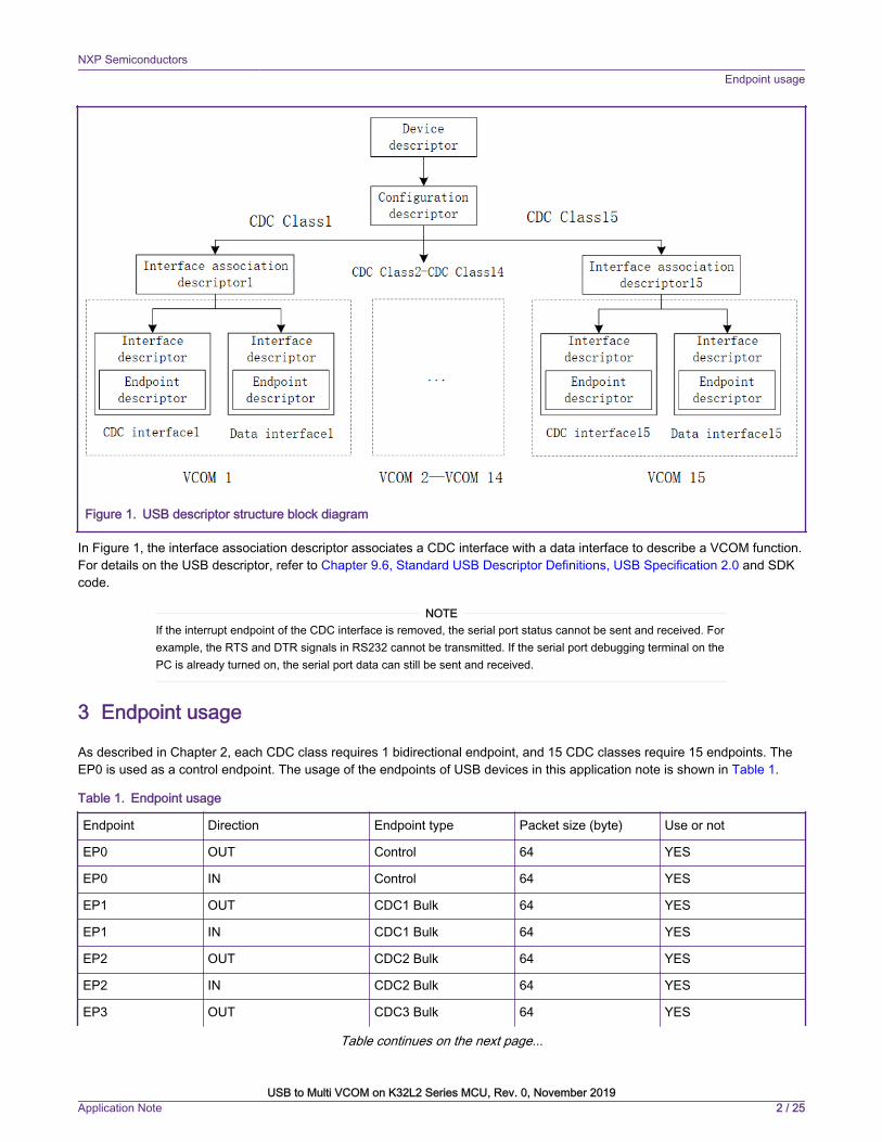
Figure 1. USB descriptor structure block diagram
In Figure 1, the interface association descriptor associates a CDC interface with a data interface to describe a VCOM function.For details on the USB descriptor, refer to Chapter 9.6, Standard USB Descriptor Definitions, USB Specification 2.0 and SDKcode.
If the interrupt endpoint of the CDC interface is removed, the serial port status cannot be sent and received. Forexample, the RTS and DTR signals in RS232 cannot be transmitted. If the serial port debugging terminal on thePC is already turned on, the serial port data can still be sent and received.
NOTE
3 Endpoint usage
As described in Chapter 2, each CDC class requires 1 bidirectional endpoint, and 15 CDC classes require 15 endpoints. TheEP0 is used as a control endpoint. The usage of the endpoints of USB devices in this application note is shown in Table 1.
Table 1. Endpoint usage
Endpoint Direction Endpoint type Packet size (byte) Use or not
EP0 OUT Control 64 YES
EP0 IN Control 64 YES
EP1 OUT CDC1 Bulk 64 YES
EP1 IN CDC1 Bulk 64 YES
EP2 OUT CDC2 Bulk 64 YES
EP2 IN CDC2 Bulk 64 YES
EP3 OUT CDC3 Bulk 64 YES
Table continues on the next page...
NXP SemiconductorsEndpoint usage
USB to Multi VCOM on K32L2 Series MCU, Rev. 0, November 2019Application Note 2 / 25
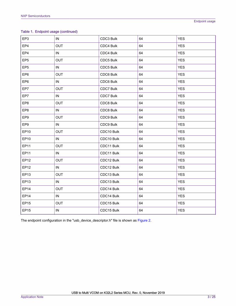
Table 1. Endpoint usage (continued)
EP3 IN CDC3 Bulk 64 YES
EP4 OUT CDC4 Bulk 64 YES
EP4 IN CDC4 Bulk 64 YES
EP5 OUT CDC5 Bulk 64 YES
EP5 IN CDC5 Bulk 64 YES
EP6 OUT CDC6 Bulk 64 YES
EP6 IN CDC6 Bulk 64 YES
EP7 OUT CDC7 Bulk 64 YES
EP7 IN CDC7 Bulk 64 YES
EP8 OUT CDC8 Bulk 64 YES
EP8 IN CDC8 Bulk 64 YES
EP9 OUT CDC9 Bulk 64 YES
EP9 IN CDC9 Bulk 64 YES
EP10 OUT CDC10 Bulk 64 YES
EP10 IN CDC10 Bulk 64 YES
EP11 OUT CDC11 Bulk 64 YES
EP11 IN CDC11 Bulk 64 YES
EP12 OUT CDC12 Bulk 64 YES
EP12 IN CDC12 Bulk 64 YES
EP13 OUT CDC13 Bulk 64 YES
EP13 IN CDC13 Bulk 64 YES
EP14 OUT CDC14 Bulk 64 YES
EP14 IN CDC14 Bulk 64 YES
EP15 OUT CDC15 Bulk 64 YES
EP15 IN CDC15 Bulk 64 YES
The endpoint configuration in the "usb_device_descriptor.h" file is shown as Figure 2.
NXP SemiconductorsEndpoint usage
USB to Multi VCOM on K32L2 Series MCU, Rev. 0, November 2019Application Note 3 / 25
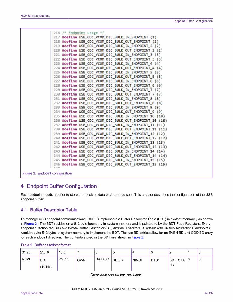
Figure 2. Endpoint configuration
4 Endpoint Buffer ConfigurationEach endpoint needs a buffer to store the received data or data to be sent. This chapter describes the configuration of the USBendpoint buffer.
4.1 Buffer Descriptor Table
To manage USB endpoint communications, USBFS implements a Buffer Descriptor Table (BDT) in system memory,as shownin Figure 3 . The BDT resides on a 512 byte boundary in system memory and is pointed to by the BDT Page Registers. Everyendpoint direction requires two 8-byte Buffer Descriptor (BD) entries. Therefore, a system with 16 fully bidirectional endpointswould require 512 bytes of system memory to implement the BDT. The two BD entries allow for an EVEN BD and ODD BD entryfor each endpoint direction. The contents stored in the BDT are shown in Table 2.
Table 2. Buffer descriptor format
31:26 25:16 15.8 7 6 5 4 3 2 1 0
RSVD BC
(10 bits)
RSVD OWN DATA0/1 KEEP/ NINC/ DTS/ BDT_STALL/
0 0
Table continues on the next page...
NXP SemiconductorsEndpoint Buffer Configuration
USB to Multi VCOM on K32L2 Series MCU, Rev. 0, November 2019Application Note 4 / 25
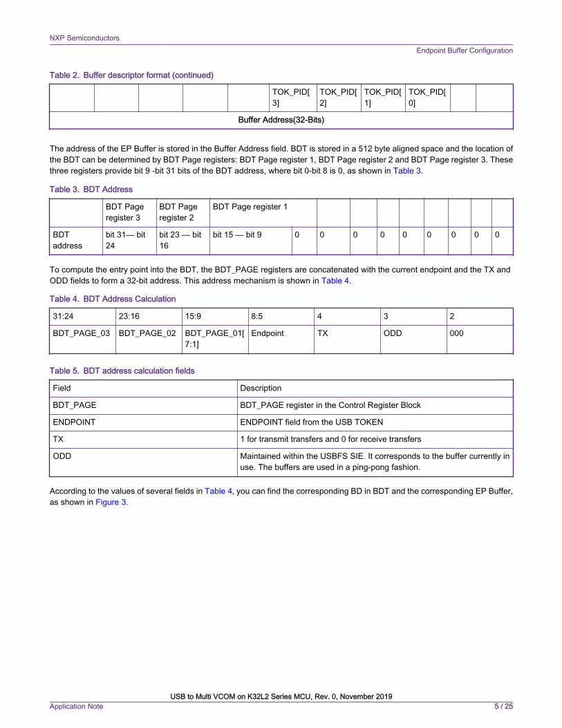
Table 2. Buffer descriptor format (continued)
TOK_PID[3]
TOK_PID[2]
TOK_PID[1]
TOK_PID[0]
Buffer Address(32-Bits)
The address of the EP Buffer is stored in the Buffer Address field. BDT is stored in a 512 byte aligned space and the location ofthe BDT can be determined by BDT Page registers: BDT Page register 1, BDT Page register 2 and BDT Page register 3. Thesethree registers provide bit 9 -bit 31 bits of the BDT address, where bit 0-bit 8 is 0, as shown in Table 3.
Table 3. BDT Address
BDT Pageregister 3
BDT Pageregister 2
BDT Page register 1
BDTaddress
bit 31— bit24
bit 23 — bit16
bit 15 — bit 9 0 0 0 0 0 0 0 0 0
To compute the entry point into the BDT, the BDT_PAGE registers are concatenated with the current endpoint and the TX andODD fields to form a 32-bit address. This address mechanism is shown in Table 4.
Table 4. BDT Address Calculation
31:24 23:16 15:9 8:5 4 3 2
BDT_PAGE_03 BDT_PAGE_02 BDT_PAGE_01[7:1]
Endpoint TX ODD 000
Table 5. BDT address calculation fields
Field Description
BDT_PAGE BDT_PAGE register in the Control Register Block
ENDPOINT ENDPOINT field from the USB TOKEN
TX 1 for transmit transfers and 0 for receive transfers
ODD Maintained within the USBFS SIE. It corresponds to the buffer currently inuse. The buffers are used in a ping-pong fashion.
According to the values of several fields in Table 4, you can find the corresponding BD in BDT and the corresponding EP Buffer,as shown in Figure 3.
NXP SemiconductorsEndpoint Buffer Configuration
USB to Multi VCOM on K32L2 Series MCU, Rev. 0, November 2019Application Note 5 / 25
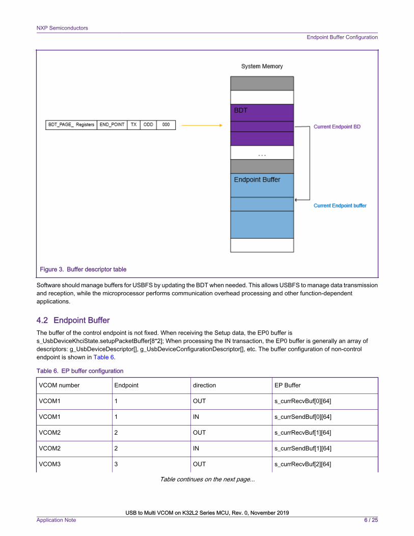
Figure 3. Buffer descriptor table
Software should manage buffers for USBFS by updating the BDT when needed. This allows USBFS to manage data transmissionand reception, while the microprocessor performs communication overhead processing and other function-dependentapplications.
4.2 Endpoint BufferThe buffer of the control endpoint is not fixed. When receiving the Setup data, the EP0 buffer iss_UsbDeviceKhciState.setupPacketBuffer[8*2]; When processing the IN transaction, the EP0 buffer is generally an array ofdescriptors: g_UsbDeviceDescriptor[], g_UsbDeviceConfigurationDescriptor[], etc. The buffer configuration of non-controlendpoint is shown in Table 6.
Table 6. EP buffer configuration
VCOM number Endpoint direction EP Buffer
VCOM1 1 OUT s_currRecvBuf[0][64]
VCOM1 1 IN s_currSendBuf[0][64]
VCOM2 2 OUT s_currRecvBuf[1][64]
VCOM2 2 IN s_currSendBuf[1][64]
VCOM3 3 OUT s_currRecvBuf[2][64]
Table continues on the next page...
NXP SemiconductorsEndpoint Buffer Configuration
USB to Multi VCOM on K32L2 Series MCU, Rev. 0, November 2019Application Note 6 / 25
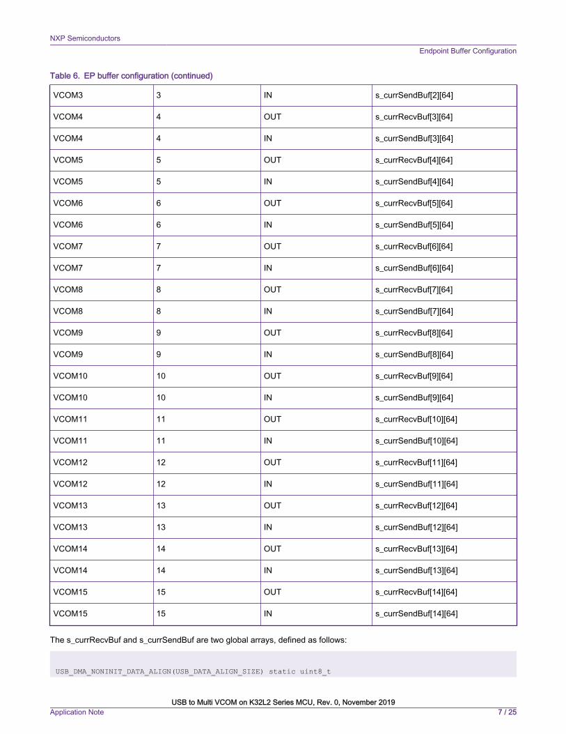
Table 6. EP buffer configuration (continued)
VCOM3 3 IN s_currSendBuf[2][64]
VCOM4 4 OUT s_currRecvBuf[3][64]
VCOM4 4 IN s_currSendBuf[3][64]
VCOM5 5 OUT s_currRecvBuf[4][64]
VCOM5 5 IN s_currSendBuf[4][64]
VCOM6 6 OUT s_currRecvBuf[5][64]
VCOM6 6 IN s_currSendBuf[5][64]
VCOM7 7 OUT s_currRecvBuf[6][64]
VCOM7 7 IN s_currSendBuf[6][64]
VCOM8 8 OUT s_currRecvBuf[7][64]
VCOM8 8 IN s_currSendBuf[7][64]
VCOM9 9 OUT s_currRecvBuf[8][64]
VCOM9 9 IN s_currSendBuf[8][64]
VCOM10 10 OUT s_currRecvBuf[9][64]
VCOM10 10 IN s_currSendBuf[9][64]
VCOM11 11 OUT s_currRecvBuf[10][64]
VCOM11 11 IN s_currSendBuf[10][64]
VCOM12 12 OUT s_currRecvBuf[11][64]
VCOM12 12 IN s_currSendBuf[11][64]
VCOM13 13 OUT s_currRecvBuf[12][64]
VCOM13 13 IN s_currSendBuf[12][64]
VCOM14 14 OUT s_currRecvBuf[13][64]
VCOM14 14 IN s_currSendBuf[13][64]
VCOM15 15 OUT s_currRecvBuf[14][64]
VCOM15 15 IN s_currSendBuf[14][64]
The s_currRecvBuf and s_currSendBuf are two global arrays, defined as follows:
USB_DMA_NONINIT_DATA_ALIGN(USB_DATA_ALIGN_SIZE) static uint8_t
NXP SemiconductorsEndpoint Buffer Configuration
USB to Multi VCOM on K32L2 Series MCU, Rev. 0, November 2019Application Note 7 / 25
s_currRecvBuf[USB_DEVICE_CONFIG_CDC_ACM][DATA_BUFF_SIZE];USB_DMA_NONINIT_DATA_ALIGN(USB_DATA_ALIGN_SIZE) static uint8_t s_currSendBuf[USB_DEVICE_CONFIG_CDC_ACM][DATA_BUFF_SIZE];
The value of the macro DATA_BUFF_SIZE is 64.
The buffer configuration of non-control endpoint of the OUT direction is performed in the USB_DeviceCdcVcomSetConfigure()function after the USB device receives the SetConfiguration standard request from the host, while the EP Buffer of the IN directionis configured before the data will be sent using this IN endpoint.
5 Software workflow chart
The code used in this application note is based on the
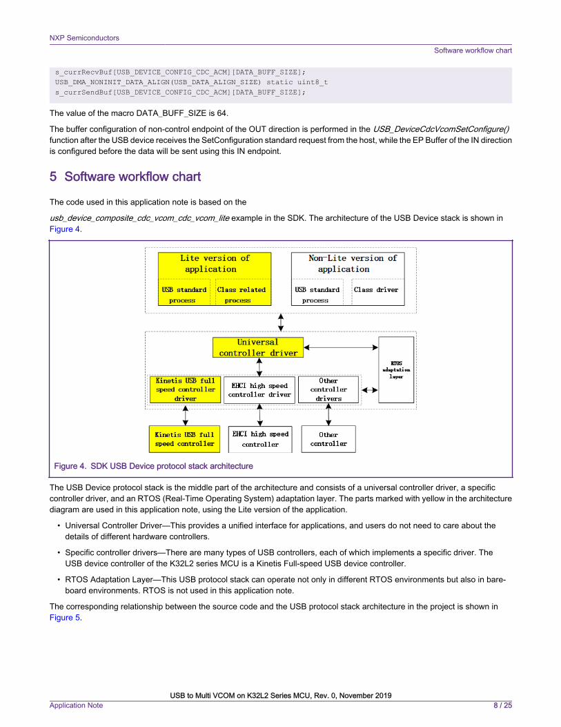
usb_device_composite_cdc_vcom_cdc_vcom_lite example in the SDK. The architecture of the USB Device stack is shown in Figure 4.
Figure 4. SDK USB Device protocol stack architecture
The USB Device protocol stack is the middle part of the architecture and consists of a universal controller driver, a specificcontroller driver, and an RTOS (Real-Time Operating System) adaptation layer. The parts marked with yellow in the architecturediagram are used in this application note, using the Lite version of the application.
• Universal Controller Driver—This provides a unified interface for applications, and users do not need to care about thedetails of different hardware controllers.
• Specific controller drivers—There are many types of USB controllers, each of which implements a specific driver. TheUSB device controller of the K32L2 series MCU is a Kinetis Full-speed USB device controller.
• RTOS Adaptation Layer—This USB protocol stack can operate not only in different RTOS environments but also in bare-board environments. RTOS is not used in this application note.
The corresponding relationship between the source code and the USB protocol stack architecture in the project is shown in Figure 5.
NXP SemiconductorsSoftware workflow chart
USB to Multi VCOM on K32L2 Series MCU, Rev. 0, November 2019Application Note 8 / 25
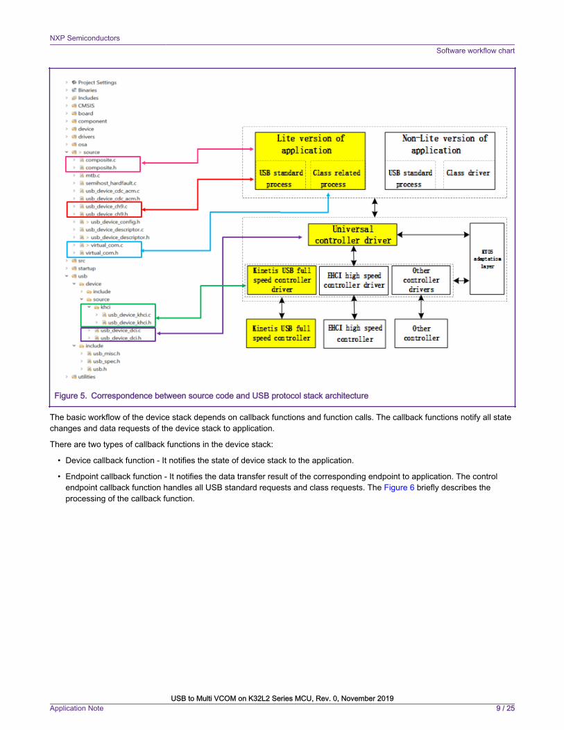
Figure 5. Correspondence between source code and USB protocol stack architecture
The basic workflow of the device stack depends on callback functions and function calls. The callback functions notify all statechanges and data requests of the device stack to application.
There are two types of callback functions in the device stack:
• Device callback function - It notifies the state of device stack to the application.
• Endpoint callback function - It notifies the data transfer result of the corresponding endpoint to application. The controlendpoint callback function handles all USB standard requests and class requests. The Figure 6 briefly describes theprocessing of the callback function.
NXP SemiconductorsSoftware workflow chart
USB to Multi VCOM on K32L2 Series MCU, Rev. 0, November 2019Application Note 9 / 25

Figure 6. Callback function processing
When the USB host recognizes that a USB device is plugged into the USB interface, it starts an enumeration process. Theessence of USB enumeration is the process in which the USB host obtains the parameter information of the USB device andconfigures the configurable parameters. The USB enumeration process is done in the USB interrupt service function. Theprocessing flow of the USB interrupt service function is shown in Figure 7.
NXP SemiconductorsSoftware workflow chart
USB to Multi VCOM on K32L2 Series MCU, Rev. 0, November 2019Application Note 10 / 25
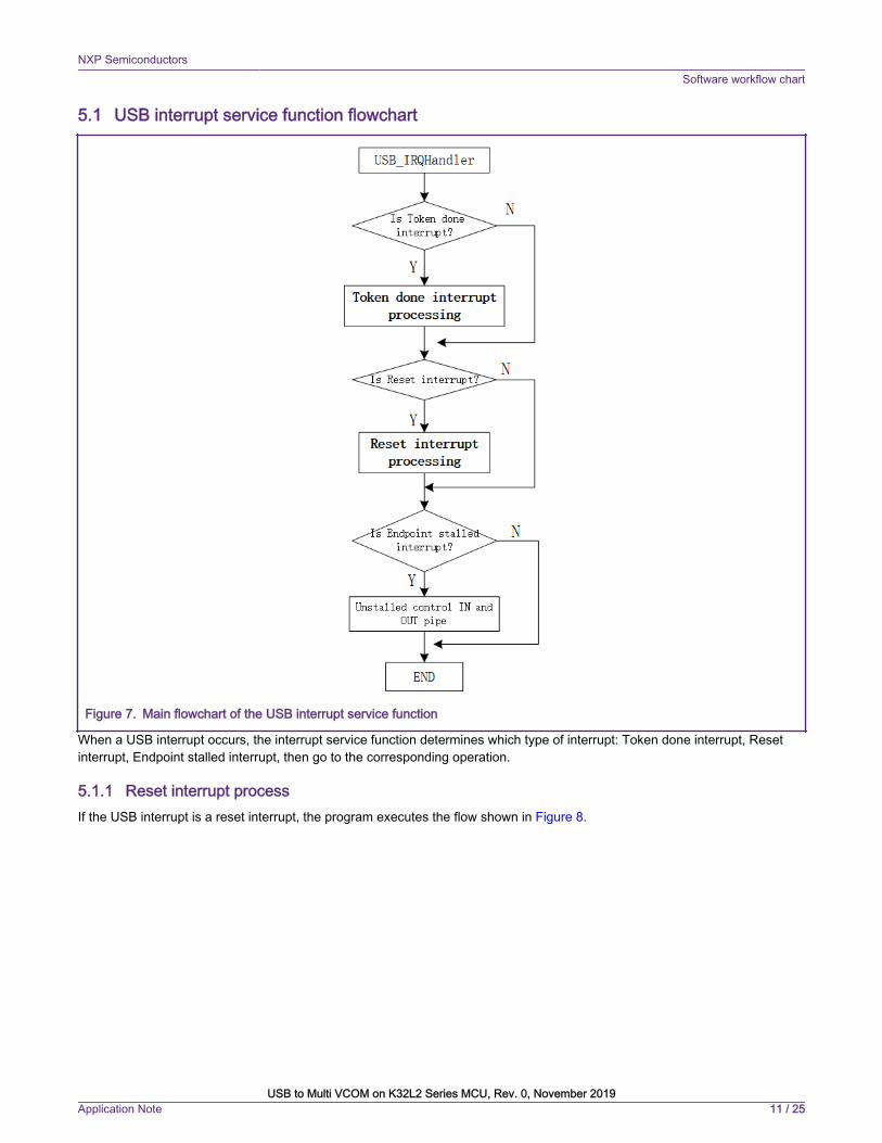
5.1 USB interrupt service function flowchart
Figure 7. Main flowchart of the USB interrupt service function
When a USB interrupt occurs, the interrupt service function determines which type of interrupt: Token done interrupt, Resetinterrupt, Endpoint stalled interrupt, then go to the corresponding operation.
5.1.1 Reset interrupt processIf the USB interrupt is a reset interrupt, the program executes the flow shown in Figure 8.
NXP SemiconductorsSoftware workflow chart
USB to Multi VCOM on K32L2 Series MCU, Rev. 0, November 2019Application Note 11 / 25
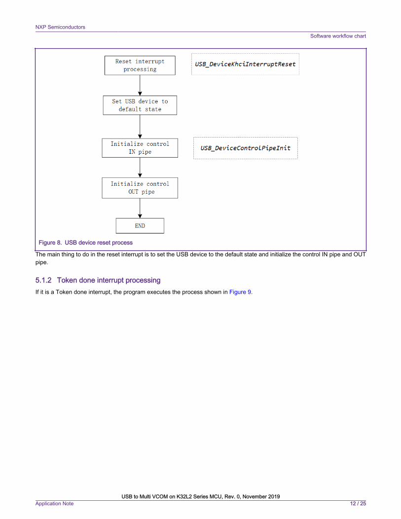
Figure 8. USB device reset process
The main thing to do in the reset interrupt is to set the USB device to the default state and initialize the control IN pipe and OUTpipe.
5.1.2 Token done interrupt processingIf it is a Token done interrupt, the program executes the process shown in Figure 9.
NXP SemiconductorsSoftware workflow chart
USB to Multi VCOM on K32L2 Series MCU, Rev. 0, November 2019Application Note 12 / 25

Figure 9. Token done interrupt processing
The endpoint callback function includes two types: control endpoint callback function and non-control endpoint callback function.If the current endpoint is a control endpoint, the control endpoint callback function is called; if the current endpoint is a non-controlendpoint, the non-control endpoint callback function is called. The callback function of the control endpoint implements theprocessing of standard and class requests; the non-control endpoint callback function implements the data transmission function,and transmits the data received by the Bluk OUT endpoint to the host through the Bluk IN endpoint. The non-control endpointcallback functions for the 15 VCOMs in this application note are the same. The endpoint callback function in IN direction isUSB_DeviceCdcAcmBulkIn(), and the callback function in OUT direction is USB_DeviceCdcAcmBulkOut(), that is, the functionsof the 15 VCOMs implementations are the same: transmits the data received from USB host to the USB host.
5.2 USB device requestThe processing of standard requests and class requests is performed in the callback function of the control endpoint. The USBhost obtains the information of the USB device and performs related configuration on the USB device by sending a device request
NXP SemiconductorsSoftware workflow chart
USB to Multi VCOM on K32L2 Series MCU, Rev. 0, November 2019Application Note 13 / 25
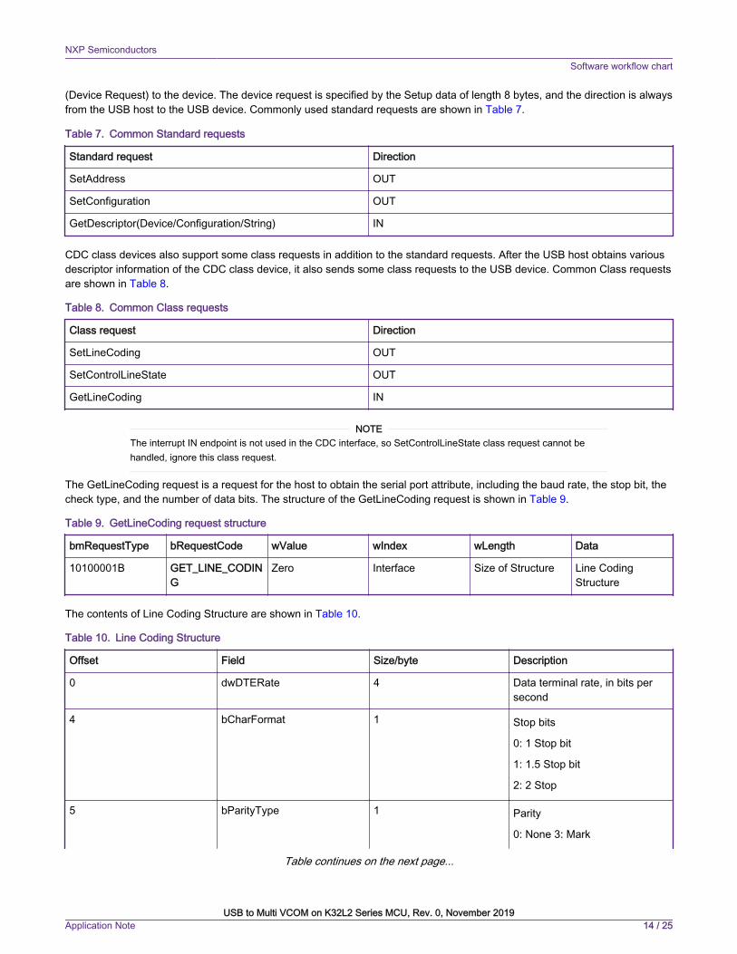
(Device Request) to the device. The device request is specified by the Setup data of length 8 bytes, and the direction is alwaysfrom the USB host to the USB device. Commonly used standard requests are shown in Table 7.
Table 7. Common Standard requests
Standard request Direction
SetAddress OUT
SetConfiguration OUT
GetDescriptor(Device/Configuration/String) IN
CDC class devices also support some class requests in addition to the standard requests. After the USB host obtains variousdescriptor information of the CDC class device, it also sends some class requests to the USB device. Common Class requestsare shown in Table 8.
Table 8. Common Class requests
Class request Direction
SetLineCoding OUT
SetControlLineState OUT
GetLineCoding IN
The interrupt IN endpoint is not used in the CDC interface, so SetControlLineState class request cannot behandled, ignore this class request.
NOTE
The GetLineCoding request is a request for the host to obtain the serial port attribute, including the baud rate, the stop bit, thecheck type, and the number of data bits. The structure of the GetLineCoding request is shown in Table 9.
Table 9. GetLineCoding request structure
bmRequestType bRequestCode wValue wIndex wLength Data
10100001B GET_LINE_CODING
Zero Interface Size of Structure Line CodingStructure
The contents of Line Coding Structure are shown in Table 10.
Table 10. Line Coding Structure
Offset Field Size/byte Description
0 dwDTERate 4 Data terminal rate, in bits persecond
4 bCharFormat 1 Stop bits
0: 1 Stop bit
1: 1.5 Stop bit
2: 2 Stop
5 bParityType 1 Parity
0: None 3: Mark
Table continues on the next page...
NXP SemiconductorsSoftware workflow chart
USB to Multi VCOM on K32L2 Series MCU, Rev. 0, November 2019Application Note 14 / 25

Table 10. Line Coding Structure (continued)
1: Odd 4: Space
2: Even
6 bDataBits 1 Data bits (5,6,7,8 or 16)
SetLineCoding is an output class request, which corresponds to GetLineCoding. The USB host uses this command to set theserial port property of the device, and its data structure is the same as GetLineCoding. After the USB host completes thesestandard requests and class requests, the enumeration process ends, and the USB host will recognize multiple VCOMs. Thenthe serial port debugging terminal on the PC can communicate with the USB device of the K32L2 series MCU.
6 Key Steps
6.1 How to expand the number of supported VCOMsThis section uses the SDK code dev_composite_cdc_vcom_cdc_vcom_lite_bm as an example to show how to extend to threeVCOMs based on two VCOMs. The specific steps are as follows:
1. Modify the usb_device_config.h file
• Change the value of the macro USB_DEVICE_CONFIG_CDC_ACM from 2 to 3
#define USB_DEVICE_CONFIG_CDC_ACM (2U) to#define USB_DEVICE_CONFIG_CDC_ACM (3U)
• Modify the value of the USB_DEVICE_CONFIG_ENDPOINTS macro
#define USB_DEVICE_CONFIG_ENDPOINTS (5U) to/* Values that meet functional requirements are ok */#define USB_DEVICE_CONFIG_ENDPOINTS (8U)
2. Modify the usb_device_descriptor.h file
• Change the value of the macro USB_INTERFACE_COUNT from 4 to 6
#define USB_INTERFACE_COUNT (4) to#define USB_INTERFACE_COUNT (6)
• Add some macro definitions for VCOM3
#define USB_CDC_VCOM_INTERFACE_COUNT_3 (2)
#define USB_CDC_VCOM_CIC_INTERFACE_INDEX_3 (4)#define USB_CDC_VCOM_DIC_INTERFACE_INDEX_3 (5)/* If the CDC interface does not require an Interrupt IN endpoint, then this macro is 0 */#define USB_CDC_VCOM_CIC_ENDPOINT_COUNT_3 (1)
/* If the CDC interface does not require an Interrupt IN endpoint, you do not need to define this macro*/#define USB_CDC_VCOM_CIC_INTERRUPT_IN_ENDPOINT_3 (7)
#define USB_CDC_VCOM_DIC_ENDPOINT_COUNT_3 (2)#define USB_CDC_VCOM_DIC_BULK_IN_ENDPOINT_3 (3)#define USB_CDC_VCOM_DIC_BULK_OUT_ENDPOINT_3 (3)
#define HS_CDC_VCOM_INTERRUPT_IN_PACKET_SIZE_3 (16)#define FS_CDC_VCOM_INTERRUPT_IN_PACKET_SIZE_3 (16)
NXP SemiconductorsKey Steps
USB to Multi VCOM on K32L2 Series MCU, Rev. 0, November 2019Application Note 15 / 25
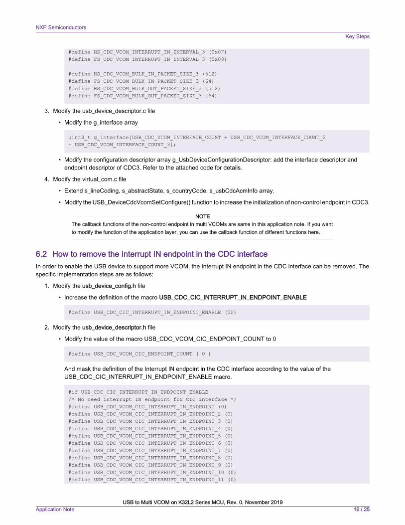
#define HS_CDC_VCOM_INTERRUPT_IN_INTERVAL_3 (0x07)#define FS_CDC_VCOM_INTERRUPT_IN_INTERVAL_3 (0x08)
#define HS_CDC_VCOM_BULK_IN_PACKET_SIZE_3 (512)#define FS_CDC_VCOM_BULK_IN_PACKET_SIZE_3 (64)#define HS_CDC_VCOM_BULK_OUT_PACKET_SIZE_3 (512)#define FS_CDC_VCOM_BULK_OUT_PACKET_SIZE_3 (64)
3. Modify the usb_device_descriptor.c file
• Modify the g_interface array
uint8_t g_interface[USB_CDC_VCOM_INTERFACE_COUNT + USB_CDC_VCOM_INTERFACE_COUNT_2 + USB_CDC_VCOM_INTERFACE_COUNT_3];
• Modify the configuration descriptor array g_UsbDeviceConfigurationDescriptor: add the interface descriptor andendpoint descriptor of CDC3. Refer to the attached code for details.
4. Modify the virtual_com.c file
• Extend s_lineCoding, s_abstractState, s_countryCode, s_usbCdcAcmInfo array.
• Modify the USB_DeviceCdcVcomSetConfigure() function to increase the initialization of non-control endpoint in CDC3.
The callback functions of the non-control endpoint in multi VCOMs are same in this application note. If you wantto modify the function of the application layer, you can use the callback function of different functions here.
NOTE
6.2 How to remove the Interrupt IN endpoint in the CDC interfaceIn order to enable the USB device to support more VCOM, the Interrupt IN endpoint in the CDC interface can be removed. Thespecific implementation steps are as follows:
1. Modify the usb_device_config.h file
• Increase the definition of the macro USB_CDC_CIC_INTERRUPT_IN_ENDPOINT_ENABLE
#define USB_CDC_CIC_INTERRUPT_IN_ENDPOINT_ENABLE (0U)
2. Modify the usb_device_descriptor.h file
• Modify the value of the macro USB_CDC_VCOM_CIC_ENDPOINT_COUNT to 0
#define USB_CDC_VCOM_CIC_ENDPOINT_COUNT ( 0 )
And mask the definition of the Interrupt IN endpoint in the CDC interface according to the value of theUSB_CDC_CIC_INTERRUPT_IN_ENDPOINT_ENABLE macro.
#if USB_CDC_CIC_INTERRUPT_IN_ENDPOINT_ENABLE/* No need interrupt IN endpoint for CIC interface */#define USB_CDC_VCOM_CIC_INTERRUPT_IN_ENDPOINT (0)#define USB_CDC_VCOM_CIC_INTERRUPT_IN_ENDPOINT_2 (0)#define USB_CDC_VCOM_CIC_INTERRUPT_IN_ENDPOINT_3 (0)#define USB_CDC_VCOM_CIC_INTERRUPT_IN_ENDPOINT_4 (0)#define USB_CDC_VCOM_CIC_INTERRUPT_IN_ENDPOINT_5 (0)#define USB_CDC_VCOM_CIC_INTERRUPT_IN_ENDPOINT_6 (0)#define USB_CDC_VCOM_CIC_INTERRUPT_IN_ENDPOINT_7 (0)#define USB_CDC_VCOM_CIC_INTERRUPT_IN_ENDPOINT_8 (0)#define USB_CDC_VCOM_CIC_INTERRUPT_IN_ENDPOINT_9 (0)#define USB_CDC_VCOM_CIC_INTERRUPT_IN_ENDPOINT_10 (0)#define USB_CDC_VCOM_CIC_INTERRUPT_IN_ENDPOINT_11 (0)
NXP SemiconductorsKey Steps
USB to Multi VCOM on K32L2 Series MCU, Rev. 0, November 2019Application Note 16 / 25

#define USB_CDC_VCOM_CIC_INTERRUPT_IN_ENDPOINT_12 (0)#define USB_CDC_VCOM_CIC_INTERRUPT_IN_ENDPOINT_13 (0)#define USB_CDC_VCOM_CIC_INTERRUPT_IN_ENDPOINT_14 (0)#define USB_CDC_VCOM_CIC_INTERRUPT_IN_ENDPOINT_15 (0)#endif
3. Modify the usb_device_descriptor.c file
• Modify the array length field in the g_UsbDeviceConfigurationDescriptor configuration descriptor array
USB_SHORT_GET_LOW(USB_DESCRIPTOR_LENGTH_CONFIGURE + (USB_IAD_DESC_SIZE + USB_DESCRIPTOR_LENGTH_INTERFACE + USB_DESCRIPTOR_LENGTH_CDC_HEADER_FUNC + USB_DESCRIPTOR_LENGTH_CDC_CALL_MANAG + USB_DESCRIPTOR_LENGTH_CDC_ABSTRACT + USB_DESCRIPTOR_LENGTH_CDC_UNION_FUNC + 0 + USB_DESCRIPTOR_LENGTH_INTERFACE + USB_DESCRIPTOR_LENGTH_ENDPOINT + USB_DESCRIPTOR_LENGTH_ENDPOINT) * USB_DEVICE_CONFIG_CDC_ACM),USB_SHORT_GET_HIGH(USB_DESCRIPTOR_LENGTH_CONFIGURE + (USB_IAD_DESC_SIZE + USB_DESCRIPTOR_LENGTH_INTERFACE + USB_DESCRIPTOR_LENGTH_CDC_HEADER_FUNC + USB_DESCRIPTOR_LENGTH_CDC_CALL_MANAG + USB_DESCRIPTOR_LENGTH_CDC_ABSTRACT + USB_DESCRIPTOR_LENGTH_CDC_UNION_FUNC + 0 + USB_DESCRIPTOR_LENGTH_INTERFACE + USB_DESCRIPTOR_LENGTH_ENDPOINT + USB_DESCRIPTOR_LENGTH_ENDPOINT) * USB_DEVICE_CONFIG_CDC_ACM),
• Delete interrupt endpoint descriptors in all CDC interfaces
#if USB_CDC_CIC_INTERRUPT_IN_ENDPOINT_ENABLE /*Notification Endpoint descriptor */ USB_DESCRIPTOR_LENGTH_ENDPOINT, USB_DESCRIPTOR_TYPE_ENDPOINT, USB_CDC_VCOM_CIC_INTERRUPT_IN_ENDPOINT |(USB_IN << 7U), USB_ENDPOINT_INTERRUPT, USB_SHORT_GET_LOW(FS_CDC_VCOM_INTERRUPT_IN_PACKET_SIZE), USB_SHORT_GET_HIGH(FS_CDC_VCOM_INTERRUPT_IN_PACKET_SIZE), FS_CDC_VCOM_INTERRUPT_IN_INTERVAL, #endif
4. Modify the virtual_com.c file
• Modify the processing of the SetControlLineState class request in the USB_DeviceCdcVcomClassRequest() function.
if (0 == vcomInstance->hasSentState) {#if USB_CDC_CIC_INTERRUPT_IN_ENDPOINT_ENABLE error = USB_DeviceSendRequest(handle, vcomInstance->interruptEndpoint, acmInfo->serialStateBuf, len); if (kStatus_USB_Success != error) { usb_echo("kUSB_DeviceCdcEventSetControlLineState error!"); }#endif vcomInstance->hasSentState = 1;}
• Add g_CdcVcomInterruptInPackageSzie, g_CdcVcomInterruptInInterval, g_CdcVcomInterruptInEndpoint, g_CdcVcomDicBulkInEndpoint, g_CdcVcomDicBulkInEndpoint, g_CdcVcomDicBulkOutEndpoint,
NXP SemiconductorsKey Steps
USB to Multi VCOM on K32L2 Series MCU, Rev. 0, November 2019Application Note 17 / 25
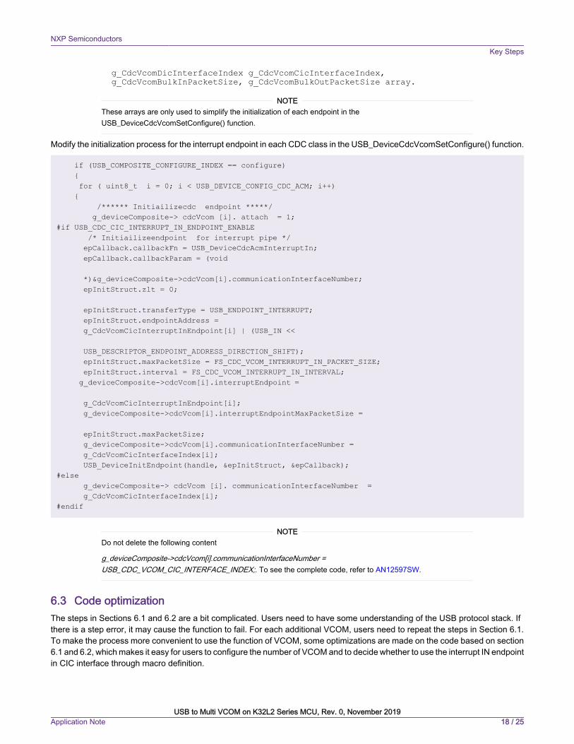
g_CdcVcomDicInterfaceIndex g_CdcVcomCicInterfaceIndex, g_CdcVcomBulkInPacketSize, g_CdcVcomBulkOutPacketSize array.
These arrays are only used to simplify the initialization of each endpoint in theUSB_DeviceCdcVcomSetConfigure() function.
NOTE
Modify the initialization process for the interrupt endpoint in each CDC class in the USB_DeviceCdcVcomSetConfigure() function.
if (USB_COMPOSITE_CONFIGURE_INDEX == configure) { for ( uint8_t i = 0; i < USB_DEVICE_CONFIG_CDC_ACM; i++) { /****** Initiailizecdc endpoint *****/ g_deviceComposite-> cdcVcom [i]. attach = 1;#if USB_CDC_CIC_INTERRUPT_IN_ENDPOINT_ENABLE /* Initiailizeendpoint for interrupt pipe */ epCallback.callbackFn = USB_DeviceCdcAcmInterruptIn; epCallback.callbackParam = (void *)&g_deviceComposite->cdcVcom[i].communicationInterfaceNumber; epInitStruct.zlt = 0; epInitStruct.transferType = USB_ENDPOINT_INTERRUPT; epInitStruct.endpointAddress = g_CdcVcomCicInterruptInEndpoint[i] | (USB_IN << USB_DESCRIPTOR_ENDPOINT_ADDRESS_DIRECTION_SHIFT); epInitStruct.maxPacketSize = FS_CDC_VCOM_INTERRUPT_IN_PACKET_SIZE; epInitStruct.interval = FS_CDC_VCOM_INTERRUPT_IN_INTERVAL; g_deviceComposite->cdcVcom[i].interruptEndpoint = g_CdcVcomCicInterruptInEndpoint[i]; g_deviceComposite->cdcVcom[i].interruptEndpointMaxPacketSize = epInitStruct.maxPacketSize; g_deviceComposite->cdcVcom[i].communicationInterfaceNumber = g_CdcVcomCicInterfaceIndex[i]; USB_DeviceInitEndpoint(handle, &epInitStruct, &epCallback);#else g_deviceComposite-> cdcVcom [i]. communicationInterfaceNumber = g_CdcVcomCicInterfaceIndex[i];#endif
Do not delete the following content
g_deviceComposite->cdcVcom[i].communicationInterfaceNumber =USB_CDC_VCOM_CIC_INTERFACE_INDEX;. To see the complete code, refer to AN12597SW.
NOTE
6.3 Code optimizationThe steps in Sections 6.1 and 6.2 are a bit complicated. Users need to have some understanding of the USB protocol stack. Ifthere is a step error, it may cause the function to fail. For each additional VCOM, users need to repeat the steps in Section 6.1.To make the process more convenient to use the function of VCOM, some optimizations are made on the code based on section6.1 and 6.2, which makes it easy for users to configure the number of VCOM and to decide whether to use the interrupt IN endpointin CIC interface through macro definition.
NXP SemiconductorsKey Steps
USB to Multi VCOM on K32L2 Series MCU, Rev. 0, November 2019Application Note 18 / 25

6.3.1 Use loop instead of listFor example, the USB_DeviceCdcVcomConfigureEndpointStatus () function in the virtual_com.c file:
usb_status_t USB_DeviceCdcVcomConfigureEndpointStatus(usb_device_handle handle, uint8_t ep, uint8_t status){ usb_status_t error = kStatus_USB_Error; if (status) { if ((USB_CDC_VCOM_DIC_BULK_IN_ENDPOINT == (ep & USB_ENDPOINT_NUMBER_MASK)) && (ep & USB_DESCRIPTOR_ENDPOINT_ADDRESS_DIRECTION_MASK)) { error = USB_DeviceStallEndpoint(handle, ep); } else if ((USB_CDC_VCOM_DIC_BULK_OUT_ENDPOINT == (ep & USB_ENDPOINT_NUMBER_MASK)) && (!(ep & USB_DESCRIPTOR_ENDPOINT_ADDRESS_DIRECTION_MASK))) { error = USB_DeviceStallEndpoint(handle, ep); } else if ((USB_CDC_VCOM_DIC_BULK_IN_ENDPOINT_2 == (ep & USB_ENDPOINT_NUMBER_MASK)) && (ep & USB_DESCRIPTOR_ENDPOINT_ADDRESS_DIRECTION_MASK)) { error = USB_DeviceStallEndpoint(handle, ep); } else if ((USB_CDC_VCOM_DIC_BULK_OUT_ENDPOINT_2 == (ep & USB_ENDPOINT_NUMBER_MASK)) && ( !(ep & USB_DESCRIPTOR_ENDPOINT_ADDRESS_DIRECTION_MASK))) { error = USB_DeviceStallEndpoint(handle, ep); } else { } } else { if ((USB_CDC_VCOM_DIC_BULK_IN_ENDPOINT == (ep & USB_ENDPOINT_NUMBER_MASK)) && (ep & USB_DESCRIPTOR_ENDPOINT_ADDRESS_DIRECTION_MASK)) { error = USB_DeviceUnstallEndpoint(handle, ep); } else if ((USB_CDC_VCOM_DIC_BULK_OUT_ENDPOINT == (ep & USB_ENDPOINT_NUMBER_MASK)) && (!(ep & USB_DESCRIPTOR_ENDPOINT_ADDRESS_DIRECTION_MASK))) { error = USB_DeviceUnstallEndpoint(handle, ep); } else if ((USB_CDC_VCOM_DIC_BULK_IN_ENDPOINT_2 == (ep & USB_ENDPOINT_NUMBER_MASK)) && (ep & USB_DESCRIPTOR_ENDPOINT_ADDRESS_DIRECTION_MASK)) { error = USB_DeviceUnstallEndpoint(handle, ep); } else if ((USB_CDC_VCOM_DIC_BULK_OUT_ENDPOINT_2 == (ep & USB_ENDPOINT_NUMBER_MASK)) && (!(ep & USB_DESCRIPTOR_ENDPOINT_ADDRESS_DIRECTION_MASK))) { error = USB_DeviceUnstallEndpoint(handle, ep); } else { }
NXP SemiconductorsKey Steps
USB to Multi VCOM on K32L2 Series MCU, Rev. 0, November 2019Application Note 19 / 25

} return error; }
usb_status_t USB_DeviceCdcVcomConfigureEndpointStatus(usb_device_handle handle, uint8_t ep, uint8_t status){ usb_status_t error = kStatus_USB_Error; uint8_t i; if (status) { for(i = 0; i < USB_DEVICE_CONFIG_CDC_ACM; i++) { if ((g_CdcVcomDicBulkInEndpoint[i] == (ep & USB_ENDPOINT_NUMBER_MASK)) && (ep & USB_DESCRIPTOR_ENDPOINT_ADDRESS_DIRECTION_MASK)) { error = USB_DeviceStallEndpoint(handle, ep); } else if ((g_CdcVcomDicBulkOutEndpoint[i] == (ep & USB_ENDPOINT_NUMBER_MASK)) && ep & USB_DESCRIPTOR_ENDPOINT_ADDRESS_DIRECTION_MASK)) { error = USB_DeviceStallEndpoint(handle, ep); } } } else { for(i = 0; i < USB_DEVICE_CONFIG_CDC_ACM; i++) { if ((g_CdcVcomDicBulkInEndpoint[i] == (ep & USB_ENDPOINT_NUMBER_MASK)) && (ep & USB_DESCRIPTOR_ENDPOINT_ADDRESS_DIRECTION_MASK)) { error = USB_DeviceUnstallEndpoint(handle, ep); } else if ((g_CdcVcomDicBulkOutEndpoint[i] == (ep & USB_ENDPOINT_NUMBER_MASK)) && (ep & USB_DESCRIPTOR_ENDPOINT_ADDRESS_DIRECTION_MASK)) { error = USB_DeviceUnstallEndpoint(handle, ep); } }}return error;}
There is a lot code in fact can be replaced by loop, It is a key step to make automatic composite class for application. Other similarcode is not listed here, Refer to the code released with this application note for more details.
6.3.2 Remove unnecessary settingsThe following settings can be merged, as in most cases, user do not need to tune the parameters at all. Even in some specialcase that some users need to tune the parameters, it is also supported in runtime initialization.
/* Packet size. */#define HS_CDC_VCOM_INTERRUPT_IN_PACKET_SIZE (16)#define FS_CDC_VCOM_INTERRUPT_IN_PACKET_SIZE (16)#define HS_CDC_VCOM_INTERRUPT_IN_INTERVAL (0x07) /* 2^(7-1) = 8ms */#define FS_CDC_VCOM_INTERRUPT_IN_INTERVAL (0x08)
NXP SemiconductorsKey Steps
USB to Multi VCOM on K32L2 Series MCU, Rev. 0, November 2019Application Note 20 / 25

/* Packet size. */#define HS_CDC_VCOM_INTERRUPT_IN_PACKET_SIZE_2 (16)#define FS_CDC_VCOM_INTERRUPT_IN_PACKET_SIZE_2 (16)#define HS_CDC_VCOM_INTERRUPT_IN_INTERVAL_2 (0x07) /* 2^(7-1) = 8ms */#define FS_CDC_VCOM_INTERRUPT_IN_INTERVAL_2 (0x08)#define HS_CDC_VCOM_INTERRUPT_IN_PACKET_SIZE_3 (16)#define FS_CDC_VCOM_INTERRUPT_IN_PACKET_SIZE_3 (16)#define HS_CDC_VCOM_INTERRUPT_IN_INTERVAL_3 (0x07) /* 2^(7-1) = 8ms */#define FS_CDC_VCOM_INTERRUPT_IN_INTERVAL_3 (0x08)#define HS_CDC_VCOM_INTERRUPT_IN_PACKET_SIZE_4 (16)#define FS_CDC_VCOM_INTERRUPT_IN_PACKET_SIZE_4 (16)#define HS_CDC_VCOM_INTERRUPT_IN_INTERVAL_4 (0x07) /* 2^(7-1) = 8ms */#define FS_CDC_VCOM_INTERRUPT_IN_INTERVAL_4 (0x08)#define HS_CDC_VCOM_INTERRUPT_IN_PACKET_SIZE_5 (16)#define FS_CDC_VCOM_INTERRUPT_IN_PACKET_SIZE_5 (16)#define HS_CDC_VCOM_INTERRUPT_IN_INTERVAL_5 (0x07) /* 2^(7-1) = 8ms */#define FS_CDC_VCOM_INTERRUPT_IN_INTERVAL_5 (0x08)...
After merge, the above code becomes:
/* Packet size. */#define HS_CDC_VCOM_INTERRUPT_IN_PACKET_SIZE (16)#define FS_CDC_VCOM_INTERRUPT_IN_PACKET_SIZE (16)#define HS_CDC_VCOM_INTERRUPT_IN_INTERVAL (0x07) /* 2^(7-1) = 8ms */#define FS_CDC_VCOM_INTERRUPT_IN_INTERVAL (0x08)
Other similar code is not listed here, refer to the code attached with this application note for more details.
6.3.3 Use MACRO to avoid modify code manually
#define USB_INTERFACE_COUNT (30)
#define USB_INTERFACE_COUNT (2*USB_DEVICE_CONFIG_CDC_ACM)
#define USB_DEVICE_CONFIG_ENDPOINTS (16U)
#define USB_DEVICE_CONFIG_ENDPOINTS (1+2*USB_DEVICE_CONFIG_CDC_ACM)
Other similar code is not listed here, refer to the code attached with this AN for more details.
6.3.4 Use run time initialization instead of static initialization
6.3.4.1 Assign interface number dynamically
void USB_CdcVcomInterfaceIndexInit(void){ uint8_t i; for(i = 0; i < USB_DEVICE_CONFIG_CDC_ACM; i++) { g_CdcVcomCicInterfaceIndex[i] = 0 + i*2; g_CdcVcomDicInterfaceIndex[i] = 1 + i*2;
NXP SemiconductorsKey Steps
USB to Multi VCOM on K32L2 Series MCU, Rev. 0, November 2019Application Note 21 / 25

}}
6.3.4.2 Assign endpoint number dynamically
void USB_CdcVcomEndpointInit(void){ uint8_t i; for(i = 0; i < USB_DEVICE_CONFIG_CDC_ACM; i++) { #if USB_CDC_CIC_INTERRUPT_IN_ENDPOINT_ENABLE
g_CdcVcomCicInterruptInEndpoint[i] = 1 + i*2; g_CdcVcomDicBulkInEndpoint[i] = 2 + i*2; g_CdcVcomDicBulkOutEndpoint[i] = 2 + i*2; #else g_CdcVcomDicBulkInEndpoint[i] = 1 + i*1; g_CdcVcomDicBulkOutEndpoint[i] = 1 + i*1;
#endif }}
6.3.4.3 Run time initialization for config descriptor
void USB_DescriptorInit(void){ uint8_t *p = NULL; uint8_t i; /* copy configuration descriptor */ memcpy(g_UsbDeviceConfigurationDescriptor + 0, g_CdcConfigurationDescriptorTemplate, USB_DESCRIPTOR_LENGTH_CONFIGURE);
/* copy cdc iap, interface, endpoint descriptor */ for(i = 0; i < USB_DEVICE_CONFIG_CDC_ACM ; i++) { memcpy(g_UsbDeviceConfigurationDescriptor + USB_DESCRIPTOR_LENGTH_CONFIGURE + USB_CDC_DESCRIPTOR_INSTANCE_LENGTH * i, g_CdcDescriptorTemplate, USB_CDC_DESCRIPTOR_INSTANCE_LENGTH ); }
/* update interface and endpoint descirptor */ for(i = 0; i < USB_DEVICE_CONFIG_CDC_ACM ; i++) { p = g_UsbDeviceConfigurationDescriptor + USB_DESCRIPTOR_LENGTH_CONFIGURE + USB_CDC_DESCRIPTOR_INSTANCE_LENGTH * i; /* The first interface number associated with this function */ p[2] = g_CdcVcomCicInterfaceIndex[i]; p += USB_IAD_DESC_SIZE; /* CIC interface index */ p[2] = g_CdcVcomCicInterfaceIndex[i]; p += USB_DESCRIPTOR_LENGTH_INTERFACE; p += USB_DESCRIPTOR_LENGTH_CDC_HEADER_FUNC; p += USB_DESCRIPTOR_LENGTH_CDC_CALL_MANAG;
NXP SemiconductorsKey Steps
USB to Multi VCOM on K32L2 Series MCU, Rev. 0, November 2019Application Note 22 / 25
p += USB_DESCRIPTOR_LENGTH_CDC_ABSTRACT; p[3] = g_CdcVcomCicInterfaceIndex[i]; p[4] = g_CdcVcomDicInterfaceIndex[i]; p += USB_DESCRIPTOR_LENGTH_CDC_UNION_FUNC;
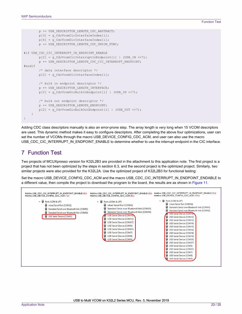
#if USB_CDC_CIC_INTERRUPT_IN_ENDPOINT_ENABLE p[2] = g_CdcVcomCicInterruptInEndpoint[i] | (USB_IN <<7); p += USB_DESCRIPTOR_LENGTH_CDC_CIC_INTERRUPT_ENDPOINT;#endif /* data interface descriptor */ p[2] = g_CdcVcomDicInterfaceIndex[i];
/* bulk in endpoint descriptor */ p += USB_DESCRIPTOR_LENGTH_INTERFACE; p[2] = g_CdcVcomDicBulkInEndpoint[i] | (USB_IN <<7);
/* bulk out endpoint descriptor */ p += USB_DESCRIPTOR_LENGTH_ENDPOINT; p[2] = g_CdcVcomDicBulkOutEndpoint[i] | (USB_OUT <<7); }}
Adding CDC class descriptors manually is also an error-prone step. The array length is very long when 15 VCOM descriptorsare used. This dynamic method makes it easy to configure descriptors. After completing the above four optimizations, user canset the number of VCOMs through the macro USB_DEVICE_CONFIG_CDC_ACM, and user can also use the macroUSB_CDC_CIC_INTERRUPT_IN_ENDPOINT_ENABLE to determine whether to use the interrupt endpoint in the CIC interface.
7 Function TestTwo projects of MCUXpresso version for K32L2B3 are provided in the attachment to this application note. The first project is aproject that has not been optimized by the steps in section 6.3, and the second project is the optimized project. Similarly, twosimilar projects were also provided for the K32L2A. Use the optimized project of K32L2B3 for functional testing:
Set the macro USB_DEVICE_CONFIG_CDC_ACM and the macro USB_CDC_CIC_INTERRUPT_IN_ENDPOINT_ENDABLE toa different value, then compile the project to download the program to the board, the results are as shown in Figure 11.
NXP SemiconductorsFunction Test
USB to Multi VCOM on K32L2 Series MCU, Rev. 0, November 2019Application Note 23 / 25

Figure 11. USB host recognition result
When not using the Interrupt IN endpoint in the CIC interface, a USB device can support up to 15 VCOMs; when using an InterruptIN endpoint, a USB device can support up to 7 VCOMs.
If the window system comes with a CDC driver, users do not need to manually install the driver; if the CDC driveris not installed on the PC, users need to manually drive the driver. For the driver installation, refer to the attachedreadme.pdf document.
NOTE
8 ConclusionBased on the SDK code, this application note implements the function of an FS USB device to multi VCOMs on the K32L2 seriesMCU. It can support up to 15 VCOMs, and each VCOM implements the function of returning received data to the host.
9 References1. AN12458 USB to Virtual COM on LPC54018 and LPC5500.
2. K32L2B3 Reference Manual.
3. USB 2.0 Specification
4. USB in MCU-Signal and Protocol.
5. Access USB Technology and Application based on Microcontrollers.
NXP SemiconductorsConclusion
USB to Multi VCOM on K32L2 Series MCU, Rev. 0, November 2019Application Note 24 / 25

How To Reach Us
Home Page:
nxp.com
Web Support:
nxp.com/support
Information in this document is provided solely to enable system and software implementers touse NXP products. There are no express or implied copyright licenses granted hereunder todesign or fabricate any integrated circuits based on the information in this document. NXPreserves the right to make changes without further notice to any products herein.
NXP makes no warranty, representation, or guarantee regarding the suitability of its products forany particular purpose, nor does NXP assume any liability arising out of the application or useof any product or circuit, and specifically disclaims any and all liability, including without limitationconsequential or incidental damages. “Typical” parameters that may be provided in NXP datasheets and/or specifications can and do vary in different applications, and actual performancemay vary over time. All operating parameters, including “typicals,” must be validated for eachcustomer application by customer's technical experts. NXP does not convey any license underits patent rights nor the rights of others. NXP sells products pursuant to standard terms andconditions of sale, which can be found at the following address: nxp.com/SalesTermsandConditions.
While NXP has implemented advanced security features, all products may be subject tounidentified vulnerabilities. Customers are responsible for the design and operation of theirapplications and products to reduce the effect of these vulnerabilities on customer’s applicationsand products, and NXP accepts no liability for any vulnerability that is discovered. Customersshould implement appropriate design and operating safeguards to minimize the risks associatedwith their applications and products.
NXP, the NXP logo, NXP SECURE CONNECTIONS FOR A SMARTER WORLD, COOLFLUX,EMBRACE, GREENCHIP, HITAG, I2C BUS, ICODE, JCOP, LIFE VIBES, MIFARE, MIFARECLASSIC, MIFARE DESFire, MIFARE PLUS, MIFARE FLEX, MANTIS, MIFARE ULTRALIGHT,MIFARE4MOBILE, MIGLO, NTAG, ROADLINK, SMARTLX, SMARTMX, STARPLUG, TOPFET,TRENCHMOS, UCODE, Freescale, the Freescale logo, AltiVec, C‑5, CodeTEST, CodeWarrior,ColdFire, ColdFire+, C‑Ware, the Energy Efficient Solutions logo, Kinetis, Layerscape, MagniV,mobileGT, PEG, PowerQUICC, Processor Expert, QorIQ, QorIQ Qonverge, Ready Play,SafeAssure, the SafeAssure logo, StarCore, Symphony, VortiQa, Vybrid, Airfast, BeeKit,BeeStack, CoreNet, Flexis, MXC, Platform in a Package, QUICC Engine, SMARTMOS, Tower,TurboLink, UMEMS, EdgeScale, EdgeLock, eIQ, and Immersive3D are trademarks of NXP B.V.All other product or service names are the property of their respective owners. AMBA, Arm,Arm7, Arm7TDMI, Arm9, Arm11, Artisan, big.LITTLE, Cordio, CoreLink, CoreSight, Cortex,DesignStart, DynamIQ, Jazelle, Keil, Mali, Mbed, Mbed Enabled, NEON, POP, RealView,SecurCore, Socrates, Thumb, TrustZone, ULINK, ULINK2, ULINK-ME, ULINK-PLUS, ULINKpro,µVision, Versatile are trademarks or registered trademarks of Arm Limited (or its subsidiaries) inthe US and/or elsewhere. The related technology may be protected by any or all of patents,copyrights, designs and trade secrets. All rights reserved. Oracle and Java are registeredtrademarks of Oracle and/or its affiliates. The Power Architecture and Power.org word marksand the Power and Power.org logos and related marks are trademarks and service markslicensed by Power.org.
© NXP B.V. 2019. All rights reserved.
For more information, please visit: http://www.nxp.comFor sales office addresses, please send an email to: [email protected]
Date of release: November 2019Document identifier: AN12597